US6483471B1 - Combination linearly polarized and quadrifilar antenna - Google Patents
Combination linearly polarized and quadrifilar antennaDownload PDFInfo
- Publication number
- US6483471B1 US6483471B1US09/875,728US87572801AUS6483471B1US 6483471 B1US6483471 B1US 6483471B1US 87572801 AUS87572801 AUS 87572801AUS 6483471 B1US6483471 B1US 6483471B1
- Authority
- US
- United States
- Prior art keywords
- antenna
- coaxial cable
- quarter
- center conductor
- wave
- Prior art date
- Legal status (The legal status is an assumption and is not a legal conclusion. Google has not performed a legal analysis and makes no representation as to the accuracy of the status listed.)
- Expired - Lifetime
Links
- 239000004020conductorSubstances0.000claimsabstractdescription85
- 230000010287polarizationEffects0.000claimsabstractdescription8
- 239000002184metalSubstances0.000claimsdescription56
- 230000008878couplingEffects0.000claimsdescription10
- 238000010168coupling processMethods0.000claimsdescription10
- 238000005859coupling reactionMethods0.000claimsdescription10
- 230000005404monopoleEffects0.000claimsdescription6
- 230000001413cellular effectEffects0.000claimsdescription3
- 238000010586diagramMethods0.000description5
- 230000000694effectsEffects0.000description3
- 230000005855radiationEffects0.000description3
- 230000003993interactionEffects0.000description2
- 230000015556catabolic processEffects0.000description1
- 238000006731degradation reactionMethods0.000description1
- 238000002955isolationMethods0.000description1
- 238000004519manufacturing processMethods0.000description1
Images


Classifications
- H—ELECTRICITY
- H01—ELECTRIC ELEMENTS
- H01Q—ANTENNAS, i.e. RADIO AERIALS
- H01Q21/00—Antenna arrays or systems
- H01Q21/28—Combinations of substantially independent non-interacting antenna units or systems
- H—ELECTRICITY
- H01—ELECTRIC ELEMENTS
- H01Q—ANTENNAS, i.e. RADIO AERIALS
- H01Q11/00—Electrically-long antennas having dimensions more than twice the shortest operating wavelength and consisting of conductive active radiating elements
- H01Q11/02—Non-resonant antennas, e.g. travelling-wave antenna
- H01Q11/08—Helical antennas
- H—ELECTRICITY
- H01—ELECTRIC ELEMENTS
- H01Q—ANTENNAS, i.e. RADIO AERIALS
- H01Q9/00—Electrically-short antennas having dimensions not more than twice the operating wavelength and consisting of conductive active radiating elements
- H01Q9/04—Resonant antennas
- H01Q9/16—Resonant antennas with feed intermediate between the extremities of the antenna, e.g. centre-fed dipole
Definitions
- the inventionrelates generally to a combination satellite and terrestrial antenna, and more particularly to a combination linearly polarized and quadrifilar antenna able to provide excellent performance for both antennas.
- FIG. 1illustrates the monopole/quadrifilar antenna 10 discussed in the McCarrick article.
- the antenna 10includes a monopole 15 whose reflective element is a quarter-wave choke 14 . Elements 14 and 15 form dipole antenna 13 .
- the antenna 10comprises a coaxial line 12 with a section of the outer conductor removed to expose the center conductor 15 .
- the quarter-wave choke 14is placed within a quadrifilar helix antenna shell 16 in an axially concentric fashion.
- the quadrifilar helix antennais typically phased to produce circular polarization. Appropriate placement of the dipole antenna 14 within the quadrifilar antenna is critical for avoiding coupling between the two antennas and avoiding degradation of radiation patterns.
- a combined antenna as described abovehas the disadvantages of having strict design requirements in terms of relative placement between antennas to avoid interference between the antennas and further requires a wider overall structure that may not necessarily be aesthetically pleasing. It is very difficult to optimize due to interactions between the dipole and quadrifilar helix. Furthermore, it is a mechanically-challenging structure and difficult to manufacture. The typical placement for such a combined antenna would be on the sloping back windshield of a vehicle. In this instance, for good satellite reception, care must be taken to ensure that most of the quadrifilar antenna “clears” the line of sight with the transmitting satellite that may be blocked by the roof of the vehicle.
- a combination linearly polarized antenna and quadrifilar helix antennacomprises a quadrifilar antenna having a first coaxial cable and an antenna with linear polarization external to the quadrifilar antenna and having a second coaxial cable.
- a center conductor of the second coaxial cableis isolated from a center conductor of the first coaxial cable and the first coaxial cable runs substantially concentrically through the antenna with linear polarization.
- a combination dipole and quadrifilar helix antennacomprises a quadrifilar antenna having a first coaxial cable and a dipole antenna external to the quadrifilar antenna and having a second coaxial cable.
- a center conductor of the second coaxial cableis isolated from a center conductor of the first coaxial cable and the second coaxial cable runs substantially concentrically through the quadrifilar helix antenna.
- a combination linearly polarized antenna and quadrifilar helix antennacomprises a quadrifilar antenna and a linearly polarized antenna vertically aligned and external to each other.
- the combination antennafurther comprises a first coaxial cable running substantially concentric within at least a portion of the combination linearly polarized antenna and quadrifilar helix antenna serving as a coaxial feed to a quadrifilar feed network for the quadrifilar antenna and a second coaxial cable running substantially concentric within at least a portion of the combination linearly polarized antenna and quadrifilar helix antenna and serving as a quarter-wave extension for the linearly polarized antenna.
- a tubular dipole antennacomprises a coaxial cable having and an inner conductor and an outer conductor both running vertically and substantially concentrically through a quarter-wave metal sleeve.
- the tubular dipole antennafurther comprises a shorted end formed from the connection of the outer conductor of the coaxial cable to an end of the quarter-wave metal sleeve and a quarter-wave hollow metal tube connected to the inner conductor of the coaxial cable extending from the end of the quarter-wave metal sleeve.
- FIG. 1illustrates an existing monopole/quadrifilar antenna.
- FIG. 2illustrates a standard sleeve dipole as may be used in accordance with the present invention.
- FIG. 3illustrates a linearly polarized antenna in the form of a “tube” dipole with a quarter-wave hollow metal tube connected to a coaxial cable's inner conductor as may be used in accordance with the present invention.
- FIG. 3Aillustrates multiple “tube” dipole antennas with several hollow metal tubes substantially concentrically formed in accordance with the present invention.
- FIG. 3Billustrates another multiple “tube” dipole antenna(s) with a hollow metal tube substantially concentrically formed in accordance with the present invention.
- FIG. 3Cillustrates yet another multiple “tube” dipole antenna(s) with a hollow metal tubes substantially concentrically formed in accordance with the present invention.
- FIG. 4is a diagram illustrating the combination of a quadrifilar and dipole antenna in accordance with the present invention.
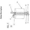
- FIG. 5is a diagram illustrating a balun in accordance with the present invention.
- FIG. 6is a diagram illustrating a first alternative implementation of the combination of a quadrifilar and dipole antenna in accordance with the present invention.
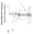
- FIG. 7is a diagram illustrating a second alternative implementation of the combination of a quadrifilar and dipole antenna in accordance with the present invention.
- FIG. 8is a diagram illustrating a third alternative implementation of the combination of a quadrifilar and dipole antenna in accordance with the present invention.
- a combination linearly polarized/quadrifilar helix antenna 40is illustrated in FIG. 4 .
- itconsists of a new tubular dipole antenna 44 that is placed coaxially underneath the quadrifilar helix, but it should be noted that other types of dipole antennas, patches, or loop antennas (being linearly polarized) could easily replace the tubular dipole antenna and still be within contemplation of the scope of the present invention.
- a (first) coaxial cable 46is passed through the new tubular dipole with minimum effect on its performance. That coaxial cable 46 is connected to a feed network 48 of the quadrifilar helix antenna 49 .
- feed network 48 and quadrifilar shell 47form the quadrifilar hexlix antenna 49 .
- a (second) coaxial cable 42preferably couples to a quarter wave hollow metal tube coupled to an inner conductor of coaxial cable 42 forming the tubular dipole antenna 44 .
- the outer conductor of cable 42 (shield)is physically connected to the outer conductor (shield) of cable 46 and both are also connected to the shorted top section of tube 45 .
- This configurationresults in excellent performance for both antennas.
- Coaxial cable 46has a minimum effect on dipole 44 due to the dipoles tubular structure. Also, this configuration results in minimum interaction between quadrifilar antenna 49 and dipole 44 .
- FIG. 2provides a more detailed illustration of a commercial sleeve dipole 20 .
- the dipole 20includes a coaxial cable 22 having an inner conductor 24 .
- the coaxial cable 22preferably runs vertically and concentrically through a quarter-wave metal sleeve 26 shorted at one end (top) and connected to the outer conductor (shield) of cable 22 at the shorted end.
- This structureis known as a balun.
- the balunis shown with a short 28 between an outer conductor of the coaxial cable 22 and the metal sleeve 26 .
- the dipole 20finally comprises a quarter-wave extension 25 of the inner conductor 24 .
- FIG. 3illustrates a sleeve dipole where conductor 25 of FIG. 2 is replaced by tube 29 .
- Tubular dipole 30preferably comprises coaxial cable 22 , inner conductor 24 , and the balun with the quarter-wave metal sleeve 26 as previously described with FIG. 2 .
- the inner conductor 24 extending from the top of the balunis coupled (connected) to a quarter-wave hollow metal tube 29 .
- a multiple tubular dipole antenna 31is shown. It should be understood that although antenna 31 (and 33 and 35 ) are referred to in the singular, they are truly multiple antennas.
- the antenna 31comprises a coaxial cable 22 having and an inner conductor 24 and an outer conductor both running vertically and substantially concentrically through a quarter-wave metal sleeve 26 .
- the antenna 31further comprises a shorted end 28 formed from the connection of the outer conductor of the coaxial cable 22 to an end of the quarter-wave metal sleeve 26 .
- a quarter-wave hollow metal tube 29is connected to the inner conductor 24 of the coaxial cable extending from the end of the quarter-wave metal sleeve 26 .
- a tubular dipole antenna within contemplation of the present inventioncould have multiple antennas. As shown in FIG. 3A, an additional dipole antenna is configured substantially concentrically above the quarter-wave hollow metal tube 29 using another quarter-wave metal sleeve 36 and hollow metal tube 39 .
- the antenna 31further comprises a shorted end 38 formed from the connection of the outer conductor of the coaxial cable 32 to an end of the quarter-wave metal sleeve 36 .
- the hollow metal tube 39is connected to the inner conductor 34 of the coaxial cable 32 extending from the end of the quarter-wave metal sleeve 36 . It should be understood that several hollow tubes and metal sleeves could be configured in a similar fashion to provide multiple substantially concentric antennas that can be vertically stacked or even placed (or partially placed) within each other. In this instance, only two antennas are shown for simplicity.
- antenna 33illustrates a similar embodiment to the antenna 31 of FIG. 3A, except that the hollow metal tube 39 is replaced with the extension 37 serving as a monopole.
- antenna 35illustrates yet another similar embodiment to the antenna 33 of FIG. 3B, except that the metal sleeve 36 ′ is shown with a slightly smaller diameter than the quarter-wave metal sleeve 36 of FIG. 3 B. Furthermore, the metal sleeve 36 ′ is placed partially within the hollow metal tube 29 as opposed to being external thereto.
- the design of a multiple tubular antennamight vary drastically, yet still be in contemplation of the present invention as claimed.
- the metal sleeve 36 ′could reside partially within tube 29 as shown or completely within tube 29 or completely external thereto.
- the extension 37 ′may vary in length based on the configuration and frequency requirements.
- the antenna in accordance with this aspect of the present inventioncould be used for multiple applications. For example, one antenna could be configured for cellular use at one frequency and another antenna configured for receiving GPS signals at another frequency and yet a third antenna could be configured to receive signals from a terrestrial repeater at yet another frequency.
- a coaxial cable 46is passed through the new tubular dipole (FIG. 3) with minimum effect on its performance.
- This coaxial cable 46is connected to the feed network 48 of the quadrifilar helix antenna 49 .
- FIG. 5More design details are shown in FIG. 5 illustrating a balun 50 .
- the balun 50preferably comprises the coaxial cable 53 for the quadrifilar helix antenna having an inner conductor 54 that will couple to the feed network of the quadrifilar.
- the balunalso preferably comprises another coaxial cable 51 having an inner conductor 52 . Both coaxial cables 51 and 53 run vertically and concentrically through the quarter-wave metal sleeve 55 shorted at one end forming the balun.
- the balun 50finally includes an extension 57 of the inner conductor 52 that will form the quarter-wave extension of the dipole.
- the quarter-wave extensioncan be formed in multiple forms as illustrated by FIGS. 4-7. In FIG. 4, a quarter-wave hollow metal tube is connected to form the quarter-wave extension. It should be noted that the quarter-wave extension is not necessarily one quarter-wavelength long. Other physical lengths can be used in order to make the antenna efficient, resulting in a desired radiation pattern.
- balun 60similar to balun 50 of FIG. 5, shows a coaxial cable 61 having an inner conductor 62 connected to a quarter-wave extension 67 .
- Extension 67is running vertically parallel with coaxial cable 53 at a predetermined distance or a predetermined radius away.
- the dipole radiation patternwill be skewed due to the presence of coaxial cable 53 .
- the average gain over the horizonis close to that of a dipole tested in free field.
- a balun 70similar to balun 50 of FIG.
- FIG. 5shows a coaxial cable 71 having an inner conductor 72 that is isolated from the center conductor 54 of the coaxial cable 53 , and is preferably connected to a helix extension 77 .
- the helix extension 77forms a radiator portion in the form of a helix a predetermined distance about the center conductor 54 of the coaxial cable 53 as shown.
- a combination dipole/ quadrifilar helix antenna 80preferably comprises a quadrifilar antenna 82 having a first coaxial cable (not shown) and a dipole antenna 86 external to the quadrifilar antenna 82 and having a second coaxial cable 84 .
- a center conductor of the second coaxial cable 84is isolated from a center conductor of the first coaxial cable and the second coaxial cable runs substantially concentrically through the quadrifilar helix antenna 82 .
- the dipole antenna 86is preferably arranged vertically above the quadrifilar helix antenna at some distance away (not shown).
- a combination antenna 40comprises a quadrifilar antenna 49 and a linearly polarized antenna 44 vertically aligned and external to each other having a first coaxial cable 46 running substantially concentric within at least a portion of the combination linearly polarized antenna 44 and quadrifilar helix antenna 49 serving as a coaxial feed to a quadrifilar feed network 48 for the quadrifilar antenna and further having a second coaxial cable 42 running substantially concentric within at least a portion of the combination linearly polarized antenna and quadrifilar helix antenna 40 and serving as a quarter-wave extension for the linearly polarized antenna 44 .
- the linearly polarized antennacan be a dipole antenna, a loop antenna, or a patch antenna or any other suitable linearly polarized antenna.
- the dipole antennacan be arranged vertically below or vertically above the quadrifilar helix antenna. When the dipole antenna is placed below, it is particularly advantageous for the quadrifilar helix in terms of providing greater exposure to line of sight reception of satellite signals.
- the center conductor of the second coaxial cableis isolated from a center conductor 54 of the first coaxial cable 53 in several different ways. As shown in FIGS.
- the center conductor of coaxial cable for the dipole antenna(the second coaxial cable) is isolated from the center conductor of the coaxial cable for the quadrifilar (the first coaxial cable) by coupling a quarter-wave hollow metal tube ( 29 ) to the center conductor of the second coaxial cable.
- the center conductor 62 of the second coaxial cable 61is isolated from a center conductor 54 of the first coaxial cable 53 by coupling a quarter-wave extension 67 of the center conductor of the second coaxial cable a predetermined radius away running vertically parallel from the center conductor of the first coaxial cable.
- a helix extension of the center conductor of the second coaxial cableforms a quarter-wave extension by forming a helix about the center conductor of the first coaxial cable as shown in FIG. 7 .
- the coaxial cables in the various embodimentsrun vertically and concentric to the cavities of the quadrifilar and/or linearly polarized antennas, it should be noted the coaxial cables may also run substantially concentric thereto and still provide excellent performance as contemplated within the scope of the present invention.
- the embodiments described hereinshould not limit the scope of the invention.
- the quadrifilar antenna in accordance with the present inventioncan be tuned to receive signals not only for Satellite Digital Audio Radio System-(SDARS) signals, but also global positioning satellite signals, or other suitable satellite signals.
- the linearly polarized antenna in accordance with the present inventioncan be tuned to receive not only signals from SDARS terrestrial repeaters, but also cellular signals, paging signals, FM radio signals, AM radio signals, or other suitable signals for reception by the linearly polarized antenna.
Landscapes
- Details Of Aerials (AREA)
- Variable-Direction Aerials And Aerial Arrays (AREA)
Abstract
Description
Claims (24)
Priority Applications (1)
| Application Number | Priority Date | Filing Date | Title |
|---|---|---|---|
| US09/875,728US6483471B1 (en) | 2001-06-06 | 2001-06-06 | Combination linearly polarized and quadrifilar antenna |
Applications Claiming Priority (1)
| Application Number | Priority Date | Filing Date | Title |
|---|---|---|---|
| US09/875,728US6483471B1 (en) | 2001-06-06 | 2001-06-06 | Combination linearly polarized and quadrifilar antenna |
Publications (2)
| Publication Number | Publication Date |
|---|---|
| US6483471B1true US6483471B1 (en) | 2002-11-19 |
| US20020186171A1 US20020186171A1 (en) | 2002-12-12 |
Family
ID=25366261
Family Applications (1)
| Application Number | Title | Priority Date | Filing Date |
|---|---|---|---|
| US09/875,728Expired - LifetimeUS6483471B1 (en) | 2001-06-06 | 2001-06-06 | Combination linearly polarized and quadrifilar antenna |
Country Status (1)
| Country | Link |
|---|---|
| US (1) | US6483471B1 (en) |
Cited By (26)
| Publication number | Priority date | Publication date | Assignee | Title |
|---|---|---|---|---|
| US6621458B1 (en)* | 2002-04-02 | 2003-09-16 | Xm Satellite Radio, Inc. | Combination linearly polarized and quadrifilar antenna sharing a common ground plane |
| US6720935B2 (en)* | 2002-07-12 | 2004-04-13 | The Mitre Corporation | Single and dual-band patch/helix antenna arrays |
| US20040108962A1 (en)* | 2002-12-06 | 2004-06-10 | Tsai Churng-Jou | Dual-frequency broadband antennas |
| US20040113858A1 (en)* | 2002-12-14 | 2004-06-17 | Churng-Jou Tsai | Broadband dual-frequency tablet antennas |
| US20040222935A1 (en)* | 2003-04-23 | 2004-11-11 | Wistron Neweb Corp. | Complex antenna apparatus |
| US6864853B2 (en)* | 1999-10-15 | 2005-03-08 | Andrew Corporation | Combination directional/omnidirectional antenna |
| US6985121B1 (en)* | 2003-10-21 | 2006-01-10 | R.A. Miller Industries, Inc. | High powered multiband antenna |
| US20060022891A1 (en)* | 2004-07-28 | 2006-02-02 | O'neill Gregory A Jr | Quadrifilar helical antenna |
| US20060022892A1 (en)* | 2004-07-28 | 2006-02-02 | O'neill Gregory A Jr | Handset quadrifilar helical antenna mechanical structures |
| US7064728B1 (en)* | 2004-12-24 | 2006-06-20 | Advanced Connectek Inc. | Ultra-wideband dipole antenna |
| US7239286B1 (en)* | 2003-10-21 | 2007-07-03 | R.A. Miller Industries, Inc. | Antenna with dipole connector |
| US20070247371A1 (en)* | 2006-04-25 | 2007-10-25 | Waldemar Kunysz | Dual sphere uwb antenna |
| US7289080B1 (en)* | 2006-06-28 | 2007-10-30 | Bae Systems Information And Electronic Systems Integration Inc. | Ultra broadband linear antenna |
| US20080246679A1 (en)* | 2007-04-05 | 2008-10-09 | Martek Gary A | Small, narrow profile multiband antenna |
| US20100220026A1 (en)* | 2005-06-02 | 2010-09-02 | Torleif Martin | Broadband Lossless Dipole Antenna |
| US20110163928A1 (en)* | 2008-10-30 | 2011-07-07 | Rohde & Schwarz Gmbh & Co. Kg | Broadband antenna |
| US8010042B2 (en) | 1999-07-20 | 2011-08-30 | Andrew Llc | Repeaters for wireless communication systems |
| US20120133568A1 (en)* | 2010-11-29 | 2012-05-31 | 2201028 Ontario Inc. | Quadrifilar helix antenna system with ground plane |
| US20130009832A1 (en)* | 2011-07-07 | 2013-01-10 | Apostolos John T | Dual uhf dipole quadrafiler helix antenna |
| WO2014134149A1 (en) | 2013-03-01 | 2014-09-04 | Harris Corporation | Dipole antenna assembly having an electrical conductor extending through tubular segments and related methods |
| US9614293B2 (en) | 2012-10-17 | 2017-04-04 | The Mitre Corporation | Multi-band helical antenna system |
| US9666948B1 (en) | 2016-02-02 | 2017-05-30 | Northrop Grumman Systems Corporation | Compact cross-link antenna for next generation global positioning satellite constellation |
| CN107546486A (en)* | 2016-06-23 | 2018-01-05 | 康普技术有限责任公司 | Antenna feed elements with constant reverse phase |
| CN108370092A (en)* | 2016-11-14 | 2018-08-03 | 天传科技有限公司 | System, apparatus and method for optimizing antenna performance |
| US20190028902A1 (en)* | 2017-07-24 | 2019-01-24 | Motorola Solutions, Inc. | Passive radio-frequency redirector device |
| US10511098B2 (en)* | 2017-04-11 | 2019-12-17 | Yi Zhang | Antennas |
Families Citing this family (7)
| Publication number | Priority date | Publication date | Assignee | Title |
|---|---|---|---|---|
| US7692597B2 (en)* | 2007-02-21 | 2010-04-06 | Antennasys, Inc. | Multi-feed dipole antenna and method |
| US7982683B2 (en)* | 2007-09-26 | 2011-07-19 | Ibiquity Digital Corporation | Antenna design for FM radio receivers |
| US8451185B2 (en)* | 2008-02-21 | 2013-05-28 | Antennasys, Inc. | Multi-feed dipole antenna and method |
| CN201518352U (en)* | 2009-08-26 | 2010-06-30 | 国基电子(上海)有限公司 | Dual-frequency antenna combination |
| US20210143547A1 (en)* | 2019-11-13 | 2021-05-13 | Skywave Antennas, Inc. | Ultra-wideband antenna |
| EP4088346A1 (en) | 2020-01-08 | 2022-11-16 | Sony Group Corporation | Compound antenna device for omnidirectional coverage |
| DE102020210511A1 (en)* | 2020-08-19 | 2022-02-24 | Hagenuk Marinekommunikation Gmbh | Antenna with a first and a second feed point |
Citations (5)
| Publication number | Priority date | Publication date | Assignee | Title |
|---|---|---|---|---|
| US3100893A (en)* | 1960-11-30 | 1963-08-13 | Helmut Brueckmann | Broad band vertical antenna with adjustable impedance matching network |
| US3750181A (en)* | 1971-09-07 | 1973-07-31 | Radionics Inc | Ground independent antenna |
| US4963879A (en)* | 1989-07-31 | 1990-10-16 | Alliance Telecommunications Corp. | Double skirt omnidirectional dipole antenna |
| US6005521A (en)* | 1996-04-25 | 1999-12-21 | Kyocera Corporation | Composite antenna |
| US6150981A (en)* | 1998-04-02 | 2000-11-21 | Kyocera Corporation | Plane antenna, and portable radio using thereof |
- 2001
- 2001-06-06USUS09/875,728patent/US6483471B1/ennot_activeExpired - Lifetime
Patent Citations (5)
| Publication number | Priority date | Publication date | Assignee | Title |
|---|---|---|---|---|
| US3100893A (en)* | 1960-11-30 | 1963-08-13 | Helmut Brueckmann | Broad band vertical antenna with adjustable impedance matching network |
| US3750181A (en)* | 1971-09-07 | 1973-07-31 | Radionics Inc | Ground independent antenna |
| US4963879A (en)* | 1989-07-31 | 1990-10-16 | Alliance Telecommunications Corp. | Double skirt omnidirectional dipole antenna |
| US6005521A (en)* | 1996-04-25 | 1999-12-21 | Kyocera Corporation | Composite antenna |
| US6150981A (en)* | 1998-04-02 | 2000-11-21 | Kyocera Corporation | Plane antenna, and portable radio using thereof |
Non-Patent Citations (1)
| Title |
|---|
| Microwave Journal, "A Combination Monopole/Quadrifilar Helix Antenna for S-Band Terrestrial/Satellite Applications", May 2001; McCarrick, Charles D. |
Cited By (47)
| Publication number | Priority date | Publication date | Assignee | Title |
|---|---|---|---|---|
| US8358970B2 (en) | 1999-07-20 | 2013-01-22 | Andrew Corporation | Repeaters for wireless communication systems |
| US8630581B2 (en) | 1999-07-20 | 2014-01-14 | Andrew Llc | Repeaters for wireless communication systems |
| US8010042B2 (en) | 1999-07-20 | 2011-08-30 | Andrew Llc | Repeaters for wireless communication systems |
| US8971796B2 (en) | 1999-07-20 | 2015-03-03 | Andrew Llc | Repeaters for wireless communication systems |
| US6864853B2 (en)* | 1999-10-15 | 2005-03-08 | Andrew Corporation | Combination directional/omnidirectional antenna |
| US6621458B1 (en)* | 2002-04-02 | 2003-09-16 | Xm Satellite Radio, Inc. | Combination linearly polarized and quadrifilar antenna sharing a common ground plane |
| US6720935B2 (en)* | 2002-07-12 | 2004-04-13 | The Mitre Corporation | Single and dual-band patch/helix antenna arrays |
| US6809697B2 (en)* | 2002-12-06 | 2004-10-26 | Antenniques Corp. | Dual-frequency broadband antennas |
| US20040108962A1 (en)* | 2002-12-06 | 2004-06-10 | Tsai Churng-Jou | Dual-frequency broadband antennas |
| US6809698B2 (en)* | 2002-12-14 | 2004-10-26 | Antennigues Corp. | Broadband dual-frequency tablet antennas |
| US20040113858A1 (en)* | 2002-12-14 | 2004-06-17 | Churng-Jou Tsai | Broadband dual-frequency tablet antennas |
| US20040222935A1 (en)* | 2003-04-23 | 2004-11-11 | Wistron Neweb Corp. | Complex antenna apparatus |
| US7091917B2 (en) | 2003-04-23 | 2006-08-15 | Wistron Neweb Corp. | Complex antenna apparatus |
| US6985121B1 (en)* | 2003-10-21 | 2006-01-10 | R.A. Miller Industries, Inc. | High powered multiband antenna |
| US7239286B1 (en)* | 2003-10-21 | 2007-07-03 | R.A. Miller Industries, Inc. | Antenna with dipole connector |
| US20060022891A1 (en)* | 2004-07-28 | 2006-02-02 | O'neill Gregory A Jr | Quadrifilar helical antenna |
| US20060022892A1 (en)* | 2004-07-28 | 2006-02-02 | O'neill Gregory A Jr | Handset quadrifilar helical antenna mechanical structures |
| US7173576B2 (en) | 2004-07-28 | 2007-02-06 | Skycross, Inc. | Handset quadrifilar helical antenna mechanical structures |
| US7245268B2 (en) | 2004-07-28 | 2007-07-17 | Skycross, Inc. | Quadrifilar helical antenna |
| US7064728B1 (en)* | 2004-12-24 | 2006-06-20 | Advanced Connectek Inc. | Ultra-wideband dipole antenna |
| US20060139228A1 (en)* | 2004-12-24 | 2006-06-29 | Advanced Connectek Inc. | Ultra-wideband dipole antenna |
| US20100220026A1 (en)* | 2005-06-02 | 2010-09-02 | Torleif Martin | Broadband Lossless Dipole Antenna |
| US8054236B2 (en)* | 2005-06-02 | 2011-11-08 | Totalfösvarets Forskningsinstitut | Broadband lossless dipole antenna |
| US20070247371A1 (en)* | 2006-04-25 | 2007-10-25 | Waldemar Kunysz | Dual sphere uwb antenna |
| US7289080B1 (en)* | 2006-06-28 | 2007-10-30 | Bae Systems Information And Electronic Systems Integration Inc. | Ultra broadband linear antenna |
| US20080246679A1 (en)* | 2007-04-05 | 2008-10-09 | Martek Gary A | Small, narrow profile multiband antenna |
| US7589694B2 (en)* | 2007-04-05 | 2009-09-15 | Shakespeare Company, Llc | Small, narrow profile multiband antenna |
| US20110163928A1 (en)* | 2008-10-30 | 2011-07-07 | Rohde & Schwarz Gmbh & Co. Kg | Broadband antenna |
| US8570232B2 (en)* | 2008-10-30 | 2013-10-29 | Rohde & Schwarz Gmbh & Co. Kg | Broadband antenna |
| US8836600B2 (en)* | 2010-11-29 | 2014-09-16 | Skywave Mobile Communications Inc. | Quadrifilar helix antenna system with ground plane |
| US20120133568A1 (en)* | 2010-11-29 | 2012-05-31 | 2201028 Ontario Inc. | Quadrifilar helix antenna system with ground plane |
| US20130009832A1 (en)* | 2011-07-07 | 2013-01-10 | Apostolos John T | Dual uhf dipole quadrafiler helix antenna |
| US8786503B2 (en)* | 2011-07-07 | 2014-07-22 | Bae Systems Information And Electronic Systems Integration Inc. | Dual UHF dipole quadrafiler helix antenna |
| US9614293B2 (en) | 2012-10-17 | 2017-04-04 | The Mitre Corporation | Multi-band helical antenna system |
| US10044107B2 (en) | 2012-10-17 | 2018-08-07 | The Mitre Corporation | Multi-band helical antenna system |
| US9083076B2 (en) | 2013-03-01 | 2015-07-14 | Harris Corporation | Dipole antenna assembly having an electrical conductor extending through tubular segments and related methods |
| WO2014134149A1 (en) | 2013-03-01 | 2014-09-04 | Harris Corporation | Dipole antenna assembly having an electrical conductor extending through tubular segments and related methods |
| US9666948B1 (en) | 2016-02-02 | 2017-05-30 | Northrop Grumman Systems Corporation | Compact cross-link antenna for next generation global positioning satellite constellation |
| US10950947B2 (en) | 2016-06-23 | 2021-03-16 | Commscope Technologies Llc | Antenna feed elements with constant inverted phase |
| CN107546486A (en)* | 2016-06-23 | 2018-01-05 | 康普技术有限责任公司 | Antenna feed elements with constant reverse phase |
| CN107546486B (en)* | 2016-06-23 | 2021-06-29 | 康普技术有限责任公司 | Antenna feed element with constant inverted phase |
| CN108370092A (en)* | 2016-11-14 | 2018-08-03 | 天传科技有限公司 | System, apparatus and method for optimizing antenna performance |
| CN108370092B (en)* | 2016-11-14 | 2020-12-25 | 天传科技有限公司 | System, apparatus and method for optimizing antenna performance |
| US10141635B2 (en)* | 2016-11-14 | 2018-11-27 | Antwave Technology Limited | Systems, apparatus, and methods to optimize antenna performance |
| US10511098B2 (en)* | 2017-04-11 | 2019-12-17 | Yi Zhang | Antennas |
| US10939305B2 (en)* | 2017-07-24 | 2021-03-02 | Motorola Solutions, Inc. | Passive radio-frequency redirector device |
| US20190028902A1 (en)* | 2017-07-24 | 2019-01-24 | Motorola Solutions, Inc. | Passive radio-frequency redirector device |
Also Published As
| Publication number | Publication date |
|---|---|
| US20020186171A1 (en) | 2002-12-12 |
Similar Documents
| Publication | Publication Date | Title |
|---|---|---|
| US6483471B1 (en) | Combination linearly polarized and quadrifilar antenna | |
| US9246224B2 (en) | Broadband antenna system allowing multiple stacked collinear devices and having an integrated, co-planar balun | |
| US6320549B1 (en) | Compact dual mode integrated antenna system for terrestrial cellular and satellite telecommunications | |
| US8228257B2 (en) | Broadband antenna system allowing multiple stacked collinear devices | |
| US3940772A (en) | Circularly polarized, broadside firing tetrahelical antenna | |
| US6567045B2 (en) | Wide-angle circular polarization antenna | |
| US7352337B2 (en) | Portable SDARS-receiving device with integrated audio wire and antenna | |
| WO2011142231A1 (en) | Cobra antenna | |
| US6621458B1 (en) | Combination linearly polarized and quadrifilar antenna sharing a common ground plane | |
| US9306273B2 (en) | Multifilar antenna | |
| CN109742519B (en) | Broadband spiral combination multi-network antenna | |
| US7515113B2 (en) | Antenna with parasitic rings | |
| US6535179B1 (en) | Drooping helix antenna | |
| JP4938561B2 (en) | Antenna device and horizontal polarization non-directional antenna for horizontal polarization | |
| JP5337621B2 (en) | Satellite / terrestrial digital broadcasting antenna | |
| JPH10256822A (en) | Dual radiator primary radiator | |
| JPH10163737A (en) | Primary radiator for satellite receiving antenna and converter for satellite receiving | |
| EP1833116B1 (en) | Quadrifilar helical antenna | |
| JP3619800B2 (en) | Antenna unit, antenna device and broadcasting tower | |
| US20030169210A1 (en) | Novel feed structure for quadrifilar helix antenna | |
| JP4237683B2 (en) | Rin Group Antenna Equipment for Digital Terrestrial Broadcasting | |
| GB2034124A (en) | Improved antenna | |
| JPH0467803B2 (en) | ||
| CN112670705A (en) | Satellite-borne circularly polarized antenna | |
| Licul et al. | 1. Markets Reviewing SDARS Antenna Requirements Sept. 1, 2003 Several conflicting requirements, such as achieving two separate high-gain antenna patterns within a single compact module, increase the challenge of designing SDARS antennas. |
Legal Events
| Date | Code | Title | Description |
|---|---|---|---|
| AS | Assignment | Owner name:XM SATELLITE RADIO, INC., DISTRICT OF COLUMBIA Free format text:ASSIGNMENT OF ASSIGNORS INTEREST;ASSIGNOR:PETROS, ARGY;REEL/FRAME:011890/0595 Effective date:20010605 | |
| STCF | Information on status: patent grant | Free format text:PATENTED CASE | |
| AS | Assignment | Owner name:BANK OF NEW YORK, THE, NEW YORK Free format text:SECURITY AGREEMENT;ASSIGNOR:XM SATELLITE RADIO INC.;REEL/FRAME:013684/0221 Effective date:20030128 | |
| FPAY | Fee payment | Year of fee payment:4 | |
| AS | Assignment | Owner name:LIBERTY MEDIA CORPORATION, COLORADO Free format text:SECURITY AGREEMENT;ASSIGNOR:XM SATELLITE RADIO INC.;REEL/FRAME:022354/0205 Effective date:20090306 | |
| AS | Assignment | Owner name:JPMORGAN CHASE BANK, N.A., AS COLLATERAL AGENT, NE Free format text:SECURITY AGREEMENT AMENDMENT;ASSIGNOR:XM SATELLITE RADIO INC.;REEL/FRAME:022449/0587 Effective date:20090306 | |
| AS | Assignment | Owner name:XM SATELLITE RADIO INC., NEW YORK Free format text:RELEASE BY SECURED PARTY;ASSIGNOR:LIBERTY MEDIA CORPORATION;REEL/FRAME:022917/0358 Effective date:20090706 | |
| AS | Assignment | Owner name:U.S. BANK NATIONAL ASSOCIATION, NEW YORK Free format text:ASSIGNMENT AND ASSUMPTION OF SECURITY AGREEMENT RECORDED AT REEL/FRAME NO. 22449/0587;ASSIGNOR:JPMORGAN CHASE BANK, N.A.;REEL/FRAME:023003/0092 Effective date:20090630 | |
| FPAY | Fee payment | Year of fee payment:8 | |
| AS | Assignment | Owner name:XM SATELLITE RADIO INC., NEW YORK Free format text:TERMINATION AND RELEASE OF SECURITY INTEREST IN PATENT RIGHTS;ASSIGNOR:U.S. BANK NATIONAL ASSOCIATION, AS AGENT;REEL/FRAME:025217/0488 Effective date:20101028 | |
| AS | Assignment | Owner name:XM SATELLITE RADIO INC., NEW YORK Free format text:TERMINATION AND RELEASE OF SECURITY INTEREST IN PATENT RIGHTS;ASSIGNOR:THE BANK OF NEW YORK MELLON (F/K/A THE BANK OF NEW YORK), AS COLLATERAL AGENT;REEL/FRAME:025406/0888 Effective date:20101129 | |
| AS | Assignment | Owner name:SIRIUS XM RADIO INC., NEW YORK Free format text:MERGER;ASSIGNOR:XM SATELLITE RADIO INC.;REEL/FRAME:025627/0951 Effective date:20110112 | |
| AS | Assignment | Owner name:U.S. BANK NATIONAL ASSOCIATION, AS COLLATERAL AGEN Free format text:SECURITY AGREEMENT;ASSIGNOR:SIRIUS XM RADIO INC.;REEL/FRAME:025643/0502 Effective date:20110112 | |
| AS | Assignment | Owner name:SIRIUS XM RADIO INC., DELAWARE Free format text:TERMINATION AND RELEASE OF SECURITY INTEREST IN PATENT RIGHTS;ASSIGNOR:U.S. BANK NATIONAL ASSOCIATION;REEL/FRAME:028938/0704 Effective date:20120904 | |
| AS | Assignment | Owner name:JPMORGAN CHASE BANK, N.A., AS ADMINISTRATIVE AGENT Free format text:SECURITY AGREEMENT;ASSIGNOR:SIRIUS XM RADIO INC.;REEL/FRAME:029408/0767 Effective date:20121205 | |
| AS | Assignment | Owner name:U.S. BANK NATIONAL ASSOCIATION, NEW YORK Free format text:PATENT SECURITY AGREEMENT;ASSIGNORS:SIRIUS XM RADIO INC.;SIRIUS XM CONNECTED VEHICLE SERVICES INC.;REEL/FRAME:032660/0603 Effective date:20140410 | |
| FPAY | Fee payment | Year of fee payment:12 | |
| AS | Assignment | Owner name:SIRIUS XM CONNECTED VEHICLE SERVICES INC., NEW YORK Free format text:RELEASE BY SECURED PARTY;ASSIGNOR:U.S. BANK NATIONAL ASSOCIATION;REEL/FRAME:043747/0091 Effective date:20170901 Owner name:SIRIUS XM RADIO INC., NEW YORK Free format text:RELEASE BY SECURED PARTY;ASSIGNOR:U.S. BANK NATIONAL ASSOCIATION;REEL/FRAME:043747/0091 Effective date:20170901 Owner name:SIRIUS XM CONNECTED VEHICLE SERVICES INC., NEW YOR Free format text:RELEASE BY SECURED PARTY;ASSIGNOR:U.S. BANK NATIONAL ASSOCIATION;REEL/FRAME:043747/0091 Effective date:20170901 |