US6483291B1 - Apparatus for measuring electrical power consumption - Google Patents
Apparatus for measuring electrical power consumptionDownload PDFInfo
- Publication number
- US6483291B1 US6483291B1US09/579,687US57968700AUS6483291B1US 6483291 B1US6483291 B1US 6483291B1US 57968700 AUS57968700 AUS 57968700AUS 6483291 B1US6483291 B1US 6483291B1
- Authority
- US
- United States
- Prior art keywords
- voltage
- power
- output signal
- meter
- electrical communication
- Prior art date
- Legal status (The legal status is an assumption and is not a legal conclusion. Google has not performed a legal analysis and makes no representation as to the accuracy of the status listed.)
- Expired - Lifetime
Links
Images

Classifications
- G—PHYSICS
- G01—MEASURING; TESTING
- G01R—MEASURING ELECTRIC VARIABLES; MEASURING MAGNETIC VARIABLES
- G01R22/00—Arrangements for measuring time integral of electric power or current, e.g. electricity meters
- G—PHYSICS
- G01—MEASURING; TESTING
- G01R—MEASURING ELECTRIC VARIABLES; MEASURING MAGNETIC VARIABLES
- G01R21/00—Arrangements for measuring electric power or power factor
- G01R21/06—Arrangements for measuring electric power or power factor by measuring current and voltage
Definitions
- This inventionrelates to an apparatus for measuring the power consumption of an electricity powered device or machine. More specifically, this invention relates to an apparatus which measures the power consumption by calculating the wattage consumed by the electrical device from the measured voltage and current.
- the power consumed by any processis an important parameter useful for optimizing a process.
- the power consumedis indicative of the efficiency of a grinding wheel to remove material in a given operation.
- the grinding wheel consuming less poweris more efficient. Accordingly, it is desirable to measure the power consumed by a given machine.
- Efficiencymay also be calculated based upon the current draw of the load; however, the current draw is typically nonlinear for an inductive motor load wherein the power is a multiple of the voltage, the current, and a “power factor” which is the cosine of the lag angle between the voltage and the current.
- the power factorvaries depending upon the load. For example, an AC motor at idle may have a typical power factor of approximately 0.1 while the power factor of same motor at full load may be approximately 0.8.
- Measurement of the power consumed by an electrical load containing resistance, capacitance, and inductancerequires the measurement of the actual values of the voltage, the current, and the phase angle representing the lag angle between the voltage and the current.
- the power consumptionis calculated by the Hall device which senses the magnetic field created in a current carrying line by the Hall Effect and multiples it by the line voltage, e.g., U.S. Pat. No. 5,438,258, issued to Maruyama and U.S. Pat. No. 4,764,720 issued to Nystrom.
- the prior art sensors based on the Hall deviceare essentially limited to lower frequency applications.
- the power calculated using a typical Hall deviceis limited by the frequency response of such a device and typically loses significant accuracy at frequencies above 1000 Hz.
- the prior art devicestypically require a complex setup procedure requiring the operator to select both the maximum input current and the maximum input voltage.
- the present inventionreduces the need for additional settings requiring the operator to simply select the desired output range of the power meter.
- the prior art devicesare limited in the customization and information available to the operator.
- the devicesare typically intended for self-contained use. For example, when using a portable power meter which is not associated with a single machine, it is desirable to be able to adjust the scale of the output to read the power consumption with some precision.
- prior art devicestypically provide instantaneous power consumption readings using an analog display which suffers from a slow response time and hides small effects from the operator.
- the prior art meters, particularly those with analog displaysdo not provide the operator with important information such as peak power.
- Prior art devices incorporating digital displayshave not been taught having differing measurement units available to the operator.
- the analog displaysmay have multiple scales, the analog devices typically only provide an approximation of the total power consumption subject to the operator's interpretation of the needle position.
- the present inventionprovides an unscaled output along with an operator selectable scaled output allowing more precise measurement of power consumption significantly less than the full scale maximum of the power meter in addition to a default range, full scale output. Additionally, the present invention utilizes a bar LED display for rapid response when displaying the instantaneous power usage and a digital display with user selectable measurement units to provide accurate, non-discretionary power consumption readings coupled with a peak power hold feature.
- the power meter of the present inventionwhile self contained, provides for intelligent communication with external devices.
- a power meterwhich does not require setting of the maximum input current and the maximum input voltage prior to making a measurement. Additionally, there is a need for a power meter which is capable of measuring the power consumption of a load requiring a high frequency power supply without degradation of the measurement accuracy. There is also a need for a power meter providing a fast responding display of instantaneous power consumption, a display of peak power consumption, and providing operator selectable measurement units. Further, there is a need for a power meter providing both scaled and unscaled outputs for external monitoring of the system and providing both high and low trip points. Finally, there is a need for a power meter capable of communicating with and responding to external devices.
- Yet another object of the present inventionis to provide a power meter which provides a fast responding display of the instantaneous power consumption of the load.
- a further object of the present inventionis to provide a power meter which communicates with external devices for remote control of the power meter and remote display of the power meter settings and outputs.
- a still further object of the present inventionis to provide a power meter which simultaneously provides scaled and unscaled output signals.
- An additional object of the present inventionis to provide a power meter which can store and display the peak power consumption of the load.
- Another object of the present inventionis to provide a power meter having both high and low trip points in a single unit.
- Yet another object of the present inventionis to provide a power meter which is capable of scaling the output to a unit of measure selected by the operator.
- An apparatus for measuring electrical power consumptionis provided.
- the poweris measured by multiplying the instantaneous voltage of the load by the instantaneous current of the load.
- the currentis measured using a Hall Effect current sensor.
- the output of the Hall current sensoris a voltage signal proportional to the measured current which is amplified to a useful level by an input current amplifier.
- the input current amplifierincludes a variable resistance which can be adjusted to compensate for the offset voltages added by the Hall Effect current sensor and the input current amplifier itself.
- a scaled down input voltage representing the instantaneous voltage of the loadis obtained at an input voltage attenuation.
- the attenuationincludes a protection circuit which protects the power meter from damage in the event that the input voltage exceeds the rated input voltage of the power meter.
- the corresponding phases of input voltage and the input-current voltageare multiplied and summed to calculate the instantaneous power.
- the input-current voltage and the attenuated phase voltageare applied to an input of an analog multiplier.
- the product of the two voltagesis proportional to the instantaneous power in that phase.
- the output voltages of the multipliersare summed to produce a voltage representing the total instantaneous power for all phases.
- a calibration amplifieradjusts the output voltage of the adder such that the output voltage is ten volts (10 V) at full scale.
- a precision isolation amplifierisolates the adder output from the display and output portion of the power meter from the high power portion of the power meter.
- the output voltage of the isolation amplifierrepresents the total instantaneous power consumption of the attached load.
- the total instantaneous power consumption voltage, or total power voltageis used to provide the operator with information regarding the power usage of the load.
- the total power voltageis calibrated to the full scale of the power meter for display to the operator.
- the power meterprovides the operator the ability to select the measurement units in which the digital representation of the total power voltage is displayed. If desired, the idle power can be subtracted from the total power.
- the power meteralso stores and displays the peak value of the digital representation of the total power at the operator's request.
- a trip point detectorprovides monitoring of both high and low adjustable trip points along with an operator selectable time delay requiring the power to remain above or below the predetermined threshold for a predetermined period of time to prevent false triggers resulting from noise.
- the trip point detectorincludes a trip output for connecting an external warning or control device.
- the output of the isolation amplifieralso drives a scaling amplifier for enhancing the sensor range.
- the gain of the scaling amplifieris controlled by the operator adjustable range selector.
- the actual rangeis equal to the power meter full scale range divided by range factor selected using the range selector thereby allowing measurement of power at less than full scale with the desired degree of precision.
- the range-adjusted poweris instantaneously displayed as a percentage of the range scale selected by the operator, in increments determined by the resolution of the selected LED bar display.
- the power meterincludes both an unscaled and a scaled external voltage output and a current output for control applications. Finally, the power meter can be monitored and controlled from an external device.
- the present inventiondoes not require setting of the maximum input current and the maximum input voltage prior to making a measurement. Additionally, the present invention is capable of measuring the power consumption of a load requiring a high frequency power supply without degradation of the measurement accuracy.
- the power meter of the present inventionprovides a display of instantaneous power consumption as a percentage of the scaled measurement range. Further, the present invention provides a display of peak power consumption and operator selectable measurement units. The present invention also simultaneously provides both scaled and unscaled outputs, along with both high and low trip points. Finally, the power meter of the present invention is capable of communicating with and responding to external devices.
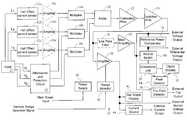
- FIG. 1is a block diagram of the power meter of the present invention.
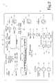
- FIG. 2is an illustration of the face of the power meter of FIG. 1 showing one embodiment of the operator interface.
- An apparatus for measuring electrical power consumption, or the power meter,is illustrated generally at 10 in the figures.
- the poweris measured by multiplying the instantaneous voltage of the load 11 by the instantaneous current of the load 11 to allow for accurate measurement of power consumption for loads 11 having a high supply line frequency.
- the output of the meteris displayed both as a digital representation of the full scale in measurement units selected by the operator and a proportional representation of the scaled instantaneous voltage based on an operator selectable range factor.
- the power meter 10provides scaled and unscaled voltage outputs and a current output for control purposes, high and low trip signals, and a digital interface with external devices for remote control and monitoring.
- FIG. 1illustrates a block diagram of the power meter 10 of the present invention.
- the power meter 10is powered by a universal power supply 46 which automatically adapts to supply voltage (e.g., 110V @ 60 Hz or 220V @ 50Hz) and transforms the supply voltage as necessary.
- the current of the load 11is measured using a Hall Effect current sensor 12 .
- the Hall current sensor 12converts the magnetic field created outside a current-carrying conductor 13 into a voltage signal.
- the Hall Effect current sensor 12processes the measured voltage signal and produces an output voltage signal that is directly proportional to the current flowing through the conductor 13 . This allows the current to be measured indirectly without the need to break conductor 13 and insert an in-line sensor.
- the electrical power consumption for a loadcan be measured for multiple phases by replicating the sensors for each phase.
- the power meter 10is configured for use with a three-phase load 11 .
- the conductor for each phase 13 a - 13 cis routed through a separate Hall Effect current sensor 12 a - 12 c .
- the Hall Effect current sensor 12may be built within the power meter 10 or may be located externally and connected to the power meter 10 via a cable (not shown).
- the voltage and current cablescan be either permanently or removably attached to the power meter 10 .
- Removable attachmentprovides additional flexibility by allowing the use of optional current probes of various current measurement and self-diagnostic capabilities.
- an optional input current amplifier 16is included to amplify the output of the Hall Effect current sensor 12 . Additionally, the input current amplifier 16 compensates for the offset voltages added by the Hall Effect current sensor 12 and the input current amplifier 16 itself. The compensation is achieved by adjusting a variable resistance. The compensated input-current voltage signal is then ready for use to calculate the power consumption of the load 11 .
- the instantaneous voltage of the load 11is obtained at an input voltage attenuation circuit 14 . Because the instantaneous voltage of the load 11 is typically very large compared to the input current voltage, it is necessary to reduce the input voltage proportionally to a level which can be utilized by the discrete components or integrated circuits which calculate the power.
- the attenuation circuit 14includes a separate input for each voltage phase. The attenuation circuit 14 proportionally reduces the input phase-to-phase to a voltage level within the operating input range of a multiplier 18 connected to the attenuation circuit 14 . In the preferred embodiment, the attenuation circuit 14 is designed to accept up to a 600-volt AC RMS phase-to-phase input.
- the attenuation circuit 14includes a protection circuit that protects the power meter 10 from damage.
- a similar arrangementmay be used for DC voltages or AC voltages other than the 600 volts range.
- the input voltage and the input-current voltage of corresponding phasesare multiplied and summed to calculate the instantaneous power.
- the power consumptionbecomes independent of the frequency limitation of the Hall Effect current sensor 12 .
- the power consumption on higher frequency loadscan thus be measured with accuracy.
- the multiplication of the input-current voltage and the input voltageoccurs in a multiplier 18 .
- the power meter 10includes three multipliers 18 a - 18 c , each corresponding to a single phase.
- Each of the three multipliers 18 a - 18 ccombines one phase-matched pair of the input voltage and the corresponding input-current voltage.
- the product of the two voltagesis an AC signal at twice the supply frequency that is proportional to the instantaneous power in that phase.
- the output voltages of the multipliersare summed by the adder 20 to produce a voltage representing the total instantaneous power for all phases. If the phases are balanced in the system, the total instantaneous power is a perfect DC voltage. However, any unbalance in the phases results in the total instantaneous power having an AC component.
- the AC componentdoes not register on a typical voltmeter but will register on a fast bar graph or a fast data acquisition system. It is well known in the art to use filters to remove the unwanted AC component from a DC signal.
- the power meter 10By monitoring the input frequency and controlling the filtering, the power meter 10 is capable of measuring power under all conditions. In addition, it can provide valuable information about load imbalance, which is carried by the power signal.
- the adder 20is not necessary for single phase or DC applications.
- a calibration amplifier 22adjusts the output voltage of the adder 20 such that the output voltage is ten volts (10 V) at full scale.
- a precision isolation amplifier 24isolates the adder output from the display and output portion of the power meter 10 from the high power portion of power meter 10 .
- the isolation amplifier 24provides a barrier having excellent high frequency transient immunity. The barrier characteristics therefore do not affect the signal integrity.
- the output voltage of the isolation amplifier 24represents the total instantaneous power consumption of the attached load 11 and feeds the display and output portion of the power meter 10 .
- the total instantaneous power consumption voltage, or total power voltageis used to provide the operator with information regarding the power usage of the load 11 .
- the power meter 10includes an optional noise filter 26 for reducing noise in the total power voltage resulting from external sources such as load or supply line noise.
- the noise filter 26is a lowpass filter having an adjustable time constant.
- the noise filter time constantcan be controlled either directly by a switch or remotely by an external device without interfering with the objects and advantages of the present invention.
- the filter response switch supplied on the power meter 10is disabled.
- an operator-adjustable main amplifier 28calibrates the full scale output for display.
- a conversion unit 30digitizes the analog input and converts the digital representation to the units selected by the operator, e.g., horsepower (HP) or kilowatts (KW) for display on a visual indicator 32 , such as a numeric LED display 32 .
- the conversion unit 30includes an analog-to-digital converter.
- the preferred embodimentcontains a 32-digit or a 42-digit, 7-segment LED display.
- the peak value of the digital representation of the total poweris sampled and held by a peak detector 34 .
- the peak detector 34obtains the peak value over a time period controlled by the operator, for example, by pressing and holding a button 70 . If desired, the idle power can be subtracted from the total power.
- the peak valueis held and displayed on the LED display 32 for a predetermined period of time or until the operator cancels the peak value display, such as by pressing a reset button 72 .
- the power meter 10also includes a trip point detector 36 .
- the trip point detector 36includes operator selectable high and low trip points.
- each trip pointis handled by a relay which trips when the power reaches a predetermined threshold value, e.g., the power exceeds the selected high trip point or is below the selected low trip point to avoid motor burn-ups or idle power waste.
- the preferred embodimentincludes an operator selectable time delay requiring the power to remain above or below the predetermined threshold for an adjustable, predetermined period of time to prevent false triggers resulting from noise or other sources.
- the trip point detector 36includes a set of potential-free contacts for connecting an external warning or control device.
- the power meter 10further includes a reference value comparator 35 which detects and holds an operator selected reference value, such as the idle power or the normal power in a process or an operation. The reference value is compared to the measured instantaneous power to produce a differential voltage output.
- a source switch 86channels the operator selected input, either the differential voltage output or the measured instantaneous voltage, to the conversion unit 30 .
- the output of the isolation amplifier 24also drives a scaling amplifier, alternately referred to as a range amplifier, 38 for enhancing the sensor range or sensitivity.
- the scaling amplifier 38is an accurate instrumentation amplifier.
- the gain of the scaling amplifier 38is controlled by the operator adjustable range selector 40 .
- the actual rangeis equal to the sensor range divided by range factor selected using the range selector 40 thereby allowing measurement of power at less than or greater than full scale with the desired degree of precision.
- a power meter 10 having a 100-kilowatt full scale sensoris capable of providing displaying precise measurements for a one kilowatt (1 KW) power output full scale by dividing the full scale sensor range by a range factor of 100.
- the range selectorincludes six (6) user selectable range factors: 2, 5, 10, 20, 50, and 100. Those skilled in the art will recognize that other range factors can be used without interfering with the objects and advantages of the present invention.
- the range selector 40is a switch; however, those skilled in the art will recognize that the range selector can also be controlled remotely without interfering with the objects and advantages of the present invention.
- the range selector switch supplied on the power meter 10is disabled.
- the range-adjusted poweris instantaneously displayed on a visual indicator 42 , such as a LED bar display, as a percentage of the range scale selected by the operator, in the resolution of the selected LED bar display 42 .
- the LED bar display 42is a 50-LED bar. Those skilled in the art will recognize that other percentage increments and displays can be used without interfering with the objects and advantages of the present invention.
- the power meter 10includes a scaled external voltage output from the scaling amplifier 38 . Additionally, the power meter 10 includes a current source 44 for converting the scaled voltage from the scaling amplifier 38 to a current for control applications. In the preferred embodiment, the current source 44 is a 4-20 milliamp transmitter. Finally, an unscaled external voltage output is available from the main amplifier 28 and an external differential voltage output is available from the reference power comparator 35 . Those skilled in the art will recognize that the voltage outputs may be amplified and scaled to different values as need to drive LEDs or other displays and control devices without interfering with the objects and advantages of the present invention.
- FIG. 2illustrates one embodiment of the face 48 of the power meter 10 showing the various features and displays available to the operator.
- the power meter 10is configured as a fixed meter associated with a single load 11 .
- the Hall sensors 12 a - 12 care shown as through-openings in the power meter 10 through which current carrying conductors 13 a - 13 c of the load 11 pass.
- the Hall sensorsare hinged probes connected to the power meter 10 via leads.
- Visual indicatorsincluding the digital display 32 for displaying a numeric representation of the total power consumption and the peak power, the bar graph display 42 for graphically displaying a proportional representation of the instantaneous scaled total power consumption in relation to full scale, a power indicator 50 for indicating that the power meter 10 is operating, a high trip indicator 62 and a low trip indicator 64 for indicating that the total power reached the corresponding trip point, and a range indicator 76 for indicating the maximum value at full scale.
- the digital display 32for displaying a numeric representation of the total power consumption and the peak power
- the bar graph display 42for graphically displaying a proportional representation of the instantaneous scaled total power consumption in relation to full scale
- a power indicator 50for indicating that the power meter 10 is operating
- a high trip indicator 62 and a low trip indicator 64for indicating that the total power reached the corresponding trip point
- a range indicator 76for indicating the maximum value at full scale.
- a high trip point selector 54 and a low trip point selector 56for setting the corresponding trip points
- a high trip delay selector 58 and a low trip delay selector 60for setting the period for which the total power must exceed the trip point before a trip occurs
- a measurement unit selector 68for selecting whether the value displayed is in horsepower or kilowatts
- a peak hold switch 70which causes the power meter to store the peak value of the total power
- a peak reset 72for clearing the stored peak value
- a reference power hold switch 90which causes the power meter to store a current power measurement for comparison with a later power measurement
- a reference power reset 88for clearing the stored reference value
- a source selection switch 86for selecting whether the digital display 32 shows the instantaneous power or the differential power
- a range divider selector 74for selecting the appropriate divider by which to scale the total power output to improve the display precision
- a display response selector 78to control the speed at which the bar graph display 42 is updated.
- the face 48also displays a number of inputs and outputs.
- the illustrated embodimentconfigured for use as a fixed position power meter for a three-phase load, includes a plurality of through-openings allowing the load conductors 13 a - 13 c to pass through the internal Hall sensors 12 a - 12 c .
- the face 48also includes a high trip output 63 and a low trip output 65 for providing a control signal to an external device when a trip occurs.
- the face 48includes a scaled voltage output 80 , an unscaled voltage output 82 , and a control current output 84 for providing the power consumption information to an external device for monitoring or controlling a remote system.
- Those skilled in the artwill recognize that other controls, inputs, and output can be used without interfering with the objects and advantages of the present invention.
- the present inventiondoes not require setting of the maximum input current and the maximum input voltage prior to making a measurement. Additionally, the present invention is capable of measuring the power consumption of a load requiring a high frequency power supply without degradation of the measurement accuracy.
- the power meter of the present inventionprovides a display of instantaneous power consumption as a percentage of the scaled measurement range. Further, the present invention provides a display of peak power consumption and operator selectable measurement units. The present invention also simultaneously provides both scaled and unscaled outputs, along with both high and low trip points.
- the power meter of the present inventionis capable of communicating with and responding to external devices. In the preferred embodiment, the interface with external devices is a combination analog and digital interface providing bidirectional communication known to those skilled in the art.
Landscapes
- Engineering & Computer Science (AREA)
- Power Engineering (AREA)
- Physics & Mathematics (AREA)
- General Physics & Mathematics (AREA)
- Remote Monitoring And Control Of Power-Distribution Networks (AREA)
Abstract
Description
| U.S. Pat. No. | Inventor | Issue Date |
| 5,537,029 | Hemminger, R. C., et al. | Jul. 16, 1996 |
| 5,475,303 | Kobayashi, S. | Dec. 12, 1995 |
| 5,467,012 | Nystrom, R. W. | Nov. 14, 1995 |
| 5,438,258 | Maruyama, R. | Aug. 1, 1995 |
| 5,414,349 | Kobayashi, S. | May 9, 1995 |
| 5,003,252 | Nystrom, R. W. | Mar. 26, 1991 |
| 4,764,720 | Nystrom, R. W. | Aug. 16, 1988 |
| 4,535,287 | Milkovic, M. | Aug. 13, 1985 |
Claims (34)
Priority Applications (1)
| Application Number | Priority Date | Filing Date | Title |
|---|---|---|---|
| US09/579,687US6483291B1 (en) | 2000-05-26 | 2000-05-26 | Apparatus for measuring electrical power consumption |
Applications Claiming Priority (1)
| Application Number | Priority Date | Filing Date | Title |
|---|---|---|---|
| US09/579,687US6483291B1 (en) | 2000-05-26 | 2000-05-26 | Apparatus for measuring electrical power consumption |
Publications (1)
| Publication Number | Publication Date |
|---|---|
| US6483291B1true US6483291B1 (en) | 2002-11-19 |
Family
ID=24317924
Family Applications (1)
| Application Number | Title | Priority Date | Filing Date |
|---|---|---|---|
| US09/579,687Expired - LifetimeUS6483291B1 (en) | 2000-05-26 | 2000-05-26 | Apparatus for measuring electrical power consumption |
Country Status (1)
| Country | Link |
|---|---|
| US (1) | US6483291B1 (en) |
Cited By (34)
| Publication number | Priority date | Publication date | Assignee | Title |
|---|---|---|---|---|
| US6636030B1 (en)* | 2001-03-28 | 2003-10-21 | Electro Industries/Gauge Technologies | Revenue grade meter with high-speed transient detection |
| US20040006439A1 (en)* | 2001-06-28 | 2004-01-08 | Hunter Robert R. | Method and apparatus for reading and controlling utility consumption |
| US20040078154A1 (en)* | 2001-06-28 | 2004-04-22 | Hunter Robert R. | Method and apparatus for reading and controlling utility consumption |
| US20040124828A1 (en)* | 2002-12-27 | 2004-07-01 | Dunn Donald Craig | Device and method for continuously monitoring energy usage |
| US20070176933A1 (en)* | 2006-01-20 | 2007-08-02 | Newport Corporation | Self-centering zoom bar graph |
| US20070219732A1 (en)* | 2006-03-14 | 2007-09-20 | Creus Gerard B | Mobile device and method |
| US20090012728A1 (en)* | 2005-01-27 | 2009-01-08 | Electro Industries/Gauge Tech. | System and Method for Multi-Rate Concurrent Waveform Capture and Storage for Power Quality Metering |
| US20090108680A1 (en)* | 2007-10-31 | 2009-04-30 | Kabushiki Kaisha Toshiba | Remote power control system and power supply tap |
| US20100179777A1 (en)* | 2004-10-20 | 2010-07-15 | Electro Industries/Gauge Tech | Test pulses for enabling revenue testable panel meters |
| US20110166719A1 (en)* | 2010-01-05 | 2011-07-07 | Amperic Inc. | Monitoring Power Usage |
| US8116072B2 (en) | 2004-12-03 | 2012-02-14 | Electro Industries/Gauge Tech | Current inputs interface for an electrical device |
| US20120053869A1 (en)* | 2010-08-30 | 2012-03-01 | Owen James E | Delayed Meter Reporting |
| US20130275788A1 (en)* | 2011-03-30 | 2013-10-17 | Kabushiki Kaisha Toshiba | Information processing device, method for calculating degree of contribution to power saving, and presentation method |
| US20130317770A1 (en)* | 2011-02-04 | 2013-11-28 | Fujitsu Component Limited | Power strip and power measurement method |
| US20140210460A1 (en)* | 2013-01-30 | 2014-07-31 | Hampden Kuhns | Contactless electric meter reading devices |
| US8907658B2 (en) | 2012-04-19 | 2014-12-09 | Kohler, Inc. | System and method of measuring power produced by a power source |
| US20160245849A1 (en)* | 2013-11-06 | 2016-08-25 | Zhejiang Shenghui Lighting Co.,Ltd | An electrical circuit and a method for measuring the power consumption of an led lighting device |
| CN106771555A (en)* | 2016-12-14 | 2017-05-31 | 广东威创视讯科技股份有限公司 | A kind of DLP powers observation circuit |
| US9903895B2 (en) | 2005-01-27 | 2018-02-27 | Electro Industries/Gauge Tech | Intelligent electronic device and method thereof |
| US9989618B2 (en) | 2007-04-03 | 2018-06-05 | Electro Industries/Gaugetech | Intelligent electronic device with constant calibration capabilities for high accuracy measurements |
| CN109541273A (en)* | 2018-12-25 | 2019-03-29 | 宁波美星机电有限公司 | A kind of intelligent appliance electric energy metering device |
| US10454390B2 (en)* | 2017-09-26 | 2019-10-22 | Schneider Electric USA, Inc. | Detection of initial motor rotation in mains-fed induction motor |
| US10628053B2 (en) | 2004-10-20 | 2020-04-21 | Electro Industries/Gauge Tech | Intelligent electronic device for receiving and sending data at high speeds over a network |
| US10641618B2 (en) | 2004-10-20 | 2020-05-05 | Electro Industries/Gauge Tech | On-line web accessed energy meter |
| US10845399B2 (en) | 2007-04-03 | 2020-11-24 | Electro Industries/Gaugetech | System and method for performing data transfers in an intelligent electronic device |
| US10921835B1 (en)* | 2012-09-06 | 2021-02-16 | EnTouch Controls Inc. | Wirelessly connected thermostat with flexible and scalable energy reporting |
| US11086346B2 (en)* | 2013-08-28 | 2021-08-10 | San Diego Gas & Electric Company | Managing power source interaction through an interconnect socket adapter configured with an energy storage source/sink |
| US11307227B2 (en) | 2007-04-03 | 2022-04-19 | Electro Industries/Gauge Tech | High speed digital transient waveform detection system and method for use in an intelligent electronic device |
| US11366143B2 (en) | 2005-01-27 | 2022-06-21 | Electro Industries/Gaugetech | Intelligent electronic device with enhanced power quality monitoring and communication capabilities |
| US11366145B2 (en) | 2005-01-27 | 2022-06-21 | Electro Industries/Gauge Tech | Intelligent electronic device with enhanced power quality monitoring and communications capability |
| US11625734B2 (en) | 2013-08-28 | 2023-04-11 | San Diego Gas & Electric Company | Managing grid interaction with interconnect socket adapter configured for an energy storage device |
| US11644490B2 (en) | 2007-04-03 | 2023-05-09 | El Electronics Llc | Digital power metering system with serial peripheral interface (SPI) multimaster communications |
| US11686749B2 (en) | 2004-10-25 | 2023-06-27 | El Electronics Llc | Power meter having multiple ethernet ports |
| US12061218B2 (en) | 2008-03-13 | 2024-08-13 | Ei Electronics Llc | System and method for multi-rate concurrent waveform capture and storage for power quality metering |
Citations (14)
| Publication number | Priority date | Publication date | Assignee | Title |
|---|---|---|---|---|
| US4300182A (en)* | 1979-08-09 | 1981-11-10 | Schweitzer Edmund O Iii | Metering and protection system for an A.C. power system |
| US4535287A (en)* | 1983-03-25 | 1985-08-13 | General Electric Company | Electronic watt/watthour meter with automatic error correction and high frequency digital output |
| US4700188A (en)* | 1985-01-29 | 1987-10-13 | Micronic Interface Technologies | Electric power measurement system and hall effect based electric power meter for use therein |
| US4764720A (en)* | 1985-12-05 | 1988-08-16 | Load Controls Incorporated | Apparatus and method for measuring variable frequency power |
| US4884021A (en)* | 1987-04-24 | 1989-11-28 | Transdata, Inc. | Digital power metering |
| US5003252A (en)* | 1989-08-16 | 1991-03-26 | Load Controls Incorporated | Apparatus and method for measuring power factor and torque on the output of variable frequency drives |
| US5122735A (en)* | 1990-06-14 | 1992-06-16 | Transdata, Inc. | Digital power metering |
| US5319300A (en)* | 1993-05-24 | 1994-06-07 | Sylvester Wood | Error compensating circuit for power consumption meter |
| US5352962A (en)* | 1993-04-19 | 1994-10-04 | Sug Lithography Systems, Inc. | Brushless polyphase reduced force variation motor |
| US5414349A (en)* | 1991-11-21 | 1995-05-09 | Kabushiki Kaisha Toshiba | Electronic watthour meter |
| US5438258A (en)* | 1992-12-11 | 1995-08-01 | Kabushiki Kaisha Toshiba | Power multiplication circuit which reduces an offset voltage of a Hall element to zero |
| US5467012A (en)* | 1994-05-10 | 1995-11-14 | Load Controls Incorporated | Power monitoring |
| US5485393A (en)* | 1990-08-30 | 1996-01-16 | Metricom, Inc. | Method and apparatus for measuring electrical parameters using a differentiating current sensor and a digital integrator |
| US5537029A (en)* | 1992-02-21 | 1996-07-16 | Abb Power T&D Company Inc. | Method and apparatus for electronic meter testing |
- 2000
- 2000-05-26USUS09/579,687patent/US6483291B1/ennot_activeExpired - Lifetime
Patent Citations (15)
| Publication number | Priority date | Publication date | Assignee | Title |
|---|---|---|---|---|
| US4300182A (en)* | 1979-08-09 | 1981-11-10 | Schweitzer Edmund O Iii | Metering and protection system for an A.C. power system |
| US4535287A (en)* | 1983-03-25 | 1985-08-13 | General Electric Company | Electronic watt/watthour meter with automatic error correction and high frequency digital output |
| US4700188A (en)* | 1985-01-29 | 1987-10-13 | Micronic Interface Technologies | Electric power measurement system and hall effect based electric power meter for use therein |
| US4764720A (en)* | 1985-12-05 | 1988-08-16 | Load Controls Incorporated | Apparatus and method for measuring variable frequency power |
| US4884021A (en)* | 1987-04-24 | 1989-11-28 | Transdata, Inc. | Digital power metering |
| US5003252A (en)* | 1989-08-16 | 1991-03-26 | Load Controls Incorporated | Apparatus and method for measuring power factor and torque on the output of variable frequency drives |
| US5122735A (en)* | 1990-06-14 | 1992-06-16 | Transdata, Inc. | Digital power metering |
| US5485393A (en)* | 1990-08-30 | 1996-01-16 | Metricom, Inc. | Method and apparatus for measuring electrical parameters using a differentiating current sensor and a digital integrator |
| US5414349A (en)* | 1991-11-21 | 1995-05-09 | Kabushiki Kaisha Toshiba | Electronic watthour meter |
| US5475303A (en)* | 1991-11-21 | 1995-12-12 | Kabushiki Kaisha Toshiba | Electronic watthour meter |
| US5537029A (en)* | 1992-02-21 | 1996-07-16 | Abb Power T&D Company Inc. | Method and apparatus for electronic meter testing |
| US5438258A (en)* | 1992-12-11 | 1995-08-01 | Kabushiki Kaisha Toshiba | Power multiplication circuit which reduces an offset voltage of a Hall element to zero |
| US5352962A (en)* | 1993-04-19 | 1994-10-04 | Sug Lithography Systems, Inc. | Brushless polyphase reduced force variation motor |
| US5319300A (en)* | 1993-05-24 | 1994-06-07 | Sylvester Wood | Error compensating circuit for power consumption meter |
| US5467012A (en)* | 1994-05-10 | 1995-11-14 | Load Controls Incorporated | Power monitoring |
Cited By (51)
| Publication number | Priority date | Publication date | Assignee | Title |
|---|---|---|---|---|
| US6636030B1 (en)* | 2001-03-28 | 2003-10-21 | Electro Industries/Gauge Technologies | Revenue grade meter with high-speed transient detection |
| US7039532B2 (en)* | 2001-06-28 | 2006-05-02 | Hunter Robert R | Method and apparatus for reading and controlling utility consumption |
| US20040006439A1 (en)* | 2001-06-28 | 2004-01-08 | Hunter Robert R. | Method and apparatus for reading and controlling utility consumption |
| US20040078154A1 (en)* | 2001-06-28 | 2004-04-22 | Hunter Robert R. | Method and apparatus for reading and controlling utility consumption |
| US7263450B2 (en) | 2001-06-28 | 2007-08-28 | Hunter Robert R | Method and apparatus for reading and controlling electric power consumption |
| US20050096857A1 (en)* | 2001-06-28 | 2005-05-05 | Hunter Robert R. | Method and apparatus for reading and controlling electric power consumption |
| US20040124828A1 (en)* | 2002-12-27 | 2004-07-01 | Dunn Donald Craig | Device and method for continuously monitoring energy usage |
| WO2004061461A1 (en)* | 2002-12-27 | 2004-07-22 | Donald Craig Dunn | Device and method for continuously monitoring energy usage |
| US10628053B2 (en) | 2004-10-20 | 2020-04-21 | Electro Industries/Gauge Tech | Intelligent electronic device for receiving and sending data at high speeds over a network |
| US10641618B2 (en) | 2004-10-20 | 2020-05-05 | Electro Industries/Gauge Tech | On-line web accessed energy meter |
| US20100179777A1 (en)* | 2004-10-20 | 2010-07-15 | Electro Industries/Gauge Tech | Test pulses for enabling revenue testable panel meters |
| US11754418B2 (en) | 2004-10-20 | 2023-09-12 | Ei Electronics Llc | On-line web accessed energy meter |
| US11686749B2 (en) | 2004-10-25 | 2023-06-27 | El Electronics Llc | Power meter having multiple ethernet ports |
| US8116072B2 (en) | 2004-12-03 | 2012-02-14 | Electro Industries/Gauge Tech | Current inputs interface for an electrical device |
| US20090012728A1 (en)* | 2005-01-27 | 2009-01-08 | Electro Industries/Gauge Tech. | System and Method for Multi-Rate Concurrent Waveform Capture and Storage for Power Quality Metering |
| US10823770B2 (en) | 2005-01-27 | 2020-11-03 | Electro Industries/Gaugetech | Intelligent electronic device and method thereof |
| US9903895B2 (en) | 2005-01-27 | 2018-02-27 | Electro Industries/Gauge Tech | Intelligent electronic device and method thereof |
| US8121801B2 (en) | 2005-01-27 | 2012-02-21 | Electro Industries/Gauge Tech | System and method for multi-rate concurrent waveform capture and storage for power quality metering |
| US11366145B2 (en) | 2005-01-27 | 2022-06-21 | Electro Industries/Gauge Tech | Intelligent electronic device with enhanced power quality monitoring and communications capability |
| US11366143B2 (en) | 2005-01-27 | 2022-06-21 | Electro Industries/Gaugetech | Intelligent electronic device with enhanced power quality monitoring and communication capabilities |
| US8004527B2 (en)* | 2006-01-20 | 2011-08-23 | Newport Corporation | Self-centering zoom bar graph |
| US8194076B2 (en)* | 2006-01-20 | 2012-06-05 | Newport Corporation | Auto-scaling strip chart |
| US20110273478A1 (en)* | 2006-01-20 | 2011-11-10 | Newport Corporation | Auto-scaling strip chart |
| US20070176933A1 (en)* | 2006-01-20 | 2007-08-02 | Newport Corporation | Self-centering zoom bar graph |
| US20070219732A1 (en)* | 2006-03-14 | 2007-09-20 | Creus Gerard B | Mobile device and method |
| US9407747B2 (en)* | 2006-03-14 | 2016-08-02 | Nokia Technologies Oy | Mobile device and method |
| US11635455B2 (en) | 2007-04-03 | 2023-04-25 | El Electronics Llc | System and method for performing data transfers in an intelligent electronic device |
| US11644490B2 (en) | 2007-04-03 | 2023-05-09 | El Electronics Llc | Digital power metering system with serial peripheral interface (SPI) multimaster communications |
| US11307227B2 (en) | 2007-04-03 | 2022-04-19 | Electro Industries/Gauge Tech | High speed digital transient waveform detection system and method for use in an intelligent electronic device |
| US10845399B2 (en) | 2007-04-03 | 2020-11-24 | Electro Industries/Gaugetech | System and method for performing data transfers in an intelligent electronic device |
| US9989618B2 (en) | 2007-04-03 | 2018-06-05 | Electro Industries/Gaugetech | Intelligent electronic device with constant calibration capabilities for high accuracy measurements |
| US20090108680A1 (en)* | 2007-10-31 | 2009-04-30 | Kabushiki Kaisha Toshiba | Remote power control system and power supply tap |
| US8401587B2 (en) | 2007-10-31 | 2013-03-19 | Kabushiki Kaisha Toshiba | Remote power control system and power supply tap |
| US12061218B2 (en) | 2008-03-13 | 2024-08-13 | Ei Electronics Llc | System and method for multi-rate concurrent waveform capture and storage for power quality metering |
| US8648607B2 (en) | 2010-01-05 | 2014-02-11 | Amperic, Inc. | Monitoring power usage |
| US20110166719A1 (en)* | 2010-01-05 | 2011-07-07 | Amperic Inc. | Monitoring Power Usage |
| US20120053869A1 (en)* | 2010-08-30 | 2012-03-01 | Owen James E | Delayed Meter Reporting |
| US9213050B2 (en)* | 2010-08-30 | 2015-12-15 | Sharp Laboratories Of America, Inc. | Delayed meter reporting |
| US9316672B2 (en)* | 2011-02-04 | 2016-04-19 | Fujitsu Limited | Power strip and power measurement method |
| US20130317770A1 (en)* | 2011-02-04 | 2013-11-28 | Fujitsu Component Limited | Power strip and power measurement method |
| US20130275788A1 (en)* | 2011-03-30 | 2013-10-17 | Kabushiki Kaisha Toshiba | Information processing device, method for calculating degree of contribution to power saving, and presentation method |
| US8907658B2 (en) | 2012-04-19 | 2014-12-09 | Kohler, Inc. | System and method of measuring power produced by a power source |
| US10921835B1 (en)* | 2012-09-06 | 2021-02-16 | EnTouch Controls Inc. | Wirelessly connected thermostat with flexible and scalable energy reporting |
| US20140210460A1 (en)* | 2013-01-30 | 2014-07-31 | Hampden Kuhns | Contactless electric meter reading devices |
| US11086346B2 (en)* | 2013-08-28 | 2021-08-10 | San Diego Gas & Electric Company | Managing power source interaction through an interconnect socket adapter configured with an energy storage source/sink |
| US11625734B2 (en) | 2013-08-28 | 2023-04-11 | San Diego Gas & Electric Company | Managing grid interaction with interconnect socket adapter configured for an energy storage device |
| US9791483B2 (en)* | 2013-11-06 | 2017-10-17 | Zhejiang Shenghui Lighting Co., Ltd | Electrical circuit and a method for measuring the power consumption of an LED lighting device |
| US20160245849A1 (en)* | 2013-11-06 | 2016-08-25 | Zhejiang Shenghui Lighting Co.,Ltd | An electrical circuit and a method for measuring the power consumption of an led lighting device |
| CN106771555A (en)* | 2016-12-14 | 2017-05-31 | 广东威创视讯科技股份有限公司 | A kind of DLP powers observation circuit |
| US10454390B2 (en)* | 2017-09-26 | 2019-10-22 | Schneider Electric USA, Inc. | Detection of initial motor rotation in mains-fed induction motor |
| CN109541273A (en)* | 2018-12-25 | 2019-03-29 | 宁波美星机电有限公司 | A kind of intelligent appliance electric energy metering device |
Similar Documents
| Publication | Publication Date | Title |
|---|---|---|
| US6483291B1 (en) | Apparatus for measuring electrical power consumption | |
| CA1269713A (en) | Electronic electricity meters | |
| CA2148075C (en) | High accuracy power monitor and method | |
| US6026355A (en) | Solid state watt-hour meter using GMR sensor | |
| CA1244084A (en) | Portable tester and related method for determining the primary winding to secondary winding current ratio of an in-service current transformer | |
| US5124624A (en) | Arrangement for electrical measurement | |
| US3995210A (en) | Variable gain electronic current transformer | |
| EP2642303A1 (en) | Independently packaged electric meter sensor | |
| US5144226A (en) | Multi-mode measuring system | |
| US4829239A (en) | Multimeter | |
| KR100259187B1 (en) | Error compensation apparatus of electronic watt-hour meter | |
| US4754219A (en) | Low cost self-contained transformerless solid state electronic watthour meter having thin film ferromagnetic current sensor | |
| CA1046584A (en) | Variable gain electronic current transformer | |
| US4209741A (en) | Apparatus for the continuous monitoring of ground bed resistance | |
| US4283678A (en) | Cable condition analyzing system for electric arc furnace conductors | |
| CN109307839B (en) | Circuit for Testing Contact Voltage Drop During the Electrical Life Experiment of AC Appliances | |
| CA2777413C (en) | Selectable delta or wye voltage configuration for power measurement | |
| CN213398688U (en) | Multifunctional tester and testing system | |
| KR100194550B1 (en) | Measuring device and method for load control of column transformer | |
| KR20070107453A (en) | Insulation Monitoring System | |
| RU2313799C1 (en) | Mode of controlling reduction of resistance of insulation in a line of feeding voltage to a load and an arrangement for its execution | |
| KR200175333Y1 (en) | Measuring instrument of line load at recloser in distribution line | |
| JPH0652277B2 (en) | Standard device with calculation function | |
| RU2234707C1 (en) | Device for measuring electrical energy with protection from thefts | |
| JP2004226094A (en) | Electronic watt-hour meter |
Legal Events
| Date | Code | Title | Description |
|---|---|---|---|
| STCF | Information on status: patent grant | Free format text:PATENTED CASE | |
| FPAY | Fee payment | Year of fee payment:4 | |
| AS | Assignment | Owner name:ANR, LP, TENNESSEE Free format text:ASSIGNMENT OF ASSIGNORS INTEREST;ASSIGNORS:BHATEJA, CHANDER P.;BHATEJA, RAJIV K.;REEL/FRAME:018303/0923;SIGNING DATES FROM 20060923 TO 20060924 | |
| AS | Assignment | Owner name:ANR, LP, TENNESSEE Free format text:ASSIGNMENT OF ASSIGNORS INTEREST;ASSIGNOR:RANKO, LLC;REEL/FRAME:021339/0940 Effective date:20080806 | |
| AS | Assignment | Owner name:RANKO IP SERIES OF RANKO, LLC, TENNESSEE Free format text:ASSIGNMENT OF ASSIGNORS INTEREST;ASSIGNOR:ANR, LP;REEL/FRAME:021876/0374 Effective date:20081124 | |
| FPAY | Fee payment | Year of fee payment:8 | |
| AS | Assignment | Owner name:RANKO IP SERIES OF RANKO, LLC, TENNESSEE Free format text:ASSIGNMENT OF ASSIGNORS INTEREST;ASSIGNOR:ANR, LP;REEL/FRAME:025615/0845 Effective date:20100413 | |
| FPAY | Fee payment | Year of fee payment:12 |