US6483198B2 - Hybrid electric vehicle having a selective zero emission mode, and method of selectively operating the zero emission mode - Google Patents
Hybrid electric vehicle having a selective zero emission mode, and method of selectively operating the zero emission modeDownload PDFInfo
- Publication number
- US6483198B2 US6483198B2US09/764,357US76435701AUS6483198B2US 6483198 B2US6483198 B2US 6483198B2US 76435701 AUS76435701 AUS 76435701AUS 6483198 B2US6483198 B2US 6483198B2
- Authority
- US
- United States
- Prior art keywords
- vehicle
- generator
- zone
- internal combustion
- combustion engine
- Prior art date
- Legal status (The legal status is an assumption and is not a legal conclusion. Google has not performed a legal analysis and makes no representation as to the accuracy of the status listed.)
- Expired - Lifetime, expires
Links
Images


Classifications
- B—PERFORMING OPERATIONS; TRANSPORTING
- B60—VEHICLES IN GENERAL
- B60W—CONJOINT CONTROL OF VEHICLE SUB-UNITS OF DIFFERENT TYPE OR DIFFERENT FUNCTION; CONTROL SYSTEMS SPECIALLY ADAPTED FOR HYBRID VEHICLES; ROAD VEHICLE DRIVE CONTROL SYSTEMS FOR PURPOSES NOT RELATED TO THE CONTROL OF A PARTICULAR SUB-UNIT
- B60W20/00—Control systems specially adapted for hybrid vehicles
- B—PERFORMING OPERATIONS; TRANSPORTING
- B60—VEHICLES IN GENERAL
- B60K—ARRANGEMENT OR MOUNTING OF PROPULSION UNITS OR OF TRANSMISSIONS IN VEHICLES; ARRANGEMENT OR MOUNTING OF PLURAL DIVERSE PRIME-MOVERS IN VEHICLES; AUXILIARY DRIVES FOR VEHICLES; INSTRUMENTATION OR DASHBOARDS FOR VEHICLES; ARRANGEMENTS IN CONNECTION WITH COOLING, AIR INTAKE, GAS EXHAUST OR FUEL SUPPLY OF PROPULSION UNITS IN VEHICLES
- B60K6/00—Arrangement or mounting of plural diverse prime-movers for mutual or common propulsion, e.g. hybrid propulsion systems comprising electric motors and internal combustion engines
- B60K6/20—Arrangement or mounting of plural diverse prime-movers for mutual or common propulsion, e.g. hybrid propulsion systems comprising electric motors and internal combustion engines the prime-movers consisting of electric motors and internal combustion engines, e.g. HEVs
- B60K6/42—Arrangement or mounting of plural diverse prime-movers for mutual or common propulsion, e.g. hybrid propulsion systems comprising electric motors and internal combustion engines the prime-movers consisting of electric motors and internal combustion engines, e.g. HEVs characterised by the architecture of the hybrid electric vehicle
- B60K6/46—Series type
- B—PERFORMING OPERATIONS; TRANSPORTING
- B60—VEHICLES IN GENERAL
- B60L—PROPULSION OF ELECTRICALLY-PROPELLED VEHICLES; SUPPLYING ELECTRIC POWER FOR AUXILIARY EQUIPMENT OF ELECTRICALLY-PROPELLED VEHICLES; ELECTRODYNAMIC BRAKE SYSTEMS FOR VEHICLES IN GENERAL; MAGNETIC SUSPENSION OR LEVITATION FOR VEHICLES; MONITORING OPERATING VARIABLES OF ELECTRICALLY-PROPELLED VEHICLES; ELECTRIC SAFETY DEVICES FOR ELECTRICALLY-PROPELLED VEHICLES
- B60L50/00—Electric propulsion with power supplied within the vehicle
- B60L50/50—Electric propulsion with power supplied within the vehicle using propulsion power supplied by batteries or fuel cells
- B60L50/60—Electric propulsion with power supplied within the vehicle using propulsion power supplied by batteries or fuel cells using power supplied by batteries
- B60L50/61—Electric propulsion with power supplied within the vehicle using propulsion power supplied by batteries or fuel cells using power supplied by batteries by batteries charged by engine-driven generators, e.g. series hybrid electric vehicles
- B—PERFORMING OPERATIONS; TRANSPORTING
- B60—VEHICLES IN GENERAL
- B60W—CONJOINT CONTROL OF VEHICLE SUB-UNITS OF DIFFERENT TYPE OR DIFFERENT FUNCTION; CONTROL SYSTEMS SPECIALLY ADAPTED FOR HYBRID VEHICLES; ROAD VEHICLE DRIVE CONTROL SYSTEMS FOR PURPOSES NOT RELATED TO THE CONTROL OF A PARTICULAR SUB-UNIT
- B60W10/00—Conjoint control of vehicle sub-units of different type or different function
- B60W10/04—Conjoint control of vehicle sub-units of different type or different function including control of propulsion units
- B60W10/06—Conjoint control of vehicle sub-units of different type or different function including control of propulsion units including control of combustion engines
- B—PERFORMING OPERATIONS; TRANSPORTING
- B60—VEHICLES IN GENERAL
- B60W—CONJOINT CONTROL OF VEHICLE SUB-UNITS OF DIFFERENT TYPE OR DIFFERENT FUNCTION; CONTROL SYSTEMS SPECIALLY ADAPTED FOR HYBRID VEHICLES; ROAD VEHICLE DRIVE CONTROL SYSTEMS FOR PURPOSES NOT RELATED TO THE CONTROL OF A PARTICULAR SUB-UNIT
- B60W10/00—Conjoint control of vehicle sub-units of different type or different function
- B60W10/04—Conjoint control of vehicle sub-units of different type or different function including control of propulsion units
- B60W10/08—Conjoint control of vehicle sub-units of different type or different function including control of propulsion units including control of electric propulsion units, e.g. motors or generators
- B—PERFORMING OPERATIONS; TRANSPORTING
- B60—VEHICLES IN GENERAL
- B60L—PROPULSION OF ELECTRICALLY-PROPELLED VEHICLES; SUPPLYING ELECTRIC POWER FOR AUXILIARY EQUIPMENT OF ELECTRICALLY-PROPELLED VEHICLES; ELECTRODYNAMIC BRAKE SYSTEMS FOR VEHICLES IN GENERAL; MAGNETIC SUSPENSION OR LEVITATION FOR VEHICLES; MONITORING OPERATING VARIABLES OF ELECTRICALLY-PROPELLED VEHICLES; ELECTRIC SAFETY DEVICES FOR ELECTRICALLY-PROPELLED VEHICLES
- B60L2210/00—Converter types
- B60L2210/30—AC to DC converters
- B—PERFORMING OPERATIONS; TRANSPORTING
- B60—VEHICLES IN GENERAL
- B60L—PROPULSION OF ELECTRICALLY-PROPELLED VEHICLES; SUPPLYING ELECTRIC POWER FOR AUXILIARY EQUIPMENT OF ELECTRICALLY-PROPELLED VEHICLES; ELECTRODYNAMIC BRAKE SYSTEMS FOR VEHICLES IN GENERAL; MAGNETIC SUSPENSION OR LEVITATION FOR VEHICLES; MONITORING OPERATING VARIABLES OF ELECTRICALLY-PROPELLED VEHICLES; ELECTRIC SAFETY DEVICES FOR ELECTRICALLY-PROPELLED VEHICLES
- B60L2210/00—Converter types
- B60L2210/40—DC to AC converters
- B—PERFORMING OPERATIONS; TRANSPORTING
- B60—VEHICLES IN GENERAL
- B60L—PROPULSION OF ELECTRICALLY-PROPELLED VEHICLES; SUPPLYING ELECTRIC POWER FOR AUXILIARY EQUIPMENT OF ELECTRICALLY-PROPELLED VEHICLES; ELECTRODYNAMIC BRAKE SYSTEMS FOR VEHICLES IN GENERAL; MAGNETIC SUSPENSION OR LEVITATION FOR VEHICLES; MONITORING OPERATING VARIABLES OF ELECTRICALLY-PROPELLED VEHICLES; ELECTRIC SAFETY DEVICES FOR ELECTRICALLY-PROPELLED VEHICLES
- B60L2220/00—Electrical machine types; Structures or applications thereof
- B60L2220/10—Electrical machine types
- B60L2220/14—Synchronous machines
- B—PERFORMING OPERATIONS; TRANSPORTING
- B60—VEHICLES IN GENERAL
- B60L—PROPULSION OF ELECTRICALLY-PROPELLED VEHICLES; SUPPLYING ELECTRIC POWER FOR AUXILIARY EQUIPMENT OF ELECTRICALLY-PROPELLED VEHICLES; ELECTRODYNAMIC BRAKE SYSTEMS FOR VEHICLES IN GENERAL; MAGNETIC SUSPENSION OR LEVITATION FOR VEHICLES; MONITORING OPERATING VARIABLES OF ELECTRICALLY-PROPELLED VEHICLES; ELECTRIC SAFETY DEVICES FOR ELECTRICALLY-PROPELLED VEHICLES
- B60L2220/00—Electrical machine types; Structures or applications thereof
- B60L2220/10—Electrical machine types
- B60L2220/16—DC brushless machines
- B—PERFORMING OPERATIONS; TRANSPORTING
- B60—VEHICLES IN GENERAL
- B60L—PROPULSION OF ELECTRICALLY-PROPELLED VEHICLES; SUPPLYING ELECTRIC POWER FOR AUXILIARY EQUIPMENT OF ELECTRICALLY-PROPELLED VEHICLES; ELECTRODYNAMIC BRAKE SYSTEMS FOR VEHICLES IN GENERAL; MAGNETIC SUSPENSION OR LEVITATION FOR VEHICLES; MONITORING OPERATING VARIABLES OF ELECTRICALLY-PROPELLED VEHICLES; ELECTRIC SAFETY DEVICES FOR ELECTRICALLY-PROPELLED VEHICLES
- B60L2240/00—Control parameters of input or output; Target parameters
- B60L2240/10—Vehicle control parameters
- B60L2240/36—Temperature of vehicle components or parts
- B—PERFORMING OPERATIONS; TRANSPORTING
- B60—VEHICLES IN GENERAL
- B60L—PROPULSION OF ELECTRICALLY-PROPELLED VEHICLES; SUPPLYING ELECTRIC POWER FOR AUXILIARY EQUIPMENT OF ELECTRICALLY-PROPELLED VEHICLES; ELECTRODYNAMIC BRAKE SYSTEMS FOR VEHICLES IN GENERAL; MAGNETIC SUSPENSION OR LEVITATION FOR VEHICLES; MONITORING OPERATING VARIABLES OF ELECTRICALLY-PROPELLED VEHICLES; ELECTRIC SAFETY DEVICES FOR ELECTRICALLY-PROPELLED VEHICLES
- B60L2240/00—Control parameters of input or output; Target parameters
- B60L2240/40—Drive Train control parameters
- B60L2240/42—Drive Train control parameters related to electric machines
- B60L2240/425—Temperature
- B—PERFORMING OPERATIONS; TRANSPORTING
- B60—VEHICLES IN GENERAL
- B60L—PROPULSION OF ELECTRICALLY-PROPELLED VEHICLES; SUPPLYING ELECTRIC POWER FOR AUXILIARY EQUIPMENT OF ELECTRICALLY-PROPELLED VEHICLES; ELECTRODYNAMIC BRAKE SYSTEMS FOR VEHICLES IN GENERAL; MAGNETIC SUSPENSION OR LEVITATION FOR VEHICLES; MONITORING OPERATING VARIABLES OF ELECTRICALLY-PROPELLED VEHICLES; ELECTRIC SAFETY DEVICES FOR ELECTRICALLY-PROPELLED VEHICLES
- B60L2240/00—Control parameters of input or output; Target parameters
- B60L2240/40—Drive Train control parameters
- B60L2240/44—Drive Train control parameters related to combustion engines
- B60L2240/445—Temperature
- B—PERFORMING OPERATIONS; TRANSPORTING
- B60—VEHICLES IN GENERAL
- B60W—CONJOINT CONTROL OF VEHICLE SUB-UNITS OF DIFFERENT TYPE OR DIFFERENT FUNCTION; CONTROL SYSTEMS SPECIALLY ADAPTED FOR HYBRID VEHICLES; ROAD VEHICLE DRIVE CONTROL SYSTEMS FOR PURPOSES NOT RELATED TO THE CONTROL OF A PARTICULAR SUB-UNIT
- B60W2510/00—Input parameters relating to a particular sub-units
- B60W2510/24—Energy storage means
- B60W2510/242—Energy storage means for electrical energy
- B60W2510/244—Charge state
- Y—GENERAL TAGGING OF NEW TECHNOLOGICAL DEVELOPMENTS; GENERAL TAGGING OF CROSS-SECTIONAL TECHNOLOGIES SPANNING OVER SEVERAL SECTIONS OF THE IPC; TECHNICAL SUBJECTS COVERED BY FORMER USPC CROSS-REFERENCE ART COLLECTIONS [XRACs] AND DIGESTS
- Y02—TECHNOLOGIES OR APPLICATIONS FOR MITIGATION OR ADAPTATION AGAINST CLIMATE CHANGE
- Y02T—CLIMATE CHANGE MITIGATION TECHNOLOGIES RELATED TO TRANSPORTATION
- Y02T10/00—Road transport of goods or passengers
- Y02T10/60—Other road transportation technologies with climate change mitigation effect
- Y02T10/62—Hybrid vehicles
- Y—GENERAL TAGGING OF NEW TECHNOLOGICAL DEVELOPMENTS; GENERAL TAGGING OF CROSS-SECTIONAL TECHNOLOGIES SPANNING OVER SEVERAL SECTIONS OF THE IPC; TECHNICAL SUBJECTS COVERED BY FORMER USPC CROSS-REFERENCE ART COLLECTIONS [XRACs] AND DIGESTS
- Y02—TECHNOLOGIES OR APPLICATIONS FOR MITIGATION OR ADAPTATION AGAINST CLIMATE CHANGE
- Y02T—CLIMATE CHANGE MITIGATION TECHNOLOGIES RELATED TO TRANSPORTATION
- Y02T10/00—Road transport of goods or passengers
- Y02T10/60—Other road transportation technologies with climate change mitigation effect
- Y02T10/64—Electric machine technologies in electromobility
- Y—GENERAL TAGGING OF NEW TECHNOLOGICAL DEVELOPMENTS; GENERAL TAGGING OF CROSS-SECTIONAL TECHNOLOGIES SPANNING OVER SEVERAL SECTIONS OF THE IPC; TECHNICAL SUBJECTS COVERED BY FORMER USPC CROSS-REFERENCE ART COLLECTIONS [XRACs] AND DIGESTS
- Y02—TECHNOLOGIES OR APPLICATIONS FOR MITIGATION OR ADAPTATION AGAINST CLIMATE CHANGE
- Y02T—CLIMATE CHANGE MITIGATION TECHNOLOGIES RELATED TO TRANSPORTATION
- Y02T10/00—Road transport of goods or passengers
- Y02T10/60—Other road transportation technologies with climate change mitigation effect
- Y02T10/70—Energy storage systems for electromobility, e.g. batteries
- Y—GENERAL TAGGING OF NEW TECHNOLOGICAL DEVELOPMENTS; GENERAL TAGGING OF CROSS-SECTIONAL TECHNOLOGIES SPANNING OVER SEVERAL SECTIONS OF THE IPC; TECHNICAL SUBJECTS COVERED BY FORMER USPC CROSS-REFERENCE ART COLLECTIONS [XRACs] AND DIGESTS
- Y02—TECHNOLOGIES OR APPLICATIONS FOR MITIGATION OR ADAPTATION AGAINST CLIMATE CHANGE
- Y02T—CLIMATE CHANGE MITIGATION TECHNOLOGIES RELATED TO TRANSPORTATION
- Y02T10/00—Road transport of goods or passengers
- Y02T10/60—Other road transportation technologies with climate change mitigation effect
- Y02T10/7072—Electromobility specific charging systems or methods for batteries, ultracapacitors, supercapacitors or double-layer capacitors
- Y—GENERAL TAGGING OF NEW TECHNOLOGICAL DEVELOPMENTS; GENERAL TAGGING OF CROSS-SECTIONAL TECHNOLOGIES SPANNING OVER SEVERAL SECTIONS OF THE IPC; TECHNICAL SUBJECTS COVERED BY FORMER USPC CROSS-REFERENCE ART COLLECTIONS [XRACs] AND DIGESTS
- Y02—TECHNOLOGIES OR APPLICATIONS FOR MITIGATION OR ADAPTATION AGAINST CLIMATE CHANGE
- Y02T—CLIMATE CHANGE MITIGATION TECHNOLOGIES RELATED TO TRANSPORTATION
- Y02T10/00—Road transport of goods or passengers
- Y02T10/60—Other road transportation technologies with climate change mitigation effect
- Y02T10/72—Electric energy management in electromobility
Definitions
- the inventionrelates to methods and apparatus for adaptively controlling a series hybrid electric vehicle to obtain selected zero emission control.
- Compressed natural gashas been used as an alternative fuel. Compressed natural gas does not produce as much power in conventional internal combustion engines as gasoline and diesel and has not been widely developed or accepted as an alternative to gasoline and diesel.
- Additiveshave also been developed for mixing with gasoline to reduce emissions. Ethanol and MTBE have been added to gasoline to oxygenate the combustion of gasoline and reduce emissions of carbon monoxide. These additives, however, are believed to cause decreased gas mileage and, in the case of MTBE, to be a potential public health threat.
- Electric vehicleshave been developed that produce zero emissions. Electric vehicles are propelled by an electric motor that is powered by a battery array on board the vehicle. The range of electric vehicles is limited as the size of the battery array which can be installed on the vehicle is limited. Recharging of the batteries can only be done by connecting the battery array to a power source. Electric vehicles are not truly zero emitters when the electricity to charge the battery array is produced by a power plant that bums, for example, coal.
- Hybrid electric vehicleshave also been developed to reduce emissions.
- Hybrid electric vehiclesinclude an internal combustion engine and at least one electric motor powered by a battery array.
- both the internal combustion engine and the electric motorare coupled to the drive train via mechanical means.
- the electric motormay be used to propel the vehicle at low speeds and to assist the internal combustion engine at higher speeds.
- the electric motormay also be driven, in part, by the internal combustion engine and be operated as a generator to recharge the battery array.
- the internal combustion engineIn a series type hybrid electric vehicle, the internal combustion engine is used only to run a generator that charges the battery array. There is no mechanical connection of the internal combustion engine to the vehicle drive train.
- the electric traction drive motoris powered by the battery array and is mechanically connected to the vehicle drive train.
- the inventionprovides methods and apparatus for adaptively managing the internal combustion engine, generator, and electric motor to produce zero emissions for a series type hybrid electric vehicle.
- An exemplary embodiment of a series type hybrid electric vehicle according to the inventionis controlled so that a generator set of the vehicle, including an internal combustion engine connected to a generator, creates zero emissions within a zero emission zone.
- the internal combustion engine and generatorincrease the electrical charge of the battery array to a predetermined electrical level and are eventually turned off to prevent emissions from entering the zero emission zone.
- the internal combustion engine and generatorare warmed to a predetermined thermal level for a full capacity operation. When the internal combustion engine and generator reach the predetermined thermal level, they operate at full capacity to bring the electrical charge of the battery array to a predetermined electrical level. Thereafter, the vehicle operates under a normal operation.
- a method for adaptively controlling the state of charge of a battery array of a series type hybrid electric vehicle having an internal combustion engine connected to a generator and at least one electric motor propelling the vehicle through the zoneincludes determining a zone, turning off the internal combustion engine and the generator before entering the zone, and turning on the internal combustion engine and the generator after leaving the zone.
- a series type hybrid electric vehicleincludes an internal combustion engine connected to a generator, a battery array receiving current at least from the generator, at least one electric motor receiving current from the battery array, the motor propelling the vehicle, and a controller that determines a zone, turns off the internal combustion engine and the generator before entering the zone, and turns on the internal combustion engine and the generator after leaving the zone.
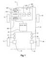
- FIG. 1is schematic view of an exemplary embodiment of a series hybrid electric vehicle according to the invention
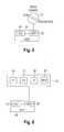
- FIG. 2is a schematic diagram illustrating an exemplary embodiment of a circuit for controlling charging of the battery array by the generator
- FIG. 3is a diagram illustrating an exemplary embodiment of a circuit for controlling the electric motors
- FIG. 4is a diagram illustrating an exemplary embodiment of a circuit of the motor controllers
- FIG. 5is a diagram illustrating an exemplary embodiment of a master control switch
- FIG. 6is a diagram illustrating an exemplary embodiment of a driver's input control panel
- FIG. 7is a diagram illustrating the relationship between the power created, the power stored, and the power consumed by the series hybrid electric vehicle
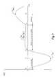
- FIG. 8is a graph illustrating the operation of the series hybrid electric vehicle to produce zero emissions for designated areas
- FIG. 9is a diagram of a route used by the series hybrid electric vehicle with an area where zero emissions are tolerated.
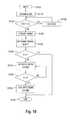
- FIG. 10is a flowchart illustrating an exemplary control of the series hybrid electric vehicle before entering a zero emission zone
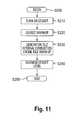
- FIG. 11is a flowchart illustrating an exemplary control of the series hybrid electric vehicle after leaving the zero emission zone.
- an exemplary embodiment of a series type hybrid electric vehicle 10includes a plurality of wheels 11 , 12 , 13 , and 14 and a vehicle chassis 15 .
- the wheels 13 and 14are coupled to electric motors 50 and 60 , respectively, through gear boxes 52 and 62 , respectively.
- the wheels 13 and 14are independently mounted to respective suspension components, such as swing arms.
- the wheels 13 and 14are not coupled together by an axle.
- the wheels 13 and 14may be coupled together, for example, by an axle.
- the wheels 13 and 14may be either the front wheels or the rear wheels of the vehicle 10 .
- the wheels 11 and 12are not driven and may be coupled together by an axle.
- the wheels 11 and 12may also be driven.
- the vehicle 10is a bus having an occupancy capacity in excess of 100 .
- the vehiclemay be a bus of a smaller capacity or that the vehicle may be a smaller passenger vehicle, such as a sedan.
- the vehiclemay be any size and form currently used or later developed.
- the electric motors 50 and 60are powered by a battery array 30 and are controlled by motor controllers 51 and 61 , respectively.
- the electric motors 50 and 60are synchronous, permanent magnet DC brushless motors.
- Each electric motor 50 and 60is rated for 220 Hp and 0-11,000 rpm.
- the maximum combined power output of the electric motors 50 and 60is thus 440 Hp.
- the permanent magnet DC brushless motorsinclude permanent magnets, such as rare earth magnets, for providing a magnetic field as opposed to AC induction motors which create or induce a magnetic field on the rotating portion of the motor.
- the DC brushless motorsare thus inherently more efficient than AC induction motors as no losses occur from inducing the magnetic field.
- the DC brushless motorsalso have a more useful torque profile, a smaller form factor, and lower weight than AC induction motors.
- the DC brushless motorsalso require less energy input for an equivalent power output than AC induction motors.
- this inventionis not limited to permanent magnet DC brushless motors, and other types of electric motors, such as AC induction motors, can be used.
- the series type hybrid electric vehicle 10also includes a generator set (genset) 300 , 310 including an internal combustion engine 300 and a generator 310 that is driven by the internal combustion engine 300 .
- the internal combustion engine 300may be powered by gasoline, diesel, or compressed natural gas. It should be appreciated, however, that the internal combustion engine 300 may be replaced by a fuel cell, turbine or any other number of alternatives for creating usable electric power.
- the internal combustion engine 300may be a 2.5 liter Ford LRG-425 engine powered by compressed natural gas.
- the engine 300is operated to produce 70 Hp. It should be appreciated that the power of the engine 300 may be increased by increasing the RPM of the engine 300 and decreased by decreasing the RPM of the engine 300 .
- the performance enhancement factor of the vehicle 10is 440/70, or at least 6.2.
- Other internal combustion enginescan of course be utilized.
- the generator 310is a DC brushless generator that produces, for example, 240-400 V AC .
- the generatoris operated to produce 345 V AC during certain drive modes.
- An output shaft of the internal combustion engine 300is connected to the generator 310 and the AC voltage of the generator 310 is converted to a DC voltage by a generator controller 320 .
- the converted DC voltagecharges the battery array 30 .
- the battery arraymay include, for example, 26 deep cycle, lead-acid batteries of 12 volts each connected in series. It should be appreciated, however, that other batteries, such as nickel cadmium, metal hydride or lithium ion, may be used and that any number of batteries can be employed, as space permits.
- the battery array voltageranges between 240 and 400 V DC .
- An electronic control unit (ECU) 200includes a programmable logic controller (PLC) 210 and a master control panel (MCP) 220 .
- the MCP 220receives input from various sensors and provides the connection to outputs in the vehicle 10 regarding the information received from the sensors. Some or all of the information is provided to the PLC 210 .
- the PLC 210executes various programs to control, for example, the internal combustion engine 300 , the generator 310 , the generator controller 320 , the electric motors 50 and 60 , and the motor controllers 51 and 61 , based in part on information received from the MCP 220 .
- the vehicle 10includes a cooling system or cooling systems for the internal combustion engine 300 , the generator controller 320 , the battery array 30 , and the motor controllers 51 and 61 .
- the cooling systemmay be a single system which includes a coolant reservoir, a pump for pumping the coolant through a heat exchanger such as a radiator and a fan for moving air across the heat exchanger or a plurality of cooling systems similarly constructed.
- the ECU 200controls the cooling systems, including the pumps and the fans, to perform a heat shedding operation in which the heat generated by the engine 300 , the controllers 320 , 51 , and 61 , the battery array 30 , and various other systems is released to the atmosphere. Any acceptable means and methods for cooling the vehicle components may be utilized.
- the coils of the generator 310are connected to the generator controller 320 .
- the generator controller 320includes two switching insulated or isolated gate bipolar transistors (IGBT) 330 per phase of the generator 310 and their corresponding diodes.
- the generator controllerincludes 6 IGBT 330 .
- the PLC 210controls each IGBT 330 of the generator controller 320 to control the conversion of the AC voltage of the generator 310 to the DC voltage for charging the battery array 30 .
- the PLC 210may switch the IGBT 330 off when the SOC of the battery array 30 reaches an upper control limit to stop the conversion of the AC voltage to DC voltage and prevent overcharging of the battery array 30 .
- the engine 300runs continuously during operation of the vehicle 10 and continuously turns the shaft of the generator 310 .
- the PLC 210switches each IGBT 330 on and off via high speed pulse width modulation (PWM) to control charging of the battery array 30 .
- PWMpulse width modulation
- the PLC 210may control the engine 300 by turning the engine 300 on and off to control charging of the battery array 30 .
- a control circuit for the electric motors 50 and 60includes the motor controllers 51 and 61 .
- the motor controllers 51 and 61receive power from the battery array 30 and distribute the power to the electric motors 50 and 60 by switches B 1 -B 6 of pulse width modulation (PWM) inverters 54 and 64 .
- PWMpulse width modulation
- the PWM inverters 54 and 64generate AC current from the DC battery array 30 .
- the battery current I Bis distributed by the switches B 1 -B 6 , for example IGBT, of the PWM inverters 54 and 64 into motor currents I 1 , I 2 , and I 3 for driving the motors 50 and 60 .
- the motor controllers 51 and 61distribute the battery current I B via the switches B 1 -B 6 by factoring feedback from position sensors 53 and 63 and encoders 56 and 66 that determine the timing or pulsing of electromagnets of the motors 50 and 60 .
- the pole position sensors 53 and 63determine the pole positions of the permanent magnets of the motors 50 and 60 and the encoders 56 and 66 determine the phase angle. It should be appreciated that each pair of pole position sensors 53 and 63 and encoders 56 and 66 , respectively, may be replaced by a phase position sensor and the phase change frequency may be read to determine the speed of rotation of the electric motors 50 and 60 .
- the motor controllers 51 and 61calculate the motor connector voltages U 12 , U 31 , and U 23 based on the rotary velocity and the known flux value of the motors 50 and 60 between the motor connectors.
- the operating point of the inverters 54 and 64is then determined by the rectified voltages of the diodes of the switches B 1 -B 6 or by the voltage Ui of an intermediate circuit including a capacitor C. If the voltage Ui becomes larger than the battery voltage U B , uncontrolled current may flow to the battery array 30 .
- Voltage sensors 55 and 65determine the voltage Ui and the motor controllers 51 and 61 compare the voltage Ui to the battery voltage U B .
- the motor controllers 51 and 61activate the switches B 1 -B 6 to cause magnetizing current to flow to the motors 50 and 60 to avoid unnecessary recharging of the battery array 30 .
- each motor controller 51 and 61receives control data from the ECU 200 through a controller area network (CAN).
- CANcontroller area network
- the ECU 200can communicate with the various sensors and the motor controllers 51 and 61 by, for example, DeviceNetTM, an open, global industry standard communication network.
- each motor controller 51 and 61includes a control unit 101 which includes a field axis current and tongue axis current detector 102 , a field axis current and torque axis current control unit 103 , a field axis current reference control unit 104 , a torque axis current reference control unit 105 , an rpm calculator 106 , a 2/3 phase changer 107 , a phase calculator 108 and a PWM control unit 109 .
- a control unit 101which includes a field axis current and tongue axis current detector 102 , a field axis current and torque axis current control unit 103 , a field axis current reference control unit 104 , a torque axis current reference control unit 105 , an rpm calculator 106 , a 2/3 phase changer 107 , a phase calculator 108 and a PWM control unit 109 .
- the detector 102calculates the torque axis current I t and the field axis current I f by executing a 3-phase, 2-phase coordinate transfer from the input of (1) current detectors 57 and 67 that measure the 3-phase AC current of the motors 50 and 60 and (2) phase calculator 108 that receives input from the position sensors 53 and 63 and the encoders 56 and 66 .
- the field axis current I fis a measure of the current used for winding the motor
- the torque axis current I tis a measure of the back electric current in maintaining the synchronized rotation of the motors 50 and 60 when the rotation of the motors 50 and 60 is reduced.
- the output of detector 102goes to the field axis current and torque axis current control unit 103 .
- the current control unit 103receives (1) a field axis current reference value I fref from the field axis current reference control unit 104 and (2) a torque axis current reference value I tref from the torque axis current reference control unit 105 .
- the reference control units 104 and 105determine the current reference values I fref and I tref by comparing a torque reference value T ref (which is determined by the position of an accelerator pedal of the vehicle) with the actual rotational velocity determined by the rpm calculator 106 that receives input from the encoders 56 and 66 .
- the 2/3 phase changer 107receives input from the current control unit 103 and the phase calculator 108 , and calculates the 3-phase AC reference values by performing a 2-phase/3-phase coordinate transformation.
- the PWM control unit 109generates a PWM signal by comparing the 3-phase reference values received from the 2/3 phase changer 107 with a triangular wave signal.
- the PWM control unit 109communicates this PWM signal to the PWM inverters 54 and 64 .
- a master control switch 20positioned, for example, in an operator area of the vehicle 10 , includes an off position, a drive enable position and an engine run position. Any acceptable switch mechanism can be employed.
- the rotary switch 20 in FIG. 5is merely an example of an acceptable switch.
- the position of the switch 20is input to the MCP 220 .
- the PLC 210controls the electric motors 50 and 60 to run the vehicle in a driver selected zero emissions mode by drawing power from the battery array 30 .
- the engine 300is not operated during the zero emissions mode.
- the range of the vehicle 10 in zero emissions modeis limited as the state of charge (SOC), i.e., the amount of energy stored within a battery, of the battery array 30 will eventually be lowered below a level sufficient to drive the electric motors 50 and 60 to propel the vehicle.
- SOCstate of charge
- the ECU 200instructs the generator 310 to operate as a motor for starting the engine 300 .
- the generator 310receives current from the battery array 30 .
- the currentis supplied until the engine 300 reaches a predetermined idling speed and then the current supply is stopped.
- the engine 300then drives the generator 310 to charge the battery array 30 , as necessary.
- the ECU 200controls the engine 300 by monitoring the engine speed (rpm) as sensed by a tachometer (not shown) and the fuel mixture as sensed by an oxygen sensor (not shown).
- the ECU 200may, for example, control a fuel injection amount of the engine 300 and/or the position of a throttle valve of the engine 300 .
- the ECU 200may also monitor engine conditions such as the oil pressure and the coolant temperature as detected by sensors (not shown).
- An automatic zero emission modeis provided by the ECU 200 while in the engine run position when the SOC of the battery array 30 is sufficient or when the sensors of the vehicle 10 sense areas and routes where zero emission modes are required.
- a control panel 25positioned, for example, in the operator area of the vehicle 10 , includes a plurality of switches 26 - 29 . After starting the vehicle 10 by moving the master switch 20 to the engine run position, one of the switches 26 - 29 is selected to establish a driving mode of the vehicle 10 .
- a first driving mode F1is established by selecting switch 26 .
- the first driving mode F1is established for driving the vehicle at lower speeds under conditions in which the vehicle 10 will start and stop frequently.
- a second driving mode F2is established by selecting switch 27 .
- the second driving mode F2is established for driving the vehicle at higher speeds and under conditions in which the vehicle is started and stopped less frequently.
- the ECU 200controls the electric motors 50 and 60 depending on which driving mode is established.
- the maximum power output and rpm of the electric motors 50 and 60 in the second driving mode F2are higher than the maximum power output and rpm of the motors 50 and 60 in the first driving mode F1.
- the control panel 25also includes a switch 28 to establish a neutral mode N.
- the neutral mode Nthe electric motors 50 and 60 are disengaged by the ECU 200 .
- a reverse mode Ris established by selecting a switch 29 . In the reverse mode R, the electric motors 50 and 60 are controlled to rotate in the opposite direction of the first and second driving modes F1 and F2.
- Poweris consumed from the battery array 30 by the electric motors 50 and 60 during acceleration of the vehicle 10 to a cruising speed. As shown in FIG. 7, the vehicle 10 reaches cruising speed at time t 1 which corresponds to a peak power P peak of the electric motors 50 and 60 .
- the peak power P peak the electric motors 50 and 60is dependent on the driving mode of the vehicle 10 selected by the operator. In the exemplary embodiment of the invention in which the electric motors 50 and 60 are each 220 Hp, the peak power P peak consumed by the electric motors 50 and 60 is 440 Hp.
- the power consumption (traction effort) of the electric motors 50 and 60 during accelerationis represented by the curve below the horizontal axis and the area defined by the curve below the horizontal axis between the times t 0 and t 2 represents the total power consumption of the vehicle 10 during acceleration.
- the ECU 200controls the motor controllers 51 and 61 to limit the peak power P peak the electric motors 50 and 60 may draw from the battery array 30 .
- the traction effort of the electric motors 50 and 60may be reduced between the time t 1 and a time t 2 , and the power consumption by the electric motors 50 and 60 may also be reduced.
- the cruising speed of the vehicle 10is maintained between the time t 2 and a time t 3 .
- the genset 300 , 310is operated to produce power P gen higher than the power consumption (traction effort) of the electric motors 50 and 60 necessary to maintain the vehicle's crusing speed.
- the differential in power between the traction effort and the power generated P genis stored in the battery array 30 .
- the power P gen generated by the genset 300 , 310is dependent on the rpm of the engine 300 and a user demand signal sent to the genset 300 , 310 that is controlled by the ECU 200 .
- the ECU 200controls the engine 300 to generally maintain the rpm of the engine 300 , and the power generated P gen , constant. However, it should be appreciated that the ECU 200 may control the engine 300 to reduce or increase the rpm of the engine 300 , and thus the reduce or increase, respectively, the power generated P gen .
- the power generated P gen by the genset 300 , 310may be reduced if the SOC of the battery array 30 approaches an upper control limit at which the battery array 30 may become overcharged.
- the power generated P gen by the genset 300 , 310may be increased if the SOC of the battery array 30 approaches a lower control limit at which the battery array 30 would be unable to drive the electric motors 50 and 60 with enough torque to propel the vehicle 10 .
- the power generated P genis 70 Hp.
- Regenerative brakingoccurs between the times t 3 and t 4 when the vehicle 10 decelerates after release of the accelerator pedal and/or when the vehicle 10 travels on a downhill slope at a constant speed.
- the electric motors 50 and 60function as generators and current is supplied to the battery array 30 by the electric motors 50 and 60 .
- the power generated P braking during regenerative brakingis stored in the battery array 30 .
- the power generated by the genset 300 , 310 during maintenance of the cruising speed and the power generated by regenerative braking P brakingis represented by the curve above the horizontal axis and the area defined by the curve above the horizontal axis represents the total energy creation and storage of the vehicle 10 during maintenance of the cruising speed and regenerative braking.
- the power P gen of the genset 300 , 310 and the regenerative braking power P brakingare controlled by the ECU 200 to substantially equal the energy consumption (traction effort) of the electric motors 50 and 60 during acceleration.
- the area defined by the curve below the horizontal axisis equal to the area defined by the curve above the horizontal axis.
- the ECU 200controls the traction effort of the electric motors 50 and 60 (including the peak power P peak and the power generated P gen so that the power generated and the power stored do not exceed the power consumed, and vice versa, so as to maintain the SOC of the battery array 30 within a range of control limits.
- the ECU 200controls the power generated P gen and the traction effort of the electric motors 50 and 60 so that the ampere hours during energy consumption do not exceed the thermal capacity of the battery array during power creation and storage.
- the genset 300 , 310operates to produce power higher than the power consumption of the electric motors 50 and 60 .
- the power output by the genset 300 , 310declines as the SOC of the battery array 30 approach a higher level SOC.
- the battery array 30is not fully charged, but managed to a SOC level predetermined to maximize the battery life and to accommodate the required cycle.
- the battery array 30can be maintained at any SOC level less than the maximum SOC level. By keeping the battery array 30 at less than the maximum SOC, the battery array 30 is less likely to experience thermal runaway due to overcharging.
- zero emission operationrefers to the operation of the vehicle 10 when there is substantially no atmospheric, noise, thermal, or other discharges.
- the zero emission operationis automatically executed at predetermined areas or routes during the operation of the vehicle 10 , or selectively activated by the operator.
- One type of environment in which the vehicle 10(which is capable of functioning in a zero emission mode) may be operated is in a closed route or circuit such as an airport or a confined shopping area where the vehicle travels the same circuit continuously.
- a closed route or circuitsuch as an airport or a confined shopping area where the vehicle travels the same circuit continuously.
- the vehiclemay emit zero emissions when it is in or immediately adjacent a terminal, a rental car facility, a parking garage, etc., i.e. any time the vehicle is in or adjacent a facility with limited air flow or circulation.
- These zero emission environmentsmay not be limited to buildings. It may be desirable for the vehicle 10 to operate at zero emissions even when the vehicle is in an open-air environment if public health is a concern, for example, next to a hospital or other medical facility, in an area where vehicle emissions are of a great concern, etc.
- Vehicle 10may, of course, be operated in any environment, and its course may vary, i.e., the vehicle may be operated over open roads, without being restricted to a particular circuit or route.
- vehicle 10in a “closed” route or circuit will be discussed, with the route or circuit having a portion which requires zero emissions.
- the vehicle 10when the vehicle 10 is in the zero emissions mode, little or no exhaust gases, noise, thermal energy or other discharges occur. However, in other exemplary embodiments, certain discharges may occur, while other discharges are restricted. For example, in some exemplary embodiments, little or no exhaust gases or noise may be emitted in the zero emissions mode, but thermal emissions may not be controlled. Any other combinations are possible, and are covered by this invention.
- the vehicle 10moves along a closed vehicle route 450 as indicated by arrow 452 .
- the vehicle route 450includes a zero emission zone 440 .
- the zero emission zone 440may be, but is not limited to, the inside of a building or a tunnel.
- route 450may have more than one zero emission zone.
- FIG. 8is a graph illustrating the power generated by the genet 300 , 310 as the vehicle 10 traverses the circuit 450 .
- the x-axisdefines the zones of operation for the vehicle 10 as it traverses the circuit 450 .
- the y-axisdefines the power generated by the genset 300 , 310 .
- the vehicle 10During normal operation, i.e., when the vehicle 10 is not in the zero emission mode, the vehicle 10 operates as indicated at area 400 of FIG. 8 . In this area 400 , the vehicle 10 operates as discussed above with regard to FIG. 7 .
- the transition zone 430is the area along the route 450 for the vehicle 10 to obtain a sufficient SOC for the battery array so that the vehicle 10 can pass through the zero emission zone 440 without receiving P gen from the genset 300 , 310 , and for removing lingering emissions from the vehicle 10 .
- the transition zone 430may be a variable length along the route 450 .
- This lengthvaries according to the operating speed of the vehicle 10 , the normal SOC of the battery array 30 , the thermal emissions of the vehicle, or any other factor that would effect the transition period for turning off the genset 300 , 310 to prevent emissions from entering the zero emission zone 440 , while maintaining sufficient power to operate the vehicle 10 through the zero emission zone 440 .
- the length of the transition zone 430may also vary according to the safety factors used to ensure that an adequate transition period is provided, i.e., so that there are little or no emissions in the zero emission zone.
- the start of the transition zone 430can be automatically detected by a GPS, radio, mechanical trip, mileage counter, etc. mounted on the bus. It should be appreciated that any automatic means currently available or later developed can be used for the vehicle 10 to determine the start of the transition zone 430 . Also, a visible (e.g., a sign) or an audible signal mechanism could signal to the driver to place the vehicle 10 in the zero emissions zone.
- FIG. 10An exemplary embodiment of a method for controlling the vehicle 10 in the transition zone 430 is shown in FIG. 10 .
- the control methodbegins at step S 100 when the transition zone signal is received by the vehicle 10 or the driver switches the operation to the zero emissions mode.
- the methodthen proceeds to step S 110 where the SOC of the battery array 30 is determined.
- the SOC of the battery array 30is determined by the input from sensors to the MCP 220 .
- the control methodthen proceeds to step S 120 where the SOC of the battery array 30 is compared to an upper control limit UCL.
- the upper control limit UCLis a predetermined electrical charge required for the battery array 30 to operate the electric motors 50 , 60 through the zero emission zone 440 without receiving P gen by the genset 300 , 310 .
- the predetermined electrical chargecan vary according to the length of the zero emission zone 440 , the number of times the vehicle 10 stops/starts, the weight of the vehicle, or any other factor that would reduce the SOC of the battery array 30 while passing through the zero emission zone 440 .
- the predetermined electrical chargecan also vary according to safety factors used to ensure that enough electrical charge is available within the battery array 30 .
- the control methodproceeds to step S 130 and the SOC of the battery array 30 is increased.
- the SOC of the battery array 30can be increased by increasing the P gen by the genset 300 , 310 —by either increasing the P gen of the generator 310 to the current rpm of the engine 300 , which determines the power generated by the genset 300 , 310 , or by increasing the rotational speed of the engine 300 .
- the SOC of the battery array 30can also be increased by modifying the traction drive power profile of the electric motors 50 and 60 to decrease the peak power P peak , or by performing a global power shed by reducing or turning off ancillary systems of the vehicle 10 such as lighting and heating.
- Other methods for increasing the SOC of the battery array 30 above the upper control limit UCLare set forth in co-pending U.S. patent application Ser. No. 09/663,118, which is incorporated by reference.
- the control methodproceeds to step S 140 where the PLC 210 switches off the genset 300 , 310 .
- the battery array 30has a sufficient charge to operate the electric motors 50 , 60 through the zero emission zone 440 without receiving P gen from the genset 300 , 310 .
- step S 150the MCP 220 receives input from various sensors as to the temperature H of the internal combustion engine 300 , generator 310 , generator controller 320 , battery array 30 , and motor controllers 51 , 61 .
- step S 160the temperature H of various components of vehicle 10 , as determined by various sensors, is compared to a predetermined temperature H 1 .
- the temperature H 1is approximately the same as the temperature within the zero emission zone 440 .
- the temperature Hshould be equal to or lower than the temperature H 1 while the vehicle 10 is in the zero emission zone 440 .
- step S 160the control method proceeds to step S 170 and the cooling systems are activated to lower the temperature H to below than or equal to the temperature H 1 .
- the cooling systemsoperate to lower the temperature H to below than or equal to the temperature H 1 at a faster rate at the beginning of the cooling operation than at the end of the cooling operation. In this exemplary embodiment, it is thus possible to increase the safety factor in preventing thermal emissions from entering the zero emission zone 440 as thermal emissions are prevented at a farther distance from the zero emission zone 440 .
- the temperature His again compared to the temperature H 1 in step S 180 . If the temperature H of any of the internal combustion engine 300 , generator 310 , generator controller 320 , battery array 30 , or motor controllers 51 , 61 is again greater than the temperature H 1 (S 180 : No), the control method returns to step S 170 where the cooling systems remain activated.
- step S 190the cooling systems are turned off.
- the control methodthen ends at step S 200 and thus ends the transition zone 430 .
- a dwell period 402is provided before the vehicle 10 enters the zero emission zone 440 .
- the dwell period 402can be a predetermined distance along the route 450 which ensures that the emissions have substantially ceased and that any lingering emissions pass from the vehicle 10 before the vehicle enters the zero emission zone 440 .
- the dwell period 402varies in accordance with the desired safety factor, and may be omitted in certain circumstances.
- the vehicle 10then moves into the zero emission zone 440 , after performing the control method of FIG. 10, as described above.
- the vehicle 10operates in the zero emission mode as the vehicle 10 moves through the zero emission zone 440 . Accordingly, the genset 300 , 310 and the cooling systems are turned off.
- the vehicle 10is only driven by the electric motors 50 , 60 , which are operated by the battery array 30 without receiving P gen by the genset 300 , 310 .
- the vehicle 10then exits the zero emission zone 440 . Similar to detecting the start of the transition zone 430 described above, the start of the transition zone 432 , and thus the end of the zero emission zone 440 , can be automatically detected by a GPS, radio, mechanical trip, mileage counter etc., on the vehicle 10 . In the alternative, a visible or audible signal may be provided for the driver, to advise the driver to manually switch the vehicle 10 back to the normal operating mode.
- the transition zone 432is the transition period for turning on the genset 300 , 310 .
- the transition zone 432may be a variable length along the route 450 . This length varies according to the operating speed of the vehicle 10 , time needed to restart the genset 300 , 310 , or any other factor that would delay the genset 300 , 310 from returning to its normal operation.
- a dwell period 404occurs immediately after the vehicle 10 leaves the zero emission zone 440 .
- the dwell periodcan be provided to ensure that the emissions of the vehicle 10 are substantially prevented from entering the zero emission zone 440 after the vehicle 10 leaves the zero emission zone 440 .
- This dwell period 404may vary in accordance with the safety factor deemed necessary to prevent emissions from entering the zero emission zone 440 , and may be omitted in certain circumstances.
- FIG. 11An exemplary embodiment of a method for controlling the vehicle 10 in the transition zone 432 is shown in FIG. 11 .
- the control methodbegins at step S 200 and proceeds to step S 210 where the PLC 210 restarts the genset 300 , 310 .
- step S 220the control method proceeds to step S 220 where the genset 300 , 310 enters an idle-warm up phase, wherein the engine 300 and generator 310 run at an idle speed, because the genset 300 , 310 has been cooled while passing through the zero emission zone 440 .
- the idle-warm up phasethermally warms the genset 300 , 310 for full output.
- the control methodthen proceeds to step S 230 as the generator 310 reaches an appropriate thermal level to sustain full output.
- the MCP 220receives input from a sensor associated with the generator 310 to determine if the generator 310 has reached an appropriate thermal level.
- the PLC 210stops the idle-warm up phase for the generator 310 and the generator remains idle until the MCP 220 receives input from a sensor associated with the internal combustion engine 300 to indicate that the internal combustion engine has reached an appropriate thermal level to sustain full output.
- step S 230can be removed as the PLC 210 can increase the rate to thermally warm the internal combustion engine 300 in step S 220 , as determined by the MCP 220 based on data from sensors, so that both the internal combustion engine 300 and generator 310 reach the appropriate thermal level at substantially the same time.
- step S 230can be removed as the PLC 210 can increase the rate to thermally warm the generator 310 can be lowered, as determined by the MCP 220 based on data from sensors, in step S 220 so that both the internal combustion engine 300 and generator 310 reach the appropriate thermal level at substantially the same time.
- step S 240the PLC 210 directs the genset 300 , 310 to operate at the maximum, or near maximum capacity, to electrically replenish the SOC of the battery array 30 .
- the control methodthen ends at step S 250 and thus ends the transition zone 432 .
- the vehicleAfter the end of the transition zone 432 , the vehicle thus returns to the normal operation along the route 450 as indicated at area 400 .
- this inventioncovers apparatus and methods to reduce any or more of the various emissions emitted by a vehicle, e.g., exhaust gases, noise, thermal energy, etc. Moreover, this invention covers circumstances in which the emissions are selectively reduced at particular times, even if not reduced to zero, for example where vehicle emissions are reduced for a set period of time, but not completely eliminated. Also, as stated, the subject apparatus and method can be utilized by manual activation, as opposed to the use of automatic switch mechanisms.
Landscapes
- Engineering & Computer Science (AREA)
- Chemical & Material Sciences (AREA)
- Combustion & Propulsion (AREA)
- Transportation (AREA)
- Mechanical Engineering (AREA)
- Automation & Control Theory (AREA)
- Life Sciences & Earth Sciences (AREA)
- Sustainable Development (AREA)
- Sustainable Energy (AREA)
- Power Engineering (AREA)
- Electric Propulsion And Braking For Vehicles (AREA)
- Hybrid Electric Vehicles (AREA)
Abstract
Description
Claims (56)
Priority Applications (3)
| Application Number | Priority Date | Filing Date | Title |
|---|---|---|---|
| US09/764,357US6483198B2 (en) | 2001-01-19 | 2001-01-19 | Hybrid electric vehicle having a selective zero emission mode, and method of selectively operating the zero emission mode |
| EP01310859AEP1225074A3 (en) | 2001-01-19 | 2001-12-22 | A hybrid electric vehicle having a selective zero emission mode, and method of selectively operating the zero emission mode |
| HK03100372.5AHK1048288A1 (en) | 2001-01-19 | 2003-01-15 | A hybrid electric vehicle having a selective zero emission mode, and method of selectively operating the zero emission mode |
Applications Claiming Priority (1)
| Application Number | Priority Date | Filing Date | Title |
|---|---|---|---|
| US09/764,357US6483198B2 (en) | 2001-01-19 | 2001-01-19 | Hybrid electric vehicle having a selective zero emission mode, and method of selectively operating the zero emission mode |
Publications (2)
| Publication Number | Publication Date |
|---|---|
| US20020096886A1 US20020096886A1 (en) | 2002-07-25 |
| US6483198B2true US6483198B2 (en) | 2002-11-19 |
Family
ID=25070490
Family Applications (1)
| Application Number | Title | Priority Date | Filing Date |
|---|---|---|---|
| US09/764,357Expired - LifetimeUS6483198B2 (en) | 2001-01-19 | 2001-01-19 | Hybrid electric vehicle having a selective zero emission mode, and method of selectively operating the zero emission mode |
Country Status (3)
| Country | Link |
|---|---|
| US (1) | US6483198B2 (en) |
| EP (1) | EP1225074A3 (en) |
| HK (1) | HK1048288A1 (en) |
Cited By (61)
| Publication number | Priority date | Publication date | Assignee | Title |
|---|---|---|---|---|
| US6603289B2 (en)* | 2000-11-02 | 2003-08-05 | Denso Corporation | Vehicle alternator control device and method |
| US6625539B1 (en)* | 2002-10-22 | 2003-09-23 | Electricab Taxi Company | Range prediction in fleet management of electric and fuel-cell vehicles |
| US20040021448A1 (en)* | 2000-09-20 | 2004-02-05 | Roland Bluemel | Method for regulating the generator voltage in a motor vehicle |
| US20040026142A1 (en)* | 2001-01-19 | 2004-02-12 | Transportation Techniques, Llc | Method and apparatus for selective operation of a hybrid electric vehicle powerplant |
| US20040174125A1 (en)* | 2000-12-27 | 2004-09-09 | Transportation Techniques Llc | Method and apparatus for adaptive control of hybrid electric vehicle components |
| US20040207348A1 (en)* | 2000-12-27 | 2004-10-21 | Transportation Techniques Llc | Method and apparatus for adaptive control of traction drive units in a hybrid vehicle |
| US20040210356A1 (en)* | 2000-12-27 | 2004-10-21 | Transportation Techniques, Llc | Method and apparatus for selective operation of a hybrid electric vehicle in various driving modes |
| US20040227480A1 (en)* | 2002-11-20 | 2004-11-18 | Honda Motor Co., Ltd. | Control apparatus for controlling regenerative operation of vehicle motor |
| US20040245947A1 (en)* | 2000-12-27 | 2004-12-09 | Transportation Techniques, Llc | Method and apparatus for adaptive control and protection of hybrid electric vehicle systems |
| US20040263099A1 (en)* | 2002-07-31 | 2004-12-30 | Maslov Boris A | Electric propulsion system |
| US20050052080A1 (en)* | 2002-07-31 | 2005-03-10 | Maslov Boris A. | Adaptive electric car |
| US20050146305A1 (en)* | 2002-04-10 | 2005-07-07 | Klaus Kneller | Converter system, method, and converter |
| US6965216B2 (en)* | 2001-11-20 | 2005-11-15 | Edison Source | Method and apparatus for ameliorating electrolyte stratification during rapid charging |
| US20060001319A1 (en)* | 2004-05-27 | 2006-01-05 | Ahmad Raed H | Auxiliary bus system |
| US20060019748A1 (en)* | 2004-07-21 | 2006-01-26 | Aruze Corp. | Communication unit and sales management method of a gaming machine using the communication unit |
| US20060116797A1 (en)* | 2004-12-01 | 2006-06-01 | Moran Brian D | Method of controlling engine stop-start operation for heavy-duty hybrid-electric and hybrid-hydraulic vehicles |
| US20060156916A1 (en)* | 2005-01-18 | 2006-07-20 | Nartron Corporation | Electronic Control for a Hydraulically Driven Generator |
| US20060225930A1 (en)* | 2005-04-07 | 2006-10-12 | Schulte Juergen J | Dual axle electric motor drive and method of use |
| US20070124037A1 (en)* | 2004-12-01 | 2007-05-31 | Moran Brian D | Method of controlling engine stop-start operation for heavy-duty hybrid-electric and hybrid-hydraulic vehicles |
| US20070235236A1 (en)* | 2006-03-31 | 2007-10-11 | Caterpillar Inc. | Power system |
| US20080234096A1 (en)* | 2004-09-30 | 2008-09-25 | Mtd Products Inc | Hybrid Utility Vehicle |
| US20080270016A1 (en)* | 2005-11-21 | 2008-10-30 | Ford Motor Company | Navigation System for a Vehicle |
| WO2009045166A1 (en)* | 2007-10-01 | 2009-04-09 | Singapore Technologies Kinetics Ltd | Radio frequency-based automatic drive switching of hybrid vehicle |
| US20090134848A1 (en)* | 2006-01-17 | 2009-05-28 | Nartron Corporation | Electronic control for a hydraulically driven generator |
| US20090192660A1 (en)* | 2008-01-25 | 2009-07-30 | Ford Motor Company | Method and system for controlling a motive power system of an automotive vehicle |
| US20100097038A1 (en)* | 2006-01-17 | 2010-04-22 | Nartron Corporation | Electronic control for a hydraulically driven generator |
| US20100097040A1 (en)* | 2006-01-17 | 2010-04-22 | Nartron Corporation | Electronic control for a hydraulically driven auxiliary power source |
| US20100108416A1 (en)* | 2008-11-04 | 2010-05-06 | Lind John A | Direct current drive land vehicle |
| US20100156117A1 (en)* | 2008-12-19 | 2010-06-24 | Caterpillar Inc. | Genset power system having multiple modes of operation |
| CN101830219A (en)* | 2009-03-12 | 2010-09-15 | 福特全球技术公司 | Hybrid electric vehicle |
| US20100230193A1 (en)* | 2009-03-12 | 2010-09-16 | Ford Global Technologies, Llc | Plug-in vehicle function indication |
| US20100280887A1 (en)* | 2009-04-30 | 2010-11-04 | Searete Llc, A Limited Liability Corporation Of The State Of Delaware | Awarding privileges to a vehicle based upon one or more fuel utilization characteristics |
| US20100280691A1 (en)* | 2009-04-30 | 2010-11-04 | Searete Llc, A Limited Liability Corporation Of The State Of Delaware | Awarding standings to a vehicle based upon one or more fuel utilization characteristics |
| US20100280705A1 (en)* | 2009-04-30 | 2010-11-04 | Searete Llc, A Limited Liability Corporation Of The State Of Delaware | Awarding standings to a vehicle based upon one or more fuel utilization characteristics |
| US20100280703A1 (en)* | 2009-04-30 | 2010-11-04 | Searete Llc, A Limited Liability Corporation Of The State Of Delaware | Awarding Privileges to a vehicle based upon one or more fuel utilization characteristics |
| US20100280688A1 (en)* | 2009-04-30 | 2010-11-04 | Searete Llc, A Limited Liability Corporation Of The State Of Delaware | Awarding standings to a vehicle based upon one or more fuel utilization characteristics |
| US20100280888A1 (en)* | 2009-04-30 | 2010-11-04 | Searete LLC, a limited libaility corporation of the State of Delaware | Awarding privileges to a vehicle based upon one or more fuel utilization characteristics |
| US20100280708A1 (en)* | 2009-04-30 | 2010-11-04 | Searete Llc, A Limited Liability Corporation Of The State Of Delaware | Awarding standings to a vehicle based upon one or more fuel utilization characteristics |
| US20100280706A1 (en)* | 2009-04-30 | 2010-11-04 | Searete Llc, A Limited Liability Corporation Of State Of Delaware | Awarding standings to a vehicle based upon one or more fuel utilization characteristics |
| US20100280690A1 (en)* | 2009-04-30 | 2010-11-04 | Searete Llc, A Limited Liability Corporation Of The State Of Delaware | Awarding standings to a vehicle based upon one or more fuel utilization characteristics |
| US20100280686A1 (en)* | 2009-04-30 | 2010-11-04 | Searete Llc, A Limited Liability Corporation Of The State Of Delaware | Awarding privileges to a vehicle based upon one or more fuel utilization characteristics |
| US20100280885A1 (en)* | 2009-04-30 | 2010-11-04 | Searete Llc, A Limited Liability Corporation Of The State Of Delaware | Awarding privileges to a vehicle based upon one or more fuel utilization characteristics |
| US20100280692A1 (en)* | 2009-04-30 | 2010-11-04 | Searete Llc, A Limited Liability Corporation Of The State Of Delaware | Awarding standings to a vehicle based upon one or more fuel utilization characteristics |
| US20100280709A1 (en)* | 2009-04-30 | 2010-11-04 | Searete Llc, A Limited Liability Corporation Of The State Of Delaware | Awarding standings to a vehicle based upon one or more fuel utilization characteristics |
| US20100299054A1 (en)* | 2007-11-12 | 2010-11-25 | Renault S.A.S. | Method and system for managing the operation of a motor vehicle as a function of driving conditions |
| US20110106354A1 (en)* | 2009-04-30 | 2011-05-05 | Searete Llc, A Limited Liability Corporation Of The State Of Delaware | Awarding standings to a vehicle based upon one or more fuel utilization characteristics |
| US20110106591A1 (en)* | 2009-04-30 | 2011-05-05 | Searete Llc, A Limited Liability Corporation Of The State Of Delaware | Awarding standings to a vehicle based upon one or more fuel utilization characteristics |
| US20110139882A1 (en)* | 2009-12-15 | 2011-06-16 | Webasto Ag | Fuel-operated heating device and vehicle heating system |
| US20110169273A1 (en)* | 2008-09-26 | 2011-07-14 | Arb Greenpower, Llc | Hybrid energy conversion system |
| DE102011002306A1 (en) | 2011-04-28 | 2012-10-31 | Dr. Ing. H.C. F. Porsche Aktiengesellschaft | Operating method for hybrid vehicle, involves performing switching from charging mode to zero emission mode of hybrid vehicle after renewed actuation of operating device, and driving electric drive unit by battery in zero emission mode |
| US20130168171A1 (en)* | 2012-01-03 | 2013-07-04 | Erik Buell | Ridden vehicle with hybrid power system |
| US8950539B2 (en) | 2012-01-03 | 2015-02-10 | Hero Motorcorp Ltd. | Lightweight integrated rear suspension and drive enclosure for a ridden motorized vehicle |
| US9108503B2 (en) | 2011-06-15 | 2015-08-18 | Ford Global Technologies, Llc | Method to prioritize electric-only vehicle (EV) mode for a vehicle |
| US9315190B2 (en) | 2014-04-30 | 2016-04-19 | Ford Global Technologies, Llc | Hybrid electric vehicle preferred mode |
| US9384515B2 (en) | 2014-05-07 | 2016-07-05 | Ford Global Technologies, Llc | Shared vehicle management |
| US9428173B2 (en) | 2013-10-29 | 2016-08-30 | Toyota Motor Engineering & Manufacturing North America, Inc. | Vehicle battery pre-charge feature |
| US10118604B1 (en) | 2017-07-07 | 2018-11-06 | Toyota Motor Engineering & Manufacturing North America, Inc. | System and method for improved battery pre-charge and deactivation timing in traffic |
| WO2018204451A1 (en)* | 2017-05-04 | 2018-11-08 | Cummins Inc. | Systems and methods for hybrid electric vehicle battery state of charge reference scheduling |
| US20220196420A1 (en)* | 2020-12-23 | 2022-06-23 | Toyota Jidosha Kabushiki Kaisha | Computing device, route display device, and control system, for hybrid vehicle |
| US11835351B2 (en) | 2019-07-18 | 2023-12-05 | Cummins Inc. | Optimal route planning for electric vehicles |
| US12065128B2 (en) | 2021-03-25 | 2024-08-20 | Cummins Inc. | Methods and systems for managing and controlling emissions in a hybrid system |
Families Citing this family (37)
| Publication number | Priority date | Publication date | Assignee | Title |
|---|---|---|---|---|
| JP3969068B2 (en)* | 2001-11-21 | 2007-08-29 | コベルコ建機株式会社 | Actuator drive device for hybrid work machine |
| JP3613236B2 (en)* | 2001-12-03 | 2005-01-26 | コベルコ建機株式会社 | Work machine |
| US7482704B2 (en)* | 2003-09-08 | 2009-01-27 | Cummins Power Generation Inc. | Automatic generator starting protection |
| CN101002101A (en)* | 2004-06-25 | 2007-07-18 | 动态控制有限公司 | An electric vehicle, a display device for an electric vehicle and a method of displaying information |
| US7100362B2 (en)* | 2004-07-30 | 2006-09-05 | Ford Global Technologies, Llc | Vehicle and method for operating a vehicle to reduce exhaust emissions |
| DE102005025251A1 (en)* | 2005-06-02 | 2006-12-14 | Bayerische Motoren Werke Ag | Device for regulating the power output of an electric generator in motor vehicles |
| US7397141B2 (en)* | 2006-01-30 | 2008-07-08 | Deere & Company | Power generator using traction drive electronics of a vehicle |
| DE102006045891B4 (en)* | 2006-09-28 | 2008-10-02 | Continental Automotive Gmbh | Method and device for operating a motor vehicle |
| AT506272B1 (en) | 2009-04-02 | 2015-01-15 | Avl List Gmbh | METHOD FOR OPERATING AN ELECTRIC VEHICLE |
| CN101580014B (en)* | 2009-04-27 | 2011-06-29 | 武汉理工大学 | Electric vehicle motor automatic variable speed drive system |
| WO2011033528A2 (en) | 2009-09-15 | 2011-03-24 | Kpit Cummins Infosystems Limited | Motor assistance for a hybrid vehicle |
| JP5926182B2 (en) | 2009-09-15 | 2016-05-25 | ケーピーアイティ テクノロジーズ リミテッド | Hybrid vehicle motor assistance based on user input |
| KR20120072372A (en) | 2009-09-15 | 2012-07-03 | 케이피아이티 커민즈 인포시스템즈 엘티디. | Motor assistance for a hybrid vehicle based on predicted driving range |
| KR101897836B1 (en) | 2009-09-15 | 2018-09-12 | 케이피아이티 테크놀로지스 엘티디. | Method of converting vehicle into hybrid vehicle |
| AT507916B1 (en) | 2010-04-29 | 2012-01-15 | Avl List Gmbh | METHOD FOR OPERATING AN ELECTRIC VEHICLE |
| AT508065B1 (en) | 2010-06-24 | 2012-09-15 | Avl List Gmbh | METHOD FOR OPERATING AN ELECTRIC VEHICLE |
| DE102011013485A1 (en)* | 2011-03-10 | 2012-09-13 | Audi Ag | Method for operating a range extender in a vehicle with electric drive |
| GB201201255D0 (en)* | 2012-01-25 | 2012-03-07 | Jaguar Cars | Hybrid vehicle controller and method of controlling a hybrid vehicle (moving soc) |
| DE102012011501A1 (en)* | 2012-06-09 | 2013-12-12 | Gm Global Technology Operations, Llc | Motor vehicle i.e. motor car, operating method, involves recognizing road-controlled zone, determining parameters of motor vehicle, and transmitting parameters of motor vehicle to authorization location |
| FR3005296B1 (en)* | 2013-05-03 | 2016-10-07 | Renault Sa | METHOD FOR OPTIMIZING THE ENERGY CONSUMPTION OF A HYBRID VEHICLE |
| DE102014201054A1 (en)* | 2014-01-22 | 2015-07-23 | Robert Bosch Gmbh | Method and device for operating a battery, in particular a lithium ion battery, in a consumer |
| US9738150B2 (en)* | 2014-02-18 | 2017-08-22 | Richard Chi-Hsueh | Energy efficient vehicle and disc-type dynamic motor thereof |
| US9156370B1 (en)* | 2014-05-15 | 2015-10-13 | Honda Motor Co. Ltd. | Offboard power supply system having emission level evaluation for an electric vehicle |
| KR102181294B1 (en)* | 2014-05-27 | 2020-11-20 | 두산인프라코어 주식회사 | Wheel driving system for construction machinery |
| US10118603B2 (en)* | 2015-10-30 | 2018-11-06 | Toyota Motor Engineering & Manufacturing North America, Inc. | Systems and methods for traffic learning |
| US9821790B2 (en)* | 2015-12-17 | 2017-11-21 | Jaguar Land Rover Limited | System and method to facilitate satisfying low emission zone requirements |
| GB2547714B (en)* | 2016-02-29 | 2021-11-17 | Eclectic As | Vehicle emission control |
| US10710443B2 (en)* | 2016-10-18 | 2020-07-14 | Richard Chi-Hsueh | Multi-ring disc motor |
| KR102370923B1 (en)* | 2017-09-26 | 2022-03-07 | 현대자동차주식회사 | Spatial Classification type Stop Control Method and Vehicle thereof |
| US11022451B2 (en)* | 2018-11-01 | 2021-06-01 | Thermo King Corporation | Methods and systems for generation and utilization of supplemental stored energy for use in transport climate control |
| US11394326B2 (en)* | 2018-11-15 | 2022-07-19 | Nissan Motor Co., Ltd. | Control method and control device for electric vehicle |
| KR20210077088A (en)* | 2019-12-16 | 2021-06-25 | 현대자동차주식회사 | Hybrid vehicle and method of controlling engine operation for the same |
| DE102020207952A1 (en) | 2020-06-26 | 2021-12-30 | Dr. Ulrich Knapp GmbH | Method for controlling a power generation device to extend the range |
| DE102020210382A1 (en)* | 2020-08-14 | 2022-02-17 | Continental Teves Ag & Co. Ohg | Method for controlling an electric motor drive of a motor vehicle |
| US11959758B2 (en)* | 2020-10-05 | 2024-04-16 | Ford Global Technologies, Llc | Systems and methods for optimizing vehicle deployment |
| JP7338616B2 (en)* | 2020-12-03 | 2023-09-05 | トヨタ自動車株式会社 | HYBRID VEHICLE CONTROL DEVICE AND HYBRID VEHICLE CONTROL METHOD |
| US12203762B2 (en)* | 2021-07-19 | 2025-01-21 | Ford Global Technologies, Llc | Real-time carbon footprint estimation |
Citations (31)
| Publication number | Priority date | Publication date | Assignee | Title |
|---|---|---|---|---|
| US4187436A (en) | 1977-01-12 | 1980-02-05 | Automobiles Peugeot | Device for regulating the source of electric energy on a hybrid electric vehicle |
| EP0177770A1 (en) | 1984-09-14 | 1986-04-16 | Siemens Aktiengesellschaft | Driving system for electric driven vehicles |
| EP0496059A1 (en) | 1990-11-30 | 1992-07-29 | Digitalia S.R.L. | Method and device for transmission control in electrical feed vehicles |
| US5285862A (en) | 1992-03-16 | 1994-02-15 | Toyota Jidosha Kabushiki Kaisha | Power supply system for hybrid vehicles |
| WO1994007301A1 (en) | 1992-09-24 | 1994-03-31 | Siemens Aktiengesellschaft | Process and device for regulating a converter-powered, permanently excited synchronous motor |
| US5318142A (en) | 1992-11-05 | 1994-06-07 | Ford Motor Company | Hybrid drive system |
| US5345155A (en) | 1991-03-25 | 1994-09-06 | Hitachi, Ltd. | Control system for electric vehicle |
| US5481460A (en)* | 1990-10-03 | 1996-01-02 | Hitachi, Ltd. | Controller for electric vehicle |
| US5512022A (en) | 1993-10-26 | 1996-04-30 | Suzuki; Naruhito | Motor mechanism |
| US5589743A (en) | 1995-03-03 | 1996-12-31 | General Electric Company | Integrated cranking inverter and boost converter for a series hybrid drive system |
| US5629586A (en) | 1994-06-30 | 1997-05-13 | Toshiba Lighting And Technology Corporation | Compact fluorescent lamp unit having first and second sealed end portions separated by a support member |
| US5629596A (en)* | 1991-10-08 | 1997-05-13 | Fuji Electric Co., Ltd. | Method of controlling electric vehicle driven by an internal combustion engine |
| US5642270A (en) | 1991-08-01 | 1997-06-24 | Wavedriver Limited | Battery powered electric vehicle and electrical supply system |
| US5650713A (en)* | 1994-07-01 | 1997-07-22 | Nippondenso Co., Ltd. | Control device for a hybrid automobile |
| DE19722175A1 (en) | 1996-05-29 | 1997-12-04 | Hitachi Ltd | Drive system for electric vehicle |
| WO1998001941A1 (en) | 1996-07-09 | 1998-01-15 | Solaria Research Enterprise, Ltd. | Control system for separately excited dc motor |
| US5726541A (en) | 1992-04-28 | 1998-03-10 | Dynamic Controls Limited | Failure detection and communication system for electrically driven vehicles |
| US5739664A (en) | 1996-02-05 | 1998-04-14 | Ford Global Technologies, Inc. | Induction motor drive controller |
| US5785138A (en)* | 1992-05-15 | 1998-07-28 | Mitsubishi Jidosha Kogyo Kabushiki Kaisha | Operating method for a hybrid car |
| US5786640A (en)* | 1995-02-13 | 1998-07-28 | Nippon Soken, Inc. | Generator control system for a hybrid vehicle driven by an electric motor and an internal combustion engine |
| US5804935A (en) | 1997-02-06 | 1998-09-08 | Radev; Vladimir | Drive system for electric vehicles |
| US5878830A (en) | 1997-02-18 | 1999-03-09 | Meritor Heavy Vehicle Systems, Llc. | Space saving mounting for electrically driven vehicle wheels |
| EP0906847A2 (en) | 1997-10-02 | 1999-04-07 | Siemens Aktiengesellschaft | Drive device for an electric vehicle |
| US5898282A (en)* | 1996-08-02 | 1999-04-27 | B.C. Research Inc. | Control system for a hybrid vehicle |
| US5905349A (en) | 1998-04-23 | 1999-05-18 | Ford Motor Company | Method of controlling electric motor torque in an electric vehicle |
| US5915488A (en) | 1995-01-27 | 1999-06-29 | Fichtel & Sachs Ag | Hybrid non-rail tired vehicle with safety mechanism |
| EP0925988A2 (en) | 1997-12-25 | 1999-06-30 | Nissan Motor Co., Ltd. | Vehicle drive device and vehicle drive device control method |
| US5924504A (en) | 1997-02-18 | 1999-07-20 | Meritor Heavy Vehicle Systems, Llc | Suspension drive unit assembly for an electrically driven vehicle |
| US6073712A (en)* | 1997-01-23 | 2000-06-13 | Chrysler Corporation | Method of power output level control for a hybrid power train system |
| US6242873B1 (en) | 2000-01-31 | 2001-06-05 | Azure Dynamics Inc. | Method and apparatus for adaptive hybrid vehicle control |
| US6314346B1 (en)* | 1998-12-07 | 2001-11-06 | Honda Giken Kogyo Kabushiki Kaisha | Control system for hybrid vehicle |
Family Cites Families (5)
| Publication number | Priority date | Publication date | Assignee | Title |
|---|---|---|---|---|
| IT1246063B (en)* | 1991-04-23 | 1994-11-07 | Iveco Fiat | POWER UNIT FOR A MOTOR VEHICLE EQUIPPED WITH THERMALLY OPERATED MOTOR VEHICLES AND ELECTRICALLY OPERATED MOTOR VEHICLES |
| JP3092403B2 (en)* | 1993-09-06 | 2000-09-25 | 三菱自動車工業株式会社 | Hybrid electric vehicle |
| US6116363A (en)* | 1995-05-31 | 2000-09-12 | Frank Transportation Technology, Llc | Fuel consumption control for charge depletion hybrid electric vehicles |
| US5704440A (en)* | 1995-05-31 | 1998-01-06 | New York Institute Of Technology | Energy distribution method for hydrid electric vehicle |
| US6464026B1 (en)* | 1998-10-09 | 2002-10-15 | John Horsley | Control system for parallel hybrid vehicle |
- 2001
- 2001-01-19USUS09/764,357patent/US6483198B2/ennot_activeExpired - Lifetime
- 2001-12-22EPEP01310859Apatent/EP1225074A3/ennot_activeWithdrawn
- 2003
- 2003-01-15HKHK03100372.5Apatent/HK1048288A1/enunknown
Patent Citations (31)
| Publication number | Priority date | Publication date | Assignee | Title |
|---|---|---|---|---|
| US4187436A (en) | 1977-01-12 | 1980-02-05 | Automobiles Peugeot | Device for regulating the source of electric energy on a hybrid electric vehicle |
| EP0177770A1 (en) | 1984-09-14 | 1986-04-16 | Siemens Aktiengesellschaft | Driving system for electric driven vehicles |
| US5481460A (en)* | 1990-10-03 | 1996-01-02 | Hitachi, Ltd. | Controller for electric vehicle |
| EP0496059A1 (en) | 1990-11-30 | 1992-07-29 | Digitalia S.R.L. | Method and device for transmission control in electrical feed vehicles |
| US5345155A (en) | 1991-03-25 | 1994-09-06 | Hitachi, Ltd. | Control system for electric vehicle |
| US5642270A (en) | 1991-08-01 | 1997-06-24 | Wavedriver Limited | Battery powered electric vehicle and electrical supply system |
| US5629596A (en)* | 1991-10-08 | 1997-05-13 | Fuji Electric Co., Ltd. | Method of controlling electric vehicle driven by an internal combustion engine |
| US5285862A (en) | 1992-03-16 | 1994-02-15 | Toyota Jidosha Kabushiki Kaisha | Power supply system for hybrid vehicles |
| US5726541A (en) | 1992-04-28 | 1998-03-10 | Dynamic Controls Limited | Failure detection and communication system for electrically driven vehicles |
| US5785138A (en)* | 1992-05-15 | 1998-07-28 | Mitsubishi Jidosha Kogyo Kabushiki Kaisha | Operating method for a hybrid car |
| WO1994007301A1 (en) | 1992-09-24 | 1994-03-31 | Siemens Aktiengesellschaft | Process and device for regulating a converter-powered, permanently excited synchronous motor |
| US5318142A (en) | 1992-11-05 | 1994-06-07 | Ford Motor Company | Hybrid drive system |
| US5512022A (en) | 1993-10-26 | 1996-04-30 | Suzuki; Naruhito | Motor mechanism |
| US5629586A (en) | 1994-06-30 | 1997-05-13 | Toshiba Lighting And Technology Corporation | Compact fluorescent lamp unit having first and second sealed end portions separated by a support member |
| US5650713A (en)* | 1994-07-01 | 1997-07-22 | Nippondenso Co., Ltd. | Control device for a hybrid automobile |
| US5915488A (en) | 1995-01-27 | 1999-06-29 | Fichtel & Sachs Ag | Hybrid non-rail tired vehicle with safety mechanism |
| US5786640A (en)* | 1995-02-13 | 1998-07-28 | Nippon Soken, Inc. | Generator control system for a hybrid vehicle driven by an electric motor and an internal combustion engine |
| US5589743A (en) | 1995-03-03 | 1996-12-31 | General Electric Company | Integrated cranking inverter and boost converter for a series hybrid drive system |
| US5739664A (en) | 1996-02-05 | 1998-04-14 | Ford Global Technologies, Inc. | Induction motor drive controller |
| DE19722175A1 (en) | 1996-05-29 | 1997-12-04 | Hitachi Ltd | Drive system for electric vehicle |
| WO1998001941A1 (en) | 1996-07-09 | 1998-01-15 | Solaria Research Enterprise, Ltd. | Control system for separately excited dc motor |
| US5898282A (en)* | 1996-08-02 | 1999-04-27 | B.C. Research Inc. | Control system for a hybrid vehicle |
| US6073712A (en)* | 1997-01-23 | 2000-06-13 | Chrysler Corporation | Method of power output level control for a hybrid power train system |
| US5804935A (en) | 1997-02-06 | 1998-09-08 | Radev; Vladimir | Drive system for electric vehicles |
| US5878830A (en) | 1997-02-18 | 1999-03-09 | Meritor Heavy Vehicle Systems, Llc. | Space saving mounting for electrically driven vehicle wheels |
| US5924504A (en) | 1997-02-18 | 1999-07-20 | Meritor Heavy Vehicle Systems, Llc | Suspension drive unit assembly for an electrically driven vehicle |
| EP0906847A2 (en) | 1997-10-02 | 1999-04-07 | Siemens Aktiengesellschaft | Drive device for an electric vehicle |
| EP0925988A2 (en) | 1997-12-25 | 1999-06-30 | Nissan Motor Co., Ltd. | Vehicle drive device and vehicle drive device control method |
| US5905349A (en) | 1998-04-23 | 1999-05-18 | Ford Motor Company | Method of controlling electric motor torque in an electric vehicle |
| US6314346B1 (en)* | 1998-12-07 | 2001-11-06 | Honda Giken Kogyo Kabushiki Kaisha | Control system for hybrid vehicle |
| US6242873B1 (en) | 2000-01-31 | 2001-06-05 | Azure Dynamics Inc. | Method and apparatus for adaptive hybrid vehicle control |
Non-Patent Citations (1)
| Title |
|---|
| U.S. patent application Ser. No. 09/663,118, filed Sep. 15, 2000. |
Cited By (99)
| Publication number | Priority date | Publication date | Assignee | Title |
|---|---|---|---|---|
| US7091626B2 (en)* | 2000-09-20 | 2006-08-15 | Daimlerchrysler Ag | Method for regulating the generator voltage in a motor vehicle |
| US20040021448A1 (en)* | 2000-09-20 | 2004-02-05 | Roland Bluemel | Method for regulating the generator voltage in a motor vehicle |
| US6603289B2 (en)* | 2000-11-02 | 2003-08-05 | Denso Corporation | Vehicle alternator control device and method |
| US6897629B2 (en) | 2000-12-27 | 2005-05-24 | Transportation Techniques, Llc | Method and apparatus for adaptive control and protection of hybrid electric vehicle systems |
| US20040174125A1 (en)* | 2000-12-27 | 2004-09-09 | Transportation Techniques Llc | Method and apparatus for adaptive control of hybrid electric vehicle components |
| US20040207348A1 (en)* | 2000-12-27 | 2004-10-21 | Transportation Techniques Llc | Method and apparatus for adaptive control of traction drive units in a hybrid vehicle |
| US20040210356A1 (en)* | 2000-12-27 | 2004-10-21 | Transportation Techniques, Llc | Method and apparatus for selective operation of a hybrid electric vehicle in various driving modes |
| US7122979B2 (en) | 2000-12-27 | 2006-10-17 | Transportation Techniques, Llc | Method and apparatus for selective operation of a hybrid electric vehicle in various driving modes |
| US20040245947A1 (en)* | 2000-12-27 | 2004-12-09 | Transportation Techniques, Llc | Method and apparatus for adaptive control and protection of hybrid electric vehicle systems |
| US7071642B2 (en) | 2000-12-27 | 2006-07-04 | Transportation Techniques, Llc | Method and apparatus for adaptive control of traction drive units in a hybrid vehicle |
| US6877576B2 (en)* | 2001-01-19 | 2005-04-12 | Transportation Techniques, Llc. | Method and apparatus for selective operation of a hybrid electric vehicle powerplant |
| US20040026142A1 (en)* | 2001-01-19 | 2004-02-12 | Transportation Techniques, Llc | Method and apparatus for selective operation of a hybrid electric vehicle powerplant |
| US6965216B2 (en)* | 2001-11-20 | 2005-11-15 | Edison Source | Method and apparatus for ameliorating electrolyte stratification during rapid charging |
| US7786694B2 (en)* | 2002-04-10 | 2010-08-31 | Sew-Eurodrive Gmbh & Co. Kg | Converter system, method, and converter |
| US20050146305A1 (en)* | 2002-04-10 | 2005-07-07 | Klaus Kneller | Converter system, method, and converter |
| US20050052080A1 (en)* | 2002-07-31 | 2005-03-10 | Maslov Boris A. | Adaptive electric car |
| US20040263099A1 (en)* | 2002-07-31 | 2004-12-30 | Maslov Boris A | Electric propulsion system |
| US6625539B1 (en)* | 2002-10-22 | 2003-09-23 | Electricab Taxi Company | Range prediction in fleet management of electric and fuel-cell vehicles |
| US20040078141A1 (en)* | 2002-10-22 | 2004-04-22 | Kittell Robert P. | Range prediction in fleet management of electric and fuel-cell vehicles |
| US6826460B2 (en) | 2002-10-22 | 2004-11-30 | Michael M. Schneck | Range prediction in fleet management of electric and fuel-cell vehicles |
| US20040227480A1 (en)* | 2002-11-20 | 2004-11-18 | Honda Motor Co., Ltd. | Control apparatus for controlling regenerative operation of vehicle motor |
| US7034475B2 (en)* | 2002-11-20 | 2006-04-25 | Honda Motor Co., Ltd. | Control apparatus for controlling regenerative operation of vehicle motor |
| US20060001319A1 (en)* | 2004-05-27 | 2006-01-05 | Ahmad Raed H | Auxiliary bus system |
| US20060131888A1 (en)* | 2004-05-27 | 2006-06-22 | Ahmad Raed H | High frequency bus method |
| US7330012B2 (en)* | 2004-05-27 | 2008-02-12 | Siemens Aktiengesellschaft | High frequency bus system |
| US7479757B2 (en) | 2004-05-27 | 2009-01-20 | Siemens Energy & Automation, Inc. | System and method for a cooling system |
| US20060001397A1 (en)* | 2004-05-27 | 2006-01-05 | Ahmad Raed H | High frequency bus system |
| US7227273B2 (en)* | 2004-05-27 | 2007-06-05 | Siemens Energy & Automation, Inc. | High frequency bus method |
| US7385372B2 (en) | 2004-05-27 | 2008-06-10 | Siemens Energy & Automation, Inc. | Auxiliary bus system |
| US20060019748A1 (en)* | 2004-07-21 | 2006-01-26 | Aruze Corp. | Communication unit and sales management method of a gaming machine using the communication unit |
| US20080234096A1 (en)* | 2004-09-30 | 2008-09-25 | Mtd Products Inc | Hybrid Utility Vehicle |
| US7689331B2 (en) | 2004-12-01 | 2010-03-30 | Ise Corporation | Method of controlling engine stop-start operation for heavy-duty hybrid-electric and hybrid-hydraulic vehicles |
| US7657350B2 (en) | 2004-12-01 | 2010-02-02 | Ise Corporation | Method of controlling engine stop-start operation for heavy-duty hybrid-electric and hybrid-hydraulic vehicles |
| US20080097661A1 (en)* | 2004-12-01 | 2008-04-24 | Ise Corporation | Method of controlling engine stop-start operation for heavy-duty hybrid-electric and hybrid-hydraulic vehicles |
| US20080147260A1 (en)* | 2004-12-01 | 2008-06-19 | Ise Corporation | Method of Controlling Engine Stop-Start Operation for Heavy-Duty Hybrid-Electric and Hybrid- Hydraulic Vehicles |
| US20060116797A1 (en)* | 2004-12-01 | 2006-06-01 | Moran Brian D | Method of controlling engine stop-start operation for heavy-duty hybrid-electric and hybrid-hydraulic vehicles |
| US20080177434A1 (en)* | 2004-12-01 | 2008-07-24 | Ise Corporation | Method of Controlling Engine Stop-Start Operation for Heavy-Duty Hybrid-Electric and Hybrid- Hydraulic Vehicles |
| US20070124037A1 (en)* | 2004-12-01 | 2007-05-31 | Moran Brian D | Method of controlling engine stop-start operation for heavy-duty hybrid-electric and hybrid-hydraulic vehicles |
| US7689330B2 (en)* | 2004-12-01 | 2010-03-30 | Ise Corporation | Method of controlling engine stop-start operation for heavy-duty hybrid-electric and hybrid-hydraulic vehicles |
| US7680568B2 (en) | 2004-12-01 | 2010-03-16 | Ise Corporation | Method of controlling engine stop-start operation for heavy-duty hybrid-electric and hybrid-hydraulic vehicles |
| US7657351B2 (en) | 2004-12-01 | 2010-02-02 | Ise Corporation | Method of controlling engine stop-start operation for heavy-duty hybrid-electric and hybrid-hydraulic vehicles |
| US7459800B2 (en)* | 2005-01-18 | 2008-12-02 | Nartron Corporation | Electronic control for a hydraulically driven generator |
| US20060156916A1 (en)* | 2005-01-18 | 2006-07-20 | Nartron Corporation | Electronic Control for a Hydraulically Driven Generator |
| US20060225930A1 (en)* | 2005-04-07 | 2006-10-12 | Schulte Juergen J | Dual axle electric motor drive and method of use |
| US20080270016A1 (en)* | 2005-11-21 | 2008-10-30 | Ford Motor Company | Navigation System for a Vehicle |
| US20100097040A1 (en)* | 2006-01-17 | 2010-04-22 | Nartron Corporation | Electronic control for a hydraulically driven auxiliary power source |
| US20090134848A1 (en)* | 2006-01-17 | 2009-05-28 | Nartron Corporation | Electronic control for a hydraulically driven generator |
| US20100097038A1 (en)* | 2006-01-17 | 2010-04-22 | Nartron Corporation | Electronic control for a hydraulically driven generator |
| US8269360B2 (en) | 2006-01-17 | 2012-09-18 | Uusi, Llc | Electronic control for a hydraulically driven auxiliary power source |
| US7759811B2 (en) | 2006-01-17 | 2010-07-20 | Nartron Corporation | Electronic control for a hydraulically driven generator |
| US8269359B2 (en) | 2006-01-17 | 2012-09-18 | Uusi, Llc | Electronic control for a hydraulically driven generator |
| EP2005320A4 (en)* | 2006-03-28 | 2011-01-05 | Ise Corp | Method of controlling engine stop-start operation for heavy-duty hybrid-electric and hybrid-hydraulic vehicles |
| WO2007112233A3 (en)* | 2006-03-28 | 2008-06-26 | Ise Corp | Method of controlling engine operation in a hybrid vehicle |
| US7543665B2 (en) | 2006-03-31 | 2009-06-09 | Caterpillar Inc. | Power system |
| US20070235236A1 (en)* | 2006-03-31 | 2007-10-11 | Caterpillar Inc. | Power system |
| WO2009045166A1 (en)* | 2007-10-01 | 2009-04-09 | Singapore Technologies Kinetics Ltd | Radio frequency-based automatic drive switching of hybrid vehicle |
| CN101842277A (en)* | 2007-10-01 | 2010-09-22 | 新加坡科技动力有限公司 | The automatic driving to hybrid vehicle based on radio frequency is switched |
| US20100299054A1 (en)* | 2007-11-12 | 2010-11-25 | Renault S.A.S. | Method and system for managing the operation of a motor vehicle as a function of driving conditions |
| US8005587B2 (en) | 2008-01-25 | 2011-08-23 | Ford Motor Company | Method and system for controlling a motive power system of an automotive vehicle |
| US20090192660A1 (en)* | 2008-01-25 | 2009-07-30 | Ford Motor Company | Method and system for controlling a motive power system of an automotive vehicle |
| US20110169273A1 (en)* | 2008-09-26 | 2011-07-14 | Arb Greenpower, Llc | Hybrid energy conversion system |
| US8376071B2 (en)* | 2008-11-04 | 2013-02-19 | John A. Lind | Direct current drive land vehicle |
| US20100108416A1 (en)* | 2008-11-04 | 2010-05-06 | Lind John A | Direct current drive land vehicle |
| US8237300B2 (en) | 2008-12-19 | 2012-08-07 | Caterpillar Inc. | Genset power system having multiple modes of operation |
| US20100156117A1 (en)* | 2008-12-19 | 2010-06-24 | Caterpillar Inc. | Genset power system having multiple modes of operation |
| US8180509B2 (en) | 2009-03-12 | 2012-05-15 | Ford Global Technologies, Llc | Tail pipe emissions mode control for hybrid electric vehicles |
| CN101830219A (en)* | 2009-03-12 | 2010-09-15 | 福特全球技术公司 | Hybrid electric vehicle |
| US20100235016A1 (en)* | 2009-03-12 | 2010-09-16 | Ford Global Technologies, Llc | Tail pipe emissions mode control for hybrid electric vehicles |
| US20100230193A1 (en)* | 2009-03-12 | 2010-09-16 | Ford Global Technologies, Llc | Plug-in vehicle function indication |
| US20100280709A1 (en)* | 2009-04-30 | 2010-11-04 | Searete Llc, A Limited Liability Corporation Of The State Of Delaware | Awarding standings to a vehicle based upon one or more fuel utilization characteristics |
| US20100280691A1 (en)* | 2009-04-30 | 2010-11-04 | Searete Llc, A Limited Liability Corporation Of The State Of Delaware | Awarding standings to a vehicle based upon one or more fuel utilization characteristics |
| US20100280692A1 (en)* | 2009-04-30 | 2010-11-04 | Searete Llc, A Limited Liability Corporation Of The State Of Delaware | Awarding standings to a vehicle based upon one or more fuel utilization characteristics |
| US20100280688A1 (en)* | 2009-04-30 | 2010-11-04 | Searete Llc, A Limited Liability Corporation Of The State Of Delaware | Awarding standings to a vehicle based upon one or more fuel utilization characteristics |
| US20100280703A1 (en)* | 2009-04-30 | 2010-11-04 | Searete Llc, A Limited Liability Corporation Of The State Of Delaware | Awarding Privileges to a vehicle based upon one or more fuel utilization characteristics |
| US20100280705A1 (en)* | 2009-04-30 | 2010-11-04 | Searete Llc, A Limited Liability Corporation Of The State Of Delaware | Awarding standings to a vehicle based upon one or more fuel utilization characteristics |
| US20110106354A1 (en)* | 2009-04-30 | 2011-05-05 | Searete Llc, A Limited Liability Corporation Of The State Of Delaware | Awarding standings to a vehicle based upon one or more fuel utilization characteristics |
| US20110106591A1 (en)* | 2009-04-30 | 2011-05-05 | Searete Llc, A Limited Liability Corporation Of The State Of Delaware | Awarding standings to a vehicle based upon one or more fuel utilization characteristics |
| US20100280888A1 (en)* | 2009-04-30 | 2010-11-04 | Searete LLC, a limited libaility corporation of the State of Delaware | Awarding privileges to a vehicle based upon one or more fuel utilization characteristics |
| US8855907B2 (en) | 2009-04-30 | 2014-10-07 | Searete Llc | Awarding privileges to a vehicle based upon one or more fuel utilization characteristics |
| US20100280887A1 (en)* | 2009-04-30 | 2010-11-04 | Searete Llc, A Limited Liability Corporation Of The State Of Delaware | Awarding privileges to a vehicle based upon one or more fuel utilization characteristics |
| US20100280686A1 (en)* | 2009-04-30 | 2010-11-04 | Searete Llc, A Limited Liability Corporation Of The State Of Delaware | Awarding privileges to a vehicle based upon one or more fuel utilization characteristics |
| US20100280690A1 (en)* | 2009-04-30 | 2010-11-04 | Searete Llc, A Limited Liability Corporation Of The State Of Delaware | Awarding standings to a vehicle based upon one or more fuel utilization characteristics |
| US20100280706A1 (en)* | 2009-04-30 | 2010-11-04 | Searete Llc, A Limited Liability Corporation Of State Of Delaware | Awarding standings to a vehicle based upon one or more fuel utilization characteristics |
| US20100280708A1 (en)* | 2009-04-30 | 2010-11-04 | Searete Llc, A Limited Liability Corporation Of The State Of Delaware | Awarding standings to a vehicle based upon one or more fuel utilization characteristics |
| US20100280885A1 (en)* | 2009-04-30 | 2010-11-04 | Searete Llc, A Limited Liability Corporation Of The State Of Delaware | Awarding privileges to a vehicle based upon one or more fuel utilization characteristics |
| US20110139882A1 (en)* | 2009-12-15 | 2011-06-16 | Webasto Ag | Fuel-operated heating device and vehicle heating system |
| DE102011002306A1 (en) | 2011-04-28 | 2012-10-31 | Dr. Ing. H.C. F. Porsche Aktiengesellschaft | Operating method for hybrid vehicle, involves performing switching from charging mode to zero emission mode of hybrid vehicle after renewed actuation of operating device, and driving electric drive unit by battery in zero emission mode |
| US9108503B2 (en) | 2011-06-15 | 2015-08-18 | Ford Global Technologies, Llc | Method to prioritize electric-only vehicle (EV) mode for a vehicle |
| US20130168171A1 (en)* | 2012-01-03 | 2013-07-04 | Erik Buell | Ridden vehicle with hybrid power system |
| US8919483B2 (en) | 2012-01-03 | 2014-12-30 | Hero Motorcorp, Ltd. | Ridden vehicle with integrated fuel tank |
| US8950539B2 (en) | 2012-01-03 | 2015-02-10 | Hero Motorcorp Ltd. | Lightweight integrated rear suspension and drive enclosure for a ridden motorized vehicle |
| US9428173B2 (en) | 2013-10-29 | 2016-08-30 | Toyota Motor Engineering & Manufacturing North America, Inc. | Vehicle battery pre-charge feature |
| US9315190B2 (en) | 2014-04-30 | 2016-04-19 | Ford Global Technologies, Llc | Hybrid electric vehicle preferred mode |
| US9384515B2 (en) | 2014-05-07 | 2016-07-05 | Ford Global Technologies, Llc | Shared vehicle management |
| WO2018204451A1 (en)* | 2017-05-04 | 2018-11-08 | Cummins Inc. | Systems and methods for hybrid electric vehicle battery state of charge reference scheduling |
| US10118604B1 (en) | 2017-07-07 | 2018-11-06 | Toyota Motor Engineering & Manufacturing North America, Inc. | System and method for improved battery pre-charge and deactivation timing in traffic |
| US11835351B2 (en) | 2019-07-18 | 2023-12-05 | Cummins Inc. | Optimal route planning for electric vehicles |
| US20220196420A1 (en)* | 2020-12-23 | 2022-06-23 | Toyota Jidosha Kabushiki Kaisha | Computing device, route display device, and control system, for hybrid vehicle |
| US12065128B2 (en) | 2021-03-25 | 2024-08-20 | Cummins Inc. | Methods and systems for managing and controlling emissions in a hybrid system |
Also Published As
| Publication number | Publication date |
|---|---|
| EP1225074A2 (en) | 2002-07-24 |
| EP1225074A3 (en) | 2004-03-17 |
| HK1048288A1 (en) | 2003-03-28 |
| US20020096886A1 (en) | 2002-07-25 |
Similar Documents
| Publication | Publication Date | Title |
|---|---|---|
| US6483198B2 (en) | Hybrid electric vehicle having a selective zero emission mode, and method of selectively operating the zero emission mode | |
| US6877576B2 (en) | Method and apparatus for selective operation of a hybrid electric vehicle powerplant | |
| US6333620B1 (en) | Method and apparatus for adaptively controlling a state of charge of a battery array of a series type hybrid electric vehicle | |
| US6573675B2 (en) | Method and apparatus for adaptive energy control of hybrid electric vehicle propulsion | |
| US7122979B2 (en) | Method and apparatus for selective operation of a hybrid electric vehicle in various driving modes | |
| CN103223942B (en) | For operating method and the hybrid power unit of the hybrid power unit of self-propelled vehicle | |
| EP0800951B1 (en) | Power output apparatus and method of controlling the same | |
| US6098734A (en) | Hybrid powered automobile with controller | |
| US10723344B2 (en) | Hybrid vehicle and control device mounted thereon | |
| EP2808213A1 (en) | Hybrid vehicle management system, hybrid vehicle control apparatus, and hybrid vehicle control method | |
| CN108068796B (en) | System and method for controlling a drive motor of a vehicle | |
| KR20190056152A (en) | Method and appratus for controlling power of mild hybrid electric vehicle | |
| US10737685B2 (en) | Hybrid vehicle and control device mounted thereon | |
| US3515968A (en) | Combination electric and internal combustion power unit for automobiles | |
| Nugraha et al. | Technology review of electric motor for hybrid-electric vehicle | |
| US20190168739A1 (en) | Hybrid vehicle and control device mounted thereon | |
| WO2009067810A1 (en) | Apparatus, method and memory for improving the performance and charging of hybrid electric vehicles | |
| Chan et al. | Power electronics challenges in electric vehicles | |
| Perkins et al. | An assessment of accessory loads in a hybrid electric vehicle | |
| US20170225579A1 (en) | Self Charging All Electric Vehicle | |
| Amjad et al. | A novel approach for energy management in plug-in hybrid electric vehicle (PHEV) | |
| Anderson | An electric van with extended range | |
| Ohbe | Determining component specifications for conventional on-road electric vehicles |
Legal Events
| Date | Code | Title | Description |
|---|---|---|---|
| AS | Assignment | Owner name:TRANSPORTATION TECHNIQUES LLC, COLORADO Free format text:ASSIGNMENT OF ASSIGNORS INTEREST;ASSIGNORS:SCHMITZ, ROBERT W.;WILTON, THOMAS F.;ANDERSON, JOSHUA J.;REEL/FRAME:011483/0841 Effective date:20010119 | |
| STCF | Information on status: patent grant | Free format text:PATENTED CASE | |
| FPAY | Fee payment | Year of fee payment:4 | |
| AS | Assignment | Owner name:DESIGNLINE INTERNATIONAL CORPORATION, NORTH CAROLI Free format text:ASSIGNMENT OF ASSIGNORS INTEREST;ASSIGNOR:TRANSPORTATION TECHNIQUES, LLC;REEL/FRAME:023180/0783 Effective date:20090903 | |
| AS | Assignment | Owner name:WACHOVIA BANK, NATIONAL ASSOCIATION, NORTH CAROLIN Free format text:SECURITY AGREEMENT;ASSIGNOR:JASPER VENTURES INC.;REEL/FRAME:023556/0134 Effective date:20091022 | |
| FEPP | Fee payment procedure | Free format text:PAT HOLDER NO LONGER CLAIMS SMALL ENTITY STATUS, ENTITY STATUS SET TO UNDISCOUNTED (ORIGINAL EVENT CODE: STOL); ENTITY STATUS OF PATENT OWNER: SMALL ENTITY | |
| FPAY | Fee payment | Year of fee payment:8 | |
| AS | Assignment | Owner name:DESIGNLINE CORPORATION, NORTH CAROLINA Free format text:RELEASE BY SECURED PARTY;ASSIGNOR:WELLS FARGO BANK, N.A., SUCCESSOR BY MERGER TO WACHOVIA BANK, NATIONAL ASSOCIATION;REEL/FRAME:025415/0079 Effective date:20101130 | |
| AS | Assignment | Owner name:JASPER VENTURES INC., NORTH CAROLINA Free format text:MERGER;ASSIGNOR:DESIGNLINE INTERNATIONAL CORPORATION;REEL/FRAME:025711/0721 Effective date:20091005 Owner name:DESIGNLINE CORPORATION, NORTH CAROLINA Free format text:MERGER;ASSIGNOR:JASPER VENTURES INC.;REEL/FRAME:025713/0305 Effective date:20091109 | |
| AS | Assignment | Owner name:ORIX VENTURE FINANCE LLC, NEW YORK Free format text:SECURITY AGREEMENT;ASSIGNOR:DESIGNLINE CORPORATION;REEL/FRAME:026072/0546 Effective date:20101130 | |
| AS | Assignment | Owner name:CYAN PARTNERS, LP, AS COLLATERAL AGENT, NEW YORK Free format text:GRANT OF SECURITY INTEREST IN US PATENTS;ASSIGNOR:DESIGNLINE CORPORATION;REEL/FRAME:027175/0674 Effective date:20111103 | |
| AS | Assignment | Owner name:DESIGNLINE CORPORATION, NORTH CAROLINA Free format text:RELEASE OF SECURITY INTEREST IN PATENTS;ASSIGNOR:ORIX VENTURE FINANCE LLC;REEL/FRAME:027197/0678 Effective date:20111103 | |
| FEPP | Fee payment procedure | Free format text:PAT HOLDER CLAIMS SMALL ENTITY STATUS, ENTITY STATUS SET TO SMALL (ORIGINAL EVENT CODE: LTOS); ENTITY STATUS OF PATENT OWNER: SMALL ENTITY | |
| REFU | Refund | Free format text:REFUND - PAYMENT OF MAINTENANCE FEE, 12TH YEAR, LARGE ENTITY (ORIGINAL EVENT CODE: R1553); ENTITY STATUS OF PATENT OWNER: SMALL ENTITY | |
| FPAY | Fee payment | Year of fee payment:12 | |
| AS | Assignment | Owner name:WONDERLAND INVESTMENT GROUP INC, CALIFORNIA Free format text:ASSIGNMENT OF ASSIGNORS INTEREST;ASSIGNOR:DESIGNLINE CORPORATION;REEL/FRAME:033855/0430 Effective date:20131108 |