US6482206B2 - Method and apparatus for external fixation of bones - Google Patents
Method and apparatus for external fixation of bonesDownload PDFInfo
- Publication number
- US6482206B2 US6482206B2US09/790,770US79077001AUS6482206B2US 6482206 B2US6482206 B2US 6482206B2US 79077001 AUS79077001 AUS 79077001AUS 6482206 B2US6482206 B2US 6482206B2
- Authority
- US
- United States
- Prior art keywords
- bone portion
- bone
- securing
- clamping assembly
- rod
- Prior art date
- Legal status (The legal status is an assumption and is not a legal conclusion. Google has not performed a legal analysis and makes no representation as to the accuracy of the status listed.)
- Expired - Lifetime
Links
Images


Classifications
- A—HUMAN NECESSITIES
- A61—MEDICAL OR VETERINARY SCIENCE; HYGIENE
- A61B—DIAGNOSIS; SURGERY; IDENTIFICATION
- A61B17/00—Surgical instruments, devices or methods
- A61B17/56—Surgical instruments or methods for treatment of bones or joints; Devices specially adapted therefor
- A61B17/58—Surgical instruments or methods for treatment of bones or joints; Devices specially adapted therefor for osteosynthesis, e.g. bone plates, screws or setting implements
- A61B17/60—Surgical instruments or methods for treatment of bones or joints; Devices specially adapted therefor for osteosynthesis, e.g. bone plates, screws or setting implements for external osteosynthesis, e.g. distractors, contractors
- A61B17/64—Devices extending alongside the bones to be positioned
- A61B17/6466—Devices extending alongside the bones to be positioned with pin-clamps movable along a solid connecting rod
Definitions
- the present inventionrelates generally to orthopedic surgical procedures, and more particularly to a method and apparatus for an external fixation of bones.
- U.S. Pat. No. 5,620,442 to Bailey et al.discloses an apparatus for the external fixation of small bones.
- the apparatusis illustrated to include a first bone screw clamp for receiving a first bone screw which is connected to a first bone portion.
- the external fixatorfurther includes a second bone screw clamp which is operable to receive a second bone screw connected to the second bone portion.
- the first and second bone screw clampsboth include a spherical portion.
- the external fixatorfurther includes a connection member for securing the spherical portions of the bone screw clamps.
- the connection memberdefines a radiographic window to permit radiographic examination of the bone fracture without removing the apparatus.
- U.S. Pat. No. 5,620,442is hereby incorporated by reference as if fully set forth herein.
- fixatorsincluding the type described above, have proven to be effective in fixating bones, they nevertheless can be the subject of certain improvements for particular external fixation applications.
- the present inventionrelates to a fixator operable for securing two portions of bone in a fixed relationship to each other, with the first bone portion having a first bone screw attached thereto and the second bone portion having a second bone screw attached thereto.
- the fixatorgenerally includes a bone screw clamp assembly having a base and a cap member that define a cavity receiving a compressible spherical member.
- a connecting rodpasses through the spherical member. Selected movement of the cap member relative to the base arrests relative movement between the pin clamp assembly and the connecting rod.
- One particular advantage of the present inventionis the provision of a method and apparatus for the external fixation of bones that allows universal adjustment of a bone screw clamp assembly about a point through which a connecting rod passes.
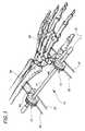
- FIG. 1is a perspective view of the apparatus for external fixation of bones according to the teachings of the preferred embodiment of the present invention shown in operative association with a wrist joint.
- FIG. 2is an exploded view of a first bone screw clamp assembly of the apparatus for external fixation of bones shown in FIG. 1 according to the teachings of the preferred embodiment of the present invention.
- FIG. 3is an end view of the first bone screw clamp assembly of the apparatus for external fixation of bones shown in FIG. 1 according to the teachings of the preferred embodiment of the present invention.
- FIGS. 4 (A)- 4 (D)are views of a base of the apparatus for external fixation of bones shown in FIG. 1 according to the teachings of the preferred embodiment of the present invention.
- FIGS. 5 (A)- 5 (C)are views of a cap member of the apparatus for external fixation of bones shown in FIG. 1 according to the teachings of the preferred embodiment of the present invention.
- FIGS. 6 (A)- 6 (B)are views of a spherical member of the apparatus for external fixation of bones shown in FIG. 1 according to the teachings of the preferred embodiment of the present invention.
- FIGS. 7 (A)- 7 (B)are views of a pin clamp of the first bone screw clamp assembly according to the teachings of the preferred embodiment of the present invention.
- FIGS. 8 (A)- 8 (B)are views of one of the rings of the apparatus for external fixation of bones shown in FIG. 1 according to the teachings of the preferred embodiment of the present invention.
- an apparatus 10 for the external fixation of bonesis shown constructed in accordance with the teachings of the preferred embodiment of the present invention.
- the apparatus 10is illustrated as being used for securing a bone fracture located in close proximity to the wrist joint such as a Colles fracture.
- the apparatus 10is used to secure bone portions in a fixed relationship so as to permit the fractured portions to fuse properly. While the apparatus 10 is shown in the environmental view of FIG. 1 in conjunction with a wrist joint, it will be appreciated that the apparatus 10 may be used for various other external fixation applications.
- the apparatus 10is shown to generally include a pair of bone screw clamp assemblies or clamping assemblies 12 and a connection member 14 .
- the bone screw clamping assemblies 12are identical.
- the connection member 14is a cylindrical rod that longitudinally extends along an axis 15 .
- Each of the bone screw clamp assemblies 12is illustrated to generally include a base 16 , a cap member 18 and a spherical member 20 . As will become understood more fully below, the base 16 and the cap member 18 cooperate to define a cavity for receiving the spherical member 20 . In certain applications, it may be desirable to use three or more bone screw clamp assemblies 12 .
- the bone screw clamp assembly 12is shown to define a passage 22 for receiving the longitudinal extending cylindrical rod 14 .
- the passage 22includes a first cylindrical portion 24 (see FIG. 4D) which defines a portion of the cavity for receiving the spherical member 20 and is generally cylindrical in shape.
- a second portion 26 of the passage 22is conical in shape and thereby adapted to accommodate angulation of the longitudinally extending rod 14 .
- An external surface 28 of the bone screw clamp assembly 12which circumferentially surrounds the first portion 24 of the passage 22 is externally threaded for threadably engaging the cap member 18 .
- the bone screw clamp assembly 12is further shown to include a portion 30 for receiving at least one bone screw 32 .
- each of the bone screw receiving portions 30is configured to receive two bone screws 32 .
- the bone screw clamping assemblies 12may be designed to accommodate 1 , 3 , or more bone screws 32 .
- the bone screw receiving portion 30defines a pair of apertures 34 for directly receiving the bone screws 32 .
- the apertures 34are oriented generally perpendicular to an axis passing through the passage 22 .
- a portion of the bone screw receiving portion 30is cutaway to provide a seat 36 which intersects both of the apertures 34 .
- the seat 36receives a bone screw clamp 38 which secures the pair of bone screws 32 to the portion 30 .
- the bone screw clamps 38are shown particularly in FIGS. 7A and 7B to partially define a pair of channels 40 for cooperating with the apertures 34 to receive the bone screws 32 .
- An aperture 42extends perpendicular to the channels 40 and aligns with a threaded aperture 44 provided in portion 30 .
- These apertures 42 and 44receive a set screw 46 for securing the bone screw clamp 38 to the portion 30 .
- the spherical member 20 of the present inventionis shown to include an aperture 50 for receiving the longitudinally extending rod 14 .
- the spherical member 20is shown to include a plurality of teeth 52 which radially extend in an inward direction toward the longitudinally extending rod 14 .
- the spherical member 20is further formed to include a plurality of slots 54 which extend generally parallel to the rod 14 .
- the slots 54each begin adjacent one of the ends of the spherical member 20 as defined by the aperture 50 and extend substantially but not completely across the spherical member 20 . Adjacent ones of the slots 54 begin on opposite sides of the spherical member 20 . Such a configuration facilitates compressibility of the spherical member 20 .
- the cap member 18is shown to include a passage 56 for receiving the longitudinally extending rod 14 .
- a first portion 58 of the passage 56is internally threaded for threadably engaging the externally threaded portion of the base 16 .
- the cap member 18is shown to include a first plurality of radially extending apertures 60 for receiving a tool (not shown) for driving the cap member 18 relative to the base 16 .
- the cap member 18is further shown to include a second plurality of radially extending apertures 62 .
- the apertures 62 of the second pluralityintersect the passage 56 and are each adapted to threadably receive a set screw.
- each of the bone screw clamp assemblies 12is shown to preferably include a pair of substantially identical rings 64 .
- One of the rings 64is disposed between the base 16 and the spherical member 20 and the other of the rings 64 is disposed between the cap member 18 and the spherical member 20 .
- the rings 64are shown to include an opening 66 including a cylindrical portion 68 and a tapered portion 70 .
- the tapered portion 70directly engages the spherical member 20 .
- the rings 64may be steel. However, other materials may be used.
- the bone screw clamping assemblies 12are mounted to the rod 14 for relative universal movement about a point through which the rod 14 passes.
- the point 72is defined by the spherical center of the spherical member 20 .
- the base 16 , cap member 18 , spherical member 20 and rings 64cooperate to provide a locking arrangement for precluding relative movement between the bone clamping assembly 12 and the rod 14 .
- the bone screw clamping assembly 12is permitted to longitudinally translate along the rod 14 and universally move relative to the rod 14 about the spherical center of the spherical member 20 .
- the cap member 18When the cap member 18 is rotated relative to the base 16 in a first direction (clockwise as shown in FIG. 3 ), the cap member 18 further threadably engages the base 16 thereby drawing the rings 64 together so as to clamp down on the spherical member 20 .
Landscapes
- Health & Medical Sciences (AREA)
- Orthopedic Medicine & Surgery (AREA)
- Life Sciences & Earth Sciences (AREA)
- Surgery (AREA)
- Biomedical Technology (AREA)
- Engineering & Computer Science (AREA)
- Nuclear Medicine, Radiotherapy & Molecular Imaging (AREA)
- Heart & Thoracic Surgery (AREA)
- Medical Informatics (AREA)
- Molecular Biology (AREA)
- Animal Behavior & Ethology (AREA)
- General Health & Medical Sciences (AREA)
- Public Health (AREA)
- Veterinary Medicine (AREA)
- Surgical Instruments (AREA)
Abstract
Description
Claims (24)
Priority Applications (1)
| Application Number | Priority Date | Filing Date | Title |
|---|---|---|---|
| US09/790,770US6482206B2 (en) | 2001-02-22 | 2001-02-22 | Method and apparatus for external fixation of bones |
Applications Claiming Priority (1)
| Application Number | Priority Date | Filing Date | Title |
|---|---|---|---|
| US09/790,770US6482206B2 (en) | 2001-02-22 | 2001-02-22 | Method and apparatus for external fixation of bones |
Publications (2)
| Publication Number | Publication Date |
|---|---|
| US20020115998A1 US20020115998A1 (en) | 2002-08-22 |
| US6482206B2true US6482206B2 (en) | 2002-11-19 |
Family
ID=25151693
Family Applications (1)
| Application Number | Title | Priority Date | Filing Date |
|---|---|---|---|
| US09/790,770Expired - LifetimeUS6482206B2 (en) | 2001-02-22 | 2001-02-22 | Method and apparatus for external fixation of bones |
Country Status (1)
| Country | Link |
|---|---|
| US (1) | US6482206B2 (en) |
Cited By (30)
| Publication number | Priority date | Publication date | Assignee | Title |
|---|---|---|---|---|
| US20030191467A1 (en)* | 2000-12-14 | 2003-10-09 | Hoffmann-Clair Mindy L. | Multipin clamp and rod attachment |
| US20040133200A1 (en)* | 2002-11-15 | 2004-07-08 | Ruch David S. | Apparatus and method for maintaining bones in a healing position |
| US20060241590A1 (en)* | 2005-04-25 | 2006-10-26 | Jean-Noel Bordeaux | Outrigger with locking mechanism |
| US20060247622A1 (en)* | 2005-04-27 | 2006-11-02 | Maughan Thomas J | Bone fixation apparatus |
| US7507240B2 (en) | 2005-03-18 | 2009-03-24 | Ron Anthon Olsen | Adjustable splint for osteosynthesis |
| US20090125068A1 (en)* | 2003-02-28 | 2009-05-14 | Estrada Jr Hector Mark | Apparatus for Dynamic External Fixation of Distal Radius and Wrist Fractures |
| US20090299368A1 (en)* | 2005-04-01 | 2009-12-03 | Tantum Ag | Fixation Device for Stably Interlinking At Least Two Bone Fragments of a Broken Bone and Corresponding Fixation Element and Kit |
| US7731738B2 (en) | 2005-12-09 | 2010-06-08 | Orthopro, Llc | Cannulated screw |
| USD663030S1 (en) | 2011-06-14 | 2012-07-03 | Styker Trauma SA | Fixation clamp |
| US20120232560A1 (en)* | 2011-03-09 | 2012-09-13 | Mutlaq Almutairi | Orthopedic Surgical Pin Positioning Device |
| USD682426S1 (en) | 2011-06-14 | 2013-05-14 | Stryker Trauma Sa | Fixation clamp |
| USD683461S1 (en) | 2010-12-14 | 2013-05-28 | Stryker Trauma Sa | Hinge coupling |
| US8685023B2 (en) | 2010-12-14 | 2014-04-01 | Stryker Trauma Sa | Fixation clamp |
| USD704840S1 (en) | 2010-12-14 | 2014-05-13 | Stryker Trauma Sa | Hinge coupling |
| US8827998B2 (en) | 2010-12-14 | 2014-09-09 | Stryker Trauma Sa | Fixation clamp |
| USD720853S1 (en) | 2010-12-14 | 2015-01-06 | Stryker Trauma Sa | Fixation clamp |
| US8945129B2 (en) | 2010-12-14 | 2015-02-03 | Stryker Trauma Sa | Fixation clamp with thumbwheel |
| US9066757B2 (en) | 2009-08-10 | 2015-06-30 | Virak Orthopedic Research Llc | Orthopedic external fixator and method of use |
| US9301782B2 (en) | 2012-09-04 | 2016-04-05 | Zimmer, Inc. | External fixation |
| US20160278813A1 (en)* | 2013-03-15 | 2016-09-29 | Dne, Llc | External bone fixation system |
| RU170362U1 (en)* | 2016-08-26 | 2017-04-24 | Владимир Николаевич Панченко | Compression-distraction device for the treatment of fractures of the facial skeleton and the base of the skull |
| RU172782U1 (en)* | 2016-08-01 | 2017-07-24 | Георгий Шотавич Голубев | DEVICE FOR TREATMENT OF DISTAL METAEPHYTHESIS Fractures Fractures |
| RU172833U1 (en)* | 2016-02-17 | 2017-07-26 | Радмир Амирович Саубанов | Device for osteosynthesis in metaphysical fractures |
| US9827011B2 (en)* | 2013-03-15 | 2017-11-28 | Biomet Manufacturing, Llc | Polyaxial pivot housing for external fixation system |
| US9924969B2 (en) | 2012-09-04 | 2018-03-27 | Zimmer, Inc. | External fixation |
| US9962187B2 (en) | 2014-08-11 | 2018-05-08 | Zimmer, Inc. | External fixation |
| US9962188B2 (en) | 2013-10-29 | 2018-05-08 | Cardinal Health 247. Inc. | External fixation system and methods of use |
| US10258378B2 (en) | 2013-03-15 | 2019-04-16 | Dne, Llc | External bone fixation system |
| US11134988B2 (en) | 2015-06-17 | 2021-10-05 | Zimmer, Inc. | Ankle fixation system |
| US11291476B2 (en) | 2016-06-10 | 2022-04-05 | Dne, Llc | External bone fixation system |
Families Citing this family (15)
| Publication number | Priority date | Publication date | Assignee | Title |
|---|---|---|---|---|
| RU2261678C1 (en)* | 2004-12-09 | 2005-10-10 | Голубев Валерий Григорьевич | Device for carrying out tubular bone metaphysis fracture osteosynthesis |
| RU2299034C2 (en)* | 2005-05-30 | 2007-05-20 | Дагестанская государственная медицинская академия | Device for destructive osteosynthesis of radiocarpal articulation |
| RU2299033C2 (en)* | 2005-05-30 | 2007-05-20 | Дагестанская государственная медицинская академия | Apparatus for urgent out-of-site osteosynthesis of shin fractures |
| CH714281B1 (en)* | 2006-03-03 | 2019-04-30 | Dr Oskar E Illi Prof | External fixator for repositioning and stabilizing bone fragments. |
| RU2322211C1 (en)* | 2006-06-08 | 2008-04-20 | Виталий Михайлович Михайлов | Rod apparatus for intrabone ostheosynthesis |
| RU2325866C1 (en)* | 2006-10-09 | 2008-06-10 | Джевдет Энвербекович Купкенов | Device for reposition and fixation of fractures of anticnemion bones |
| GB2444907A (en)* | 2006-12-20 | 2008-06-25 | Promedics Ltd | A joint fixator |
| RU2327431C1 (en)* | 2006-12-26 | 2008-06-27 | Джевдет Энвербекович Купкенов | Apparatus for reduction and fixation of leg fracture |
| AU2008318535B2 (en)* | 2007-10-31 | 2014-06-19 | Wright Medical Technology, Inc. | Orthopedic device |
| US8282636B2 (en) | 2009-08-10 | 2012-10-09 | Imds Corporation | Orthopedic external fixator and method of use |
| EP2319436B1 (en)* | 2009-11-06 | 2013-02-13 | ORTHOFIX S.r.l. | Clamp for external orthopaedic fixing device |
| RU2463989C1 (en)* | 2011-06-27 | 2012-10-20 | Государственное образовательное учреждение высшего профессионального образования "Дагестанская государственная медицинская академия федерального агентства по здравоохранению и социальному развитию" | Device for closed reposition of sagging tibial condyle |
| ITVR20130013A1 (en)* | 2013-01-21 | 2014-07-22 | Tecres Spa | EXTERNAL FIXING DEVICE FOR THE TREATMENT OF BONE FRACTURES |
| CN105877825B (en)* | 2016-05-03 | 2018-05-25 | 中国人民解放军北京军区总医院 | Wartime external fixing rack |
| WO2020095217A1 (en)* | 2018-11-06 | 2020-05-14 | Moradi Ali | External orthopedic fixation device |
Citations (16)
| Publication number | Priority date | Publication date | Assignee | Title |
|---|---|---|---|---|
| US4483334A (en)* | 1983-04-11 | 1984-11-20 | Murray William M | External fixation device |
| US4662365A (en) | 1982-12-03 | 1987-05-05 | Ortopedia Gmbh | Device for the external fixation of bone fragments |
| US4848368A (en) | 1988-04-25 | 1989-07-18 | Kronner Richard F | Universal external fixation frame assembly |
| US5108394A (en) | 1989-09-08 | 1992-04-28 | Kabushiki Kaisha Nagano Keiki Seisakusho | Bone fixing device |
| US5403313A (en) | 1993-07-29 | 1995-04-04 | Lin; Chih-I | External fixation device for fractured bone |
| US5443464A (en)* | 1993-02-16 | 1995-08-22 | Memphis Orthopaedic Design, Inc. | External fixator apparatus |
| US5630815A (en) | 1994-08-05 | 1997-05-20 | Pohl; Anthony P. | External fixator for military use |
| US5683389A (en) | 1994-12-05 | 1997-11-04 | Smith & Nephew, Inc. | External fixator for distal radius fractures |
| US5690633A (en) | 1994-09-23 | 1997-11-25 | Smith & Nephew Richards, Inc. | Orthopedic fracture fixation device |
| US5769851A (en)* | 1994-09-03 | 1998-06-23 | Veith; Wolfgang | External fixator |
| US5797908A (en) | 1997-02-04 | 1998-08-25 | Bristol-Myers Squibb Company | External fixator assembly and clamp therefor |
| US5891144A (en) | 1996-05-10 | 1999-04-06 | Jaquet Orthopedie S.A. | External fixator |
| US5921985A (en) | 1998-02-10 | 1999-07-13 | Texas Scottish Rite Hospital | External fixation device and method |
| US6022348A (en)* | 1997-11-30 | 2000-02-08 | Spitzer; Daniel | Clamping connection for medical equipment and apparatus |
| US6102911A (en) | 1997-02-13 | 2000-08-15 | Orthofix S.R.L. | Orthopaedic apparatus, particularly for the surgical correction of bone deformities |
| US6217577B1 (en)* | 1999-01-21 | 2001-04-17 | Medicalplastic S.R.L. | Outer fixing device for orthopedics and traumatology |
- 2001
- 2001-02-22USUS09/790,770patent/US6482206B2/ennot_activeExpired - Lifetime
Patent Citations (16)
| Publication number | Priority date | Publication date | Assignee | Title |
|---|---|---|---|---|
| US4662365A (en) | 1982-12-03 | 1987-05-05 | Ortopedia Gmbh | Device for the external fixation of bone fragments |
| US4483334A (en)* | 1983-04-11 | 1984-11-20 | Murray William M | External fixation device |
| US4848368A (en) | 1988-04-25 | 1989-07-18 | Kronner Richard F | Universal external fixation frame assembly |
| US5108394A (en) | 1989-09-08 | 1992-04-28 | Kabushiki Kaisha Nagano Keiki Seisakusho | Bone fixing device |
| US5443464A (en)* | 1993-02-16 | 1995-08-22 | Memphis Orthopaedic Design, Inc. | External fixator apparatus |
| US5403313A (en) | 1993-07-29 | 1995-04-04 | Lin; Chih-I | External fixation device for fractured bone |
| US5630815A (en) | 1994-08-05 | 1997-05-20 | Pohl; Anthony P. | External fixator for military use |
| US5769851A (en)* | 1994-09-03 | 1998-06-23 | Veith; Wolfgang | External fixator |
| US5690633A (en) | 1994-09-23 | 1997-11-25 | Smith & Nephew Richards, Inc. | Orthopedic fracture fixation device |
| US5683389A (en) | 1994-12-05 | 1997-11-04 | Smith & Nephew, Inc. | External fixator for distal radius fractures |
| US5891144A (en) | 1996-05-10 | 1999-04-06 | Jaquet Orthopedie S.A. | External fixator |
| US5797908A (en) | 1997-02-04 | 1998-08-25 | Bristol-Myers Squibb Company | External fixator assembly and clamp therefor |
| US6102911A (en) | 1997-02-13 | 2000-08-15 | Orthofix S.R.L. | Orthopaedic apparatus, particularly for the surgical correction of bone deformities |
| US6022348A (en)* | 1997-11-30 | 2000-02-08 | Spitzer; Daniel | Clamping connection for medical equipment and apparatus |
| US5921985A (en) | 1998-02-10 | 1999-07-13 | Texas Scottish Rite Hospital | External fixation device and method |
| US6217577B1 (en)* | 1999-01-21 | 2001-04-17 | Medicalplastic S.R.L. | Outer fixing device for orthopedics and traumatology |
Cited By (54)
| Publication number | Priority date | Publication date | Assignee | Title |
|---|---|---|---|---|
| US7699848B2 (en) | 2000-12-14 | 2010-04-20 | Synthes Usa, Llc | Multipin clamp and rod attachment |
| US20030191468A1 (en)* | 2000-12-14 | 2003-10-09 | Synthes U.S.A. | Multipin clamp and rod attachment |
| US7041103B2 (en) | 2000-12-14 | 2006-05-09 | Synthes (Usa) | Multipin clamp and rod attachment |
| US20030191467A1 (en)* | 2000-12-14 | 2003-10-09 | Hoffmann-Clair Mindy L. | Multipin clamp and rod attachment |
| US20040133200A1 (en)* | 2002-11-15 | 2004-07-08 | Ruch David S. | Apparatus and method for maintaining bones in a healing position |
| US20090125068A1 (en)* | 2003-02-28 | 2009-05-14 | Estrada Jr Hector Mark | Apparatus for Dynamic External Fixation of Distal Radius and Wrist Fractures |
| US7507240B2 (en) | 2005-03-18 | 2009-03-24 | Ron Anthon Olsen | Adjustable splint for osteosynthesis |
| US7575575B2 (en) | 2005-03-18 | 2009-08-18 | Ron Anthon Olsen | Adjustable splint for osteosynthesis with modular components |
| US7588571B2 (en) | 2005-03-18 | 2009-09-15 | Ron Anthon Olsen | Adjustable splint for osteosynthesis with modular joint |
| US8147490B2 (en)* | 2005-04-01 | 2012-04-03 | Tantum Ag | Fixation device for stably interlinking at least two bone fragments of a broken bone and corresponding fixation element and kit |
| US20090299368A1 (en)* | 2005-04-01 | 2009-12-03 | Tantum Ag | Fixation Device for Stably Interlinking At Least Two Bone Fragments of a Broken Bone and Corresponding Fixation Element and Kit |
| US20060241590A1 (en)* | 2005-04-25 | 2006-10-26 | Jean-Noel Bordeaux | Outrigger with locking mechanism |
| US7722609B2 (en) | 2005-04-25 | 2010-05-25 | Synthes Usa, Llc | Outrigger with locking mechanism |
| US9273715B2 (en) | 2005-04-25 | 2016-03-01 | DePuy Synthes Products, Inc. | Outrigger with locking mechanism |
| US20060247622A1 (en)* | 2005-04-27 | 2006-11-02 | Maughan Thomas J | Bone fixation apparatus |
| US8758343B2 (en) | 2005-04-27 | 2014-06-24 | DePuy Synthes Products, LLC | Bone fixation apparatus |
| US7731738B2 (en) | 2005-12-09 | 2010-06-08 | Orthopro, Llc | Cannulated screw |
| US9066757B2 (en) | 2009-08-10 | 2015-06-30 | Virak Orthopedic Research Llc | Orthopedic external fixator and method of use |
| US8945129B2 (en) | 2010-12-14 | 2015-02-03 | Stryker Trauma Sa | Fixation clamp with thumbwheel |
| US9402651B2 (en) | 2010-12-14 | 2016-08-02 | Stryker European Holdings I, Llc | Fixation clamp |
| US8685023B2 (en) | 2010-12-14 | 2014-04-01 | Stryker Trauma Sa | Fixation clamp |
| USD704840S1 (en) | 2010-12-14 | 2014-05-13 | Stryker Trauma Sa | Hinge coupling |
| USD683461S1 (en) | 2010-12-14 | 2013-05-28 | Stryker Trauma Sa | Hinge coupling |
| US8827998B2 (en) | 2010-12-14 | 2014-09-09 | Stryker Trauma Sa | Fixation clamp |
| USD720853S1 (en) | 2010-12-14 | 2015-01-06 | Stryker Trauma Sa | Fixation clamp |
| US9259242B2 (en) | 2010-12-14 | 2016-02-16 | Stryker Trauma Sa | Fixation clamp |
| US9050135B2 (en) | 2010-12-14 | 2015-06-09 | Stryker Trauma Sa | Fixation clamp with thumbwheel |
| US20120232560A1 (en)* | 2011-03-09 | 2012-09-13 | Mutlaq Almutairi | Orthopedic Surgical Pin Positioning Device |
| US8636745B2 (en)* | 2011-03-09 | 2014-01-28 | Mutlaq Almutairi | Orthopedic surgical pin positioning device |
| USD682426S1 (en) | 2011-06-14 | 2013-05-14 | Stryker Trauma Sa | Fixation clamp |
| USD663030S1 (en) | 2011-06-14 | 2012-07-03 | Styker Trauma SA | Fixation clamp |
| US9301782B2 (en) | 2012-09-04 | 2016-04-05 | Zimmer, Inc. | External fixation |
| US9924969B2 (en) | 2012-09-04 | 2018-03-27 | Zimmer, Inc. | External fixation |
| US10905469B2 (en) | 2012-09-04 | 2021-02-02 | Zimmer, Inc. | External fixation |
| US10433873B2 (en) | 2012-09-04 | 2019-10-08 | Zimmer, Inc. | External fixation |
| US10010348B2 (en) | 2012-09-04 | 2018-07-03 | Zimmer, Inc. | External fixation |
| US10299830B2 (en) | 2013-03-15 | 2019-05-28 | Biomet Manufacturing, Llc | Clamping assembly for external fixation system |
| US11259843B2 (en) | 2013-03-15 | 2022-03-01 | Dne, Llc | External bone fixation system |
| US11986218B2 (en)* | 2013-03-15 | 2024-05-21 | Trilliant Surgical, Llc | External bone fixation system |
| US20220211415A1 (en)* | 2013-03-15 | 2022-07-07 | Dne, Llc | External bone fixation system |
| US9827011B2 (en)* | 2013-03-15 | 2017-11-28 | Biomet Manufacturing, Llc | Polyaxial pivot housing for external fixation system |
| US10022152B2 (en)* | 2013-03-15 | 2018-07-17 | Dne, Llc | External bone fixation system |
| US10258378B2 (en) | 2013-03-15 | 2019-04-16 | Dne, Llc | External bone fixation system |
| US20160278813A1 (en)* | 2013-03-15 | 2016-09-29 | Dne, Llc | External bone fixation system |
| US10687853B2 (en) | 2013-03-15 | 2020-06-23 | Dne, Llc | External bone fixation system |
| US9962188B2 (en) | 2013-10-29 | 2018-05-08 | Cardinal Health 247. Inc. | External fixation system and methods of use |
| US10543019B2 (en) | 2014-08-11 | 2020-01-28 | Zimmer, Inc. | External fixation |
| US9962187B2 (en) | 2014-08-11 | 2018-05-08 | Zimmer, Inc. | External fixation |
| US11134988B2 (en) | 2015-06-17 | 2021-10-05 | Zimmer, Inc. | Ankle fixation system |
| RU172833U1 (en)* | 2016-02-17 | 2017-07-26 | Радмир Амирович Саубанов | Device for osteosynthesis in metaphysical fractures |
| US11291476B2 (en) | 2016-06-10 | 2022-04-05 | Dne, Llc | External bone fixation system |
| US12016592B2 (en) | 2016-06-10 | 2024-06-25 | Trilliant Surgical, Llc | External bone fixation system |
| RU172782U1 (en)* | 2016-08-01 | 2017-07-24 | Георгий Шотавич Голубев | DEVICE FOR TREATMENT OF DISTAL METAEPHYTHESIS Fractures Fractures |
| RU170362U1 (en)* | 2016-08-26 | 2017-04-24 | Владимир Николаевич Панченко | Compression-distraction device for the treatment of fractures of the facial skeleton and the base of the skull |
Also Published As
| Publication number | Publication date |
|---|---|
| US20020115998A1 (en) | 2002-08-22 |
Similar Documents
| Publication | Publication Date | Title |
|---|---|---|
| US6482206B2 (en) | Method and apparatus for external fixation of bones | |
| EP1229846B1 (en) | External fixation system | |
| US6010501A (en) | Method and apparatus for external fixation of small bones | |
| US6152925A (en) | Method and apparatus for external fixation of an elbow | |
| US5976136A (en) | Method and apparatus for external bone fixator | |
| US6616664B2 (en) | Clamp assembly for an external fixation system | |
| US5743898A (en) | Method and apparatus for external fixation of small bones | |
| US7261713B2 (en) | Adjustable fixator | |
| JP2024028709A (en) | external bone fixation system | |
| US6432109B1 (en) | Connection device for osteosynthesis | |
| EP2967673B1 (en) | External fixation system | |
| US7699848B2 (en) | Multipin clamp and rod attachment | |
| CA2823579C (en) | Clamp for temporary or definitive external orthopaedic fixation, and external fixation system comprising said clamp | |
| US5676664A (en) | Orthopaedic distractor and/or fixator | |
| US5961515A (en) | External skeletal fixation system | |
| WO1999060950A2 (en) | Ring system for external fixation of bone and related method | |
| CA2208054A1 (en) | External fixator for distal radius fractures | |
| WO1999029247A1 (en) | Method and apparatus for external fixation of an ankle | |
| WO1994023662A2 (en) | Disposable external fixator | |
| US9339296B2 (en) | Joint distraction system | |
| EP1482845B1 (en) | Clamp assembly for an external fixation system | |
| HK1186948B (en) | Clamp for temporary or definitive external orthopaedic fixation, and external fixation system comprising said clamp | |
| HK1009735B (en) | Method and apparatus for external fixation of small bones |
Legal Events
| Date | Code | Title | Description |
|---|---|---|---|
| AS | Assignment | Owner name:BIOMET, INC., INDIANA Free format text:ASSIGNMENT OF ASSIGNORS INTEREST;ASSIGNOR:SCHOENEFELD, RYAN J.;REEL/FRAME:011558/0501 Effective date:20010220 | |
| STCF | Information on status: patent grant | Free format text:PATENTED CASE | |
| CC | Certificate of correction | ||
| FPAY | Fee payment | Year of fee payment:4 | |
| AS | Assignment | Owner name:BIOMET MANUFACTURING CORP., INDIANA Free format text:ASSIGNMENT OF ASSIGNORS INTEREST;ASSIGNOR:BIOMET, INC.;REEL/FRAME:019043/0792 Effective date:19990601 | |
| AS | Assignment | Owner name:BIOMET MANUFACTURING CORP., INDIANA Free format text:ASSIGNMENT OF ASSIGNORS INTEREST;ASSIGNOR:BIOMET, INC.;REEL/FRAME:019287/0413 Effective date:20070514 | |
| AS | Assignment | Owner name:BANK OF AMERICA, N.A., AS ADMINISTRATIVE AGENT FOR Free format text:SECURITY AGREEMENT;ASSIGNORS:LVB ACQUISITION, INC.;BIOMET, INC.;REEL/FRAME:020362/0001 Effective date:20070925 | |
| FPAY | Fee payment | Year of fee payment:8 | |
| AS | Assignment | Owner name:BIOMET MANUFACTURING, LLC, INDIANA Free format text:CHANGE OF NAME;ASSIGNOR:BIOMET MANUFACTURING CORPORATION;REEL/FRAME:030656/0702 Effective date:20130603 | |
| FPAY | Fee payment | Year of fee payment:12 | |
| AS | Assignment | Owner name:LVB ACQUISITION, INC., INDIANA Free format text:RELEASE OF SECURITY INTEREST IN PATENTS RECORDED AT REEL 020362/ FRAME 0001;ASSIGNOR:BANK OF AMERICA, N.A., AS ADMINISTRATIVE AGENT;REEL/FRAME:037155/0133 Effective date:20150624 Owner name:BIOMET, INC., INDIANA Free format text:RELEASE OF SECURITY INTEREST IN PATENTS RECORDED AT REEL 020362/ FRAME 0001;ASSIGNOR:BANK OF AMERICA, N.A., AS ADMINISTRATIVE AGENT;REEL/FRAME:037155/0133 Effective date:20150624 |