US6482186B1 - Reusable medication delivery device - Google Patents
Reusable medication delivery deviceDownload PDFInfo
- Publication number
- US6482186B1 US6482186B1US09/672,103US67210300AUS6482186B1US 6482186 B1US6482186 B1US 6482186B1US 67210300 AUS67210300 AUS 67210300AUS 6482186 B1US6482186 B1US 6482186B1
- Authority
- US
- United States
- Prior art keywords
- ampule
- housing
- sleeve
- flexible member
- dosage
- Prior art date
- Legal status (The legal status is an assumption and is not a legal conclusion. Google has not performed a legal analysis and makes no representation as to the accuracy of the status listed.)
- Expired - Fee Related, expires
Links
- 239000003814drugSubstances0.000titleclaimsabstractdescription55
- 229940079593drugDrugs0.000titleclaimsabstractdescription49
- 238000002347injectionMethods0.000claimsabstractdescription33
- 239000007924injectionSubstances0.000claimsabstractdescription33
- 230000007246mechanismEffects0.000claimsabstractdescription21
- 239000012530fluidSubstances0.000claimsabstractdescription10
- 239000003708ampulSubstances0.000claimsdescription78
- 238000001802infusionMethods0.000claimsdescription37
- 238000007920subcutaneous administrationMethods0.000claimsdescription13
- 238000000034methodMethods0.000claimsdescription11
- 238000004891communicationMethods0.000claimsdescription5
- 238000003780insertionMethods0.000claimsdescription4
- 230000037431insertionEffects0.000claimsdescription4
- NOESYZHRGYRDHS-UHFFFAOYSA-NinsulinChemical compoundN1C(=O)C(NC(=O)C(CCC(N)=O)NC(=O)C(CCC(O)=O)NC(=O)C(C(C)C)NC(=O)C(NC(=O)CN)C(C)CC)CSSCC(C(NC(CO)C(=O)NC(CC(C)C)C(=O)NC(CC=2C=CC(O)=CC=2)C(=O)NC(CCC(N)=O)C(=O)NC(CC(C)C)C(=O)NC(CCC(O)=O)C(=O)NC(CC(N)=O)C(=O)NC(CC=2C=CC(O)=CC=2)C(=O)NC(CSSCC(NC(=O)C(C(C)C)NC(=O)C(CC(C)C)NC(=O)C(CC=2C=CC(O)=CC=2)NC(=O)C(CC(C)C)NC(=O)C(C)NC(=O)C(CCC(O)=O)NC(=O)C(C(C)C)NC(=O)C(CC(C)C)NC(=O)C(CC=2NC=NC=2)NC(=O)C(CO)NC(=O)CNC2=O)C(=O)NCC(=O)NC(CCC(O)=O)C(=O)NC(CCCNC(N)=N)C(=O)NCC(=O)NC(CC=3C=CC=CC=3)C(=O)NC(CC=3C=CC=CC=3)C(=O)NC(CC=3C=CC(O)=CC=3)C(=O)NC(C(C)O)C(=O)N3C(CCC3)C(=O)NC(CCCCN)C(=O)NC(C)C(O)=O)C(=O)NC(CC(N)=O)C(O)=O)=O)NC(=O)C(C(C)CC)NC(=O)C(CO)NC(=O)C(C(C)O)NC(=O)C1CSSCC2NC(=O)C(CC(C)C)NC(=O)C(NC(=O)C(CCC(N)=O)NC(=O)C(CC(N)=O)NC(=O)C(NC(=O)C(N)CC=1C=CC=CC=1)C(C)C)CC1=CN=CN1NOESYZHRGYRDHS-UHFFFAOYSA-N0.000abstractdescription48
- 102000004877InsulinHuman genes0.000abstractdescription24
- 108090001061InsulinProteins0.000abstractdescription24
- 229940125396insulinDrugs0.000abstractdescription24
- 238000002560therapeutic procedureMethods0.000description8
- 206010012601diabetes mellitusDiseases0.000description7
- 230000008901benefitEffects0.000description5
- 230000006835compressionEffects0.000description5
- 238000007906compressionMethods0.000description5
- WQZGKKKJIJFFOK-GASJEMHNSA-NGlucoseNatural productsOC[C@H]1OC(O)[C@H](O)[C@@H](O)[C@@H]1OWQZGKKKJIJFFOK-GASJEMHNSA-N0.000description4
- 239000008103glucoseSubstances0.000description4
- 238000012360testing methodMethods0.000description4
- 230000008859changeEffects0.000description3
- 238000004804windingMethods0.000description3
- 230000000295complement effectEffects0.000description2
- 238000013461designMethods0.000description2
- 201000010099diseaseDiseases0.000description2
- 208000037265diseases, disorders, signs and symptomsDiseases0.000description2
- 230000009977dual effectEffects0.000description2
- 230000006870functionEffects0.000description2
- 208000015181infectious diseaseDiseases0.000description2
- 230000000670limiting effectEffects0.000description2
- 239000007788liquidSubstances0.000description2
- 238000007726management methodMethods0.000description2
- 229940126701oral medicationDrugs0.000description2
- 230000036961partial effectEffects0.000description2
- 230000001105regulatory effectEffects0.000description2
- 238000010254subcutaneous injectionMethods0.000description2
- 239000007929subcutaneous injectionSubstances0.000description2
- 238000003462Bender reactionMethods0.000description1
- 208000002249Diabetes ComplicationsDiseases0.000description1
- 206010022079Injection site irritationDiseases0.000description1
- 206010067584Type 1 diabetes mellitusDiseases0.000description1
- 206010057362UnderdoseDiseases0.000description1
- 239000000470constituentSubstances0.000description1
- 230000001276controlling effectEffects0.000description1
- 238000002716delivery methodMethods0.000description1
- 238000006073displacement reactionMethods0.000description1
- -1e.g.Substances0.000description1
- 210000005069earsAnatomy0.000description1
- 238000005516engineering processMethods0.000description1
- 239000011521glassSubstances0.000description1
- 239000003292glueSubstances0.000description1
- 230000036541healthEffects0.000description1
- 230000036512infertilityEffects0.000description1
- 230000003993interactionEffects0.000description1
- 230000002452interceptive effectEffects0.000description1
- 230000007794irritationEffects0.000description1
- 230000007774longtermEffects0.000description1
- 239000000463materialSubstances0.000description1
- 230000013011matingEffects0.000description1
- 230000000737periodic effectEffects0.000description1
- 230000002572peristaltic effectEffects0.000description1
- 230000008569processEffects0.000description1
- 238000005086pumpingMethods0.000description1
- 230000009467reductionEffects0.000description1
- 230000002829reductive effectEffects0.000description1
- 230000004044responseEffects0.000description1
- 230000000717retained effectEffects0.000description1
- 229910001220stainless steelInorganic materials0.000description1
- 239000010935stainless steelSubstances0.000description1
- 238000010561standard procedureMethods0.000description1
- 239000000126substanceSubstances0.000description1
- 230000000153supplemental effectEffects0.000description1
- 230000000007visual effectEffects0.000description1
- 238000011179visual inspectionMethods0.000description1
- 238000003466weldingMethods0.000description1
Images


Classifications
- A—HUMAN NECESSITIES
- A61—MEDICAL OR VETERINARY SCIENCE; HYGIENE
- A61M—DEVICES FOR INTRODUCING MEDIA INTO, OR ONTO, THE BODY; DEVICES FOR TRANSDUCING BODY MEDIA OR FOR TAKING MEDIA FROM THE BODY; DEVICES FOR PRODUCING OR ENDING SLEEP OR STUPOR
- A61M5/00—Devices for bringing media into the body in a subcutaneous, intra-vascular or intramuscular way; Accessories therefor, e.g. filling or cleaning devices, arm-rests
- A61M5/14—Infusion devices, e.g. infusing by gravity; Blood infusion; Accessories therefor
- A61M5/142—Pressure infusion, e.g. using pumps
- A61M5/145—Pressure infusion, e.g. using pumps using pressurised reservoirs, e.g. pressurised by means of pistons
- A61M5/1452—Pressure infusion, e.g. using pumps using pressurised reservoirs, e.g. pressurised by means of pistons pressurised by means of pistons
- A61M5/14566—Pressure infusion, e.g. using pumps using pressurised reservoirs, e.g. pressurised by means of pistons pressurised by means of pistons with a replaceable reservoir for receiving a piston rod of the pump
- A—HUMAN NECESSITIES
- A61—MEDICAL OR VETERINARY SCIENCE; HYGIENE
- A61M—DEVICES FOR INTRODUCING MEDIA INTO, OR ONTO, THE BODY; DEVICES FOR TRANSDUCING BODY MEDIA OR FOR TAKING MEDIA FROM THE BODY; DEVICES FOR PRODUCING OR ENDING SLEEP OR STUPOR
- A61M5/00—Devices for bringing media into the body in a subcutaneous, intra-vascular or intramuscular way; Accessories therefor, e.g. filling or cleaning devices, arm-rests
- A61M5/178—Syringes
- A61M5/31—Details
- A61M5/315—Pistons; Piston-rods; Guiding, blocking or restricting the movement of the rod or piston; Appliances on the rod for facilitating dosing ; Dosing mechanisms
- A61M5/31511—Piston or piston-rod constructions, e.g. connection of piston with piston-rod
- A—HUMAN NECESSITIES
- A61—MEDICAL OR VETERINARY SCIENCE; HYGIENE
- A61M—DEVICES FOR INTRODUCING MEDIA INTO, OR ONTO, THE BODY; DEVICES FOR TRANSDUCING BODY MEDIA OR FOR TAKING MEDIA FROM THE BODY; DEVICES FOR PRODUCING OR ENDING SLEEP OR STUPOR
- A61M5/00—Devices for bringing media into the body in a subcutaneous, intra-vascular or intramuscular way; Accessories therefor, e.g. filling or cleaning devices, arm-rests
- A61M5/178—Syringes
- A61M5/31—Details
- A61M5/315—Pistons; Piston-rods; Guiding, blocking or restricting the movement of the rod or piston; Appliances on the rod for facilitating dosing ; Dosing mechanisms
- A61M5/31533—Dosing mechanisms, i.e. setting a dose
- A61M5/31545—Setting modes for dosing
- A61M5/31548—Mechanically operated dose setting member
- A61M5/3155—Mechanically operated dose setting member by rotational movement of dose setting member, e.g. during setting or filling of a syringe
- A61M5/31551—Mechanically operated dose setting member by rotational movement of dose setting member, e.g. during setting or filling of a syringe including axial movement of dose setting member
- A—HUMAN NECESSITIES
- A61—MEDICAL OR VETERINARY SCIENCE; HYGIENE
- A61M—DEVICES FOR INTRODUCING MEDIA INTO, OR ONTO, THE BODY; DEVICES FOR TRANSDUCING BODY MEDIA OR FOR TAKING MEDIA FROM THE BODY; DEVICES FOR PRODUCING OR ENDING SLEEP OR STUPOR
- A61M5/00—Devices for bringing media into the body in a subcutaneous, intra-vascular or intramuscular way; Accessories therefor, e.g. filling or cleaning devices, arm-rests
- A61M5/178—Syringes
- A61M5/31—Details
- A61M5/315—Pistons; Piston-rods; Guiding, blocking or restricting the movement of the rod or piston; Appliances on the rod for facilitating dosing ; Dosing mechanisms
- A61M5/31565—Administration mechanisms, i.e. constructional features, modes of administering a dose
- A61M5/31576—Constructional features or modes of drive mechanisms for piston rods
- A61M5/31578—Constructional features or modes of drive mechanisms for piston rods based on axial translation, i.e. components directly operatively associated and axially moved with plunger rod
- A61M5/3158—Constructional features or modes of drive mechanisms for piston rods based on axial translation, i.e. components directly operatively associated and axially moved with plunger rod performed by axially moving actuator operated by user, e.g. an injection button
- A—HUMAN NECESSITIES
- A61—MEDICAL OR VETERINARY SCIENCE; HYGIENE
- A61M—DEVICES FOR INTRODUCING MEDIA INTO, OR ONTO, THE BODY; DEVICES FOR TRANSDUCING BODY MEDIA OR FOR TAKING MEDIA FROM THE BODY; DEVICES FOR PRODUCING OR ENDING SLEEP OR STUPOR
- A61M5/00—Devices for bringing media into the body in a subcutaneous, intra-vascular or intramuscular way; Accessories therefor, e.g. filling or cleaning devices, arm-rests
- A61M5/178—Syringes
- A61M5/31—Details
- A61M2005/3125—Details specific display means, e.g. to indicate dose setting
- A—HUMAN NECESSITIES
- A61—MEDICAL OR VETERINARY SCIENCE; HYGIENE
- A61M—DEVICES FOR INTRODUCING MEDIA INTO, OR ONTO, THE BODY; DEVICES FOR TRANSDUCING BODY MEDIA OR FOR TAKING MEDIA FROM THE BODY; DEVICES FOR PRODUCING OR ENDING SLEEP OR STUPOR
- A61M5/00—Devices for bringing media into the body in a subcutaneous, intra-vascular or intramuscular way; Accessories therefor, e.g. filling or cleaning devices, arm-rests
- A61M5/178—Syringes
- A61M5/31—Details
- A61M5/315—Pistons; Piston-rods; Guiding, blocking or restricting the movement of the rod or piston; Appliances on the rod for facilitating dosing ; Dosing mechanisms
- A61M5/31501—Means for blocking or restricting the movement of the rod or piston
- A61M2005/3151—Means for blocking or restricting the movement of the rod or piston by friction
- A—HUMAN NECESSITIES
- A61—MEDICAL OR VETERINARY SCIENCE; HYGIENE
- A61M—DEVICES FOR INTRODUCING MEDIA INTO, OR ONTO, THE BODY; DEVICES FOR TRANSDUCING BODY MEDIA OR FOR TAKING MEDIA FROM THE BODY; DEVICES FOR PRODUCING OR ENDING SLEEP OR STUPOR
- A61M5/00—Devices for bringing media into the body in a subcutaneous, intra-vascular or intramuscular way; Accessories therefor, e.g. filling or cleaning devices, arm-rests
- A61M5/178—Syringes
- A61M5/31—Details
- A61M5/315—Pistons; Piston-rods; Guiding, blocking or restricting the movement of the rod or piston; Appliances on the rod for facilitating dosing ; Dosing mechanisms
- A61M5/31511—Piston or piston-rod constructions, e.g. connection of piston with piston-rod
- A61M2005/31518—Piston or piston-rod constructions, e.g. connection of piston with piston-rod designed to reduce the overall size of an injection device, e.g. using flexible or pivotally connected chain-like rod members
- A—HUMAN NECESSITIES
- A61—MEDICAL OR VETERINARY SCIENCE; HYGIENE
- A61M—DEVICES FOR INTRODUCING MEDIA INTO, OR ONTO, THE BODY; DEVICES FOR TRANSDUCING BODY MEDIA OR FOR TAKING MEDIA FROM THE BODY; DEVICES FOR PRODUCING OR ENDING SLEEP OR STUPOR
- A61M2205/00—General characteristics of the apparatus
- A61M2205/58—Means for facilitating use, e.g. by people with impaired vision
- A61M2205/581—Means for facilitating use, e.g. by people with impaired vision by audible feedback
- A—HUMAN NECESSITIES
- A61—MEDICAL OR VETERINARY SCIENCE; HYGIENE
- A61M—DEVICES FOR INTRODUCING MEDIA INTO, OR ONTO, THE BODY; DEVICES FOR TRANSDUCING BODY MEDIA OR FOR TAKING MEDIA FROM THE BODY; DEVICES FOR PRODUCING OR ENDING SLEEP OR STUPOR
- A61M2205/00—General characteristics of the apparatus
- A61M2205/58—Means for facilitating use, e.g. by people with impaired vision
- A61M2205/582—Means for facilitating use, e.g. by people with impaired vision by tactile feedback
- A—HUMAN NECESSITIES
- A61—MEDICAL OR VETERINARY SCIENCE; HYGIENE
- A61M—DEVICES FOR INTRODUCING MEDIA INTO, OR ONTO, THE BODY; DEVICES FOR TRANSDUCING BODY MEDIA OR FOR TAKING MEDIA FROM THE BODY; DEVICES FOR PRODUCING OR ENDING SLEEP OR STUPOR
- A61M2205/00—General characteristics of the apparatus
- A61M2205/58—Means for facilitating use, e.g. by people with impaired vision
- A61M2205/583—Means for facilitating use, e.g. by people with impaired vision by visual feedback
- A61M2205/585—Means for facilitating use, e.g. by people with impaired vision by visual feedback having magnification means, e.g. magnifying glasses
- A—HUMAN NECESSITIES
- A61—MEDICAL OR VETERINARY SCIENCE; HYGIENE
- A61M—DEVICES FOR INTRODUCING MEDIA INTO, OR ONTO, THE BODY; DEVICES FOR TRANSDUCING BODY MEDIA OR FOR TAKING MEDIA FROM THE BODY; DEVICES FOR PRODUCING OR ENDING SLEEP OR STUPOR
- A61M5/00—Devices for bringing media into the body in a subcutaneous, intra-vascular or intramuscular way; Accessories therefor, e.g. filling or cleaning devices, arm-rests
- A61M5/14—Infusion devices, e.g. infusing by gravity; Blood infusion; Accessories therefor
- A61M5/142—Pressure infusion, e.g. using pumps
- A61M5/145—Pressure infusion, e.g. using pumps using pressurised reservoirs, e.g. pressurised by means of pistons
- A61M5/1452—Pressure infusion, e.g. using pumps using pressurised reservoirs, e.g. pressurised by means of pistons pressurised by means of pistons
- A—HUMAN NECESSITIES
- A61—MEDICAL OR VETERINARY SCIENCE; HYGIENE
- A61M—DEVICES FOR INTRODUCING MEDIA INTO, OR ONTO, THE BODY; DEVICES FOR TRANSDUCING BODY MEDIA OR FOR TAKING MEDIA FROM THE BODY; DEVICES FOR PRODUCING OR ENDING SLEEP OR STUPOR
- A61M5/00—Devices for bringing media into the body in a subcutaneous, intra-vascular or intramuscular way; Accessories therefor, e.g. filling or cleaning devices, arm-rests
- A61M5/178—Syringes
- A61M5/20—Automatic syringes, e.g. with automatically actuated piston rod, with automatic needle injection, filling automatically
- A—HUMAN NECESSITIES
- A61—MEDICAL OR VETERINARY SCIENCE; HYGIENE
- A61M—DEVICES FOR INTRODUCING MEDIA INTO, OR ONTO, THE BODY; DEVICES FOR TRANSDUCING BODY MEDIA OR FOR TAKING MEDIA FROM THE BODY; DEVICES FOR PRODUCING OR ENDING SLEEP OR STUPOR
- A61M5/00—Devices for bringing media into the body in a subcutaneous, intra-vascular or intramuscular way; Accessories therefor, e.g. filling or cleaning devices, arm-rests
- A61M5/178—Syringes
- A61M5/24—Ampoule syringes, i.e. syringes with needle for use in combination with replaceable ampoules or carpules, e.g. automatic
- A61M5/2455—Ampoule syringes, i.e. syringes with needle for use in combination with replaceable ampoules or carpules, e.g. automatic with sealing means to be broken or opened
- A61M5/2466—Ampoule syringes, i.e. syringes with needle for use in combination with replaceable ampoules or carpules, e.g. automatic with sealing means to be broken or opened by piercing without internal pressure increase
- A—HUMAN NECESSITIES
- A61—MEDICAL OR VETERINARY SCIENCE; HYGIENE
- A61M—DEVICES FOR INTRODUCING MEDIA INTO, OR ONTO, THE BODY; DEVICES FOR TRANSDUCING BODY MEDIA OR FOR TAKING MEDIA FROM THE BODY; DEVICES FOR PRODUCING OR ENDING SLEEP OR STUPOR
- A61M5/00—Devices for bringing media into the body in a subcutaneous, intra-vascular or intramuscular way; Accessories therefor, e.g. filling or cleaning devices, arm-rests
- A61M5/178—Syringes
- A61M5/31—Details
- A61M5/315—Pistons; Piston-rods; Guiding, blocking or restricting the movement of the rod or piston; Appliances on the rod for facilitating dosing ; Dosing mechanisms
- A61M5/31501—Means for blocking or restricting the movement of the rod or piston
- A—HUMAN NECESSITIES
- A61—MEDICAL OR VETERINARY SCIENCE; HYGIENE
- A61M—DEVICES FOR INTRODUCING MEDIA INTO, OR ONTO, THE BODY; DEVICES FOR TRANSDUCING BODY MEDIA OR FOR TAKING MEDIA FROM THE BODY; DEVICES FOR PRODUCING OR ENDING SLEEP OR STUPOR
- A61M5/00—Devices for bringing media into the body in a subcutaneous, intra-vascular or intramuscular way; Accessories therefor, e.g. filling or cleaning devices, arm-rests
- A61M5/178—Syringes
- A61M5/31—Details
- A61M5/315—Pistons; Piston-rods; Guiding, blocking or restricting the movement of the rod or piston; Appliances on the rod for facilitating dosing ; Dosing mechanisms
- A61M5/31533—Dosing mechanisms, i.e. setting a dose
- A61M5/31535—Means improving security or handling thereof, e.g. blocking means, means preventing insufficient dosing, means allowing correction of overset dose
- A—HUMAN NECESSITIES
- A61—MEDICAL OR VETERINARY SCIENCE; HYGIENE
- A61M—DEVICES FOR INTRODUCING MEDIA INTO, OR ONTO, THE BODY; DEVICES FOR TRANSDUCING BODY MEDIA OR FOR TAKING MEDIA FROM THE BODY; DEVICES FOR PRODUCING OR ENDING SLEEP OR STUPOR
- A61M5/00—Devices for bringing media into the body in a subcutaneous, intra-vascular or intramuscular way; Accessories therefor, e.g. filling or cleaning devices, arm-rests
- A61M5/178—Syringes
- A61M5/31—Details
- A61M5/315—Pistons; Piston-rods; Guiding, blocking or restricting the movement of the rod or piston; Appliances on the rod for facilitating dosing ; Dosing mechanisms
- A61M5/31533—Dosing mechanisms, i.e. setting a dose
- A61M5/31545—Setting modes for dosing
- A61M5/31548—Mechanically operated dose setting member
- A61M5/31556—Accuracy improving means
- A61M5/31558—Accuracy improving means using scaling up or down transmissions, e.g. gearbox
- A—HUMAN NECESSITIES
- A61—MEDICAL OR VETERINARY SCIENCE; HYGIENE
- A61M—DEVICES FOR INTRODUCING MEDIA INTO, OR ONTO, THE BODY; DEVICES FOR TRANSDUCING BODY MEDIA OR FOR TAKING MEDIA FROM THE BODY; DEVICES FOR PRODUCING OR ENDING SLEEP OR STUPOR
- A61M5/00—Devices for bringing media into the body in a subcutaneous, intra-vascular or intramuscular way; Accessories therefor, e.g. filling or cleaning devices, arm-rests
- A61M5/178—Syringes
- A61M5/31—Details
- A61M5/315—Pistons; Piston-rods; Guiding, blocking or restricting the movement of the rod or piston; Appliances on the rod for facilitating dosing ; Dosing mechanisms
- A61M5/31565—Administration mechanisms, i.e. constructional features, modes of administering a dose
- A61M5/31566—Means improving security or handling thereof
- A61M5/3157—Means providing feedback signals when administration is completed
- A—HUMAN NECESSITIES
- A61—MEDICAL OR VETERINARY SCIENCE; HYGIENE
- A61M—DEVICES FOR INTRODUCING MEDIA INTO, OR ONTO, THE BODY; DEVICES FOR TRANSDUCING BODY MEDIA OR FOR TAKING MEDIA FROM THE BODY; DEVICES FOR PRODUCING OR ENDING SLEEP OR STUPOR
- A61M5/00—Devices for bringing media into the body in a subcutaneous, intra-vascular or intramuscular way; Accessories therefor, e.g. filling or cleaning devices, arm-rests
- A61M5/178—Syringes
- A61M5/31—Details
- A61M5/315—Pistons; Piston-rods; Guiding, blocking or restricting the movement of the rod or piston; Appliances on the rod for facilitating dosing ; Dosing mechanisms
- A61M5/31565—Administration mechanisms, i.e. constructional features, modes of administering a dose
- A61M5/31566—Means improving security or handling thereof
- A61M5/31571—Means preventing accidental administration
- A—HUMAN NECESSITIES
- A61—MEDICAL OR VETERINARY SCIENCE; HYGIENE
- A61M—DEVICES FOR INTRODUCING MEDIA INTO, OR ONTO, THE BODY; DEVICES FOR TRANSDUCING BODY MEDIA OR FOR TAKING MEDIA FROM THE BODY; DEVICES FOR PRODUCING OR ENDING SLEEP OR STUPOR
- A61M5/00—Devices for bringing media into the body in a subcutaneous, intra-vascular or intramuscular way; Accessories therefor, e.g. filling or cleaning devices, arm-rests
- A61M5/178—Syringes
- A61M5/31—Details
- A61M5/315—Pistons; Piston-rods; Guiding, blocking or restricting the movement of the rod or piston; Appliances on the rod for facilitating dosing ; Dosing mechanisms
- A61M5/31565—Administration mechanisms, i.e. constructional features, modes of administering a dose
- A61M5/3159—Dose expelling manners
- A61M5/31591—Single dose, i.e. individually set dose administered only once from the same medicament reservoir, e.g. including single stroke limiting means
- A—HUMAN NECESSITIES
- A61—MEDICAL OR VETERINARY SCIENCE; HYGIENE
- A61M—DEVICES FOR INTRODUCING MEDIA INTO, OR ONTO, THE BODY; DEVICES FOR TRANSDUCING BODY MEDIA OR FOR TAKING MEDIA FROM THE BODY; DEVICES FOR PRODUCING OR ENDING SLEEP OR STUPOR
- A61M5/00—Devices for bringing media into the body in a subcutaneous, intra-vascular or intramuscular way; Accessories therefor, e.g. filling or cleaning devices, arm-rests
- A61M5/178—Syringes
- A61M5/31—Details
- A61M5/32—Needles; Details of needles pertaining to their connection with syringe or hub; Accessories for bringing the needle into, or holding the needle on, the body; Devices for protection of needles
- A61M5/3202—Devices for protection of the needle before use, e.g. caps
Definitions
- the present inventionrelates to devices for delivering a predetermined amount of a substance to a patient, and more particularly to a manual medication delivery device.
- the present inventionalso relates to methods of use and kits including such devices.
- Diabetesfor example, may be controlled by daily, or more frequent, injections of insulin.
- the ability to administer numerous small dosages of insulinhas been proven to be the best way to insure tight glucose control for a patient.
- the National Institutes of Health (NIH)conducted a long-term study of people with diabetes known as the Diabetes Complications and Control Trial (DCCT) were it was determined that the proper management of diabetes requires 4 or more injections of insulin per day.
- current deviceseither are not convenient or easy to use by patients. Syringes and insulin pens all require the patients to inject themselves and do not provide a convenient or discreet mechanism to accomplish medication delivery.
- transcutaneous injectionsare painful and troublesome, and since each injection represents a possibility for infection, injections are spaced at intervals as far apart as possible, resulting in peak and valley concentrations of the medicament in the bloodstream or at the site in the body requiring the medicament, the peak concentrations occurring shortly after the administration of the medicament and the low, or valley, concentrations occurring shortly before the administration of the next injection.
- This method of administrationexposes the patient to the possibility of overdose at peak levels and underdose at valley levels, but was nevertheless the standard method for many years in the absence of a better alternative.
- Insigler and Kirtz(Diabetics, 28: 196-203, 1979) describe a portable insulin dosage regulating apparatus which uses an electrically driven mini-pump with an insulin reservoir to periodically dispense a predetermined number of insulin units (U).
- a small electronic control boxis used to set the basal rate of 0.4 U/hr in stages of 0.2 U each.
- a switchis used to trigger a program that infuses a higher dose for a period of one hour, after which the system automatically goes back to the basal rate.
- a peristaltic motor driven pumphas been described by Albisser et al. (Med. Progr. Technol. 5: 187-193 [1978]).
- the pumpweighs 525 g. and consumes 60 milliwatts at maximum pumping rates.
- This systemhas a continuous duty cycle. It is bulky and heavy and consumes a relatively large amount of power.
- the pump devices that are currently commercially availablerequire the patient to use a very intensive therapy that includes basal rate application of medication and periodic bolus injections.
- This type of therapymeans the patient with diabetes must test their glucose levels to monitor and change the basal rate infusion and the bolus injections. This requires the patient to test frequently by lancing their finger and using expensive test strips to determine their glucose levels.
- a portable infusion devicecomprises a housing having a cavity, a first opening into the cavity, and a second opening into the cavity, the cavity having a curved portion, an elongate flexible member, the flexible member being positioned at least in part in the curved portion, the flexible member being substantially axially incompressible and laterally flexible, and whereby, when a medication ampule including a piston is positioned adjacent to the first opening, the flexible member can be advanced through the curved portion of the cavity to push against and move the ampule piston without substantially compressing the flexible member.
- a portable infusion devicecomprises a housing having a proximal end, a distal end, a sidewall extending longitudinally between said proximal end and said distal end, an opening formed in at least one of said sidewall, said proximal end, and said distal end, and an interior cavity, an ampule positioned in said housing interior cavity, said ampule including a distal end having a sealed outlet, a piston in said ampule, and said ampule sized and configured to pass through said housing opening, a catheter having a proximal end, a distal end, and at least one lumen extending between said proximal end and said distal end, said catheter proximal end being releasably attached to one of said housing distal end and said ampule distal end, a longitudinally movable plunger positioned in said housing for engaging with and distally moving said ampule piston, manually movable dosage selection means, including interior portions positioned in said housing and selective
- a method of injecting a medication into a patientcomprises the steps of providing a portable infusion device comprising a housing having a cavity, a first opening into the cavity, and a second opening into the cavity, the cavity having a curved portion, and an elongate flexible member, the flexible member beings positioned at least in part in the curved portion, the flexible member being substantially axially incompressible and laterally flexible, positioning a medication ampule including a piston adjacent to the first opening, positioning a tube in fluid communication with the medication ampule and subcutaneously in a patient, advancing the flexible member through the curved portion of the cavity pushing against and moving the ampule piston without substantially compressing the flexible member to dispense medication from the ampule, through the tube, and into the patient.
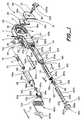
- FIG. 1illustrates an exploded perspective view of a first exemplary embodiment of a device according to the present invention
- FIG. 1 aillustrates a cross-sectional view of the device of FIG. 1;
- FIG. 2illustrates portions of a device in accordance with the present invention
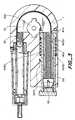
- FIG. 3illustrates a cross-sectional view of another embodiment in accordance with the present invention.
- FIG. 4illustrates an end elevational view of portions of the device of FIG. 3;
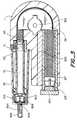
- FIG. 5illustrates a cross-sectional view of yet another embodiment in accordance with the present invention.
- FIG. 6illustrates a perspective view of yet another embodiment in accordance with the present invention.
- FIG. 7illustrates a cross-sectional view taken at line 7 — 7 in FIG. 6 .
- One advantage of capability of alternately using a catheter or a pen needleis unique to the invention because of the compact size, non-twisting attachment design and positive adjustment capability.
- the occurrence of infection and irritationis reduced because the medication, e.g., insulin does not continuously enter the subcutaneous site.
- the patientcan also use the device in a manner similar to currently available injection pens to delivery insulin when they do not want to use a catheter, thereby increasing the convenience of the device.
- bolus therapycatheter aided delivery, pen tip delivery, sanitary cartridge utilization, a reduction of injection site irritation, compact size, and the ability to select the method of delivery on a day-to-day basis, the patient is given many advantages by devices and methods of the present invention.
- a medication injection or delivery systemfor injecting fluids such as insulin within body tissue.
- the deviceincludes a housing, a flexible shaft movably mounted within the housing, and a dose setting, mechanism for controlling the movement of the shaft with respect to a fluid containing cartridge removably positioned within or mounted to the housing.
- the flexible shaftincludes a plunger and a flexible cable connected to the dose setting mechanism.
- the plunger and dose setting mechanismare connected together by the flexible shaft.
- the dose setting mechanismin one aspect of the invention, includes a screw, a locking mechanism, and a nut assembly connected to the flexible shaft.
- the dose setting mechanismis used to set the dosage and prime the catheter.
- the plungerretracts into a recess to permit a new cartridge to be installed quickly.
- the injection deviceincludes elements threadably engaging the nut assembly to adjust the dosage of medication.
- a spring axially connected to the dosage setting nutis positioned so as to move the dosage setting nut when the brake assembly releases the flexible shaft connected to the nut assembly and the plunger.
- the dosage setting nut assembly that is engaged to the screwis stopped when the bottom of the dosage setting nut assembly comes into contact with stops on the housing or case.
- the devicefurther includes elements for securing to the housing a cartridge containing fluid. The device alternatively does not have a spring connected with the dosage setting nut and the injection is accomplished by the patient manually providing pressure on the adjusting knob to inject the medication.
- the flexible shaftis constructed of materials that can transmit both tension and compression.
- the flexible shaftshould be capable of transmitting the forces around bends and curves, which insures that the device can be compact and discrete.
- the flexible shaftis capable of transmitting both tension and compression and also capable of being clamped by an external brake without the shaft being collapsed.
- the flexible shafttransmits the forces without axial deflection which would otherwise result in erroneous injection amounts.
- An outer springprovides compression resistance and an inner tube provides the ability for the spring neither to collapse when the brake is applied nor to distort when loaded axially in compression because it does not allow the windings to overlap each other when captivated in the guide tube.
- the cableprovides the tension resistance for the flexible shaft assembly.
- the present inventionwill utilize a standard insulin cartridge, holding 100-200 insulin units in a 1.5-3.0 milliliter volume, the present invention is not so limited, and can be resized and reconfigured to be used with medication cartridges or ampules of any size.
- the ability to provide a small, discreet injection device that is capable of being used with both a catheter and an injection needleprovides a significant advantage for the patient who must inject themselves on a regular basis, such as a person with diabetes.
- the patientcan configure the device with a catheter on those occasions where discreet injection is needed, such as at work or other public situations.
- the catheteris then inserted subcutaneously and the medication is injected by setting the dosage mechanism and releasing or manually injecting the dosage.
- the cathetercan be left in the patient for up to three days and thereby eliminates the need to insert a needle into themselves again over the three day period.
- Devices of the present inventioncan have a small size and compact shape, which can allow the patient to wear it or hide it in their clothes so that it is not obvious to the people around them.
- the alternate configuration of being used with a conventional pen tipprovides a means for the patient to use the same device to inject themselves when they do not want to use a catheter.
- the ability to use the device with two injection methodsis unique and made possible by the system use of bolus therapy and the small and compact size.
- the DCCTdetermined that the proper management of diabetes requires 4 or more injections of insulin per day.
- insulin-dependent diabeticsrarely observe this critical treatment therapy because of the difficult and indiscreet nature of the current insulin delivery methods.
- All the available device srequire the patient to carry the device and insulin, and inject in public.
- Those patients that use insulin pumpsare afforded a more discreet means of infusion, but because of the basal rate therapy, require that they test their glucose levels 7 to 10 times a day.
- the present inventiondoes not change the method of treatment but facilitates the delivery of insulin by providing a dual methodology to delivery the insulin that is selectable by the patient. They can either use a catheter or a pen-tip to deliver the required dosage of insulin.
- FIG. 1illustrates an exploded perspective view of a first exemplary embodiment of a device according to the present invention.
- the deviceincludes elements for holding a medication ampule 70 so that it can be connected to a medication delivery tube of the user's choice, a housing 1 including elements for transmitting force to the piston 71 of the ampule, and elements with which the user can select a dosage of medication for delivery from the device and manually or automatically initiate administration of the medication.
- One aspect of the present inventionis the provision of a force transmitting member which can effectively transmit force from dosage selection and manual administration elements along a non-linear path to the piston of the medication ampule, thus permitting the device as a whole to be constructed, and the constituent elements thereof arranged, in compact ways.
- the force transmitting membertransmits the force without axial deflection, which would otherwise reduce dosage accuracy.
- a sleeve 99includes a hollow interior sized to receive a medication ampule 70 therein through an opening 98 b in a cylindrical extension 98 of the sleeve.
- the sleeve 99preferably is transparent or translucent and preferably includes dosage indicia thereon so that the user may visually inspect the contents of the ampule vial and determine the amount of medication therein.
- the extension 98includes an upstanding, peg 98 a set back from the opening 98 b. The peg, 98 a cooperates with a circumferential groove 101 e formed on the interior of a slip collar 100 .
- the slip collarWhen the slip collar is slipped over the extension 98 with the peg 98 a extending through a longitudinal slot 101 d in the sidewall 101 a of the slip collar, the peg may enter the groove 101 e. With the peg in the circumferential groove, the slip collar 100 can be rotated, securing the slip collar to the extension 98 against longitudinal movement.
- a subcutaneous infusion set 800can be secured between the slip collar 100 and the extension 98 to fluidly communicate the interior of the medication ampule 70 with a subcutaneous needle 800 a on the distal end of the subcutaneous set 800 .
- the proximal end of the set 800includes a needle or other septum piercing element 815 with all associated hub 805 at the proximal end of the set.
- the hub 805has an outer diameter smaller than the interior diameter of the slip collar 100 , yet larger than the inner diameter of a distal opening 101 b of the slip collar, so that the slip collar will hold the hub and piercing element 815 in place.
- the piercing element 815has a length and diameter so that when the hub 805 and piercing element 815 are retained by the slip collar 100 within the hollow interior of the extension 98 , the piercing element pierces the septum 72 at the distal end of the medication ampule 70 .
- the slip collar 100 and extension 98secure the proximal end of the set 800 to the ampule 70 and place the subcutaneous needle 800 a in fluid communication with the interior of the ampule through the septum 72 .
- the hub 805applies a sufficient pressure to the septum 72 when engage to the septum to minimize deformation of the septum when the piston 71 is engaged.
- subcutaneous set 800instead of subcutaneous set 800 , the subcutaneous injection set described in Ser. No. 09/675,159, filed Sep. 29, 2000, entitled “Subcutaneous Injection Set for Use with a Reservoir that has a Septum”, Joel Douglas et al., which is incorporated by reference herein, can be used. Further optionally, the adapter described in Ser. No. 09/672,097, filed Sep. 29, 2000, entitled “Pen Needle Assembly and Adapter”, Joel Douglas et al, which is incorporated by reference herein, can be used. Also optionally, the adapter described in Ser. No. 09/672,456, filed Sep. 29, 2000, entitled “Micro Infusion Device”, Joel Douglas et al, which is incorporated by reference herein, can be used.
- An advantage of the present inventionis that, when used with an administration set which includes a length of tubing, such as tubing 800 b, between a piercing element and the needle (e.g., needle 800 a ) which is inserted into the user, the tubing can effectively act as a strain relief for the junction of the piercing, element 815 and the septum 72 , the junction of the needle 800 a and the user's skin, or both.
- the septum 72is less prone to be distorted by the piercing element 815 , and thus can increase the accuracy of the dosage administered and assist in maintaining the sterility of the contents of the medication ampule 70 .
- the user's skinis less prone to be pulled during injection, which can improve the user's comfort levels.
- the exemplary device illustrated in FIG. 1includes a housing 1 that has an interior cavity 5 that accommodates a flexible shaft 40 .
- the flexible shaft 40will be described in greater detail below and with reference to FIGS. 2 and 3.
- Flexible shaft 40is slidably movable in the cavity 5 so that it can extend out of the housing in order to push on the piston 71 of the ampule 70 . and in this manner acts as a plunger for the piston.
- the flexible shaftis constructed so that it is capable of transmitting force to the piston 71 to expel medication from the ampule 70 , but the flexible shaft is also flexible so that it can be used in a bent configuration.
- the provision of the flexible shafttherefore enables the design of the housing of devices according to the present invention to be more compact than traditional “pen-type” injectors, while allowing accurate injections to be made, because axial deformation of the flexible shaft is minimized.
- the housing 1includes openings 2 and 3 that lead to the cavity 5 .
- a fitting 130is positioned in the opening 2 , and includes a hollow interior 130 c, a cylindrical body 130 b, and an annular flange 130 a on one end of the fitting. As can be seen in FIG. 1, the hollow interior 130 c is sized so that the flexible shaft 40 can slide through the fitting 40 .
- the fittingis secured to the housing by, e.g., glue, ultrasonic welding, a screw 4 , or the like.
- a brake mechanism 25is also optionally provided to permit a user of the device to releasably hold the flexible shaft 40 from advancing into the ampule and dispensing medication.
- a seat 36is formed or positioned in the housing 1 , and includes a transverse hole 35 through the housing.
- a generally D-shaped brake shoe 26includes a threaded hole 26 a and a tubular extension 26 b which is received in the hole 35 with some clearance so that the extension can rotate in the hole.
- the housing 1includes a transverse openings 6 which can be closed by a cover 31 having a hole 31 a.
- a threaded bolt 27 with a head 29is threaded through the cover's hole 31 a and into the threaded hole 26 a.
- a cover 28is secured to the back side of the housing to cover the other side of hole 35 .
- a knob 300 having ears 300 ais secured to the head 29 to permit a user to rotate the bolt, and therefore the brake shoe 26 .
- the shoe 26is configured so that the upon rotation about an axis extending through hole 26 a and bolt 27 , the outer curved portion 26 c is rotated out farther away from the hole 26 a and engages and presses against the outer surface of the flexible shaft 40 . Further rotation of the shoe 26 causes the shoe to press against the flexible shaft 40 with a force sufficient to hold the shaft in place from displacement along the length of the shaft. Rotation of the shoe 26 , by rotation of the knob 300 , in the opposite direction disengages the curved portion 26 c from the flexible shaft 40 , permitting the shaft to move.
- the devicealso includes a set of elements which permit the user of the device to set a medication dosage and drive the flexible shaft 40 to dispense and administer that dosage.
- a set of elementswhich permit the user of the device to set a medication dosage and drive the flexible shaft 40 to dispense and administer that dosage.
- some portions of the flexible shaft 40have been removed from the illustration, but it is to be understood that the embodiment of the flexible shaft illustrated and described herein extends continuously between a plunger end attached to plunger 60 and another, opposite end secured to nut 95 .
- the nut 95includes partial threads 95 a on the top of the nut, and is connected to the flexible shaft 40 , e.g., by a swag 63 .
- the threads 95 ado not extend all the way around the nut, but rather are only present on a portion so that the nut call engage and disengage with a sleeve 105 , as described in greater detail below.
- the nuttherefore can include sidewalls 95 b which are sized and configured so as not to mate with the interior threaded surface 105 b of the sleeve 105 .
- the nut 95is attached to a tension cable 67 , which forms a part of the flexible shaft, described in greater detail below.
- the nut 95is positioned in the sleeve 105 and the sleeve can rotate around the nut when the threads of the nut and sleeve are engaged.
- the pitch of threads 95 ais selected so that a desired fraction or number of rotations of sleeve 105 relative to nut 95 corresponds to a desired dosage of medication dispensed from the ampule 70 .
- threads 95 acan be single or multistart threads.
- the sleeve 105includes, as discussed above, a hollow interior 105 c and has an interior surface which includes threads 105 b to mate with the exterior threads on nut 95 .
- the sleeve 105optionally further includes slits 152 , 153 through the wall of the sleeve.
- the slits 152 , 153define a tab or finger 112 which can flex away from the nut 95 , thus disengaging the threads of the sleeve 105 and the nut 95 . Deflection of the tab or finger 112 allows a user to push on plunger 60 to retract the nut 95 in sleeve 105 .
- the exterior surface of the sleeve 105also preferably includes one or more equally circumferentially spaced, longitudinally extending grooves 154 , 155 , 156 .
- the slits 152 , 153act as additional grooves and are preferably equally spaced with the grooves 154 , l 55 , 156 .
- additional groovesare provided in their places.
- the grooves and slitscooperate with one or more small pins or similar protuberances 151 to generate an audible click, a tactile snap, or both, when the sleeve 105 is rotated within the housing 1 .
- the number and spacing of the grooves 154 , 1 55 156is selected along with the pitch of the threads 95 a, 105 b so that the circumferential distance between the grooves corresponds to a known portion of a desired dosage.
- threads 95 a, 105 b and the circumferential spacing of grooves 154 , 155 , 156can be selected together so that one unit of medication from ampule 70 is dispensed for each audible/tactile click generated by the interaction of pins 151 and the grooves.
- a dosage knob or dial 150is secured to the outer end 105 a of the sleeve 105 so that rotation of the knob 150 rotates the sleeve.
- the knob 150When assembled (see, e.g., FIG. 3 ), the knob 150 is outside of the housing 1 , while the sleeve 105 moves in and out of the cavity 5 through the opening 3 .
- a motion limiting element 120is positioned in the sleeve 105 and partially around the nut 95 .
- the motion limiting elementtakes the form of a split shaft having a longitudinally extending slot 120 a that extends transversely through the shaft.
- the slot 120 acan be, for ease of assembly, open at the end 120 b of the shaft.
- the transverse width of the shaft 120is selected to be smaller than the internal diameter of the sleeve 105 in which the shall is positioned so as not to interfere with the rotation of the sleeve relative to the nut 95 .
- the dimensions of the slot 120 aare selected so that the nut 95 , as well as the flexible shaft 40 secured to the nut 95 , can move longitudinally along the shaft without the shaft interfering with this movement.
- the length of the slot 120 ais selected, however, so that the closed end 120 c of the slot 120 prevents the nut 95 from being, backed out of the sleeve 105 . Further preferably, the length of the slot 120 a is selected to correspond to the maximum dosage amount that it is desired to dispense from ampule 70 .
- the length of the slot 120 acan be selected to be a preselected percentage of the total distance that piston 71 can travel in ampule 70 up to 100% of the travel distance.
- the length of the flexible shaft 40is selected so that the nut 95 is positioned adjacent to the closed end 120 c when a new ampule is installed in the device.
- a second retaining sleeve 107is also positioned in the cavity 5 .
- the sleeve 107is mounted in the housing 1 so that an open outer end 107 c of the sleeve is adjacent to the opening 3 .
- the sleeve 107includes a hollow interior 107 a.
- the inner end of the sleeve 107includes an opening through which the flexible shaft 40 extends which is delimited by a stop 107 b.
- An insert 160is mounted in the stop 107 b.
- the insert 160includes flats 160 a which are sized to receive the end 120 b of the shaft 120 , and the shaft is secured to the insert.
- the insertalso includes a hollow interior 160 b through which the flexible shaft 40 extends.
- the housing 1can further include a recess 202 adjoining that portion of the cavity 5 which contains the sleeve 107 .
- a cylindrical locking member 200is rotatably positioned in the recess 202 .
- the member 200includes a flat exterior portion 201 a, a cylindrical exterior portion 201 b, and a keyhole, recess, or the like 201 in the external face of the member.
- the sleeve 107in this additional embodiment, includes a cutout portion 107 d on that portion of the sleeve which faces the recess 202 .
- Recess 202 . member 200 , and cutout portion 107 aare provided to cooperate with tab 12 , as described in greater detail below, to permit rapid retraction of the flexible cable 40 and nut 95 .
- the flexible shaft 40includes an outer flexible spring 3000 , an intermediate flexible tube 3010 positioned inside the spring 3000 , and an inner tension cable 3020 positioned inside the tube 3010 .
- the outer diameter of the intermediate tube 3010is preferably selected to be slightly smaller than the inner diameter of the spring 3000 so that the tube supports the spring along its entire length, while permitting the spring, and tube together to bend without kinking.
- the tube 3010also prevents the spring windings from overlapping one another.
- the inner tension cable 3020which corresponds to element 67 in FIG. 1, extends between the plunger 60 and the nut 95 .
- the cable 3020is secured to the plunger 60 , such as by screw 64 , and to nut 95 , as by the swag 63 .
- the tension cable 3020through the plunger 60 and the nut 95 . prevents the spring 3000 from extending, yet is flexible to also bend and flex with the spring and the tube 3010 to transmit force along a linear or nonlinear path to the piston 71 of the ampule 70 without axial deformation.
- the flexible shaft 40includes a spring segment available from Century Spring of Los Angeles, Calif., model E-12, which has a wire size of at least 0.035 and an outer diameter winding width of 0.25 inches.
- the intermediate tubecan be formed of a PVC tube with an outer diameter of 0.176 inches and inner diameter of 0.100 inches.
- a stainless steel cable of 0.035 inches outer diameteris threaded through the PVC tube and used to place the assembly under compression.
- FIG. 5illustrates the device and an ampule 70 positioned therein prior to the administration of medication from the ampule, and with the flexible shaft 40 completely retracted.
- the userlocks the flexible shaft 40 by rotating the knob 300 .
- the userthan rotates the knob 150 , which rotates the sleeve 105 .
- Audible and/or tactile clicksare produced by rotation of the sleeve relative to the housing 1 .
- the sleeve 105moves out of the housing 1 while the nut 95 remains stationary. In this manner, the sleeve is backed out of the housing a distance which relates to, and is preferably the same as, the distance that the piston 71 will be moved.
- the userWhen the user has backed out the sleeve 105 the desired amount, as preferably indicated by the audible and/or tactile clicks, or by visual inspection, the user turns the knob 300 to unlock the flexible shaft 40 and to permit it to move. The user then presses on the flat face 150 a of the knob, which pushed the sleeve 105 in toward the housing. Because the threads 105 b of the sleeve 105 mate with the threads 95 a of the nut 95 , and the nut is secured to the flexible shaft 40 , the nut 95 is driven along with the sleeve toward the housing. This movement of the nut 95 and sleeve 105 continues while the user presses on the face 150 a.
- the flexible shaft 40pushed by the nut 95 through the cavity 5 and through the fitting 130 .
- the plunger 60 on the plunger end of the flexible shaft 40pushes against the piston 71 of the ampule 70 , which in turn expels medication from the ampule.
- the ampule 70is held in the device by split collar 100 , and therefore the force generated by the user against face 150 a is transmitted through the sleeve 105 , nut 95 , flexible shaft 40 , and plunger 60 to the piston 71 .
- the flexible shaft 40is free to move along its own length in the cavity 5 . but restrained from buckling by the housing 1 , the direction of the user-generated force is changed but still transmitted to the piston.
- the knob 150is again adjacent to the housing 1 , as illustrated in FIG. 5 .
- the entire devicecan then conveniently be placed in a carrying case, handbag, pocket. or wherever the user desires, while permitting the subcutaneous set 800 to remain in place inconspicuously attached to the infusion device.
- the plunger 60When the user desires to administer another volume of medication from the ampule 70 , the plunger 60 is still in position against the piston 71 from the previous administration.
- the nut 95is in a position between the end 120 c and the end 120 b of the shaft 120 , having been moved as a result of the prior advancement of the flexible shaft 40 .
- the knob 150is again rotated, backing out the sleeve 105 , and the flexible shaft 40 is again advanced through the housing 1 to push the piston 71 .
- Devices according to the present inventionfunction to preserve the information of how much of the medication a user desires to dispense from the ampule, even when there less than this amount contained in the ampule installed in the device. That is, devices according to the present invention have a memory aspect which retains information about how much of a dosage is left to be administered even if the ampule must be changed to complete the administration.
- the sleeve 105 and flexible shaft 40will only travel the distance to dispense the 7 units.
- knob 150will not be moved up to housing 1 , and the user will have an indication that the entire desired dosage has not been administered.
- the usercan see how much additional medication must be administered for a complete dosage. The user can load a new ampule into the device, dial out an appropriate supplemental dosage amount, and complete the dosage administration.
- the shaftWhen the flexible shaft 40 has been moved so that the nut 95 is against the insert 160 , the shaft must be retracted to reset the device. This can be accomplished several ways.
- the knob 150can be retracted fully, pulling the nut with it, and then the knob 150 rotated to advance the sleeve 105 into the housing while the nut 95 remains stationary.
- the provision of locking member 200 , recess 202 , and cutout 107 dpermits another way of resetting the device.
- a tool 113is provided which includes an end which can be inserted into recess 201 a to rotate the locking member 200 in the recess 202 .
- the knob 150is pulled out as far as it will, which retracts the nut 95 and the flexible shaft 40 .
- the knob 150is then rotated so that an indicator, such as flat 150 b opposite and aligned with slot 120 a, shows that the tab 112 is adjacent to and aligned with the cutout 107 d and recess 202 .
- the tool 113is then used to rotate the locking member 200 in recess 202 so that the flat 201 a is aligned with and adjacent to the tab 112 .
- the tabis no longer restrained against radial movement, and can deflect outward in response to relative movement of the nut 95 .
- the knob 150is then pushed in, which causes the sleeve 105 to move in toward the housing.
- the tab 112is aligned with the cutout 107 a and the flat 201 a, the tab can deflect outward, disengaging the threads 105 b from the threads 95 a of the nut 95 .
- the sleeve 105therefore moves inward relative to the nut 95 , with the result that the nut moves to a position closer to end 105 a of the sleeve. If the nut 95 is not yet adjacent to the end 105 a, this process can be repeated to move the sleeve 105 and nut 95 relative to each other to reset the device.
- FIGS. 3 and 4illustrate yet another embodiment in accordance with the present invention.
- the device illustrated in FIGS. 3 and 4is similar in some respects to those illustrated in FIGS. 1-2, and therefore only the differences between them will be described herein.
- the embodiment of FIGS. 3 and 4include structures which provide an automatic injection function.
- the housing 1includes the cavity 5 having an additional space 4000 radially outside the space in which the sleeve 105 extends.
- the sleeve 105includes an annular shoulder 4110 which slides in the space 4000 .
- a spring 4080is also positioned in the space 4000 between the shoulder 4110 and a shoulder 4090 of the housing which delimits the space.
- FIG. 4illustrates an end view of the shoulder 4110 .
- the sleeve 105includes portions 4010 which act as spring cams against the inner surface 4100 of that portion of the housing which defines the space 4000 .
- frictionis developed between the housing and the shoulder 4110 .
- the profile of the surface 4100is slightly tapered so that the frictional force between the shoulder and the surface chances.
- the device illustrated in FIGS. 3 and 4is used in a manner very similar to that described above with respect to FIGS. 1-2
- the spring, 4080is compressed, and exerts a force in the direction of arrow 4070 against the sleeve 105 through the shoulder 4110 .
- the knob 300is rotated, unlocking the flexible shaft 40 .
- the spring 4080pushes against the shoulder 4110 , driving the sleeve 105 , nut 95 , and flexible shaft 40 as described above.
- the friction between the shoulder 4110 and the surface 4100which acts against the motion of the sleeve in the direction opposite the arrow 4070 , slows the sleeve 105 .
- the taper of the surface 4100 and the elasticity of the spring cams 4010generated by the normal force 4020 of the spring cams against the surface 4100 , cause the frictional force to change over the travel of the shoulder 4110 , thus regulating the speed of the injection.
- the surface 4100is tapered so that the frictional force is higher at the beginning of the injection stroke and less toward the end of the injection stroke.
- FIG. 5illustrates other aspects of the present invention, and portions of the elements illustrated in FIG. 5 have been described elsewhere herein.
- FIG. 5also illustrates another embodiment of a device for administering the dosage to the user, a pen needle 900 .
- Pen needles usable in the present inventionare currently commercially available, for example a Novofine® 301 ⁇ 3 inch (8 mm) pen needle (Novo Nordisk, Princeton, N.J.).
- the pen needle 900includes a needle 902 for piercing the septum 72 , a needle 904 for insertion subcutaneously into the patient in fluid communication with the needle 902 , and a cylindrical shroud or cover 906 which covers the needle 902 .
- the shroud 906is placed over the septum 72 , which pushes the tip of the needle 902 into the interior of the ampule 70 .
- the split collar 100is placed over the pen needle 900 , securing it in place.
- a cap or cover 908 covering the needle 904is then removed, the needle inserted into the user, and the dosage can be delivered to the user.
- FIG. 6illustrates yet another embodiment of a device in accordance with the present invention.
- the device illustrated in FIG. 6is similar in some respects to other embodiments described herein.
- the deviceincludes a mechanism 700 which permit the user of the device to establish a zero set point on a scale, so that the user can then set a proper dosage amount for administration.
- a sleeve 705is mounted around the outer end of the sleeve 105 (see FIG. 1) and includes a set of numbers printed on the external surface of the sleeve 705 .
- the sleeve 705includes an outer ring 708 which is adjacent to a ring 704 on the dosage setting knob 703 (which corresponds to knob 150 ) of the sleeve 105 .
- the rings 704 and 708include mating structures. Such as complementary teeth, so that when the rings are held together, they will rotate together without slipping.
- a spring 702is positioned between the rings 704 and 708 to bias the outer sleeve 705 outward so that the rings abut each other.
- the outer sleeveextends into the housing 1 through which, with the aid of a magnifying glass type window 706 , the user can view the numbers printed oil the exterior of the sleeve 705 .
- the spacing of the numbers on the sleeve 705is selected so that a relatively large annular rotation 701 of the dosage setting knob 703 is matched with the appropriate distance of linear motion 707 of the sleeves 705 . 105 .
- the userpushes the outer sleeve 705 in toward the housing against the force of the spring 702 . disengaging, the complementary structures on the rings 704 , 708 .
- the outer sleeve 705can then be freely rotated until a zero appears in window 706 .
- the userthen releases the sleeve, which returns to its position with the rings 704 , 708 next to each other.
- the usercan then manipulate the dosage knob 703 to back out sleeve 105 , which carries with it sleeve 705 because of the engagement of rings 704 and 708 . Therefore, the outer sleeve 705 is rotated and moved further out of the housing 1 , moving the appropriate number printed on the exterior of sleeve 705 beneath window 706 for the user to verify that the dosage knob has been set to administer the correct dosage.
- FIGS. 6 and 7illustrate yet a further embodiment of the present invention.
- a side injection actuator 600is movably mounted to the side of the housing 1 , and is connected (see FIG. 7) to portions of the sleeve 105 .
- the actuator 600includes a scale indicator 603 which aligns with a scale 601 printed on the exterior of the housing.
- FIG. 7, which illustrates a partial cross sectional view through the housing at line 7 — 7the housing includes a slot 607 in which a connecting arm 613 slides.
- the arm 613connects together the actuator 600 and a ring 611 which is received in the same space as the spring 609 (corresponding to spring 4080 ).
- spring 609 and the automatic injection featurecan be optionally removed.
- the ring 611abuts against an outwardly extending shoulder 605 , similar to shoulder 4110 , formed on sleeve 105 .
- the side injection actuator 600moves alone with sleeve 105 as the sleeve is backed out of the housing 1 when the user sets a dosage amount with dosage knob 150 or 703 , because the ring, 611 is pushed linearly backward by the shoulder 605 . As the ring 611 and shoulder 605 are not attached, however, the rotation of shoulder 605 as the sleeve 105 is backed out does not cause the ring 611 to rotate.
- the usercan choose between pushing on the dosage knob 150 or 703 , or pushing the side injection actuator forward along the housing toward the position illustrated in FIG. 7 .
- the scale 601 and scale indicator 603provide a visual check for the user that the dosage amount has correctly been set.
Landscapes
- Health & Medical Sciences (AREA)
- Vascular Medicine (AREA)
- Engineering & Computer Science (AREA)
- Anesthesiology (AREA)
- Biomedical Technology (AREA)
- Heart & Thoracic Surgery (AREA)
- Hematology (AREA)
- Life Sciences & Earth Sciences (AREA)
- Animal Behavior & Ethology (AREA)
- General Health & Medical Sciences (AREA)
- Public Health (AREA)
- Veterinary Medicine (AREA)
- Infusion, Injection, And Reservoir Apparatuses (AREA)
Abstract
Description
Claims (27)
Priority Applications (3)
| Application Number | Priority Date | Filing Date | Title |
|---|---|---|---|
| US09/672,103US6482186B1 (en) | 1999-09-29 | 2000-09-29 | Reusable medication delivery device |
| US09/845,256US6659982B2 (en) | 2000-05-08 | 2001-05-01 | Micro infusion drug delivery device |
| US10/176,662US6641566B2 (en) | 1999-09-29 | 2002-06-24 | Reusable medication delivery device |
Applications Claiming Priority (4)
| Application Number | Priority Date | Filing Date | Title |
|---|---|---|---|
| US15653599P | 1999-09-29 | 1999-09-29 | |
| US17057099P | 1999-12-13 | 1999-12-13 | |
| US17776200P | 2000-01-24 | 2000-01-24 | |
| US09/672,103US6482186B1 (en) | 1999-09-29 | 2000-09-29 | Reusable medication delivery device |
Related Parent Applications (1)
| Application Number | Title | Priority Date | Filing Date |
|---|---|---|---|
| US09/672,456Continuation-In-PartUS6629949B1 (en) | 2000-05-08 | 2000-09-29 | Micro infusion drug delivery device |
Related Child Applications (2)
| Application Number | Title | Priority Date | Filing Date |
|---|---|---|---|
| US09/845,256Continuation-In-PartUS6659982B2 (en) | 2000-05-08 | 2001-05-01 | Micro infusion drug delivery device |
| US10/176,662ContinuationUS6641566B2 (en) | 1999-09-29 | 2002-06-24 | Reusable medication delivery device |
Publications (1)
| Publication Number | Publication Date |
|---|---|
| US6482186B1true US6482186B1 (en) | 2002-11-19 |
Family
ID=27387885
Family Applications (2)
| Application Number | Title | Priority Date | Filing Date |
|---|---|---|---|
| US09/672,103Expired - Fee RelatedUS6482186B1 (en) | 1999-09-29 | 2000-09-29 | Reusable medication delivery device |
| US10/176,662Expired - Fee RelatedUS6641566B2 (en) | 1999-09-29 | 2002-06-24 | Reusable medication delivery device |
Family Applications After (1)
| Application Number | Title | Priority Date | Filing Date |
|---|---|---|---|
| US10/176,662Expired - Fee RelatedUS6641566B2 (en) | 1999-09-29 | 2002-06-24 | Reusable medication delivery device |
Country Status (5)
| Country | Link |
|---|---|
| US (2) | US6482186B1 (en) |
| JP (1) | JP2003510135A (en) |
| AU (1) | AU7839900A (en) |
| DE (2) | DE10048220A1 (en) |
| IE (1) | IE20000785A1 (en) |
Cited By (62)
| Publication number | Priority date | Publication date | Assignee | Title |
|---|---|---|---|---|
| US20040054326A1 (en)* | 2002-08-30 | 2004-03-18 | Edgar Hommann | Device for controlled delivery of an injectable liquid |
| US20040122368A1 (en)* | 2001-03-27 | 2004-06-24 | Langley Christopher Nigel | Injection device |
| US20050020986A1 (en)* | 2002-06-17 | 2005-01-27 | Mickley Timothy J. | Catheter device and method for delivering a dose internally during minimally-invasive surgery |
| US20060116660A1 (en)* | 2004-04-30 | 2006-06-01 | Impact Medical Technologies, Llc | Medical hub having transparent observation section |
| US20060186143A1 (en)* | 2005-02-24 | 2006-08-24 | Boston Scientific Santa Rosa Corporation | Constant force material delivery system and method |
| US20070005125A1 (en)* | 2002-04-10 | 2007-01-04 | Boston Scientific Scimed, Inc. | Hybrid stent |
| US20070224877A1 (en)* | 2005-03-18 | 2007-09-27 | Bissell Homecare, Inc. | Strain relief asssembly |
| WO2008017330A1 (en)* | 2006-08-10 | 2008-02-14 | Henkel Ag & Co. Kgaa | Cartridge gun |
| GB2443390A (en)* | 2006-11-03 | 2008-05-07 | Owen Mumford Ltd | Medicine delivery apparatus |
| USD575394S1 (en)* | 2006-11-21 | 2008-08-19 | It Pharma Llp | Syringe insert |
| US20090299299A1 (en)* | 2001-01-05 | 2009-12-03 | Lynch George R | Low profile pivoting joint infusion assembly |
| US20100292653A1 (en)* | 2007-09-25 | 2010-11-18 | Becton Dickinson France S.A.S. | Autoinjector with trigger positionable in active position by movement of a safety shield and indication of the active position |
| US20100324494A1 (en)* | 2009-06-01 | 2010-12-23 | Sanofi-Aventis Deutschland Gmbh | Drug delivery device last dose lock-out mechanism |
| US20100324487A1 (en)* | 2001-06-29 | 2010-12-23 | Lynch George R | Low profile, pivotal connection infusion assembly |
| WO2011067270A1 (en)* | 2009-12-02 | 2011-06-09 | Sanofi-Aventis Deutschland Gmbh | Drive mechanism for drug delivery devices |
| WO2011075042A1 (en)* | 2009-12-14 | 2011-06-23 | Shl Group Ab | Medicament delivery device |
| US20110190704A1 (en)* | 2005-09-21 | 2011-08-04 | Lynch George R | One piece sealing reservoir for an insulin infusion pump |
| US8287495B2 (en) | 2009-07-30 | 2012-10-16 | Tandem Diabetes Care, Inc. | Infusion pump system with disposable cartridge having pressure venting and pressure feedback |
| US8333717B1 (en) | 2011-06-21 | 2012-12-18 | Yofimeter, Llc | Test unit cartridge for analyte testing device |
| US8408421B2 (en) | 2008-09-16 | 2013-04-02 | Tandem Diabetes Care, Inc. | Flow regulating stopcocks and related methods |
| US8430849B2 (en) | 2010-09-24 | 2013-04-30 | Perqflo, Llc | Infusion pumps and plunger pusher position-responsive cartridge lock for infusion pumps |
| US8573027B2 (en) | 2009-02-27 | 2013-11-05 | Tandem Diabetes Care, Inc. | Methods and devices for determination of flow reservoir volume |
| US8603034B2 (en) | 2005-07-12 | 2013-12-10 | Applied Diabetes Research, Inc. | One piece sealing reservoir for an insulin infusion pump |
| US8650937B2 (en) | 2008-09-19 | 2014-02-18 | Tandem Diabetes Care, Inc. | Solute concentration measurement device and related methods |
| US20140148783A1 (en)* | 2004-11-22 | 2014-05-29 | Intelliject, Inc. | Devices, systems and methods for medicament delivery |
| US8905972B2 (en) | 2010-11-20 | 2014-12-09 | Perqflo, Llc | Infusion pumps |
| US8911408B2 (en) | 2001-01-05 | 2014-12-16 | Applied Diabetes Research, Inc. | Pivoting joint infusion system with seal |
| WO2014153447A3 (en)* | 2013-03-22 | 2014-12-18 | 3M Innovative Properties Company | Microneedle applicator comprising a counter assembly |
| US8915879B2 (en) | 2010-09-24 | 2014-12-23 | Perqflo, Llc | Infusion pumps |
| US8961432B2 (en) | 2011-06-21 | 2015-02-24 | Yofimeter, Llc | Analyte testing devices |
| US8986253B2 (en) | 2008-01-25 | 2015-03-24 | Tandem Diabetes Care, Inc. | Two chamber pumps and related methods |
| US9022988B1 (en) | 2010-05-07 | 2015-05-05 | Kavan J. Shaban | System and method for controlling a self-injector device |
| US9056170B2 (en) | 2004-11-22 | 2015-06-16 | Kaleo, Inc. | Devices, systems and methods for medicament delivery |
| US9084849B2 (en) | 2011-01-26 | 2015-07-21 | Kaleo, Inc. | Medicament delivery devices for administration of a medicament within a prefilled syringe |
| US9149579B2 (en) | 2004-11-22 | 2015-10-06 | Kaleo, Inc. | Devices, systems and methods for medicament delivery |
| US9216249B2 (en) | 2010-09-24 | 2015-12-22 | Perqflo, Llc | Infusion pumps |
| US9250106B2 (en) | 2009-02-27 | 2016-02-02 | Tandem Diabetes Care, Inc. | Methods and devices for determination of flow reservoir volume |
| US9498573B2 (en) | 2010-09-24 | 2016-11-22 | Perqflo, Llc | Infusion pumps |
| US9517307B2 (en) | 2014-07-18 | 2016-12-13 | Kaleo, Inc. | Devices and methods for delivering opioid antagonists including formulations for naloxone |
| US9522235B2 (en) | 2012-05-22 | 2016-12-20 | Kaleo, Inc. | Devices and methods for delivering medicaments from a multi-chamber container |
| CN107027294A (en)* | 2014-12-08 | 2017-08-08 | 赛诺菲 | Clicker acoustical generator assembly and the delivery device with the clicker acoustical generator assembly |
| US9962486B2 (en) | 2013-03-14 | 2018-05-08 | Tandem Diabetes Care, Inc. | System and method for detecting occlusions in an infusion pump |
| US9993595B2 (en) | 2015-05-18 | 2018-06-12 | Tandem Diabetes Care, Inc. | Patch pump cartridge attachment |
| US10071203B2 (en) | 2004-11-22 | 2018-09-11 | Kaleo, Inc. | Devices, systems and methods for medicament delivery |
| US10159786B2 (en) | 2014-09-30 | 2018-12-25 | Perqflo, Llc | Hybrid ambulatory infusion pumps |
| US10258736B2 (en) | 2012-05-17 | 2019-04-16 | Tandem Diabetes Care, Inc. | Systems including vial adapter for fluid transfer |
| US10350349B2 (en) | 2014-05-20 | 2019-07-16 | Cequr Sa | Medicine delivery device with restricted access filling port |
| WO2019143753A1 (en)* | 2018-01-17 | 2019-07-25 | Amgen Inc. | Drug delivery mechanism |
| US10576206B2 (en) | 2015-06-30 | 2020-03-03 | Kaleo, Inc. | Auto-injectors for administration of a medicament within a prefilled syringe |
| US10688244B2 (en) | 2016-12-23 | 2020-06-23 | Kaleo, Inc. | Medicament delivery device and methods for delivering drugs to infants and children |
| US10695495B2 (en) | 2015-03-24 | 2020-06-30 | Kaleo, Inc. | Devices and methods for delivering a lyophilized medicament |
| US10737028B2 (en) | 2004-11-22 | 2020-08-11 | Kaleo, Inc. | Devices, systems and methods for medicament delivery |
| US10850036B2 (en) | 2015-08-27 | 2020-12-01 | E3D Agricultural Cooperative Association | Reusable automatic injection device |
| US11071849B2 (en) | 2015-08-18 | 2021-07-27 | B. Braun Melsungen Ag | Catheter devices with valves and related methods |
| US11167087B2 (en) | 2019-08-09 | 2021-11-09 | Kaleo, Inc. | Devices and methods for delivery of substances within a prefilled syringe |
| US11590286B2 (en) | 2004-11-22 | 2023-02-28 | Kaleo, Inc. | Devices, systems and methods for medicament delivery |
| US11672909B2 (en) | 2016-02-12 | 2023-06-13 | Medtronic Minimed, Inc. | Ambulatory infusion pumps and assemblies for use with same |
| US11684712B2 (en) | 2015-02-18 | 2023-06-27 | Medtronic Minimed, Inc. | Ambulatory infusion pumps and reservoir assemblies for use with same |
| US11850377B2 (en) | 2018-12-17 | 2023-12-26 | B. Braun Melsungen Ag | Catheter assemblies and related methods |
| US11865306B2 (en) | 2014-02-10 | 2024-01-09 | E3D A.C.A.L Ltd | Semi disposable auto injector |
| US12178992B2 (en) | 2014-09-30 | 2024-12-31 | Medtronic Minimed, Inc. | Different disposable assemblies for the same reusable assembly |
| US12268847B1 (en) | 2021-02-10 | 2025-04-08 | Kaleo, Inc. | Devices and methods for delivery of substances within a medicament container |
Families Citing this family (93)
| Publication number | Priority date | Publication date | Assignee | Title |
|---|---|---|---|---|
| IL156245A0 (en) | 2000-12-22 | 2004-01-04 | Dca Design Int Ltd | Drive mechanism for an injection device |
| US7544188B2 (en) | 2001-07-19 | 2009-06-09 | Intelliject, Inc. | Medical injector |
| US7338465B2 (en)* | 2002-07-02 | 2008-03-04 | Patton Medical Devices, Lp | Infusion device and method thereof |
| DE20317377U1 (en)* | 2003-11-03 | 2005-03-17 | B D Medico S A R L | injection device |
| US8029454B2 (en) | 2003-11-05 | 2011-10-04 | Baxter International Inc. | High convection home hemodialysis/hemofiltration and sorbent system |
| ES2385140T3 (en)* | 2004-02-18 | 2012-07-18 | Ares Trading S.A. | Portable electronic injection device for injecting liquid medications |
| US7172578B2 (en)* | 2004-04-15 | 2007-02-06 | Alcon, Inc. | Sterile tubing sheath |
| US7648482B2 (en) | 2004-11-22 | 2010-01-19 | Intelliject, Inc. | Devices, systems, and methods for medicament delivery |
| US8361026B2 (en) | 2005-02-01 | 2013-01-29 | Intelliject, Inc. | Apparatus and methods for self-administration of vaccines and other medicaments |
| US8206360B2 (en) | 2005-02-01 | 2012-06-26 | Intelliject, Inc. | Devices, systems and methods for medicament delivery |
| US9022980B2 (en) | 2005-02-01 | 2015-05-05 | Kaleo, Inc. | Medical injector simulation device |
| US7731686B2 (en) | 2005-02-01 | 2010-06-08 | Intelliject, Inc. | Devices, systems and methods for medicament delivery |
| US8231573B2 (en) | 2005-02-01 | 2012-07-31 | Intelliject, Inc. | Medicament delivery device having an electronic circuit system |
| EP1690559A1 (en)* | 2005-02-14 | 2006-08-16 | Ares Trading S.A. | Medication delivery device |
| EP1690560A1 (en)* | 2005-02-14 | 2006-08-16 | Ares Trading S.A. | Medication delivery device |
| US8512288B2 (en)* | 2006-08-23 | 2013-08-20 | Medtronic Minimed, Inc. | Infusion medium delivery device and method with drive device for driving plunger in reservoir |
| US8277415B2 (en) | 2006-08-23 | 2012-10-02 | Medtronic Minimed, Inc. | Infusion medium delivery device and method with drive device for driving plunger in reservoir |
| US7905868B2 (en) | 2006-08-23 | 2011-03-15 | Medtronic Minimed, Inc. | Infusion medium delivery device and method with drive device for driving plunger in reservoir |
| EP1754498A1 (en) | 2005-08-19 | 2007-02-21 | Roche Diagnostics GmbH | Driving device for an injection or infusion device |
| EP1940491B1 (en) | 2005-08-22 | 2021-10-27 | Medtronic Minimed, Inc. | Fluid delivery device |
| US8105279B2 (en) | 2005-09-26 | 2012-01-31 | M2 Group Holdings, Inc. | Dispensing fluid from an infusion pump system |
| CN101389366B (en) | 2005-11-03 | 2012-12-26 | 巴顿医疗设备有限公司 | Fluid delivery devices and system |
| US8114064B2 (en)* | 2006-03-16 | 2012-02-14 | Calibra Medical, Inc. | Infusion device with piston pump |
| EP2125075A2 (en) | 2007-01-22 | 2009-12-02 | Intelliject, Inc. | Medical injector with compliance tracking and monitoring |
| EP1961436B1 (en) | 2007-02-24 | 2016-08-24 | Roche Diabetes Care GmbH | Infusion system |
| US8434528B2 (en) | 2007-04-30 | 2013-05-07 | Medtronic Minimed, Inc. | Systems and methods for reservoir filling |
| US8613725B2 (en) | 2007-04-30 | 2013-12-24 | Medtronic Minimed, Inc. | Reservoir systems and methods |
| US7963954B2 (en) | 2007-04-30 | 2011-06-21 | Medtronic Minimed, Inc. | Automated filling systems and methods |
| JP5102350B2 (en) | 2007-04-30 | 2012-12-19 | メドトロニック ミニメド インコーポレイテッド | Reservoir filling / bubble management / infusion medium delivery system and method using the system |
| US8323250B2 (en) | 2007-04-30 | 2012-12-04 | Medtronic Minimed, Inc. | Adhesive patch systems and methods |
| US7959715B2 (en) | 2007-04-30 | 2011-06-14 | Medtronic Minimed, Inc. | Systems and methods allowing for reservoir air bubble management |
| US8597243B2 (en) | 2007-04-30 | 2013-12-03 | Medtronic Minimed, Inc. | Systems and methods allowing for reservoir air bubble management |
| NZ556142A (en)* | 2007-06-25 | 2009-11-27 | Novartis Ag | Animal remedy dispensing means |
| BRPI0817907B8 (en) | 2007-10-02 | 2021-06-22 | Lamodel Ltd | apparatus for administering a substance to an individual |
| US9656019B2 (en) | 2007-10-02 | 2017-05-23 | Medimop Medical Projects Ltd. | Apparatuses for securing components of a drug delivery system during transport and methods of using same |
| US10420880B2 (en) | 2007-10-02 | 2019-09-24 | West Pharma. Services IL, Ltd. | Key for securing components of a drug delivery system during assembly and/or transport and methods of using same |
| USD994111S1 (en) | 2008-05-12 | 2023-08-01 | Kaleo, Inc. | Medicament delivery device cover |
| CA3070618C (en) | 2008-05-20 | 2021-07-20 | Avant Medical Corp. | Autoinjector system |
| US8052645B2 (en) | 2008-07-23 | 2011-11-08 | Avant Medical Corp. | System and method for an injection using a syringe needle |
| DK2376149T3 (en)* | 2008-12-12 | 2014-11-24 | Shl Group Ab | Drug delivery device |
| DK2355872T3 (en) | 2008-12-12 | 2016-02-22 | Shl Group Ab | Drug delivery device |
| US8353864B2 (en) | 2009-02-18 | 2013-01-15 | Davis David L | Low cost disposable infusion pump |
| US8197235B2 (en) | 2009-02-18 | 2012-06-12 | Davis David L | Infusion pump with integrated permanent magnet |
| US9101706B2 (en)* | 2009-10-13 | 2015-08-11 | Valeritas, Inc. | Fluid delivery device |
| TWI415644B (en)* | 2009-12-14 | 2013-11-21 | Shl Group Ab | Medicament delivery device |
| US9211378B2 (en) | 2010-10-22 | 2015-12-15 | Cequr Sa | Methods and systems for dosing a medicament |
| US8627816B2 (en) | 2011-02-28 | 2014-01-14 | Intelliject, Inc. | Medicament delivery device for administration of opioid antagonists including formulations for naloxone |
| US8939943B2 (en) | 2011-01-26 | 2015-01-27 | Kaleo, Inc. | Medicament delivery device for administration of opioid antagonists including formulations for naloxone |
| PL2699293T3 (en) | 2011-04-20 | 2019-08-30 | Amgen Inc. | Autoinjector apparatus |
| US9289556B2 (en) | 2011-09-30 | 2016-03-22 | Becton Dickinson France, S.A.S. | Syringe with plunger rod having a flexible portion |
| USD693455S1 (en) | 2011-11-08 | 2013-11-12 | Becton, Dickinson And Company | Microinfuser |
| USD692997S1 (en) | 2011-11-08 | 2013-11-05 | Becton Dickinson France, S.A.S. | Microinfuser |
| USD692552S1 (en) | 2011-11-08 | 2013-10-29 | Becton Dickinson France, S.A.S. | Microinfuser |
| CN104023785B (en) | 2011-11-22 | 2017-03-01 | 贝克顿·迪金森公司 | Drug delivery system with delay mechanism |
| JP6039190B2 (en)* | 2012-02-13 | 2016-12-07 | 株式会社ニデック | Medical instruments |
| USD898908S1 (en) | 2012-04-20 | 2020-10-13 | Amgen Inc. | Pharmaceutical product cassette for an injection device |
| CA2808738C (en)* | 2012-09-26 | 2014-03-18 | Gadlight, Inc | Portable medicine injection device and metering system |
| GB2526948A (en) | 2012-12-27 | 2015-12-09 | Kaleo Inc | Systems for locating and interacting with medicament delivery devices |
| CA2904661C (en) | 2013-03-15 | 2022-03-15 | Amgen Inc. | Drug cassette, autoinjector, and autoinjector system |
| BR112015024053A2 (en)* | 2013-04-10 | 2017-07-18 | Sanofi Sa | timing speed control mechanism and injection device |
| BR112017011464A2 (en) | 2014-12-08 | 2018-02-27 | Genentech, Inc. | drug delivery devices and methods of manufacturing a device |
| EP3242697A1 (en)* | 2015-01-08 | 2017-11-15 | Novo Nordisk A/S | Handheld spring driven injection device with force regulation |
| US10149943B2 (en) | 2015-05-29 | 2018-12-11 | West Pharma. Services IL, Ltd. | Linear rotation stabilizer for a telescoping syringe stopper driverdriving assembly |
| USD776262S1 (en) | 2015-07-30 | 2017-01-10 | Becton, Dickinson And Company | Medical injector |
| USD776263S1 (en) | 2015-07-30 | 2017-01-10 | Becton, Dickinson And Company | Medical injector |
| USD794776S1 (en) | 2015-07-30 | 2017-08-15 | Becton, Dickinson And Company | Medical injector |
| USD774640S1 (en) | 2015-07-30 | 2016-12-20 | Becton, Dickinson And Company | Medical injector |
| USD767120S1 (en) | 2015-07-30 | 2016-09-20 | Becton, Dickinson And Company | Medical injector |
| USD776264S1 (en) | 2015-07-30 | 2017-01-10 | Becton, Dickinson And Company | Medical injector |
| USD776265S1 (en) | 2015-07-30 | 2017-01-10 | Becton, Dickinson And Company | Medical injector |
| US10576207B2 (en) | 2015-10-09 | 2020-03-03 | West Pharma. Services IL, Ltd. | Angled syringe patch injector |
| US10086145B2 (en) | 2015-09-22 | 2018-10-02 | West Pharma Services Il, Ltd. | Rotation resistant friction adapter for plunger driver of drug delivery device |
| US9987432B2 (en) | 2015-09-22 | 2018-06-05 | West Pharma. Services IL, Ltd. | Rotation resistant friction adapter for plunger driver of drug delivery device |
| US11318254B2 (en) | 2015-10-09 | 2022-05-03 | West Pharma. Services IL, Ltd. | Injector needle cap remover |
| GB201600234D0 (en) | 2016-01-06 | 2016-02-17 | Vicentra B V | Shape memory actuator |
| JP6885960B2 (en) | 2016-01-21 | 2021-06-16 | ウェスト ファーマ サービシーズ イスラエル リミテッド | Drug delivery device with visual indicators |
| US10646643B2 (en) | 2016-01-21 | 2020-05-12 | West Pharma. Services IL, Ltd. | Needle insertion and retraction mechanism |
| EP3711793B1 (en) | 2016-01-21 | 2021-12-01 | West Pharma Services IL, Ltd. | A method of connecting a cartridge to an automatic injector |
| US11389597B2 (en) | 2016-03-16 | 2022-07-19 | West Pharma. Services IL, Ltd. | Staged telescopic screw assembly having different visual indicators |
| US10376647B2 (en) | 2016-03-18 | 2019-08-13 | West Pharma. Services IL, Ltd. | Anti-rotation mechanism for telescopic screw assembly |
| US10350348B2 (en)* | 2016-05-23 | 2019-07-16 | Lifescan Ip Holdings, Llc | Manually actuated infusion device with display |
| US11338090B2 (en) | 2016-08-01 | 2022-05-24 | West Pharma. Services IL, Ltd. | Anti-rotation cartridge pin |
| JP7059251B2 (en) | 2016-08-01 | 2022-04-25 | ウェスト ファーマ サービシーズ イスラエル リミテッド | A spring that prevents the door from closing halfway |
| US12161838B2 (en) | 2017-01-17 | 2024-12-10 | West Pharma. Services IL, Ltd. | Bent spring powered injector |
| CA3046354A1 (en) | 2017-01-17 | 2018-07-26 | Kaleo, Inc. | Medicament delivery devices with wireless connectivity and event detection |
| EP3630226A1 (en) | 2017-05-30 | 2020-04-08 | West Pharma. Services Il, Ltd. | Modular drive train for wearable injector |
| US10688247B2 (en)* | 2017-07-13 | 2020-06-23 | Haselmeier Ag | Injection device with flexible dose selection |
| US11929160B2 (en) | 2018-07-16 | 2024-03-12 | Kaleo, Inc. | Medicament delivery devices with wireless connectivity and compliance detection |
| US11969583B2 (en) | 2018-07-17 | 2024-04-30 | Medmix Switzerland Ag | Injection device with dose interruption fail safe |
| KR102351143B1 (en)* | 2019-10-04 | 2022-01-14 | 이오플로우 주식회사 | Apparatus for Infusing medical liquid |
| KR102351142B1 (en)* | 2019-10-04 | 2022-01-14 | 이오플로우 주식회사 | Apparatus for Infusing medical liquid |
| US20230008805A1 (en)* | 2019-12-18 | 2023-01-12 | Novo Nordisk A/S | An injection device for delivering a liquid drug |
| CN117504055A (en)* | 2023-12-08 | 2024-02-06 | 上海旭润医学科技有限责任公司 | Continuous micro-drug delivery device and injection method |
Citations (93)
| Publication number | Priority date | Publication date | Assignee | Title |
|---|---|---|---|---|
| US3235220A (en) | 1963-01-22 | 1966-02-15 | Hensoldt & Soehne Optik | Apparatus for imparting stepwise movement to a carriage |
| US3625211A (en) | 1969-06-06 | 1971-12-07 | Cutter Lab | Failsafe apparatus for administering a parenteral solution |
| US3713341A (en) | 1970-05-04 | 1973-01-30 | Danske Sukkerfab | Pressure transducer |
| US3757591A (en) | 1970-09-30 | 1973-09-11 | Cambridge Scientific Instr Ltd | Disengageable nut and screw arrangement |
| US3842690A (en) | 1973-05-10 | 1974-10-22 | Res Eng Co | Automatically disengageable manual control |
| US3858581A (en) | 1973-07-02 | 1975-01-07 | Dean Kamen | Medication injection device |
| US3886938A (en) | 1973-10-23 | 1975-06-03 | Scala Anthony | Power operated fluid infusion device |
| US3963380A (en) | 1975-01-06 | 1976-06-15 | Thomas Jr Lyell J | Micro pump powered by piezoelectric disk benders |
| US4023431A (en) | 1975-05-05 | 1977-05-17 | Bettis Corporation | Spring loaded split nut |
| US4086062A (en) | 1977-02-23 | 1978-04-25 | Hach Chemical Company | Digital titration device |
| US4125049A (en) | 1976-05-10 | 1978-11-14 | Price Jr Ellie E | Laterally engageable and releasable nut assembly for threaded shafts |
| US4182326A (en) | 1977-08-26 | 1980-01-08 | Ims Limited | Laryngotracheal syringe |
| US4191187A (en) | 1977-03-09 | 1980-03-04 | National Research Development Corporation | Medical apparatus |
| US4276878A (en) | 1979-08-20 | 1981-07-07 | Karl Storz | Injection syringe |
| US4313439A (en) | 1980-03-24 | 1982-02-02 | Biotek, Inc. | Automated, spring-powered medicament infusion system |
| US4395921A (en) | 1981-06-26 | 1983-08-02 | Scientific Manufacturing Industries, Inc. | Adjustable volume liquid dispenser |
| US4398542A (en) | 1980-12-15 | 1983-08-16 | Ivac Corporation | Pressure diaphragm |
| US4424720A (en) | 1980-12-15 | 1984-01-10 | Ivac Corporation | Mechanism for screw drive and syringe plunger engagement/disengagement |
| US4435173A (en) | 1982-03-05 | 1984-03-06 | Delta Medical Industries | Variable rate syringe pump for insulin delivery |
| US4465474A (en) | 1981-12-21 | 1984-08-14 | Intermedicat Gmbh | Injector for medical uses having an improved automatic switch-off system |
| US4479797A (en) | 1981-07-04 | 1984-10-30 | Terumo Corporation | Medication infusion device |
| DE3314664A1 (en) | 1983-04-22 | 1984-11-08 | B. Braun Melsungen Ag, 3508 Melsungen | METHOD FOR TRIGGERING A PRE-ALARM IN A PRESSURE INFUSION APPARATUS |
| US4544369A (en) | 1983-11-22 | 1985-10-01 | C. R. Bard, Inc. | Battery operated miniature syringe infusion pump |
| US4561856A (en) | 1983-08-18 | 1985-12-31 | Cochran Ulrich D | Infusion pump |
| US4568335A (en) | 1981-08-28 | 1986-02-04 | Markwell Medical Institute, Inc. | Device for the controlled infusion of medications |
| US4573994A (en) | 1979-04-27 | 1986-03-04 | The Johns Hopkins University | Refillable medication infusion apparatus |
| US4592745A (en) | 1984-02-29 | 1986-06-03 | Novo Industri A/S | Dispenser |
| US4619247A (en) | 1983-03-31 | 1986-10-28 | Sumitomo Electric Industries, Ltd. | Catheter |
| US4664656A (en) | 1984-04-26 | 1987-05-12 | Andre Taddei | Injection syringe |
| US4685903A (en) | 1984-01-06 | 1987-08-11 | Pacesetter Infusion, Ltd. | External infusion pump apparatus |
| US4731058A (en) | 1986-05-22 | 1988-03-15 | Pharmacia Deltec, Inc. | Drug delivery system |
| US4734091A (en) | 1985-02-11 | 1988-03-29 | Atlantic Optical Systems, Inc. | Filtered manifold apparatus and method for ophthalmic irrigation |
| US4767406A (en) | 1985-10-11 | 1988-08-30 | Vickers Plc. | Syringe pumps |
| US4804368A (en) | 1986-12-05 | 1989-02-14 | C. R. Bard, Inc. | Battery operated miniature syringe infusion pump and improved halfnut therefor |
| SU1475673A1 (en) | 1987-04-20 | 1989-04-30 | П.М.Дульнев и В.П.Дульнев | Automatic infusion apparatus |
| US4838857A (en) | 1985-05-29 | 1989-06-13 | Becton, Dickinson And Company | Medical infusion device |
| US4856340A (en) | 1987-12-01 | 1989-08-15 | Minimed Technologies | Pressure diaphragm for a medication infusion system |
| US4865591A (en) | 1987-06-12 | 1989-09-12 | Hypoguard (Uk) Limited | Measured dose dispensing device |
| US4883472A (en) | 1985-11-08 | 1989-11-28 | Disetronic Ag. | Injection device |
| EP0354852A2 (en) | 1988-08-10 | 1990-02-14 | Terumo Kabushiki Kaisha | Syringe pump apparatus |
| US4908017A (en) | 1985-05-14 | 1990-03-13 | Ivion Corporation | Failsafe apparatus and method for effecting syringe drive |
| US4919650A (en) | 1987-03-30 | 1990-04-24 | Bionica Pty. Limited | Infusion pump |
| US4931041A (en) | 1987-11-22 | 1990-06-05 | Fresenius Ag | Infusion syringe pump |
| US4952205A (en) | 1987-04-04 | 1990-08-28 | B. Braun Melsungen Ag | Pressure infusion device |
| WO1990010468A1 (en) | 1989-03-10 | 1990-09-20 | Graseby Medical Limited | Infusion pump |
| US4959056A (en) | 1988-06-14 | 1990-09-25 | Wayne State University | Digital dispenser |
| US4968299A (en) | 1987-07-02 | 1990-11-06 | Kabivitrum Ab | Method and device for injection |
| US4973318A (en) | 1988-02-10 | 1990-11-27 | D.C.P. Af 1988 A/S | Disposable syringe |
| US4976696A (en) | 1987-08-10 | 1990-12-11 | Becton, Dickinson And Company | Syringe pump and the like for delivering medication |
| US4978335A (en) | 1989-09-29 | 1990-12-18 | Medex, Inc. | Infusion pump with bar code input to computer |
| US4998926A (en) | 1985-12-13 | 1991-03-12 | Becton, Dickinson And Company | Parenteral fluid administration set |
| US5006112A (en) | 1988-11-12 | 1991-04-09 | Mts Schweinfurt Gmbh | Syringe pump |
| US5017190A (en) | 1987-04-07 | 1991-05-21 | D.C.P. Af 1988 A/S | Dosage unit for dosing a number of measured quantities of a liquid, such as an insulin preparation, from a container, preferably a cartridge |
| US5034004A (en) | 1987-06-19 | 1991-07-23 | The University Of Melbourne | Infusion pump and drive systems therefor |
| US5085352A (en) | 1988-01-30 | 1992-02-04 | Pentel Kabushiki Kaisha | Dispenser for discharging material and having relatively rotatable male and female screws |
| US5092842A (en) | 1987-05-08 | 1992-03-03 | Wilhelm Haselmeier Gmbh & Co. | Injection device with a cocking element and a second setting element |
| US5112317A (en) | 1988-01-22 | 1992-05-12 | Nosta Ag | Injection device |
| US5176646A (en) | 1991-02-19 | 1993-01-05 | Takayuki Kuroda | Motorized syringe pump |
| US5195987A (en) | 1991-08-16 | 1993-03-23 | Karpiak Kenneth D | Emergency I.V. set-up apparatus |
| US5236424A (en) | 1992-06-05 | 1993-08-17 | Cardiac Pathways Corporation | Catheter with retractable cannula for delivering a plurality of chemicals |
| US5236416A (en) | 1991-05-23 | 1993-08-17 | Ivac Corporation | Syringe plunger position detection and alarm generation |
| US5259732A (en) | 1992-04-29 | 1993-11-09 | Becton, Dickinson And Company | Syringe pump with syringe barrel position detector |
| US5261882A (en) | 1993-04-26 | 1993-11-16 | Sealfon Andrew I | Negator spring-powered syringe |
| US5279586A (en) | 1992-02-04 | 1994-01-18 | Becton, Dickinson And Company | Reusable medication delivery pen |
| US5295967A (en) | 1992-09-23 | 1994-03-22 | Becton, Dickinson And Company | Syringe pump having continuous pressure monitoring and display |
| US5378233A (en) | 1992-11-18 | 1995-01-03 | Habley Medical Technology Corporation | Selected dose pharmaceutical dispenser |
| US5389074A (en) | 1993-10-27 | 1995-02-14 | The Regents Of The University Of California | Body insertion tube with anesthetic jacket |
| US5395332A (en) | 1990-08-28 | 1995-03-07 | Scimed Life Systems, Inc. | Intravascualr catheter with distal tip guide wire lumen |
| US5405333A (en) | 1992-12-28 | 1995-04-11 | Richmond; Frank M. | Liquid medicament bag with needleless connector fitting using boat assembly |
| US5460618A (en) | 1994-06-20 | 1995-10-24 | Minimed Inc. | Side slit catheter |
| US5523092A (en) | 1993-04-14 | 1996-06-04 | Emory University | Device for local drug delivery and methods for using the same |
| US5527292A (en) | 1990-10-29 | 1996-06-18 | Scimed Life Systems, Inc. | Intravascular device for coronary heart treatment |
| US5545140A (en) | 1991-05-23 | 1996-08-13 | Ivac Corporation | Syringe plunger driver |
| WO1996038190A1 (en) | 1995-06-02 | 1996-12-05 | Novo Nordisk A/S | Automatic withdrawal of piston rod |
| US5628309A (en) | 1996-01-25 | 1997-05-13 | Raya Systems, Inc. | Meter for electrically measuring and recording injection syringe doses |
| US5637095A (en) | 1995-01-13 | 1997-06-10 | Minimed Inc. | Medication infusion pump with flexible drive plunger |
| US5649959A (en) | 1995-02-10 | 1997-07-22 | Sherwood Medical Company | Assembly for sealing a puncture in a vessel |
| US5651775A (en) | 1995-07-12 | 1997-07-29 | Walker; Richard Bradley | Medication delivery and monitoring system and methods |
| US5681285A (en) | 1992-10-15 | 1997-10-28 | Baxter International Inc. | Infusion pump with an electronically loadable drug library and a user interface for loading the library |
| US5704992A (en) | 1993-07-29 | 1998-01-06 | Willeke; Gerhard | Solar cell and method for manufacturing a solar cell |
| US5720733A (en) | 1994-07-22 | 1998-02-24 | Raya Systems, Inc. | Apparatus for determining and recording injection doses in syringes using electrical capacitance measurements |
| US5782814A (en) | 1994-07-22 | 1998-07-21 | Raya Systems, Inc. | Apparatus for determining and recording injection doses in syringes using electrical inductance |
| US5792117A (en) | 1994-07-22 | 1998-08-11 | Raya Systems, Inc. | Apparatus for optically determining and electronically recording injection doses in syringes |
| US5795324A (en) | 1994-12-27 | 1998-08-18 | The United States Of America As Represented By The Secretary Of The Air Force | Wound and lavage irrigation cap apparatus and method for using |
| US5807340A (en) | 1995-06-06 | 1998-09-15 | Pokras; Norman M. | Self refilling I.V. syringe |
| US5810778A (en) | 1993-06-18 | 1998-09-22 | Pharmacia & Upjohn Aktiebolag | Apparatus for controlled delivery of liquids |
| US5827224A (en) | 1995-11-22 | 1998-10-27 | Shippert; Ronald D. | Pressure applying fluid transfer medical device |
| WO1998057688A1 (en) | 1997-06-17 | 1998-12-23 | Novo Nordisk A/S | Dose setting device |
| US5957889A (en) | 1993-09-27 | 1999-09-28 | Novo Nordisk A/S | Displacement system for controlled infusion of a liquid |
| US6019747A (en) | 1997-10-21 | 2000-02-01 | I-Flow Corporation | Spring-actuated infusion syringe |
| US6033736A (en) | 1998-06-29 | 2000-03-07 | Brandeis University | Aqueous wax emulsion as paint primer and paint repair adhesive |
| US6033393A (en) | 1996-12-31 | 2000-03-07 | Johnson & Johnson Medical, Inc. | Method and apparatus for overpressure protection of a catheter |
| WO2000013580A1 (en) | 1998-09-11 | 2000-03-16 | Amira Medical | Device for determination of an analyte in a body fluid intergrated with an insulin pump |
Family Cites Families (3)
| Publication number | Priority date | Publication date | Assignee | Title |
|---|---|---|---|---|
| US4150672A (en)* | 1976-11-12 | 1979-04-24 | Martin John K | Injection device and method |
| ZA941881B (en)* | 1993-04-02 | 1995-09-18 | Lilly Co Eli | Manifold medication injection apparatus and method |
| DE69714493T2 (en)* | 1996-03-15 | 2003-01-02 | Arte Corp., Tokio/Tokyo | syringe |
- 2000
- 2000-08-29AUAU78399/00Apatent/AU7839900A/ennot_activeAbandoned
- 2000-08-29JPJP2001526228Apatent/JP2003510135A/enactivePending
- 2000-09-28DEDE10048220Apatent/DE10048220A1/ennot_activeCeased
- 2000-09-28DEDE20016779Upatent/DE20016779U1/ennot_activeExpired - Lifetime
- 2000-09-29IEIE20000785Apatent/IE20000785A1/ennot_activeIP Right Cessation
- 2000-09-29USUS09/672,103patent/US6482186B1/ennot_activeExpired - Fee Related
- 2002
- 2002-06-24USUS10/176,662patent/US6641566B2/ennot_activeExpired - Fee Related
Patent Citations (97)
| Publication number | Priority date | Publication date | Assignee | Title |
|---|---|---|---|---|
| US3235220A (en) | 1963-01-22 | 1966-02-15 | Hensoldt & Soehne Optik | Apparatus for imparting stepwise movement to a carriage |
| US3625211A (en) | 1969-06-06 | 1971-12-07 | Cutter Lab | Failsafe apparatus for administering a parenteral solution |
| US3713341A (en) | 1970-05-04 | 1973-01-30 | Danske Sukkerfab | Pressure transducer |
| US3757591A (en) | 1970-09-30 | 1973-09-11 | Cambridge Scientific Instr Ltd | Disengageable nut and screw arrangement |
| US3842690A (en) | 1973-05-10 | 1974-10-22 | Res Eng Co | Automatically disengageable manual control |
| US3858581A (en) | 1973-07-02 | 1975-01-07 | Dean Kamen | Medication injection device |
| US3886938A (en) | 1973-10-23 | 1975-06-03 | Scala Anthony | Power operated fluid infusion device |
| US3963380A (en) | 1975-01-06 | 1976-06-15 | Thomas Jr Lyell J | Micro pump powered by piezoelectric disk benders |
| US4023431A (en) | 1975-05-05 | 1977-05-17 | Bettis Corporation | Spring loaded split nut |
| US4125049A (en) | 1976-05-10 | 1978-11-14 | Price Jr Ellie E | Laterally engageable and releasable nut assembly for threaded shafts |
| US4086062A (en) | 1977-02-23 | 1978-04-25 | Hach Chemical Company | Digital titration device |
| US4191187A (en) | 1977-03-09 | 1980-03-04 | National Research Development Corporation | Medical apparatus |
| US4182326A (en) | 1977-08-26 | 1980-01-08 | Ims Limited | Laryngotracheal syringe |
| US4573994A (en) | 1979-04-27 | 1986-03-04 | The Johns Hopkins University | Refillable medication infusion apparatus |
| US4276878A (en) | 1979-08-20 | 1981-07-07 | Karl Storz | Injection syringe |
| US4313439A (en) | 1980-03-24 | 1982-02-02 | Biotek, Inc. | Automated, spring-powered medicament infusion system |
| US4398542A (en) | 1980-12-15 | 1983-08-16 | Ivac Corporation | Pressure diaphragm |
| US4424720A (en) | 1980-12-15 | 1984-01-10 | Ivac Corporation | Mechanism for screw drive and syringe plunger engagement/disengagement |
| US4395921A (en) | 1981-06-26 | 1983-08-02 | Scientific Manufacturing Industries, Inc. | Adjustable volume liquid dispenser |
| US4479797A (en) | 1981-07-04 | 1984-10-30 | Terumo Corporation | Medication infusion device |
| US4568335A (en) | 1981-08-28 | 1986-02-04 | Markwell Medical Institute, Inc. | Device for the controlled infusion of medications |
| US4465474A (en) | 1981-12-21 | 1984-08-14 | Intermedicat Gmbh | Injector for medical uses having an improved automatic switch-off system |
| US4435173A (en) | 1982-03-05 | 1984-03-06 | Delta Medical Industries | Variable rate syringe pump for insulin delivery |
| US4619247A (en) | 1983-03-31 | 1986-10-28 | Sumitomo Electric Industries, Ltd. | Catheter |
| US4560979A (en) | 1983-04-22 | 1985-12-24 | Intermedicat Gmbh | Method for triggering an alarm in an infusion syringe |
| DE3314664A1 (en) | 1983-04-22 | 1984-11-08 | B. Braun Melsungen Ag, 3508 Melsungen | METHOD FOR TRIGGERING A PRE-ALARM IN A PRESSURE INFUSION APPARATUS |
| US4561856A (en) | 1983-08-18 | 1985-12-31 | Cochran Ulrich D | Infusion pump |
| US4544369A (en) | 1983-11-22 | 1985-10-01 | C. R. Bard, Inc. | Battery operated miniature syringe infusion pump |
| US4685903A (en) | 1984-01-06 | 1987-08-11 | Pacesetter Infusion, Ltd. | External infusion pump apparatus |
| US4592745A (en) | 1984-02-29 | 1986-06-03 | Novo Industri A/S | Dispenser |
| US4664656A (en) | 1984-04-26 | 1987-05-12 | Andre Taddei | Injection syringe |
| US4734091A (en) | 1985-02-11 | 1988-03-29 | Atlantic Optical Systems, Inc. | Filtered manifold apparatus and method for ophthalmic irrigation |
| US4908017A (en) | 1985-05-14 | 1990-03-13 | Ivion Corporation | Failsafe apparatus and method for effecting syringe drive |
| US4838857A (en) | 1985-05-29 | 1989-06-13 | Becton, Dickinson And Company | Medical infusion device |
| US4767406A (en) | 1985-10-11 | 1988-08-30 | Vickers Plc. | Syringe pumps |
| US4883472A (en) | 1985-11-08 | 1989-11-28 | Disetronic Ag. | Injection device |
| US4998926A (en) | 1985-12-13 | 1991-03-12 | Becton, Dickinson And Company | Parenteral fluid administration set |
| US4731058A (en) | 1986-05-22 | 1988-03-15 | Pharmacia Deltec, Inc. | Drug delivery system |
| US4804368A (en) | 1986-12-05 | 1989-02-14 | C. R. Bard, Inc. | Battery operated miniature syringe infusion pump and improved halfnut therefor |
| US4919650A (en) | 1987-03-30 | 1990-04-24 | Bionica Pty. Limited | Infusion pump |
| US4952205A (en) | 1987-04-04 | 1990-08-28 | B. Braun Melsungen Ag | Pressure infusion device |
| US5017190A (en) | 1987-04-07 | 1991-05-21 | D.C.P. Af 1988 A/S | Dosage unit for dosing a number of measured quantities of a liquid, such as an insulin preparation, from a container, preferably a cartridge |
| SU1475673A1 (en) | 1987-04-20 | 1989-04-30 | П.М.Дульнев и В.П.Дульнев | Automatic infusion apparatus |
| US5092842A (en) | 1987-05-08 | 1992-03-03 | Wilhelm Haselmeier Gmbh & Co. | Injection device with a cocking element and a second setting element |
| US4865591A (en) | 1987-06-12 | 1989-09-12 | Hypoguard (Uk) Limited | Measured dose dispensing device |
| US4936833A (en) | 1987-06-12 | 1990-06-26 | Hypoguard (Uk) Limited | Cartridge-holder assembly for medication dispensing unit |
| US5034004A (en) | 1987-06-19 | 1991-07-23 | The University Of Melbourne | Infusion pump and drive systems therefor |
| US4968299A (en) | 1987-07-02 | 1990-11-06 | Kabivitrum Ab | Method and device for injection |
| US4976696A (en) | 1987-08-10 | 1990-12-11 | Becton, Dickinson And Company | Syringe pump and the like for delivering medication |
| US4931041A (en) | 1987-11-22 | 1990-06-05 | Fresenius Ag | Infusion syringe pump |
| US4856340A (en) | 1987-12-01 | 1989-08-15 | Minimed Technologies | Pressure diaphragm for a medication infusion system |
| US5112317A (en) | 1988-01-22 | 1992-05-12 | Nosta Ag | Injection device |
| US5085352A (en) | 1988-01-30 | 1992-02-04 | Pentel Kabushiki Kaisha | Dispenser for discharging material and having relatively rotatable male and female screws |
| US4973318A (en) | 1988-02-10 | 1990-11-27 | D.C.P. Af 1988 A/S | Disposable syringe |
| US4959056A (en) | 1988-06-14 | 1990-09-25 | Wayne State University | Digital dispenser |
| US4988337A (en) | 1988-08-10 | 1991-01-29 | Terumo Kabushiki Kaisha | Syringe pump apparatus |
| EP0354852A2 (en) | 1988-08-10 | 1990-02-14 | Terumo Kabushiki Kaisha | Syringe pump apparatus |
| US5006112A (en) | 1988-11-12 | 1991-04-09 | Mts Schweinfurt Gmbh | Syringe pump |
| WO1990010468A1 (en) | 1989-03-10 | 1990-09-20 | Graseby Medical Limited | Infusion pump |
| US4978335A (en) | 1989-09-29 | 1990-12-18 | Medex, Inc. | Infusion pump with bar code input to computer |
| US5395332A (en) | 1990-08-28 | 1995-03-07 | Scimed Life Systems, Inc. | Intravascualr catheter with distal tip guide wire lumen |
| US5527292A (en) | 1990-10-29 | 1996-06-18 | Scimed Life Systems, Inc. | Intravascular device for coronary heart treatment |
| US5176646A (en) | 1991-02-19 | 1993-01-05 | Takayuki Kuroda | Motorized syringe pump |
| US5236416A (en) | 1991-05-23 | 1993-08-17 | Ivac Corporation | Syringe plunger position detection and alarm generation |
| US5545140A (en) | 1991-05-23 | 1996-08-13 | Ivac Corporation | Syringe plunger driver |
| US5195987A (en) | 1991-08-16 | 1993-03-23 | Karpiak Kenneth D | Emergency I.V. set-up apparatus |
| US5279586A (en) | 1992-02-04 | 1994-01-18 | Becton, Dickinson And Company | Reusable medication delivery pen |
| US5259732A (en) | 1992-04-29 | 1993-11-09 | Becton, Dickinson And Company | Syringe pump with syringe barrel position detector |
| US5236424A (en) | 1992-06-05 | 1993-08-17 | Cardiac Pathways Corporation | Catheter with retractable cannula for delivering a plurality of chemicals |
| US5295967A (en) | 1992-09-23 | 1994-03-22 | Becton, Dickinson And Company | Syringe pump having continuous pressure monitoring and display |
| US5681285A (en) | 1992-10-15 | 1997-10-28 | Baxter International Inc. | Infusion pump with an electronically loadable drug library and a user interface for loading the library |
| US5378233A (en) | 1992-11-18 | 1995-01-03 | Habley Medical Technology Corporation | Selected dose pharmaceutical dispenser |
| US5405333A (en) | 1992-12-28 | 1995-04-11 | Richmond; Frank M. | Liquid medicament bag with needleless connector fitting using boat assembly |
| US5523092A (en) | 1993-04-14 | 1996-06-04 | Emory University | Device for local drug delivery and methods for using the same |
| US5261882A (en) | 1993-04-26 | 1993-11-16 | Sealfon Andrew I | Negator spring-powered syringe |
| US5810778A (en) | 1993-06-18 | 1998-09-22 | Pharmacia & Upjohn Aktiebolag | Apparatus for controlled delivery of liquids |
| US5704992A (en) | 1993-07-29 | 1998-01-06 | Willeke; Gerhard | Solar cell and method for manufacturing a solar cell |
| US5957889A (en) | 1993-09-27 | 1999-09-28 | Novo Nordisk A/S | Displacement system for controlled infusion of a liquid |
| US5389074A (en) | 1993-10-27 | 1995-02-14 | The Regents Of The University Of California | Body insertion tube with anesthetic jacket |
| US5460618A (en) | 1994-06-20 | 1995-10-24 | Minimed Inc. | Side slit catheter |
| US5720733A (en) | 1994-07-22 | 1998-02-24 | Raya Systems, Inc. | Apparatus for determining and recording injection doses in syringes using electrical capacitance measurements |
| US5782814A (en) | 1994-07-22 | 1998-07-21 | Raya Systems, Inc. | Apparatus for determining and recording injection doses in syringes using electrical inductance |
| US5792117A (en) | 1994-07-22 | 1998-08-11 | Raya Systems, Inc. | Apparatus for optically determining and electronically recording injection doses in syringes |
| US5795324A (en) | 1994-12-27 | 1998-08-18 | The United States Of America As Represented By The Secretary Of The Air Force | Wound and lavage irrigation cap apparatus and method for using |
| US5637095A (en) | 1995-01-13 | 1997-06-10 | Minimed Inc. | Medication infusion pump with flexible drive plunger |
| US5649959A (en) | 1995-02-10 | 1997-07-22 | Sherwood Medical Company | Assembly for sealing a puncture in a vessel |
| US6045537A (en) | 1995-06-02 | 2000-04-04 | Novo Nordisk A/C | Syringe with automatically withdrawable of piston rod |
| WO1996038190A1 (en) | 1995-06-02 | 1996-12-05 | Novo Nordisk A/S | Automatic withdrawal of piston rod |
| US5807340A (en) | 1995-06-06 | 1998-09-15 | Pokras; Norman M. | Self refilling I.V. syringe |
| US5651775A (en) | 1995-07-12 | 1997-07-29 | Walker; Richard Bradley | Medication delivery and monitoring system and methods |
| US5827224A (en) | 1995-11-22 | 1998-10-27 | Shippert; Ronald D. | Pressure applying fluid transfer medical device |
| US5628309A (en) | 1996-01-25 | 1997-05-13 | Raya Systems, Inc. | Meter for electrically measuring and recording injection syringe doses |
| US6033393A (en) | 1996-12-31 | 2000-03-07 | Johnson & Johnson Medical, Inc. | Method and apparatus for overpressure protection of a catheter |
| WO1998057688A1 (en) | 1997-06-17 | 1998-12-23 | Novo Nordisk A/S | Dose setting device |
| US6019747A (en) | 1997-10-21 | 2000-02-01 | I-Flow Corporation | Spring-actuated infusion syringe |
| US6033736A (en) | 1998-06-29 | 2000-03-07 | Brandeis University | Aqueous wax emulsion as paint primer and paint repair adhesive |
| WO2000013580A1 (en) | 1998-09-11 | 2000-03-16 | Amira Medical | Device for determination of an analyte in a body fluid intergrated with an insulin pump |
Non-Patent Citations (4)
| Title |
|---|
| J. Tatoń, et al., Wielokrotne wstrzykiwanie insuliny za pomoca podskórnego cewnika oraz dozownika insuliny (Pea), Polski Tygodnik Lekarski, 1991, T. XLVI. Nr. 43-44, pp. 834-837. |
| R. Menzel, et al., "Catheter-Pens"-An Alternative to Insulin Pump Treatment?, Experimental and Clinical Endocrinology, vol. 95, No. 1, 1990, pp. 157-164. |
| R. Menzel, et al., "Catheter-Pens"—An Alternative to Insulin Pump Treatment?, Experimental and Clinical Endocrinology, vol. 95, No. 1, 1990, pp. 157-164. |
| S. Updike, et al., Facilitating Intensive Conventional Insulin Management Using a Manually Operated Syringe Injector, Diabetes Research, 1984, pp. 135-141. |
Cited By (135)
| Publication number | Priority date | Publication date | Assignee | Title |
|---|---|---|---|---|
| US8343115B2 (en) | 2001-01-05 | 2013-01-01 | Applied Diabetes Research, Inc. | Low profile pivoting joint infusion assembly |
| US8911408B2 (en) | 2001-01-05 | 2014-12-16 | Applied Diabetes Research, Inc. | Pivoting joint infusion system with seal |
| US20090299299A1 (en)* | 2001-01-05 | 2009-12-03 | Lynch George R | Low profile pivoting joint infusion assembly |
| US7198615B2 (en)* | 2001-03-27 | 2007-04-03 | Dca Design International Limited | Injection device |
| US20040122368A1 (en)* | 2001-03-27 | 2004-06-24 | Langley Christopher Nigel | Injection device |
| US20100324487A1 (en)* | 2001-06-29 | 2010-12-23 | Lynch George R | Low profile, pivotal connection infusion assembly |
| US8398586B2 (en) | 2001-06-29 | 2013-03-19 | Applied Diabetes Research Incorporated | Low profile, pivotal connection infusion assembly |
| US20070005125A1 (en)* | 2002-04-10 | 2007-01-04 | Boston Scientific Scimed, Inc. | Hybrid stent |
| US20050020986A1 (en)* | 2002-06-17 | 2005-01-27 | Mickley Timothy J. | Catheter device and method for delivering a dose internally during minimally-invasive surgery |
| US7488305B2 (en)* | 2002-06-17 | 2009-02-10 | Boston Scientific Scimed, Inc. | Catheter device and method for delivering a dose internally during minimally-invasive surgery |
| US20070065319A1 (en)* | 2002-08-30 | 2007-03-22 | Edgar Hommann | Device for Controlled Delivery of an Injectable Liquid |
| US7125395B2 (en)* | 2002-08-30 | 2006-10-24 | Tecpharma Licensing Ag | Device for controlled delivery of an injectable liquid |
| US20040054326A1 (en)* | 2002-08-30 | 2004-03-18 | Edgar Hommann | Device for controlled delivery of an injectable liquid |
| US20060116660A1 (en)* | 2004-04-30 | 2006-06-01 | Impact Medical Technologies, Llc | Medical hub having transparent observation section |
| US8012145B2 (en) | 2004-04-30 | 2011-09-06 | Volcano Corporation | Medical hub having transparent observation section |
| US8920377B2 (en)* | 2004-11-22 | 2014-12-30 | Kaleo, Inc. | Devices, systems and methods for medicament delivery |
| US10071203B2 (en) | 2004-11-22 | 2018-09-11 | Kaleo, Inc. | Devices, systems and methods for medicament delivery |
| US9056170B2 (en) | 2004-11-22 | 2015-06-16 | Kaleo, Inc. | Devices, systems and methods for medicament delivery |
| US10314977B2 (en) | 2004-11-22 | 2019-06-11 | Kaleo, Inc. | Devices, systems and methods for medicament delivery |
| US9149579B2 (en) | 2004-11-22 | 2015-10-06 | Kaleo, Inc. | Devices, systems and methods for medicament delivery |
| US10737028B2 (en) | 2004-11-22 | 2020-08-11 | Kaleo, Inc. | Devices, systems and methods for medicament delivery |
| US9833573B2 (en) | 2004-11-22 | 2017-12-05 | Kaleo, Inc. | Devices, systems and methods for medicament delivery |
| US9737669B2 (en) | 2004-11-22 | 2017-08-22 | Kaleo, Inc. | Devices, systems and methods for medicament delivery |
| US9352091B2 (en) | 2004-11-22 | 2016-05-31 | Kaleo, Inc. | Devices, systems and methods for medicament delivery |
| US11590286B2 (en) | 2004-11-22 | 2023-02-28 | Kaleo, Inc. | Devices, systems and methods for medicament delivery |
| US20140148783A1 (en)* | 2004-11-22 | 2014-05-29 | Intelliject, Inc. | Devices, systems and methods for medicament delivery |
| US10335549B2 (en) | 2004-11-22 | 2019-07-02 | Kaleo, Inc. | Devices, systems and methods for medicament delivery |
| US10918791B2 (en) | 2005-02-01 | 2021-02-16 | Kaleo, Inc. | Devices, systems and methods for medicament delivery |
| US7971751B2 (en)* | 2005-02-24 | 2011-07-05 | Trivascular, Inc. | Constant force material delivery system and method |
| US20060186143A1 (en)* | 2005-02-24 | 2006-08-24 | Boston Scientific Santa Rosa Corporation | Constant force material delivery system and method |
| US20100170919A1 (en)* | 2005-02-24 | 2010-07-08 | Trivascular2, Inc. | Constant force material delivery system and method |
| US7708163B2 (en) | 2005-02-24 | 2010-05-04 | Trivascular2, Inc. | Constant force material delivery system and method |
| US20070224877A1 (en)* | 2005-03-18 | 2007-09-27 | Bissell Homecare, Inc. | Strain relief asssembly |
| US7507109B2 (en)* | 2005-03-18 | 2009-03-24 | Bissell Homecare, Inc. | Strain relief assembly |
| US8603034B2 (en) | 2005-07-12 | 2013-12-10 | Applied Diabetes Research, Inc. | One piece sealing reservoir for an insulin infusion pump |
| US9144645B2 (en) | 2005-09-21 | 2015-09-29 | Applied Diabetes Research, Inc. | One piece sealing reservoir for an insulin infusion pump |
| US20110190704A1 (en)* | 2005-09-21 | 2011-08-04 | Lynch George R | One piece sealing reservoir for an insulin infusion pump |
| WO2008017330A1 (en)* | 2006-08-10 | 2008-02-14 | Henkel Ag & Co. Kgaa | Cartridge gun |
| GB2443390A (en)* | 2006-11-03 | 2008-05-07 | Owen Mumford Ltd | Medicine delivery apparatus |
| WO2008053243A3 (en)* | 2006-11-03 | 2008-07-17 | Owen Mumford Ltd | Medicine delivery apparatus |
| US20100114038A1 (en)* | 2006-11-03 | 2010-05-06 | Bernard Sams | Medicine delivery apparatus |
| USD575394S1 (en)* | 2006-11-21 | 2008-08-19 | It Pharma Llp | Syringe insert |
| US8491530B2 (en) | 2007-09-25 | 2013-07-23 | Becton Dickinson France | Autoinjector with trigger positionable in active position by movement of a safety shield and indication of the active position |
| US20100292653A1 (en)* | 2007-09-25 | 2010-11-18 | Becton Dickinson France S.A.S. | Autoinjector with trigger positionable in active position by movement of a safety shield and indication of the active position |
| US8986253B2 (en) | 2008-01-25 | 2015-03-24 | Tandem Diabetes Care, Inc. | Two chamber pumps and related methods |
| US8408421B2 (en) | 2008-09-16 | 2013-04-02 | Tandem Diabetes Care, Inc. | Flow regulating stopcocks and related methods |
| US8448824B2 (en) | 2008-09-16 | 2013-05-28 | Tandem Diabetes Care, Inc. | Slideable flow metering devices and related methods |
| US8650937B2 (en) | 2008-09-19 | 2014-02-18 | Tandem Diabetes Care, Inc. | Solute concentration measurement device and related methods |
| US8573027B2 (en) | 2009-02-27 | 2013-11-05 | Tandem Diabetes Care, Inc. | Methods and devices for determination of flow reservoir volume |
| US9250106B2 (en) | 2009-02-27 | 2016-02-02 | Tandem Diabetes Care, Inc. | Methods and devices for determination of flow reservoir volume |
| US20100324494A1 (en)* | 2009-06-01 | 2010-12-23 | Sanofi-Aventis Deutschland Gmbh | Drug delivery device last dose lock-out mechanism |
| US9199040B2 (en)* | 2009-06-01 | 2015-12-01 | Sanofi-Aventis Deutschland Gmbh | Drug delivery device last dose lock-out mechanism |
| US8758323B2 (en) | 2009-07-30 | 2014-06-24 | Tandem Diabetes Care, Inc. | Infusion pump system with disposable cartridge having pressure venting and pressure feedback |
| US8298184B2 (en) | 2009-07-30 | 2012-10-30 | Tandem Diabetes Care, Inc. | Infusion pump system with disposable cartridge having pressure venting and pressure feedback |
| US8926561B2 (en) | 2009-07-30 | 2015-01-06 | Tandem Diabetes Care, Inc. | Infusion pump system with disposable cartridge having pressure venting and pressure feedback |
| US8287495B2 (en) | 2009-07-30 | 2012-10-16 | Tandem Diabetes Care, Inc. | Infusion pump system with disposable cartridge having pressure venting and pressure feedback |
| US12042627B2 (en) | 2009-07-30 | 2024-07-23 | Tandem Diabetes Care, Inc. | Infusion pump systems and methods |
| US12144964B2 (en) | 2009-07-30 | 2024-11-19 | Tandem Diabetes Care, Inc | Infusion pump system with disposable cartridge having pressure venting and pressure feedback |
| US9211377B2 (en) | 2009-07-30 | 2015-12-15 | Tandem Diabetes Care, Inc. | Infusion pump system with disposable cartridge having pressure venting and pressure feedback |
| US11135362B2 (en) | 2009-07-30 | 2021-10-05 | Tandem Diabetes Care, Inc. | Infusion pump systems and methods |
| US11285263B2 (en) | 2009-07-30 | 2022-03-29 | Tandem Diabetes Care, Inc. | Infusion pump systems and methods |
| WO2011067270A1 (en)* | 2009-12-02 | 2011-06-09 | Sanofi-Aventis Deutschland Gmbh | Drive mechanism for drug delivery devices |
| CN102762243A (en)* | 2009-12-14 | 2012-10-31 | Shl集团有限责任公司 | Medicament delivery device |
| CN102762243B (en)* | 2009-12-14 | 2014-07-23 | Shl集团有限责任公司 | Medicament delivery device |
| WO2011075042A1 (en)* | 2009-12-14 | 2011-06-23 | Shl Group Ab | Medicament delivery device |
| US8876766B2 (en) | 2009-12-14 | 2014-11-04 | Shl Group Ab | Medicament delivery device |
| US9022988B1 (en) | 2010-05-07 | 2015-05-05 | Kavan J. Shaban | System and method for controlling a self-injector device |
| US9844628B1 (en) | 2010-05-07 | 2017-12-19 | Kavan J. Shaban | System and method for controlling a self-injector device |
| US9320849B2 (en) | 2010-09-24 | 2016-04-26 | Perqflo, Llc | Infusion pumps |
| US9216249B2 (en) | 2010-09-24 | 2015-12-22 | Perqflo, Llc | Infusion pumps |
| US8915879B2 (en) | 2010-09-24 | 2014-12-23 | Perqflo, Llc | Infusion pumps |
| US8777901B2 (en) | 2010-09-24 | 2014-07-15 | Perqflo, Llc | Infusion pumps |
| US9498573B2 (en) | 2010-09-24 | 2016-11-22 | Perqflo, Llc | Infusion pumps |
| US9750875B2 (en) | 2010-09-24 | 2017-09-05 | Perqflo, Llc | Infusion pumps |
| US9381300B2 (en) | 2010-09-24 | 2016-07-05 | Perqflo, Llc | Infusion pumps |
| US9308320B2 (en) | 2010-09-24 | 2016-04-12 | Perqflo, Llc | Infusion pumps |
| US11547792B2 (en) | 2010-09-24 | 2023-01-10 | Medtronic Minimed, Inc. | Infusion pumps |
| US10272196B2 (en) | 2010-09-24 | 2019-04-30 | Perqflo, Llc | Infusion pumps |
| US8430849B2 (en) | 2010-09-24 | 2013-04-30 | Perqflo, Llc | Infusion pumps and plunger pusher position-responsive cartridge lock for infusion pumps |
| US12097353B2 (en) | 2010-11-20 | 2024-09-24 | Medtronic Minimed, Inc. | Infusion pumps |
| US10029045B2 (en) | 2010-11-20 | 2018-07-24 | Perqflo, Llc | Infusion pumps |
| US10967124B2 (en) | 2010-11-20 | 2021-04-06 | Medtronic Minimed, Inc. | Infusion pumps |
| US8905972B2 (en) | 2010-11-20 | 2014-12-09 | Perqflo, Llc | Infusion pumps |
| USD994110S1 (en) | 2011-01-26 | 2023-08-01 | Kaleo, Inc. | Medicament delivery device cover |
| US10238806B2 (en) | 2011-01-26 | 2019-03-26 | Kaleo, Inc. | Medicament delivery devices for administration of a medicament within a prefilled syringe |
| USD1011520S1 (en) | 2011-01-26 | 2024-01-16 | Kaleo, Inc. | Medicament delivery device and cover assembly |
| US9084849B2 (en) | 2011-01-26 | 2015-07-21 | Kaleo, Inc. | Medicament delivery devices for administration of a medicament within a prefilled syringe |
| US12420016B2 (en) | 2011-01-26 | 2025-09-23 | Kaleo, Inc. | Medicament delivery devices for administration of a medicament within a prefilled syringe |
| US10342924B2 (en) | 2011-01-26 | 2019-07-09 | Kaleo, Inc. | Medicament delivery devices for administration of a medicament within a prefilled syringe |
| US11426520B2 (en) | 2011-01-26 | 2022-08-30 | Kaleo, Inc. | Medicament delivery devices for administration of a medicament within a prefilled syringe |
| US8961432B2 (en) | 2011-06-21 | 2015-02-24 | Yofimeter, Llc | Analyte testing devices |
| US8333716B1 (en) | 2011-06-21 | 2012-12-18 | Yofimeter, Llc | Methods for using an analyte testing device |
| US8333717B1 (en) | 2011-06-21 | 2012-12-18 | Yofimeter, Llc | Test unit cartridge for analyte testing device |
| US10258736B2 (en) | 2012-05-17 | 2019-04-16 | Tandem Diabetes Care, Inc. | Systems including vial adapter for fluid transfer |
| US9522235B2 (en) | 2012-05-22 | 2016-12-20 | Kaleo, Inc. | Devices and methods for delivering medicaments from a multi-chamber container |
| US10226583B2 (en) | 2012-05-22 | 2019-03-12 | Kaleo, Inc. | Devices and methods for delivering medicaments from a multi-chamber container |
| US9962486B2 (en) | 2013-03-14 | 2018-05-08 | Tandem Diabetes Care, Inc. | System and method for detecting occlusions in an infusion pump |
| WO2014153447A3 (en)* | 2013-03-22 | 2014-12-18 | 3M Innovative Properties Company | Microneedle applicator comprising a counter assembly |
| US11865306B2 (en) | 2014-02-10 | 2024-01-09 | E3D A.C.A.L Ltd | Semi disposable auto injector |
| US10350349B2 (en) | 2014-05-20 | 2019-07-16 | Cequr Sa | Medicine delivery device with restricted access filling port |
| US10220158B2 (en) | 2014-07-18 | 2019-03-05 | Kaleo, Inc. | Devices and methods for delivering opioid antagonists including formulations for naloxone |
| US9517307B2 (en) | 2014-07-18 | 2016-12-13 | Kaleo, Inc. | Devices and methods for delivering opioid antagonists including formulations for naloxone |
| US10159786B2 (en) | 2014-09-30 | 2018-12-25 | Perqflo, Llc | Hybrid ambulatory infusion pumps |
| US12178992B2 (en) | 2014-09-30 | 2024-12-31 | Medtronic Minimed, Inc. | Different disposable assemblies for the same reusable assembly |
| US10946137B2 (en) | 2014-09-30 | 2021-03-16 | Medtronic Minimed, Inc. | Hybrid ambulatory infusion pumps |
| US12070576B2 (en) | 2014-09-30 | 2024-08-27 | Medtronic Minimed, Inc. | Hybrid ambulatory infusion pumps |
| US11058823B2 (en) | 2014-12-08 | 2021-07-13 | Sanofi | Clicker arrangement and drug delivery device herewith |
| CN107027294A (en)* | 2014-12-08 | 2017-08-08 | 赛诺菲 | Clicker acoustical generator assembly and the delivery device with the clicker acoustical generator assembly |
| US11684712B2 (en) | 2015-02-18 | 2023-06-27 | Medtronic Minimed, Inc. | Ambulatory infusion pumps and reservoir assemblies for use with same |
| US12005236B2 (en) | 2015-03-24 | 2024-06-11 | Kaleo, Inc. | Devices and methods for delivering a lyophilized medicament |
| US10695495B2 (en) | 2015-03-24 | 2020-06-30 | Kaleo, Inc. | Devices and methods for delivering a lyophilized medicament |
| US12343496B2 (en) | 2015-05-18 | 2025-07-01 | Tandem Diabetes Care, Inc | Patch pump cartridge attachment |
| US9993595B2 (en) | 2015-05-18 | 2018-06-12 | Tandem Diabetes Care, Inc. | Patch pump cartridge attachment |
| US10864318B2 (en) | 2015-05-18 | 2020-12-15 | Tandem Diabetes Care, Inc. | Patch pump cartridge attachment |
| US11517674B2 (en) | 2015-06-30 | 2022-12-06 | Kaleo, Inc. | Auto-injectors for administration of a medicament within a prefilled syringe |
| US10576206B2 (en) | 2015-06-30 | 2020-03-03 | Kaleo, Inc. | Auto-injectors for administration of a medicament within a prefilled syringe |
| US11883614B2 (en) | 2015-08-18 | 2024-01-30 | B. Braun Melsungen Ag | Catheter devices with valves and related methods |
| US11141569B2 (en) | 2015-08-18 | 2021-10-12 | B. Braun Melsungen Ag | Catheter devices with valves and related methods |
| US11957850B2 (en) | 2015-08-18 | 2024-04-16 | B. Braun Melsungen Ag | Catheter devices with valves and related methods |
| US11071849B2 (en) | 2015-08-18 | 2021-07-27 | B. Braun Melsungen Ag | Catheter devices with valves and related methods |
| US11684757B2 (en) | 2015-08-18 | 2023-06-27 | B. Braun Melsungen Ag | Valved catheter assemblies and related methods |
| US10850036B2 (en) | 2015-08-27 | 2020-12-01 | E3D Agricultural Cooperative Association | Reusable automatic injection device |
| US11786658B2 (en) | 2015-08-27 | 2023-10-17 | E3D A.C.A.L. Ltd | Reusable automatic injection device |
| US11672909B2 (en) | 2016-02-12 | 2023-06-13 | Medtronic Minimed, Inc. | Ambulatory infusion pumps and assemblies for use with same |
| US12397109B2 (en) | 2016-02-12 | 2025-08-26 | Medtronic Minimed, Inc. | Ambulatory infusion pumps and assemblies for use with same |
| US10842938B2 (en) | 2016-12-23 | 2020-11-24 | Kaleo, Inc. | Medicament delivery device and methods for delivering drugs to infants and children |
| US11771830B2 (en) | 2016-12-23 | 2023-10-03 | Kaleo, Inc. | Medicament delivery device and methods for delivering drugs to infants and children |
| US10688244B2 (en) | 2016-12-23 | 2020-06-23 | Kaleo, Inc. | Medicament delivery device and methods for delivering drugs to infants and children |
| US11766519B2 (en) | 2018-01-17 | 2023-09-26 | Amgen Inc. | Drug delivery mechanism |
| WO2019143753A1 (en)* | 2018-01-17 | 2019-07-25 | Amgen Inc. | Drug delivery mechanism |
| IL275633B2 (en)* | 2018-01-17 | 2025-04-01 | Amgen Inc | Drug delivery mechanism |
| US11850377B2 (en) | 2018-12-17 | 2023-12-26 | B. Braun Melsungen Ag | Catheter assemblies and related methods |
| US12017047B2 (en) | 2019-08-09 | 2024-06-25 | Kaleo, Inc. | Devices and methods for delivery of substances within a prefilled syringe |
| US11167087B2 (en) | 2019-08-09 | 2021-11-09 | Kaleo, Inc. | Devices and methods for delivery of substances within a prefilled syringe |
| US12268847B1 (en) | 2021-02-10 | 2025-04-08 | Kaleo, Inc. | Devices and methods for delivery of substances within a medicament container |
Also Published As
| Publication number | Publication date |
|---|---|
| AU7839900A (en) | 2001-04-30 |
| JP2003510135A (en) | 2003-03-18 |
| US6641566B2 (en) | 2003-11-04 |
| IE20000785A1 (en) | 2001-05-30 |
| DE10048220A1 (en) | 2001-05-10 |
| US20020151855A1 (en) | 2002-10-17 |
| DE20016779U1 (en) | 2001-04-12 |
Similar Documents
| Publication | Publication Date | Title |
|---|---|---|
| US6482186B1 (en) | Reusable medication delivery device | |
| US10632249B2 (en) | Drug delivery device with needle actuation mechanism | |
| US11590291B2 (en) | External drug pump | |
| US8517991B2 (en) | Drive system for use with an insulin delivery device | |
| US5300041A (en) | Dose setting and repeating syringe | |
| US7544185B2 (en) | Needle device comprising a plurality of needles | |
| DE60026147T2 (en) | PEN DRIVE MEDICATION DISPENSER | |
| JP5080976B2 (en) | Method for assembling drug delivery device | |
| US20090088682A1 (en) | Wearable infusion device | |
| WO2001023020A2 (en) | Reusable medication delivery device | |
| EP1248657A1 (en) | Pen needle assembly and adapter | |
| RU134431U1 (en) | SYRINGE HANDLE | |
| HK1148233B (en) | Novel drive system for use with an insulin delivery device |
Legal Events
| Date | Code | Title | Description |
|---|---|---|---|
| AS | Assignment | Owner name:STERLING MEDIVATIONS, INC., CALIFORNIA Free format text:ASSIGNMENT OF ASSIGNORS INTEREST;ASSIGNORS:DOUGLAS, JOEL;RAMIREZ, JOHN;HUGO, ROBERT;REEL/FRAME:011415/0033 Effective date:20010102 | |
| FPAY | Fee payment | Year of fee payment:4 | |
| AS | Assignment | Owner name:ARTHUR III, WILLIAM, GEORGIA Free format text:SECURITY INTEREST;ASSIGNOR:STERLING MEDIVATIONS, INC.;REEL/FRAME:018099/0794 Effective date:20060628 Owner name:SAMUELS, MARK, GEORGIA Free format text:SECURITY INTEREST;ASSIGNOR:STERLING MEDIVATIONS, INC.;REEL/FRAME:018099/0794 Effective date:20060628 Owner name:PROMED OFFSHORE FUND II, LTD., MASSACHUSETTS Free format text:SECURITY INTEREST;ASSIGNOR:STERLING MEDIVATIONS, INC.;REEL/FRAME:018099/0794 Effective date:20060628 Owner name:EASTON HUNT CAPITAL PARTNERS, L.P., NEW YORK Free format text:SECURITY INTEREST;ASSIGNOR:STERLING MEDIVATIONS, INC.;REEL/FRAME:018099/0794 Effective date:20060628 Owner name:FOWLER, RICHARD L., GEORGIA Free format text:SECURITY INTEREST;ASSIGNOR:STERLING MEDIVATIONS, INC.;REEL/FRAME:018099/0794 Effective date:20060628 | |
| AS | Assignment | Owner name:ICU MEDICAL, INC.,CALIFORNIA Free format text:ASSIGNMENT OF ASSIGNORS INTEREST;ASSIGNOR:STERLING MEDIVATIONS, INC.;REEL/FRAME:019304/0006 Effective date:20070509 Owner name:ICU MEDICAL, INC., CALIFORNIA Free format text:ASSIGNMENT OF ASSIGNORS INTEREST;ASSIGNOR:STERLING MEDIVATIONS, INC.;REEL/FRAME:019304/0006 Effective date:20070509 | |
| AS | Assignment | Owner name:ARTHUR, WILLIAM, III, GEORGIA Free format text:RELEASE BY SECURED PARTY;ASSIGNOR:SPECTRX, INC.;REEL/FRAME:019573/0947 Effective date:20070509 Owner name:EASTON HUNT CAPITAL PARTNERS, L.P., NEW YORK Free format text:RELEASE BY SECURED PARTY;ASSIGNOR:SPECTRX, INC.;REEL/FRAME:019573/0947 Effective date:20070509 Owner name:FOWLER, RICHARD L., GEORGIA Free format text:RELEASE BY SECURED PARTY;ASSIGNOR:SPECTRX, INC.;REEL/FRAME:019573/0947 Effective date:20070509 Owner name:PROMED MANAGEMENT, INC., AS AGENT, MASSACHUSETTS Free format text:RELEASE BY SECURED PARTY;ASSIGNOR:SPECTRX, INC.;REEL/FRAME:019573/0947 Effective date:20070509 Owner name:PROMED OFFSHORE FUND II, LTD., MASSACHUSETTS Free format text:RELEASE BY SECURED PARTY;ASSIGNOR:SPECTRX, INC.;REEL/FRAME:019573/0947 Effective date:20070509 Owner name:SAMUELS, MARK, GEORGIA Free format text:RELEASE BY SECURED PARTY;ASSIGNOR:SPECTRX, INC.;REEL/FRAME:019573/0947 Effective date:20070509 Owner name:PROMED MANAGEMENT, INC., AS AGENT, MASSACHUSETTS Free format text:RELEASE BY SECURED PARTY;ASSIGNOR:STERLING MEDIVATIONS, INC.;REEL/FRAME:019580/0001 Effective date:20070509 Owner name:EASTON HUNT CAPITAL PARTNERS, L.P., NEW YORK Free format text:RELEASE BY SECURED PARTY;ASSIGNOR:STERLING MEDIVATIONS, INC.;REEL/FRAME:019580/0001 Effective date:20070509 Owner name:FOWLER, RICHARD L., GEORGIA Free format text:RELEASE BY SECURED PARTY;ASSIGNOR:STERLING MEDIVATIONS, INC.;REEL/FRAME:019580/0001 Effective date:20070509 Owner name:ARTHUR, WILLIAM, III, GEORGIA Free format text:RELEASE BY SECURED PARTY;ASSIGNOR:STERLING MEDIVATIONS, INC.;REEL/FRAME:019580/0001 Effective date:20070509 Owner name:PROMED OFFSHORE FUND II, LTD., MASSACHUSETTS Free format text:RELEASE BY SECURED PARTY;ASSIGNOR:STERLING MEDIVATIONS, INC.;REEL/FRAME:019580/0001 Effective date:20070509 Owner name:SAMUELS, MARK, GEORGIA Free format text:RELEASE BY SECURED PARTY;ASSIGNOR:STERLING MEDIVATIONS, INC.;REEL/FRAME:019580/0001 Effective date:20070509 Owner name:ARTHUR, WILLIAM, III,GEORGIA Free format text:RELEASE BY SECURED PARTY;ASSIGNOR:SPECTRX, INC.;REEL/FRAME:019573/0947 Effective date:20070509 Owner name:EASTON HUNT CAPITAL PARTNERS, L.P.,NEW YORK Free format text:RELEASE BY SECURED PARTY;ASSIGNOR:SPECTRX, INC.;REEL/FRAME:019573/0947 Effective date:20070509 Owner name:FOWLER, RICHARD L.,GEORGIA Free format text:RELEASE BY SECURED PARTY;ASSIGNOR:SPECTRX, INC.;REEL/FRAME:019573/0947 Effective date:20070509 Owner name:PROMED MANAGEMENT, INC., AS AGENT,MASSACHUSETTS Free format text:RELEASE BY SECURED PARTY;ASSIGNOR:SPECTRX, INC.;REEL/FRAME:019573/0947 Effective date:20070509 Owner name:PROMED OFFSHORE FUND II, LTD.,MASSACHUSETTS Free format text:RELEASE BY SECURED PARTY;ASSIGNOR:SPECTRX, INC.;REEL/FRAME:019573/0947 Effective date:20070509 Owner name:SAMUELS, MARK,GEORGIA Free format text:RELEASE BY SECURED PARTY;ASSIGNOR:SPECTRX, INC.;REEL/FRAME:019573/0947 Effective date:20070509 Owner name:PROMED MANAGEMENT, INC., AS AGENT,MASSACHUSETTS Free format text:RELEASE BY SECURED PARTY;ASSIGNOR:STERLING MEDIVATIONS, INC.;REEL/FRAME:019580/0001 Effective date:20070509 Owner name:EASTON HUNT CAPITAL PARTNERS, L.P.,NEW YORK Free format text:RELEASE BY SECURED PARTY;ASSIGNOR:STERLING MEDIVATIONS, INC.;REEL/FRAME:019580/0001 Effective date:20070509 Owner name:FOWLER, RICHARD L.,GEORGIA Free format text:RELEASE BY SECURED PARTY;ASSIGNOR:STERLING MEDIVATIONS, INC.;REEL/FRAME:019580/0001 Effective date:20070509 Owner name:ARTHUR, WILLIAM, III,GEORGIA Free format text:RELEASE BY SECURED PARTY;ASSIGNOR:STERLING MEDIVATIONS, INC.;REEL/FRAME:019580/0001 Effective date:20070509 Owner name:PROMED OFFSHORE FUND II, LTD.,MASSACHUSETTS Free format text:RELEASE BY SECURED PARTY;ASSIGNOR:STERLING MEDIVATIONS, INC.;REEL/FRAME:019580/0001 Effective date:20070509 Owner name:SAMUELS, MARK,GEORGIA Free format text:RELEASE BY SECURED PARTY;ASSIGNOR:STERLING MEDIVATIONS, INC.;REEL/FRAME:019580/0001 Effective date:20070509 | |
| FEPP | Fee payment procedure | Free format text:PAYOR NUMBER ASSIGNED (ORIGINAL EVENT CODE: ASPN); ENTITY STATUS OF PATENT OWNER: LARGE ENTITY | |
| FEPP | Fee payment procedure | Free format text:PAT HOLDER NO LONGER CLAIMS SMALL ENTITY STATUS, ENTITY STATUS SET TO UNDISCOUNTED (ORIGINAL EVENT CODE: STOL); ENTITY STATUS OF PATENT OWNER: LARGE ENTITY | |
| FPAY | Fee payment | Year of fee payment:8 | |
| AS | Assignment | Owner name:TECPHARMA LICENSING AG, SWITZERLAND Free format text:ASSIGNMENT OF ASSIGNORS INTEREST;ASSIGNOR:ICU MEDICAL, INC.;REEL/FRAME:027351/0485 Effective date:20111102 | |
| REMI | Maintenance fee reminder mailed | ||
| LAPS | Lapse for failure to pay maintenance fees | ||
| STCH | Information on status: patent discontinuation | Free format text:PATENT EXPIRED DUE TO NONPAYMENT OF MAINTENANCE FEES UNDER 37 CFR 1.362 | |
| FP | Lapsed due to failure to pay maintenance fee | Effective date:20141119 |