US6481857B2 - Perforated retroreflective film - Google Patents
Perforated retroreflective filmDownload PDFInfo
- Publication number
- US6481857B2 US6481857B2US09/730,522US73052200AUS6481857B2US 6481857 B2US6481857 B2US 6481857B2US 73052200 AUS73052200 AUS 73052200AUS 6481857 B2US6481857 B2US 6481857B2
- Authority
- US
- United States
- Prior art keywords
- retroreflective
- film
- array
- cube
- corner elements
- Prior art date
- Legal status (The legal status is an assumption and is not a legal conclusion. Google has not performed a legal analysis and makes no representation as to the accuracy of the status listed.)
- Expired - Lifetime, expires
Links
- 238000000034methodMethods0.000claimsabstractdescription27
- 239000000853adhesiveSubstances0.000claimsdescription29
- 230000001070adhesive effectEffects0.000claimsdescription29
- 239000002245particleSubstances0.000claimsdescription27
- 229920000642polymerPolymers0.000claimsdescription21
- 229920002554vinyl polymerPolymers0.000claimsdescription15
- 229920000139polyethylene terephthalatePolymers0.000claimsdescription10
- 239000000758substrateSubstances0.000claimsdescription10
- 239000011324beadSubstances0.000claimsdescription7
- 230000004888barrier functionEffects0.000claimsdescription3
- 239000003973paintSubstances0.000claims3
- 239000004744fabricSubstances0.000abstractdescription11
- 239000000463materialSubstances0.000description15
- 229920000915polyvinyl chloridePolymers0.000description11
- 239000004800polyvinyl chlorideSubstances0.000description11
- 239000000976inkSubstances0.000description9
- 238000000576coating methodMethods0.000description8
- 239000011248coating agentSubstances0.000description6
- 238000007639printingMethods0.000description6
- 229920001169thermoplasticPolymers0.000description5
- 239000004416thermosoftening plasticSubstances0.000description5
- JOYRKODLDBILNP-UHFFFAOYSA-NEthyl urethaneChemical compoundCCOC(N)=OJOYRKODLDBILNP-UHFFFAOYSA-N0.000description4
- 229920002799BoPETPolymers0.000description3
- 229920001328Polyvinylidene chloridePolymers0.000description3
- BQCADISMDOOEFD-UHFFFAOYSA-NSilverChemical compound[Ag]BQCADISMDOOEFD-UHFFFAOYSA-N0.000description3
- 238000003491arrayMethods0.000description3
- 230000000694effectsEffects0.000description3
- 229910052751metalInorganic materials0.000description3
- 239000002184metalSubstances0.000description3
- 229920000728polyesterPolymers0.000description3
- 239000005033polyvinylidene chlorideSubstances0.000description3
- 229910052709silverInorganic materials0.000description3
- 239000004332silverSubstances0.000description3
- 150000003673urethanesChemical class0.000description3
- 239000004721Polyphenylene oxideSubstances0.000description2
- 239000004743PolypropyleneSubstances0.000description2
- 238000005299abrasionMethods0.000description2
- NIXOWILDQLNWCW-UHFFFAOYSA-Nacrylic acid groupChemical groupC(C=C)(=O)ONIXOWILDQLNWCW-UHFFFAOYSA-N0.000description2
- 230000008901benefitEffects0.000description2
- 239000013013elastic materialSubstances0.000description2
- 229920000840ethylene tetrafluoroethylene copolymerPolymers0.000description2
- 239000011521glassSubstances0.000description2
- 238000010030laminatingMethods0.000description2
- 238000003475laminationMethods0.000description2
- 238000002844meltingMethods0.000description2
- 230000008018meltingEffects0.000description2
- 238000001465metallisationMethods0.000description2
- 229920003023plasticPolymers0.000description2
- 239000004033plasticSubstances0.000description2
- 229920003229poly(methyl methacrylate)Polymers0.000description2
- 229920000570polyetherPolymers0.000description2
- 239000004926polymethyl methacrylateSubstances0.000description2
- -1polypropylenePolymers0.000description2
- 229920001155polypropylenePolymers0.000description2
- 238000004080punchingMethods0.000description2
- 125000000391vinyl groupChemical group[H]C([*])=C([H])[H]0.000description2
- 238000003466weldingMethods0.000description2
- 239000004593EpoxySubstances0.000description1
- 229920006266Vinyl filmPolymers0.000description1
- 150000001252acrylic acid derivativesChemical class0.000description1
- 125000005396acrylic acid ester groupChemical group0.000description1
- 229910052782aluminiumInorganic materials0.000description1
- XAGFODPZIPBFFR-UHFFFAOYSA-NaluminiumChemical compound[Al]XAGFODPZIPBFFR-UHFFFAOYSA-N0.000description1
- 230000015572biosynthetic processEffects0.000description1
- 229920002678cellulosePolymers0.000description1
- 239000002131composite materialSubstances0.000description1
- 238000005520cutting processMethods0.000description1
- 230000001419dependent effectEffects0.000description1
- 238000001514detection methodMethods0.000description1
- 238000010586diagramMethods0.000description1
- 210000004177elastic tissueAnatomy0.000description1
- 229920001971elastomerPolymers0.000description1
- UHESRSKEBRADOO-UHFFFAOYSA-Nethyl carbamate;prop-2-enoic acidChemical classOC(=O)C=C.CCOC(N)=OUHESRSKEBRADOO-UHFFFAOYSA-N0.000description1
- 238000001125extrusionMethods0.000description1
- 238000005755formation reactionMethods0.000description1
- PCHJSUWPFVWCPO-UHFFFAOYSA-NgoldChemical compound[Au]PCHJSUWPFVWCPO-UHFFFAOYSA-N0.000description1
- 229910052737goldInorganic materials0.000description1
- 239000010931goldSubstances0.000description1
- 238000010438heat treatmentMethods0.000description1
- 238000007641inkjet printingMethods0.000description1
- 239000004922lacquerSubstances0.000description1
- 238000004900launderingMethods0.000description1
- 238000004519manufacturing processMethods0.000description1
- 239000000178monomerSubstances0.000description1
- 150000002825nitrilesChemical class0.000description1
- 230000003287optical effectEffects0.000description1
- 239000000049pigmentSubstances0.000description1
- 239000004417polycarbonateSubstances0.000description1
- 229920000515polycarbonatePolymers0.000description1
- 238000010094polymer processingMethods0.000description1
- 238000006116polymerization reactionMethods0.000description1
- 229920000098polyolefinPolymers0.000description1
- 229920001296polysiloxanePolymers0.000description1
- 229920002635polyurethanePolymers0.000description1
- 239000004814polyurethaneSubstances0.000description1
- 230000005855radiationEffects0.000description1
- 238000007650screen-printingMethods0.000description1
- 238000012216screeningMethods0.000description1
- 150000004756silanesChemical class0.000description1
- 239000002904solventSubstances0.000description1
- 238000004544sputter depositionMethods0.000description1
- 230000003068static effectEffects0.000description1
- 230000000475sunscreen effectEffects0.000description1
- 239000000516sunscreening agentSubstances0.000description1
- 229920001187thermosetting polymerPolymers0.000description1
- 239000012780transparent materialSubstances0.000description1
- 229920006352transparent thermoplasticPolymers0.000description1
Images


Classifications
- G—PHYSICS
- G02—OPTICS
- G02B—OPTICAL ELEMENTS, SYSTEMS OR APPARATUS
- G02B5/00—Optical elements other than lenses
- G02B5/12—Reflex reflectors
- G02B5/122—Reflex reflectors cube corner, trihedral or triple reflector type
- G02B5/124—Reflex reflectors cube corner, trihedral or triple reflector type plural reflecting elements forming part of a unitary plate or sheet
- Y—GENERAL TAGGING OF NEW TECHNOLOGICAL DEVELOPMENTS; GENERAL TAGGING OF CROSS-SECTIONAL TECHNOLOGIES SPANNING OVER SEVERAL SECTIONS OF THE IPC; TECHNICAL SUBJECTS COVERED BY FORMER USPC CROSS-REFERENCE ART COLLECTIONS [XRACs] AND DIGESTS
- Y10—TECHNICAL SUBJECTS COVERED BY FORMER USPC
- Y10T—TECHNICAL SUBJECTS COVERED BY FORMER US CLASSIFICATION
- Y10T428/00—Stock material or miscellaneous articles
- Y10T428/24—Structurally defined web or sheet [e.g., overall dimension, etc.]
- Y10T428/24273—Structurally defined web or sheet [e.g., overall dimension, etc.] including aperture
- Y10T428/24322—Composite web or sheet
- Y—GENERAL TAGGING OF NEW TECHNOLOGICAL DEVELOPMENTS; GENERAL TAGGING OF CROSS-SECTIONAL TECHNOLOGIES SPANNING OVER SEVERAL SECTIONS OF THE IPC; TECHNICAL SUBJECTS COVERED BY FORMER USPC CROSS-REFERENCE ART COLLECTIONS [XRACs] AND DIGESTS
- Y10—TECHNICAL SUBJECTS COVERED BY FORMER USPC
- Y10T—TECHNICAL SUBJECTS COVERED BY FORMER US CLASSIFICATION
- Y10T428/00—Stock material or miscellaneous articles
- Y10T428/24—Structurally defined web or sheet [e.g., overall dimension, etc.]
- Y10T428/24479—Structurally defined web or sheet [e.g., overall dimension, etc.] including variation in thickness
Definitions
- Retroreflective materialsare employed for various safety and decorative purposes. Particularly, these materials are useful at night time when visibility is important under low light conditions. With perfect retroreflective materials, light rays are reflected essentially towards a light source in a substantially parallel path along an axis of retroreflectivity.
- retroreflective materialcan be used as reflective tapes and patches for clothing, such as vests and belts. Also, retroreflective materials can be used on posts, barrels, traffic cone collars, highway signs, warning reflectors, etc. Retroreflective material can be comprised of arrays of randomly oriented micron diameter spheres or close packed cube-corner (prismatic) arrays.
- Cube-corner or prismatic retroreflectorsare described in U.S. Pat. No. 3,712,706, issued to Stamm on Jan. 23, 1973, the teachings of which are incorporated by reference herein.
- the prismsare made by forming a master negative die on a flat surface of a metal plate or other suitable material. To form the cube-corners, three series of parallel equidistance intersecting V-shaped grooves 60 degrees apart are inscribed in the flat plate. The die is then used to process the desired cube-corner array into a rigid flat plastic surface.
- the present inventionis directed to a “see-through” retroreflective structure and a method for forming the same.
- the see-through retroreflective structureincludes a transparent polymeric film, an array of retroreflective elements attached to the polymeric film, and an array of apertures through the retroreflective structure within the array of retroreflective elements.
- the retroreflective structureincludes a metalized reflective layer formed on the retroreflective elements and a support layer, such as a fabric, is attached to the metalized reflective layer.
- the see-through feature of the structureallows a person inside a vehicle or building to see out a window while those viewing outside can see a graphic display on the structure during the day and night.
- a retroreflective structurewhich includes a film having a first side and a second side, a first array of retroreflective cube-corner elements attached to the first side of the film, and an array of apertures through the retroreflective structure within the array of retroreflective cube-corner elements.
- a second array of retroreflective cube-corner elementsis attached to the second side of the film. The apertures can be formed by removing a portion of the film and the elements.
- the methodincludes attaching an array of retroreflective elements on a transparent polymeric film.
- the array of retroreflective elements and the transparent polymeric filmare perforated through the retroreflective structure to form an array of apertures, thereby forming a see-through retroreflective structure.
- a metalized reflective layercan be applied to the retroreflective elements and a support layer, such as a fabric, is attached to the metalized reflective layer.
- a retroreflective particlecomprising a film having a first side and a second side, a first array of retroreflective cube-corner elements attached to the first side of the film, and a second array of retroreflective cube-corner elements attached to the second side of the film.
- a transflectorwhich includes a film, an array of retroreflective cube-corner elements attached to a first side of the film, an array of apertures through the retroreflective structure within the array of retroreflective cube-corner elements, and a printed sheet attached to a second side of the film.
- the aperturesare formed by removing a portion of the film and the elements.
- a diffuse filmcan be attached to the metalized reflective layer.
- the present inventioncan be used as trim on clothing apparel, such as running suits and running shoes.
- the inventioncan display a moiré pattern.
- the inventioncan be used on windows to partially retroreflect incoming light while allowing a person to partially see through the window from the other side.
- the inventioncan be used as advertising display panels on windows, as reflective sun screens for windows in automobiles, etc.
- the structureis suitable for ink jet and digital printing with a whiteness background.
- FIG. 1is a cross-sectional view of a first embodiment of a retrorefective structure of the present invention.
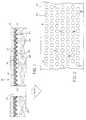
- FIG. 2view of the first embodiment of a retroreflective structure of the present invention.
- FIG. 3is a cross-sectional view of a second embodiment of the retroreflective structure of the present invention.
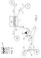
- FIG. 4is a schematic diagram of a second embodiment of the method for forming the invention.
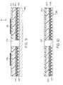
- FIG. 5is a cross-sectional view of a method for forming an alternative retroreflective structure at a first point in forming a third embodiment of the present invention.
- FIG. 6is a cross-sectional view of a method for forming an alternative retroreflective structure at a second point in forming the third embodiment of the present invention.
- FIG. 7is a cross-sectional view of a method for forming an alternative retroreflective structure at a first point in forming a fourth embodiment of the present invention.
- FIG. 8a cross-sectional view of a method for forming an alternative retroreflective structure at a second point in forming the fourth embodiment of the present invention.
- FIG. 9a cross-sectional view of a method for forming an alternative retroreflective structure at a point in forming a fifth embodiment of the present invention.
- FIG. 10is a cross-sectional view of a method for forming an alternative retroreflective structure at a point in forming a sixth embodiment of the present invention.
- FIG. 11is a cross-sectional view of a method for forming an alternative retroreflective structure at a second point in forming the sixth embodiment of the present invention.
- FIG. 12is a cross-sectional view of a method for forming an alternative retroreflective structure at a first point in forming a seventh embodiment of the present invention.
- FIG. 13is a cross-sectional view of a method for forming an alternative retroreflective structure at a second point in forming the seventh embodiment of the present invention.
- FIG. 14is a cross-sectional view of a method for forming an alternative retroreflective structure at a third point in forming the seventh embodiment of the present inventions
- FIG. 15is a cross-sectional view of a method for forming an alternative retroreflective structure at a point in forming an eighth embodiment of the present invention.
- FIG. 16is a cross-sectional view of another embodiment of a retroreflective structure of the present invention.
- FIG. 17is a cross-sectional view of yet another embodiment of the retroreflective structure of the present invention.
- FIG. 18is a cross-sectional view of another embodiment of the retroreflective structure of the present invention.
- FIG. 19is a cross-sectional view of yet another embodiment of the retroreflective structure of the present invention.
- FIG. 20is a cross-sectional view of a further embodiment of the retroreflective stature of the present invention.
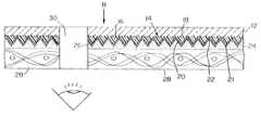
- Retroreflective structure 10has a base film 12 that is comprised of a transparent thermoplastic film, such as polyvinyl chloride, polyvinylidene chloride, urethane films, polyfluorocarbon polymers, etc.
- a transparent thermoplastic filmsuch as polyvinyl chloride, polyvinylidene chloride, urethane films, polyfluorocarbon polymers, etc.
- the thermoplasticis an ethylene-tetrafluoroethylene copolymer.
- the base film 12can be formed from an elastic material, such as flexible polyether urethanes which perform well in laundering and flexible polyaliphatic urethanes which perform well in outdoor environments.
- Base film 12is transparent to visible light and can be either clear or colored.
- An example of a suitable base film 12is a polyvinyl chloride film available from Renoliot Corp.
- Base film 12can have a thickness in the range of between about 0.001 and 0.022 inches (0.025 and 0.56 mm). In a preferred embodiment, the thickness is in the range of between about 0.008 and 0.02 inches (0.2 and 0.51 mm). The selected thickness is dependent upon the method of fabrication, such as heating, radio high frequency welding, ultrasonic welding, the thermoplastic selected, and the characteristics desired for the retroreflective structure.
- the prism array 14which can include retroreflective cube-corner prism elements 16 , is formed on the base film 12 .
- Prism array 14has a window side 18 exposed to incoming rays R and facet sides 20 and is attached on window side 18 to the base film 12 .
- Prism array 14is formed of a transparent polymer. After being formed, the polymer is preferably rigid at room temperature, which is defined as being substantially inflexible. The rigidity of the polymer in the prism array allows the prism elements to retain their optical characteristics.
- the prism array polymercan also be non-extensible, which is defined as not being capable of being substantially stretched without breaking.
- the polymeris selected from a wide variety of polymers which include the polymers of urethane, acrylic acid esters, cellulose esters, ethylenically unsaturated nitriles, hard epoxy acrylates, etc.
- Other polymersinclude polycarbonates, polyesters and polyolefins, acrylated silanes, hard polyester urethane acrylates.
- Other polymers which are not as rigidcan also be used. These include polyvinyl chloride and polyvinylidene chloride.
- the polymeris cast in a prismatic mold with a monomer or oligomer polymerization initiated by ultraviolet radiation.
- the prism elements 16 of the prism array 14can be cube-corner in shape and have a length along each cube-side edge in the range of between about 0.0015 and 0.02 inches (0.038 and 0.51 mm). In one embodiment, each cube-side edge has a length of about 0.006 inches (0.15 mm). Preferably, each cube-side edge has a length of between about 0.004 and 0.008 inches (0.1 and 0.2 mm).
- the thickness of prism array 14 at valley 22is preferably sufficiently thin so that the prism array 14 can crack and split along the valleys 22 when a minimal force is applied to retroreflective structure 10 .
- the thickness of prism array 14which is the distance from window side 18 to apex 21 of prisms, is in the range of between about 0.002 and 0.009 inches (0.05 and 0.23 mm).
- the base film 12provides a substrate for prism array 14 to provide a smooth surface upon which the prism elements can be attached.
- the window side 18 of the prism elements 16is attached to the base film 12 .
- the prism array 14can be laminated to the base film 12 with a transparent adhesive. Alternatively, the prism array 14 can be cast directly onto the base film 12 .
- An adhesive 24can be applied to the prism facets 20 for attaching a backing layer to the retroreflective structure. If an adhesive is employed on the prism facets, the adhesive can cause the surface of the prisms to wet, thereby destroying the air interface and eliminating the ability of the prism to retroreflect.
- reflective coating 26is preferably deposited on the surface of the dihedral facets 20 .
- the reflective coatingsare formed by sputtering aluminum, silver or gold or by vacuum metalization. Alternatively, metal lacquers, dielectric coatings and other specular coating materials can be employed.
- the backing layer 28is placed on the facet side 20 of the prism array 14 .
- the backing layer 28can be formed of a thermoplastic.
- backing film 28can be formed from a thermoplastic, such as a polyvinyl chloride, polyvinylidene chloride, urethane films, polyfluorocarbon polymers including an ethylene-tetrafluoroethylene copolymer, etc., which has a low temperature of distortion.
- the thermoplastic of backing layer 28can be transparent to visible light and is either clear or colored.
- backing layer 28can be a cloth or fabric, such as a polyester cloth.
- the base film 12 and backing layer 28both include polyvinyl chloride.
- the backing layer 28can be formed from an elastic material, such as flexible polyether or polyaliphatic urethanes or fabrics with built in elastic fibers, which can be formed from urethane or rubber materials.
- Backing layer 24can have a thickness in the range of between about 0.005 and 0.02 inches (0.12 and 0.51 mm).
- a plurality of apertures 30are formed in retroreflective sheeting 10 and extend through the thickness of retroreflective structure 10 .
- the aperturesare of sufficient size and spacing from one another to allow the average person to see through the otherwise opaque structure.
- the apertures 30can be formed, such as by punching holes in the structure using a suitable tool of various shapes including circles, ovals, rectangles, squares, etc. Also, the apertures can be in the shape of letters or a logo.
- Apertures 30can be uniformly or randomly arranged in an array on the structure. Typically, the apertures 30 can be circles having a diameter in the range of between about 0.25 and 0.75 inches (6.35 and 19.05 mm).
- the array of aperturescan cover about 50 percent of the surface area of the retroreflective structure.
- the aperturesprovide breathability to the structure.
- the retroreflective structurewhen superimposed over another perforated structure, can result in a moiré effect.
- Such configurationscan be incorporated into clothing or footwear to provide a decorative pattern while providing retroreflectivity for safety.
- the base film and prism array portion of one embodiment of the retroreflective structure 10can be formed by one of the methods disclosed in U.S. Pat. No. 3,684,348, issued to Rowland on Aug. 15, 1972; U.S. Pat. No. 3,689,346, issued to Rowland on Sep. 5, 1972; U.S. Pat. No. 3,811,983, issued to Rowland on May 21, 1974; U.S. Pat. No. 3,830,682, issued to Rowland on Aug. 20, 1974; U.S. Pat. No. 3,975,083, issued to Rowland on Aug. 17, 1976; U.S. Pat. No. 4,332,847, issued to Rowland on Jun. 1, 1982; U.S. Pat. No.
- a six mil (0.15 mm) polyvinyl chloride filmis laminated to a two mil (0.05 mm) polyethylene terepthalate (PET) carrier.
- the polyvinyl chloride filmis tie coated and retroreflective prisms are cast on the tie coated polyvinyl chloride film.
- the retroreflective prismsare metalized.
- the metalized layermay or may not need to be protected by a coating of some type depending on the application requirements.
- a coloreither the same color as the top surface or another
- a top view of the retroreflective structureis shown in FIG. 2 .
- a metalized retroreflective structure film 100formed as described above, is unwound from roll 102 and directed to a device 104 , such as a step and repeat die punch system, for punching apertures in retroreflective structure film 100 .
- the metalized retroreflective structure film 100is wound up at windup station 106 .
- the punched particles 50 of retroreflective film described in detail above and shown in FIG. 3drop onto auto platen 105 and are collected from platen 105 .
- FIG. 1As shown in FIG.
- the particles 50can be directly applied from device 104 to an adhesive coated substrate 110 , such as a fabric, which is unwound from fabric roll 112 , as shown in FIG. 4 .
- Particles 50can also be dispersed onto the adhesive side 113 of the adhesive coated substrate 110 from particle dispenser 114 .
- Pinch rollers 116press the particles against adhesive coated substrate 110 . Any loose particles are caught in tray 118 as the adhesive coated substrate and particles exit pinch rollers 116 .
- Top film 122is unrolled from top film roller 124 and is laminated to adhesive coated substrate with particles in between the two layers by laminating rollers 126 .
- the laminated structure 127is wound up on windup roller 128 .
- the particlesare suitable for use as decorative or conspicuity particles on clothing, T-shirt signs, pavement marking lines, traffic signs, bicycle helmets, tarpaulins, etc.
- the particlescan be mixed in a gel and applied to a substrate.
- the particlesFor use in low temperature processes (below the melting temperature of PET or polyvinyl chloride), the particles stay intact within the plastic substrate during lamination.
- the polymer processing temperatureexceeds the melting point of PET, the film deforms but the thermoset prisms and/or reflective coating remains intact.
- the perforated retroreflective structurecan be applied to the inside of a window.
- polyvinyl film 140is laminated to a carrier film 142 , and the polyvinyl film 140 is coated with tie coat 144 .
- Prisms 146are cast on the tie coat 144 and the prisms are silver metalized.
- the structureis perforated with a stamping device to form aperture 150 .
- a barrier film 152such as paper or polypropylene, is added to the metalized side 148 with an adhesive 151 to provide dimensional stiffness and allows the film to be ink jet printed.
- the carrier filmis removed and the polyvinyl film is either screen printed or ink jet printed using plasticol inks 154 .
- the surface of the polyvinyl film 140has a static cling property, thereby allowing the structure to be applied on the inside of a window 156 .
- Screen printingis a preferred embodiment for long runs or ultraviolet light resistant applications.
- a PET filmcan be used for the top layer for printing on.
- a dye receptive filmcan be formed on or attached to the polyvinyl film 140 for reception of inks and the like.
- the perforated retroreflective structurecan be applied to the outside of a window.
- a method for forming the structureincludes applying a tie coat 160 to PET film 162 .
- Prisms 164are cast on the tie coat 160 and then metalized to form metalized layer 166 .
- the metalized prismsare coated with a removable acrylic-based adhesive 168 , preferably with a black pigment incorporated therein, and a silicone coated paper release liner is applied to the acrylic-based adhesive.
- the filmis perforated with a perforator to form aperture 172 .
- a barrier film 174such as paper or polypropylene, is attached to the release liner 170 to provide additional dimensional stiffness.
- the filmcan then be printed on the exposed PET side with screening 176 , ink jet printing or another suitable method.
- Ink jet printerscan be a pigmented solvent system that can offer ultraviolet light resistance for about twelve months.
- the temporary release liner 170is removed and the retroreflective structure can be attached to the outside of a window 180 .
- a polyvinyl filmcan be laminated to a carrier film, such as a two mil (0.05 mm) PET film 162 , and then the polyvinyl film 182 is tie coated. Retroreflective prism elements are cast on the tie coat 160 and then are metalized. The metalized prisms are coated and the carrier film is printed on by a similar step as discussed in the prior paragraph. The structure can be applied to the outside of a window.
- a carrier filmsuch as a two mil (0.05 mm) PET film 162
- Retroreflective prism elementsare cast on the tie coat 160 and then are metalized.
- the metalized prismsare coated and the carrier film is printed on by a similar step as discussed in the prior paragraph.
- the structurecan be applied to the outside of a window.
- a transflector material for use in airport signsis typically back lit, but it needs to be retroreflective in the event of a power outage.
- the transflector materialshown in FIG. 10, is formed by laminating a polyvinyl film 200 to a carrier film 202 , such as PET, and the polyvinyl film is coated with a tie coat 206 .
- Prisms 208are cast on the tie coat 206 .
- the prisms 208are metalized with metal layer 210 .
- the filmis perforated to form apertures 212 .
- the perforated filmis laminated to a white diffuse film 214 . Shown in FIG. 11, the carrier film is then removed from the vinyl film.
- a transparent adhesive 216is applied to the polyvinyl film, and the film is applied to a silk screen-type printed sheet 218 of transparent material for use in a sign.
- the printed sheet 218can be formed from polyvinyl chloride, polymethyl methacrylate (PMMA), or other suitable materials.
- a coatingcan be provided over the printed sheet 218 for purposes such as preventing abrasions to the printed sheet.
- a seamless graphic film 220can be formed to hide or remove seam lines created by a mold.
- the seam lines 222are removed by cutting out as much of the seam lines as possible and replacing them with glass beads 224 .
- a polyvinyl prismatic internal reflective element film 226 with prisms 228 laminated with a PET carrier film 232is perforated to form apertures 234 .
- the PET carrier film 232is removed from the perforated vinyl prismatic film 226 .
- the perforated retroreflective prismatic film 226is coated with a light tack removable adhesive so that the reflective surface (window surface) is in contact with the adhesive.
- Beads 224preferably high refractive index glass beads, are coated on the film 220 .
- the beads 224attach where the beads are exposed to the adhesive 236 in the apertures 234 of the vinyl prismatic film 220 .
- the facets of the prisms 228 and the attached beadsare metalized with metalized layer 230 .
- metalized one or two sided corner cube chips or particlesmay be bonded to the exposed adhesive to provide additional retroreflective area, glitter effects, and/or color effects.
- the particlescan also include metalized “open-face” cube-corner prisms, such as taught in U.S. application No. 09/488,129, filed Jan. 20, 2000, the teachings of which are incorporated herein by reference.
- the corner cubesmay be of a different size than the corner cubes formed on the film 226 .
- base adhesive 238preferably a white adhesive
- a backing film 240are applied to the metalized layer 230 .
- the low-tack adhesive 236is removed and the film is coated with a flexible transparent weatherable ink receptive system 242 .
- the formed structureprovides a balanced set of properties with good narrow observation for long distance sight detection and with good angularity for viewing at short distances.
- a flexible film having prisms 252 cast on a tie coat 253 and metalized layer 254 on the facets of the prismsis perforated to form apertures 256 .
- the perforated filmis laminated using an adhesive 257 to a fabric backed material 258 .
- the filmis then extrusion coated with a clear abrasion and ultraviolet light resistant material 260 , such as polyvinyl chloride or polyurethane.
- colored PET glitter pieces 262are coated onto the surface of perforated film which attaches to the areas where the adhesive is present in the perforations to provide a partially glitter-coated perforated reflective film.
- white ultraviolet curable inkeither on the facets of the prisms or in the tie coat on the window side of the prisms, is used to achieve the necessary Cap Y to meet industry whiteness specifications. While the white printing enhances the Cap Y performance, it also destroys the retroreflectivity of the prisms it covers, thereby effectively destroying sometimes about thirty percent of the retroreflectivity.
- the white printingcan be in the form of a logo, lettering, etc.
- the step of printingcan expose the prismatic film to excessive heat which can negatively impact the resulting retroreflectivity. Further, printing on the tie coat reduces the run speeds because of the difficulty in curing the prisms.
- FIG. 16illustrates another embodiment of a retroreflective structure 10 ′ in accordance with the invention.
- This embodimentis similar to the embodiment of FIG. 1 but further includes a second prism array 14 ′, which is formed on the base film 12 ′, attached to a second side of the layer 28 .
- a second prism array 14 ′which is formed on the base film 12 ′, attached to a second side of the layer 28 .
- light rays Rare retroreflected from both sides of the structure 10 ′.
- a plurality of apertures 30are formed in the retroreflective sheeting 10 ′.
- the punched particles 51 ′ from apertures 30as shown in FIG. 17, can be used for decorative or conspicuity purposes.
- FIG. 18illustrate another embodiment of a retroreflective structure which includes a second base film 12 ′ having a prism array 14 ′. This arrangement provides additional retroreflectivity in the aperture 30 area.
- the prism array 14 ′can further include a reflective coating deposited on the surface of the dihedral facets 20 ′.
- backing layer 28can be attached to the prism area 14 ′.
- FIG. 19is similar to FIG. 18 and further includes backing layer 28 disposed between the prism arrays 14 and 14 ′.
- FIG. 20illustrates a further embodiment of a retroreflective structure in which the prism array 14 ′ and base film 12 ′ as disposed on the top side of the film.
- the prism array 14 ′is bonded to the base film 12 by a substantially clear adhesive 15 .
- the prisms suspended over the apertures 30are air-backed and provide retroreflection at the apertures.
- the remaining prismsare “wetted-out” by the adhesive 15 and do not provide retroreflection.
Landscapes
- Physics & Mathematics (AREA)
- General Physics & Mathematics (AREA)
- Optics & Photonics (AREA)
- Optical Elements Other Than Lenses (AREA)
Abstract
Description
Claims (44)
Priority Applications (2)
| Application Number | Priority Date | Filing Date | Title |
|---|---|---|---|
| US09/730,522US6481857B2 (en) | 1997-12-16 | 2000-12-05 | Perforated retroreflective film |
| US10/254,957US6736519B2 (en) | 1997-12-16 | 2002-09-25 | Perforated retroreflective film |
Applications Claiming Priority (3)
| Application Number | Priority Date | Filing Date | Title |
|---|---|---|---|
| US6981897P | 1997-12-16 | 1997-12-16 | |
| US09/211,962US6155689A (en) | 1997-12-16 | 1998-12-15 | Perforated retroreflective film |
| US09/730,522US6481857B2 (en) | 1997-12-16 | 2000-12-05 | Perforated retroreflective film |
Related Parent Applications (1)
| Application Number | Title | Priority Date | Filing Date |
|---|---|---|---|
| US09/211,962Continuation-In-PartUS6155689A (en) | 1997-12-16 | 1998-12-15 | Perforated retroreflective film |
Related Child Applications (1)
| Application Number | Title | Priority Date | Filing Date |
|---|---|---|---|
| US10/254,957ContinuationUS6736519B2 (en) | 1997-12-16 | 2002-09-25 | Perforated retroreflective film |
Publications (2)
| Publication Number | Publication Date |
|---|---|
| US20010017731A1 US20010017731A1 (en) | 2001-08-30 |
| US6481857B2true US6481857B2 (en) | 2002-11-19 |
Family
ID=26750459
Family Applications (2)
| Application Number | Title | Priority Date | Filing Date |
|---|---|---|---|
| US09/730,522Expired - LifetimeUS6481857B2 (en) | 1997-12-16 | 2000-12-05 | Perforated retroreflective film |
| US10/254,957Expired - LifetimeUS6736519B2 (en) | 1997-12-16 | 2002-09-25 | Perforated retroreflective film |
Family Applications After (1)
| Application Number | Title | Priority Date | Filing Date |
|---|---|---|---|
| US10/254,957Expired - LifetimeUS6736519B2 (en) | 1997-12-16 | 2002-09-25 | Perforated retroreflective film |
Country Status (1)
| Country | Link |
|---|---|
| US (2) | US6481857B2 (en) |
Cited By (12)
| Publication number | Priority date | Publication date | Assignee | Title |
|---|---|---|---|---|
| US20050185279A1 (en)* | 1999-01-21 | 2005-08-25 | Reflexite Corporation | Durable, open-faced retroreflective prismatic construction |
| US20050221042A1 (en)* | 2004-04-01 | 2005-10-06 | 3M Innovative Properties Company | Retroreflective sheeting with controlled cap-Y |
| US20060019092A1 (en)* | 2004-03-24 | 2006-01-26 | Carine Lefevre | Method of forming a breathable film cover |
| US20060091693A1 (en)* | 2004-11-02 | 2006-05-04 | Waveland Industries, Inc. | Removable visor |
| US20070008113A1 (en)* | 2005-06-20 | 2007-01-11 | Eastman Kodak Company | System to monitor the ingestion of medicines |
| US20070008112A1 (en)* | 2005-06-20 | 2007-01-11 | Edward Covannon | System to monitor the ingestion of medicines |
| KR100813322B1 (en) | 2006-09-06 | 2008-03-12 | 김태일 | Light reflecting sheet and its manufacturing method |
| US20090027775A1 (en)* | 2007-07-26 | 2009-01-29 | Nilsen Robert B | Multiple layer reflective tag |
| US20090249666A1 (en)* | 2008-04-03 | 2009-10-08 | George Conant | Method of and system for two-way see-through banner and window imaging |
| US20120188640A1 (en)* | 2009-07-20 | 2012-07-26 | Tufts University/Trustees Of Tufts College | All-protein implantable, resorbable reflectors |
| WO2014059496A1 (en)* | 2012-10-16 | 2014-04-24 | Assunç O Tavares Antonio Sergio | Method for producing reflective laminates for thermal and solar radiation control, and resulting products |
| US10145672B2 (en) | 2017-01-24 | 2018-12-04 | Lithoptek LLC | Detection of position, orientation and scale of work pieces using retroreflective surfaces |
Families Citing this family (31)
| Publication number | Priority date | Publication date | Assignee | Title |
|---|---|---|---|---|
| ITMO20020205A1 (en)* | 2002-07-17 | 2004-01-19 | Giorgio Corradi | MULTI-LAYER REAR-REFLECTIVE FILM, IN PARTICULAR OF THE MICROPRISM TYPE |
| ES2256806T3 (en)* | 2003-04-04 | 2006-07-16 | Andre Fiechter | POSTER AS WELL AS PROCEDURE AND MATERIALS FOR MANUFACTURING. |
| KR100586406B1 (en)* | 2004-06-11 | 2006-06-08 | 김현대 | Cube corner type retroreflective device manufacturing method and retroreflective device |
| CN100468814C (en)* | 2004-12-15 | 2009-03-11 | 鸿富锦精密工业(深圳)有限公司 | organic light emitting display |
| AU2006303862B2 (en)* | 2005-10-21 | 2010-10-07 | Impact Holdings Australia Pty Ltd | A method of producing perforated retroreflective trim |
| ES2380549T3 (en)* | 2005-10-21 | 2012-05-16 | Video Taped Transcripts Pty. Ltd. | A method to produce a perforated retroreflective lining |
| US7897230B2 (en)* | 2007-04-30 | 2011-03-01 | Clear Focus Imaging, Inc. | One-way vision display panels with retention layer |
| USD603611S1 (en)* | 2007-11-19 | 2009-11-10 | The Procter & Gamble Company | Absorbent article material |
| US20090169795A1 (en)* | 2007-12-26 | 2009-07-02 | Andre Fiechter | Poster as well as methods and materials for its manufacture |
| US20100155288A1 (en)* | 2008-12-15 | 2010-06-24 | Alcan Technology & Management Ltd | Multi-layer laminate material |
| US20100313455A1 (en)* | 2009-06-11 | 2010-12-16 | Se-Kwon Kim | Advertising sheet laminate |
| JP2011186414A (en)* | 2010-02-12 | 2011-09-22 | Sony Corp | Optical device, sun screening apparatus, fitting, window material, and method of producing optical device |
| JP5745776B2 (en)* | 2010-03-15 | 2015-07-08 | デクセリアルズ株式会社 | Optical laminate and joinery |
| TWM388651U (en)* | 2010-03-18 | 2010-09-11 | Dayu Optoelectronics Co Ltd | Optical retroreflective apparatus |
| JP6074128B2 (en)* | 2010-04-15 | 2017-02-01 | デクセリアルズ株式会社 | Optical body and manufacturing method thereof, solar shading member, window material, interior member and fitting |
| US8662854B1 (en) | 2010-05-21 | 2014-03-04 | Fastskinz, Inc. | Turbine with turbulence inducing surface |
| JP5508946B2 (en)* | 2010-06-16 | 2014-06-04 | デクセリアルズ株式会社 | Optical body, window material, joinery, solar shading device, and building |
| US8682030B2 (en) | 2010-09-24 | 2014-03-25 | Microsoft Corporation | Interactive display |
| USD677196S1 (en)* | 2011-10-13 | 2013-03-05 | Fastskinz, Inc. | Set of drag reducing panels for a road tractor |
| USD704112S1 (en) | 2011-10-14 | 2014-05-06 | Fastskinz, Inc. | Day cab road tractor with drag-reducing film system |
| US11366284B2 (en) | 2011-11-22 | 2022-06-21 | Cognex Corporation | Vision system camera with mount for multiple lens types and lens module for the same |
| US8947590B2 (en) | 2011-11-22 | 2015-02-03 | Cognex Corporation | Vision system camera with mount for multiple lens types |
| NL2011351C2 (en)* | 2013-08-28 | 2015-05-26 | Codan B V | REFLECTION MATERIAL, SEMI-MANUFACTURE, REFLECTOR, METHOD AND USE THEREOF. |
| US10451780B2 (en)* | 2013-12-12 | 2019-10-22 | 3M Innovative Properties Company | Retroreflective article |
| US9653044B2 (en) | 2014-02-14 | 2017-05-16 | Microsoft Technology Licensing, Llc | Interactive display system |
| WO2018027071A1 (en)* | 2016-08-03 | 2018-02-08 | Mirraviz, Inc. | Real time algorithmic calibration and compensation of virtual and augmented reality systems and optimized semi-transparent and transparent retroreflective display systems and methods |
| JP7043211B2 (en)* | 2017-10-12 | 2022-03-29 | 日本カーバイド工業株式会社 | Retroreflective sheet |
| EP3702816A1 (en)* | 2019-02-28 | 2020-09-02 | D. Swarovski KG | Decorative composite body |
| CN111025443A (en)* | 2019-11-20 | 2020-04-17 | 福建夜光达科技股份有限公司 | Retro-reflection film with double-sided light reflection function and manufacturing process thereof |
| ES2894924B2 (en)* | 2020-08-10 | 2023-09-07 | Masdeu Rosa Castaner | MANUFACTURING METHOD OF TEXTILE SEQUINS |
| US12306423B1 (en)* | 2020-08-13 | 2025-05-20 | Kevin Patrick McMahon | Sensor activated anti-collision device |
Citations (28)
| Publication number | Priority date | Publication date | Assignee | Title |
|---|---|---|---|---|
| US3684348A (en) | 1970-09-29 | 1972-08-15 | Rowland Dev Corp | Retroreflective material |
| US3689346A (en) | 1970-09-29 | 1972-09-05 | Rowland Dev Corp | Method for producing retroreflective material |
| US3712706A (en) | 1971-01-04 | 1973-01-23 | American Cyanamid Co | Retroreflective surface |
| US3811983A (en) | 1972-06-23 | 1974-05-21 | Rowland Dev Corp | Method for producing retroreflective sheeting |
| US3830682A (en) | 1972-11-06 | 1974-08-20 | Rowland Dev Corp | Retroreflecting signs and the like with novel day-night coloration |
| US3975083A (en) | 1974-07-24 | 1976-08-17 | Reflexite Corporation | Wide angle retroreflector assembly and method of making same |
| US4103060A (en) | 1975-01-10 | 1978-07-25 | Minnesota Mining And Manufacturing Company | Area-retroreflectorization of fabrics |
| US4332847A (en) | 1979-09-20 | 1982-06-01 | Relfexite Corporation | Method for compression molding of retroreflective sheeting and sheeting produced thereby |
| US4712868A (en) | 1985-09-23 | 1987-12-15 | Minnesota Mining And Manufacturing Company | Expanded retroreflective sheet material |
| US4801193A (en) | 1988-03-04 | 1989-01-31 | Reflexite Corporation | Retroreflective sheet material and method of making same |
| US5202168A (en) | 1990-09-18 | 1993-04-13 | Northrop Corporation | Precision retro-reflective target tape |
| US5229882A (en) | 1990-05-16 | 1993-07-20 | Reflexite Corporation | Colored retroreflective sheeting and method of making same |
| US5236751A (en) | 1991-03-28 | 1993-08-17 | Reflexite Corporation | Cone collars with temporary release coating and method for making and assembling same |
| US5264063A (en) | 1990-05-16 | 1993-11-23 | Reflexite Corporation | Method for making flexible retroreflective sheet material |
| US5376431A (en) | 1993-05-12 | 1994-12-27 | Reflexite Corporation | Retroreflective microprism sheeting with silver/copper reflecting coating and method of making same |
| US5491586A (en) | 1993-07-19 | 1996-02-13 | Reflexite Corporation | Elastomeric retroreflective structure |
| US5512219A (en) | 1994-06-03 | 1996-04-30 | Reflexite Corporation | Method of casting a microstructure sheet having an array of prism elements using a reusable polycarbonate mold |
| US5525177A (en) | 1994-09-01 | 1996-06-11 | Clear Focus Imaging, Inc. | Image transfer method for one way vision display panel |
| US5550346A (en) | 1994-06-21 | 1996-08-27 | Andriash; Myke D. | Laser sheet perforator |
| US5558740A (en) | 1995-05-19 | 1996-09-24 | Reflexite Corporation | Method and apparatus for producing seamless retroreflective sheeting |
| US5592330A (en) | 1995-05-19 | 1997-01-07 | Reflexite Corporation | Retroreflective prism arrays with formed air spheres therein |
| US5614286A (en) | 1993-10-20 | 1997-03-25 | Minnesota Mining And Manufacturing Company | Conformable cube corner retroreflective sheeting |
| US5637173A (en) | 1993-02-17 | 1997-06-10 | Reflexite Corporation | Method for forming a retroreflective structure having free-standing prisms |
| US5679435A (en) | 1994-06-21 | 1997-10-21 | Andriash; Michael D. | Vision control panels with perforations and method of making |
| US5831766A (en) | 1993-02-17 | 1998-11-03 | Reflexite Corporation | Retroreflective structure |
| US5925437A (en)* | 1997-10-23 | 1999-07-20 | Nelson; Stephen G. | See-through panel assembly with retroreflective surface and method of making same |
| US5939168A (en) | 1994-06-21 | 1999-08-17 | Andriash; Michael D. | Vision control panel for displaying discrete images observable from one side of the panel and method of making |
| US6155689A (en) | 1997-12-16 | 2000-12-05 | Reflexite Corporation | Perforated retroreflective film |
Family Cites Families (3)
| Publication number | Priority date | Publication date | Assignee | Title |
|---|---|---|---|---|
| US4769265A (en)* | 1983-01-10 | 1988-09-06 | Coburn Jr Joseph W | Laminated decorative film and methods of making same |
| EP1008869A3 (en)* | 1993-11-17 | 2001-08-08 | Reflec PLC | Retroreflective materials |
| US6143224A (en)* | 1995-05-18 | 2000-11-07 | Reflexite Corporation | Method for forming a retroreflective sheeting |
- 2000
- 2000-12-05USUS09/730,522patent/US6481857B2/ennot_activeExpired - Lifetime
- 2002
- 2002-09-25USUS10/254,957patent/US6736519B2/ennot_activeExpired - Lifetime
Patent Citations (29)
| Publication number | Priority date | Publication date | Assignee | Title |
|---|---|---|---|---|
| US3684348A (en) | 1970-09-29 | 1972-08-15 | Rowland Dev Corp | Retroreflective material |
| US3689346A (en) | 1970-09-29 | 1972-09-05 | Rowland Dev Corp | Method for producing retroreflective material |
| US3712706A (en) | 1971-01-04 | 1973-01-23 | American Cyanamid Co | Retroreflective surface |
| US3811983A (en) | 1972-06-23 | 1974-05-21 | Rowland Dev Corp | Method for producing retroreflective sheeting |
| US3830682A (en) | 1972-11-06 | 1974-08-20 | Rowland Dev Corp | Retroreflecting signs and the like with novel day-night coloration |
| US3975083A (en) | 1974-07-24 | 1976-08-17 | Reflexite Corporation | Wide angle retroreflector assembly and method of making same |
| US4103060A (en) | 1975-01-10 | 1978-07-25 | Minnesota Mining And Manufacturing Company | Area-retroreflectorization of fabrics |
| US4332847A (en) | 1979-09-20 | 1982-06-01 | Relfexite Corporation | Method for compression molding of retroreflective sheeting and sheeting produced thereby |
| US4712868A (en) | 1985-09-23 | 1987-12-15 | Minnesota Mining And Manufacturing Company | Expanded retroreflective sheet material |
| US4801193A (en) | 1988-03-04 | 1989-01-31 | Reflexite Corporation | Retroreflective sheet material and method of making same |
| US5229882A (en) | 1990-05-16 | 1993-07-20 | Reflexite Corporation | Colored retroreflective sheeting and method of making same |
| US5264063A (en) | 1990-05-16 | 1993-11-23 | Reflexite Corporation | Method for making flexible retroreflective sheet material |
| US5202168A (en) | 1990-09-18 | 1993-04-13 | Northrop Corporation | Precision retro-reflective target tape |
| US5236751A (en) | 1991-03-28 | 1993-08-17 | Reflexite Corporation | Cone collars with temporary release coating and method for making and assembling same |
| US5637173A (en) | 1993-02-17 | 1997-06-10 | Reflexite Corporation | Method for forming a retroreflective structure having free-standing prisms |
| US5831766A (en) | 1993-02-17 | 1998-11-03 | Reflexite Corporation | Retroreflective structure |
| US5376431A (en) | 1993-05-12 | 1994-12-27 | Reflexite Corporation | Retroreflective microprism sheeting with silver/copper reflecting coating and method of making same |
| US5642222A (en) | 1993-07-19 | 1997-06-24 | Reflexite Corporation | Elastomeric retroreflective structure |
| US5491586A (en) | 1993-07-19 | 1996-02-13 | Reflexite Corporation | Elastomeric retroreflective structure |
| US5614286A (en) | 1993-10-20 | 1997-03-25 | Minnesota Mining And Manufacturing Company | Conformable cube corner retroreflective sheeting |
| US5512219A (en) | 1994-06-03 | 1996-04-30 | Reflexite Corporation | Method of casting a microstructure sheet having an array of prism elements using a reusable polycarbonate mold |
| US5550346A (en) | 1994-06-21 | 1996-08-27 | Andriash; Myke D. | Laser sheet perforator |
| US5679435A (en) | 1994-06-21 | 1997-10-21 | Andriash; Michael D. | Vision control panels with perforations and method of making |
| US5939168A (en) | 1994-06-21 | 1999-08-17 | Andriash; Michael D. | Vision control panel for displaying discrete images observable from one side of the panel and method of making |
| US5525177A (en) | 1994-09-01 | 1996-06-11 | Clear Focus Imaging, Inc. | Image transfer method for one way vision display panel |
| US5558740A (en) | 1995-05-19 | 1996-09-24 | Reflexite Corporation | Method and apparatus for producing seamless retroreflective sheeting |
| US5592330A (en) | 1995-05-19 | 1997-01-07 | Reflexite Corporation | Retroreflective prism arrays with formed air spheres therein |
| US5925437A (en)* | 1997-10-23 | 1999-07-20 | Nelson; Stephen G. | See-through panel assembly with retroreflective surface and method of making same |
| US6155689A (en) | 1997-12-16 | 2000-12-05 | Reflexite Corporation | Perforated retroreflective film |
Cited By (24)
| Publication number | Priority date | Publication date | Assignee | Title |
|---|---|---|---|---|
| US20050185279A1 (en)* | 1999-01-21 | 2005-08-25 | Reflexite Corporation | Durable, open-faced retroreflective prismatic construction |
| US20060019092A1 (en)* | 2004-03-24 | 2006-01-26 | Carine Lefevre | Method of forming a breathable film cover |
| US7022406B1 (en) | 2004-03-24 | 2006-04-04 | Morgan Adhesives Company | Breathable film cover for window panes |
| US20070048501A1 (en)* | 2004-04-01 | 2007-03-01 | 3M Innovative Properties Company | Formation of retroreflective sheeting with controlled cap-y |
| US20050221042A1 (en)* | 2004-04-01 | 2005-10-06 | 3M Innovative Properties Company | Retroreflective sheeting with controlled cap-Y |
| US7329447B2 (en) | 2004-04-01 | 2008-02-12 | 3M Innovative Properties Company | Retroreflective sheeting with controlled cap-Y |
| US20060091693A1 (en)* | 2004-11-02 | 2006-05-04 | Waveland Industries, Inc. | Removable visor |
| US7616111B2 (en) | 2005-06-20 | 2009-11-10 | Carestream Health, Inc. | System to monitor the ingestion of medicines |
| US9058530B2 (en) | 2005-06-20 | 2015-06-16 | Carestream Health, Inc. | System to monitor the ingestion of medicines |
| US9659476B2 (en) | 2005-06-20 | 2017-05-23 | Carestream Health, Inc. | System to monitor the ingestion of medicines |
| US9183724B2 (en) | 2005-06-20 | 2015-11-10 | Carestream Health, Inc. | System to monitor the ingestion of medicines |
| US20070008112A1 (en)* | 2005-06-20 | 2007-01-11 | Edward Covannon | System to monitor the ingestion of medicines |
| US20070008113A1 (en)* | 2005-06-20 | 2007-01-11 | Eastman Kodak Company | System to monitor the ingestion of medicines |
| US20100052900A1 (en)* | 2005-06-20 | 2010-03-04 | Edward Covannon | System to monitor the ingestion of medicines |
| US7782189B2 (en) | 2005-06-20 | 2010-08-24 | Carestream Health, Inc. | System to monitor the ingestion of medicines |
| US8564432B2 (en) | 2005-06-20 | 2013-10-22 | Carestream Health, Inc. | System to monitor the ingestion of medicines |
| KR100813322B1 (en) | 2006-09-06 | 2008-03-12 | 김태일 | Light reflecting sheet and its manufacturing method |
| US20090027775A1 (en)* | 2007-07-26 | 2009-01-29 | Nilsen Robert B | Multiple layer reflective tag |
| US8112923B2 (en) | 2008-04-03 | 2012-02-14 | Meisel Photographic Corporation | Method of and system for two-way see-through banner and window imaging |
| US20090249666A1 (en)* | 2008-04-03 | 2009-10-08 | George Conant | Method of and system for two-way see-through banner and window imaging |
| US20120188640A1 (en)* | 2009-07-20 | 2012-07-26 | Tufts University/Trustees Of Tufts College | All-protein implantable, resorbable reflectors |
| US9016875B2 (en)* | 2009-07-20 | 2015-04-28 | Tufts University/Trustees Of Tufts College | All-protein implantable, resorbable reflectors |
| WO2014059496A1 (en)* | 2012-10-16 | 2014-04-24 | Assunç O Tavares Antonio Sergio | Method for producing reflective laminates for thermal and solar radiation control, and resulting products |
| US10145672B2 (en) | 2017-01-24 | 2018-12-04 | Lithoptek LLC | Detection of position, orientation and scale of work pieces using retroreflective surfaces |
Also Published As
| Publication number | Publication date |
|---|---|
| US20010017731A1 (en) | 2001-08-30 |
| US6736519B2 (en) | 2004-05-18 |
| US20030021030A1 (en) | 2003-01-30 |
Similar Documents
| Publication | Publication Date | Title |
|---|---|---|
| US6481857B2 (en) | Perforated retroreflective film | |
| US6155689A (en) | Perforated retroreflective film | |
| EP1015915B1 (en) | Glittering cube-corner retroreflective sheeting | |
| US5814355A (en) | Mold for producing glittering cube-corner retroreflective sheeting | |
| EP0896683B1 (en) | Method of making glittering cube-corner retroreflective sheeting | |
| AU597806B2 (en) | Retroreflective sheeting with backing film | |
| EP0223564B1 (en) | Transparent multi-layer cover film for retroreflective sheeting | |
| EP1080383B1 (en) | Method of making a prefabricated retroreflective sign | |
| JP4618895B2 (en) | Open-surface retroreflective prism structure with excellent durability | |
| US20050185279A1 (en) | Durable, open-faced retroreflective prismatic construction | |
| US6656307B2 (en) | Method of making signs having metalized cube corner sheeting | |
| US20060046159A1 (en) | Methods of manufacturing substrates with multiple images | |
| EP1787276B1 (en) | Substrates with multiple images and methods of use | |
| JP2008511866A (en) | Substrate with multiple images | |
| HK1034576A (en) | Perforated retroreflective film | |
| US7416776B2 (en) | Substrates with multiple images | |
| US7404997B2 (en) | Substrates with multiple images |
Legal Events
| Date | Code | Title | Description |
|---|---|---|---|
| AS | Assignment | Owner name:REFLEXITE CORPORATION, CONNECTICUT Free format text:ASSIGNMENT OF ASSIGNORS INTEREST;ASSIGNOR:SMITH, PETER R.;REEL/FRAME:011717/0314 Effective date:20010312 | |
| STCF | Information on status: patent grant | Free format text:PATENTED CASE | |
| CC | Certificate of correction | ||
| AS | Assignment | Owner name:FLEET NATIONAL BANK, CONNECTICUT Free format text:SECURITY AGREEMENT;ASSIGNOR:REFLEXITE CORPORATION;REEL/FRAME:015242/0221 Effective date:20040923 | |
| FPAY | Fee payment | Year of fee payment:4 | |
| FEPP | Fee payment procedure | Free format text:PAYOR NUMBER ASSIGNED (ORIGINAL EVENT CODE: ASPN); ENTITY STATUS OF PATENT OWNER: LARGE ENTITY | |
| AS | Assignment | Owner name:ARES CAPITAL CORP., NEW YORK Free format text:SECURITY AGREEMENT;ASSIGNOR:REFLEXITE CORPORATION;REEL/FRAME:022086/0665 Effective date:20090109 | |
| FEPP | Fee payment procedure | Free format text:PAYER NUMBER DE-ASSIGNED (ORIGINAL EVENT CODE: RMPN); ENTITY STATUS OF PATENT OWNER: LARGE ENTITY Free format text:PAYOR NUMBER ASSIGNED (ORIGINAL EVENT CODE: ASPN); ENTITY STATUS OF PATENT OWNER: LARGE ENTITY | |
| FPAY | Fee payment | Year of fee payment:8 | |
| FEPP | Fee payment procedure | Free format text:PAT HOLDER NO LONGER CLAIMS SMALL ENTITY STATUS, ENTITY STATUS SET TO UNDISCOUNTED (ORIGINAL EVENT CODE: STOL); ENTITY STATUS OF PATENT OWNER: LARGE ENTITY | |
| AS | Assignment | Owner name:REFLEXITE CORPORATION, CONNECTICUT Free format text:RELEASE BY SECURED PARTY;ASSIGNOR:ARES CAPITAL CORPORATION;REEL/FRAME:027256/0708 Effective date:20110826 | |
| AS | Assignment | Owner name:REFLEXITE CORPORATION, CONNECTICUT Free format text:RELEASE BY SECURED PARTY;ASSIGNOR:BANK OF AMERICA, N.A., AS SUCCESSOR IN INTEREST TO FLEET NATIONAL BANK;REEL/FRAME:027256/0950 Effective date:20110826 | |
| AS | Assignment | Owner name:BANK OF AMERICA, N.A., CONNECTICUT Free format text:PATENT COLLATERAL ASSIGNMENT AND SECURITY AGREEMENT;ASSIGNOR:REFLEXITE CORPORATION;REEL/FRAME:027354/0839 Effective date:20111207 | |
| AS | Assignment | Owner name:ORAFOL AMERICAS INC., CONNECTICUT Free format text:CHANGE OF NAME;ASSIGNOR:REFLEXITE CORPORATION;REEL/FRAME:029462/0932 Effective date:20121015 | |
| FPAY | Fee payment | Year of fee payment:12 |