US6481756B1 - Coupling assembly - Google Patents
Coupling assemblyDownload PDFInfo
- Publication number
- US6481756B1 US6481756B1US09/703,256US70325600AUS6481756B1US 6481756 B1US6481756 B1US 6481756B1US 70325600 AUS70325600 AUS 70325600AUS 6481756 B1US6481756 B1US 6481756B1
- Authority
- US
- United States
- Prior art keywords
- coupling assembly
- coupling
- male
- male coupling
- female body
- Prior art date
- Legal status (The legal status is an assumption and is not a legal conclusion. Google has not performed a legal analysis and makes no representation as to the accuracy of the status listed.)
- Expired - Lifetime, expires
Links
Images


Classifications
- F—MECHANICAL ENGINEERING; LIGHTING; HEATING; WEAPONS; BLASTING
- F16—ENGINEERING ELEMENTS AND UNITS; GENERAL MEASURES FOR PRODUCING AND MAINTAINING EFFECTIVE FUNCTIONING OF MACHINES OR INSTALLATIONS; THERMAL INSULATION IN GENERAL
- F16L—PIPES; JOINTS OR FITTINGS FOR PIPES; SUPPORTS FOR PIPES, CABLES OR PROTECTIVE TUBING; MEANS FOR THERMAL INSULATION IN GENERAL
- F16L29/00—Joints with fluid cut-off means
- F16L29/005—Joints with fluid cut-off means joints with cut-off devices which can be perforated
- F—MECHANICAL ENGINEERING; LIGHTING; HEATING; WEAPONS; BLASTING
- F16—ENGINEERING ELEMENTS AND UNITS; GENERAL MEASURES FOR PRODUCING AND MAINTAINING EFFECTIVE FUNCTIONING OF MACHINES OR INSTALLATIONS; THERMAL INSULATION IN GENERAL
- F16L—PIPES; JOINTS OR FITTINGS FOR PIPES; SUPPORTS FOR PIPES, CABLES OR PROTECTIVE TUBING; MEANS FOR THERMAL INSULATION IN GENERAL
- F16L39/00—Joints or fittings for double-walled or multi-channel pipes or pipe assemblies
- F—MECHANICAL ENGINEERING; LIGHTING; HEATING; WEAPONS; BLASTING
- F16—ENGINEERING ELEMENTS AND UNITS; GENERAL MEASURES FOR PRODUCING AND MAINTAINING EFFECTIVE FUNCTIONING OF MACHINES OR INSTALLATIONS; THERMAL INSULATION IN GENERAL
- F16L—PIPES; JOINTS OR FITTINGS FOR PIPES; SUPPORTS FOR PIPES, CABLES OR PROTECTIVE TUBING; MEANS FOR THERMAL INSULATION IN GENERAL
- F16L41/00—Branching pipes; Joining pipes to walls
- F16L41/08—Joining pipes to walls or pipes, the joined pipe axis being perpendicular to the plane of a wall or to the axis of another pipe
- F16L41/086—Joining pipes to walls or pipes, the joined pipe axis being perpendicular to the plane of a wall or to the axis of another pipe fixed with screws
- Y—GENERAL TAGGING OF NEW TECHNOLOGICAL DEVELOPMENTS; GENERAL TAGGING OF CROSS-SECTIONAL TECHNOLOGIES SPANNING OVER SEVERAL SECTIONS OF THE IPC; TECHNICAL SUBJECTS COVERED BY FORMER USPC CROSS-REFERENCE ART COLLECTIONS [XRACs] AND DIGESTS
- Y10—TECHNICAL SUBJECTS COVERED BY FORMER USPC
- Y10S—TECHNICAL SUBJECTS COVERED BY FORMER USPC CROSS-REFERENCE ART COLLECTIONS [XRACs] AND DIGESTS
- Y10S604/00—Surgery
- Y10S604/905—Aseptic connectors or couplings, e.g. frangible, piercable
Definitions
- the present inventionrelates generally to a coupling assembly. More specifically, the invention is directed to a unitary coupling assembly for use with refrigerant lines.
- Refrigerant couplingsare known in the art. These types of couplings are used to connect suction lines and liquid lines between indoor and outdoor units of a split-type air conditioning system.
- the coupling assembly of the present inventionis comprised of a unitary female coupling that includes at least two passageways.
- Each passagewayincludes a first end adapted to receive a male coupling half and a second end adapted to receive a line.
- Each passagewayincludes an annular sealing surface located adjacent to the first end.
- An annular sealis positioned in an annular groove defined by each passageway adjacent to the first end.
- a frangible female diaphragmis positioned in each passageway adjacent to the annular seal.
- a cutting deviceis positioned in each passageway adjacent to the female diaphragm.
- a lineis positioned in the passageway adjacent to the second end.
- the coupling assemblyfurther includes a male coupling portion having at least two male coupling halves.
- Each of the coupling halvesincludes a leading end for insertion in the first end of a corresponding passageway of the female body and a trailing end adapted to receive a line.
- Each coupling halfincludes a bore that extends between the leading and trailing ends.
- a frangible male diaphragmis positioned in each bore adjacent to the leading end.
- An annular sealing surfaceis located on each coupling half for engaging a corresponding annular sealing edge of the female body to form a metal-to-metal seal therebetween upon full connection.
- a lineis positioned in the bore adjacent to the trailing end.
- the coupling assemblyincludes a bracket for securing the male coupling portion to the female body.
- a fastening devicesuch as a threaded bolt, extends through the bracket, the male coupling portion and the female body. As the bolt is torqued or tightened, the bracket engages the male coupling portion to cause it to move toward the female body until the male coupling halves of the male coupling portion are fully inserted in the passageways. The bracket and the bolt maintain the placement of the male coupling portion with respect to the female body.
- Another object of the present inventionis to provide a fastening device for a coupling assembly that is difficult to over torque.
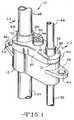
- FIG. 1is a perspective view of a first embodiment coupling assembly according to the present invention
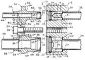
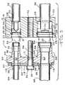
- FIG. 2is a cross-sectional view taken through the center of the first embodiment coupling assembly according to the present invention with the female body separated from the male coupling portion;
- FIG. 3is a view similar to the view of FIG. 2 showing the female body joined to the male coupling portion;
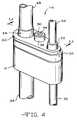
- FIG. 4is a perspective view of a second embodiment coupling assembly according to the present invention.
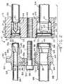
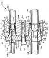
- FIG. 5is a cross-sectional view taken through the center of the second embodiment coupling assembly according to the present invention with the female body separated from the male coupling portion;
- FIG. 6is a view similar to the view of FIG. 5 showing the female body joined to the male coupling portion;
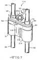
- FIG. 7is a perspective view of a third embodiment coupling assembly according to the present invention.
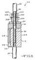
- FIG. 8is a cross-sectional view of the third embodiment coupling assembly according to the present invention showing the female body joined to the male coupling portion;
- FIG. 9is a perspective view of an alternative embodiment bracket according to the present invention.
- FIG. 10is a top view of the bracket shown in FIG. 9.
- FIG. 11is a cross-sectional view taken through the center of the bracket shown in FIG. 9 .
- the coupling assembly 10includes a unitary female body 12 formed of metal that includes at least two cylindrical passageways 14 and 16 .
- the passageways 14 and 16can either have different diameters as shown in FIG. 2 or identical diameters depending on the application.
- Each passageway 14 and 16includes a first end 18 and a second end 20 .
- An annular sealing edge 22is positioned adjacent to the first end 18 of each passageway 14 and 16 .
- An annular seal 24is positioned in an annular groove 25 formed in each passageway 14 and 16 adjacent to the first end 18 .
- a frangible metal female diaphragm 26is positioned in each passageway 14 and 16 adjacent to the annular seal 24 and has an annular sidewall 27 soldered or brazed to the inside surface of each passageway 14 and 16 . The end of the sidewall 27 engages a shoulder 29 in each passageway 14 and 16 .
- a metal cutting device 28 having a sharp edge 30is positioned in each passageway 14 and 16 adjacent to the female diaphragm 26 . The size and shape of the cutting device 28 is determined by the diameter of the passageway in which it is positioned.
- the cutting device 28has an annular flange 33 at the end opposite the cutting edge 30 which rests against a shoulder 31 of the female body 12 adjacent to each passageway 14 and 16 .
- a first line 32is positioned in the first passageway 14 adjacent to the second end 20 .
- a second line 34is positioned in the second passageway 16 adjacent to the second end 20 .
- the female body 12includes two mounting flanges 36 and 38 .
- Each of the mounting flanges 36 and 38includes an opening 40 for receiving, for example, a threaded bolt (not shown) to attach the female body 12 to, for example, an outside unit of a split-type air conditioning system (not shown).
- the female body 12includes a threaded opening 42 .
- the coupling assembly 10includes a male coupling portion 50 including a first male coupling half 52 and a separate second male coupling half 54 .
- the first and second coupling halves 52 and 54are formed of metal.
- Each coupling half 52 and 54includes a leading end 56 , a trailing end 58 and a cylindrical bore 60 extending between the leading and trailing ends 56 and 58 .
- the leading ends 56 of the first and second male coupling halves 52 and 54are sized and configured for insertion in the first ends 18 of the first and second passageways 14 and 16 , respectively.
- Each coupling half 52 and 54includes a frangible metal male diaphragm 62 positioned in the bore 60 adjacent to the leading end 56 .
- Each diaphragm 62has an annular sidewall 63 soldered or brazed to the inside surface of its respective bore 60 in the area adjacent to the leading end 56 .
- the end of the sidewall 63engages a shoulder 65 spaced from the leading end 56 .
- Each coupling half 52 and 54includes an annular sealing surface 64 sized and configured for engagement with a corresponding annular sealing edge 22 of the female body 12 .
- the first male coupling half 52includes a third line 66 positioned in the bore 60 adjacent to the trailing end 58 .
- the second male coupling half 54includes a fourth line 68 positioned in the bore 60 adjacent to the trailing end 58 .
- each coupling half 52 and 54includes an annular shoulder 70 .
- the coupling assembly 10includes a metal bracket 80 having a first recess 82 and a second recess 84 .
- the first recess 82receives the first male coupling half 52 and the second recess 84 receives the second male coupling half 54 .
- each recess 82 and 84includes a stop 86 that is sized and configured to receive a corresponding annular shoulder 70 of the first and second male coupling halves 52 and 54 .
- the bracket 80defines an opening 88 .
- the coupling assembly 10includes a threaded bolt 90 having a head 92 that defines a tool recess 94 .
- the bolt 90extends through the opening 88 and further includes a threaded portion 96 that is sized and configured to be received by the threaded opening 42 of the female body 12 .
- the intended use of the coupling assembly 1 0will be described.
- the first, second, third and fourth lines 32 , 34 , 66 and 68Prior to the connection of the female body 12 with the male coupling portion 50 , the first, second, third and fourth lines 32 , 34 , 66 and 68 , respectively, are precharged with refrigerant.
- the female and male diaphragms 26 and 62prevent the escape of refrigerant from the lines 32 , 34 , 66 and 68 .
- the female body 12is connected to the male coupling portion 50 by the insertion of the first and second male coupling halves 52 and 54 into the first ends 18 of the first and second passageways 14 and 16 , respectively.
- the bracket 80is positioned adjacent to the annular shoulders 70 of the first and second male coupling halves 52 and 54 .
- the bolt 90is inserted through the opening 88 of the bracket 80 and into the threaded opening 42 of the female body 12 .
- a tightening toolsuch as a wrench (not shown), is inserted into the tool recess 94 of the head 92 of the bolt 90 .
- the bolt 90is then torqued so that the threaded portion 96 of the bolt 90 engages the threaded opening 42 to draw the bracket 80 toward the female body 12 .
- the stops 86 of the bracket 80engage the annular shoulders 70 of the first and second male coupling halves 52 and 54 to cause them to be in axial alignment with the first and second passageways 14 and 16 .
- first and second male coupling halves 52 and 54are moved into the first and second passageways 14 and 16 , the sharp edges 30 of the cutting devices 28 of the female body 12 engage first the female diaphragms 26 and then the male diaphragms 62 to cause the diaphragms 26 and 62 to rupture or open and to fold away from the fluid flow path defined by the respective passageways 14 and 16 and bores 60 .
- thisallows the first and second passageways 14 and 16 of the female body 12 to be in fluid communication with the bores 60 of the first and second male coupling halves 52 and 54 . Accordingly, this allows for the movement of refrigerant through the first, second, third and fourth lines 32 , 34 , 66 and 68 , respectively.
- the bolt 90is torqued until the bracket 80 causes the annular sealing surfaces 64 of the first and second male coupling halves 52 and 54 to engage the corresponding annular sealing edges 22 of the female body 12 .
- Thisprovides “metal-to-metal” seals between the female body 12 and the first and second male coupling halves 52 and 54 .
- the annular seals 24maintain seals between the exterior surfaces 98 of the first and second male coupling halves 52 and 54 and the first and second passageways 14 and 16 of the female body 12 to prevent leakage of refrigerant during connection.
- a second embodiment coupling assembly 110is shown in FIGS. 4-6.
- the coupling assembly 110includes the elements described above with respect to the first embodiment coupling assembly 10 .
- the male coupling portion 50is unitary.
- the male coupling portion 50includes an opening 112 for receiving the bolt 90 .
- the bracket 80includes a first opening 114 and a second opening 116 that are sized and configured to receive the trailing ends 58 of the first and second coupling halves 52 and 54 .
- the bracket 80includes a center portion 118 that is bowed. As shown in FIG.
- the head 92 of the bolt 90engages the center portion 118 and forces it toward the male coupling portion 50 so that the bracket becomes flush with an exterior surface 120 of the male coupling portion 50 to equally distribute the clamping force on the male coupling portion 50 and to provide a visual indication that the bolt 90 has been properly torqued.
- a third embodiment coupling assembly 210is shown in FIGS. 7 and 8.
- the coupling assembly 210includes the elements described above with respect to the first embodiment coupling assembly 10 .
- the female body 12has a first side 212 and a second side 214 .
- the first side 212includes a recess 216 .
- the male coupling portion 50includes a projection 218 that is received by the recess 216 of the female body 12 . This ensures the proper alignment of the female body 12 with respect to the male coupling portion 50 .
- the coupling assembly 210further includes a frangible head 220 having an unthreaded top portion 222 and a threaded bottom portion 224 .
- the unthreaded top portion 222has an inwardly facing wall surface 223 spaced from the bolt 90 .
- An annular slot 226partially divides the top portion 222 from the bottom portion 224 .
- a washer 228is positioned in the slot 226 .
- the head 220has a predetermined torque value as determined by the depth of the slot 226 and the thickness of the metal between the radially innermost portion of the slot 226 and the wall surface 223 so that once the proper amount of torque has been applied to the head 220 , the top portion 222 breaks away from the bottom portion 224 .
- each recess 82 and 84includes a stop 86 that is sized and configured to receive a corresponding annular shoulder 70 of the first and second male coupling halves 52 and 54 .
- Each stop 86includes at least one raised portion 240 . In the embodiment shown in FIGS. 9-11, each stop 86 includes two raised portions 240 .
- the raised portions 240apply the clamping load of the bracket 80 at the centerline of the mating male coupling halves 52 and 54 and the first and second passageways 14 and 16 , respectively, to ensure a uniform seal between the respective annular sealing edges 22 and the annular sealing surfaces 64 as described above.
- the bracket 80defines an opening 88 for receiving a bolt 90 as described above.
Landscapes
- Engineering & Computer Science (AREA)
- General Engineering & Computer Science (AREA)
- Mechanical Engineering (AREA)
- Quick-Acting Or Multi-Walled Pipe Joints (AREA)
- Filling Or Discharging Of Gas Storage Vessels (AREA)
- Joints That Cut Off Fluids, And Hose Joints (AREA)
- Connection Of Plates (AREA)
Abstract
Description
Claims (12)
Priority Applications (1)
| Application Number | Priority Date | Filing Date | Title |
|---|---|---|---|
| US09/703,256US6481756B1 (en) | 1998-10-02 | 2000-10-31 | Coupling assembly |
Applications Claiming Priority (3)
| Application Number | Priority Date | Filing Date | Title |
|---|---|---|---|
| US10275198P | 1998-10-02 | 1998-10-02 | |
| US09/397,397US6382678B1 (en) | 1998-10-02 | 1999-09-16 | Coupling assembly |
| US09/703,256US6481756B1 (en) | 1998-10-02 | 2000-10-31 | Coupling assembly |
Related Parent Applications (1)
| Application Number | Title | Priority Date | Filing Date |
|---|---|---|---|
| US09/397,397Continuation-In-PartUS6382678B1 (en) | 1998-10-02 | 1999-09-16 | Coupling assembly |
Publications (1)
| Publication Number | Publication Date |
|---|---|
| US6481756B1true US6481756B1 (en) | 2002-11-19 |
Family
ID=26799694
Family Applications (1)
| Application Number | Title | Priority Date | Filing Date |
|---|---|---|---|
| US09/703,256Expired - LifetimeUS6481756B1 (en) | 1998-10-02 | 2000-10-31 | Coupling assembly |
Country Status (8)
| Country | Link |
|---|---|
| US (1) | US6481756B1 (en) |
| EP (1) | EP1117959B1 (en) |
| JP (1) | JP2002526736A (en) |
| CN (1) | CN1321232A (en) |
| AU (1) | AU6154699A (en) |
| DE (1) | DE69936591T2 (en) |
| EG (1) | EG21943A (en) |
| WO (1) | WO2000020792A1 (en) |
Cited By (42)
| Publication number | Priority date | Publication date | Assignee | Title |
|---|---|---|---|---|
| US20030214130A1 (en)* | 2002-05-20 | 2003-11-20 | Schroeder Fred Georg | Air conditioning block fitting with two surface sealing |
| US20040045646A1 (en)* | 2000-10-18 | 2004-03-11 | Friedhelm Kuehn | Method and device for annealing tubes |
| US20050017503A1 (en)* | 2003-07-23 | 2005-01-27 | Garry Tsaur | Connector with frangible seal |
| US20050023827A1 (en)* | 2003-08-01 | 2005-02-03 | Paccar Inc | Conduit coupling assembly |
| US20060001261A1 (en)* | 2004-06-30 | 2006-01-05 | Atsuo Miyajima | Through-panel fixing device for piping member |
| US20060137367A1 (en)* | 2004-12-27 | 2006-06-29 | Carrier Corporation | Dual thermochromic liquid crystal temperature sensing for refrigerant charge indication |
| US20060137366A1 (en)* | 2004-12-27 | 2006-06-29 | Carrier Corporation | Automatic refrigerant charging apparatus |
| US20060138771A1 (en)* | 2004-12-27 | 2006-06-29 | Carrier Corporation | Braze-free connector for joining a pair of flow lines |
| US20060138772A1 (en)* | 2004-12-27 | 2006-06-29 | Carrier Corporation | Braze-free connector |
| US20060137369A1 (en)* | 2004-12-27 | 2006-06-29 | Carrier Corporation | Single sensor three-step refrigerant charge indicator |
| US20070007764A1 (en)* | 2005-07-11 | 2007-01-11 | Simmons Tom M | Connections for tubing and method of connecting tubing segments |
| US20070107707A1 (en)* | 2005-11-16 | 2007-05-17 | Arnulf Spieth | Crosstalk device for an exhaust system |
| US20070222159A1 (en)* | 2006-02-17 | 2007-09-27 | Baxi Nikhil R | Composite seal and coupling |
| US20080007048A1 (en)* | 2005-07-13 | 2008-01-10 | Carrier Corporation | Braze-free connector utilizing a sealant coated ferrule |
| US20080217915A1 (en)* | 2005-03-04 | 2008-09-11 | Nils Arthun | Method and Device for Interconnecting, Sealed Against Contamination, the Ends of Elongate Elements Such as Tubes or Pipes |
| US20080224078A1 (en)* | 2007-03-12 | 2008-09-18 | Automatic Bar Control, Inc. | Modular Fittings and Assemblies for Fluid Switching |
| US20090028725A1 (en)* | 2007-07-26 | 2009-01-29 | Samsung Electronics Co., Ltd. | Hermetic compressor |
| US20090140515A1 (en)* | 2006-05-25 | 2009-06-04 | Calsonic Kansei Corporation | Pipe connector |
| US7610765B2 (en) | 2004-12-27 | 2009-11-03 | Carrier Corporation | Refrigerant charge status indication method and device |
| US20100089076A1 (en)* | 2006-12-20 | 2010-04-15 | Carrier Corproation | Refrigerant charge indication |
| US7712319B2 (en) | 2004-12-27 | 2010-05-11 | Carrier Corporation | Refrigerant charge adequacy gauge |
| US7753338B2 (en) | 2006-10-23 | 2010-07-13 | Baxter International Inc. | Luer activated device with minimal fluid displacement |
| US7981090B2 (en) | 2006-10-18 | 2011-07-19 | Baxter International Inc. | Luer activated device |
| US8221363B2 (en) | 2006-10-18 | 2012-07-17 | Baxter Healthcare S.A. | Luer activated device with valve element under tension |
| US8290722B2 (en) | 2006-12-20 | 2012-10-16 | Carrier Corporation | Method for determining refrigerant charge |
| WO2012170961A1 (en)* | 2011-06-08 | 2012-12-13 | Nxstage Medical, Inc. | Methods, devices, and systems for coupling fluid lines |
| US20140038757A1 (en)* | 2012-08-03 | 2014-02-06 | Shimano Inc. | Hydraulic bicycle component |
| US8820351B1 (en)* | 2013-06-25 | 2014-09-02 | Chilldyne, Inc. | No drip hot swap connector and method of use |
| US9199691B2 (en) | 2012-08-03 | 2015-12-01 | Shimano Inc. | Hydraulic bicycle component kit |
| US9227692B2 (en) | 2012-08-03 | 2016-01-05 | Shimano Inc. | Hydraulic bicycle component system |
| US9550546B2 (en)* | 2012-08-03 | 2017-01-24 | Shimano Inc. | Hydraulic bicycle hose structure |
| WO2017121818A1 (en)* | 2016-01-15 | 2017-07-20 | Ti Automotive Engineering Centre (Heidelberg) Gmbh | Connection arrangement for an air conditioning system and mobile air conditioning system |
| US20170217533A1 (en)* | 2016-02-01 | 2017-08-03 | Shimano Inc. | Non-metallic bracket for a bicycle hydraulic component |
| US9759465B2 (en) | 2011-12-27 | 2017-09-12 | Carrier Corporation | Air conditioner self-charging and charge monitoring system |
| US9777878B2 (en) | 2012-08-31 | 2017-10-03 | Hanon Systems | Connector |
| US20180017193A1 (en)* | 2016-07-18 | 2018-01-18 | Nissan North America, Inc. | Seal member for a hydraulic fluid actuator |
| US10077611B2 (en)* | 2013-09-02 | 2018-09-18 | Aborra Ag | Fracturing tube system |
| US10164373B1 (en)* | 2013-03-15 | 2018-12-25 | Koolance, Inc. | Automatic engagement system for liquid or power connections |
| US20210002866A1 (en)* | 2019-07-02 | 2021-01-07 | Bomag Gmbh | Fitting securing device for hydraulic hose couplings, construction machine, and method |
| US12135104B2 (en) | 2019-04-09 | 2024-11-05 | Nxstage Medical, Inc. | Methods, devices, and systems for coupling fluid lines |
| US12196342B2 (en) | 2019-09-12 | 2025-01-14 | A. Raymond Et Cie | Flow control valve and system for cleaning a vehicle surface |
| US12202446B2 (en) | 2019-09-12 | 2025-01-21 | A. Raymond Et Cie | Flow control valve and system for cleaning a vehicle surface |
Families Citing this family (10)
| Publication number | Priority date | Publication date | Assignee | Title |
|---|---|---|---|---|
| GB2382391B (en)* | 2001-11-01 | 2004-10-13 | Visteon Global Tech Inc | Peanut fittings for CO2 air conditioning systems |
| US6834893B2 (en) | 2001-11-01 | 2004-12-28 | Visteon Global Technologies, Inc. | Peanut fittings for CO2 air conditioning systems |
| FR2933155B1 (en)* | 2008-06-30 | 2010-08-27 | Staubli Sa Ets | CONNECTION ASSEMBLY AND METHOD FOR CONNECTING SUCH AN ASSEMBLY |
| US8833803B2 (en)* | 2011-03-31 | 2014-09-16 | Denso International America, Inc. | Connecting block |
| US10544890B2 (en)* | 2015-07-01 | 2020-01-28 | Denso Corporation | Pair of connectors |
| CN107387918A (en)* | 2017-07-21 | 2017-11-24 | 珠海格力电器股份有限公司 | Connection structure of filter element group spare and water route board reaches purifier including it |
| DE102017222604A1 (en) | 2017-12-13 | 2019-06-13 | Bayerische Motoren Werke Aktiengesellschaft | Plug connection, method for producing a line arrangement and cooling system |
| CN108561653A (en)* | 2018-06-27 | 2018-09-21 | 绵阳创格科技有限公司 | A kind of Multichannel device of fast assembling-disassembling |
| JP2020055194A (en)* | 2018-10-01 | 2020-04-09 | セイコーエプソン株式会社 | Liquid ejection device |
| GB2612089B (en)* | 2021-10-21 | 2024-10-30 | Mark Vince Fenson | Pipe interconnector |
Citations (25)
| Publication number | Priority date | Publication date | Assignee | Title |
|---|---|---|---|---|
| US3202442A (en) | 1961-05-19 | 1965-08-24 | Aeroquip Corp | Coupling |
| FR1423028A (en) | 1964-11-17 | 1966-01-03 | Pierre Cibie | Advanced connection set, especially for hydraulic circuits |
| US3844585A (en) | 1973-07-10 | 1974-10-29 | Mueller Co | Pipe coupling |
| US3874710A (en) | 1972-11-02 | 1975-04-01 | Weatherhead Co | Tubing manifold coupling |
| US3929356A (en) | 1974-11-13 | 1975-12-30 | Gen Motors Corp | Tube to block mounting assembly |
| US3978761A (en)* | 1975-06-26 | 1976-09-07 | Thomas & Betts Corporation | Fastener assembly |
| US4019512A (en)* | 1975-12-04 | 1977-04-26 | Tenczar Francis J | Adhesively activated sterile connector |
| US4022496A (en) | 1975-03-31 | 1977-05-10 | Aeroquip Corporation | Frangible diaphragm refrigeration coupling |
| US4029379A (en)* | 1973-09-14 | 1977-06-14 | Westinghouse Electric Corporation | Electrical bus duct with torque indication nut |
| US4290276A (en) | 1979-11-01 | 1981-09-22 | Aeroquip Corporation | Valve with frangible closure |
| US4468054A (en)* | 1982-11-03 | 1984-08-28 | The Singer Company | Flange mounted thermostatic expansion valve |
| US5092797A (en) | 1991-07-08 | 1992-03-03 | Amp Incorporated | Electrical wire connector |
| US5294156A (en) | 1991-02-20 | 1994-03-15 | Nippondenso Co., Ltd. | Flange coupling for connecting pipes for carrying refrigerant during refrigerating cycle |
| US5323808A (en) | 1992-06-15 | 1994-06-28 | Sanden Corporation | Refrigerant charge connecting unit |
| US5338075A (en) | 1993-06-03 | 1994-08-16 | Albrecht David E | Combination fluid flow ports |
| US5354101A (en) | 1993-09-13 | 1994-10-11 | General Motors Corporation | Sealing washer block connection |
| US5354103A (en)* | 1994-01-28 | 1994-10-11 | Eaton Corporation | Quick connect conduit coupling |
| DE4432562A1 (en) | 1993-10-22 | 1995-04-27 | Automotive Fluid Systems Inc | Quick-connect swivel coupling |
| EP0657680A2 (en) | 1993-12-06 | 1995-06-14 | Ford Motor Company | Tube coupling block |
| US5464042A (en) | 1994-04-29 | 1995-11-07 | Aeroquip Corporation | Quick connect air-conditioning coupling |
| US5467611A (en) | 1994-11-07 | 1995-11-21 | General Motors Corporation | Two plate TXV block connector for automotive A/C system with common bolts and independently attachable sides |
| US5492147A (en)* | 1995-01-17 | 1996-02-20 | Aeroquip Corporation | Dry break coupling |
| WO1997014893A1 (en) | 1995-10-20 | 1997-04-24 | Moonlight Security Ab | Screw bolt |
| US6234538B1 (en)* | 1998-06-26 | 2001-05-22 | Fresenius Medical Care Deutschland Gmbh | Connector element |
| US6382678B1 (en)* | 1998-10-02 | 2002-05-07 | Parker-Hannifin Corporation | Coupling assembly |
- 1999
- 1999-09-22EPEP99948343Apatent/EP1117959B1/ennot_activeExpired - Lifetime
- 1999-09-22DEDE69936591Tpatent/DE69936591T2/ennot_activeExpired - Lifetime
- 1999-09-22WOPCT/US1999/021730patent/WO2000020792A1/enactiveIP Right Grant
- 1999-09-22JPJP2000574867Apatent/JP2002526736A/enactivePending
- 1999-09-22AUAU61546/99Apatent/AU6154699A/ennot_activeAbandoned
- 1999-09-22CNCN99811696Apatent/CN1321232A/enactivePending
- 1999-09-30EGEG122199Apatent/EG21943A/enactive
- 2000
- 2000-10-31USUS09/703,256patent/US6481756B1/ennot_activeExpired - Lifetime
Patent Citations (25)
| Publication number | Priority date | Publication date | Assignee | Title |
|---|---|---|---|---|
| US3202442A (en) | 1961-05-19 | 1965-08-24 | Aeroquip Corp | Coupling |
| FR1423028A (en) | 1964-11-17 | 1966-01-03 | Pierre Cibie | Advanced connection set, especially for hydraulic circuits |
| US3874710A (en) | 1972-11-02 | 1975-04-01 | Weatherhead Co | Tubing manifold coupling |
| US3844585A (en) | 1973-07-10 | 1974-10-29 | Mueller Co | Pipe coupling |
| US4029379A (en)* | 1973-09-14 | 1977-06-14 | Westinghouse Electric Corporation | Electrical bus duct with torque indication nut |
| US3929356A (en) | 1974-11-13 | 1975-12-30 | Gen Motors Corp | Tube to block mounting assembly |
| US4022496A (en) | 1975-03-31 | 1977-05-10 | Aeroquip Corporation | Frangible diaphragm refrigeration coupling |
| US3978761A (en)* | 1975-06-26 | 1976-09-07 | Thomas & Betts Corporation | Fastener assembly |
| US4019512A (en)* | 1975-12-04 | 1977-04-26 | Tenczar Francis J | Adhesively activated sterile connector |
| US4290276A (en) | 1979-11-01 | 1981-09-22 | Aeroquip Corporation | Valve with frangible closure |
| US4468054A (en)* | 1982-11-03 | 1984-08-28 | The Singer Company | Flange mounted thermostatic expansion valve |
| US5294156A (en) | 1991-02-20 | 1994-03-15 | Nippondenso Co., Ltd. | Flange coupling for connecting pipes for carrying refrigerant during refrigerating cycle |
| US5092797A (en) | 1991-07-08 | 1992-03-03 | Amp Incorporated | Electrical wire connector |
| US5323808A (en) | 1992-06-15 | 1994-06-28 | Sanden Corporation | Refrigerant charge connecting unit |
| US5338075A (en) | 1993-06-03 | 1994-08-16 | Albrecht David E | Combination fluid flow ports |
| US5354101A (en) | 1993-09-13 | 1994-10-11 | General Motors Corporation | Sealing washer block connection |
| DE4432562A1 (en) | 1993-10-22 | 1995-04-27 | Automotive Fluid Systems Inc | Quick-connect swivel coupling |
| EP0657680A2 (en) | 1993-12-06 | 1995-06-14 | Ford Motor Company | Tube coupling block |
| US5354103A (en)* | 1994-01-28 | 1994-10-11 | Eaton Corporation | Quick connect conduit coupling |
| US5464042A (en) | 1994-04-29 | 1995-11-07 | Aeroquip Corporation | Quick connect air-conditioning coupling |
| US5467611A (en) | 1994-11-07 | 1995-11-21 | General Motors Corporation | Two plate TXV block connector for automotive A/C system with common bolts and independently attachable sides |
| US5492147A (en)* | 1995-01-17 | 1996-02-20 | Aeroquip Corporation | Dry break coupling |
| WO1997014893A1 (en) | 1995-10-20 | 1997-04-24 | Moonlight Security Ab | Screw bolt |
| US6234538B1 (en)* | 1998-06-26 | 2001-05-22 | Fresenius Medical Care Deutschland Gmbh | Connector element |
| US6382678B1 (en)* | 1998-10-02 | 2002-05-07 | Parker-Hannifin Corporation | Coupling assembly |
Non-Patent Citations (2)
| Title |
|---|
| 5780 Series, quick Connect Precharging Refrigerant Couplings, Copyright 1992 Aeroquip Corporation, pp. 2-8. |
| Brochure entitled "ConnectAire" (TM) Aeroquip, undated. |
Cited By (67)
| Publication number | Priority date | Publication date | Assignee | Title |
|---|---|---|---|---|
| US20040045646A1 (en)* | 2000-10-18 | 2004-03-11 | Friedhelm Kuehn | Method and device for annealing tubes |
| US20030214130A1 (en)* | 2002-05-20 | 2003-11-20 | Schroeder Fred Georg | Air conditioning block fitting with two surface sealing |
| US6676167B2 (en)* | 2002-05-20 | 2004-01-13 | Visteon Global Technologies, Inc. | Air conditioning block fitting with two surface sealing |
| US20040080159A1 (en)* | 2002-05-20 | 2004-04-29 | Schroeder Fred Georg | Air conditioning block fitting with two surface sealing |
| US6869107B2 (en) | 2002-05-20 | 2005-03-22 | Visteon Global Technologies, Inc. | Air conditioning block fitting with two surface sealing |
| US20050017503A1 (en)* | 2003-07-23 | 2005-01-27 | Garry Tsaur | Connector with frangible seal |
| US20050023827A1 (en)* | 2003-08-01 | 2005-02-03 | Paccar Inc | Conduit coupling assembly |
| US6896298B2 (en) | 2003-08-01 | 2005-05-24 | Paccar Inc | Conduit coupling assembly |
| US20060001261A1 (en)* | 2004-06-30 | 2006-01-05 | Atsuo Miyajima | Through-panel fixing device for piping member |
| US7464966B2 (en)* | 2004-06-30 | 2008-12-16 | Tokai Rubber Industries, Inc. | Through-panel fixing device for piping member |
| US20060138772A1 (en)* | 2004-12-27 | 2006-06-29 | Carrier Corporation | Braze-free connector |
| US20060137367A1 (en)* | 2004-12-27 | 2006-06-29 | Carrier Corporation | Dual thermochromic liquid crystal temperature sensing for refrigerant charge indication |
| US7552596B2 (en) | 2004-12-27 | 2009-06-30 | Carrier Corporation | Dual thermochromic liquid crystal temperature sensing for refrigerant charge indication |
| US20060137369A1 (en)* | 2004-12-27 | 2006-06-29 | Carrier Corporation | Single sensor three-step refrigerant charge indicator |
| US20060138771A1 (en)* | 2004-12-27 | 2006-06-29 | Carrier Corporation | Braze-free connector for joining a pair of flow lines |
| US20060137366A1 (en)* | 2004-12-27 | 2006-06-29 | Carrier Corporation | Automatic refrigerant charging apparatus |
| US7610765B2 (en) | 2004-12-27 | 2009-11-03 | Carrier Corporation | Refrigerant charge status indication method and device |
| US7472557B2 (en) | 2004-12-27 | 2009-01-06 | Carrier Corporation | Automatic refrigerant charging apparatus |
| US7712319B2 (en) | 2004-12-27 | 2010-05-11 | Carrier Corporation | Refrigerant charge adequacy gauge |
| US7922211B2 (en)* | 2005-03-04 | 2011-04-12 | Millipore Ab | Method and device for interconnecting, sealed against contamination, the ends of elongate elements such as tubes or pipes |
| US20080217915A1 (en)* | 2005-03-04 | 2008-09-11 | Nils Arthun | Method and Device for Interconnecting, Sealed Against Contamination, the Ends of Elongate Elements Such as Tubes or Pipes |
| US20070007764A1 (en)* | 2005-07-11 | 2007-01-11 | Simmons Tom M | Connections for tubing and method of connecting tubing segments |
| US7591485B2 (en)* | 2005-07-11 | 2009-09-22 | Simmons Tom M | Connections for tubing and method of connecting tubing segments |
| US7419192B2 (en) | 2005-07-13 | 2008-09-02 | Carrier Corporation | Braze-free connector utilizing a sealant coated ferrule |
| US20080007048A1 (en)* | 2005-07-13 | 2008-01-10 | Carrier Corporation | Braze-free connector utilizing a sealant coated ferrule |
| US7866709B2 (en)* | 2005-11-16 | 2011-01-11 | J. Eberspaecher Gmbh & Co. Kg | Crosstalk device for an exhaust system |
| US20070107707A1 (en)* | 2005-11-16 | 2007-05-17 | Arnulf Spieth | Crosstalk device for an exhaust system |
| US20070222159A1 (en)* | 2006-02-17 | 2007-09-27 | Baxi Nikhil R | Composite seal and coupling |
| US8186691B2 (en) | 2006-02-17 | 2012-05-29 | Parker-Hannifin Corporation | Composite seal and coupling |
| US20090140515A1 (en)* | 2006-05-25 | 2009-06-04 | Calsonic Kansei Corporation | Pipe connector |
| US7981090B2 (en) | 2006-10-18 | 2011-07-19 | Baxter International Inc. | Luer activated device |
| US8221363B2 (en) | 2006-10-18 | 2012-07-17 | Baxter Healthcare S.A. | Luer activated device with valve element under tension |
| US7753338B2 (en) | 2006-10-23 | 2010-07-13 | Baxter International Inc. | Luer activated device with minimal fluid displacement |
| US9568226B2 (en) | 2006-12-20 | 2017-02-14 | Carrier Corporation | Refrigerant charge indication |
| US20100089076A1 (en)* | 2006-12-20 | 2010-04-15 | Carrier Corproation | Refrigerant charge indication |
| US8290722B2 (en) | 2006-12-20 | 2012-10-16 | Carrier Corporation | Method for determining refrigerant charge |
| US8251087B2 (en)* | 2007-03-12 | 2012-08-28 | Automatic Bar Controls, Inc. | Modular fittings and assemblies for fluid switching |
| US20080224078A1 (en)* | 2007-03-12 | 2008-09-18 | Automatic Bar Control, Inc. | Modular Fittings and Assemblies for Fluid Switching |
| US8529224B2 (en)* | 2007-07-26 | 2013-09-10 | Samsung Electronics Co., Ltd. | Hermetic compressor having auxiliary communication tube |
| US20090028725A1 (en)* | 2007-07-26 | 2009-01-29 | Samsung Electronics Co., Ltd. | Hermetic compressor |
| WO2012170961A1 (en)* | 2011-06-08 | 2012-12-13 | Nxstage Medical, Inc. | Methods, devices, and systems for coupling fluid lines |
| US10895339B2 (en) | 2011-06-08 | 2021-01-19 | Nxstage Medical, Inc. | Methods, devices, and systems for coupling fluid lines |
| GB2505132A (en)* | 2011-06-08 | 2014-02-19 | Nxstage Medical Inc | Methods, devices, and systems for coupling fluid lines |
| US10221975B2 (en) | 2011-06-08 | 2019-03-05 | Nxstage Medical, Inc. | Methods, devices, and systems for coupling fluid lines |
| US9879807B2 (en) | 2011-06-08 | 2018-01-30 | Nxstage Medical, Inc. | Methods, devices, and systems for coupling fluid lines |
| US9759465B2 (en) | 2011-12-27 | 2017-09-12 | Carrier Corporation | Air conditioner self-charging and charge monitoring system |
| US9550546B2 (en)* | 2012-08-03 | 2017-01-24 | Shimano Inc. | Hydraulic bicycle hose structure |
| US10131339B2 (en)* | 2012-08-03 | 2018-11-20 | Shimano Inc. | Hydraulic bicycle component |
| US20140038757A1 (en)* | 2012-08-03 | 2014-02-06 | Shimano Inc. | Hydraulic bicycle component |
| US9199691B2 (en) | 2012-08-03 | 2015-12-01 | Shimano Inc. | Hydraulic bicycle component kit |
| US10272895B2 (en) | 2012-08-03 | 2019-04-30 | Shimano Inc. | Hydraulic bicycle component |
| US9227692B2 (en) | 2012-08-03 | 2016-01-05 | Shimano Inc. | Hydraulic bicycle component system |
| US10495247B2 (en) | 2012-08-31 | 2019-12-03 | Hanon Systems | Connector |
| US9777878B2 (en) | 2012-08-31 | 2017-10-03 | Hanon Systems | Connector |
| US10164373B1 (en)* | 2013-03-15 | 2018-12-25 | Koolance, Inc. | Automatic engagement system for liquid or power connections |
| US20140373933A1 (en)* | 2013-06-25 | 2014-12-25 | Chilldyne, Inc. | No Drip Hot Swap Connector And Method of Use |
| US8820351B1 (en)* | 2013-06-25 | 2014-09-02 | Chilldyne, Inc. | No drip hot swap connector and method of use |
| US10077611B2 (en)* | 2013-09-02 | 2018-09-18 | Aborra Ag | Fracturing tube system |
| WO2017121818A1 (en)* | 2016-01-15 | 2017-07-20 | Ti Automotive Engineering Centre (Heidelberg) Gmbh | Connection arrangement for an air conditioning system and mobile air conditioning system |
| US9963192B2 (en)* | 2016-02-01 | 2018-05-08 | Shimano Inc. | Non-metallic bracket for a bicycle hydraulic component |
| US20170217533A1 (en)* | 2016-02-01 | 2017-08-03 | Shimano Inc. | Non-metallic bracket for a bicycle hydraulic component |
| US20180017193A1 (en)* | 2016-07-18 | 2018-01-18 | Nissan North America, Inc. | Seal member for a hydraulic fluid actuator |
| US11353145B2 (en)* | 2016-07-18 | 2022-06-07 | Nissan North America, Inc. | Seal member for a hydraulic fluid actuator |
| US12135104B2 (en) | 2019-04-09 | 2024-11-05 | Nxstage Medical, Inc. | Methods, devices, and systems for coupling fluid lines |
| US20210002866A1 (en)* | 2019-07-02 | 2021-01-07 | Bomag Gmbh | Fitting securing device for hydraulic hose couplings, construction machine, and method |
| US12196342B2 (en) | 2019-09-12 | 2025-01-14 | A. Raymond Et Cie | Flow control valve and system for cleaning a vehicle surface |
| US12202446B2 (en) | 2019-09-12 | 2025-01-21 | A. Raymond Et Cie | Flow control valve and system for cleaning a vehicle surface |
Also Published As
| Publication number | Publication date |
|---|---|
| WO2000020792A1 (en) | 2000-04-13 |
| EG21943A (en) | 2002-04-30 |
| AU6154699A (en) | 2000-04-26 |
| DE69936591T2 (en) | 2008-02-14 |
| EP1117959B1 (en) | 2007-07-18 |
| CN1321232A (en) | 2001-11-07 |
| JP2002526736A (en) | 2002-08-20 |
| DE69936591D1 (en) | 2007-08-30 |
| EP1117959A1 (en) | 2001-07-25 |
Similar Documents
| Publication | Publication Date | Title |
|---|---|---|
| US6481756B1 (en) | Coupling assembly | |
| US6382678B1 (en) | Coupling assembly | |
| US6869107B2 (en) | Air conditioning block fitting with two surface sealing | |
| US7032934B2 (en) | Hydraulic fitting | |
| US4640534A (en) | Fluid coupling assembly | |
| EP0756119B1 (en) | Hydraulic port fittings | |
| US4712812A (en) | Universal fittings | |
| US5328215A (en) | Pipe joint assembly | |
| US3930674A (en) | Couplings | |
| US5374084A (en) | Coupling for automobile air conditioning system | |
| US4428603A (en) | Flange union with improved metal-to-metal seals | |
| EP0857273B1 (en) | Flow line coupling | |
| US5156421A (en) | Fluid-tight connectors for fluid-carrying pipe-lines | |
| US4653724A (en) | Universal type butterfly valve and manufacturing process for same | |
| EP0177116A1 (en) | Adapter seal | |
| AU660129B1 (en) | Quick connect swivel coupling | |
| US20080048440A1 (en) | Direct port connection for tubes | |
| EP3885623B1 (en) | A reversible brake tube connector | |
| US1858136A (en) | Coupling | |
| JPS58502061A (en) | A fitting that joins a pipe with a flared end to a fixed coupling part, such as a pump. | |
| US5076616A (en) | Hydraulic fitting with O-ring seal end stop | |
| US6019558A (en) | Nut and bolt securing device | |
| US20040124386A1 (en) | Lateral reducing valve | |
| US20030197378A1 (en) | Sealing compression ferrule for plumbing connection fitting | |
| US4610466A (en) | Convertible flare/braze fitting |
Legal Events
| Date | Code | Title | Description |
|---|---|---|---|
| AS | Assignment | Owner name:EATON AEROQUIP INC., OHIO Free format text:ASSIGNMENT OF ASSIGNORS INTEREST;ASSIGNORS:FIELD, JOHN C.;STEMMLER, JOHN C.;WELLS, MICHAEL P.;AND OTHERS;REEL/FRAME:011539/0493 Effective date:20010207 | |
| AS | Assignment | Owner name:EATON AC&R, LTD., OHIO Free format text:ASSIGNMENT OF ASSIGNORS INTEREST;ASSIGNOR:EATON AC&R, INC.;REEL/FRAME:012475/0895 Effective date:20010727 Owner name:EATON AC&R, INC., OHIO Free format text:ASSIGNMENT OF ASSIGNORS INTEREST;ASSIGNOR:EATON AEROQUIP, INC.;REEL/FRAME:012483/0457 Effective date:20010727 Owner name:EATON AC&R, LTD., OHIO Free format text:ASSIGNMENT OF ASSIGNORS INTEREST;ASSIGNOR:EATON AEROQUIP, INC.;REEL/FRAME:012483/0464 Effective date:20010727 Owner name:PARKER-HANNIFIN CORPORATION, OHIO Free format text:ASSIGNMENT OF ASSIGNORS INTEREST;ASSIGNOR:EATON AC&R, LTD.;REEL/FRAME:012483/0473 Effective date:20010831 | |
| AS | Assignment | Owner name:EATON AC&R, LTD., OHIO Free format text:ASSIGNMENT OF ASSIGNORS INTEREST;ASSIGNOR:EATON AEROQUIP, INC.;REEL/FRAME:012598/0174 Effective date:20010727 | |
| AS | Assignment | Owner name:PARKER-HANNIFIN CORPORATION, OHIO Free format text:ASSIGNMENT OF ASSIGNORS INTEREST;ASSIGNOR:EATON AC&R, LTD.;REEL/FRAME:012635/0011 Effective date:20020117 Owner name:EATON AC&R, LTD. LIMITED PARTNERSHIP, OHIO Free format text:ASSIGNMENT OF ASSIGNORS INTEREST;ASSIGNOR:EATON AC&R, INC.;REEL/FRAME:012635/0030 Effective date:20020117 Owner name:EATON AC&R, LTD., LIMITED PARTNERSHIP, OHIO Free format text:ASSIGNMENT OF ASSIGNORS INTEREST;ASSIGNOR:EATON AEROQUIP, INC.;REEL/FRAME:012635/0034 Effective date:20020117 Owner name:EATON AC&R, INC., OHIO Free format text:ASSIGNMENT OF ASSIGNORS INTEREST;ASSIGNOR:EATON AEROQUIP, INC.;REEL/FRAME:012637/0083 Effective date:20020117 | |
| STCF | Information on status: patent grant | Free format text:PATENTED CASE | |
| AS | Assignment | Owner name:PARKER HANNIFIN CUSTOMER SUPPORT INC., CALIFORNIA Free format text:ASSIGNMENT OF ASSIGNORS INTEREST;ASSIGNOR:PARKER-HANNIFIN CORPORATION;REEL/FRAME:014051/0030 Effective date:20030331 Owner name:PARKER HANNIFIN CUSTOMER SUPPORT INC.,CALIFORNIA Free format text:ASSIGNMENT OF ASSIGNORS INTEREST;ASSIGNOR:PARKER-HANNIFIN CORPORATION;REEL/FRAME:014051/0030 Effective date:20030331 | |
| AS | Assignment | Owner name:PARKER INTANGIBLES LLC, OHIO Free format text:MERGER;ASSIGNOR:PARKER HANNIFIN CUSTOMER SUPPORT INC.;REEL/FRAME:015215/0522 Effective date:20030630 | |
| FEPP | Fee payment procedure | Free format text:PAYOR NUMBER ASSIGNED (ORIGINAL EVENT CODE: ASPN); ENTITY STATUS OF PATENT OWNER: LARGE ENTITY | |
| FPAY | Fee payment | Year of fee payment:4 | |
| FEPP | Fee payment procedure | Free format text:PAYER NUMBER DE-ASSIGNED (ORIGINAL EVENT CODE: RMPN); ENTITY STATUS OF PATENT OWNER: LARGE ENTITY Free format text:PAYOR NUMBER ASSIGNED (ORIGINAL EVENT CODE: ASPN); ENTITY STATUS OF PATENT OWNER: LARGE ENTITY | |
| FPAY | Fee payment | Year of fee payment:8 | |
| FPAY | Fee payment | Year of fee payment:12 |