US6481239B2 - Insulated container and receptacle therefor - Google Patents
Insulated container and receptacle thereforDownload PDFInfo
- Publication number
- US6481239B2 US6481239B2US10/023,325US2332501AUS6481239B2US 6481239 B2US6481239 B2US 6481239B2US 2332501 AUS2332501 AUS 2332501AUS 6481239 B2US6481239 B2US 6481239B2
- Authority
- US
- United States
- Prior art keywords
- receptacle
- container
- insulated
- wall
- sidewall
- Prior art date
- Legal status (The legal status is an assumption and is not a legal conclusion. Google has not performed a legal analysis and makes no representation as to the accuracy of the status listed.)
- Expired - Lifetime
Links
- 239000012528membraneSubstances0.000claimsdescription4
- 239000000463materialSubstances0.000description25
- 238000001816coolingMethods0.000description23
- 238000003860storageMethods0.000description21
- 238000012546transferMethods0.000description17
- 230000013011matingEffects0.000description14
- 235000013361beverageNutrition0.000description13
- 239000004744fabricSubstances0.000description12
- 238000010276constructionMethods0.000description10
- 125000000391vinyl groupChemical group[H]C([*])=C([H])[H]0.000description9
- 229920002554vinyl polymerPolymers0.000description9
- 229920000642polymerPolymers0.000description8
- 239000006260foamSubstances0.000description7
- 235000013305foodNutrition0.000description7
- XLYOFNOQVPJJNP-UHFFFAOYSA-NwaterSubstancesOXLYOFNOQVPJJNP-UHFFFAOYSA-N0.000description7
- 230000000712assemblyEffects0.000description6
- 238000000429assemblyMethods0.000description6
- 230000004888barrier functionEffects0.000description6
- 230000008901benefitEffects0.000description5
- 238000010438heat treatmentMethods0.000description5
- 239000004677NylonSubstances0.000description4
- 230000000694effectsEffects0.000description4
- 229920001971elastomerPolymers0.000description4
- 229920001778nylonPolymers0.000description4
- 206010039509ScabDiseases0.000description3
- CDBYLPFSWZWCQE-UHFFFAOYSA-LSodium CarbonateChemical compound[Na+].[Na+].[O-]C([O-])=OCDBYLPFSWZWCQE-UHFFFAOYSA-L0.000description3
- 235000013405beerNutrition0.000description3
- 235000020965cold beverageNutrition0.000description3
- 238000007710freezingMethods0.000description3
- 230000008014freezingEffects0.000description3
- 230000002093peripheral effectEffects0.000description3
- 229920003023plasticPolymers0.000description3
- 239000004033plasticSubstances0.000description3
- 229920001084poly(chloroprene)Polymers0.000description3
- 239000005060rubberSubstances0.000description3
- 229920003051synthetic elastomerPolymers0.000description3
- 239000005061synthetic rubberSubstances0.000description3
- 238000005406washingMethods0.000description3
- 238000007792additionMethods0.000description2
- 229910052782aluminiumInorganic materials0.000description2
- XAGFODPZIPBFFR-UHFFFAOYSA-NaluminiumChemical compound[Al]XAGFODPZIPBFFR-UHFFFAOYSA-N0.000description2
- 238000013459approachMethods0.000description2
- -1booksSubstances0.000description2
- 239000011449brickSubstances0.000description2
- 238000009826distributionMethods0.000description2
- 238000001035dryingMethods0.000description2
- 235000013399edible fruitsNutrition0.000description2
- 235000011389fruit/vegetable juiceNutrition0.000description2
- 239000011521glassSubstances0.000description2
- 238000003780insertionMethods0.000description2
- 230000037431insertionEffects0.000description2
- 238000009413insulationMethods0.000description2
- 239000007788liquidSubstances0.000description2
- 230000033001locomotionEffects0.000description2
- 229910052751metalInorganic materials0.000description2
- 239000002184metalSubstances0.000description2
- 230000001681protective effectEffects0.000description2
- 238000007493shaping processMethods0.000description2
- 235000014214soft drinkNutrition0.000description2
- 229910001220stainless steelInorganic materials0.000description2
- 239000010935stainless steelSubstances0.000description2
- 229910001369BrassInorganic materials0.000description1
- 241000233866FungiSpecies0.000description1
- 240000008790Musa x paradisiacaSpecies0.000description1
- 241000238367Mya arenariaSpecies0.000description1
- 244000269722Thea sinensisSpecies0.000description1
- 230000003466anti-cipated effectEffects0.000description1
- 239000004599antimicrobialSubstances0.000description1
- 235000021015bananasNutrition0.000description1
- 230000009286beneficial effectEffects0.000description1
- 239000010951brassSubstances0.000description1
- 235000014171carbonated beverageNutrition0.000description1
- 230000008859changeEffects0.000description1
- 235000013351cheeseNutrition0.000description1
- 238000004140cleaningMethods0.000description1
- 235000016213coffeeNutrition0.000description1
- 235000013353coffee beverageNutrition0.000description1
- 235000021270cold foodNutrition0.000description1
- 230000006835compressionEffects0.000description1
- 238000007906compressionMethods0.000description1
- 235000009508confectioneryNutrition0.000description1
- 230000035622drinkingEffects0.000description1
- 230000009977dual effectEffects0.000description1
- 239000000806elastomerSubstances0.000description1
- 239000006263elastomeric foamSubstances0.000description1
- 238000004146energy storageMethods0.000description1
- GBOQZBQFDGPXEI-UHFFFAOYSA-Nethene;pent-2-eneChemical groupC=C.CCC=CCGBOQZBQFDGPXEI-UHFFFAOYSA-N0.000description1
- 238000009422external insulationMethods0.000description1
- 210000003414extremityAnatomy0.000description1
- 238000007667floatingMethods0.000description1
- 230000005484gravityEffects0.000description1
- 235000020278hot chocolateNutrition0.000description1
- 238000009434installationMethods0.000description1
- 230000003993interactionEffects0.000description1
- 230000001788irregularEffects0.000description1
- 238000005304joiningMethods0.000description1
- 239000010985leatherSubstances0.000description1
- 239000006210lotionSubstances0.000description1
- 210000003141lower extremityAnatomy0.000description1
- 238000012423maintenanceMethods0.000description1
- 238000004519manufacturing processMethods0.000description1
- 235000012054mealsNutrition0.000description1
- 229940126601medicinal productDrugs0.000description1
- 239000000155meltSubstances0.000description1
- 238000000034methodMethods0.000description1
- 239000008267milkSubstances0.000description1
- 235000013336milkNutrition0.000description1
- 210000004080milkAnatomy0.000description1
- 229920000728polyesterPolymers0.000description1
- 230000008569processEffects0.000description1
- 230000009467reductionEffects0.000description1
- 230000003014reinforcing effectEffects0.000description1
- 239000012858resilient materialSubstances0.000description1
- 230000000284resting effectEffects0.000description1
- 238000007789sealingMethods0.000description1
- 238000009958sewingMethods0.000description1
- 238000004904shorteningMethods0.000description1
- 238000004513sizingMethods0.000description1
- 239000000344soapSubstances0.000description1
- 239000007787solidSubstances0.000description1
- 235000013616teaNutrition0.000description1
- 238000010792warmingMethods0.000description1
- 239000002982water resistant materialSubstances0.000description1
Images


Classifications
- A—HUMAN NECESSITIES
- A45—HAND OR TRAVELLING ARTICLES
- A45C—PURSES; LUGGAGE; HAND CARRIED BAGS
- A45C11/00—Receptacles for purposes not provided for in groups A45C1/00-A45C9/00
- A45C11/20—Lunch or picnic boxes or the like
- A—HUMAN NECESSITIES
- A45—HAND OR TRAVELLING ARTICLES
- A45C—PURSES; LUGGAGE; HAND CARRIED BAGS
- A45C13/00—Details; Accessories
- A45C13/02—Interior fittings; Means, e.g. inserts, for holding and packing articles
- F—MECHANICAL ENGINEERING; LIGHTING; HEATING; WEAPONS; BLASTING
- F25—REFRIGERATION OR COOLING; COMBINED HEATING AND REFRIGERATION SYSTEMS; HEAT PUMP SYSTEMS; MANUFACTURE OR STORAGE OF ICE; LIQUEFACTION SOLIDIFICATION OF GASES
- F25D—REFRIGERATORS; COLD ROOMS; ICE-BOXES; COOLING OR FREEZING APPARATUS NOT OTHERWISE PROVIDED FOR
- F25D3/00—Devices using other cold materials; Devices using cold-storage bodies
- F25D3/02—Devices using other cold materials; Devices using cold-storage bodies using ice, e.g. ice-boxes
- F25D3/06—Movable containers
- F25D3/08—Movable containers portable, i.e. adapted to be carried personally
- A—HUMAN NECESSITIES
- A45—HAND OR TRAVELLING ARTICLES
- A45C—PURSES; LUGGAGE; HAND CARRIED BAGS
- A45C3/00—Flexible luggage; Handbags
- A45C2003/007—Sport bags
- A—HUMAN NECESSITIES
- A45—HAND OR TRAVELLING ARTICLES
- A45C—PURSES; LUGGAGE; HAND CARRIED BAGS
- A45C3/00—Flexible luggage; Handbags
- A—HUMAN NECESSITIES
- A45—HAND OR TRAVELLING ARTICLES
- A45C—PURSES; LUGGAGE; HAND CARRIED BAGS
- A45C7/00—Collapsible or extensible purses, luggage, bags or the like
- A45C7/0018—Rigid or semi-rigid luggage
- A45C7/0036—Rigid or semi-rigid luggage collapsible to a minimal configuration, e.g. for storage purposes
- A—HUMAN NECESSITIES
- A45—HAND OR TRAVELLING ARTICLES
- A45F—TRAVELLING OR CAMP EQUIPMENT: SACKS OR PACKS CARRIED ON THE BODY
- A45F3/00—Travelling or camp articles; Sacks or packs carried on the body
- A45F3/02—Sacks or packs carried on the body by means of one strap passing over the shoulder
- F—MECHANICAL ENGINEERING; LIGHTING; HEATING; WEAPONS; BLASTING
- F25—REFRIGERATION OR COOLING; COMBINED HEATING AND REFRIGERATION SYSTEMS; HEAT PUMP SYSTEMS; MANUFACTURE OR STORAGE OF ICE; LIQUEFACTION SOLIDIFICATION OF GASES
- F25D—REFRIGERATORS; COLD ROOMS; ICE-BOXES; COOLING OR FREEZING APPARATUS NOT OTHERWISE PROVIDED FOR
- F25D2331/00—Details or arrangements of other cooling or freezing apparatus not provided for in other groups of this subclass
- F25D2331/80—Type of cooled receptacles
- F25D2331/801—Bags
- F—MECHANICAL ENGINEERING; LIGHTING; HEATING; WEAPONS; BLASTING
- F25—REFRIGERATION OR COOLING; COMBINED HEATING AND REFRIGERATION SYSTEMS; HEAT PUMP SYSTEMS; MANUFACTURE OR STORAGE OF ICE; LIQUEFACTION SOLIDIFICATION OF GASES
- F25D—REFRIGERATORS; COLD ROOMS; ICE-BOXES; COOLING OR FREEZING APPARATUS NOT OTHERWISE PROVIDED FOR
- F25D2331/00—Details or arrangements of other cooling or freezing apparatus not provided for in other groups of this subclass
- F25D2331/80—Type of cooled receptacles
- F25D2331/803—Bottles
- F—MECHANICAL ENGINEERING; LIGHTING; HEATING; WEAPONS; BLASTING
- F25—REFRIGERATION OR COOLING; COMBINED HEATING AND REFRIGERATION SYSTEMS; HEAT PUMP SYSTEMS; MANUFACTURE OR STORAGE OF ICE; LIQUEFACTION SOLIDIFICATION OF GASES
- F25D—REFRIGERATORS; COLD ROOMS; ICE-BOXES; COOLING OR FREEZING APPARATUS NOT OTHERWISE PROVIDED FOR
- F25D2331/00—Details or arrangements of other cooling or freezing apparatus not provided for in other groups of this subclass
- F25D2331/80—Type of cooled receptacles
- F25D2331/804—Boxes
- F—MECHANICAL ENGINEERING; LIGHTING; HEATING; WEAPONS; BLASTING
- F25—REFRIGERATION OR COOLING; COMBINED HEATING AND REFRIGERATION SYSTEMS; HEAT PUMP SYSTEMS; MANUFACTURE OR STORAGE OF ICE; LIQUEFACTION SOLIDIFICATION OF GASES
- F25D—REFRIGERATORS; COLD ROOMS; ICE-BOXES; COOLING OR FREEZING APPARATUS NOT OTHERWISE PROVIDED FOR
- F25D2331/00—Details or arrangements of other cooling or freezing apparatus not provided for in other groups of this subclass
- F25D2331/80—Type of cooled receptacles
- F25D2331/805—Cans
- F—MECHANICAL ENGINEERING; LIGHTING; HEATING; WEAPONS; BLASTING
- F25—REFRIGERATION OR COOLING; COMBINED HEATING AND REFRIGERATION SYSTEMS; HEAT PUMP SYSTEMS; MANUFACTURE OR STORAGE OF ICE; LIQUEFACTION SOLIDIFICATION OF GASES
- F25D—REFRIGERATORS; COLD ROOMS; ICE-BOXES; COOLING OR FREEZING APPARATUS NOT OTHERWISE PROVIDED FOR
- F25D2331/00—Details or arrangements of other cooling or freezing apparatus not provided for in other groups of this subclass
- F25D2331/80—Type of cooled receptacles
- F25D2331/809—Holders
Definitions
- the inventionpertains to insulated containers. More specifically it relates to insulated containers having externally accessible receptacles for holding objects such as, for example, beverage or foodstuff containers.
- Portable insulated casescan be used for temporarily storing containerized drinks or foods, or other products that may benefit from a cooled or warmed environment, such as some medicinal products, film, or other temperature sensitive materials.
- Insulated containersthat are easily transportable are known and can be used for a variety of purposes. Included are containers which are designed for temporary storage of food, drink or other products for use in connection with personal travel, day trips, outings, and other similar activities where, for example a drink or meal supply, or other good, needs to be kept cool or warm for some period of time, typically several hours.
- Cases or containers in this regardinclude soft-walled coolers.
- coolersmany insulated “coolers” are also suited for maintaining the warmth of diverse objects, within a reasonable temperature range such as may be suitable, for example, for human handling.
- an insulated enclosure, container, or casingis provided with a low temperature thermal storage medium, such as by ice cubes or so-called ice bricks positioned within the cooler to assist in maintaining a lower temperature within the cooler than is typically present outside of the cooler.
- the cooleris exposed to outside or ambient temperatures such as room temperature, or some higher temperature environment, such as may be encountered during summer months, for example.
- these types of coolersfunction solely as a vehicle for storage of drink and food products within the enclosure volume provided within the walls of the cooler. Once the item to be consumed is removed from the inside volume of the cooler, the cooler ceases to have any designed function in connection with the items to be consumed. For example, once the item to be consumed is removed from the container, it. is no longer influenced by the cooling function provided by the cooler.
- An advantagecan be gained by creating a situation in which, a cooler can continue to provide the opportunity for positive interaction between the cooler and food, beverage or other item such as a containerized drink after it has been removed from the cooler.
- an insulated containerwhether for cooling or warming, that permits a user to remove an item to be consumed, such as a cold drink, to open that object and to consume some of it.
- a placesuch as a beverage container receptacle, where the partially consumed object may be placed pending further depletion of its contents.
- a container having an externally accessible receptacle for holding a beverage container once it has been openedmay have one or more of the desired advantages noted above.
- beveragessuch as might be seated in the externally accessible receptacle may tend to spill.
- Carbonated soda beverages, juices, hot chocolate, coffee, or tea, once spilled,may dry and leave a sticky or gummy residue. It may not be desirable for spillage to enter the main body of the enclosure, and hence a leak catching, or water tight receptacle may tend to be preferred.
- the receptaclemay not always be in use, and whether or not one carries beverages or other objects are carried in the main body of an insulated container or enclosure, there may be occasions when it would be advantageous to use the space usually occupied by the receptacle for carrying objects internally. To that end, it would be advantageous to employ a receptacle that can be collapsed, folded, deflected, or otherwise placed in a relatively less obtrusive position, such as a storage position, than when occupied by, for example, a beverage container.
- a receptacle for receiving a rectangular containersuch as a drinking box
- a round receptacle for a bottle or a canned drinkmay be replaced with a round receptacle for a bottle or a canned drink.
- the heat or cold sourceFor the purposes of cooling, or heating an object, such as a beverage, located in a receptacle, it would be advantageous under some conditions for the heat or cold source to be in close contact with the receptacle, thereby shortening the heat transfer path. It may also be advantageous, in the case of cooling, to have a cold source suspended within the larger enclosure, rather than sitting on the bottom panel.
- an externally accessible receptacleWhen an externally accessible receptacle is not in use, it may be advantageous to provide a covering to deter unwanted objects from entering the receptacle, and also to discourage undesired heat transfer between the external ambient and the internal enclosed space of the container through the receptacle. It may also be advantageous to provide an external cover, or shield, to shade or shroud that portion of an object that may protrude from the externally accessible receptacle. It may further be advantageous to provide either more than one size of receptacle, or a receptacle that can accommodate more than one size of object.
- An insulated soft-sided portable case having one or more externally accessible receptaclesis provided.
- a plurality of panelsdefine an insulated enclosure which retards heat transfer and which is adapted to receive cold drinks and foods and cooling sources such as ice cubes, cooling bricks, and the like.
- a top panel of the portable insulated containerhas at least one, opening therethrough, and a receptacle is positioned with respect to the opening so that the receptacle is accessible from the outside of the portable insulated case; that is, the user can place an item such as a containerized cold drink within the receptacle without having to open the portable insulated case.
- This externally accessible receptacleis thus adapted to function as a holder for the containerized drink and the like. It also projects well into the enclosed volume of the container.
- the portable insulated casefunctions as a convenient and secure location for holding an opened drink without spilling it, while at the same time keeping a cold containerized drink cool.
- a collapsible insulated containerIn another aspect of the invention there is a collapsible insulated container.
- the containeris moveable to an expanded position in which the container has an insulated space defined therewithin.
- the containerhas a container wall, an opening defined in the wall, and a receptacle mounted to extend inwardly of the wall into a portion of the insulated space.
- the receptacleis located to permit an object seated therein to protrude outwardly of the container through the opening.
- the containerhas a closure that is openable to give access to another portion of the insulated space.
- the containeris collapsible to a storage position, and the receptacle is collapsible within the container in the storage position.
- the containeris a portable, soft-sided container having a top panel. The opening is defined in the top panel. In the expanded position the receptacle is mounted to, and depends from, the top panel; and, the receptacle is water tight.
- the receptacleis at least partially removable from the top panel and is washable.
- the containerhas a member for covering the opening when the receptacle is empty.
- an insulated containerhaving a container wall and an insulated space defined therewithin.
- the wallhas an opening defined therein.
- a receptacleis mounted to extend inwardly of the wall into the space, the receptacle being positioned to permit an object seated therein to protrude through the opening outwardly of the container.
- the receptaclewhen empty, is moveable to an out-of-use position.
- the receptacleis at least partially collapsible, and in the out-of-use position, the receptacle is in an at least partially collapsed condition.
- at least a portion of the receptacleis capable of movement to a deflected position, and, in the out of use position, the portion of the receptacle is in the deflected position.
- the receptaclehas, in use, a cylindrical sidewall extending inwardly of the wall of the container, and the sidewall is resilient.
- the receptaclehas, in use, a cylindrical sidewall extending inwardly of the wall of the container, and the sidewall is formed from a pliable membrane.
- the receptaclehas a means for urging objects introduced into the receptacle to a centered position.
- the receptaclehas a cylindrical sidewall extending inwardly of the wall of the container, the sidewall having a distal end relative to the wall of the container, and the means includes a base member of the receptacle mounted at the distal end of the sidewall, the base member having a concentrically contoured seat.
- the receptaclehas a cylindrical sidewall extending inwardly of the wall of the container, and the means includes a resilient member mounted in a position to intercept objects as they are introduced into the receptacle, and the resilient member is positioned to exert a radially centering force on the objects.
- the resilient memberis a resilient circumferential band mounted about the sidewall.
- the containerincludes at least three resilient fingers mounted to obstruct objects introduced into the receptacle; each of the fingers is movable to a deflected position by an object introduced into the receptacle, and, in the deflected position, each of the fingers exerts a radially inward force on the object to urge it to a radially centered position relative to the cylindrical sidewall.
- the receptaclehas a resilient sidewall extending, inwardly of the wall of the container.
- the sidewallis capable of deflection when contacted by an object introduced into the receptacle. When deflected by the object, the sidewall being capable of exerting a force radially inward relative to the receptacle.
- the sidewallincludes a pre-stressed elastomer.
- the container wallincludes a hard shell member, the opening is defined in the hard shell member, and the receptacle is mounted to the hard-shell member.
- the receptaclehas a member for obstructing the opening when the receptacle is empty.
- the receptaclehas a door located to obstruct the opening when the receptacle is empty, and the door is operable to open when engaged by an object to be introduced into the receptacle.
- the dooris biased toward a closed position.
- the containerincludes a cover attached to the container and moveable to overlie the receptacle.
- the containerhas a sheltering member mounted to extend externally of the opening to shelter an object protruding from the receptacle through the opening.
- the sheltering memberis a shroud mounted to the container and moveable to a position overlying the opening.
- the shroud memberincludes a collar and a drawstring for urging the collar to engage an object protruding from the receptacle.
- the containeris collapsible.
- the containerincludes a cover for the receptacle, and the receptacle and the cover have a pair of mating retainer elements, the retainer elements being engageable to hold the receptacle in the out-of-use position.
- the receptaclehas a pliable cylindrical sidewall mounted to extend inwardly of the wall of the container, and a base member attached to the sidewall at a distal end thereof.
- One of the pair of mating retainer elementsis mounted to the cover, the other is mounted to the base, and in the out-of-use position the sidewall is collapsed and the base member is located adjacent the cover.
- the containerhas a top panel, a bottom panel, and a sidewall panel extending thearebetween, and the opening is defined in the sidewall panel.
- the openingis defined in the sidewall adjacent to the bottom panel whereby, in use, an object introduced into the receptacle is supported by the bottom panel.
- an insulated containerhaving a container wall and an insulated space defined therewithin.
- the wallhas an opening defined therein.
- a receptacleis mounted to extend inwardly of the wall into the space, the receptacle being positioned to permit an object seated therein to protrude through the opening outwardly of the container.
- the receptaclehas a thermal storage medium mounted thereto.
- the thermal storage mediumis a cooling pack element for providing cooling.
- the receptaclehas a sidewall extending from the wall of the container, and a distal end.
- the thermal storage mediumis a cooling pack element in the form of a puck mounted to the distal end of the well.
- the receptaclehas a sidewall extending inwardly from the wall of the container, and the thermal storage medium is a cooling pack element extending about at least a portion of the sidewall.
- FIG. 1is a perspective view of a preferred form of the portable insulated case according to the invention.
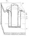
- FIG. 2is a detailed, cut-away generally cross-sectional view illustrating an embodiment of the externally accessible receptacle, shown with a can of soda positioned therewithin;
- FIG. 3is a perspective view of the embodiment as generally shown in FIG. 1, with the portable insulated case being shown in an open configuration;
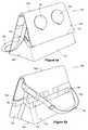
- FIG. 4 ais an isometric view, taken from above, behind and to the left side of an example of an embodiment of an insulated, collapsible soft sided, container in its fully expanded condition according to an aspect of the present invention
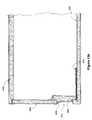
- FIG. 4 bis an isometric view of the insulated, collapsible soft sided, container of FIG. 4 a, taken from above, in front, and to the right hand side thereof, in its fully expanded condition;
- FIG. 4 cshows a container similar to the container of FIG. 4 a having an outer covering member
- FIG. 5 ais an isometric view of the container of FIGS. 4 a and 4 b taken from the same vantage point as FIG. 4 b, showing the container in a partially collapsed condition;
- FIG. 5 bis an isometric view of the container of FIGS. 4 a and 4 b taken from the same view point as FIG. 4 a, showing the container in a partially collapsed condition;
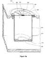
- FIG. 6 ais an isometric view of the container of FIGS. 4 a and 4 b taken from the same view point as FIG. 4 b, showing the container in a fully collapsed condition;
- FIG. 6 bis an isometric view of the container of FIGS. 4 a and 4 b taken from the same view point as FIG. 4 a, showing the container in a fully collapsed condition;
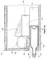
- FIG. 7 ais a cross-sectional view of the container of FIG. 4 a taken on section “ 7 a — 7 a ”, showing a receptacle in an open, and extended, position;
- FIG. 7 bis a cross-sectional view of the container of FIG. 4 a taken on section “ 7 b — 7 b ”, showing a receptacle in a closed position;
- FIG. 8 ashows a cross-section of an example of an alternative embodiment of a container similar to the container of FIG. 4 a, having receptacles of different sizes;
- FIG. 8 bshows a cross-section of an example of an alternative embodiment of a receptacle having an inwardly biased side-wall
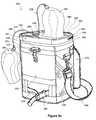
- FIG. 9 ashows a perspective view taken from above, in front, and to the left hand side of an example of an insulated soft-sided container according to the principles of the present invention, having a form similar to a golf bag and receptacle covers,
- FIG. 9 b nshows a perspective view of the container of FIG. 9 a from above, behind, and to the rear, with receptacle covers removed;
- FIG. 9 cshows the container of FIG. 9 a from above
- FIG. 9 dis a scab section of the container of FIG. 9 a, showing the construction thereof;
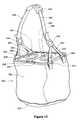
- FIG. 10shows an example of an alternative embodiment of an insulated, soft-sided container to that of FIG. 1 in the form of a bag to be carried by a strap;
- FIG. 11 ais a scab section of an alternative example of a container similar to the container of FIG. 4 a, having a receptacle having a thermal source element;
- FIG. 11 bis a scab section of an alternative to the container to that of FIG. 11 a;
- FIG. 12 ashows a cross-sectional view of an alternative example of an embodiment of an insulated container according to the present invention having a receptacle mounted to a side-wall thereof, in a closed position;
- FIG. 12 bshows a cross-sectional view of the container of FIG. 12 a, the receptacle being in an open condition;
- FIG. 12 cshows a partially cross-sectional view of the container of FIG. 12 b taken on section “ 12 c — 12 c ”.
- FIG. 13 ashows a partial cross-sectional view of an alternative example of an embodiment of an insulated container according to the present invention having a receptacle mounted in a sidewall and adjacent to a bottom wall thereof, in an occupied condition;
- FIG. 13 bshows a partial cross-sectional view of the container of FIG. 13 a with the receptacle thereof in a closed position;
- FIG. 14shows an example of an alternative embodiment of receptacle for use in the containers of FIGS. 1, 4 a, 8 , 9 a, 10 , 11 , 12 a, or 13 a.
- FIG. 15shows an example of an alternative embodiment to the receptacle of FIG. 14 having an integral bottle and receptacle assembly
- FIG. 16 ashows an example of an alternative embodiment of a receptacle having a moveable closure
- FIG. 16 bshows the closure of FIG. 16 a in a displaced condition
- FIG. 16 cshows the closure of FIG. 16 a installed in a rigid panel.
- Portable insulated case 20defines an insulated enclosure volume, generally designated at 22 . This volume is adequate to accommodate an assortment of food, or drink items or both, which can be held within the case 20 when closed.
- Case 20includes a top panel 24 , a bottom panel (not shown) and a sidewall panel 26 .
- Sidewall panel 26such as that illustrated, has four side portions 28 , 30 , 32 and 34 in a generally rectangular upstanding arrangement. Other configurations, arrangements or designs can be practised in order to provide a desired container shaping and sizing. Whatever arrangement of panels is chosen, insulated case 20 should be water-tight.
- top panel 24includes an opening 36 therethrough.
- the illustrated embodimentalso shows a second opening 38 . It will be appreciated that three or more openings could also be provided, depending upon the size of the top panel and the intended requirements or selected specifications of the portable insulated case.
- Each panel of the portable insulated case 20has insulative properties in that heat transfer is retarded across the panel.
- An example of a suitable panel construction in this regardincludes an internal core of foam 40 .
- Suitable foam polymersinclude ethylpropylene ethylene (EPE).
- EPEethylpropylene ethylene
- a typical corewill be about 8 mm thick.
- EPEethylpropylene ethylene
- Layers 42 and 44are preferably made of a material suitable for cleaning.
- a suitable material in this regardis nylon (T.M.) sheeting. Other suitable materials and combinations of materials may also be found.
- At least sidewall panel 26be pliable.
- top panel 24 bottom panelalso will be pliable.
- the soft-walled nature of the panelsrenders them more comfortable to handle, more easily. fit into tight spaces when required, and generally lighter in weight.
- a closure member or assemblysuch as the illustrated zipper 46 , is positioned with respect to the top panel 24 and sidewall panel 26 such that top panel 24 is openable.
- Other closure members or assembliesare possible, such as snaps, hook-and-loop arrangements, string ties, and the like.
- the exact location of the selected closure membercan vary, provided it allows for selective opening and closing of all, or a large portion of, top panel 24 , either alone or together with an upper portion of sidewall panel 26 . It is preferred that at least a portion of top panel 24 be able to remain attached to the rest of portable insulated case 20 . For example, in the embodiment illustrated in FIG. 3, the top panel remains attached to the sidewall along a hinge or edge area 48 .
- the portable insulated case 20When the portable insulated case 20 is in the open configuration illustrated in FIG. 3, the user has access to insulated enclosure volume 22 , thereby allowing items such as filled drink cans 50 and filled drink bottles 52 , whether glass or plastic, to be placed within and removed from insulated enclosure volume 22 . Access is thus permitted to one or more selected cans 50 , bottles 52 or the like, without having to undo the closure member, open the top, and thereby permit undesirable heat transfer through the resulting open area, whether the transfer be into the insulated case (when it is a cooler) or out of the insulated case (when it functions to keep warm items warm).
- itemssuch as filled drink cans 50 and filled drink bottles 52 , whether glass or plastic
- each receptacle 54 , 56is in general alignment with a respective one of openings 36 , 38 in top panel 24 .
- each externally accessible receptaclemay take a general form desired for the particular end use. These include sleeves, pockets, shaped cylinders and the like.
- Each such receptacle 54 , 56includes a mouth 58 .
- each mouth 58conforms to the shape of the opening 36 , 38 and has a perimeter size slightly less than that of the opening 36 , 38 .
- Mouth 38is selected to have a perimeter and size which closely approximates the external perimeter shape and size of the can, bottle or the like to be held such as can 50 or bottle 52 , illustrated.
- Each receptacle 54 , 56provides a downwardly depending structure which accommodates at least a substantial portion of the volume of the can, bottle or the like.
- the height of the receptacleis less than the total height of the can, bottle or the like in order to permit, and to facilitate digital access to can 50 , bottle 52 or such other object as may be seated therein; that is, a user can grasp and remove the can 50 , bottle 52 or the like from out of receptacle 54 , 56 when desired, such as in order to drink from, or pour from, can 50 , bottle 52 or the like.
- FIG. 2The structure of receptacle 54 or 56 is illustrated in FIG. 2 . It includes a downwardly depending sidewall 60 which is generally vertically oriented when portable insulated case 20 is in the upright position as illustrated in the Figures.
- the illustrated receptacle 54 , 56further includes a bottom wall 62 upon which can 50 , bottle 52 or the like can rest.
- downwardly depending sidewall 60has the configuration of a right cylinder, and the bottom wall 62 takes on the shape of a disc. This shaping is suited for closely accommodating illustrated can 50 or bottle 52 .
- the inner diameter of the downwardly depending sidewall 60approximates that of a typical can 50 or bottle 52 . It is especially preferred that at least the downwardly depending sidewall 60 be made of a pliable and somewhat resilient material. In that instance, the inside diameter of the sidewall 60 can be slightly greater than the outside diameter of the container whether can 50 or bottle 52 so that the container will slightly compress that is to say, will have an interference fit with, sidewall 60 so as to enhance the gripping security imparted by receptacle 54 or 56 onto the container, be it can 50 or bottle 52 .
- a material found to be suitable in this regardis poly (2-chloro-1,3-butadiene), also known as polychloroprene or neoprene (T.M.).
- the bottom wall 62can be made of the same material as the downwardly depending sidewall 60 .
- the material of the receptacleis a waterproof material. That is, if liquid should spill from can 50 or bottle 52 , for example, it will tend to be held within receptacle 54 or 56 and thereby be discouraged from dripping or leaking into insulated enclosure volume 22 .
- receptacles of rubber, or synthetic rubber foamsincluding open celled foams, and some closed cell foams, generally having a nylon or vinyl skin on the receptacle inside and outside walls, have been found to deflect or collapse when forced against more robust objects inside the case.
- a collapsible, or crushable receptacleis preferred, it is possible to make receptacles similar to receptacles 54 and 56 of a substantially rigid material intended to resist crushing.
- an ABS, hard nylon, or other stiff polymer, or aluminum or stainless steel receptaclecould be employed where more rigid properties are desired.
- receptacles 54 and 56have been illustrated as having a generally round, right cylindrical shape, one or the other, or both, could have a different cross-sectional profile, whether square, rectangular, elliptical, oval, hexagonal, octagonal, D-shaped, or some other shape.
- Receptacles 54 and 56could have different cross-sectional shapes, and could be of different sizes. For example, one may have a diameter for receiving a 355 ml soft drink can, the other may have a diameter for receiving a 385 ml can.
- one or the other, or bothmay be sized to receive a 750 ml or other capacity bottle such as a wine or soft drink bottle, or a 1 quart, 2 quart, or other capacity milk or juice carton.
- a 750 ml or other capacity bottlesuch as a wine or soft drink bottle, or a 1 quart, 2 quart, or other capacity milk or juice carton.
- the well of each receptaclemay be tapered, typically being narrower at the innermost end of the well than at the mouth.
- a taper in the nature of a draft anglemay facilitate removal from the mould.
- a modest taper, or a chamfer at the receptacle mouthmay facilitate entry of a bottle, can, or other object into the receptacle.
- Receptacles 54 and 56are to be mounted integrally with top panel 24 at openings 36 , 38 .
- Single-piece constructionis possible in this regard, although often an assembly can be somewhat more convenient, particularly when the receptacle material is different from that of top panel 24 .
- a flange member 66can be used to join the receptacle to the top panel.
- Illustrated flange member 66includes a horizontal plate 68 which overlies the opening 36 , 38 and the adjacent edge of the top panel 24 .
- a plurality of fastening devices, in the nature of flexing fasteners 70project from horizontal plate 68 into and through the top panel 24 .
- Horizontal backing plate 72are included to enhance the security of the connection between fasteners 70 and top panel 24 . In this regard, the fasteners 70 pass through respective openings provided in separate horizontal backing plate 72 . Fasteners 70 snap into place thereat.
- Flange member 66also includes a vertical annular leg 74 which downwardly depends from the horizontal plate 68 .
- a cut-out or indent in the nature of a shouldered annular rabbet 76is provided in receptacle sidewall 60 to accommodate the thickness and height of vertical annular leg 74 .
- any inherent flexibility of the receptacle materialcan permit compression of that material which is under the vertical annular leg 74 .
- the exposed surface of the vertical plateis flush with the inside surface of receptacle sidewall 60 , or, alternatively vertical annular leg 74 is slightly indented with respect to receptacle sidewall 60 . The surface of receptacle 54 or 56 will thus engage the container, whether can 50 or bottle 52 , when seated within receptacle 54 or 56 .
- insulated enclosure volume 22 of case 20will also contain a thermal energy storage medium to act as a heat source or sink.
- a thermal energy storage mediumcan be an object in the nature of a cooling source at a temperature below room temperature and, moreover, typically below the freezing point of water. Ice or commercially available freezing packs are suitable.
- FIG. 3illustrates the use of a heavy duty pouch 80 having easy openable and closeable means, in the nature of mating profile strips 82 . Refrigerator ice or the like can be inserted into pouch 80 to contain, for example, ice as it melts into water.
- Receptacles 54 and 56depend downwardly from top panel 24 into the insulated enclosure volume 22 and thus (when the insulated case is a cooler) within the cool environment of insulated enclosure volume 22 .
- Items in volume 22include the cooling member, typically included within, for example, heavy duty pouch 80 containing ice cubes or the like. Also often contributing to this cool environment within insulated enclosure volume 22 are other drink or food items enclosed therewithin. Because the receptacles extend into this environment, they can be positively affected by the environment of the insulated enclosure.
- a certain degree of heat transfercan occur across the walls of the receptacle.
- a can of sodafor example, which is well below room temperature when within insulated enclosure volume 22 may still tend to be subjected to the cooling environment of the insulated enclosure even after it is removed from volume 22 and placed within one of receptacles 54 or 56 , as seen in FIG. 1 and FIG. 2 .
- the walls of the receptacleallow a greater degree of heat transfer through them than is allowed by the panels of the portable insulated case 20 . It will be appreciated that, under this circumstance, the rate of thermal transfer through the receptacle walls will be faster than through the case panels.
- a can, bottle, or the likeWhen a can, bottle, or the like, is positioned within a receptacle, there occurs a reduction of heat transfer out of the can, bottle, or the like, and into the surrounding ambient environments. Maintaining a cool item cool also is achieved in part because a substantial portion of the can, bottle or the like is shaded from the sun or other heat generating sources by virtue of its being enclosed within receptacle 54 or 56 .
- receptacle 54 or 56itself has an insulative effect on that portion of can 50 , bottle 52 or the like which is enclosed within the receptacle. Such insulating effects occur irrespective of any cooling effect imparted through the receptacle wall by virtue of the cool environment of the insulated enclosure volume 22 .
- Receptacles 54 and 56tend to prevent spillage of an open drink, for example, while also tending to assist in keeping the drink cool for a longer period of time than is achieved by approaches which do not combine a holding function with a cooling function.
- the illustrated portable insulated case 20includes a zippered security pocket 86 which is provided for convenient storage of smaller items such as keys, money, wallets, watches, personal items and the like. It will be appreciated that the illustrated zipper can be substituted for by using other closure arrangements. Also illustrated is an outside mesh pocket 88 , which can be suitable for storing other items such as glasses, books, lotions and the like.
- the bottom panel (not shown) of the portable insulated case 22is preferably made of a non-skid, durable and water-resistant material, or has an outer layer composed of material having these properties.
- An adjustable carrying strap 90can be included as shown.
- a sheet of material, in the form of a top cover panel,can be positioned for temporary full closure or partial closure of one (or of each) receptacle mouth.
- a top cover panelcan be temporarily secured to the outside of the insulated case by any suitable connection means, such as zipper, hook-and-loop components, snaps, tabs, tie strings and the like (not shown).
- FIG. 1 and FIG. 3A total of two receptacles are shown in FIG. 1 and FIG. 3 .
- Other possible variationsprovide a single receptacle, which would be particularly suitable for use by a single person. Larger portable insulated cases can include a greater number of receptacles to accommodate a greater number of users. Correspondingly, the portable insulated case itself typically is larger in volume when there are more receptacles. In the illustrated arrangement of FIGS. 1, 2 and 3 a single-receptacle portable insulated case will accommodate from four to six 12-ounce cans, a dual receptacle portable insulated case will accommodate about twelve such cans, and a triple-receptacle portable insulated case will accommodate twenty-four such cans.
- a collapsible insulated portable soft sided container 100is shown in fully expanded, partially collapsed and fully collapsed positions in FIGS. 4 a and 4 b, FIGS. 5 a and 5 b, and FIGS. 6 a and 6 b respectively. It has an insulated shell 102 having a top wall, in the nature of a top panel 104 , a bottom panel 106 (shown in FIG. 7 a ), and sidewall panelling 108 extending between top and bottom panels 104 and 106 .
- Panelling 108has four facing portions, being front, rear, lefthand and right-hand facing portions 110 , 112 , 114 , and 116 respectively that define a generally rectangular container section of dimensions corresponding to the four side edges of each of top and bottom panels 104 and 106 . It may be noted that although panels 104 and 106 are of the same dimensions, such that portions 110 , 112 , 114 and 116 are each rectangular and share a common height, this need not necessarily be so. A pyramidal, inverted pyramidal, two sided cradle, or other form could be assembled.
- a closure memberin the nature of a zipper 120 , extends about three edges 121 , 122 , and 123 of top panel 104 , for mating with corresponding edges 124 , 125 and 126 of front, left hand, and right hand facing portions 110 , 114 and 116 .
- Rear edge 127 of top panel 104meets the top edge 128 of rear facing portion 112 at a juncture in the nature of a folding hinge 130 .
- Zipper 120is movable between a fully closed position in which all edges of top panel 104 are joined to the remainder of container 120 , and a fully open position in which top panel 104 is free to move upwardly and rearwardly on hinge 130 , thus giving access to a storage space 132 defined within shell 102 . By this access means a person may introduce or remove beverages, food items, or other objects from space 132 .
- Container 100has a carrying strap 134 of adjustable length by which container 120 may be lifted, with attachments on left and right hand facing portions 114 and 116 .
- a reinforcing band 136is mounted about the external periphery of sidewall 108 of container 120 , at a level intermediate the top and bottom panels.
- Band 136has, on a front facing portion thereof, an attachment member in the nature of a male or female hook-and-eye fabric attachment strip 138 .
- a corresponding female or male hook-and-eye fabric attachment stripis located on the inner face of top panel 104 near its distal edge, namely front edge 121 .
- Zipper 120can be moved to its fully open position to permit top panel 104 to be drawn forwardly and downwardly such that the hook-and-eye fabric strips engage, yielding the partially collapsed position shown in FIGS. 5 a and 5 b.
- Band 136also has a pair of left and right hand closure tabs 140 and 142 attached, by means of sewing, at the vertices formed at the junctures, respectively of front facing portion 110 and left hand and right hand facing portions 114 and 116 , at a level corresponding generally to that of band 136 .
- the inner faces of tabs 140 and 142have hook-any-eye fastener strips.
- Band 136has corresponding mating tab holder hook and eye fastener strips 144 and 146 , on the left and right hand facing portions 114 and 116 of sidewall 108 , to provide a land for tabs 140 and 142 when container 100 is in its fully open or partially open positions as shown in FIGS. 4 a and 4 b, and FIGS.
- Band 136also has, on rearwardly facing portion 112 , a pair of mating tab securing position hook and eye fastener strips 148 and 150 , such as are engaged by tabs 140 and 142 when container 100 is in its fully collapsed position, as shown in FIGS. 6 a and 6 b.
- Top panel 104 of container 100has a pair of receptacles indicated generally as 152 and 154 . Each is mounted in an opening 156 or 158 let through top panel 104 .
- Receptacles 152 and 154are identical in construction.
- Receptacle 152has a flanged fitting assembly 160 by which it is mounted to top panel 104 , a depending well assembly 162 mounted to assembly 160 (and top panel 104 ) for receiving, for example, can 50 or bottle 52 , and a cover assembly 162 , also mounted to assembly 160 , for covering receptacle 152 when it is not in use.
- Flanged fitting assembly 160includes an annular member 166 having a substantially planar, annular, radially outwardly extending flange in the nature of a leg member 168 , and a substantially downwardly extending, round cylindrical inner leg member 170 forming the inner lip of receptacle 152 .
- a capture, or backing member, in the form of a backing ring 172is used to clamp against the upper and lower skin 174 and 176 of top panel 104 , compressing insulation layer 178 in the process.
- Backing ring 172is secured in place by clinching fasteners 180 .
- a number of different types of fastenercould be used for this purpose, such as screws, rivets, snap fit plastic prongs, bonding inserts or other similar means.
- fasteners 180are formed integrally with leg members 168 and 170 , and have a split prong for insertion through mating apertures in backing ring 172 .
- Depending well assembly 162has a downwardly extending peripheral wall member 182 in the nature of a waterproof skirt or membrane having a closed base portion 184 .
- a circular seat 186is bonded within wall member 182 to rest upon base portion 184 .
- a can 50 , or bottle 52 placed within receptacle 152can stand upon seat 186 .
- the upper edge of wall member 182extends about the outside face of leg member 170 , and is also captured in place by backing ring 172 .
- Cover assembly 164includes a lid 190 , a stopper 192 centrally located relative to lid 190 and sized to fit within round cylindrical leg member 170 of flanged fitting assembly 160 , a hinge member 194 joining lid 190 to outwardly extending leg member 168 , and a detachable attachment fitting in the nature of a male (or female) snap 196 for mating with a female (or male) snap 198 centrally mounted on seat 186 of well assembly 162 .
- mating attachment fittingcould be used, such as hook-and eye fittings, magnetic fittings, a suction cup fitting, a ball-in-socket interference fitting, a half-turn or quarter turn twisting fastener fitting or other releasable attachment means by which seat 186 can temporarily be joined to cover assembly 164 as shown in FIG. 7 b.
- the position shown in FIG. 7 bis the closed, or storage position of receptacle 152 (or 154 ). In this position the space within insulated shell 102 that would otherwise be occupied by receptacle 152 (or 154 ) can more easily be used for the storage or carriage of other objects.
- receptacles 152 and 154tends to enhance their suitability for use in a collapsible container such as container 100 .
- receptacles 152 and 154have their cover assemblies in place, and, although not visible, their well assemblies collapsed to permit top panel 104 to be drawn down relatively tightly over the upper portion of front facing panel 110 to permit the hook-and eye fasteners to mate.
- the major portion of top panel 104remains substantially planar, as do front and rear facing portions 110 and 112 , whereas side facing panels 114 and 116 and bottom panel 106 , tend to be folded centrally.
- sidewall member 170is a substantially inelastic waterproof webbing material, such that when placed in the closed position it bunches and folds in the irregular manner indicated. Elasticized bands could be used to encourage more regular folding if desired.
- the flexibility of sidewall member 174is such that when not in use, it tends to present little resistance to collapse upon encountering objects within space 132 generally.
- a collapsible receptaclecan be formed, including the use of an easily deflected spongy material, a rubber or synthetic rubber cup or similar structure. It is advantageous that the material chosen for wall member 182 have a considerably higher thermal conductivity than an equivalent area of insulated shell 102 , so that an object in receptacle 152 (or 154 ) may be subject to heat loss (or gain) from space 132 more readily than with the external ambient environment. A similar consideration applies to seat 186 .
- stopper 192have a resistance to heat transfer comparable to the resistance of the adjacent portions of top panel 104 to discourage unwanted heat gain from, or heat loss to, space 132 when receptacle 152 (or 154 ) is not in use.
- cover assembly 164is linked to flanged fitting assembly 160 by hinge member 194 , it is possible to use other means to govern the relationship of cover assembly 164 to flanged fitting assembly 160 , particularly for the purpose of preventing, or discouraging inadvertent loss of cover assembly 164 if not joined to container 100 in some manner.
- An external storage pocketcould be provided, as could hook-and-eye, or other types of releasable fasteners.
- a retainer in the nature of a cable, strap, lanyard, or chainis also suitable for this purpose.
- receptacles 152 and 154have a cover. They could be open, as are receptacles 153 and 155 illustrated in FIG. 4 c.
- container 101in place of cover assembly 164 , container 101 , in other respects similar to container 100 , has a fly, overlay, or cover 165 .
- cover 165is mounted to container 101 in the region of hinge 131 , and has a three-sided depending skirt 167 for overlapping the edges of top panel 105 .
- the lower hem of skirt 167has an elastic strap sewn inside to cause the hem to draw snugly against container 101 in the manner of a fitted sheet.
- a drawstring or similar devicecould also be used.
- hook-and-eye fabric strips 171for engagement of mating hook-and-eye fabric strips 173 mounted to sidewalls left and right hand facing portions 115 and 117 .
- Receptacle 152could have a square, rectangular, hexagonal, D-shaped, or other cross-sectional profile.
- Well assembly 162is shown in FIG. 7 a as depending in a manner as to leave a clearance, in indicated as ‘G’, between base portion 184 and the upper face of bottom panel 106 , or, as illustrated, from liner 188 that lies thereupon.
- the inner wall of receptacle 152(that is, the wall surface closest to the can, bottle, or other objected seated in the receptacle) can have a vinyl sheet skin or liner.
- FIG. 8 aan alternative embodiment of receptacle, indicated generally as 200 , has a waterproof peripheral wall member 202 of sufficient longitudinal extent that base portion 184 rests upon, or is ultimately supported by, bottom panel 106 .
- a hook-and-eye fabric fastenerin the nature of a Velcro (T.M.) fastener has one strip mounted to the underside of the base of receptacle 200 and another, engageable part mounted to bottom panel 106 such that, in use, when the hook-and-eye fastener is engaged, base portion 184 is discouraged from shifting relative to bottom panel 106 . This may tend to be desirable particularly when the container is being moved.
- an auxiliary hook-and-eye strip 201 for engaging the hook-and eye-strip portion adjacent to base portion 184is shown in FIG. 8 a mounted to an upper region of the inside surface of top wall panel 205 , and provides a storage position for base portion 184 when receptacle 200 is not in use.
- Auxiliary strip 201could also be located on the inside surface of sidewall 207 , depending on the type of closure member used to provide access to the interior of the container.
- an alternative well assembly 204has a biasing member in the nature of an elasticized medial band 206 such that wall member 208 will be biased inwardly to engage the exterior of an object, such as bottle 210 , located in assembly 204 .
- a biasing memberin the nature of an elasticized medial band 206 such that wall member 208 will be biased inwardly to engage the exterior of an object, such as bottle 210 , located in assembly 204 .
- More than one biasing membercould be used, and other types of biasing members could be employed.
- wall member 208could be of a thickened, elastomeric foam construction presenting a profile, whether vertically ribbed or otherwise, extending inwardly of the circumference of the opening at lip 212 of assembly 204 to encourage an interference fit.
- wall member 208could be replaced by a pre-stretched elastomeric wall, such as a rubber wall, stretched by a base plate, like item 184 , and by a ring fitting, like flanged fitting assembly 160 .
- the cross-sectional profile of the undeflected wall member 214is generally as shown in FIG. 8 b. Introduction of a bottle therein would tend to cause outward deflection of wall member 214 , stretching it hoop-wise.
- an optional, deformable fender lip 216is shown in both receptacle 200 and 204 .
- an insulated pack having a shape that is generally similar to a golf bag, but on a smaller scale,is shown generally as 220 . It has a leading portion 222 , a trailing portion 224 , a pair of left and right hand side portions 226 and 228 , a top portion 230 having a lid 232 , and a bottom portion 234 .
- the major part of pack 220is an insulated compartment 236 bounded by a modestly flexible soft shell insulating wall, 238 , whose construction is shown in FIG. 9 d.
- the breadth of pack 220that is, the overall width when viewed from the leading or trailing directions, is about 81 ⁇ 2′′ empty. When undeformed, pack 220 has a gently bulging D-shaped cross section when seen from above, similar to a golf bag, although this may change somewhat when loaded. The breadth is roughly the same as the thickness of a middling to large size of golf bag.
- wall 238has an outer covering 242 of webbed construction, and an internal closed cell foam layer 244 within a covering 242 .
- the interior of pack 220has a flexible, waterproof liner 246 , such as may be made of a flexible vinyl sheet or other suitable material.
- Liner 246is not, in the example illustrated, fixed to the bottom of compartment 236 , but can be pulled out of compartment 236 to an inverted position (while still remaining attached at rim 248 ) to facilitate washing with soap, and to facilitate drying, to discourage the growth of fungus and so on.
- Liner 246has a single circumferential seam to join a bottom face, and a single wall seam running from the circumferential bottom seam to rim 248 .
- liner 246could be made from a polymer that has been impregnated with an antimicrobial compound prior to fabrication, a desirable feature for this kind of liner.
- the top of compartment 236is formed by generally D-shaped lid 232 .
- Lid 232also has a through section structure of a flexible reflective inner layer, 252 , a flexible skin in the nature of a canvas or webbing covering, 254 , and a flexible closed cell insulation layer 255 , (similar to layer 244 , above) captured in between.
- Lid 232is joined to the main body of pack 220 , along the roughly straight side of the ‘D’ shape, at a juncture indicated as 257 .
- Lid 232is divided into fore and aft portions 231 and 233 by a transversely extending medial hinge in the nature of a flexible fabric hinge 256 .
- Rearward portion 233 of lid 231is bounded along its relatively straight side by flexible hinge 256 , and along its arcuate side by a peripheral tracked closure in the nature of a zipper 258 by which it is joined to the upper edge of trailing portion 224 .
- a peripheral tracked closurein the nature of a zipper 258 by which it is joined to the upper edge of trailing portion 224 .
- Rim 248has a spongy beaded lip 260 wrapped within the upper edge of liner 246 , adjacent to the set of zipper teeth 259 of zipper 258 that is mounted to the main body of pack 220 .
- Lid 232has a mating generally arcuate lip 262 adjacent to the set of zipper teeth 261 of zipper 258 mounted to lid 232 . When zipper 258 is closed, lip 262 is drawn down to bear on the outside surface of beaded lip 260 , encouraging a sealing contact to be formed.
- thermal transfer storage medium compartmentis provided by the use of a sack 264 for holding the thermal storage medium 266 .
- Thermal storage medium 266may be used as a source of heat to be transferred into the contents of compartment 236 , that is, to maintain a warm temperature distribution in compartment 236 .
- the thermal storage medium 266can be used as a heat sink to maintain a cool, chilled, or freezing temperature distribution in the contents of compartment 236 , as circumstances may require.
- Sack 264has an array of perforations 268 to allow air to circulate through sack 264 more easily, facilitating drying of sack 264 after washing.
- Insulated pack 220also has an auxiliary compartment in the nature of a valuables compartment 270 , mounted to trailing portion 224 , externally of soft shelled insulating wall 238 .
- Cover 242is made of a 600 denier polyester fabric, treated, as are all external surfaces of pack 220 , to be stain and water resistant.
- Other wall fabricscan be used, such as leather or leather-like vinyl.
- a vented, see-through pocket 271is mounted externally to trailing portion 224 , and is of a size for accommodating, for example, extra golf balls, gum, candy bars or other items.
- the open form mesh 273permits objects in pocket 271 to dry more easily.
- Pocket 271is closed by a sliding closure in the form of zipper 275 .
- a main attachmentsuitable, for example, for hanging pack 220 from a golf bag, or for clipping pack 220 to a golf bag or golf cart, is shown as a quick release brass hook fitting 272 is mounted to an upper region of pack 220 on leading portion 222 .
- Hook fitting 272is free to revolve within its hinge fitting, 274 , which itself is able to swing up and down within the confines of a broad loop of webbing 276 .
- a second attachment, suitable for tightening to another fastening location of a golf bag or golf cart, in the nature of an adjustable cinch strap 278is mounted to a lower region of pack 220 , also on leading portion 222 .
- Strap 278has a releasable catch 280 , and can be used to tighten the lower region of pack 220 to a golf bag, golf cart, or other object, to restrain its swaying motion about the main attachment at hook fitting 272 . It is anticipated that a significant use of main insulated compartment 236 will be for carrying cans of liquid, such as carbonated beverages, fruit drinks, or beer, whether or not accompanied by ice cubes or crushed ice.
- the embodiment illustratedhas a capacity of 12 cans of 385 ml plus ice, in FIGS. 9 a, 9 b and 9 c.
- the main attachment at hook fitting 272is able to carry the entire weight of pack 220
- the second attachment, at cinch strap 278inhibits swaying of pack 220 about the first attachment.
- Fitting 272 and strap 278co-operate to provide a means for orienting pack 220 , and thus for orienting receptacles 288 and 290 , described below.
- lid 232is provided with a carrying handle 282 having a padded bail 284 .
- pack 220can be carried by a shoulder strap 286 fastened by spring clips to D-shaped rings, mounted on either of sides 226 and 228 .
- a pair of receptacles 288 and 290are set in leading portion 231 of lid 232 , that is to say, receptacles 288 and 290 lie forward of hinge 256 . As such, access to compartment 236 by opening trailing portion 233 does not require that leading portion 231 be folded forward. Thus, items can be placed in, or removed from compartment 236 while another object, or objects, occupies one or both of receptacles 288 and 290 .
- Removable insulated covers 292 and 294having a general appearance similar to the appearance of coverings for driving golf clubs, such as woods, are provided for covering that portion of a beverage container, such as a beer can that would stand proud of lid 232 when seated in either of receptacles 288 or 290 .
- Coverings 292 and 294are restrained from being separated from pack 220 by retainers in the nature of lanyards 296 , rather in the manner of golf club covers generally.
- Covers 292 and 294may be held in place merely by their fit on a beer or other can, such as can 50 , or, alternatively, fastening strips, such as hook-any-eye fabric fastening strips, or other suitable means, such as snaps, zippers or similar devices, may be provided for more positive engagement with lid 232 in particular, and pack 220 in general. Covers 292 and 294 encourage the maintenance of the contents of can 50 at a cooler (or, as may be desired, warmer) temperature than might otherwise be the case if can 50 were exposed to the sun or to the wind directly. Covers 292 and 294 also serve to discourage or contain spillage from open beverage containers lodged in either of receptacles 288 or 290 .
- Lid 232could, as with top panel 104 , be formed in a single panel to accommodate receptacles 288 and 290 .
- Insulated covers 292 and 294need not be in the form of golf club covers, but could be in any suitable form for providing temporary external cover for items in receptacles 288 and 290 .
- an insulated containeris shown in the form of a bag 320 having a flexible walled sack 322 , a receptacle holding panel in the nature of a relatively stiff top panel 324 , and a carrying strap assembly 326 .
- Panel 324is an insulated sandwich having an external webbing layer overlying an external vinyl skin, an internal vinyl skin, and a foam core between the two vinyl skins.
- Panel. 324could also be replaced by a hard-shell panel, whether made of a substantially rigid polymer, or a metal.
- sack 322is a relatively thin walled, watertight fabric or webbing membrane sewn (or, alternatively bonded) together in the general form of a pouch. That is, sack 322 is relatively amorphous, and lacks the stiffness to stand upright under its own weight. It is, in that sense, a “bag” as opposed to a casing.
- the lower extremities of sack 322may have an extra thickness, typically of a wear resistant facing material 327 suitable for resting on the ground.
- Sack 322has a leak resistant, vinyl liner (not shown) similar to the vinyl liner 246 of pack 220 described above.
- Top panel 324is of similar construction to top panel 24 of case 20 , and is sufficiently stiff to accept the installation of a pair of hinged doors 328 and 330 , sharing a common medial flexible hinge 332 .
- a receptacle 334 or 336In the midst of each of doors 328 and 330 is a receptacle 334 or 336 , respectively, of the same general construction as receptacle 54 or 56 .
- Each of doors 328 and 330has a closure member, in the nature of a zipper 338 or 340 extending around the remaining three sides of the respective doors, by which access to the interior enclosed space of bag 320 is obtained.
- Strap assembly 326has a shoulder band 342 with a shoulder pad 344 . Each end of band 342 is secured to a buckle or clasp 346 or 348 . A pair of spreader straps 350 , 352 are fed through clasps 346 and 348 and secured at support rings 353 , 354 , 355 , and 356 mounted about the top edge of sack 322 to discourage, or reduce, tipping of top panel 324 when bag 320 is hanging from strap assembly 326 .
- a beveragecan repose in one of receptacles, receptacle 334 for example, while access is obtained to the interior of sack 322 by opening the other door, such as door 330 .
- bag 320can be used to encourage objects to remain either heated or cooled relative to their surrounding ambient environment, and may contain heating or cooling sources, such as heating pads or cooling packs for that purpose.
- the capacity of bag 320is such that it can accommodate more objects in addition to the inwardly extending portions of receptacles 334 and 336 .
- receptacles 334 and 336can be made of a variety of materials to permit them to collapse or deflect when not in use, and can have rectangular, round, hexagonal, octagonal or other shaped cross-sections.
- Receptacles 334 and 336could also have covers if desired, whether similar to cover assembly 164 of container 100 , or of upstanding covers for shading, or sheltering, an object seated in the receptacle, such as covers 292 or 294 of container 220 , whether in the shape of golf club covers or some other shape.
- bag assemblies having only a single receptacle, or more than two receptaclesare possible, as are bag assemblies having a receptacle in a non-opening portion of a top panel, with opening portions of a top panel that do not have receptacles mounted therein.
- bag assemblies having a receptacle in a non-opening portion of a top panel, with opening portions of a top panel that do not have receptacles mounted thereinare possible.
- FIG. 11 aA partial section is shown in FIG. 11 a of an insulated container 360 having a top panel 362 , a sidewall panel 364 , and a bottom panel 366 all of generally similar water-tight construction to that of case 20 , container 100 , and container 200 .
- Container 360could have a water tight liner similar to liner 246 , although this is not shown in FIG. 11 a.
- a receptacle 370is shown having a flanged fitting 372 and a co-operating annular backing plate 373 for clamping the adjacent land of top panel 362 when fasteners 374 are tightened. (Other types of fastening arrangement could be used).
- a downwardly extending sidewallis indicated as 378 .
- Base member 380is made of a material of suitably high thermal conductivity to promote, or act as a medium for, heat transfer between puck 382 and, for example can 50 or bottle 52 when seated in receptacle 370 .
- puck 382rests on bottom panel 366 .
- a sidewall having less depth than sidewall 378could be employed, such that puck 382 would be suspended at some intermediate height above bottom panel 366 .
- puck 382can be suspended adjacent to top panel 362 .
- puck 378is a heat sink to provide cooling within container 360 , either a heat source or a heat sink can be employed, depending on the need for heating or cooling.
- FIG. 11 aa covering could be provided, for example, similar to that shown in either FIGS. 7 a and 7 b, or in FIG. 9 a.
- a coveringis shown in the nature of a skirt, or boot, or shroud 396 .
- the periphery of the lowermost extremity, indicated as hem or cuff 397is captured under flanged fitting 372 .
- collar 398The periphery of the uppermost edge, being a neck or waist, and indicated as collar 398 is folded over to accommodate a drawstring 399 , by which collar 398 can be drawn tight to gather, as shown, typically about the circumference of a can, or about the neck of a bottle, or, if tall enough, above the top of the can or bottle.
- FIGS. 12 a and 12 bshow a partial section of a soft sided container 400 , generally similar to container 200 described above.
- Container 400differs from container 200 insofar as it has a suspended receptacle 402 mounted in an insulated sidewall panel 404 .
- a bottom panelis shown as 406
- a top panelis shown as 408 .
- Top panel 408is connected to sidewall panel 404 by a tracked closure member in the nature of a zipper 410 . Thus top panel 408 is openable to give access to the internal enclosure space 412 of container 400 .
- An opening 414is defined in sidewall panel 404 , and a collapsible sidewall member in the nature of a water-tight nylon (T.M.) web 416 is mounted about lip 418 of opening 414 .
- a closure member in the nature of a hinged flap, or door 420is mounted on a fabric hinge to the inside of sidewall panel 404 , and is moveable from a closed position as shown in FIG. 12 a for discouraging heat transfer through opening 414 , to an open position as shown in FIG. 12 b for permitting an object, such as bottle 52 , to be introduced through opening 414 to seat in receptacle 402 .
- a portion of bottle 52protrudes through opening 414 to facilitate removal from receptacle 402 from time to time as may be desired.
- web 416can hang, collapsed, unobtrusively within the enclosed space of container 400 , typically adjacent a lower portion of sidewall panel 404 .
- the return of door 420 to its closed position, as shown in FIG. 12 a,is encouraged by a biasing member in the nature of an elasticized band 422 shown in FIG. 12 c.
- Band 422is mounted to the external face of sidewall 404 , extends about the exterior of web 416 , and along the inwardmost face of door 420 .
- Other types of biasing memberssuch as a spring could be used, or door 420 could move to its closed position under gravity alone.
- the enclosed space of container 400can also accommodate other objects than those that may seat within receptacle 402 , as illustrated by a number of bananas in a mesh pouch 424 , or can 50 set about with ice-cubes 426 , shown floating in meltwater 428 .
- bottle 52hangs in such a manner as to cause its neck to engage the uppermost portion of the periphery of the lip of receptacle 402 , limiting the angle at which bottle 52 can hang.
- a container similar to container 400is indicated generally as 450 in FIGS. 13 a and 13 b.
- opening 452 and water tight receptacle 454are similar to opening 414 and receptacle 402 , but are located in sidewall panel 456 adjacent to bottom panel 458 to permit bottle 52 to be placed in a position lying on bottom panel 458 .
- Other objects, such as can 50can also be placed in the enclosed space of container 450 , and a cooling or heating medium, such as ice pack 460 , can be placed about, or as shown, on top of bottle 52 and can 50 .
- Other itemssuch as fruit and cheese 462 and 464 are also shown.
- door 466 of receptacle 454is shown urged to its closed position by a biasing member in the nature of an elasticised hinge 468 .
- Watertight sidewall 470 of receptacle 454lies upon bottom panel 458 when not in use.
- Sidewall panel 456has a shoulder 472 that acts as a retainer for discouraging bottle 52 from leaving receptacle 454 unexpectedly.
- Bottle 52can be drawn outwardly past shoulder 472 when required, but is intended to be a relatively tight fit.
- a stiff seat membercould be placed at the depending end of either receptacle 402 or 454 .
- Such a seat membercould resemble seat 186 of container 100 shown in FIG. 7 a. In the collapsed position of FIG. 13 b, such a seat would also tend to lie flat against bottom panel 458 .
- a removable receptacle assembly 500is shown in FIG. 14 . It is mounted in an insulated panel 502 , such as might be analogous to top panel 24 of case 20 , top panel 104 of container 100 , or other insulated panels in which a receptacle can be mounted. Panel 502 has an opening, generally indicated as 504 .
- a panel fitting 506mounts in opening 504 in a manner generally similar to the mounting of the flanged receptacle fitting described above, such that upper skin 508 , lower skin 510 , and insulating layer 512 are clamped between a radially outwardly extending flange 514 of fitting 506 , and a backing ring 516 by fasteners 518 , shown as flush countersunk plastic rivets.
- Fitting 506has a downwardly extending circular cylindrical wall 520 having a female thread 522 .
- Receptacle assembly 500also has a well 524 having a water-tight well sidewall 526 and a seat 528 for location in the bottom of well 524 .
- the upper edge of sidewall 526is captured between a ring fitting 530 and an annular face plate 532 , the three parts being fastened together by rivets 534 .
- Ring fitting 530has a radially outwardly extending shoulder 536 for abutting the upward face of flange 514 , and a downwardly extending generally cylindrical leg 538 having a male thread 540 for engaging female thread 522 of fitting 506 .
- Face plate 532has a pair of upwardly extending abutment members, in the nature of thumb-screw wings 542 and 544 , by which a person may cause threads 522 and 540 to tighten or loosen.
- the receptacle 546 of receptacle assembly 500may then be moved between an installed position in which receptacle 546 is engaged within fitting 506 , and a removed position in which receptacle 546 is not engaged within fitting 506 .
- Receptacle assembly 500is also shown to include a cover 548 for snap fitting engagement within the opening 550 defined in face plate 532 , cover 548 also having wings 552 to permit it to be removed. Cover 548 is secured to face plate 532 by a cable 554 .
- a bottle assemblyis indicated generally as 600 .
- a fitting 602 similar to fitting 506 of receptacle assembly 500is shown mounted in an insulated panel 604 , in the manner of that shown in FIG. 14 .
- assembly 600employs a bottle 606 having an threaded ring 608 .
- the closed end 610 of bottle 606can be introduced into opening 612 in panel 604 and ring 608 engages fitting 602 in the manner of fitting 506 and ring fitting 530 as described above.
- the neck of bottle 606protrudes from opening 612 to facilitate removal of bottle 606 when desired.
- releasable engagement meanscould be used rather than, a threaded fitting.
- a spring-loaded detentsuch as a ball or knob detent in place of the threads of fitting 602 for engaging a depression, or groove, in threaded ring 608 could be used.
- FIG. 16 ashows a receptacle 650 having a closure in the nature of a heat transfer barrier 652 for discouraging unwanted heat transfer to or from the enclosed space of container 654 is mounted inwardly of a fitting 656 .
- Barrier 652also discourages the entry of unwanted foreign objects.
- Barrier 652has eight inwardly extending, generally triangular, nested, overlapping flexible, resilient fingers 658 . As shown in FIG. 16 b, when the closed end of a can 659 is introduced into opening 660 , it causes tips 662 of fingers 658 to deflect downwardly and radially outwardly to accommodate the passage of bottle 52 . When bottle 52 is removed, fingers 658 return to their former, closed position.
- Base element 670has a central well 672 , for a narrow object, and a tapered, conical surround 674 .
- the taperis intended to assist objects in centering themselves in well portion 676 of receptacle 650 .
- Fingers 658will also assist in tending to center objects such as can 659 .
- FIG. 16 cshows receptacle 650 adapted to be mounted to a hard shell panel 680 of a hard shell container 682 having external insulation 684 .
- hard shell container 682has stiff top, side and bottom panels 680 , 686 , and 688 respectively, not all panels need be stiff.
- some solid, monolithic panelscould be replaced by a rigid framework.
- the receptacle assemblies described hereinabove in relation to FIGS. 1 a to 15could also be adapted to mounting in a hardshell panel.
- the hardshell panelsmay be fabricated from substantially rigid polymers, or from a metal such as, for example, aluminum or stainless steel.
Landscapes
- Engineering & Computer Science (AREA)
- Chemical & Material Sciences (AREA)
- Combustion & Propulsion (AREA)
- Physics & Mathematics (AREA)
- Mechanical Engineering (AREA)
- Thermal Sciences (AREA)
- General Engineering & Computer Science (AREA)
- Packages (AREA)
- Details Of Rigid Or Semi-Rigid Containers (AREA)
Abstract
Description
Claims (20)
Priority Applications (1)
| Application Number | Priority Date | Filing Date | Title |
|---|---|---|---|
| US10/023,325US6481239B2 (en) | 1998-03-09 | 2001-12-17 | Insulated container and receptacle therefor |
Applications Claiming Priority (4)
| Application Number | Priority Date | Filing Date | Title |
|---|---|---|---|
| US09/036,566US5924303A (en) | 1998-03-09 | 1998-03-09 | Insulated soft-sided portable case having externally accessible receptacle |
| US09/264,541US6116045A (en) | 1998-03-09 | 1999-03-08 | Insulated container and receptacle therefor |
| US09/629,284US6363739B1 (en) | 1998-03-09 | 2000-07-31 | Insulated container and receptacle therefor |
| US10/023,325US6481239B2 (en) | 1998-03-09 | 2001-12-17 | Insulated container and receptacle therefor |
Related Parent Applications (1)
| Application Number | Title | Priority Date | Filing Date |
|---|---|---|---|
| US09/629,284DivisionUS6363739B1 (en) | 1998-03-09 | 2000-07-31 | Insulated container and receptacle therefor |
Publications (2)
| Publication Number | Publication Date |
|---|---|
| US20020043076A1 US20020043076A1 (en) | 2002-04-18 |
| US6481239B2true US6481239B2 (en) | 2002-11-19 |
Family
ID=21889312
Family Applications (5)
| Application Number | Title | Priority Date | Filing Date |
|---|---|---|---|
| US09/036,566Expired - LifetimeUS5924303A (en) | 1998-03-09 | 1998-03-09 | Insulated soft-sided portable case having externally accessible receptacle |
| US09/264,541Expired - Fee RelatedUS6116045A (en) | 1998-03-09 | 1999-03-08 | Insulated container and receptacle therefor |
| US09/264,075Expired - LifetimeUS6067816A (en) | 1998-03-09 | 1999-03-08 | Insulated soft-sided portable case having externally accessible receptacle |
| US09/629,284Expired - Fee RelatedUS6363739B1 (en) | 1998-03-09 | 2000-07-31 | Insulated container and receptacle therefor |
| US10/023,325Expired - LifetimeUS6481239B2 (en) | 1998-03-09 | 2001-12-17 | Insulated container and receptacle therefor |
Family Applications Before (4)
| Application Number | Title | Priority Date | Filing Date |
|---|---|---|---|
| US09/036,566Expired - LifetimeUS5924303A (en) | 1998-03-09 | 1998-03-09 | Insulated soft-sided portable case having externally accessible receptacle |
| US09/264,541Expired - Fee RelatedUS6116045A (en) | 1998-03-09 | 1999-03-08 | Insulated container and receptacle therefor |
| US09/264,075Expired - LifetimeUS6067816A (en) | 1998-03-09 | 1999-03-08 | Insulated soft-sided portable case having externally accessible receptacle |
| US09/629,284Expired - Fee RelatedUS6363739B1 (en) | 1998-03-09 | 2000-07-31 | Insulated container and receptacle therefor |
Country Status (2)
| Country | Link |
|---|---|
| US (5) | US5924303A (en) |
| CA (1) | CA2264990C (en) |
Cited By (107)
| Publication number | Priority date | Publication date | Assignee | Title |
|---|---|---|---|---|
| US20030015538A1 (en)* | 2001-07-06 | 2003-01-23 | Milton Lassiter | Two-liter cooler |
| US20030136271A1 (en)* | 2002-01-23 | 2003-07-24 | Lg Electronics Inc. | Vegetable box for refrigerator |
| US20040035119A1 (en)* | 2002-08-26 | 2004-02-26 | Slone Carolyn L. | Thermal Conditioning beverage container holder |
| US20040144686A1 (en)* | 2001-05-14 | 2004-07-29 | Leamy John T. | Bulk foodstuff container method and assembly |
| US20050082303A1 (en)* | 2003-10-15 | 2005-04-21 | Robert Cantwell | Integrated beverage holder |
| US20050133399A1 (en)* | 2003-12-19 | 2005-06-23 | Fidrych Paul J. | Backpack with insulated beverage pocket |
| US20050211729A1 (en)* | 2004-08-17 | 2005-09-29 | Bassett Wade M | Liquid dispenser |
| US20050263528A1 (en)* | 2004-05-28 | 2005-12-01 | Igloo Products Corporation | Climate controlled dry goods storage |
| US20060102497A1 (en)* | 2003-11-27 | 2006-05-18 | Fashion Production | Insulated carrier |
| US20060180254A1 (en)* | 2004-11-16 | 2006-08-17 | Morley Gary R | Combination golf club headcover and beverage cooler |
| US20060196218A1 (en)* | 2005-03-01 | 2006-09-07 | California Innovations Inc. | Insulated container and cushion assembly |
| US20060239593A1 (en)* | 2005-04-21 | 2006-10-26 | Nike, Inc. | Bag with insulated beverage pocket |
| US20060251343A1 (en)* | 2005-05-09 | 2006-11-09 | True Charles W | Flexible independent multi-layer container and method for forming |
| USD532637S1 (en) | 2004-12-17 | 2006-11-28 | Mbhd, Llc | Liquid dispenser body |
| US20070189932A1 (en)* | 2006-02-10 | 2007-08-16 | Joe Glenn | Antimicrobial reusable plastic container |
| US20070187416A1 (en)* | 2006-02-16 | 2007-08-16 | Maxson Floyd S | Insulating container |
| US20070210228A1 (en)* | 2006-03-07 | 2007-09-13 | Shaw Company | Beverage container holder device |
| US20070278234A1 (en)* | 2006-05-31 | 2007-12-06 | Mogil Melvin S | Container with expandable portion |
| US7464567B1 (en) | 2005-05-17 | 2008-12-16 | Crossley Rita J | Apparatus for cooling and dispensing wine |
| USD607697S1 (en)* | 2009-04-23 | 2010-01-12 | Paul Whitlock | Cooler |
| USD608159S1 (en)* | 2009-04-23 | 2010-01-19 | Paul Whitlock | Cooler |
| USD619855S1 (en)* | 2009-10-15 | 2010-07-20 | The Coleman Company, Inc. | Soft-sided insulated container |
| US20100183789A1 (en)* | 2009-01-16 | 2010-07-22 | Propeller Inc. | Method and apparatus for making frozen comestibles |
| US8251110B2 (en) | 2004-08-17 | 2012-08-28 | Mbhd, Llc | Filling adapter |
| US20130043285A1 (en)* | 2011-08-20 | 2013-02-21 | James Christopher CORDRAY | Vending backpack |
| US8485327B1 (en)* | 2010-04-22 | 2013-07-16 | Tiffany Dalrymple | Luggage with integrated eating surface |
| US20130247606A1 (en)* | 2012-03-21 | 2013-09-26 | Glen R. Suchecki | Insulated container and insert |
| US8562065B2 (en)* | 2011-05-25 | 2013-10-22 | Ford Global Technologies, Llc | Vehicle trim panel having beverage retainer and method |
| US8763848B2 (en)* | 2011-05-20 | 2014-07-01 | Bf Gate Mate Inc. | Container for a tailgate party |
| US8777045B2 (en) | 2012-06-25 | 2014-07-15 | California Innovations Inc. | Insulated container with work surface |
| US20150027833A1 (en)* | 2009-11-30 | 2015-01-29 | Thule Organization Solutions, Inc. | Backpack with integrated rigid storage container |
| US8961163B2 (en) | 2013-01-16 | 2015-02-24 | Propeller, Inc. | Apparatus for making frozen comestibles |
| USD732349S1 (en) | 2014-02-07 | 2015-06-23 | Yeti Coolers, Llc | Insulating device |
| USD732348S1 (en) | 2014-02-07 | 2015-06-23 | Yeti Coolers, Llc | Insulating device |
| USD732350S1 (en) | 2014-02-07 | 2015-06-23 | Yeti Coolers, Llc | Insulating device |
| USD732899S1 (en) | 2014-02-07 | 2015-06-30 | Yeti Coolers, Llc | Insulating device |
| US20150217595A1 (en)* | 2014-02-06 | 2015-08-06 | Simtastec | Paint can handle |
| US9114839B2 (en)* | 2011-05-25 | 2015-08-25 | Ford Global Technologies, Llc | Vehicle trim component having beverage retainer and method |
| US9139352B2 (en) | 2014-02-07 | 2015-09-22 | Yeti Coolers, Llc | Insulating container |
| US9254022B2 (en) | 2012-02-22 | 2016-02-09 | Earthly Goods International, Llc | Self-supporting bag with insulated compartment |
| US9272444B2 (en) | 2013-07-18 | 2016-03-01 | Propeller, Inc. | Ice mold |
| US20160073752A1 (en)* | 2013-05-01 | 2016-03-17 | Stephen Daly | Improvements in wheeled suitcases |
| US9408445B2 (en) | 2013-03-01 | 2016-08-09 | California Innovations Inc. | Soft-sided insulated container with inflatable wall structure |
| USD773809S1 (en) | 2015-02-12 | 2016-12-13 | Chillinder Coolers, LLC | Bag |
| US20170036844A1 (en)* | 2014-02-07 | 2017-02-09 | Yeti Coolers, Llc | Insulating Device and Method for Forming Insulating Device |
| US9578939B2 (en)* | 2015-02-23 | 2017-02-28 | Thomas Nebeling | Rolling luggage apparatus having an integral cup holder |
| USD786559S1 (en) | 2014-09-23 | 2017-05-16 | Yeti Coolers, Llc | Insulating device |
| USD798670S1 (en) | 2016-02-05 | 2017-10-03 | Yeti Coolers, Llc | Insulating device |
| USD799276S1 (en) | 2016-02-05 | 2017-10-10 | Yeti Coolers, Llc | Insulating device |
| USD799277S1 (en) | 2016-02-05 | 2017-10-10 | Yeti Coolers, Llc | Insulating device |
| USD799905S1 (en) | 2016-02-05 | 2017-10-17 | Yeti Coolers, Llc | Insulating device |
| USD801123S1 (en) | 2016-02-05 | 2017-10-31 | Yeti Coolers, Llc | Insulating device |
| US9809376B2 (en) | 2012-06-25 | 2017-11-07 | California Innovations Inc. | Soft-sided insulated container with lid fitting |
| USD802373S1 (en) | 2016-02-05 | 2017-11-14 | Yeti Coolers, Llc | Insulating device |
| USD805851S1 (en) | 2016-06-01 | 2017-12-26 | Yeti Coolers, Llc | Cooler |
| USD808730S1 (en) | 2016-06-01 | 2018-01-30 | Yeti Coolers, Llc | Cooler |
| USD809869S1 (en) | 2016-02-05 | 2018-02-13 | Yeti Coolers, Llc | Insulating device |
| USD814879S1 (en) | 2016-10-14 | 2018-04-10 | Yeti Coolers, Llc | Insulating device |
| USD815496S1 (en) | 2016-10-14 | 2018-04-17 | Yeti Coolers, Llc | Insulating device |
| USD817106S1 (en) | 2016-10-14 | 2018-05-08 | Yeti Coolers, Llc | Insulating device |
| USD817107S1 (en) | 2016-10-14 | 2018-05-08 | Yeti Coolers, Llc | Insulating device |
| USD821825S1 (en) | 2016-06-01 | 2018-07-03 | Yeti Coolers, Llc | Cooler |
| US10029842B2 (en) | 2014-02-07 | 2018-07-24 | Yeti Coolers, Llc | Insulating device |
| USD824731S1 (en) | 2016-06-01 | 2018-08-07 | Yeti Coolers, Llc | Cooler |
| USD829244S1 (en) | 2017-04-25 | 2018-09-25 | Yeti Coolers, Llc | Insulating device |
| USD830133S1 (en) | 2016-06-01 | 2018-10-09 | Yeti Coolers, Llc | Cooler |
| USD830134S1 (en) | 2016-06-01 | 2018-10-09 | Yeti Coolers, Llc | Cooler |
| US10143282B2 (en) | 2014-02-07 | 2018-12-04 | Yeti Coolers, Llc | Insulating device |
| USD848222S1 (en) | 2017-10-30 | 2019-05-14 | Yeti Coolers, Llc | Backpack cooler |
| USD848221S1 (en) | 2017-10-30 | 2019-05-14 | Yeti Coolers, Llc | Backpack cooler |
| USD848223S1 (en) | 2017-10-30 | 2019-05-14 | Yeti Coolers, Llc | Backpack cooler |
| USD848220S1 (en) | 2017-10-30 | 2019-05-14 | Yeti Coolers, Llc | Backpack cooler |
| USD848219S1 (en) | 2017-10-30 | 2019-05-14 | Yeti Coolers, Llc | Backpack cooler |
| US20190142195A1 (en)* | 2017-09-26 | 2019-05-16 | Mischa Bishop | Wine bottle and glass carrier |
| USD848798S1 (en) | 2017-10-30 | 2019-05-21 | Yeti Coolers, Llc | Backpack cooler |
| USD849486S1 (en) | 2017-10-30 | 2019-05-28 | Yeti Coolers, Llc | Backpack cooler |
| US10314377B2 (en) | 2015-06-05 | 2019-06-11 | California Innovations Inc. | Lunch box with working surface |
| US10730684B2 (en) | 2012-06-25 | 2020-08-04 | California Innovations Inc. | Soft-sided insulated container with lid fitting |
| US10781028B2 (en) | 2014-02-07 | 2020-09-22 | Yeti Coolers, Llc | Insulating device backpack |
| USD904829S1 (en) | 2018-12-11 | 2020-12-15 | Yeti Coolers, Llc | Container accessories |
| USD907445S1 (en) | 2018-12-11 | 2021-01-12 | Yeti Coolers, Llc | Container accessories |
| US10981716B2 (en) | 2016-02-05 | 2021-04-20 | Yeti Coolers, Llc | Insulating device |
| USD929192S1 (en) | 2019-11-15 | 2021-08-31 | Yeti Coolers, Llc | Insulating device |
| USD929191S1 (en) | 2019-11-15 | 2021-08-31 | Yeti Coolers, Llc | Insulating device |
| USD934636S1 (en) | 2014-09-08 | 2021-11-02 | Yeti Coolers, Llc | Insulating device |
| US11203465B2 (en) | 2017-06-12 | 2021-12-21 | Yeti Coolers, Llc | Container and latching system |
| US11242189B2 (en) | 2019-11-15 | 2022-02-08 | Yeti Coolers, Llc | Insulating device |
| US11266215B2 (en) | 2015-11-02 | 2022-03-08 | Yeti Coolers, Llc | Closure systems and insulating devices having closure systems |
| USD946894S1 (en) | 2017-06-12 | 2022-03-29 | Yeti Coolers, Llc | Container |
| USD948954S1 (en) | 2014-09-08 | 2022-04-19 | Yeti Coolers, Llc | Insulating device |
| USD951643S1 (en) | 2020-06-30 | 2022-05-17 | Yeti Coolers, Llc | Luggage |
| USD954436S1 (en) | 2020-06-30 | 2022-06-14 | Yeti Coolers, Llc | Luggage |
| US11401099B2 (en) | 2019-12-20 | 2022-08-02 | California Innovations Inc. | Soft-sided insulated container with hard-sided liner |
| USD960648S1 (en) | 2020-12-16 | 2022-08-16 | Yeti Coolers, Llc | Container accessory |
| USD961926S1 (en) | 2020-06-30 | 2022-08-30 | Yeti Coolers, Llc | Luggage |
| US11434052B2 (en) | 2019-12-20 | 2022-09-06 | California Innovations Inc. | Soft-sided insulated container with hard-sided liner |
| USD963344S1 (en) | 2020-06-30 | 2022-09-13 | Yeti Coolers, Llc | Luggage |
| US11466921B2 (en) | 2017-06-09 | 2022-10-11 | Yeti Coolers, Llc | Insulating device |
| US11517086B2 (en) | 2019-01-06 | 2022-12-06 | Yeti Coolers, Llc | Luggage system |
| USD985937S1 (en) | 2020-12-16 | 2023-05-16 | Yeti Coolers, Llc | Container |
| US11685573B2 (en) | 2017-06-12 | 2023-06-27 | Yeti Coolers, Llc | Carry strap for container |
| USD994438S1 (en) | 2020-12-16 | 2023-08-08 | Yeti Coolers, Llc | Container |
| US11913707B2 (en) | 2021-01-18 | 2024-02-27 | California Innovations Inc. | Container assembly and lid therefor with thermal reservoir |
| US11976498B2 (en) | 2017-06-12 | 2024-05-07 | Yeti Coolers, Llc | Container and latching system |
| US12012274B2 (en) | 2016-02-05 | 2024-06-18 | Yeti Coolers, Llc | Insulating device backpack |
| US12108853B2 (en) | 2019-01-06 | 2024-10-08 | Yeti Coolers, Llc | Luggage system |
| US12225993B2 (en) | 2019-01-06 | 2025-02-18 | Yeti Coolers, Llc | Luggage system |
Families Citing this family (128)
| Publication number | Priority date | Publication date | Assignee | Title |
|---|---|---|---|---|
| CA2243820C (en) | 1998-07-23 | 2004-05-25 | Melvin Sheldon Mogil | Pack structure |
| TW533865U (en)* | 1997-06-10 | 2003-05-21 | Glaxo Group Ltd | Dispenser for dispensing medicament and actuation indicating device |
| US6189330B1 (en)* | 1998-01-06 | 2001-02-20 | Campbell Soup Company | Container, system and process for shipping and storing food products and method for recycling shipping and storage containers |
| US5924303A (en)* | 1998-03-09 | 1999-07-20 | California Innovations Inc. | Insulated soft-sided portable case having externally accessible receptacle |
| US5974826A (en)* | 1998-04-30 | 1999-11-02 | Vesture Corporation | Beverage cooling and carrying apparatus and method for cooling and carrying beverage |
| US6439389B1 (en)* | 1998-07-24 | 2002-08-27 | California Innovations Inc. | Pack assembly |
| US6821019B2 (en) | 1998-11-25 | 2004-11-23 | California Innovations Inc. | Divided insulated container |
| US6247328B1 (en)* | 1998-11-25 | 2001-06-19 | California Innovations Inc. | Divided insulated container |
| US20040035143A1 (en)* | 1998-11-25 | 2004-02-26 | Mogil Mevin S. | Divided insulated container |
| US6234677B1 (en) | 1998-11-25 | 2001-05-22 | California Innovations Inc. | Divided insulated container |
| US6176405B1 (en)* | 1999-04-30 | 2001-01-23 | Michael V. Roach | Food and beverage container holder device for motorcycles |
| US6311499B1 (en)* | 1999-06-24 | 2001-11-06 | John A. Broadbent | Dual-temperature refrigerating device for freezing beverage containers |
| US6502417B2 (en) | 1999-09-30 | 2003-01-07 | Gano, Iii John Henry | Systems and methods for storing items with containers |
| US7316123B2 (en)* | 1999-09-30 | 2008-01-08 | Gano & Gandy Industries, Inc. | Systems and methods for storing items with containers |
| US6698231B2 (en) | 1999-09-30 | 2004-03-02 | Gano, Iii John Henry | Systems and methods for storing items with containers |
| US6886357B2 (en)* | 1999-09-30 | 2005-05-03 | Gano, Iii John | Systems and methods for storing items with containers |
| US6401484B2 (en)* | 1999-09-30 | 2002-06-11 | Gano, Iii John Henry | Transport container |
| US6557370B2 (en) | 1999-09-30 | 2003-05-06 | Gano, Iii John Henry | Systems and methods for storing items with containers |
| US6216487B1 (en)* | 1999-09-30 | 2001-04-17 | Gano, Iii John Henry | Re-freezable beverage cooler |
| US6209346B1 (en)* | 1999-12-01 | 2001-04-03 | David C. Frosch | Tailgate picnic device |
| US6409066B1 (en)* | 2000-07-31 | 2002-06-25 | The Coleman Company, Inc. | Tote-bag cooler |
| US6513343B2 (en)* | 2000-10-02 | 2003-02-04 | Bruce Pahl | Liquid container and dispenser |
| JP2004510946A (en)* | 2000-10-10 | 2004-04-08 | ペリンズ,ジヨン,グランビル | Storage device for beverage containers |
| AU2002241488A1 (en)* | 2000-11-29 | 2002-06-11 | The Procter & Gamble Company | Openable assembly with gripping aids and folding means |
| US6417498B1 (en) | 2001-04-12 | 2002-07-09 | Janice M. Shields | Neonatal substrate warmer |
| WO2003001890A2 (en)* | 2001-06-28 | 2003-01-09 | Scalise Casey M | Resiliently compressible force absorption system conformable to fruit |
| US6481014B1 (en)* | 2001-12-05 | 2002-11-19 | Jesse Banks | Cooler with integral beverage retainers |
| DE10202530C2 (en)* | 2002-01-24 | 2003-12-24 | Fabra Vertriebsgmbh | isolated ash |
| JP4016711B2 (en)* | 2002-05-09 | 2007-12-05 | 株式会社デンソー | Vapor compression refrigerator |
| US6609599B1 (en)* | 2002-06-25 | 2003-08-26 | John Nia You Chang | Extensible handle system for carrying container |
| USD476274S1 (en) | 2002-07-12 | 2003-06-24 | Ed Mauro | Steering column-mounted cooler |
| US20040065109A1 (en)* | 2002-10-03 | 2004-04-08 | Metcalf Patrick W. | Self-cooling beverage container |
| USD486641S1 (en) | 2002-10-09 | 2004-02-17 | Picnictime, Inc. | Wine carrier |
| USD512218S1 (en)* | 2002-10-11 | 2005-12-06 | Mario Tagliati | Insulated wine carrier |
| USD486642S1 (en) | 2002-10-11 | 2004-02-17 | Picnictime, Inc. | Wine bottle carrier with glasses |
| US20040074936A1 (en)* | 2002-10-16 | 2004-04-22 | Mcdonald Hugh J. | Soft-sided cooler with quick access opening |
| US7013671B1 (en)* | 2003-01-21 | 2006-03-21 | Bolda Daniel H | Lunch bottle pack |
| US6870137B1 (en)* | 2003-03-11 | 2005-03-22 | Michael G. Clapp | Artificial tears container warming apparatus |
| US20040206797A1 (en)* | 2003-03-14 | 2004-10-21 | Kuhn Daniel W. | Rigid backpack |
| US20050098598A1 (en)* | 2003-03-14 | 2005-05-12 | Kuhn Daniel W. | Rigid backpack |
| US6920993B2 (en)* | 2003-08-04 | 2005-07-26 | Sourcing Solutions, Inc. | Soft storage container with zip-fastened bottom |
| US6923516B2 (en)* | 2003-08-04 | 2005-08-02 | Sourcing Solutions, Inc. | Cabinet with soft storage drawers |
| US7011224B2 (en)* | 2003-08-04 | 2006-03-14 | Sourcing Solutions, Inc. | Soft storage bin |
| US20050045520A1 (en)* | 2003-08-29 | 2005-03-03 | Johnson Rhonda Sue | Soft-sided cooler or lunch kit with quick access flap defining a decorative figure |
| US6925834B2 (en)* | 2003-09-13 | 2005-08-09 | Mark D. Fuchs | Portable cooler including ice sheet having refrigerant cubes |
| US7730739B2 (en)* | 2003-09-13 | 2010-06-08 | Fuchs Mark D | Portable cooler with built-in refrigerant cubes |
| CA2483772C (en)* | 2003-10-01 | 2014-04-29 | California Innovations Inc. | Container with cover and closure member |
| US7162890B2 (en)* | 2003-10-01 | 2007-01-16 | California Innovations Inc. | Container with cover |
| US20050087538A1 (en)* | 2003-10-23 | 2005-04-28 | Wolfe Darrell R. | Iceless multiple can cooler |
| US7322314B1 (en)* | 2004-05-06 | 2008-01-29 | Sweeney Linda J | Insulated animal enclosure |
| WO2006007266A2 (en)* | 2004-06-17 | 2006-01-19 | Igloo Products Corp. | Hardside cooler with soft cover |
| US7296434B2 (en)* | 2004-06-22 | 2007-11-20 | Scroggs Donald T | Cooler |
| US20060011686A1 (en)* | 2004-07-19 | 2006-01-19 | Latham Teresa L | Container for holding items in a vehicle |
| USD515360S1 (en) | 2004-08-23 | 2006-02-21 | Moisdon Pascal R | Thermo-insulative ice cream container |
| US20060043091A1 (en)* | 2004-08-31 | 2006-03-02 | Pinelli Steven N | Seal for reclosable cap enclosure |
| US7121112B2 (en)* | 2005-01-31 | 2006-10-17 | Display Industries, Llc. | Counter top cooler with individual container pockets |
| US20100064720A1 (en)* | 2005-04-20 | 2010-03-18 | Fuchs Mark D | Single Component Flat Panel Cooling Apparatus |
| WO2006130999A1 (en)* | 2005-06-09 | 2006-12-14 | Sigg Switzerland Ag | Carrier bag |
| WO2007016092A2 (en)* | 2005-07-26 | 2007-02-08 | Igloo Products Corp. | Inflatable cooler |
| EP1949010B1 (en)* | 2005-10-27 | 2017-08-23 | LG Electronics Inc. | Refrigerator |
| US20080029526A1 (en)* | 2006-08-02 | 2008-02-07 | Campbell Johnie E | Ice chest accessory |
| US20080134714A1 (en)* | 2006-08-09 | 2008-06-12 | Jose Luis Villanueva | Removable cooler insert |
| EP2068820A4 (en) | 2006-10-10 | 2011-03-02 | Applechem Inc | Novel natural oil gels and their applications |
| US20080090923A1 (en)* | 2006-10-13 | 2008-04-17 | John Gano | Container, Methods and Components Involving Multi-Use Bio-based Materials |
| DE602006007233D1 (en)* | 2006-10-20 | 2009-07-23 | Electrolux Home Prod Corp | Refrigerator shelf, and refrigerator equipped with such a shelf |
| EP1930674A1 (en)* | 2006-12-07 | 2008-06-11 | Nederlandse Organisatie voor Toegepast-Natuuurwetenschappelijk Onderzoek TNO | Method and device for cooling products |
| US20080164291A1 (en)* | 2007-01-08 | 2008-07-10 | A.G. Findings & Mfg. Co., Inc. | Method and apparatus for removably affixing a portable device to an object |
| US8230697B2 (en)* | 2007-05-07 | 2012-07-31 | Paul Lavallee | Cooler and cooler accessory with integrated liquid dispenser |
| US20100139310A1 (en)* | 2007-11-07 | 2010-06-10 | Poterek Christopher C | Container Chilling Apparatus and Method |
| US9241596B2 (en)* | 2008-02-19 | 2016-01-26 | Medela Holding Ag | Breastmilk handling apparatus |
| ES2338737B1 (en)* | 2008-03-14 | 2011-06-15 | Adolfo Perez Valle | COLD MAINTENANCE DEVICE FOR DRINKS. |
| US8191747B2 (en)* | 2008-06-02 | 2012-06-05 | California Innovations Inc. | Insulated container with asymmetric lifting arrangement |
| US8176749B2 (en)* | 2008-06-19 | 2012-05-15 | Kool Innovations, Inc. | Cooler adapted for use in marine environment |
| US20100037630A1 (en)* | 2008-08-15 | 2010-02-18 | Gadson Glenn A | Beverage dispensing cooler |
| CA2662316C (en)* | 2008-09-25 | 2011-11-08 | Colette Ledoux | Portable cooler |
| USD635795S1 (en) | 2009-02-13 | 2011-04-12 | Pepsico, Inc. | Cooler |
| US20100243511A1 (en)* | 2009-03-31 | 2010-09-30 | Nicholls Maria M | Combination carrier and insulated food containers |
| US20110036744A1 (en)* | 2009-08-11 | 2011-02-17 | Abraham Joshua Heschel School | Decorative serving tray with freezable inserts |
| US20110042549A1 (en)* | 2009-08-20 | 2011-02-24 | George Edward Schiro | Metallic Cylinder Core Ice Mold Beverage Cooler |
| USD619854S1 (en) | 2009-10-15 | 2010-07-20 | The Coleman Company | Soft-sided insulated container |
| US20110174584A1 (en)* | 2009-12-21 | 2011-07-21 | Holiday Group, Inc. | Sealed compartment bag |
| US20110164837A1 (en)* | 2010-01-04 | 2011-07-07 | Ma Xiangjing | Expandable Cooler Bag |
| US8695839B1 (en)* | 2011-06-17 | 2014-04-15 | M & C Innovations, Llc | Cooler with wrap-around side cover |
| US20130048628A1 (en)* | 2011-08-25 | 2013-02-28 | Vered Menashe-Friedman | Baking Helper Device, and Method of Using Thereof |
| US10543973B2 (en)* | 2012-02-08 | 2020-01-28 | Brent Eugene Cunningham | System and method for maintaining a temperature within a cooler |
| US10287055B2 (en)* | 2015-07-07 | 2019-05-14 | California Innovations Inc. | Soft-sided insulated container with work surface |
| US9341403B2 (en) | 2012-07-11 | 2016-05-17 | Milwaukee Electric Tool Corporation | Cooler |
| US9578938B1 (en) | 2013-01-24 | 2017-02-28 | Robert Emile Verneuille | Travel preparedness system |
| US9205782B2 (en)* | 2013-03-15 | 2015-12-08 | John Byham | Bag for transporting gas cylinder |
| US9605894B2 (en)* | 2014-03-22 | 2017-03-28 | Steven Christian | Bucket assembly for a beverage container |
| US20160151688A1 (en) | 2014-12-01 | 2016-06-02 | Cynwark Corporation | Golf cart accessory |
| US9782647B2 (en)* | 2014-12-10 | 2017-10-10 | Michael F. Hill | Combination bat warmer/seat cushion |
| US9901153B2 (en)* | 2015-02-23 | 2018-02-27 | Edwin Strudwick Nash | Insulated soft-body cooler |
| US9743728B1 (en)* | 2015-02-25 | 2017-08-29 | Bruce McConnell | Suitcase travel organizer |
| USD774369S1 (en)* | 2015-05-19 | 2016-12-20 | Buddy Products, Inc. | Portable beverage holder |
| US20170036586A1 (en)* | 2015-08-03 | 2017-02-09 | Lawrence Jones | Vehicular thermal device |
| US10065848B2 (en) | 2015-10-08 | 2018-09-04 | Dee Volin | Unique self-pressurizing, self-cooling beverage system, having impact-and-vibration-absorbing systems, anti-shaking anti-rolling clamping system, root-beer-float system, beverage-dispensing system, and multi-height spigot system |
| USD783366S1 (en)* | 2015-10-28 | 2017-04-11 | Sally Russo | Nantucket cooler |
| CA2914401C (en)* | 2015-12-01 | 2024-02-20 | California Innovations Inc. | Soft-sided insulated container with lid fitting |
| US20170267438A1 (en)* | 2016-03-17 | 2017-09-21 | Robert S. Welch | Cooler Case |
| US10506895B2 (en) | 2016-04-05 | 2019-12-17 | California Innovations Inc. | Insulated container assembly with thermal storage accommodation |
| US11666179B2 (en) | 2016-04-05 | 2023-06-06 | California Innovations Inc. | Insulated container assembly with thermal storage accommodation |
| USD858227S1 (en)* | 2016-08-25 | 2019-09-03 | Katelyn Michelle Wiles | Meal bag |
| GB201615938D0 (en)* | 2016-09-19 | 2016-11-02 | Daly Stephen | Improvements in beverage container holders |
| WO2018051074A1 (en)* | 2016-09-19 | 2018-03-22 | Stephen Daly | Improvements in beverage container holders |
| USD823654S1 (en)* | 2016-12-15 | 2018-07-24 | Buddy Products, Inc. | Portable beverage holder |
| USD832653S1 (en) | 2017-01-31 | 2018-11-06 | Grizzly Coolers, Llc | Soft sided cooler |
| US10351330B2 (en)* | 2017-04-11 | 2019-07-16 | Otter Products, Llc | Portable storage container |
| US20180325757A1 (en)* | 2017-05-12 | 2018-11-15 | Irene SCHMID | Carry Pack |
| CN107940852A (en)* | 2017-11-24 | 2018-04-20 | 岑溪市辰运生态农业开发有限公司 | A kind of granulated sugar tangerine plantation preservation device |
| US11614279B2 (en) | 2018-07-12 | 2023-03-28 | Pepsico, Inc. | Beverage cooler |
| US10820673B1 (en)* | 2018-07-16 | 2020-11-03 | Blauer Manufacturing Company, Inc. | Carry bag |
| CA3114678C (en)* | 2018-10-04 | 2024-05-28 | Packit, Llc | Insulated carrier for temperature-controlled items |
| US10687606B1 (en)* | 2018-12-03 | 2020-06-23 | Edward L. NICKS, III | Multi-purpose seat organizer |
| US11731016B2 (en)* | 2019-07-16 | 2023-08-22 | Sun Mountain Sports, Llc | Collapsible rolling travel cover for a golf bag |
| USD958539S1 (en) | 2020-03-24 | 2022-07-26 | Yeti Coolers, Llc | Strap |
| USD948870S1 (en) | 2020-03-24 | 2022-04-19 | Yeti Coolers, Llc | Strap |
| TWI749640B (en)* | 2020-07-16 | 2021-12-11 | 涂永隆 | Eco-friendly thermal insulating meal box |
| CN114056776A (en)* | 2020-07-31 | 2022-02-18 | 涂永隆 | Thermal insulation environmental protection lunch box |
| USD1037670S1 (en) | 2021-02-22 | 2024-08-06 | Yeti Coolers, Llc | Strap |
| USD995099S1 (en)* | 2021-03-04 | 2023-08-15 | Ta-Da Gears, Llc | Bag for a beverage bottle |
| USD999026S1 (en)* | 2021-03-04 | 2023-09-19 | Ta-Da Gears, Llc | Bag for a beverage bottle |
| WO2022212941A1 (en)* | 2021-04-02 | 2022-10-06 | Lesperance Jeffery Baron | Luggage with container receptacles |
| FR3148832A1 (en)* | 2023-05-16 | 2024-11-22 | Chiller Concept | Bottle refrigeration device |
| WO2024235754A1 (en)* | 2023-05-16 | 2024-11-21 | Chiller Concept | Bottle refrigeration device |
| US20250297801A1 (en)* | 2024-03-22 | 2025-09-25 | Haier Us Appliance Solutions, Inc. | Bottle locking assembly for a domestic appliance |
| USD1058149S1 (en)* | 2024-08-22 | 2025-01-21 | Guangdong Tengyue Technology Co., Ltd. | Cup bag |
| USD1090021S1 (en)* | 2024-09-02 | 2025-08-26 | Guangdong Tengyue Technology Co., Ltd. | Cup bag |
Citations (38)
| Publication number | Priority date | Publication date | Assignee | Title |
|---|---|---|---|---|
| US2555788A (en) | 1946-09-07 | 1951-06-05 | Norman E Donaldson | Infant's feeding kit |
| US2610472A (en) | 1946-06-13 | 1952-09-16 | Maxwell Refrigeration Ltd | Portable refrigerating apparatus |
| US2645332A (en) | 1951-07-12 | 1953-07-14 | Martin | Picnic box |
| US3255607A (en) | 1965-03-24 | 1966-06-14 | Lester E Bair | Thermal chests |
| US3572054A (en) | 1969-02-25 | 1971-03-23 | Anthony M Curcio | Portable cooler |
| US3998072A (en) | 1975-03-12 | 1976-12-21 | Shaw-Clayton Plastics, Inc. | Portable wine cooler |
| US4050264A (en) | 1975-08-04 | 1977-09-27 | Makoto Takugyo Kabushikikaisha | Refrigerating container |
| GB2025593A (en) | 1978-07-08 | 1980-01-23 | Woellstein R | Cooling box |
| US4286440A (en) | 1979-10-03 | 1981-09-01 | Frank Taylor | Compartment cooler |
| US4499998A (en) | 1982-09-24 | 1985-02-19 | Brian Davis And Company Proprietary Limited | Food container with removable lid |
| US4551988A (en) | 1984-06-19 | 1985-11-12 | Joseph Petrantoni | Chambered cooler |
| US4610286A (en) | 1984-03-02 | 1986-09-09 | Tamrac, Inc. | Camera bag with compensation for variable camera-support distance below lens, and with improved access |
| US4655052A (en) | 1986-02-24 | 1987-04-07 | Garcia Luciano F | Portable cooler |
| US4673117A (en) | 1986-02-03 | 1987-06-16 | Calton James D | Backpack cooler construction |
| US4706856A (en) | 1984-11-09 | 1987-11-17 | Sport Graphics, Inc. | Backpack with removable insulated container |
| US4819793A (en) | 1987-10-13 | 1989-04-11 | Charles, Fong And Associates | Beverage carrier |
| US4858444A (en) | 1988-11-18 | 1989-08-22 | Jeff Scott | Portable cooler |
| US4916923A (en) | 1989-04-17 | 1990-04-17 | Adams Carol A | Beverage cooler insert |
| US4923060A (en) | 1989-06-30 | 1990-05-08 | Sima Products Corporation | Video camera carrying case |
| US4941603A (en) | 1987-03-16 | 1990-07-17 | Creamer John J | Insulated backpack |
| US4984662A (en) | 1989-12-27 | 1991-01-15 | Sgi Inc. | Self supporting, selectively collapsible soft-walled carrier |
| US5050399A (en) | 1990-07-23 | 1991-09-24 | Peahl Christopher J | Automotive cooler apparatus |
| US5095718A (en) | 1990-11-06 | 1992-03-17 | Ormond John J | Portable refrigeration case for the storage and dispensation of canned items |
| USD328550S (en) | 1990-08-02 | 1992-08-11 | California Innovations Inc. | Portable cooler container |
| US5313807A (en) | 1993-04-12 | 1994-05-24 | Owen Michelle L | Insulated holder with cooler pocket |
| US5354131A (en) | 1993-03-18 | 1994-10-11 | California Innovations Inc. | Bag handle with support loop |
| US5400610A (en) | 1994-02-22 | 1995-03-28 | Ero Industries, Inc. | Portable insulated container with temperature indicator |
| US5501338A (en) | 1994-02-18 | 1996-03-26 | Preston; Paul E. | Food carrier system |
| US5505307A (en) | 1992-10-14 | 1996-04-09 | Auto-Shade, Inc. | Insulated storage cooler |
| USD382771S (en) | 1996-06-05 | 1997-08-26 | California Innovations Inc. | Portable cooler container |
| USD382772S (en) | 1996-06-05 | 1997-08-26 | California Innovations Inc. | Portable cooler container |
| USD387249S (en) | 1996-06-05 | 1997-12-09 | California Innovations Inc. | Portable cooler container |
| USD389704S (en) | 1996-12-23 | 1998-01-27 | The Coleman Company, Inc. | Hip huggable cooler |
| US5718124A (en) | 1993-10-15 | 1998-02-17 | Senecal; Lise | Chilled service bowl |
| US5842571A (en)* | 1997-05-27 | 1998-12-01 | Rubbermaid Incorporated | Compartmentalized soft-sided container |
| USD408225S (en) | 1998-04-13 | 1999-04-20 | Hodosh Marc A | Sleeved cooler |
| US5924303A (en) | 1998-03-09 | 1999-07-20 | California Innovations Inc. | Insulated soft-sided portable case having externally accessible receptacle |
| US6087816A (en) | 1999-06-29 | 2000-07-11 | Maxim Integrated Products, Inc. | Step-up/step-down switching regulators and pulse width modulation control therefor |
Family Cites Families (1)
| Publication number | Priority date | Publication date | Assignee | Title |
|---|---|---|---|---|
| CA2066803C (en)* | 1992-04-22 | 1999-07-20 | Ernest R. Bodnar | Rotary forming apparatus and method |
- 1998
- 1998-03-09USUS09/036,566patent/US5924303A/ennot_activeExpired - Lifetime
- 1999
- 1999-03-08USUS09/264,541patent/US6116045A/ennot_activeExpired - Fee Related
- 1999-03-08CACA002264990Apatent/CA2264990C/ennot_activeExpired - Lifetime
- 1999-03-08USUS09/264,075patent/US6067816A/ennot_activeExpired - Lifetime
- 2000
- 2000-07-31USUS09/629,284patent/US6363739B1/ennot_activeExpired - Fee Related
- 2001
- 2001-12-17USUS10/023,325patent/US6481239B2/ennot_activeExpired - Lifetime
Patent Citations (39)
| Publication number | Priority date | Publication date | Assignee | Title |
|---|---|---|---|---|
| US2610472A (en) | 1946-06-13 | 1952-09-16 | Maxwell Refrigeration Ltd | Portable refrigerating apparatus |
| US2555788A (en) | 1946-09-07 | 1951-06-05 | Norman E Donaldson | Infant's feeding kit |
| US2645332A (en) | 1951-07-12 | 1953-07-14 | Martin | Picnic box |
| US3255607A (en) | 1965-03-24 | 1966-06-14 | Lester E Bair | Thermal chests |
| US3572054A (en) | 1969-02-25 | 1971-03-23 | Anthony M Curcio | Portable cooler |
| US3998072A (en) | 1975-03-12 | 1976-12-21 | Shaw-Clayton Plastics, Inc. | Portable wine cooler |
| US4050264A (en) | 1975-08-04 | 1977-09-27 | Makoto Takugyo Kabushikikaisha | Refrigerating container |
| GB2025593A (en) | 1978-07-08 | 1980-01-23 | Woellstein R | Cooling box |
| US4286440A (en) | 1979-10-03 | 1981-09-01 | Frank Taylor | Compartment cooler |
| US4499998A (en) | 1982-09-24 | 1985-02-19 | Brian Davis And Company Proprietary Limited | Food container with removable lid |
| US4610286A (en) | 1984-03-02 | 1986-09-09 | Tamrac, Inc. | Camera bag with compensation for variable camera-support distance below lens, and with improved access |
| US4551988A (en) | 1984-06-19 | 1985-11-12 | Joseph Petrantoni | Chambered cooler |
| US4706856A (en) | 1984-11-09 | 1987-11-17 | Sport Graphics, Inc. | Backpack with removable insulated container |
| US4673117A (en) | 1986-02-03 | 1987-06-16 | Calton James D | Backpack cooler construction |
| US4655052A (en) | 1986-02-24 | 1987-04-07 | Garcia Luciano F | Portable cooler |
| US4941603A (en) | 1987-03-16 | 1990-07-17 | Creamer John J | Insulated backpack |
| US4819793A (en) | 1987-10-13 | 1989-04-11 | Charles, Fong And Associates | Beverage carrier |
| US4858444A (en) | 1988-11-18 | 1989-08-22 | Jeff Scott | Portable cooler |
| US4916923A (en) | 1989-04-17 | 1990-04-17 | Adams Carol A | Beverage cooler insert |
| US4923060A (en) | 1989-06-30 | 1990-05-08 | Sima Products Corporation | Video camera carrying case |
| US4984662A (en) | 1989-12-27 | 1991-01-15 | Sgi Inc. | Self supporting, selectively collapsible soft-walled carrier |
| US5050399A (en) | 1990-07-23 | 1991-09-24 | Peahl Christopher J | Automotive cooler apparatus |
| USD328550S (en) | 1990-08-02 | 1992-08-11 | California Innovations Inc. | Portable cooler container |
| US5095718A (en) | 1990-11-06 | 1992-03-17 | Ormond John J | Portable refrigeration case for the storage and dispensation of canned items |
| US5505307A (en) | 1992-10-14 | 1996-04-09 | Auto-Shade, Inc. | Insulated storage cooler |
| US5354131A (en) | 1993-03-18 | 1994-10-11 | California Innovations Inc. | Bag handle with support loop |
| US5313807A (en) | 1993-04-12 | 1994-05-24 | Owen Michelle L | Insulated holder with cooler pocket |
| US5718124A (en) | 1993-10-15 | 1998-02-17 | Senecal; Lise | Chilled service bowl |
| US5501338A (en) | 1994-02-18 | 1996-03-26 | Preston; Paul E. | Food carrier system |
| US5400610A (en) | 1994-02-22 | 1995-03-28 | Ero Industries, Inc. | Portable insulated container with temperature indicator |
| USD382771S (en) | 1996-06-05 | 1997-08-26 | California Innovations Inc. | Portable cooler container |
| USD382772S (en) | 1996-06-05 | 1997-08-26 | California Innovations Inc. | Portable cooler container |
| USD387249S (en) | 1996-06-05 | 1997-12-09 | California Innovations Inc. | Portable cooler container |
| USD389704S (en) | 1996-12-23 | 1998-01-27 | The Coleman Company, Inc. | Hip huggable cooler |
| US5842571A (en)* | 1997-05-27 | 1998-12-01 | Rubbermaid Incorporated | Compartmentalized soft-sided container |
| US5924303A (en) | 1998-03-09 | 1999-07-20 | California Innovations Inc. | Insulated soft-sided portable case having externally accessible receptacle |
| US6116045A (en)* | 1998-03-09 | 2000-09-12 | California Innovations Inc. | Insulated container and receptacle therefor |
| USD408225S (en) | 1998-04-13 | 1999-04-20 | Hodosh Marc A | Sleeved cooler |
| US6087816A (en) | 1999-06-29 | 2000-07-11 | Maxim Integrated Products, Inc. | Step-up/step-down switching regulators and pulse width modulation control therefor |
Cited By (231)
| Publication number | Priority date | Publication date | Assignee | Title |
|---|---|---|---|---|
| US20040144686A1 (en)* | 2001-05-14 | 2004-07-29 | Leamy John T. | Bulk foodstuff container method and assembly |
| US20030015538A1 (en)* | 2001-07-06 | 2003-01-23 | Milton Lassiter | Two-liter cooler |
| US6789693B2 (en)* | 2001-07-06 | 2004-09-14 | Milton Lassiter | Two-liter cooler |
| US20030136271A1 (en)* | 2002-01-23 | 2003-07-24 | Lg Electronics Inc. | Vegetable box for refrigerator |
| US20040035119A1 (en)* | 2002-08-26 | 2004-02-26 | Slone Carolyn L. | Thermal Conditioning beverage container holder |
| US6918257B2 (en)* | 2002-08-26 | 2005-07-19 | Whirlpool Corporation | Thermal conditioning beverage container holder |
| US8348510B2 (en) | 2003-06-26 | 2013-01-08 | California Innovations, Inc. | Container with expandable portion |
| US20050082303A1 (en)* | 2003-10-15 | 2005-04-21 | Robert Cantwell | Integrated beverage holder |
| US7419070B2 (en)* | 2003-10-15 | 2008-09-02 | North Pole Limited | Integrated beverage holder |
| US20060102497A1 (en)* | 2003-11-27 | 2006-05-18 | Fashion Production | Insulated carrier |
| US20050133399A1 (en)* | 2003-12-19 | 2005-06-23 | Fidrych Paul J. | Backpack with insulated beverage pocket |
| US20050263528A1 (en)* | 2004-05-28 | 2005-12-01 | Igloo Products Corporation | Climate controlled dry goods storage |
| US20050211729A1 (en)* | 2004-08-17 | 2005-09-29 | Bassett Wade M | Liquid dispenser |
| US8251110B2 (en) | 2004-08-17 | 2012-08-28 | Mbhd, Llc | Filling adapter |
| US7726521B2 (en) | 2004-08-17 | 2010-06-01 | Mbhd, Llc | Liquid dispenser |
| US20060180254A1 (en)* | 2004-11-16 | 2006-08-17 | Morley Gary R | Combination golf club headcover and beverage cooler |
| USD532637S1 (en) | 2004-12-17 | 2006-11-28 | Mbhd, Llc | Liquid dispenser body |
| US20060196218A1 (en)* | 2005-03-01 | 2006-09-07 | California Innovations Inc. | Insulated container and cushion assembly |
| US20060239593A1 (en)* | 2005-04-21 | 2006-10-26 | Nike, Inc. | Bag with insulated beverage pocket |
| US20060251343A1 (en)* | 2005-05-09 | 2006-11-09 | True Charles W | Flexible independent multi-layer container and method for forming |
| WO2006121470A3 (en)* | 2005-05-09 | 2007-11-15 | Charles W True | Flexible independent multi-layer container and method for forming |
| US7464567B1 (en) | 2005-05-17 | 2008-12-16 | Crossley Rita J | Apparatus for cooling and dispensing wine |
| US20070189932A1 (en)* | 2006-02-10 | 2007-08-16 | Joe Glenn | Antimicrobial reusable plastic container |
| US20070187416A1 (en)* | 2006-02-16 | 2007-08-16 | Maxson Floyd S | Insulating container |
| US7677406B2 (en)* | 2006-02-16 | 2010-03-16 | Maxson Floyd S | Insulating container |
| US20070210228A1 (en)* | 2006-03-07 | 2007-09-13 | Shaw Company | Beverage container holder device |
| US8646970B2 (en) | 2006-05-31 | 2014-02-11 | California Innovations Inc. | Container with expandable portion |
| US8043004B2 (en) | 2006-05-31 | 2011-10-25 | California Innovations, Inc. | Container with expandable portion |
| US20070278234A1 (en)* | 2006-05-31 | 2007-12-06 | Mogil Melvin S | Container with expandable portion |
| US20100183789A1 (en)* | 2009-01-16 | 2010-07-22 | Propeller Inc. | Method and apparatus for making frozen comestibles |
| US8430658B2 (en)* | 2009-01-16 | 2013-04-30 | Propeller, Inc. | Method and apparatus for making frozen comestibles |
| USD608159S1 (en)* | 2009-04-23 | 2010-01-19 | Paul Whitlock | Cooler |
| USD607697S1 (en)* | 2009-04-23 | 2010-01-12 | Paul Whitlock | Cooler |
| USD619855S1 (en)* | 2009-10-15 | 2010-07-20 | The Coleman Company, Inc. | Soft-sided insulated container |
| US9392855B2 (en)* | 2009-11-30 | 2016-07-19 | Thule Organization Solutions, Inc. | Backpack with integrated rigid storage container |
| US20150027833A1 (en)* | 2009-11-30 | 2015-01-29 | Thule Organization Solutions, Inc. | Backpack with integrated rigid storage container |
| US8485327B1 (en)* | 2010-04-22 | 2013-07-16 | Tiffany Dalrymple | Luggage with integrated eating surface |
| US8763848B2 (en)* | 2011-05-20 | 2014-07-01 | Bf Gate Mate Inc. | Container for a tailgate party |
| US9701352B2 (en) | 2011-05-25 | 2017-07-11 | Ford Global Technologies, Llc | Method of manufacturing vehicle trim component having beverage retainer |
| US9771011B2 (en) | 2011-05-25 | 2017-09-26 | Ford Global Technologies, Llc | Vehicle trim panel having beverage retainer |
| US8562065B2 (en)* | 2011-05-25 | 2013-10-22 | Ford Global Technologies, Llc | Vehicle trim panel having beverage retainer and method |
| US8863367B2 (en) | 2011-05-25 | 2014-10-21 | Ford Global Technologies, Llc | Vehicle trim panel having beverage retainer and method |
| US9114839B2 (en)* | 2011-05-25 | 2015-08-25 | Ford Global Technologies, Llc | Vehicle trim component having beverage retainer and method |
| US20130043285A1 (en)* | 2011-08-20 | 2013-02-21 | James Christopher CORDRAY | Vending backpack |
| US9254022B2 (en) | 2012-02-22 | 2016-02-09 | Earthly Goods International, Llc | Self-supporting bag with insulated compartment |
| US8622235B2 (en)* | 2012-03-21 | 2014-01-07 | Glen R. Suchecki | Insulated container and insert |
| US20130247606A1 (en)* | 2012-03-21 | 2013-09-26 | Glen R. Suchecki | Insulated container and insert |
| US8777045B2 (en) | 2012-06-25 | 2014-07-15 | California Innovations Inc. | Insulated container with work surface |
| US10138048B2 (en) | 2012-06-25 | 2018-11-27 | California Innovations Inc. | Soft-sided insulated container with lid fitting |
| US10730684B2 (en) | 2012-06-25 | 2020-08-04 | California Innovations Inc. | Soft-sided insulated container with lid fitting |
| US9422099B2 (en) | 2012-06-25 | 2016-08-23 | California Innovations Inc. | Insulated container with work surface |
| US9868583B2 (en) | 2012-06-25 | 2018-01-16 | California Innovations Inc. | Insulated container with work surface |
| US9809376B2 (en) | 2012-06-25 | 2017-11-07 | California Innovations Inc. | Soft-sided insulated container with lid fitting |
| US8961163B2 (en) | 2013-01-16 | 2015-02-24 | Propeller, Inc. | Apparatus for making frozen comestibles |
| US10098427B2 (en) | 2013-03-01 | 2018-10-16 | California Innovations Inc. | Soft-sided insulated container with inflatable wall structure |
| US9408445B2 (en) | 2013-03-01 | 2016-08-09 | California Innovations Inc. | Soft-sided insulated container with inflatable wall structure |
| US10111507B2 (en)* | 2013-05-01 | 2018-10-30 | Stephen Daly | Wheeled suitcase with beverage holder |
| US20160073752A1 (en)* | 2013-05-01 | 2016-03-17 | Stephen Daly | Improvements in wheeled suitcases |
| US9272444B2 (en) | 2013-07-18 | 2016-03-01 | Propeller, Inc. | Ice mold |
| US20150217595A1 (en)* | 2014-02-06 | 2015-08-06 | Simtastec | Paint can handle |
| USD732349S1 (en) | 2014-02-07 | 2015-06-23 | Yeti Coolers, Llc | Insulating device |
| US9902548B2 (en) | 2014-02-07 | 2018-02-27 | Yeti Coolers, Llc | Insulating container |
| US11834252B2 (en) | 2014-02-07 | 2023-12-05 | Yeti Coolers, Llc | Insulating container |
| US11767157B2 (en) | 2014-02-07 | 2023-09-26 | Yeti Coolers, Llc | Insulating device |
| US11685589B2 (en) | 2014-02-07 | 2023-06-27 | Yeti Coolers, Llc | Insulating device backpack |
| USD732348S1 (en) | 2014-02-07 | 2015-06-23 | Yeti Coolers, Llc | Insulating device |
| US10029842B2 (en) | 2014-02-07 | 2018-07-24 | Yeti Coolers, Llc | Insulating device |
| US11465823B2 (en) | 2014-02-07 | 2022-10-11 | Yeti Coolers, Llc | Insulating container |
| USD732350S1 (en) | 2014-02-07 | 2015-06-23 | Yeti Coolers, Llc | Insulating device |
| US11407579B2 (en) | 2014-02-07 | 2022-08-09 | Yeti Coolers, Llc | Insulating device backpack |
| US11401101B2 (en) | 2014-02-07 | 2022-08-02 | Yeti Coolers, Llc | Insulating container |
| US10143282B2 (en) | 2014-02-07 | 2018-12-04 | Yeti Coolers, Llc | Insulating device |
| US11186422B2 (en) | 2014-02-07 | 2021-11-30 | Yeti Coolers, Llc | Insulating device and method for forming insulating device |
| US9796517B2 (en) | 2014-02-07 | 2017-10-24 | Yeti Coolers, Llc | Insulating container |
| US10384855B2 (en)* | 2014-02-07 | 2019-08-20 | Yeti Coolers, Llc | Insulating device and method for forming insulating device |
| US20170036844A1 (en)* | 2014-02-07 | 2017-02-09 | Yeti Coolers, Llc | Insulating Device and Method for Forming Insulating Device |
| US11117732B2 (en) | 2014-02-07 | 2021-09-14 | Yeti Coolers, Llc | Insulating container |
| US10994917B2 (en) | 2014-02-07 | 2021-05-04 | Yeti Coolers, Llc | Insulating device and method for forming insulating device |
| US12122586B2 (en) | 2014-02-07 | 2024-10-22 | Yeti Coolers, Llc | Insulating container |
| US10994918B1 (en) | 2014-02-07 | 2021-05-04 | Yeti Coolers, Llc | Insulating device and method for forming insulating device |
| US10781028B2 (en) | 2014-02-07 | 2020-09-22 | Yeti Coolers, Llc | Insulating device backpack |
| US9139352B2 (en) | 2014-02-07 | 2015-09-22 | Yeti Coolers, Llc | Insulating container |
| US12012275B2 (en) | 2014-02-07 | 2024-06-18 | Yeti Coolers, Llc | Insulating device and method for forming insulating device |
| US10577167B2 (en) | 2014-02-07 | 2020-03-03 | Yeti Coolers, Llc | Insulating container |
| USD732899S1 (en) | 2014-02-07 | 2015-06-30 | Yeti Coolers, Llc | Insulating device |
| US10442599B2 (en) | 2014-02-07 | 2019-10-15 | Yeti Coolers, Llc | Insulating container |
| USD934636S1 (en) | 2014-09-08 | 2021-11-02 | Yeti Coolers, Llc | Insulating device |
| USD948954S1 (en) | 2014-09-08 | 2022-04-19 | Yeti Coolers, Llc | Insulating device |
| USD1046560S1 (en) | 2014-09-08 | 2024-10-15 | Yeti Coolers, Llc | Insulating device |
| USD972372S1 (en) | 2014-09-08 | 2022-12-13 | Yeti Coolers, Llc | Insulating device |
| USD1042043S1 (en) | 2014-09-08 | 2024-09-17 | Yeti Coolers, Llc | Insulating device |
| USD866186S1 (en) | 2014-09-23 | 2019-11-12 | Yeti Coolers, Llc | Insulating device |
| USD1093900S1 (en) | 2014-09-23 | 2025-09-23 | Yeti Coolers, Llc | Insulating device |
| USD797454S1 (en) | 2014-09-23 | 2017-09-19 | Yeti Coolers, Llc | Insulating device |
| USD972371S1 (en) | 2014-09-23 | 2022-12-13 | Yeti Coolers, Llc | Insulating device |
| USD797455S1 (en) | 2014-09-23 | 2017-09-19 | Yeti Coolers, Llc | Insulating device |
| USD931614S1 (en) | 2014-09-23 | 2021-09-28 | Yeti Coolers, Llc | Insulating device |
| USD787187S1 (en) | 2014-09-23 | 2017-05-23 | Yeti Coolers, Llc | Insulating device |
| USD786561S1 (en) | 2014-09-23 | 2017-05-16 | Yeti Coolers, Llc | Insulating device |
| USD786562S1 (en) | 2014-09-23 | 2017-05-16 | Yeti Coolers, Llc | Insulating device |
| USD786560S1 (en) | 2014-09-23 | 2017-05-16 | Yeti Coolers, Llc | Insulating device |
| USD808655S1 (en) | 2014-09-23 | 2018-01-30 | Yeti Coolers, Llc | Insulating device |
| USD871074S1 (en) | 2014-09-23 | 2019-12-31 | Yeti Coolers, Llc | Insulating device |
| USD786559S1 (en) | 2014-09-23 | 2017-05-16 | Yeti Coolers, Llc | Insulating device |
| USD1092058S1 (en) | 2014-09-23 | 2025-09-09 | Yeti Coolers, Llc | Insulating device |
| USD1044416S1 (en) | 2014-09-23 | 2024-10-01 | Yeti Coolers, Llc | Insulating device |
| USD871765S1 (en) | 2014-09-23 | 2020-01-07 | Yeti Coolers, Llc | Insulating device |
| USD882956S1 (en) | 2014-09-23 | 2020-05-05 | Yeti Coolers, Llc | Insulating device |
| USD880862S1 (en) | 2014-09-23 | 2020-04-14 | Yeti Coolers, Llc | Insulating device |
| USD811746S1 (en) | 2014-09-23 | 2018-03-06 | Yeti Coolers, Llc | Insulating device |
| USD773809S1 (en) | 2015-02-12 | 2016-12-13 | Chillinder Coolers, LLC | Bag |
| US9578939B2 (en)* | 2015-02-23 | 2017-02-28 | Thomas Nebeling | Rolling luggage apparatus having an integral cup holder |
| US10314377B2 (en) | 2015-06-05 | 2019-06-11 | California Innovations Inc. | Lunch box with working surface |
| US11096463B2 (en) | 2015-06-05 | 2021-08-24 | California Innovations Inc. | Soft-sided insulated lunch box |
| US12419399B2 (en) | 2015-11-02 | 2025-09-23 | Yeti Coolers, Llc | Closure systems and insulating devices having closure systems |
| US11266215B2 (en) | 2015-11-02 | 2022-03-08 | Yeti Coolers, Llc | Closure systems and insulating devices having closure systems |
| US11839278B2 (en) | 2015-11-02 | 2023-12-12 | Yeti Coolers, Llc | Closure systems and insulating devices having closure systems |
| USD1022613S1 (en) | 2016-02-05 | 2024-04-16 | Yeti Coolers, Llc | Insulating device |
| USD799905S1 (en) | 2016-02-05 | 2017-10-17 | Yeti Coolers, Llc | Insulating device |
| USD1047610S1 (en) | 2016-02-05 | 2024-10-22 | Yeti Coolers, Llc | Insulating device |
| USD1047611S1 (en) | 2016-02-05 | 2024-10-22 | Yeti Coolers, Llc | Insulating device |
| USD1046567S1 (en) | 2016-02-05 | 2024-10-15 | Yeti Coolers, Llc | Insulating device |
| USD809869S1 (en) | 2016-02-05 | 2018-02-13 | Yeti Coolers, Llc | Insulating device |
| USD896039S1 (en) | 2016-02-05 | 2020-09-15 | Yeti Coolers, Llc | Insulating device |
| USD896591S1 (en) | 2016-02-05 | 2020-09-22 | Yeti Coolers, Llc | Insulating device |
| USD956481S1 (en) | 2016-02-05 | 2022-07-05 | Yeti Coolers, Llc | Insulating device |
| USD899197S1 (en) | 2016-02-05 | 2020-10-20 | Yeti Coolers, Llc | Insulating device |
| US12338056B2 (en) | 2016-02-05 | 2025-06-24 | Yeti Coolers, Llc | Insulating device |
| USD955824S1 (en) | 2016-02-05 | 2022-06-28 | Yeti Coolers, Llc | Insulating device |
| USD1034094S1 (en) | 2016-02-05 | 2024-07-09 | Yeti Coolers, Llc | Insulating device |
| US10981716B2 (en) | 2016-02-05 | 2021-04-20 | Yeti Coolers, Llc | Insulating device |
| USD840763S1 (en) | 2016-02-05 | 2019-02-19 | Yeti Coolers, Llc | Insulating device |
| USD798670S1 (en) | 2016-02-05 | 2017-10-03 | Yeti Coolers, Llc | Insulating device |
| USD1034093S1 (en) | 2016-02-05 | 2024-07-09 | Yeti Coolers, Llc | Insulating device |
| USD1033160S1 (en) | 2016-02-05 | 2024-07-02 | Yeti Coolers, Llc | Insulating device |
| USD919376S1 (en) | 2016-02-05 | 2021-05-18 | Yeti Coolers, Llc | Insulating device |
| USD919375S1 (en) | 2016-02-05 | 2021-05-18 | Yeti Coolers, Llc | Insulating device |
| USD840762S1 (en) | 2016-02-05 | 2019-02-19 | Yeti Coolers, Llc | Insulating device |
| US12012274B2 (en) | 2016-02-05 | 2024-06-18 | Yeti Coolers, Llc | Insulating device backpack |
| USD799277S1 (en) | 2016-02-05 | 2017-10-10 | Yeti Coolers, Llc | Insulating device |
| USD862177S1 (en) | 2016-02-05 | 2019-10-08 | Yeti Coolers, Llc | Insulating device |
| USD799276S1 (en) | 2016-02-05 | 2017-10-10 | Yeti Coolers, Llc | Insulating device |
| USD942221S1 (en) | 2016-02-05 | 2022-02-01 | Yeti Coolers, Llc | Insulating device |
| USD840761S1 (en) | 2016-02-05 | 2019-02-19 | Yeti Coolers, Llc | Insulating device |
| USD840764S1 (en) | 2016-02-05 | 2019-02-19 | Yeti Coolers, Llc | Insulating device |
| USD942222S1 (en) | 2016-02-05 | 2022-02-01 | Yeti Coolers, Llc | Insulating device |
| USD859934S1 (en) | 2016-02-05 | 2019-09-17 | Yeti Coolers, Llc | Insulating device |
| USD801123S1 (en) | 2016-02-05 | 2017-10-31 | Yeti Coolers, Llc | Insulating device |
| USD975501S1 (en) | 2016-02-05 | 2023-01-17 | Yeti Coolers, Llc | Insulating device |
| USD802373S1 (en) | 2016-02-05 | 2017-11-14 | Yeti Coolers, Llc | Insulating device |
| USD830134S1 (en) | 2016-06-01 | 2018-10-09 | Yeti Coolers, Llc | Cooler |
| USD808730S1 (en) | 2016-06-01 | 2018-01-30 | Yeti Coolers, Llc | Cooler |
| USD821825S1 (en) | 2016-06-01 | 2018-07-03 | Yeti Coolers, Llc | Cooler |
| USD989565S1 (en) | 2016-06-01 | 2023-06-20 | Yeti Coolers, Llc | Insulating bag |
| USD824731S1 (en) | 2016-06-01 | 2018-08-07 | Yeti Coolers, Llc | Cooler |
| USD805851S1 (en) | 2016-06-01 | 2017-12-26 | Yeti Coolers, Llc | Cooler |
| USD830133S1 (en) | 2016-06-01 | 2018-10-09 | Yeti Coolers, Llc | Cooler |
| USD814879S1 (en) | 2016-10-14 | 2018-04-10 | Yeti Coolers, Llc | Insulating device |
| USD817107S1 (en) | 2016-10-14 | 2018-05-08 | Yeti Coolers, Llc | Insulating device |
| USD817106S1 (en) | 2016-10-14 | 2018-05-08 | Yeti Coolers, Llc | Insulating device |
| USD815496S1 (en) | 2016-10-14 | 2018-04-17 | Yeti Coolers, Llc | Insulating device |
| USD924945S1 (en) | 2017-04-25 | 2021-07-13 | Yeti Coolers, Llc | Insulating device |
| USD1029050S1 (en) | 2017-04-25 | 2024-05-28 | Yeti Coolers, Llc | Insulating device |
| USD829244S1 (en) | 2017-04-25 | 2018-09-25 | Yeti Coolers, Llc | Insulating device |
| USD975141S1 (en) | 2017-04-25 | 2023-01-10 | Yeti Coolers, Llc | Insulating device |
| USD975140S1 (en) | 2017-04-25 | 2023-01-10 | Yeti Coolers, Llc | Insulating device |
| US11466921B2 (en) | 2017-06-09 | 2022-10-11 | Yeti Coolers, Llc | Insulating device |
| USD946279S1 (en) | 2017-06-12 | 2022-03-22 | Yeti Coolers, Llc | Container |
| USD946894S1 (en) | 2017-06-12 | 2022-03-29 | Yeti Coolers, Llc | Container |
| US11685573B2 (en) | 2017-06-12 | 2023-06-27 | Yeti Coolers, Llc | Carry strap for container |
| US11976498B2 (en) | 2017-06-12 | 2024-05-07 | Yeti Coolers, Llc | Container and latching system |
| US11203465B2 (en) | 2017-06-12 | 2021-12-21 | Yeti Coolers, Llc | Container and latching system |
| US10653257B2 (en)* | 2017-09-26 | 2020-05-19 | Mischa Bishop | Wine bottle and glass carrier |
| US20190142195A1 (en)* | 2017-09-26 | 2019-05-16 | Mischa Bishop | Wine bottle and glass carrier |
| USD848223S1 (en) | 2017-10-30 | 2019-05-14 | Yeti Coolers, Llc | Backpack cooler |
| USD848798S1 (en) | 2017-10-30 | 2019-05-21 | Yeti Coolers, Llc | Backpack cooler |
| USD849486S1 (en) | 2017-10-30 | 2019-05-28 | Yeti Coolers, Llc | Backpack cooler |
| USD1046561S1 (en) | 2017-10-30 | 2024-10-15 | Yeti Coolers, Llc | Backpack cooler |
| USD848220S1 (en) | 2017-10-30 | 2019-05-14 | Yeti Coolers, Llc | Backpack cooler |
| USD970299S1 (en) | 2017-10-30 | 2022-11-22 | Yeti Coolers, Llc | Backpack cooler |
| USD1006548S1 (en) | 2017-10-30 | 2023-12-05 | Yeti Coolers, Llc | Backpack cooler |
| USD902664S1 (en) | 2017-10-30 | 2020-11-24 | Yeti Coolers, Llc | Backpack cooler |
| USD848219S1 (en) | 2017-10-30 | 2019-05-14 | Yeti Coolers, Llc | Backpack cooler |
| USD918666S1 (en) | 2017-10-30 | 2021-05-11 | Yeti Coolers, Llc | Backpack cooler |
| USD922150S1 (en) | 2017-10-30 | 2021-06-15 | Yeti Coolers, Llc | Backpack cooler |
| USD921440S1 (en) | 2017-10-30 | 2021-06-08 | Yeti Coolers, Llc | Backpack cooler |
| USD918665S1 (en) | 2017-10-30 | 2021-05-11 | Yeti Coolers, Llc | Backpack cooler |
| USD922151S1 (en) | 2017-10-30 | 2021-06-15 | Yeti Coolers, Llc | Backpack cooler |
| USD848221S1 (en) | 2017-10-30 | 2019-05-14 | Yeti Coolers, Llc | Backpack cooler |
| USD927262S1 (en) | 2017-10-30 | 2021-08-10 | Yeti Coolers, Llc | Backpack cooler |
| USD848222S1 (en) | 2017-10-30 | 2019-05-14 | Yeti Coolers, Llc | Backpack cooler |
| USD926532S1 (en) | 2017-10-30 | 2021-08-03 | Yeti Coolers, Llc | Backpack cooler |
| USD922149S1 (en) | 2017-10-30 | 2021-06-15 | Yeti Coolers, Llc | Backpack cooler |
| USD922828S1 (en) | 2017-10-30 | 2021-06-22 | Yeti Coolers, Llc | Backpack cooler |
| USD929814S1 (en) | 2018-12-11 | 2021-09-07 | Yeti Coolers, Llc | Container accessories |
| USD1033158S1 (en) | 2018-12-11 | 2024-07-02 | Yeti Coolers, Llc | Container accessories |
| USD960656S1 (en) | 2018-12-11 | 2022-08-16 | Yeti Coolers, Llc | Bag accessory |
| USD925299S1 (en) | 2018-12-11 | 2021-07-20 | Yeti Coolers, Llc | Container accessories |
| USD925991S1 (en) | 2018-12-11 | 2021-07-27 | Yeti Coolers, Llc | Container accessories |
| USD962010S1 (en) | 2018-12-11 | 2022-08-30 | Yeti Coolers, Llc | Divider accessory |
| USD904829S1 (en) | 2018-12-11 | 2020-12-15 | Yeti Coolers, Llc | Container accessories |
| USD907445S1 (en) | 2018-12-11 | 2021-01-12 | Yeti Coolers, Llc | Container accessories |
| USD959208S1 (en) | 2018-12-11 | 2022-08-02 | Yeti Coolers, Llc | Caddy accessory |
| US12225993B2 (en) | 2019-01-06 | 2025-02-18 | Yeti Coolers, Llc | Luggage system |
| US11517086B2 (en) | 2019-01-06 | 2022-12-06 | Yeti Coolers, Llc | Luggage system |
| US12108853B2 (en) | 2019-01-06 | 2024-10-08 | Yeti Coolers, Llc | Luggage system |
| USD1003116S1 (en) | 2019-11-15 | 2023-10-31 | Yeti Coolers, Llc | Insulating device |
| US11834253B2 (en) | 2019-11-15 | 2023-12-05 | Yeti Coolers, Llc | Insulating device |
| US11242189B2 (en) | 2019-11-15 | 2022-02-08 | Yeti Coolers, Llc | Insulating device |
| USD929191S1 (en) | 2019-11-15 | 2021-08-31 | Yeti Coolers, Llc | Insulating device |
| USD929192S1 (en) | 2019-11-15 | 2021-08-31 | Yeti Coolers, Llc | Insulating device |
| USD970298S1 (en) | 2019-11-15 | 2022-11-22 | Yeti Coolers, Llc | Insulating device |
| US12134510B2 (en) | 2019-11-15 | 2024-11-05 | Yeti Coolers, Llc | Insulating device |
| US11565872B2 (en) | 2019-11-15 | 2023-01-31 | Yeti Coolers, Llc | Insulating device |
| US11401099B2 (en) | 2019-12-20 | 2022-08-02 | California Innovations Inc. | Soft-sided insulated container with hard-sided liner |
| US11434052B2 (en) | 2019-12-20 | 2022-09-06 | California Innovations Inc. | Soft-sided insulated container with hard-sided liner |
| US12187524B2 (en) | 2019-12-20 | 2025-01-07 | California Innovations Inc. | Soft-sided insulated container with hard-sided liner |
| USD963344S1 (en) | 2020-06-30 | 2022-09-13 | Yeti Coolers, Llc | Luggage |
| USD954436S1 (en) | 2020-06-30 | 2022-06-14 | Yeti Coolers, Llc | Luggage |
| USD961926S1 (en) | 2020-06-30 | 2022-08-30 | Yeti Coolers, Llc | Luggage |
| USD951643S1 (en) | 2020-06-30 | 2022-05-17 | Yeti Coolers, Llc | Luggage |
| USD960648S1 (en) | 2020-12-16 | 2022-08-16 | Yeti Coolers, Llc | Container accessory |
| USD1080202S1 (en) | 2020-12-16 | 2025-06-24 | Yeti Coolers, Llc | Container |
| USD1014969S1 (en) | 2020-12-16 | 2024-02-20 | Yeti Coolers, Llc | Container |
| USD1082440S1 (en) | 2020-12-16 | 2025-07-08 | Yeti Coolers, Llc | Container accessory |
| USD1085823S1 (en) | 2020-12-16 | 2025-07-29 | Yeti Coolers, Llc | Container |
| USD994438S1 (en) | 2020-12-16 | 2023-08-08 | Yeti Coolers, Llc | Container |
| USD1014965S1 (en) | 2020-12-16 | 2024-02-20 | Yeti Coolers, Llc | Container |
| USD985937S1 (en) | 2020-12-16 | 2023-05-16 | Yeti Coolers, Llc | Container |
| USD1096326S1 (en) | 2020-12-16 | 2025-10-07 | Yeti Coolers, Llc | Container |
| US11913707B2 (en) | 2021-01-18 | 2024-02-27 | California Innovations Inc. | Container assembly and lid therefor with thermal reservoir |
Also Published As
| Publication number | Publication date |
|---|---|
| US6116045A (en) | 2000-09-12 |
| CA2264990A1 (en) | 1999-09-09 |
| US20020043076A1 (en) | 2002-04-18 |
| US6363739B1 (en) | 2002-04-02 |
| CA2264990C (en) | 2008-09-02 |
| US5924303A (en) | 1999-07-20 |
| US6067816A (en) | 2000-05-30 |
Similar Documents
| Publication | Publication Date | Title |
|---|---|---|
| US6481239B2 (en) | Insulated container and receptacle therefor | |
| CA2483772C (en) | Container with cover and closure member | |
| US8043004B2 (en) | Container with expandable portion | |
| US6439389B1 (en) | Pack assembly | |
| CA2549327C (en) | Container with expandable portion | |
| US6237776B1 (en) | Pack structure | |
| AU2004216674B2 (en) | Container with cover | |
| US8096442B2 (en) | Soft-sided insulated container with thermal storage member | |
| US6092661A (en) | Pack structure | |
| US6644063B2 (en) | Divided insulated container | |
| US7313927B2 (en) | Portable soft shell cooler with compartmented rack for individual meal and beverage containers | |
| US5509279A (en) | Cooler backpack with compartments | |
| US20050259894A1 (en) | Lunch bag | |
| US20040035143A1 (en) | Divided insulated container | |
| CA2300014A1 (en) | Container with insulated enclosure | |
| CA2327764A1 (en) | Container with insulated enclosures | |
| US6196437B1 (en) | Back chest | |
| GB2282874A (en) | Thermally insulated rucksacks | |
| AU2012216548B2 (en) | Container with cover | |
| CA2313861A1 (en) | Pack assembly | |
| CA2640943A1 (en) | Soft-sided insulated container with thermal storage member |
Legal Events
| Date | Code | Title | Description |
|---|---|---|---|
| STCF | Information on status: patent grant | Free format text:PATENTED CASE | |
| CC | Certificate of correction | ||
| FPAY | Fee payment | Year of fee payment:4 | |
| FPAY | Fee payment | Year of fee payment:8 | |
| AS | Assignment | Owner name:WELLS FARGO CAPITAL FINANCE CORPORATION CANADA, CA Free format text:SECURITY AGREEMENT;ASSIGNOR:CALIFORNIA INNOVATIONS INC.;REEL/FRAME:029916/0068 Effective date:20121130 | |
| FPAY | Fee payment | Year of fee payment:12 | |
| AS | Assignment | Owner name:CANADIAN IMPERIAL BANK OF COMMERCE, AS AGENT, CANA Free format text:SECURITY INTEREST;ASSIGNORS:ARCTIC ZONE INC.;CALIFORNIA INNOVATIONS INC.;REEL/FRAME:041564/0537 Effective date:20161222 Owner name:CALIFORNIA INNOVATIONS INC., CANADA Free format text:RELEASE BY SECURED PARTY;ASSIGNOR:WELLS FARGO CAPITAL FINANCE CORPORATION CANADA;REEL/FRAME:041564/0493 Effective date:20161222 Owner name:ARCTIC ZONE INC., CANADA Free format text:RELEASE BY SECURED PARTY;ASSIGNOR:WELLS FARGO CAPITAL FINANCE CORPORATION CANADA;REEL/FRAME:041564/0493 Effective date:20161222 | |
| AS | Assignment | Owner name:FWCU CAPITAL CORP., CANADA Free format text:SECURITY INTEREST;ASSIGNORS:CALIFORNIA INNOVATIONS INC.;ARCTIC ZONE INC.;REEL/FRAME:045938/0297 Effective date:20180405 | |
| AS | Assignment | Owner name:WELLS FARGO CAPITAL FINANCE CORPORATION CANADA, CANADA Free format text:SECURITY INTEREST;ASSIGNORS:CALIFORNIA INNOVATIONS INC.;ARCTIC ZONE INC.;REEL/FRAME:063191/0762 Effective date:20230329 |