US6480762B1 - Medical apparatus supporting system - Google Patents
Medical apparatus supporting systemDownload PDFInfo
- Publication number
- US6480762B1 US6480762B1US09/670,167US67016700AUS6480762B1US 6480762 B1US6480762 B1US 6480762B1US 67016700 AUS67016700 AUS 67016700AUS 6480762 B1US6480762 B1US 6480762B1
- Authority
- US
- United States
- Prior art keywords
- program
- medical equipment
- medical
- storage device
- rewriting
- Prior art date
- Legal status (The legal status is an assumption and is not a legal conclusion. Google has not performed a legal analysis and makes no representation as to the accuracy of the status listed.)
- Expired - Lifetime, expires
Links
Images


Classifications
- G—PHYSICS
- G05—CONTROLLING; REGULATING
- G05B—CONTROL OR REGULATING SYSTEMS IN GENERAL; FUNCTIONAL ELEMENTS OF SUCH SYSTEMS; MONITORING OR TESTING ARRANGEMENTS FOR SUCH SYSTEMS OR ELEMENTS
- G05B19/00—Programme-control systems
- G05B19/02—Programme-control systems electric
- G05B19/04—Programme control other than numerical control, i.e. in sequence controllers or logic controllers
- G05B19/042—Programme control other than numerical control, i.e. in sequence controllers or logic controllers using digital processors
- G—PHYSICS
- G05—CONTROLLING; REGULATING
- G05B—CONTROL OR REGULATING SYSTEMS IN GENERAL; FUNCTIONAL ELEMENTS OF SUCH SYSTEMS; MONITORING OR TESTING ARRANGEMENTS FOR SUCH SYSTEMS OR ELEMENTS
- G05B2219/00—Program-control systems
- G05B2219/20—Pc systems
- G05B2219/23—Pc programming
- G05B2219/23297—Remote load of program with cellular, wireless, satellite connection
- Y—GENERAL TAGGING OF NEW TECHNOLOGICAL DEVELOPMENTS; GENERAL TAGGING OF CROSS-SECTIONAL TECHNOLOGIES SPANNING OVER SEVERAL SECTIONS OF THE IPC; TECHNICAL SUBJECTS COVERED BY FORMER USPC CROSS-REFERENCE ART COLLECTIONS [XRACs] AND DIGESTS
- Y10—TECHNICAL SUBJECTS COVERED BY FORMER USPC
- Y10S—TECHNICAL SUBJECTS COVERED BY FORMER USPC CROSS-REFERENCE ART COLLECTIONS [XRACs] AND DIGESTS
- Y10S128/00—Surgery
- Y10S128/904—Telephone telemetry
- Y—GENERAL TAGGING OF NEW TECHNOLOGICAL DEVELOPMENTS; GENERAL TAGGING OF CROSS-SECTIONAL TECHNOLOGIES SPANNING OVER SEVERAL SECTIONS OF THE IPC; TECHNICAL SUBJECTS COVERED BY FORMER USPC CROSS-REFERENCE ART COLLECTIONS [XRACs] AND DIGESTS
- Y10—TECHNICAL SUBJECTS COVERED BY FORMER USPC
- Y10S—TECHNICAL SUBJECTS COVERED BY FORMER USPC CROSS-REFERENCE ART COLLECTIONS [XRACs] AND DIGESTS
- Y10S128/00—Surgery
- Y10S128/905—Feedback to patient of biological signal other than brain electric signal
Definitions
- the manufacturer 3collates the ID information and telephone number, which are sent from the hospital 1 at step S 4 , with a customer/installed medical equipment list, which is not shown, stored in the remote control computer 4 . If the ID information and telephone number are consistent with those written in the list the remote control computer 4 in the manufacturer 3 is connected to the communication line 5 (step S 5 ). After the medical equipment 2 in the hospital 1 is linked to the remote control computer 4 in the manufacturer at step S 5 , the manufacturer 3 transmits a new rewriting/updating program, with which an old program is rewritten or updated, over the communication line 5 according to the rewriting/updating execution program installed in the remote control computer 4 (step S 6 ).
- an abnormalityoccurs in any of the pieces of medical equipment 17 a to 17 d , for example, assume that the voltage level of a driving signal fed from a drive circuit mounted on any of the printed-circuit boards included in the medical equipment 17 a is abnormal.
- the conduction sense controller 25 included in the medical equipment 17 asenses the abnormality.
- a voltage level error signalis then output to the controller 24 included in the medical equipment 17 a .
- the controller 24 in the medical equipment 17 aproduces an error indication signal representing a voltage level error indication and the ID information of the printed-circuit board on which the abnormal voltage level has occurred, and outputs the error indication signal to the output controller 23 .
- the output controller 23controls the centralized display panel 21 to display the contents of the abnormality and the ID information of the abnormal printed-circuit board according to the error indication signal.
- step S 35If it is judged at step S 32 that an even number is specified for m, control is passed to step S 35 .
- the CPU 42rewrites the program stored in the ROM 6 - 2 using the received data (second program).
- step S 34the CPU 42 judges whether rewriting has terminated normally. If the rewriting has terminated normally, the procedure is terminated. If it is judged that the rewriting has not terminated normally, m is incremented by one (step S 36 ). Since the stored program has been rewritten incorrectly, a request for program transmission is retransmitted to the CPU 43 in the remote control computer 4 . Control is then returned to step S 31 .
- the CPU 43receives a program returned from the system controller 54 , and stores it in a second area 11 b in the hard disk 11 .
- the CPU 43then reads the rewriting program from the first area 11 a and the returned program from the second area 11 b , and collates the programs in a collation register 43 incorporated therein.
- the medical equipmentwill be activated using the program stored in the other memory means.
- the LED 86 ais embedded in the data transmission cable 86 of the medical cable 84 . If communication is disabled because of disconnection, the LED 86 a is extinguished. When disconnection is reported using the observation monitor 116 a or 116 b , the disconnection can be discerned through the LED.
- a data transmission toolis not limited to the terminal adaptor 140 .
- a modem, a network board, or any other communication apparatuswill do.
- the digital communication 142may be replaced with a telephone line, cable television, satellite communication, or any other communication line.
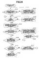
- step S 92assume that it is found at step S 92 that any connection is changed while the system is in operation, and that it is found at step S 93 that all the connections to the connected apparatuses are discontinued. In this case, control is returned to the step S 73 described in FIG. 33 . Connections are recognized again. If it is found at step S 94 that any connection is incorrect, the incorrect connection is indicated using the observation monitor 216 at step S 95 . At the same time, voice is uttered to report the fact. Control is then returned to step S 91 , and it is checked if the connection has been corrected.
- step S 142If it is found at step S 142 that a connected apparatus is of the same model as the apparatus, option information specified in the apparatus ID number of the apparatus that has initiated this procedure is modified at step S 143 .
- the option informationis set to a value different from that specified in the apparatus ID number of the connected apparatus.
Landscapes
- Physics & Mathematics (AREA)
- General Physics & Mathematics (AREA)
- Engineering & Computer Science (AREA)
- Automation & Control Theory (AREA)
- Measuring And Recording Apparatus For Diagnosis (AREA)
Abstract
Description
The present application refers to Japanese Patent Application No. 11-272792 filed on Sep. 27, 1999, Japanese Patent Application No. 11-282004 filed on Oct. 1, 1999, Japanese Patent Application No. 11-304281 filed on Oct. 26, 1999, and Japanese Patent Application No. 2000-269180 filed on Sep. 5, 2000, which are the basics of the present application, and benefits from the basic patent applications.
Field of the Invention and Description of the Related Art
The present invention relates to a medical apparatus supporting system for providing a maintenance service for medical equipment.
In recent years, microcomputers have been used to drive and control medical equipment. When a program installed in the microcomputer and described how to drive and control medical equipment contains a bug or when the program must be updated through modification or extension, a maintenance serviceperson visits a site in which the medical equipment is installed. The serviceperson dismounts a printed-circuit board realizing the microcomputer having the program installed therein, and brings it with her/his back to a predetermined maintenance service center. Otherwise, the serviceperson updates the program using a reprogramming apparatus at the site in which the printed-circuit board is dismounted.
However, it is time-consuming and skilled labor to dismount a printed-circuit board concerned from medical equipment or a ROM included in a microcomputer and used to storea program. Under the circumstances, Japanese Unexamined Patent Application Publication No. 8-179986 has proposed a method of writing a new program, or rewriting or updating the program without the necessity of dismounting the microcomputer or ROM.
Moreover, Japanese Unexamined Patent Application Publication No. 7-132121 has proposed a method of displaying information on a centralized display panel to report the information to a surgeon or an operator of medical equipment. Specifically, according to the method, when a plurality of pieces of medical equipment is used to extend medical conducts, information indicating that each piece of medical equipment has been driven under preset conditions is displayed on the concentrated display panel. Moreover, assume that certain medical equipment has been driven to enter a state different from a preset driven state, or more particularly, medical equipment fails or acts under conditions different from preset conditions. In this case, an error indication meaning that an abnormality has occurred in the medical equipment is displayed in an area on the display panel allocated to the medical equipment. Thus, the state of medical equipment is reported to a surgeon or an operator of medical equipment.
The Japanese Unexamined Patent Application Publication No. 8-179986 has proposed a method of writing, rewriting, or updating a program stored in a ROM included in a microcomputer even after the microcomputer or ROM is mounted on a printed-circuit board included in medical equipment or any other electronic equipment. However, for writing, rewriting, or updating the program stored in the ROM included in the microcomputer, a maintenance serviceperson has to visit the installation site of the medical equipment. The owner of the medical equipment cannot use the medical equipment until the serviceperson completes writing, rewriting, or updating the program. It takes too much time until the medical equipment becomes reusable.
Moreover, according to the Japanese Unexamined Patent Application Publication No. 7-132121, if certain medical equipment included in a surgical system composed of a plurality of pieces of medical equipment malfunctions, an error indication is displayed on the display area on the display panel allocated to the medical equipment. Thus, it is reported to a surgeon or an operator of medical equipment that the medical equipment has malfunctioned. However, although the malfunctioning medical equipment may be specified, it is impossible to discover the contents of the malfunction and locate a defective component of the medical equipment causing the malfunction. For this reason, a maintenance serviceperson must visit the installation site of the medical equipment to locate the defective component thereof causing the malfunction and repair the defective component. The user of the medical equipment cannot therefore use the medical equipment for a long period of time from the occurrence of the malfunction to the resolution thereof.
An object of the present invention is to provide a medical apparatus supporting system making it possible to rewrite or update a program stored in a storage device such as a ROM, in which a program for instructing a microcomputer included in medical equipment how to operate is stored, by extending remote control over a communication line.
Another object of the present invention is to provide a medical apparatus supporting system for, when medical equipment malfunctions, reporting malfunction information to a user of the medical equipment by displaying the malfunction information, and transmitting the malfunction information to a maintenance service provider over a communication line so that a maintenance service can be provided immediately.
A medical apparatus supporting system consists mainly of a plurality of pieces of medical equipment, a reprogrammable storage device, a reprogramming control unit, and a computer. The plurality of pieces of medical equipment has a communication facility. The reprogrammable storage device is included in each of the plurality of pieces of medical equipment. A program used to drive and control each piece of medical equipment is stored in the storage device. The reprogramming control unit reprograms the storage device. The computer has a communication facility for communicating data over an information communication line, and transmits a rewriting/updating program with which a program stored in the storage device is rewritten or updated.
The rewriting/updating program with which the program stored in the storage device included in each piece of medical equipment is rewritten or updated is transmitted to each piece of medical equipment over the information transmission line under control of the computer. The reprogramming control unit rewrites or updates the program stored in the storage device using the received rewriting/updating program. Thus, the program can be rewritten or updated remotely using the computer located away from the pieces of medical equipment.
FIG. 1 to FIG. 3 are concerned with the first embodiment of the present invention;
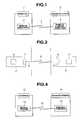
FIG. 1 is a block diagram showing the overall configuration of the first embodiment of the present invention;
FIG. 2 is a block diagram showing a practical configuration of the first embodiment;
FIG. 3 is a flowchart describing actions to be performed in the first embodiment;
FIG. 4 to FIG. 7 are concerned with the second embodiment of the present invention;
FIG. 4 is a block diagram showing an overall configuration of a medical apparatus supporting system in accordance with the second embodiment;
FIG. 5 is a block diagram showing in detail the second embodiment;
FIG. 6 is a block diagram showing a configuration of a local assessment means included in medical equipment employed in the second embodiment;
FIG. 7 is a flowchart describing actions to be performed in the second embodiment;
FIG. 8A to FIG. 9 are concerned with the third embodiment of the present invention;
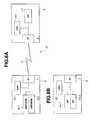
FIG. 8A is a block diagram showing a configuration of a medical apparatus supporting system in accordance with the third embodiment;
FIG. 8B is a block diagram showing a configuration of medical equipment employed in a variant;
FIG. 9 is a flowchart describing actions to be performed in the third embodiment;
FIG. 10 to FIG. 12 are concerned with the fourth embodiment of the present invention;
FIG. 10 is a block diagram showing an example of a configuration of medical equipment employed in the fourth embodiment;
FIG.11A and FIG. 11B describe facilities to be invoked for normal actions and facilities to be invoked for necessary minimum actions;
FIG. 12 is a flowchart describing actions to be performed in the fourth embodiment;
FIG. 13 to FIG. 15 are concerned with the fifth embodiment of the present invention;
FIG. 13 shows a medical apparatus supporting system in accordance with the fifth embodiment;
FIG. 14 is a block diagram showing a practical configuration of the fifth embodiment;
FIG. 15 is a flowchart describing actions to be performed in the fifth embodiment;
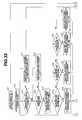
FIG. 16 is a flowchart describing actions to be performed in the sixth embodiment of the present invention;
FIG. 17 shows configurations of pieces of medical equipment a cable connection between which is checked;
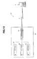
FIG. 18 shows an overall configuration of an endoscopic medical system utilizing an endoscope and having a facility for judging if a cable is disconnected;
FIG. 19 is an explanatory diagram showing connections among a system controller, a TV camera controller, and a light source unit shown in FIG. 18;
FIG. 20 is a conceptual diagram of a control unit incorporated in the system controller or any other apparatus shown in FIG. 18;
FIG. 21 shows the appearance of a cable to explain the structure thereof;
FIG. 22 is an explanatory diagram concerning a monitor screen indicating that a communication cable is disconnected;
FIG. 23 is an explanatory diagram concerning a monitor screen indicating that a data transmission cable is disconnected;
FIG. 24 is a flowchart describing a procedure of checking if a cable is disconnected;
FIG. 25 is a flowchart describing the sequel of the procedure described in FIG. 24;
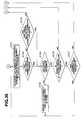
FIG. 26 shows an overall configuration of an endoscopic medical system different from the configuration shown in FIG. 18;
FIG. 27 is a conceptual explanatory diagram showing an endoscopic medical system capable of preventing failure of apparatuses constituting the system when a cable is disconnected;
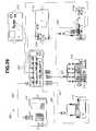
FIG. 28 shows a used state of a medical system included in a connected apparatus identification system;
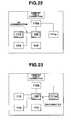
FIG. 29 shows connections of a system included in the medical system shown in the left-hand part of FIG. 28;
FIG. 30 shows connections among a system controller, an endoscope camera unit, and a light source unit included in the system shown in FIG.29 and provided with communication terminals;
FIG. 31 shows connections made when two mutually-identical endoscope camera units are used with the light source unit shown in FIG. 30 replaced with the endoscope camera unit;
FIG. 32 shows the meanings of an apparatus ID number whose assignment is described in conjunction with FIG.30 and FIG. 31;
FIG. 33 is a first flowchart describing a procedure of recognizing a connection of the system controller shown in FIG. 28;
FIG. 34 is a second flowchart describing the procedure of recognizing a connection of the system controller shown in FIG. 28;
FIG. 35 is a first flowchart describing a procedure of recognizing a connection of an apparatus other than the system controller shown in FIG. 28;
FIG. 36 is a second flowchart describing the procedure of recognizing a connection of apparatus other than the system controller shown in FIG. 28; and
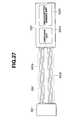
FIG. 37 is an explanatory diagram for explaining transmission from the medical system shown in FIG. 28 to an external system.
Referring to FIG. 1 to FIG. 3, the first embodiment of the present invention will be described below.
As shown in FIG. 1, a medical apparatus supporting system in accordance with the present embodiment includes ahospital 1 or any other medical institution in whichmedical equipment 2 that is a surgical system using an electronic endoscope is installed. Themedical equipment 2 is composed of an electronic endoscope, an endoscope light source unit, a lesion display monitor for a surgeon, an image processing unit, a recording unit, a pneumoperitoneum unit, and a treatment appliance. On the other hand, aremote control computer 4 is installed in amanufacturer 3 for manufacturing and/or selling themedical equipment 2 to be installed in thehospital 1, or providing a maintenance service for the medical equipment. Themedical equipment 2 in thehospital 1 is linked to theremote control computer 4 in themanufacturer 3 over acommunication line 5. Thecommunication line 5 may be realized with wire communication, for example, a public telephone line or a leased telephone line, or radiocommunication using radio waves.
As shown in FIG. 2, themedical equipment 2 includes aROM 6 in which a program for instructing a microcomputer included in themedical equipment 2 to control driving actions performed in themedical equipment 2 is stored. Acommunication cable 8 is connected to theROM 6 via aninterface 7 for interfacing the ROM with thecommunication line 5. TheROM 6 is realized with an electrically reprogrammable nonvolatile memory, for example, an electrically erasable programmable ROM (EEPROM) or a flash memory.
On the other hand, theremote control computer 4 installed in themanufacturer 3 includes a program storage means (a hard disk in practice)11 in which a rewriting/updating execution program and a new rewriting/updating program are stored. Acommunication cable 10 is connected to the program storage means11 via aninterface 9 for interfacing the program storage means11 with thecommunication line 5.
Rewriting or updating of a program stored in theROM 6 in themedical equipment 2 with themedical equipment 2 andremote control computer 4 linked will be described in conjunction with FIG.3.
Assuming that it becomes necessary to rewrite or update the program stored in theROM 6 included in themedical equipment 2 installed in thehospital 1, themanufacturer 3 contacts thehospital 1 to report the necessity of rewriting or updating the program (step S1). In response to the report of the necessity of rewriting or updating the program sent from themanufacturer 3, thehospital 1 connects thecommunication cable 8 of themedical equipment 2 to the predetermined communication line5 (step S2).
Thereafter, in thehospital 1, a ROM Version Upgrading button or switch (hereinafter a version upgrading button), which is not shown, included in themedical equipment 2 is pressed. A rewriting/updating execution program that is not shown is read from theROM 6 in themedical equipment 2, and then run (step S3). The rewriting/updating execution program stored in theROM 6 in themedical equipment 2 is run at step S3, whereby identification (hereinafter ID) information with which themedical equipment 2 is identified and a telephone number are transmitted (step S4).
Themanufacturer 3 collates the ID information and telephone number, which are sent from thehospital 1 at step S4, with a customer/installed medical equipment list, which is not shown, stored in theremote control computer 4. If the ID information and telephone number are consistent with those written in the list theremote control computer 4 in themanufacturer 3 is connected to the communication line5 (step S5). After themedical equipment 2 in thehospital 1 is linked to theremote control computer 4 in the manufacturer at step S5, themanufacturer 3 transmits a new rewriting/updating program, with which an old program is rewritten or updated, over thecommunication line 5 according to the rewriting/updating execution program installed in the remote control computer4 (step S6).
According to the rewriting/updating execution program transmitted from themanufacturer 3, the new rewriting/updating program is used to rewrite or update an old program stored in theROM 6 included in themedical equipment 2 in the hospital1 (step S7). When the new rewriting/updating program has been stored, theinterfaces hospital 1 andmanufacturer 3 respectively disconnected from thecommunication line 5. Hereinafter, thehospital 1 can drive and control themedical equipment 2 according to the new rewriting/updating program stored theROM 6.
Conventionally, a maintenance serviceperson visits thehospital 1, dismounts a ROM from medical equipment, brings it back with him/her, and stores a new rewriting/updating program in the ROM. Otherwise, the rewriting/updating program is stored in order to rewrite an old program at the installation side of the medical equipment. In contrast, according to the present embodiment, a new rewriting/updating program with which an old program is rewritten or updated can be transmitted from a remote control computer installed in a manufacturer to medical equipment installed in a hospital in order to rewrite an old program. Consequently, a program can be rewritten immediately by utilizing a time zone during which the medical equipment is unused in the hospital.
Iteratively, when a processing program must be rewritten or updated, the program stored in a ROM in medical equipment can be rewritten or updated over a communication line linking a manufacturer and a medical institution at which the medical equipment is installed. Even if the medical institution is located remotely away from the manufacturer, the program stored in the ROM in the medical equipment can be efficiently rewritten or updated with the medical equipment kept installed in the medical institution during a time zone convenient to the medical institution. This contributes to improvement of processing efficiency.
Next, the second embodiment of the present invention will be described with reference to FIG. 4 to FIG.7.
As shown in FIG. 4, according to the second embodiment, amedical system 13 installed in ahospital 12 and asupport computer 15 installed in amanufacturer 14 for manufacturing and/or selling themedical system 13 or providing a maintenance service are linked over acommunication line 16. This results in a medical apparatus supporting system.
Themedical system 13 installed in thehospital 12 has, as shown in FIG. 5, a plurality of pieces ofmedical equipment system controller 19 overcommunication cables centralized display panel 21 that is a display means is connected to thesystem controller 19 over acommunication cable 20a, and acentralized control panel 22 that is a display input means including a display means is connected thereto over acommunication cable 20b.
When thecentralized control panel 22 is used to enter a driving instruction to be input to the pieces ofmedical equipment 17ato17d, thesystem controller 19 sorts instructions entered at thecentralized control panel 22. Thesystem controller 19 then transmits them to the respective pieces ofmedical equipment 17ato17dover thecommunication cables 18ato18d. The pieces ofmedical equipment 17ato17dare driven under control of microcomputers included in the pieces ofmedical equipment 17ato17d. The driven states of the pieces ofmedical equipment 17ato17dare transmitted to thesystem controller 19 over thecommunication cables 18ato18d, and displayed on thedisplay panel 21 in association with the pieces ofmedical equipment 17ato17d.
The pieces ofmedical equipment 17ato17dthat are surgical systems based on an electronic endoscope are each composed of, for example, an electronic endoscope, an endoscope light source unit, a lesion display monitor for a surgeon, an image processing unit, a recording unit, a pneumoperitoneum unit, and a treatment appliance. The pieces ofmedical equipment 17ato17deach includes built-in printed-circuit boards that realize a facility for driving and controlling medical equipment. The printed-circuit boards also realize a local assessment facility for monitoring a driven and controlled state and locally assesses it to judge whether the driven and controlled state falls within a predetermined range or falls outside the predetermined range to correspond to an abnormal or incorrect state.
The local assessment facility is realized with each built-in printed-circuit board included in each of the pieces ofmedical equipment 17ato17d. For example, themedical equipment 17aincludes, as shown in FIG. 6, a microcomputer (hereinafter CPU)27 and aROM 28. TheCPU 27 drives and controls printed-circuit boards which are included in themedical equipment 17aand on which a driving control circuit or the like is mounted. A processing program for instructing theCPU 27 how to act is stored in theROM 28. The program and various control instructions are transferred between theCPU 27 andROM 28 over a bus. TheCPU 27 andROM 28 are connected to aconduction sense controller 25 and an abnormalsignal sense controller 26 over the bus.
When the power supply of themedical equipment 17ais turned on, theconduction sense controller 25 monitors a driving signal applied by a driving control circuit mounted on any of the printed-circuit boards driven and controlled by theCPU 27 according to the programs stored in theROM 28. Theconduction sense controller 25 checks if the driving signal assumes a predetermined voltage level. If the driving signal applied by the driving control circuit is lower or higher than the predetermined voltage level, an error signal is produced. The abnormalsignal sense controller 26 monitors a processing signal produced by each driving control circuit according to the program read from theROM 28 while theCPU 27 is controlling the driving control circuit. The abnormalsignal sense controller 26 checks if the produced processing signal is a predetermined processing signal. If the produced processing signal is not the predetermined one, an error signal is produced.
If theconduction sense controller 25 or abnormalsignal sense controller 26 senses an abnormal driving signal produced by a driving control circuit mounted in any printed-circuit board included in themedical equipment 17aor an abnormal processing signal, an error signal is fed to acontroller 24. Thecontroller 24 produces a display signal according to the contents of an abnormality represented by the fed error signal and an identification (hereinafter ID) number assigned to a printed-circuit board on which the abnormality has occurred, and outputs the display signal to anoutput controller 23. Theoutput controller 23 drives and controls thecentralized display panel 21 according to the display signal fed from thecontroller 24, and identifies and displays the ID number of the printed-circuit board on which the abnormality has occurred and the abnormality.
An error information detection facility realized with theconduction sense controller 25 and abnormalsignal sense controller 26 is included in each of the pieces ofmedical equipment 17ato17d. Specifically, an instruction is entered at thecentralized control panel 22, and thesystem controller 19 controls driving of the pieces ofmedical equipment 17ato17daccording to the entered instruction. Information of the driven states of the pieces ofmedical equipment 17ato17dis output to thecentralized display panel 21 via thesystem controller 19 and displayed in association with the pieces ofmedical equipment 17ato17d.
Assume that an abnormality occurs in any of the pieces ofmedical equipment 17ato17d, for example, assume that the voltage level of a driving signal fed from a drive circuit mounted on any of the printed-circuit boards included in themedical equipment 17ais abnormal. In this case, theconduction sense controller 25 included in themedical equipment 17asenses the abnormality. A voltage level error signal is then output to thecontroller 24 included in themedical equipment 17a. Thecontroller 24 in themedical equipment 17aproduces an error indication signal representing a voltage level error indication and the ID information of the printed-circuit board on which the abnormal voltage level has occurred, and outputs the error indication signal to theoutput controller 23. Theoutput controller 23 controls thecentralized display panel 21 to display the contents of the abnormality and the ID information of the abnormal printed-circuit board according to the error indication signal.
For example, assume that a processing signal output from a drive circuit mounted on any of the printed-circuit boards included in themedical equipment 17cis abnormal. If the abnormalsignal sense controller 26 included in themedical equipment 17csenses the abnormality, it produces a processing signal error signal. The processing signal error signal is output to thecontroller 24 in themedical equipment 17c. Based on the signal processing error signal, thecontroller 24 in themedical equipment 17cproduces an error indication signal representing a signal processing error indication and the ID information of the printed-circuit board on which abnormal signal processing has occurred. The error indication signal is output to theoutput controller 23. Theoutput controller 23 controls thecentralized display panel 21 to display the contents of the abnormality and the ID information of the abnormal printed-circuit board according to the error indication signal.
Consequently, the operators of the pieces ofmedical equipment 17ato17dcan always monitor the driven states of the medical equipment at the sight of the indications displayed on thecentralized display panel 21. If the driven state of any medical equipment is abnormal, not only the abnormal medical equipment can be specified but also an abnormal printed-circuit board in the medical equipment can be identified. The information of the abnormality is transmitted to themanufacturer 14 over thecommunication line 16, whereby a request for a maintenance service can be immediately issued to themanufacturer 14. Moreover, themanufacturer 14 can immediately locate an abnormal device mounted on the printed-circuit board and make preparations for repair of the abnormal device.
Next, actions to be performed from the instant abnormal medical equipment is found to the instant a request for a maintenance service is issued to themanufacturer 14 will be described in conjunction with FIG.7.
Themedical system 13 is installed in a predetermined therapeutic place within thehospital 12. The power supply of medical equipment is turned on (step S11). A driving control instruction for instructing driving and control of the pieces ofmedical equipment 17ato17dis entered at thecentralized control panel 22. The pieces ofmedical equipment 17ato17dare driven in response to the instruction. The driven states of the medical equipment are displayed on thecentralized display panel 21, whereby the pieces of medical equipment used to perform treatment are thought to have entered the usable states (step S12). When the pieces of medical equipment have entered the usable states at step S12, theconduction sense controller 25 executes conduction sensing (step S13). Specifically, theconduction sense controller 25 senses an abnormal driving signal fed from a drive circuit mounted on any of the built-in printed-circuit boards included in the pieces ofmedical equipment 17ato17d. Moreover, the abnormalsignal sense controller 26 executes abnormal signal sensing (step S14) to sense an abnormal processing signal output from a drive circuit mounted on any of the built-in printed-circuit boards included in the pieces ofmedical equipment 17ato17d.
If an abnormality is sensed at either of step S13 and step S14, thecontroller 24 judges whether the contents of the abnormality are abnormal conduction or an abnormal signal. Thecontroller 24 then produces error indication information representing the contents of the abnormality and the ID information of the abnormal printed-circuit board (step S16). The error indication information is converted into an error indication signal by the output controller23 (step S16), and fed to thecentralized display panel 21. Consequently, the abnormal one of the pieces ofmedical equipment 17ato17d, the contents of the abnormality, and the ID information of the abnormal printed-circuit board are indicated using the centralized display panel21 (step S17).
While referencing the error indication displayed on thecentralized display panel 21, a surgeon or an operator of medical equipment selects and presses a Support Service button, which is not shown, formed on the centralized control panel22 (step S18). Themedical system 13 is then linked to thesupport computer 15 installed in themanufacturer 14 over thecommunication line 16, and transmits ID information representing the hospital name, medical equipment, and printed-circuit board in which the abnormality has occurred, and the contents of the abnormality
In response to the abnormality information sent from thehospital 12, themanufacturer 14 returns a reply, which indicates that the abnormality information has been received and a request for support has been granted, to thehospital 12. Thus, thehospital 12 has completed requesting the manufacturer to give support (step S20). Themanufacturer 14 procures various parts required for providing a repair service to resolve the abnormality, assigns a serviceperson to the repair service job, estimates the time required for the repair service, and reports the estimate to the hospital12 (step S21).
As mentioned above, according to the second embodiment, the driven and controlled state of a component of medical equipment, which is driven by a driving control circuit mounted on each printed-circuit board included in each piece of medical equipment included in a medical system, is sensed, and indicated using a display panel. A surgeon or an operator can therefore grasp the driven state of medical equipment during use of the medical equipment, and continue treatment at ease.
If medical equipment should become abnormal, the abnormal medical equipment and the contents of the abnormality are indicated using the display panel. Once the abnormal medical equipment alone is replaced with a new one, treatment can be continued. As for the abnormal medical equipment, occurrence of an abnormality can be reported immediately to a manufacturer over a communication line, and a request for a repair service can be issued immediately to the manufacturer. The ID information representing the abnormal medical equipment, the contents of the abnormality, and an abnormal printed-circuit board is transmitted to the manufacturer together with the request for a repair service. Therefore, the manufacturer can predict a cause of the abnormality, procure parts necessary for the repair service, and estimate the time required for the repair service. Consequently, the repair service can be provided immediately.
Each printed-circuit board for realizing a facility included in medical equipment is designed to also realize a local assessment facility. The medical equipment is linked to a medical equipment repair service provider over a communication line. Thus, if the medical equipment should become abnormal, the contents of the abnormality are indicated using a display panel. The abnormal action of the medical equipment can be coped with immediately. Beside, the abnormality information is transmitted to the repair service provider over the communication line. Consequently, the cause of the abnormality can be predicted, and a repair service can be provided immediately.
Next, the third embodiment of the present invention will be described with reference to FIG. 8A to FIG.9.
The configuration of a medical apparatus supporting system in accordance with the present embodiment is the same as that shown in FIG.1. Moreover, the configuration shown in FIG. 8A corresponds to the configuration of the medical apparatus supporting system shown in FIG.2.
A medicalapparatus supporting system 41 shown in FIG. 8A consists mainly ofmedical equipment 2 having a communication facility and aremote control computer 4 linked to themedical equipment 2 over acommunication line 5 over which information is transmitted.
The medicalapparatus supporting system 41 includes a plurality of program storage means in which a program for instructing themedical equipment 2 how to act is stored, or more particularly, two ROMs6-1 and6-2 as shown in FIG.8A.
Themedical equipment 2 includes aCPU 42 connected to acommunication interface 7 and the two ROMs6-1 and6-2. TheCPU 42 controls the actions of themedical equipment 2 according to the program stored in the ROM6-1 or ROM6-2. The programs stored in the ROM6-1 and ROM6-2 are rewritten under control of theCPU 42. The ROM6-1 and ROM6-2 are realized with, for example, nonvolatile electrically reprogrammable EEPROMs (or flash memories).
Theremote control computer 4 includes aninterface 9 connected to thecommunication line 5 and aCPU 43 connected to a program storage means (hard disk)11 in which a rewriting program is stored. TheCPU 43 controls transmission of the program used to rewrite an old program. An operation program for instructing theCPU 43 how to act is also stored in thehard disk 11.
According to the present embodiment, at least two memory means are included as memory means in which a program to be transmitted is stored. Even if transmission of data over thecommunication line 5 is not performed smoothly a program can be rewritten reliably.
According to the first embodiment, a rewriting/updating program with which an old program is rewritten or updated is transmitted from theremote control computer 4 to themedical equipment 2 in thehospital 1 over thecommunication line 5. Thus, a program stored in theROM 6 is rewritten or updated. However, the quality of transmitted data may be deteriorated in some states of thecommunication line 5.
According to the present embodiment, the plurality of ROMS, that is, the ROM6-1 and ROM6-2 are, as mentioned above, employed so that a program can be rewritten or updated more reliably.
To be more specific, data stored in one of the plurality of ROMs, that is, one of the ROM6-1 and ROM6-2 is rewritten based on whether received data (rewriting program) is odd-numbered or even-numbered data. If an old program is not rewritten normally with the first program (for example, at an odd-numbered program), the program stored in the other one of the ROM6-1 and ROM6-2 is rewritten using a program received next (for example, at an even-numbered program).
As the program storage means included in themedical equipment 2, two hard disks44-1 and44-2 shown in FIG. 8B may be substituted for the ROMs6-1 and6-2 shown in FIG.8A.
Next, actions to be performed to rewrite a program will be described with reference to FIG.9.
At step S31, with themedical equipment 2 andremote control computer 4 linked over thecommunication line 5, a rewriting program stored in thehard disk 11 in theremote control computer 4 is transmitted to theCPU 42 in themedical equipment 2 under control of theCPU 43.
TheCPU 42 judges at step S32 whether a parameter m indicating the number of times of transmission is an integral (n) multiple of 2 (m−2n), that is, an even number. If the transmission is the first transmission, m=1. Control is therefore passed to step S33. If the transmission is the second transmission (m=2), control is passed to step S35.
At step533, theCPU 42 rewrites a program stored in the ROM6-1 using the received data (first program). At the next step S34, theCPU 42 judges whether rewriting has terminated. If the rewriting has terminated normally, this procedure is terminated. If it is judged that the rewriting has not terminated normally, m is incremented by one at step S36 (m=2). Since the stored program has been rewritten incorrectly, a request for transmission of the program is retransmitted to theCPU 43 in the remote control computer4 (step S37). Control is then returned to step S31.
If it is judged at step S32 that an even number is specified for m, control is passed to step S35. TheCPU 42 rewrites the program stored in the ROM6-2 using the received data (second program). At the next step S34, theCPU 42 judges whether rewriting has terminated normally. If the rewriting has terminated normally, the procedure is terminated. If it is judged that the rewriting has not terminated normally, m is incremented by one (step S36). Since the stored program has been rewritten incorrectly, a request for program transmission is retransmitted to theCPU 43 in theremote control computer 4. Control is then returned to step S31.
Even when the state of transmission over thecommunication line 5 is unsatisfactory, transmission of a rewriting program is repeated until an old program is rewritten correctly. Consequently, an old program can be rewritten reliably.
The procedure described in FIG. 9 is associated with the configuration shown in FIG.8A. When the two hard disks44-1 and44-2 are adopted as shown in FIG. 8B on behalf of the ROMs6-1 and6-2, the ROM6-1 in FIG. 9 should be read as the hard disk44-1, and the ROM6-2 should be read as the hard disk44-2.
Instead of alternately rewriting (updating) programs stored in the ROMs, a program stored in one of the ROMs (for example, the ROM6-1) or one of the hard disks (for example the hard disk44-1) may be rewritten (updated). When program rewriting (updating) becomes necessary because the version of a program is upgraded, the program stored in the. other ROM (for example, the ROM6-2) or the other hard disk (for example, the hard disk44-2) may be rewritten (updated).
Next, the fourth embodiment of the present invention will be described with reference to FIG. 10 to FIG.12.
Medical equipment included in a medical apparatus supporting system in accordance with the present embodiment is nearly identical to the one shown in FIG.8A. However, a fixed program (auxiliary program) incapable of being rewritten and used to control minimum necessary facilities shown in FIG.11(B) is stored in the ROM6-2.
On the other hand, the ROM6-1 is a reprogrammable ROM similarly to the one shown in FIG. 8A, and realized with an EEPROM or the like.
According to the present embodiment, the medical equipment can be activated with the facilities shown in FIG. 11A invoked normally or with the minimum necessary facilities shown in FIG. 11B invoked.
In practice, the facilities to be invoked normally include medical equipment monitoring46a, centralizedmedical equipment display 46b, centralizedmedical equipment control 46c, and comprehensive medical equipment setting46d. The minimum-necessary auxiliary facilities include the medical equipment monitoring46aand centralizedmedical equipment control 46c.
A normal-operation program stored in the ROM6-1 describes the facilities to be invoked normally. According to the present embodiment, normally, the program stored in the ROM6-1 alone is rewritten with a received program. If the rewriting is not performed normally, the fixed program stored in the ROM6-2 is invoked to activate the medical equipment.
Actions to be performed according to the present embodiment will be described with reference to FIG.12.
Themedical equipment 2 is activated while being linked to theremote control computer 4 over thecommunication line 5. At step S41, a rewriting program stored in thehard disk 11 is transmitted from theremote control computer 4 to theCPU 42 in themedical equipment 2 under control of theCPU 43.
At step S42, theCPU 42 rewrites the normal-operation program using the received program. In practice, the program stored in the ROM6-1 is rewritten. It is judged at step S43 whether the rewriting has terminated normally. If the rewriting has terminated normally, the procedure is terminated. If the rewriting has not terminated normally, control is returned to step S44. The settings of themedical equipment 2 are altered in order to invoke the fixed or emergency program stored in the ROM6-2. In other words, although themedical equipment 2 is normally activated with the program stored in the ROM6-1 when the power supply thereof is turned on, the setting of theCPU 42 is altered to read the fixed program stored in the ROM6-2 at step S44. The procedure described in FIG. 12 is then terminated.
According to the present embodiment, even if a program should not be able to be rewritten correctly through remote transmission, medical equipment can be activated with a fixed program. The medical equipment can therefore act with at least the minimum necessary facilities invoked.
The program stored in the ROM6-2 cannot be rewritten remotely. Alternatively, a lid or the like may be formed in themedical equipment 2 and opened in order to replace the ROM6-2 with another so as to upgrade the version of the program.
Moreover, the ROM6-2 may be a read-only memory (ROM) that is not reprogrammable, or may be a reprogrammable EEPROM that is write-protected.
Next, the fifth embodiment of the present invention will be described with reference to FIG. 13 to FIG.15.
A medicalapparatus supporting system 51 shown in FIG. 13 has amedical system 52 and theremote control computer 4 linked over thecommunication line 5. Themedical system 52 consists mainly of a plurality of pieces ofmedical equipment system controller 54 for controlling the plurality of pieces ofmedical equipment system controller 54 is linked to theremote control computer 54 over thecommunication line 5.
FIG. 14 shows the internal configuration of the medical apparatus supporting system shown in FIG.13.
A rewriting program stored in afirst area 11ain thehard disk 11 incorporated in theremote control computer 4 is transmitted to thesystem controller 54 in themedical system 52 through theinterface 9 over thecommunication line 5 under control of theCPU 43.
TheCPU 43 receives a program returned from thesystem controller 54, and stores it in asecond area 11bin thehard disk 11. TheCPU 43 then reads the rewriting program from thefirst area 11aand the returned program from thesecond area 11b, and collates the programs in acollation register 43 incorporated therein.
By the way, thesystem controller 54 consists mainly of aninterface 61, aninterface 62, aCPU 63, and a hard disk (or a memory such as a RAM)64. Theinterface 61 is connected to thecommunication line 5. Theinterface 62 enables transfer to or from themedical equipment 2A and others over cables. TheCPU 63 controls data transfer to or from theremote control computer 4 and data transfer to or from themedical equipment 2A and others, and manages themedical equipment 2A and others on a centralized basis. Thehard disk 64 serves as a storage device in which an operation program instructing theCPU 3 how to act or a transferred program is stored temporarily.
Moreover, themedical equipment 2A has the same configuration as the one shown in FIG. 8A, and includes two reprogrammable (EEP) ROM6-1 and ROM6-2. Themedical equipment 2B and others also have the same configuration.
According to the present embodiment, as described in conjunction with FIG. 15, a program sent from theremote control computer 4 is received in order to rewrite a program stored in one of the plurality of memory means included in themedical equipment 2A or the like. The rewritten program is returned to theremote control computer 4. TheCPU 43 in theremote control computer 4 collates the returned program with the transmitted program. If the programs are mutually inconsistent, the program is retransmitted.
If the programs are mutually consistent, the medical equipment is activated using the program. It is judged if the medical equipment acts normally. If the medical equipment acts normally, the settings of the medical equipment are altered so that the medical equipment will be activated with the rewritten program. The rewritten program is then copied to the other memory means in order to rewrite the program stored in the other memory means.
If it is judged that the medical equipment acts abnormally, the medical equipment will be activated using the program stored in the other memory means.
Next, actions to be performed in the present embodiment will be described with reference to FIG.15.
The power supply of theremote control computer 4 is turned on, and theremote control computer 4 is activated. A step S51, a rewriting program is transmitted from theCPU 43 in theremote control computer 4 to thesystem controller 54 in themedical system 52 over thecommunication line 5.
At this time, theCPU 43 appends information, with which the medical equipment2I (where I denotes A, B, or C) to be reprogrammed is specified, to the rewriting program.
If the version of software included in the medical equipment2I must be upgraded, thesystem controller 54 may transmit a request signal, which represents a request to upgrade the version of software included in the medical equipment2I, to theremote control computer 4. Theremote control computer 4 may then transmit the software program of the upgraded version to thesystem controller 54.
At step S52, theCPU 63 in thesystem controller 54 temporarily stores the received program in thehard disk 64, transfers it to the medical equipment2I to be reprogrammed at a proper bit rate, and sends a rewriting signal to the medical equipment2I. The medical equipment2I (CPU 42 in the medical equipment) rewrites the first program stored in one (for example, the ROM6-1) of the two ROMs6-1 and6-2 included in the medical equipment2I.
After the rewriting is completed, theCPU 42 returns the first program to theremote control computer 4 via thesystem controller 54 at step S53.
At step S54, theCPU 43 in theremote control computer 4 stores the returned program in thesecond area 11bin thehard disk 11. TheCPU 43 then uses the collation register43ato collate (compare) the first program stored in thesecond area 11bwith the rewriting program stored in thefirst area 11a.
If the results of collation reveal that the programs are mutually inconsistent, control is passed to step S51. The processing of steps S51 to S54 is repeated. If the results of collation reveal that the programs are mutually consistent, a signal indicating that the programs are mutually consistent is transmitted to thesystem controller 54.
At step S55, theCPU 42 in the medical equipment2I judges whether the first program runs normally. For example, the medical equipment2I is reset and provisionally set so that it will be activated with the first program. It is then judged whether the medical equipment acts normally.
If it is judged that the first program runs normally, the settings of the medical equipment is altered at step S56 so that the medical equipment will be activated with the first program. Control is then returned to step S57. If it is judged that the first program runs abnormally, the settings of the medical equipment are altered so that the medical equipment will be activated with the second program stored in the other ROM and not rewritten. Control is then passed to step S57.
At step S57, it is judged whether a program used to activate the medical equipment has been copied. If the program has been copied, the rewriting is terminated. If the program has not been copied, a program stored in one of the two ROMs6-1 and6-2 and used to activate the medical equipment is copied to the other ROM at step S59. Consequently, the program used to activate the medical equipment is stored in both the ROMs6-1 and6-2. The rewriting is then terminated.
Specifically, if the settings of the medical equipment are altered so that the medical equipment will be activated with a program stored in the ROM6-1, the program is copied to the ROM6-2 at step S59. If the settings of the medical equipment are altered so that the medical equipment will be activated with a program stored in the ROM6-2, the program is copied to the ROM6-1. Consequently, both the programs stored in the ROMs6-1 and6-2 are programs with which the medical equipment is activated normally.
According to the present embodiment, an actually rewritten program is returned to a program transmission source. It is then judged whether the rewritten program is consistent with a transmitted rewriting program. If he programs are mutually inconsistent, transmission of the rewriting program is repeated. Consequently, an old program can be reliably rewritten using a program that must be transmitted.
Moreover, it is judged if the rewritten program runs normally. If it is judged that the rewritten program runs abnormally, a program that has not been rewritten is used to activate the medical equipment. If the rewritten program contains a new bug, it runs abnormally. Even in this case, the program that has not been rewritten can be used to activate the medical equipment.
In this case, the program that has not been rewritten may contain a bug to be removed. For removing the bug, a rewriting program may be transmitted in order to upgrade the version of the program. However, the rewriting program may contain another bug and may be judged to run abnormally. In this case, the old program that has not been rewritten may be used to activate the medical equipment. However, since the bug is revealed in detail, although the facilities are limited in order to avoid the adverse effect of the bug, the medical equipment can be activated reliably.
Before program rewriting is terminated, copying is performed so that the programs stored in both the ROMs6-1 and6-2 will be programs that run normally. Even if it becomes necessary to resume the program rewriting in the future, the program rewriting can be carried out smoothly because the stored programs run normally.
As mentioned above, when a program installed in the medical equipment2I must be rewritten or updated, theCPU 42 included in the medical equipment2I controls rewriting or updating. Alternatively, theCPU 54 in thesystem controller 54 may control on a centralized basis rewriting or updating of programs stored in the ROM6-1 and ROM6-2 that are storage devices included in any piece of medical equipment2I.
In thesystem 51 shown in FIG. 13 or FIG. 14, each piece of medical equipment2I may act as described in the flowchart of FIG.9. In this case, since thesystem controller 54 serving as a repeater is interposed between the medical equipment2I andremote control computer 4, a rewriting/updating program sent from theremote control computer 4 is subjected to summation check or the like and then stored in thehard disk 64 included in thesystem controller 54. If a bug is detected in the received program through the summation check, theremote control computer 4 may be asked to retransmit the program.
If the program can be received without occurrence of a bug, the program may be transmitted to the medical equipment2I in order to rewrite or update an old program installed in the medical equipment.
Next, the sixth embodiment of the present invention will be described with reference to FIG.16. According to the present embodiment, in the system shown in FIG. 8A, a rewriting program to which a local assessment program is appended is transmitted from theremote control computer 4 to themedical equipment 2. Themedical equipment 2 locally assesses itself before a program installed therein is rewritten.
Actions to be performed will be described with reference to the flowchart of FIG.16.
As described in FIG. 16, the medical equipment is activated with the power supply thereof turned on. At step S61, a rewriting program to which a local assessment program is appended is transmitted from theremote control computer 4 to themedical equipment 2.
At step S62, before the received program is used to rewrite an old program, theCPU 42 in themedical equipment 2 locally assesses hardware components thereof.
If the results of local assessment of hardware reveal that the hardware is no good or abnormal, it is reported to theremote control computer 4 at step S68 that an abnormality is found. The procedure is then terminated.
If the results of local assessment reveal that the hardware is OK, the received program is assessed locally at step S63. If the results of assessment reveal that the received program is no good, it is reported to theremote control computer 4 at step S68 that an abnormality is found.
In contrast, if it is judged that the received program is correct or OK, an old program stored in one of the ROMs (for example, the ROM6-1) is rewritten using the received program at step S64 (in FIG. 16, the first program is rewritten). After the rewriting is completed, the rewritten program is locally assessed at step S65.
If it is judged that the rewritten program is correct or OK, the settings of the medical equipment are altered so that the medical equipment will be activated with the rewritten program that is the first program. The rewriting is then terminated. In contrast, if it is judged that the rewritten program is no good, the settings of the medical equipment are altered so that the medical equipment will be activated with a second program stored in the other ROM6-2. The procedure is then terminated.
According to the present embodiment, before an old program is rewritten using a received rewriting program, hardware and the received program are assessed locally. After rewriting is completed, the rewritten program is assessed locally. Consequently, it can be assessed reliably whether themedical equipment 2 acts normally.
Moreover, if it is judged through local assessment that the rewritten program is no good, the settings of the medical equipment are altered so that the medical equipment will be activated with an old program stored in the other ROM and not rewritten. Even if program rewriting or updating fails, the medical equipment can be activated normally.
According to the present embodiment, the medical equipment2I is locally assessed on receipt of a rewriting program. The present invention is not limited to this mode. Alternatively, the medical equipment2I may be locally assessed in advance. If the results of local assessment reveal that the medical equipment acts normally, an old program installed in the medical equipment may be overwritten (rewritten) with the received program.
Incidentally, embodiments constructed by replacing part of an aforesaid embodiment with part of another aforesaid embodiment or combining the aforesaid embodiments shall belong to the scope of the present invention.
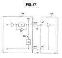
Whenequipment 71A andequipment 71B shown in FIG. 17 are connected overcables 72 to constitute a system, it may be judged whether thecables 72 are disconnected.
(A) In this case, a cable check mode may be defined independently of a normal operation mode.
In theequipment 71A, an impedance device Z1 is connected in series with an output port with a (transmission) buffer between them. The impedance device Z1 is made or broken by turning on or off a switch SW1 connected to both terminals of the impedance device. An impedance device Z2 is connected between output ports connected to the twocables 72, and made or broken by turning on or off a switch SW2.
The impedance devices Z1 and Z2 are designed to offer an impedance that is no negligible relative to an impedance (correct value when a cable is not disconnected) induced at each input port of theequipment 71B through which data sent through the output port of theequipment 71A is fed to theequipment 71B. Moreover, a (reception) buffer is connected to the input ports of the equipment B.
When the cable check mode is established, the switch SW1 is turned off and the switch SW2 is turned on. A voltage developed at a point TP1 is sensed. The voltage at the point TP1 varies depending on whether thecables 72 are disconnected. Therefore, whether thecables 72 are disconnected can be detected by checking the voltage at the point TP1.
(B) A means may be included for remotely switching the normal operation mode and cable check mode over a communication line (irrespective of wire communication or radiocommunication).
In this case, the switches SW1 and SW2 are realized with optical couplers.
As mentioned above, when the cable check mode is defined, a sensing means that works without hindering normal actions can be realized in order to judge whether a cable is disconnected.
Next, embodiments of the present invention to be described below are concerned with a medical system having a plurality of pieces of medical equipment interconnected over cables over which signals are transmitted. In the system as well as the system shown in FIG. 17, even if any cable is disconnected, the disconnection can be coped with efficiently. The embodiments are indented to provide a medical system making it possible to locate a disconnected cable without the necessity of visiting an installation site of a system or collecting the system to check a phenomenon. Moreover, the medical system makes it possible to obviate the necessity of time-consuming disconnection checking labor, reduce man-hours, shorten a maintenance time, and thus immediately provide a service for a user.
An endoscopicmedical system 81 shown in FIG. 18 has aTV camera controller 110a, alight source unit 111a, anelectric cautery 112, apneumoperitoneum unit 113, and a video tape recorder (hereinafter VTR)114 integrated into acart 120. These medical apparatuses are connected to asystem controller 100 for controlling the whole system on a centralized basis.
A surgical procedure to be performed under endoscopic observation requires many medical apparatuses that cannot be integrated into one cart. The medical apparatuses are therefore divided into a plurality of carts. According to the present embodiment, aside from the above medical apparatuses, aTV camera controller 110b, alight source unit 111b, and animage processing unit 115 are integrated into acart 130 and connected to arepeater unit 101. Therepeater unit 101 communicates with thesystem controller 100 over anindirect communication cable 102.
The medical apparatuses connected to thesystem controller 100 transmit data to thesystem controller 100 over communication cables. When thesystem controller 100 is communicating with the medical apparatuses, the medical apparatuses can be operated via thesystem controller 100 using acentralized operator panel 103 to be handled by a nurse or the like lying in an unsterilized area, or using aremote controller 104 to be handled by a surgeon lying in a sterilized area.
Video information produced by theTV camera controllers carts centralized display panels
Next, cable connections among the medical apparatuses will be described by taking for instance cable connections of thesystem controller 100 mounted in thecart 120 to theTV camera controller 110aandlight source unit 111a.
As shown in FIG. 19, each ofterminals 83 formed in thesystem controller 100,TV camera controller 110a, andlight source unit 111aincludes an inherent control terminal and acommunication terminal 82 which are plugged with acontrol cable 75.
Moreover, each ofterminals 83 formed in thesystem controller 100 andTV camera controller 110aincludes an inherent video terminal and acommunication terminal 82 which are plugged with avideo cable 90.
Furthermore, each ofterminals 83 formed in theTV camera controller 110aandlight source unit 111aincludes an inherent light adjustment terminal and acommunication terminal 82 which are plugged with alight adjustment cable 95.
Thecables medical apparatuses cable 84 shown in FIG.21. Thecable 84 has acommunication cable 85 and adata transmission cable 86. Thecables LEDs
Unique ID numbers are assigned to themedical apparatuses terminals 83 formed in the apparatuses.
As shown in FIG. 20, themedical apparatuses main control unit 150, acommunication control unit 151 for controlling communication, a signal transmission/reception unit 152 for transmitting or receiving signals, a dccomponent superposition unit 153, and a dccomponent sampling unit 154. A control device composed of these units transmits or receives a signal through theterminals 83 formed in each medical apparatus.
In the medical apparatuses including thesystem controller 100, the control device exerts the ability of each medical apparatus and executes a cable disconnection checking procedure to be described later. The control device thus checks the connected state of the cable84 (if thedata transmission cable 86 is connected to the inherent control terminal of each apparatus and thecommunication cable 85 is connected to the communication terminal thereof). When thecable 84 is connected to a proper medical apparatus, it is judged whether thedata transmission cable 86 andcommunication cable 85 included in thecable 84 are disconnected. The results of judgment are output and indicated using the observation monitor116aor116bserving as a disconnection reporting means. The control unit realizes such facilities as a connected state recognizing means and a disconnection judging means.
If thecommunication cable 85 of thecable 84 is disconnected, a message “No communication” or the like is, as shown in FIG. 22, displayed in a graphic showing cable connections among medical apparatuses on the observation monitor116aor116b. Moreover, a disconnected cable may be indicated using red or any other color different from the color of the other cables.
If thedata transmission cable 86 of thecable 84 is disconnected, a message “Disconnected” or the like is, as shown in FIG. 23, displayed in the graphic showing cable connections among medical apparatuses. Moreover, a disconnected cable may be indicated using red or any other color different from the color of the other cables.
Thesystem 81 is an endoscopic medical system having a plurality of medical apparatuses connected using signal transmission means. Thesystem 81 includes a connected state recognizing means, a disconnection judging means, and a disconnection reporting means. The connected state recognizing means recognizes the connected states of the signal transmission means. When the connected state recognizing means recognizes that the signal transmission means are connected to the associated medical apparatuses, the disconnection judging means judges whether any signal transmission means is disconnected. The disconnection reporting means reports disconnection information concerning the signal transmission means according to the results of judgment made by the disconnection judging means.
Next, a cable disconnection checking procedure will be described in conjunction with the flowcharts of FIG.24 and FIG.25. The procedure is executed with the power supply of an apparatus turned on. First, at step S101, it is judged whether the power supply of a connected apparatus is turned on. If the power supply of the connected apparatus is turned off, control is passed to step S102. A standby state is retained until the power supply of the connected apparatus is turned on.
If it is judged at step S101 that the power supply of the connected apparatus is turned on, control is passed to step S103. It is checked if a cable connection has been established. If any cable connection is not recognized, control is passed to step S104. A standby state is retained until a cable connection is recognized.
If a cable connection is recognized at step S103, control is passed to step S105. A transmitting apparatus transmits an apparatus ID number and a terminal ID number. Control is then passed to step S106.
It is judged at step S106 whether the connected apparatus has returned as a reply an apparatus ID number and a terminal ID number. If the connected apparatus has not returned the reply, control is passed to step S107. The apparatus ID number and terminal ID number of the partner are stored in the RAMs of the connected apparatus and transmitting apparatus respectively. It is then judged at step S108 that the apparatuses are ready to communicate with each other.
If it is judged at step S106 that the connected apparatus has not returned as a reply an apparatus ID number and terminal ID number, control is passed to step S109. It is judged whether the cable connection between the apparatuses has been changed. If so, control is returned to step S103.
If it is judged at step S109 that the cable connection between the apparatuses has not been changed, control is passed to step S110. It is checked if the cable connection is incorrect. If it is recognized that the cable connection is incorrect, control is passed to step S111. It is reported that the cable connection is incorrect. Control is returned to step S103, and the subsequent processing is resumed.
If it is judged at step S110 that the cable connection is correct but the apparatus ID number and terminal ID number of the connected apparatus cannot be acknowledged, control is passed to step S112. It is judged that thecommunication cable 85 of thecable 84 is disconnected. The fact is reported by displaying the aforesaid message shown in FIG. 22 on the observation monitor116aor116b.
As mentioned above, apparatuses to be connected to each other communicate with each other through thecommunication terminals 82. The cable connections among all the apparatuses are checked or monitored based on the apparatus ID numbers unique to the apparatuses and the terminal ID numbers unique to theterminals 83 of the apparatuses.
Moreover, theLED 85ais embedded in thecommunication cable 85 of themedical cable 84. When communication is disabled because of disconnection, theLED 85ais extinguished. When disconnection is reported using the observation monitor116aor116b, the fact can also be discerned through the LED. A RAM is used as a storage medium in which an apparatus ID number and a terminal ID number are stored. Alternatively, a hard disk drive, a PC card, or any other storage medium will do.
If it is judged at step S108 that the apparatuses are ready to communicate with each other, control is passed to step S113. In the transmitting apparatus, thecommunication control unit 151 processes a signal. The dccomponent superposition unit 153 superposes a dc component on data to be transmitted over thedata transmission cable 86 according to the processed information. An inquiry character is transmitted to the connected apparatus over thecommunication cable 85.
Control is then passed to step S114. The inquiry character sent from the connected apparatus is received. The dccomponent sampling unit 154 in the connected apparatus samples the dc component of the transmitted data signal and detects the voltage level of the dc component.
At step S115, thecommunication control unit 151 in the connected apparatus processes the signal, judges whether the dc component has been sampled. If the dc component has been sampled, control is passed to step S116. It is judged that thedata transmission cable 86 is normal. The connected apparatus returns an acknowledge character to the transmitting apparatus over thecommunication cable 85.
In contrast, if it is judged at step S115 that the dc component has not been sampled, it means that the dc component received by the connected apparatus is low. Control is passed to step S117. An acknowledge character indicating that the dc component is low is transmitted to the transmitting apparatus over thecommunication cable 85. Consequently, it is reported using the observation monitor116aor116bthat the data transmission cable is disconnected.
TheLED 86ais embedded in thedata transmission cable 86 of themedical cable 84. If communication is disabled because of disconnection, theLED 86ais extinguished. When disconnection is reported using the observation monitor116aor116b, the disconnection can be discerned through the LED.
As mentioned above, apparatuses to be connected to each other communicate with each other through thecommunication terminals 82. Based on the apparatus ID numbers unique to all the apparatuses and the terminal ID numbers unique to theterminals 83 of the apparatuses, it can be checked if all thedata transmission cables 86 are disconnected.
According to the present embodiment, the observation monitors116aand116bare used as the disconnection reporting means. Alternatively, thecentralized display panels
As mentioned above, according to the present embodiment, even if a cable is disconnected, a user or a staff member working for a manufacturer or a purchaser will not be bothered with the time-consuming disconnection checking labor to be performed using a tester or the like. This leads to reduced man-hours. Moreover, the user's complaint can be coped with quickly. Moreover, cable connections. among apparatuses can be checked readily. Even if any cable connection is incorrect, it is unnecessary to check the cable connections one by one in consultation with a cable connection diagram or a manual. This results in a system enjoying superb maintainability.
FIG. 26 shows an overall configuration of a medical system different from the one shown in FIG.18. The present embodiment has, in addition to the same components as those of thesystem 81 shown in FIG. 18, a component for communicating disconnection information to a manufacturer and/or a distributor. The same reference numerals will be assigned to components substantially identical to those of thesystem 81, and the description of the components will be omitted.
As shown in FIG. 26, thesystem controller 100 has aterminal adaptor 140 through which data is transmitted. Theterminal adaptor 140 is linked to acomputer 141 installed in a manufacturer and/or purchaser throughdigital communication 142. Thecomputer 141 in the manufacturer and/or purchaser is connected toterminals
If any cable included in the system is disconnected, disconnection information is displayed on the observation monitor116aor116b. In addition, the disconnection information is transmitted from theterminal adaptor 140 of thesystem controller 100 to thecomputer 141 in the manufacturer and/or purchaser through thedigital communication 142. The disconnection information is then transmitted from thecomputer 141 to theterminals
A data transmission tool is not limited to theterminal adaptor 140. A modem, a network board, or any other communication apparatus will do. Thedigital communication 142 may be replaced with a telephone line, cable television, satellite communication, or any other communication line.
The present embodiment provides the same advantages as the aforesaid embodiments. In addition, a user's complaint can be coped with immediately. Moreover, in case an abnormality occurs, a manufacturer and/or distributor can give appropriate instructions to a user over a communication line by means of a monitor or voice.
FIG. 27 is a conceptual explanatory diagram of an endoscopic medical system capable of preventing a system failure in case of disconnection.
In an endoscopic medical system having a plurality of medical apparatuses interconnected over cables, if any cable is disconnected, the whole or part of the system fails.
A configuration capable of preventing a system failure in case of disconnection will be described by taking for instance a configuration having a medical apparatus A (for example, a light source unit)500 and a medical apparatus B (for example, a camera control unit)501 connected to each other over acable 502.
In themedical apparatus A 500, aswitching unit 500afor switching cables and adisconnection sensing unit 500bfor sensing disconnection are incorporated together with an ordinary control circuit (not shown).
Thecable 502 is composed of a pair ofcables medical apparatus A 500 andmedical apparatus B 501 over one of thecables
Thecables cables switching unit 500aand connected to the control circuit.
Thedisconnection sensing unit 500bin themedical apparatus A 500 senses disconnection of a selected cable according to a method of superposing a feeble current on a signal. If the disconnection of the selected cable is sensed, a signal instructing theswitching unit 500ato select the other cable is output to theswitching unit 500a.
For example, assume that data is transferred between themedical apparatus A 500 andmedical apparatus B 501 with thecable 502aof thecable 502 selected. In this case, if thedisconnection sensing unit 500bsenses disconnection of thecable 502a, theswitching unit 500achanges thecable 502ato thecable 502b. Consequently, data is transferred between themedical apparatus A 500 andmedical apparatus B 501 over thecable 502b.
As mentioned above, even if one of cables is disconnected, the disconnected cable is automatically changed to the other cable. Consequently, a system failure stemming from disconnection can reliably prevented. If thecable 502 is realized with an optical fiber, the outer diameter of the cable can be reduced, and fast data communication can be achieved. Moreover, thecable 502 may be replaced with data communication. The present embodiment can be applied to infrared communication. The present embodiment would provide an effective countermeasure against disconnection of optical communication, or communication interruption derived from imperfect glow of an LED, malfunction of a receiving unit, or adhesion of dust. When only one of cables is disconnected, if the cable may be able to be replaced with an auxiliary one, the number of auxiliary cables can be decreased.
Next, a connected equipment identification system making it possible to recognize whatever equipment is connected to a terminal of whatever equipment over whatever cable, and check cable connections readily will be described on the assumption that a plurality of pieces of medical equipment is interconnected over cables. In other words, there is provided a connected apparatus identification system allowing an apparatus to recognize that the apparatus is connected to a terminal of whatever apparatus over whatever cable or cord, and to readily change a cable connection.
As shown in FIG. 28, amedical system 199 realizing a connected apparatus identification system has anendoscope camera unit 210a, alight source unit 211a, anelectric cautery 212, apneumoperitoneum unit 213, and aVTR 214 connected to asystem controller 200. Thesystem controller 200 serves as a centralized control means for controlling the whole system and also serves as a connection recognizing means. Theendoscope camera unit 210b, thelight source unit 211b, and animage processing unit 215 are connected to arepeater unit 201. The apparatuses are controlled on a centralized basis by thesystem controller 200 also serving as a communicating means.
Therepeater unit 201 relays communication between anendoscope camera unit 210b, alight source unit 211b, or animage processing unit 215 connected to therepeater unit 201, and thesystem controller 200 over arepeater cable 202.
The above apparatuses including thesystem controller 200 each realize the connection recognizing means.
Thesystem controller 200 can be operated using acentralized operator panel 203 handled by a nurse or the like lying in an unsterilized area or aremote controller 204 handled by a surgeon lying in a sterilized area. Various data items can be selectively displayed oncentralized display panels 205 attached to monitors.
Thecentralized operator panel 203 consists mainly of a display unit such as a liquid crystal display and a touch sensor formed as an integral part of the display unit. Thecentralized operator panel 203 has the ability to display the states of the apparatuses or display operation switches as a setting image, and the ability to input an instruction associated with each operation switch when an area in the touch sensor allocated to the operation switch is touched. An intended one of the states of the apparatuses connected to thesystem controller 200 and the operation switches is displayed on the screen of thecentralized operator panel 203.
The control units connected to thesystem controller 200 transmit data to thesystem controller 200 over communication cables. When thesystem controller 200 is communicating with apparatuses, information concerning the apparatuses is displayed on thecentralized operator panel 203, and thecentralized operator panel 203 can be used to enter an instruction.
Images produced by theendoscope camera units image processing unit 215.
FIG. 29 shows cable connections of asystem 300 of themedical system 199 shown in the left-hand part of FIG.28. Thesystem controller 200 is connected to the medical apparatuses, that is, theendoscope camera unit 210a,light source unit 211a,electric cautery 212,pneumoperitoneum unit 213, andVTR 214 overcontrol cables 220. Thesystem controller 200 is connected to theendoscope camera unit 210a,VTR 214, and monitor216 overvideo cables 221.
Moreover, theendoscope camera unit 210aandlight source unit 211aare connected directly over alight adjustment cable 222 without intervention by thesystem controller 200. Nine cables or cords except a power cord are used for the one of the systems.
FIG. 30 shows cable connections among thesystem controller 200,endoscope camera unit 210a, andlight source unit 211aincluded in the system shown in FIG.29. Herein, acommunication terminal 301 serving as a connection recognizing means is formed by the side of each of the terminals formed in the apparatuses for the purpose of identifying a connected medical apparatus.
Thesystem controller 200 and theendoscope camera unit 210aorlight source unit 211aare connected to each other through inherent control terminals and thecommunication terminals 301 used to recognize a connection over acontrol cable 302. Thesystem controller 200 andendoscope camera unit 210aare connected to each other through inherent video terminals and thecommunication terminals 301 used to recognize a connection over avideo cable 303. Theendoscope camera unit 210aandlight source unit 211aare connected to each other through inherent light adjustment terminals and thecommunication terminals 301 used to recognize a connection over alight adjustment cable 304.
The apparatuses have apparatus ID numbers assigned thereto so that they can be identified. The apparatus ID number consists of six characters (two high-order characters XX, two middle-order characters YY, and two low-order characters ZZ, that is, XX.YY.ZZ). The apparatus ID number of theendoscope camera unit 210ashall be 10.02.01, that of thelight source unit 211ashall be 20.01.01, and that of the system controller shall be 00.01.01. A practical method of assigning an apparatus ID number and recognizing it will be described later.
Each apparatus has terminal ID numbers assigned to terminals thereof so that the terminals can be identified. Each terminal is identified with a unique electric resistance of a resistor mounted on a printed-circuit board and associated with the terminal.
In the state shown in FIG. 30, the terminal assigned aterminal ID number 6 and formed in the apparatus having an apparatus ID number 10.02.01 and the terminal assigned aterminal ID number 13 and formed in the apparatus having an apparatus ID number 00.01.01 are connected to each other. The terminal assigned aterminal ID number 7 and formed in the apparatus having an apparatus ID number 10.02.01 and the terminal assigned aterminal ID number 3 and formed in the apparatus having an apparatus ID number 00.01.01 are connected to each other. The terminal assigned aterminal ID number 9 and formed in the apparatus having an apparatus ID number 10.02.01 and the terminal assigned aterminal ID number 4 and formed in the apparatus having an apparatus ID number 20.01.01 are connected to each other. The terminal assigned aterminal ID number 1 and formed in the apparatus having an apparatus ID number 20.01.01 and the terminal assigned aterminal ID number 4 and formed in the apparatus having an apparatus ID number 00.01.01 are connected to each other. The connected apparatuses recognize their connection through thecommunication terminals 301. The recognized connections are displayed on theobservation monitor 216. The recognized connections are displayed on the observation monitor216 in the form of, for example, a cable connection diagram like the one shown in FIG.29.
As mentioned above, apparatuses are connected to each other over a cable through inherent terminals and thecommunication terminals 301 used to recognize a connection with an apparatus ID number and a terminal ID number assigned to the apparatuses and terminals. An apparatus itself can recognize a connection to another apparatus, and identify the partner apparatus and the terminal thereof.
A simple resistor is used to identify a terminal. Alternatively, a rotary switch, a variable resistor, or any other variable hardware device will do. Otherwise, a procedure of identifying a terminal may be described in a program, and the terminal may thus be identified through a nearby communication terminal by software.
FIG. 31 shows cable connections to be made when twoendoscope camera units 210aare connected by replacing thelight source unit 211ashown in FIG. 30 with theendoscope camera unit 210a. Theendoscope camera unit 210aand anendoscope camera unit 210a′ are of the same model.
Similarly to FIG. 30, in FIG. 31, an apparatus ID number consists of six characters. An apparatus ID number assigned to theendoscope camera unit 210ashall be 10.02.01, that assigned to theendoscope camera unit 210a′ shall be 10.02.02, and that assigned to thesystem controller 200 shall be 00.01.01. A practical method of assigning an apparatus ID number and a method of identifying an apparatus with an apparatus ID number will be described below.
In the state shown in FIG. 31, the terminal assigned aterminal ID number 6 and formed in the apparatus having an apparatus ID number 10.02.02 and the terminal assigned aterminal ID number 13 and formed in the apparatus having an apparatus ID number 00.01.01 are connected to each other. The terminal assigned aterminal ID number 7 and formed in the apparatus having an apparatus ID number 10.02.01 and the terminal assigned aterminal ID number 3 and formed in the apparatus having an apparatus ID number 00.01.01 are connected to each other. The terminal assigned aterminal ID number 6 and formed in the apparatus having an apparatus ID number 10.02.02 and the terminal assigned aterminal ID number 12 and formed in the apparatus having an apparatus ID number 00.01.01 are connected to each other. The terminal assigned aterminal ID number 7 and formed in the apparatus having an apparatus ID number 10.02.02 and the terminal assigned aterminal ID number 4 and formed in the apparatus having an apparatus ID number 00.01.01 are connected to each other. The connected apparatuses recognize their connection through thecommunication terminals 301. The recognized connections are displayed on theobservation monitor 216. The recognized connections are displayed on the observation monitor216 in the form of a cable connection diagram like, for example, the one shown in FIG.29.
As mentioned above, apparatuses are connected to each other over a cable through inherent terminals and thecommunication terminals 301 used to recognize a connection with an apparatus ID number and a terminal ID number assigned to the apparatuses and terminals. Even if a plurality of apparatuses included in a system is of the same model, each apparatus can recognize a connection to another apparatus, and identify a partner apparatus and a terminal thereof.
FIG. 32 shows the names of apparatuses to which apparatus ID numbers are assigned as mentioned in conjunction with FIG.30 and FIG.31. The apparatus ID number consists of six characters.
The two high-order characters signify the classification of an apparatus. For example,00 signify a system unit.01 signify an endoscope camera unit.02 signify a light source unit.03 signify an image processing unit.04 signify an electric cautery.05 signify an ultrasonic treatment appliance.06 signify a pneumoperitoneum unit.07 signify an ultrasonic observation device.08 signify a VTR.09 signify a video printer.10 signify a photography unit.11 signify an image recording unit.12 signify an observation monitor.13 signify a centralized operator panel.14 signify a remote controller.
The classifications of the apparatuses need not be modified once they are specified. A resistor is mounted on a printed-circuit board incorporated in each apparatus, and the resistance of the resistor is set to a unique value. Thus, the classification of each apparatus can be distinguished using the two high-order characters.
The two middle-order characters signify the model of a classified apparatus. For example, as for the classification of the system unit,00 signify a system controller.01 signify a repeater unit. As for the classification of the endoscope camera unit,00 signify a one-CCD camera 1.01 signify a three-CCD camera 1.02 signify a one-CCD camera 2.03 signify a three-CCD camera 2.04 signify a one-CCD camera 3.05 signify a three-CCD camera 3. As for the classification of the light source unit,00 signify axenon light source halogen light source xenon light source halogen light source 2.
As mentioned above, the apparatuses are sorted by model. For example, the one-CCD camera 1, one-CCD camera 2, and one-CCD camera 3 are ranked as a high-grade model, a middle-grade model, and a low-grade model respectively, or as an up-to-date model, a popular model, and an obsolete model respectively. The models of the apparatuses need not be modified once they are specified. Therefore, similarly to the classification signified with the two high-order characters, the model of an apparatus signified with the two middle-order characters is distinguished with a unique resistance of a resistor mounted on a printed-circuit board incorporated in each apparatus.
The two low-order characters signify option information. The option information is set to adefault value 01 until the system recognizes that the power supply of an apparatus is turned on. The option information is used to discriminate between two apparatuses of the same model included in the system.
Assuming that a system includes two one-CCD cameras 1, option information concerning a one-CCD camera 1 whose connection is recognized first is set to01. Option information concerning the other one-CCD camera 1 whose connection is recognized later is set to02. The option information is preserved in a random access memory (hereinafter RAM) incorporated in each apparatus using software describing a procedure of identifying the apparatus until the power supply of the apparatus is turned off. This is because the option information varies depending on the sequence of turning on the power supplies of apparatuses.
A simple resistor is used to distinguish a classification signified by the two high-order characters of an apparatus ID number and a model signified by the two middle-order characters thereof respectively. A rotary switch, a variable resistor, or any other variable hardware device may be substituted for the simple resistor. Otherwise, a procedure of identifying an apparatus may be described in a software program. Moreover, the two low-order characters are preserved in a RAM. Alternatively, a hard disk drive, a silicon disk, a PC card, or any other storage medium will do.
The apparatus ID number consists of six characters. If necessary, the number of characters constituting the apparatus ID number may be increased or decreased.
Thesystem 199 is characterized in that it includes an identifying means and a connection recognizing means. The identifying means identifies a plurality of apparatuses as well as a plurality of terminals formed in the apparatus and plugged with cables or cords over which the plurality of apparatuses is interconnected. When apparatuses are connected to each other through terminals thereof over a cable, the connection recognizing means recognizes a connection between the apparatuses according to an output of the identifying means, and reports the connection.
Operations to be exerted by thesystem 199 will be described below.
FIG.33 and FIG. 34 are flowcharts describing a procedure of recognizing connections of thesystem controller 200. FIG.35 and FIG. 36 are flowcharts describing a procedure of recognizing connections of an apparatus other than thesystem controller 200.
A method of assigning an apparatus ID number described in conjunction with FIG. 30 to FIG. 32 and a method of identifying an apparatus according to the apparatus ID number will be described with reference to FIG. 33 to FIG.36.
To begin with, a procedure of recognizing connections of thesystem controller 200 will be described. As described in FIG. 33, at step S71, the power supply of thesystem controller 200 is turned on. At step S72, an apparatus ID number with which the system controller is identified is output. The apparatus ID number consists of six numerical characters. Immediately after the power supply is turned on, a default value is stored in the RAM. It is checked through thecommunication terminals 301 at step S73 and step S74 if the power supply of a connected apparatus is turned on. At step S75 and step S76, a connection to the connected apparatus over a cable or cord is checked.
If the connection to the connected apparatus is recognized, at step S77, thesystem controller 200 acquires the four high-order characters of the apparatus ID number that are already assigned to the connected apparatus. Based on the acquired four high-order characters, thesystem controller 200 checks if another apparatus of the same model is included in the system.
If it is recognized at step S78 that no more apparatus is of the same model,01 is set as the two low-order characters (option information) of the apparatus ID number to be assigned to the connected apparatus. The apparatus ID number is then stored in the RAM in the connected apparatus. If a plurality of apparatuses included in the system are of the same model, it is checked at step S80 to step S84 if the number of apparatuses of the same model that have been connected to the system controller is n−1 (where n denotes a natural number smaller than100). If a new connected apparatus is of the same model as a connected apparatus that has already been connected to the system controller, n is specified as option information of an apparatus ID number to be assigned to the new connected apparatus. The apparatus ID number is then stored in a RAM included in the new connected apparatus.
Apparatus ID numbers to be assigned to all apparatuses connected to thesystem controller 200 are determined as mentioned above.
Control is then passed to step S91 described in FIG.34. All connections to thesystem controller 200 are recognized through thecommunication terminals 301 according to the determined apparatus ID numbers and the terminal ID numbers unique to the terminals. After the connections are recognized, at step S92 to step S97, thesystem controller 200 monitors the connections to see if any connection has been changed or is incorrect. It is also monitored if the power supply of thesystem controller 200 is turned off or if any of the connected apparatuses has been remodeled.
To be more specific, assume that it is found at step S92 that any connection is changed while the system is in operation, and that it is found at step S93 that all the connections to the connected apparatuses are discontinued. In this case, control is returned to the step S73 described in FIG.33. Connections are recognized again. If it is found at step S94 that any connection is incorrect, the incorrect connection is indicated using the observation monitor216 at step S95. At the same time, voice is uttered to report the fact. Control is then returned to step S91, and it is checked if the connection has been corrected.
If the connection has not been corrected, the reporting is continued. If it is found at step S96 that the power supply of thesystem controller 200 is turned off, all information is reset. Control is then returned to step S71 in FIG. 33, and the procedure is resumed to check a connection. If it is found at step S97 that the connected apparatus has been remodeled, control is returned to step S74 in FIG.33. It is checked if a connection to the connected apparatus has been made.
Next, a procedure of recognizing a connection of an apparatus other than thesystem controller 200 will be described below. As described in FIG. 35, at step S131, the power supply of the apparatus is turned on. At step S132, a default value of an apparatus ID number with which the apparatus included in the system is identified is output. The apparatus ID number consists of six numerical characters. Immediately after the power supply of an apparatus is turned on, a default value of an apparatus ID number is stored in a RAM incorporated in the apparatus.
It is checked at step S133 and step S134 through thecommunication terminal 301 formed in the apparatus if the apparatus is connected to thesystem controller 200. If the apparatus is connected to thesystem controller 200, it acquires an apparatus ID number including option information determined by thesystem controller 200 and stores it in the RAM incorporated therein. At step S135 to step S136, it is checked if the power supply of a connected apparatus is turned on. At step S137 and step S138, it is checked if the apparatus and connected apparatus are connected to each other over a cable or cord.
If connections to connected apparatuses are recognized, it is check if each connected apparatus is connected to thesystem controller 200. If the connected apparatus is connected to the system controller, an apparatus ID number including option information determined by thesystem controller 200 is acquired. If the connected apparatus is not connected to thesystem controller 200, an apparatus ID number already assigned to the connected apparatus is acquired.
If it is found at step S142 that a connected apparatus is of the same model as the apparatus, option information specified in the apparatus ID number of the apparatus that has initiated this procedure is modified at step S143. Thus, the option information is set to a value different from that specified in the apparatus ID number of the connected apparatus.
According to the foregoing procedure, the apparatus ID numbers of the apparatus and connected apparatus are determined and stored in the RAMs incorporated in the apparatus and connected apparatus respectively.
Control is then passed to step S151 in FIG.36. At step S151, all connections to thesystem controller 200 are recognized through thecommunication terminals 301 formed in the system controller according to the determined apparatus ID numbers and the terminal ID numbers unique to the terminals formed in the apparatuses. After the connections are recognized, at step S152 to step S157, thesystem controller 200 monitors the connections to see if any connection has been changed or is incorrect. It is also monitored if the power supply of thesystem controller 200 is turned off or if any of connected apparatuses has been remodeled.
To be more specific, assume that it is found at step S152 that any connection has been changed while the system is in operation, and that the connections of the apparatus to the connected apparatuses are all discontinued. In this case, control is returned to step S135 in FIG.35. The connections are then checked again.
If it is found at step S154 that any connection is incorrect, the presence of an incorrect connection is indicated using the observation monitor216 at step S155, and is also reported with voice. Control is then returned to step S151. It is checked if the connection has been corrected. If the connection has not been corrected, the reporting is continued.
If it is found at step S156 that the power supply of hesystem controller 200 is turned off, all information is reset. Control is returned to step S131 in FIG. 35, and connections are checked again. If it is found at step S157 that a connected apparatus has been remodeled, control is returned to step S140 in FIG.35. The connection to the connected apparatus is checked again.
In the medical system of the present embodiment, as shown in FIG. 37, theterminal adaptor 310 for transmitting data is included in thesystem controller 200. Theterminal adaptor 310 is linked to thecomputer 311 installed in a manufacturer and/or purchaser throughdigital communication 312. Thecomputer 311 in the manufacturer and/or purchaser is connected to theterminals 313 to be handled by specialized staff members.
If a connection is made incorrectly within the system, the information of the incorrect connection is transmitted from theterminal adaptor 310 of thesystem controller 200 to thecomputer 311 in the manufacture and/or purchaser through thedigital communication 312. The information of the incorrect connection is then distributed to theterminals 313 to be handed by specialized staff members. The staff member concerned need not visit the site at which the system is installed but gives a proper instruction using the observation monitor216 as well as voice according to the received information by way of thedigital communication 312,terminal adaptor 310, andsystem controller 200.
The system shown in FIG. 37 employs theterminal adaptor 310. Alternatively, a modem, a network board, or any other communication apparatus will do. Thedigital communication 312 may be replaced with a general telephone line, leased digital communication, cable television, satellite communication, or any other communication line.
The present embodiment is adapted to medical apparatuses. The present embodiment may also be adapted to any system composed of a plurality of apparatuses other than the medical apparatuses.
A RAM is used as a storage medium in which an apparatus ID number is stored. Alternatively, a hard disk drive, a silicon disk, a PC card, or any other storage medium will do.
As mentioned above, according to the present embodiment, a plurality of apparatuses included in a system are identified through thecommunication terminals 301 formed in the apparatuses. A plurality of terminals formed in the apparatuses and plugged with cables or cords can be identified. When apparatuses are connected to each other through the terminals formed therein over a cable, thesystem controller 200 recognizes the connection between the apparatuses through thecommunication terminals 301 formed in the apparatuses. Thesystem controller 200 then reports the connection. Even when a plurality of apparatuses including apparatuses of the same model is connected to one another through analog communication over cables or cords, the connections among the apparatuses included in the system can be recognized readily.
Moreover, the information of connections may be transmitted to a manufacturer and/or purchaser via theterminal adaptor 310. In this case, the manufacturer and/or purchaser can readily check the connections among apparatuses constituting a system without the necessity of tracing cables one by one in consultation with a cable connection diagram or a manual.
Incidentally, embodiments realized by combining parts of the aforesaid embodiments shall belong to the scope of the present invention.
Claims (40)
1. A medical apparatus supporting system comprising:
a plurality of pieces of medical equipment having a communication facility;
a reprogrammable storage device, included in each of said plurality of pieces of medical equipment, in which a program used to drive and control each piece of medical equipment is stored;
a reprogramming control unit for reprogramming said storage device included in each piece of medical equipment; and
a computer having a communication facility for communicating data over an information transmission line and transmitting a rewriting/updating program with which the program stored in said storage device is rewritten or updated,
wherein the rewriting/updating program stored in said storage device included in at least one piece of medical equipment is transmitted to at least one piece of medical equipment over said information transmission line under control of said computer; and
said reprogramming control unit rewrites or updates the program stored in at least one storage device using the received rewriting/updating program.
2. A medical apparatus supporting system according toclaim 1 , wherein said storage device is a nonvolatile reprogrammable storage device.
3. A medical apparatus supporting system according toclaim 2 , wherein said storage device is any of an EEPROM, a flash memory, and a hard disk.
4. A medical apparatus supporting system according toclaim 1 , wherein said information transmission line is a communication line for linking said pieces of medical equipment and said computer.
5. A medical apparatus supporting system according toclaim 1 , wherein said information transmission line comprises a repeater unit having a communication facility and being connected to said plurality of pieces of medical equipment over cables, and a communication line for linking said repeater unit and said computer.
6. A medical apparatus supporting system according toclaim 5 , wherein said reprogramming control unit is incorporated in said repeater unit.
7. A medical apparatus supporting system according toclaim 1 , wherein said reprogramming control unit is included in each piece of medical equipment.
8. A medical apparatus supporting system according toclaim 1 , wherein said reprogramming control unit judges whether program rewriting/updating has terminated normally.
9. A medical apparatus supporting system according toclaim 8 , wherein if program rewriting/updating has terminated abnormally, said reprogramming control unit retransmits a request for transmission of the rewriting/updating program to said computer.
10. A medical apparatus supporting system according toclaim 1 , wherein at least one of said plurality of pieces of medical equipment includes, in addition to said reprogrammable storage device, a second storage device in which a second program used to drive and control at least one piece of medical equipment is stored.
11. A medical apparatus supporting system according toclaim 10 , wherein said second storage device is a read-only memory.
12. A medical apparatus supporting system according toclaim 10 , wherein said second memory device is reprogrammable.
13. A medical apparatus supporting system according toclaim 10 , wherein said second program stored in said second storage device is a program describing a smaller number of facilities than said program stored in said storage device.
14. A medical apparatus supporting system according toclaim 10 , wherein: said reprogramming control unit judges whether program rewriting/updating has terminated normally if the program rewriting/updating has terminated abnormally, said reprogramming control unit alters the settings of medical equipment concerned so that the medical equipment will be activated with said second program.
15. A medical apparatus supporting system according toclaim 1 , wherein after said reprogramming control unit rewrites or updates the program stored in said storage device included in at least one piece of medical equipment, said reprogramming control unit returns the rewritten or updated program to said computer.
16. A medical apparatus supporting system according toclaim 15 , wherein said computer collates the returned program with said rewriting/updating program to see if the programs are mutually consistent.
17. A medical apparatus supporting system according toclaim 16 , wherein if the collation reveals that the programs are inconsistent with each other, said computer retransmits said writing/updating program.
18. A medical apparatus supporting system comprising:
a plurality of pieces of medical equipment having a communication facility;
a first reprogrammable storage device, included in each of said plurality of pieces of medical equipment, in which a program used to drive and control each piece of medical equipment is stored;
a second reprogrammable storage device, included in each of said plurality of pieces of medical equipment, in which a program used to drive and control each piece of medical equipment is stored;
a reprogramming control unit for reprogramming said first and second storage devices; and
a computer having a communication facility for communicating data over an information transmission line, and transmitting a rewriting/updating program with which the program stored in said first or second storage device is rewritten or updated,
wherein: said rewriting/updating program with which the program stored in the storage device included in at least one piece of medical equipment is rewritten or updated is transmitted to said at least one piece of medical equipment over said information transmission line under control of said computer; and
said reprogramming control unit rewrites or updates the program stored in said first or second storage device using said received rewriting/updating program.
19. A medical apparatus supporting system according toclaim 18 , wherein said storage device is any of an EEPROM, a flash memory, and a hard disk.
20. A medical apparatus supporting system according toclaim 18 , wherein said reprogramming control unit rewrites or updates the program stored in one of said first and second storage devices.
21. A medical apparatus supporting system according toclaim 18 , wherein said reprogramming control unit rewrites or updates the programs stored in said first and second storage devices according to the number of times of reception of said rewriting/updating program.
22. A medical apparatus supporting system according toclaim 18 , wherein said reprogramming control unit rewrites or updates one of the programs stored in said first and second storage devices.
23. A medical apparatus supporting system according toclaim 18 , wherein after said reprogramming control unit rewrites or updates either of the programs stored in said first and second storage devices, said reprogramming control unit copies the rewritten or updated program to the other storage device.
24. A medical apparatus supporting system according toclaim 18 , wherein after said reprogramming control unit rewrites or updates either of the programs stored in said first and second storage devices, said reprogramming control unit judges whether the rewriting/updating has terminated normally.
25. A medical apparatus supporting system according toclaim 24 , wherein if said reprogramming control unit judges that the rewriting/updating has terminated abnormally, the settings of medical equipment concerned are altered so that the medical equipment will be activated with the program that is stored in the other storage device and has not been rewritten or updated.
26. A medical apparatus supporting system according toclaim 18 , wherein before a program is rewritten or updated using said rewriting/updating program, medical equipment having a program thereof supposed to be rewritten or updated is locally assessed.
27. A medical apparatus supporting system according toclaim 26 , wherein if the results of local assessment reveal that the medical equipment acts normally, the program stored in said first or second storage device is rewritten or updated.
28. A medical apparatus supporting system according toclaim 27 , wherein: after rewriting/updating is completed, local assessment is performed again; if the results of local assessment reveal that the medical equipment acts normally, the settings of the medical equipment are altered so that the medical equipment will be activated with the rewritten or updated program.
29. A medical apparatus supporting system comprising:
a plurality of pieces of medical equipment having a communication facility;
a first storage device, included in each of said plurality of pieces of medical equipment, in which a first program used to drive and control each piece of medical equipment is stored;
a second storage device in which a second program used to drive and control each of said plurality of pieces of medical equipment is stored;
a reprogramming control unit for reprogramming said first storage device; and
a computer having a communication facility for communicating data over an information transmission line, and transmitting a rewriting/updating program with which the first program stored in said first storage device is rewritten or updated,
wherein: said rewriting/updating program with which the first program stored in said first storage device included in at least one piece of medical equipment is rewritten or updated is transmitted to said at least one piece of medical equipment over said information transmission line; and
said reprogramming control unit rewrites or updates the first program stored in said first storage device using said received rewriting/updating program.
30. A medical apparatus supporting system according toclaim 29 , wherein said second storage device is a read-only storage device that is not reprogrammable.
31. A medical apparatus supporting system according toclaim 29 , wherein said second storage device is a reprogrammable storage device, and said reprogramming control unit rewrites or updates the second program stored in said second storage device using said rewriting/updating program.
32. A medical apparatus supporting system according toclaim 29 , wherein if said reprogramming control unit fails to normally rewrite or update the first program using said rewriting/updating program, said reprogramming control unit alters the settings of medical equipment concerned so that the medical equipment will be activated with the second program.
33. A medical apparatus supporting system according toclaim 29 , wherein when said reprogramming control unit has rewritten or updated the first program using said rewriting/updating program, said reprogramming control unit returns the rewritten or updated program to said computer, and said computer collates the received program with the transmitted program.
34. A medical apparatus supporting system comprising:
medical equipment having a communication facility;
an electrically reprogrammable storage device in which a program used to drive and control said medical equipment is stored;
a remote unit having a communication facility for transmitting a rewriting/updating program to said medical equipment over at least a communication line; and
a reprogramming control unit for receiving said rewriting/updating program from said remote unit, and reprogramming said storage device.
35. A medical apparatus supporting system according toclaim 34 , further comprising, in addition to said medical equipment, second medical equipment having a communication facility, wherein said second medical equipment includes a second electrically reprogrammable storage device in which a second program used to drive and control said second medical equipment is stored, and a second reprogramming control unit for receiving a second rewriting/updating program from said remote unit over at least a communication line, and rewriting or updating the second program.
36. A medical apparatus supporting system according toclaim 35 , wherein said medical equipment and second medical equipment are connected to a control unit, which has a communication facility and controls said medical equipment and second medical equipment, over cables, and said control unit is linked to said remote unit over A common communication line.
37. A medical apparatus supporting system according toclaim 35 , where in an auxiliary operation program is stored in said storage device and second storage device in addition to said program or second program.
38. A medical apparatus supporting system according toclaim 37 , wherein if said program or second program is rewritten or updated abnormally using said rewriting/updating program or second rewriting/updating program, said auxiliary operation program is invoked.
39. A medical apparatus supporting system comprising:
a plurality of pieces of medical equipment;
printed-circuit boards included in each of said plurality of pieces of medical equipment and used to drive and control apparatuses constituting each piece of medical equipment;
a display device for displaying the state of each piece of medical equipment that acts while being driven and controlled using said printed-circuit boards; and
a local assessment unit for judging whether the state of each piece of medical equipment driven and controlled using said printed-circuit boards is normal, and producing error information when the driven and controlled state is judged to be abnormal,
wherein when said local assessment unit assesses that the state of each piece of medical equipment driven and controlled using said printed-circuit boards is abnormal, the error information is displayed on said display device.
40. A medical apparatus supporting system comprising:
a medical equipment driving information acquisition unit installed in a maintenance service provider for providing a maintenance service for a plurality of pieces of medical equipment;
printed-circuit boards included in each of said plurality of pieces of medical equipment and used to drive and control apparatuses constituting each piece of medical equipment;
a local assessment unit for judging whether the state of each piece medical equipment driven and controlled using said printed-circuit boards is normal, and producing error information when the driven and controlled state is judged to be abnormal; and
a communication unit for linking said pieces of medical equipment and said medical equipment driving information acquisition unit,
wherein when the results of judgment made by said local assessment unit reveal that the state of medical equipment driven and controlled using said printed-circuit boards is abnormal, if the error information is produced, said communication unit transmits the error information to said medical equipment driving information acquisition unit.
Applications Claiming Priority (8)
| Application Number | Priority Date | Filing Date | Title |
|---|---|---|---|
| JP11-272792 | 1999-09-27 | ||
| JP27279299 | 1999-09-27 | ||
| JP11-282004 | 1999-10-01 | ||
| JP28200499AJP2001095748A (en) | 1999-10-01 | 1999-10-01 | Connection equipment identification system |
| JP11-304281 | 1999-10-26 | ||
| JP30428199AJP2001120571A (en) | 1999-10-26 | 1999-10-26 | Endoscopic medical device system |
| JP2000-269180 | 2000-09-05 | ||
| JP2000269180AJP2001166958A (en) | 1999-09-27 | 2000-09-05 | Medical equipment support system |
Publications (1)
| Publication Number | Publication Date |
|---|---|
| US6480762B1true US6480762B1 (en) | 2002-11-12 |
Family
ID=27478977
Family Applications (1)
| Application Number | Title | Priority Date | Filing Date |
|---|---|---|---|
| US09/670,167Expired - LifetimeUS6480762B1 (en) | 1999-09-27 | 2000-09-26 | Medical apparatus supporting system |
Country Status (1)
| Country | Link |
|---|---|
| US (1) | US6480762B1 (en) |
Cited By (130)
| Publication number | Priority date | Publication date | Assignee | Title |
|---|---|---|---|---|
| US20020152400A1 (en)* | 2001-04-13 | 2002-10-17 | Kun Zhang | Method and system to grant indefinite use of software options resident on a device |
| US20030216834A1 (en)* | 2000-05-01 | 2003-11-20 | Allard James R. | Method and system for remote control of mobile robot |
| US6675131B2 (en)* | 2000-09-22 | 2004-01-06 | Siemens Aktiengesellschaft | Method of dealing with problems affecting a medical apparatus and a medical apparatus suitable for carrying out such a method |
| US20040143677A1 (en)* | 2003-01-17 | 2004-07-22 | Pavel Novak | System for controlling medical devices |
| US20040230322A1 (en)* | 2003-03-13 | 2004-11-18 | Minoru Oka | Control system and method for on-line editing of user program |
| US20040236610A1 (en)* | 2001-07-04 | 2004-11-25 | Takayuki Nagaoka | Medical apparatus remote support service method, system, and program |
| US20050033603A1 (en)* | 2002-08-29 | 2005-02-10 | Olympus Optical Co., Ltd. | Hospital information system |
| US20050093974A1 (en)* | 2003-11-04 | 2005-05-05 | Pentax Corporation | Endoscope processor |
| US20050187539A1 (en)* | 2002-10-23 | 2005-08-25 | Olympus Corporation | Electric operation system |
| US20050228877A1 (en)* | 2004-04-07 | 2005-10-13 | Arnold Monitzer | System for managing a device |
| US6975968B2 (en)* | 2001-02-08 | 2005-12-13 | Olympus Corporation | Medical system control apparatus, and method for dealing with trouble with the medical system control apparatus |
| US20050284491A1 (en)* | 2004-06-21 | 2005-12-29 | Olympus Corporation | Operating room control system |
| US20060282064A1 (en)* | 2005-05-31 | 2006-12-14 | Olympus Medical Systems Corporation | Surgical operation apparatus |
| US20060284860A1 (en)* | 2005-06-16 | 2006-12-21 | Delta Electronics, Inc. | Display device and method for recovering from abnormal power-on therefor |
| US20070093929A1 (en)* | 2001-07-13 | 2007-04-26 | Volker Kreidler | Method and system for the electronic provision of services for machines via a data communication link |
| US20070198145A1 (en)* | 2005-10-21 | 2007-08-23 | Norris William R | Systems and methods for switching between autonomous and manual operation of a vehicle |
| US7263292B1 (en)* | 2003-11-17 | 2007-08-28 | The Directv Group, Inc. | Methods and apparatus for controlling multiple infrared devices |
| US20070225690A1 (en)* | 2005-12-27 | 2007-09-27 | Olympus Medical Systems Corporation | Medical system and medical display apparatus |
| US20080053418A1 (en)* | 2006-08-30 | 2008-03-06 | Andrews Eric B | Closed loop EGR control method and system using water content measurement |
| US20080174448A1 (en)* | 2006-10-31 | 2008-07-24 | Edison Hudson | Modular Controller |
| US20090009615A1 (en)* | 2007-07-06 | 2009-01-08 | Pointe-Conception Medical | Medical camera platform |
| US20090055320A1 (en)* | 2007-08-22 | 2009-02-26 | Georg Goertler | System and method for providing and activating software licenses |
| US20090076329A1 (en)* | 2007-09-17 | 2009-03-19 | Wei Su | Disposable Stereoscopic Endoscope System |
| US20090105882A1 (en)* | 2002-07-25 | 2009-04-23 | Intouch Technologies, Inc. | Medical Tele-Robotic System |
| US20090143644A1 (en)* | 2000-09-05 | 2009-06-04 | Heinz-Werner Stiller | System And Method For The Central Control Of Devices Used During An Operation |
| US7546891B2 (en) | 1998-03-27 | 2009-06-16 | Irobot Corporation | Robotic platform |
| US7555571B1 (en) | 2001-01-05 | 2009-06-30 | Palm, Inc. | Activation of mobile computing device on a cellular network |
| US20090228813A1 (en)* | 2008-03-04 | 2009-09-10 | Kiyoshi Sekiguchi | Medical control device and its system |
| US20100049045A1 (en)* | 2008-08-25 | 2010-02-25 | Kiyoshi Matsumura | Ultrasonic diagnostic apparatus |
| US7698909B2 (en) | 2002-10-01 | 2010-04-20 | Nellcor Puritan Bennett Llc | Headband with tension indicator |
| US20100117585A1 (en)* | 2008-11-12 | 2010-05-13 | Osa Edward Fitch | Multi Mode Safety Control Module |
| US7809420B2 (en) | 2003-06-25 | 2010-10-05 | Nellcor Puritan Bennett Llc | Hat-based oximeter sensor |
| US7822453B2 (en) | 2002-10-01 | 2010-10-26 | Nellcor Puritan Bennett Llc | Forehead sensor placement |
| US7894847B2 (en) | 2000-12-07 | 2011-02-22 | Palm, Inc. | Activation of mobile computing device |
| US20110205031A1 (en)* | 2010-02-25 | 2011-08-25 | Nihon Kohden Corporation | Remote maintenance system and relay unit |
| US8036991B2 (en) | 2001-05-08 | 2011-10-11 | Hewlett-Packard Development Company, L.P. | Registration of a mobile computing device for a service on a wireless network |
| US20120167203A1 (en)* | 2010-12-22 | 2012-06-28 | Samsung Electronics Co., Ltd. | Management system of test device and management method thereof |
| US8219451B2 (en) | 2001-07-13 | 2012-07-10 | Siemens Aktiengesellschaft | System and method for electronic delivery of content for industrial automation systems |
| US8239992B2 (en) | 2007-05-09 | 2012-08-14 | Irobot Corporation | Compact autonomous coverage robot |
| US8253368B2 (en) | 2004-01-28 | 2012-08-28 | Irobot Corporation | Debris sensor for cleaning apparatus |
| US8257274B2 (en) | 2008-09-25 | 2012-09-04 | Nellcor Puritan Bennett Llc | Medical sensor and technique for using the same |
| US8364220B2 (en) | 2008-09-25 | 2013-01-29 | Covidien Lp | Medical sensor and technique for using the same |
| US8368339B2 (en) | 2001-01-24 | 2013-02-05 | Irobot Corporation | Robot confinement |
| US8374721B2 (en) | 2005-12-02 | 2013-02-12 | Irobot Corporation | Robot system |
| US8380350B2 (en) | 2005-12-02 | 2013-02-19 | Irobot Corporation | Autonomous coverage robot navigation system |
| US8386081B2 (en) | 2002-09-13 | 2013-02-26 | Irobot Corporation | Navigational control system for a robotic device |
| US8392021B2 (en) | 2005-02-18 | 2013-03-05 | Irobot Corporation | Autonomous surface cleaning robot for wet cleaning |
| US8387193B2 (en) | 2005-02-18 | 2013-03-05 | Irobot Corporation | Autonomous surface cleaning robot for wet and dry cleaning |
| US8390251B2 (en) | 2004-01-21 | 2013-03-05 | Irobot Corporation | Autonomous robot auto-docking and energy management systems and methods |
| US8396592B2 (en) | 2001-06-12 | 2013-03-12 | Irobot Corporation | Method and system for multi-mode coverage for an autonomous robot |
| US8401275B2 (en) | 2004-07-13 | 2013-03-19 | Intouch Technologies, Inc. | Mobile robot with a head-based movement mapping scheme |
| US8412377B2 (en) | 2000-01-24 | 2013-04-02 | Irobot Corporation | Obstacle following sensor scheme for a mobile robot |
| US8412297B2 (en) | 2003-10-01 | 2013-04-02 | Covidien Lp | Forehead sensor placement |
| US8417383B2 (en) | 2006-05-31 | 2013-04-09 | Irobot Corporation | Detecting robot stasis |
| US8418303B2 (en) | 2006-05-19 | 2013-04-16 | Irobot Corporation | Cleaning robot roller processing |
| US8428778B2 (en) | 2002-09-13 | 2013-04-23 | Irobot Corporation | Navigational control system for a robotic device |
| US8463438B2 (en) | 2001-06-12 | 2013-06-11 | Irobot Corporation | Method and system for multi-mode coverage for an autonomous robot |
| US8474090B2 (en) | 2002-01-03 | 2013-07-02 | Irobot Corporation | Autonomous floor-cleaning robot |
| US8515578B2 (en) | 2002-09-13 | 2013-08-20 | Irobot Corporation | Navigational control system for a robotic device |
| US8515515B2 (en) | 2009-03-25 | 2013-08-20 | Covidien Lp | Medical sensor with compressible light barrier and technique for using the same |
| US8515577B2 (en) | 2002-07-25 | 2013-08-20 | Yulun Wang | Medical tele-robotic system with a master remote station with an arbitrator |
| US20130226606A1 (en)* | 2012-02-24 | 2013-08-29 | Wolfgang Stempfer | Method, Computer Program and Computer System for Determining a Switch-on Time of a Medical-Technical System Following Failure and Repair |
| US20130246115A1 (en)* | 2012-03-14 | 2013-09-19 | Wolfgang Stempfer | Automatically Starting a Medical Workflow |
| US8584305B2 (en) | 2005-12-02 | 2013-11-19 | Irobot Corporation | Modular robot |
| US8594840B1 (en) | 2004-07-07 | 2013-11-26 | Irobot Corporation | Celestial navigation system for an autonomous robot |
| US8600553B2 (en) | 2005-12-02 | 2013-12-03 | Irobot Corporation | Coverage robot mobility |
| US8670017B2 (en) | 2010-03-04 | 2014-03-11 | Intouch Technologies, Inc. | Remote presence system including a cart that supports a robot face and an overhead camera |
| US20140130810A1 (en)* | 2012-11-14 | 2014-05-15 | Intuitive Surgical Operations, Inc. | Smart drapes for collision avoidance |
| US8739355B2 (en) | 2005-02-18 | 2014-06-03 | Irobot Corporation | Autonomous surface cleaning robot for dry cleaning |
| US8768716B2 (en) | 2001-07-13 | 2014-07-01 | Siemens Aktiengesellschaft | Database system and method for industrial automation services |
| US8780342B2 (en) | 2004-03-29 | 2014-07-15 | Irobot Corporation | Methods and apparatus for position estimation using reflected light sources |
| US8781548B2 (en) | 2009-03-31 | 2014-07-15 | Covidien Lp | Medical sensor with flexible components and technique for using the same |
| US8788092B2 (en) | 2000-01-24 | 2014-07-22 | Irobot Corporation | Obstacle following sensor scheme for a mobile robot |
| US8800107B2 (en) | 2010-02-16 | 2014-08-12 | Irobot Corporation | Vacuum brush |
| US8836751B2 (en) | 2011-11-08 | 2014-09-16 | Intouch Technologies, Inc. | Tele-presence system with a user interface that displays different communication links |
| US8849679B2 (en) | 2006-06-15 | 2014-09-30 | Intouch Technologies, Inc. | Remote controlled robot system that provides medical images |
| US8849680B2 (en) | 2009-01-29 | 2014-09-30 | Intouch Technologies, Inc. | Documentation through a remote presence robot |
| US8861750B2 (en) | 2008-04-17 | 2014-10-14 | Intouch Technologies, Inc. | Mobile tele-presence system with a microphone system |
| US8897920B2 (en) | 2009-04-17 | 2014-11-25 | Intouch Technologies, Inc. | Tele-presence robot system with software modularity, projector and laser pointer |
| US8902278B2 (en) | 2012-04-11 | 2014-12-02 | Intouch Technologies, Inc. | Systems and methods for visualizing and managing telepresence devices in healthcare networks |
| US8930023B2 (en) | 2009-11-06 | 2015-01-06 | Irobot Corporation | Localization by learning of wave-signal distributions |
| US8958911B2 (en) | 2012-02-29 | 2015-02-17 | Irobot Corporation | Mobile robot |
| US8965579B2 (en) | 2011-01-28 | 2015-02-24 | Intouch Technologies | Interfacing with a mobile telepresence robot |
| US8972052B2 (en) | 2004-07-07 | 2015-03-03 | Irobot Corporation | Celestial navigation system for an autonomous vehicle |
| US8996165B2 (en) | 2008-10-21 | 2015-03-31 | Intouch Technologies, Inc. | Telepresence robot with a camera boom |
| US9008835B2 (en) | 2004-06-24 | 2015-04-14 | Irobot Corporation | Remote control scheduler and method for autonomous robotic device |
| US9098611B2 (en) | 2012-11-26 | 2015-08-04 | Intouch Technologies, Inc. | Enhanced video interaction for a user interface of a telepresence network |
| US9138891B2 (en) | 2008-11-25 | 2015-09-22 | Intouch Technologies, Inc. | Server connectivity control for tele-presence robot |
| US9160783B2 (en) | 2007-05-09 | 2015-10-13 | Intouch Technologies, Inc. | Robot system that operates through a network firewall |
| US9174342B2 (en) | 2012-05-22 | 2015-11-03 | Intouch Technologies, Inc. | Social behavior rules for a medical telepresence robot |
| US9193065B2 (en) | 2008-07-10 | 2015-11-24 | Intouch Technologies, Inc. | Docking system for a tele-presence robot |
| US9198728B2 (en) | 2005-09-30 | 2015-12-01 | Intouch Technologies, Inc. | Multi-camera mobile teleconferencing platform |
| US9251313B2 (en) | 2012-04-11 | 2016-02-02 | Intouch Technologies, Inc. | Systems and methods for visualizing and managing telepresence devices in healthcare networks |
| US9264664B2 (en) | 2010-12-03 | 2016-02-16 | Intouch Technologies, Inc. | Systems and methods for dynamic bandwidth allocation |
| US9283674B2 (en) | 2014-01-07 | 2016-03-15 | Irobot Corporation | Remotely operating a mobile robot |
| US9296107B2 (en) | 2003-12-09 | 2016-03-29 | Intouch Technologies, Inc. | Protocol for a remotely controlled videoconferencing robot |
| US9320398B2 (en) | 2005-12-02 | 2016-04-26 | Irobot Corporation | Autonomous coverage robots |
| US9323250B2 (en) | 2011-01-28 | 2016-04-26 | Intouch Technologies, Inc. | Time-dependent navigation of telepresence robots |
| US9361021B2 (en) | 2012-05-22 | 2016-06-07 | Irobot Corporation | Graphical user interfaces including touchpad driving interfaces for telemedicine devices |
| CN105678063A (en)* | 2015-12-31 | 2016-06-15 | 创领心律管理医疗器械(上海)有限公司 | Remote-assistance system for medical device |
| US9381654B2 (en) | 2008-11-25 | 2016-07-05 | Intouch Technologies, Inc. | Server connectivity control for tele-presence robot |
| US9429934B2 (en) | 2008-09-18 | 2016-08-30 | Intouch Technologies, Inc. | Mobile videoconferencing robot system with network adaptive driving |
| CN105930668A (en)* | 2016-04-29 | 2016-09-07 | 创领心律管理医疗器械(上海)有限公司 | Remote auxiliary system of medical device |
| CN105975758A (en)* | 2016-04-29 | 2016-09-28 | 创领心律管理医疗器械(上海)有限公司 | Remote auxiliary system terminal of medical device |
| US9602765B2 (en) | 2009-08-26 | 2017-03-21 | Intouch Technologies, Inc. | Portable remote presence robot |
| US9842192B2 (en) | 2008-07-11 | 2017-12-12 | Intouch Technologies, Inc. | Tele-presence robot system with multi-cast features |
| US9974612B2 (en) | 2011-05-19 | 2018-05-22 | Intouch Technologies, Inc. | Enhanced diagnostics for a telepresence robot |
| US10321899B2 (en)* | 2015-09-02 | 2019-06-18 | Medline Industries, Inc. | Repair or refurbishment of limited use medical devices |
| US10343283B2 (en) | 2010-05-24 | 2019-07-09 | Intouch Technologies, Inc. | Telepresence robot system that can be accessed by a cellular phone |
| US10410250B2 (en)* | 2016-11-21 | 2019-09-10 | Nio Usa, Inc. | Vehicle autonomy level selection based on user context |
| USD863559S1 (en) | 2013-03-01 | 2019-10-15 | Capsa Solutions, Llc | Hospital cart |
| US10453572B1 (en) | 2012-03-01 | 2019-10-22 | Capsa Solutions, Llc | System and method for a hospital cart |
| US10471829B2 (en) | 2017-01-16 | 2019-11-12 | Nio Usa, Inc. | Self-destruct zone and autonomous vehicle navigation |
| US10471588B2 (en) | 2008-04-14 | 2019-11-12 | Intouch Technologies, Inc. | Robotic based health care system |
| US10606274B2 (en) | 2017-10-30 | 2020-03-31 | Nio Usa, Inc. | Visual place recognition based self-localization for autonomous vehicles |
| US10635109B2 (en) | 2017-10-17 | 2020-04-28 | Nio Usa, Inc. | Vehicle path-planner monitor and controller |
| US10769739B2 (en) | 2011-04-25 | 2020-09-08 | Intouch Technologies, Inc. | Systems and methods for management of information among medical providers and facilities |
| US10808882B2 (en) | 2010-05-26 | 2020-10-20 | Intouch Technologies, Inc. | Tele-robotic system with a robot face placed on a chair |
| US10837790B2 (en) | 2017-08-01 | 2020-11-17 | Nio Usa, Inc. | Productive and accident-free driving modes for a vehicle |
| US10875182B2 (en) | 2008-03-20 | 2020-12-29 | Teladoc Health, Inc. | Remote presence system mounted to operating room hardware |
| US10935978B2 (en) | 2017-10-30 | 2021-03-02 | Nio Usa, Inc. | Vehicle self-localization using particle filters and visual odometry |
| US11154981B2 (en) | 2010-02-04 | 2021-10-26 | Teladoc Health, Inc. | Robot user interface for telepresence robot system |
| US11389064B2 (en) | 2018-04-27 | 2022-07-19 | Teladoc Health, Inc. | Telehealth cart that supports a removable tablet with seamless audio/video switching |
| US11399153B2 (en) | 2009-08-26 | 2022-07-26 | Teladoc Health, Inc. | Portable telepresence apparatus |
| US11636944B2 (en) | 2017-08-25 | 2023-04-25 | Teladoc Health, Inc. | Connectivity infrastructure for a telehealth platform |
| US11742094B2 (en) | 2017-07-25 | 2023-08-29 | Teladoc Health, Inc. | Modular telehealth cart with thermal imaging and touch screen user interface |
| US11862302B2 (en) | 2017-04-24 | 2024-01-02 | Teladoc Health, Inc. | Automated transcription and documentation of tele-health encounters |
| US20240055111A1 (en)* | 2022-08-15 | 2024-02-15 | Zhigang LONG | Control Method, Apparatus, Server, and Storage Medium for a Cryogenic Physical Therapy System |
| US12093036B2 (en) | 2011-01-21 | 2024-09-17 | Teladoc Health, Inc. | Telerobotic system with a dual application screen presentation |
| US12224059B2 (en) | 2011-02-16 | 2025-02-11 | Teladoc Health, Inc. | Systems and methods for network-based counseling |
Citations (8)
| Publication number | Priority date | Publication date | Assignee | Title |
|---|---|---|---|---|
| JPH07132121A (en) | 1993-11-09 | 1995-05-23 | Olympus Optical Co Ltd | Control system for medical treatment |
| US5441047A (en)* | 1992-03-25 | 1995-08-15 | David; Daniel | Ambulatory patient health monitoring techniques utilizing interactive visual communication |
| JPH08179986A (en) | 1994-12-27 | 1996-07-12 | Olympus Optical Co Ltd | Information processor |
| US5544649A (en)* | 1992-03-25 | 1996-08-13 | Cardiomedix, Inc. | Ambulatory patient health monitoring techniques utilizing interactive visual communication |
| US5549616A (en)* | 1993-11-02 | 1996-08-27 | Loma Linda University Medical Center | Vacuum-assisted stereotactic fixation system with patient-activated switch |
| US5913310A (en)* | 1994-05-23 | 1999-06-22 | Health Hero Network, Inc. | Method for diagnosis and treatment of psychological and emotional disorders using a microprocessor-based video game |
| US5918603A (en)* | 1994-05-23 | 1999-07-06 | Health Hero Network, Inc. | Method for treating medical conditions using a microprocessor-based video game |
| US5963136A (en)* | 1998-07-15 | 1999-10-05 | O'brien; Charles Terrence | Interactive prescription compliance and life safety system |
- 2000
- 2000-09-26USUS09/670,167patent/US6480762B1/ennot_activeExpired - Lifetime
Patent Citations (10)
| Publication number | Priority date | Publication date | Assignee | Title |
|---|---|---|---|---|
| US5441047A (en)* | 1992-03-25 | 1995-08-15 | David; Daniel | Ambulatory patient health monitoring techniques utilizing interactive visual communication |
| US5544649A (en)* | 1992-03-25 | 1996-08-13 | Cardiomedix, Inc. | Ambulatory patient health monitoring techniques utilizing interactive visual communication |
| US5549616A (en)* | 1993-11-02 | 1996-08-27 | Loma Linda University Medical Center | Vacuum-assisted stereotactic fixation system with patient-activated switch |
| US5797924A (en)* | 1993-11-02 | 1998-08-25 | Loma Linda University Medical Center | Stereotactic fixation system and calibration phantom |
| JPH07132121A (en) | 1993-11-09 | 1995-05-23 | Olympus Optical Co Ltd | Control system for medical treatment |
| US5913310A (en)* | 1994-05-23 | 1999-06-22 | Health Hero Network, Inc. | Method for diagnosis and treatment of psychological and emotional disorders using a microprocessor-based video game |
| US5918603A (en)* | 1994-05-23 | 1999-07-06 | Health Hero Network, Inc. | Method for treating medical conditions using a microprocessor-based video game |
| JPH08179986A (en) | 1994-12-27 | 1996-07-12 | Olympus Optical Co Ltd | Information processor |
| US5963136A (en)* | 1998-07-15 | 1999-10-05 | O'brien; Charles Terrence | Interactive prescription compliance and life safety system |
| US6150942A (en)* | 1998-07-15 | 2000-11-21 | O'brien; Charles T. | Interactive prescription compliance, and life safety system |
Cited By (303)
| Publication number | Priority date | Publication date | Assignee | Title |
|---|---|---|---|---|
| US9248874B2 (en) | 1998-03-27 | 2016-02-02 | Irobot Corporation | Robotic platform |
| US7597162B2 (en) | 1998-03-27 | 2009-10-06 | Irobot Corporation | Robotic platform |
| US7556108B2 (en) | 1998-03-27 | 2009-07-07 | Irobot Corporation | Robotic platform |
| US8113304B2 (en) | 1998-03-27 | 2012-02-14 | Irobot Corporation | Robotic platform |
| US7546891B2 (en) | 1998-03-27 | 2009-06-16 | Irobot Corporation | Robotic platform |
| US8365848B2 (en) | 1998-03-27 | 2013-02-05 | Irobot Corporation | Robotic platform |
| US9573638B2 (en) | 1998-03-27 | 2017-02-21 | Irobot Defense Holdings, Inc. | Robotic platform |
| US8763732B2 (en) | 1998-03-27 | 2014-07-01 | Irobot Corporation | Robotic platform |
| US8788092B2 (en) | 2000-01-24 | 2014-07-22 | Irobot Corporation | Obstacle following sensor scheme for a mobile robot |
| US8478442B2 (en) | 2000-01-24 | 2013-07-02 | Irobot Corporation | Obstacle following sensor scheme for a mobile robot |
| US8412377B2 (en) | 2000-01-24 | 2013-04-02 | Irobot Corporation | Obstacle following sensor scheme for a mobile robot |
| US8565920B2 (en) | 2000-01-24 | 2013-10-22 | Irobot Corporation | Obstacle following sensor scheme for a mobile robot |
| US8761935B2 (en) | 2000-01-24 | 2014-06-24 | Irobot Corporation | Obstacle following sensor scheme for a mobile robot |
| US9446521B2 (en) | 2000-01-24 | 2016-09-20 | Irobot Corporation | Obstacle following sensor scheme for a mobile robot |
| US9144361B2 (en) | 2000-04-04 | 2015-09-29 | Irobot Corporation | Debris sensor for cleaning apparatus |
| US20030216834A1 (en)* | 2000-05-01 | 2003-11-20 | Allard James R. | Method and system for remote control of mobile robot |
| US6845297B2 (en)* | 2000-05-01 | 2005-01-18 | Irobot Corporation | Method and system for remote control of mobile robot |
| US8439821B2 (en)* | 2000-09-05 | 2013-05-14 | Storz Endoskop Gmbh | System and method for the central control of devices used during an operation |
| US20090143644A1 (en)* | 2000-09-05 | 2009-06-04 | Heinz-Werner Stiller | System And Method For The Central Control Of Devices Used During An Operation |
| US9417614B2 (en) | 2000-09-05 | 2016-08-16 | Karl Storz Endoscopy-America, Inc. | System for the central control of devices used during an operation |
| US6675131B2 (en)* | 2000-09-22 | 2004-01-06 | Siemens Aktiengesellschaft | Method of dealing with problems affecting a medical apparatus and a medical apparatus suitable for carrying out such a method |
| US9332079B2 (en) | 2000-12-07 | 2016-05-03 | Qualcomm Incorporated | Generic activation and registration framework for wireless devices |
| US7894847B2 (en) | 2000-12-07 | 2011-02-22 | Palm, Inc. | Activation of mobile computing device |
| US8918100B2 (en) | 2000-12-07 | 2014-12-23 | Qualcomm Incorporated | Providing user interface data on a mobile computing device |
| US8744441B2 (en) | 2000-12-07 | 2014-06-03 | Qualcomm Incorporated | Wireless services over different carrier networks |
| US7861009B2 (en) | 2001-01-05 | 2010-12-28 | Palm, Inc. | Requesting a user account for services |
| US7555571B1 (en) | 2001-01-05 | 2009-06-30 | Palm, Inc. | Activation of mobile computing device on a cellular network |
| US8131888B2 (en) | 2001-01-05 | 2012-03-06 | Hewlett-Packard Development Company, L.P. | Activation of mobile computing device on a cellular network |
| US9038233B2 (en) | 2001-01-24 | 2015-05-26 | Irobot Corporation | Autonomous floor-cleaning robot |
| US9167946B2 (en) | 2001-01-24 | 2015-10-27 | Irobot Corporation | Autonomous floor cleaning robot |
| US8686679B2 (en) | 2001-01-24 | 2014-04-01 | Irobot Corporation | Robot confinement |
| US9622635B2 (en) | 2001-01-24 | 2017-04-18 | Irobot Corporation | Autonomous floor-cleaning robot |
| US9582005B2 (en) | 2001-01-24 | 2017-02-28 | Irobot Corporation | Robot confinement |
| US8368339B2 (en) | 2001-01-24 | 2013-02-05 | Irobot Corporation | Robot confinement |
| US6975968B2 (en)* | 2001-02-08 | 2005-12-13 | Olympus Corporation | Medical system control apparatus, and method for dealing with trouble with the medical system control apparatus |
| US20020152400A1 (en)* | 2001-04-13 | 2002-10-17 | Kun Zhang | Method and system to grant indefinite use of software options resident on a device |
| US6983375B2 (en)* | 2001-04-13 | 2006-01-03 | Ge Medical Technology Services, Inc. | Method and system to grant indefinite use of software options resident on a device |
| US7739725B1 (en) | 2001-04-13 | 2010-06-15 | Ge Medical Technology Services, Inc. | Method and system to grant indefinite use of software options resident on a device |
| US8036991B2 (en) | 2001-05-08 | 2011-10-11 | Hewlett-Packard Development Company, L.P. | Registration of a mobile computing device for a service on a wireless network |
| US8812398B2 (en) | 2001-05-08 | 2014-08-19 | Qualcomm Incorporated | Key for a wireless-enabled device |
| US9524497B2 (en) | 2001-05-08 | 2016-12-20 | Qualcomm Incorporated | Registration of a mobile computing device for a data service on a wireless network |
| US9104204B2 (en) | 2001-06-12 | 2015-08-11 | Irobot Corporation | Method and system for multi-mode coverage for an autonomous robot |
| US8396592B2 (en) | 2001-06-12 | 2013-03-12 | Irobot Corporation | Method and system for multi-mode coverage for an autonomous robot |
| US8463438B2 (en) | 2001-06-12 | 2013-06-11 | Irobot Corporation | Method and system for multi-mode coverage for an autonomous robot |
| US20040236610A1 (en)* | 2001-07-04 | 2004-11-25 | Takayuki Nagaoka | Medical apparatus remote support service method, system, and program |
| US20070093929A1 (en)* | 2001-07-13 | 2007-04-26 | Volker Kreidler | Method and system for the electronic provision of services for machines via a data communication link |
| US8219451B2 (en) | 2001-07-13 | 2012-07-10 | Siemens Aktiengesellschaft | System and method for electronic delivery of content for industrial automation systems |
| US7567853B2 (en)* | 2001-07-13 | 2009-07-28 | Siemens Aktiengesellschaft | Method and system for the electronic provision of services for machines via a data communication link |
| US8768716B2 (en) | 2001-07-13 | 2014-07-01 | Siemens Aktiengesellschaft | Database system and method for industrial automation services |
| US8474090B2 (en) | 2002-01-03 | 2013-07-02 | Irobot Corporation | Autonomous floor-cleaning robot |
| US8516651B2 (en) | 2002-01-03 | 2013-08-27 | Irobot Corporation | Autonomous floor-cleaning robot |
| US9128486B2 (en) | 2002-01-24 | 2015-09-08 | Irobot Corporation | Navigational control system for a robotic device |
| US8515577B2 (en) | 2002-07-25 | 2013-08-20 | Yulun Wang | Medical tele-robotic system with a master remote station with an arbitrator |
| USRE45870E1 (en) | 2002-07-25 | 2016-01-26 | Intouch Technologies, Inc. | Apparatus and method for patient rounding with a remote controlled robot |
| US10315312B2 (en) | 2002-07-25 | 2019-06-11 | Intouch Technologies, Inc. | Medical tele-robotic system with a master remote station with an arbitrator |
| US8682486B2 (en) | 2002-07-25 | 2014-03-25 | Intouch Technologies, Inc. | Medical tele-robotic system with a master remote station with an arbitrator |
| US9849593B2 (en) | 2002-07-25 | 2017-12-26 | Intouch Technologies, Inc. | Medical tele-robotic system with a master remote station with an arbitrator |
| US20090105882A1 (en)* | 2002-07-25 | 2009-04-23 | Intouch Technologies, Inc. | Medical Tele-Robotic System |
| US8209051B2 (en) | 2002-07-25 | 2012-06-26 | Intouch Technologies, Inc. | Medical tele-robotic system |
| US20050033603A1 (en)* | 2002-08-29 | 2005-02-10 | Olympus Optical Co., Ltd. | Hospital information system |
| US8515578B2 (en) | 2002-09-13 | 2013-08-20 | Irobot Corporation | Navigational control system for a robotic device |
| US8386081B2 (en) | 2002-09-13 | 2013-02-26 | Irobot Corporation | Navigational control system for a robotic device |
| US8428778B2 (en) | 2002-09-13 | 2013-04-23 | Irobot Corporation | Navigational control system for a robotic device |
| US9949608B2 (en) | 2002-09-13 | 2018-04-24 | Irobot Corporation | Navigational control system for a robotic device |
| US8793020B2 (en) | 2002-09-13 | 2014-07-29 | Irobot Corporation | Navigational control system for a robotic device |
| US8781626B2 (en) | 2002-09-13 | 2014-07-15 | Irobot Corporation | Navigational control system for a robotic device |
| US7698909B2 (en) | 2002-10-01 | 2010-04-20 | Nellcor Puritan Bennett Llc | Headband with tension indicator |
| US7822453B2 (en) | 2002-10-01 | 2010-10-26 | Nellcor Puritan Bennett Llc | Forehead sensor placement |
| US8452367B2 (en) | 2002-10-01 | 2013-05-28 | Covidien Lp | Forehead sensor placement |
| US7899509B2 (en) | 2002-10-01 | 2011-03-01 | Nellcor Puritan Bennett Llc | Forehead sensor placement |
| US20050187539A1 (en)* | 2002-10-23 | 2005-08-25 | Olympus Corporation | Electric operation system |
| US8668685B2 (en) | 2002-10-23 | 2014-03-11 | Olympus Corporation | Electric operation system |
| US20090171351A1 (en)* | 2002-10-23 | 2009-07-02 | Olympus Corporation | Electric operation system |
| US7844657B2 (en) | 2003-01-17 | 2010-11-30 | Storz Endoskop Produktions Gmbh | System for controlling medical devices |
| US20040143677A1 (en)* | 2003-01-17 | 2004-07-22 | Pavel Novak | System for controlling medical devices |
| US20040230322A1 (en)* | 2003-03-13 | 2004-11-18 | Minoru Oka | Control system and method for on-line editing of user program |
| US7110837B2 (en)* | 2003-03-13 | 2006-09-19 | Omron Corporation | Control system and method for on-line editing of user program |
| US7979102B2 (en) | 2003-06-25 | 2011-07-12 | Nellcor Puritan Bennett Llc | Hat-based oximeter sensor |
| US7877126B2 (en) | 2003-06-25 | 2011-01-25 | Nellcor Puritan Bennett Llc | Hat-based oximeter sensor |
| US7813779B2 (en) | 2003-06-25 | 2010-10-12 | Nellcor Puritan Bennett Llc | Hat-based oximeter sensor |
| US7877127B2 (en) | 2003-06-25 | 2011-01-25 | Nellcor Puritan Bennett Llc | Hat-based oximeter sensor |
| US7809420B2 (en) | 2003-06-25 | 2010-10-05 | Nellcor Puritan Bennett Llc | Hat-based oximeter sensor |
| US8412297B2 (en) | 2003-10-01 | 2013-04-02 | Covidien Lp | Forehead sensor placement |
| US20050093974A1 (en)* | 2003-11-04 | 2005-05-05 | Pentax Corporation | Endoscope processor |
| US20070269216A1 (en)* | 2003-11-17 | 2007-11-22 | Donald Siu | Methods and apparatus for controlling multiple infrared devices |
| US7551856B2 (en) | 2003-11-17 | 2009-06-23 | The Directv Group, Inc. | Methods and apparatus for controlling multiple infrared devices |
| US7263292B1 (en)* | 2003-11-17 | 2007-08-28 | The Directv Group, Inc. | Methods and apparatus for controlling multiple infrared devices |
| US10882190B2 (en) | 2003-12-09 | 2021-01-05 | Teladoc Health, Inc. | Protocol for a remotely controlled videoconferencing robot |
| US9296107B2 (en) | 2003-12-09 | 2016-03-29 | Intouch Technologies, Inc. | Protocol for a remotely controlled videoconferencing robot |
| US9375843B2 (en) | 2003-12-09 | 2016-06-28 | Intouch Technologies, Inc. | Protocol for a remotely controlled videoconferencing robot |
| US9956690B2 (en) | 2003-12-09 | 2018-05-01 | Intouch Technologies, Inc. | Protocol for a remotely controlled videoconferencing robot |
| US9215957B2 (en) | 2004-01-21 | 2015-12-22 | Irobot Corporation | Autonomous robot auto-docking and energy management systems and methods |
| US8854001B2 (en) | 2004-01-21 | 2014-10-07 | Irobot Corporation | Autonomous robot auto-docking and energy management systems and methods |
| US8390251B2 (en) | 2004-01-21 | 2013-03-05 | Irobot Corporation | Autonomous robot auto-docking and energy management systems and methods |
| US8749196B2 (en) | 2004-01-21 | 2014-06-10 | Irobot Corporation | Autonomous robot auto-docking and energy management systems and methods |
| US8461803B2 (en) | 2004-01-21 | 2013-06-11 | Irobot Corporation | Autonomous robot auto-docking and energy management systems and methods |
| US8456125B2 (en) | 2004-01-28 | 2013-06-04 | Irobot Corporation | Debris sensor for cleaning apparatus |
| US8253368B2 (en) | 2004-01-28 | 2012-08-28 | Irobot Corporation | Debris sensor for cleaning apparatus |
| US8378613B2 (en) | 2004-01-28 | 2013-02-19 | Irobot Corporation | Debris sensor for cleaning apparatus |
| US8598829B2 (en) | 2004-01-28 | 2013-12-03 | Irobot Corporation | Debris sensor for cleaning apparatus |
| US8780342B2 (en) | 2004-03-29 | 2014-07-15 | Irobot Corporation | Methods and apparatus for position estimation using reflected light sources |
| US9360300B2 (en) | 2004-03-29 | 2016-06-07 | Irobot Corporation | Methods and apparatus for position estimation using reflected light sources |
| US20050228877A1 (en)* | 2004-04-07 | 2005-10-13 | Arnold Monitzer | System for managing a device |
| US20050284491A1 (en)* | 2004-06-21 | 2005-12-29 | Olympus Corporation | Operating room control system |
| US9486924B2 (en) | 2004-06-24 | 2016-11-08 | Irobot Corporation | Remote control scheduler and method for autonomous robotic device |
| US9008835B2 (en) | 2004-06-24 | 2015-04-14 | Irobot Corporation | Remote control scheduler and method for autonomous robotic device |
| US8874264B1 (en) | 2004-07-07 | 2014-10-28 | Irobot Corporation | Celestial navigation system for an autonomous robot |
| US9223749B2 (en) | 2004-07-07 | 2015-12-29 | Irobot Corporation | Celestial navigation system for an autonomous vehicle |
| US8634956B1 (en) | 2004-07-07 | 2014-01-21 | Irobot Corporation | Celestial navigation system for an autonomous robot |
| US8972052B2 (en) | 2004-07-07 | 2015-03-03 | Irobot Corporation | Celestial navigation system for an autonomous vehicle |
| US8594840B1 (en) | 2004-07-07 | 2013-11-26 | Irobot Corporation | Celestial navigation system for an autonomous robot |
| US9229454B1 (en) | 2004-07-07 | 2016-01-05 | Irobot Corporation | Autonomous mobile robot system |
| US8983174B2 (en) | 2004-07-13 | 2015-03-17 | Intouch Technologies, Inc. | Mobile robot with a head-based movement mapping scheme |
| US10241507B2 (en) | 2004-07-13 | 2019-03-26 | Intouch Technologies, Inc. | Mobile robot with a head-based movement mapping scheme |
| US9766624B2 (en) | 2004-07-13 | 2017-09-19 | Intouch Technologies, Inc. | Mobile robot with a head-based movement mapping scheme |
| US8401275B2 (en) | 2004-07-13 | 2013-03-19 | Intouch Technologies, Inc. | Mobile robot with a head-based movement mapping scheme |
| US8966707B2 (en) | 2005-02-18 | 2015-03-03 | Irobot Corporation | Autonomous surface cleaning robot for dry cleaning |
| US8985127B2 (en) | 2005-02-18 | 2015-03-24 | Irobot Corporation | Autonomous surface cleaning robot for wet cleaning |
| US8739355B2 (en) | 2005-02-18 | 2014-06-03 | Irobot Corporation | Autonomous surface cleaning robot for dry cleaning |
| US8670866B2 (en) | 2005-02-18 | 2014-03-11 | Irobot Corporation | Autonomous surface cleaning robot for wet and dry cleaning |
| US8855813B2 (en) | 2005-02-18 | 2014-10-07 | Irobot Corporation | Autonomous surface cleaning robot for wet and dry cleaning |
| US10470629B2 (en) | 2005-02-18 | 2019-11-12 | Irobot Corporation | Autonomous surface cleaning robot for dry cleaning |
| US9445702B2 (en) | 2005-02-18 | 2016-09-20 | Irobot Corporation | Autonomous surface cleaning robot for wet and dry cleaning |
| US8782848B2 (en) | 2005-02-18 | 2014-07-22 | Irobot Corporation | Autonomous surface cleaning robot for dry cleaning |
| US8774966B2 (en) | 2005-02-18 | 2014-07-08 | Irobot Corporation | Autonomous surface cleaning robot for wet and dry cleaning |
| US8392021B2 (en) | 2005-02-18 | 2013-03-05 | Irobot Corporation | Autonomous surface cleaning robot for wet cleaning |
| US8387193B2 (en) | 2005-02-18 | 2013-03-05 | Irobot Corporation | Autonomous surface cleaning robot for wet and dry cleaning |
| US20060282064A1 (en)* | 2005-05-31 | 2006-12-14 | Olympus Medical Systems Corporation | Surgical operation apparatus |
| US20100100082A1 (en)* | 2005-05-31 | 2010-04-22 | Olympus Medical Systems Corporation | Surgical operation apparatus |
| US20060284860A1 (en)* | 2005-06-16 | 2006-12-21 | Delta Electronics, Inc. | Display device and method for recovering from abnormal power-on therefor |
| US9198728B2 (en) | 2005-09-30 | 2015-12-01 | Intouch Technologies, Inc. | Multi-camera mobile teleconferencing platform |
| US10259119B2 (en) | 2005-09-30 | 2019-04-16 | Intouch Technologies, Inc. | Multi-camera mobile teleconferencing platform |
| US20070198145A1 (en)* | 2005-10-21 | 2007-08-23 | Norris William R | Systems and methods for switching between autonomous and manual operation of a vehicle |
| US8473140B2 (en) | 2005-10-21 | 2013-06-25 | Deere & Company | Networked multi-role robotic vehicle |
| US9429944B2 (en) | 2005-10-21 | 2016-08-30 | Deere & Company | Versatile robotic control module |
| US9043016B2 (en) | 2005-10-21 | 2015-05-26 | Deere & Company | Versatile robotic control module |
| US9098080B2 (en) | 2005-10-21 | 2015-08-04 | Deere & Company | Systems and methods for switching between autonomous and manual operation of a vehicle |
| US7894951B2 (en) | 2005-10-21 | 2011-02-22 | Deere & Company | Systems and methods for switching between autonomous and manual operation of a vehicle |
| US8020657B2 (en) | 2005-10-21 | 2011-09-20 | Deere & Company | Systems and methods for obstacle avoidance |
| US8874300B2 (en) | 2005-10-21 | 2014-10-28 | Deere & Company | Systems and methods for obstacle avoidance |
| US8978196B2 (en) | 2005-12-02 | 2015-03-17 | Irobot Corporation | Coverage robot mobility |
| US8600553B2 (en) | 2005-12-02 | 2013-12-03 | Irobot Corporation | Coverage robot mobility |
| US9599990B2 (en) | 2005-12-02 | 2017-03-21 | Irobot Corporation | Robot system |
| US8661605B2 (en) | 2005-12-02 | 2014-03-04 | Irobot Corporation | Coverage robot mobility |
| US9392920B2 (en) | 2005-12-02 | 2016-07-19 | Irobot Corporation | Robot system |
| US9144360B2 (en) | 2005-12-02 | 2015-09-29 | Irobot Corporation | Autonomous coverage robot navigation system |
| US8606401B2 (en) | 2005-12-02 | 2013-12-10 | Irobot Corporation | Autonomous coverage robot navigation system |
| US8950038B2 (en) | 2005-12-02 | 2015-02-10 | Irobot Corporation | Modular robot |
| US8954192B2 (en) | 2005-12-02 | 2015-02-10 | Irobot Corporation | Navigating autonomous coverage robots |
| US8374721B2 (en) | 2005-12-02 | 2013-02-12 | Irobot Corporation | Robot system |
| US8761931B2 (en) | 2005-12-02 | 2014-06-24 | Irobot Corporation | Robot system |
| US10524629B2 (en) | 2005-12-02 | 2020-01-07 | Irobot Corporation | Modular Robot |
| US8584307B2 (en) | 2005-12-02 | 2013-11-19 | Irobot Corporation | Modular robot |
| US8584305B2 (en) | 2005-12-02 | 2013-11-19 | Irobot Corporation | Modular robot |
| US9149170B2 (en) | 2005-12-02 | 2015-10-06 | Irobot Corporation | Navigating autonomous coverage robots |
| US8380350B2 (en) | 2005-12-02 | 2013-02-19 | Irobot Corporation | Autonomous coverage robot navigation system |
| US9320398B2 (en) | 2005-12-02 | 2016-04-26 | Irobot Corporation | Autonomous coverage robots |
| US20070225690A1 (en)* | 2005-12-27 | 2007-09-27 | Olympus Medical Systems Corporation | Medical system and medical display apparatus |
| US8572799B2 (en) | 2006-05-19 | 2013-11-05 | Irobot Corporation | Removing debris from cleaning robots |
| US8528157B2 (en) | 2006-05-19 | 2013-09-10 | Irobot Corporation | Coverage robots and associated cleaning bins |
| US9492048B2 (en) | 2006-05-19 | 2016-11-15 | Irobot Corporation | Removing debris from cleaning robots |
| US8418303B2 (en) | 2006-05-19 | 2013-04-16 | Irobot Corporation | Cleaning robot roller processing |
| US10244915B2 (en) | 2006-05-19 | 2019-04-02 | Irobot Corporation | Coverage robots and associated cleaning bins |
| US9955841B2 (en) | 2006-05-19 | 2018-05-01 | Irobot Corporation | Removing debris from cleaning robots |
| US9317038B2 (en) | 2006-05-31 | 2016-04-19 | Irobot Corporation | Detecting robot stasis |
| US8417383B2 (en) | 2006-05-31 | 2013-04-09 | Irobot Corporation | Detecting robot stasis |
| US8849679B2 (en) | 2006-06-15 | 2014-09-30 | Intouch Technologies, Inc. | Remote controlled robot system that provides medical images |
| US20080053418A1 (en)* | 2006-08-30 | 2008-03-06 | Andrews Eric B | Closed loop EGR control method and system using water content measurement |
| US20080174448A1 (en)* | 2006-10-31 | 2008-07-24 | Edison Hudson | Modular Controller |
| US8839477B2 (en) | 2007-05-09 | 2014-09-23 | Irobot Corporation | Compact autonomous coverage robot |
| US11072250B2 (en) | 2007-05-09 | 2021-07-27 | Irobot Corporation | Autonomous coverage robot sensing |
| US8239992B2 (en) | 2007-05-09 | 2012-08-14 | Irobot Corporation | Compact autonomous coverage robot |
| US9480381B2 (en) | 2007-05-09 | 2016-11-01 | Irobot Corporation | Compact autonomous coverage robot |
| US8726454B2 (en) | 2007-05-09 | 2014-05-20 | Irobot Corporation | Autonomous coverage robot |
| US10682763B2 (en) | 2007-05-09 | 2020-06-16 | Intouch Technologies, Inc. | Robot system that operates through a network firewall |
| US11498438B2 (en) | 2007-05-09 | 2022-11-15 | Irobot Corporation | Autonomous coverage robot |
| US10299652B2 (en) | 2007-05-09 | 2019-05-28 | Irobot Corporation | Autonomous coverage robot |
| US8438695B2 (en) | 2007-05-09 | 2013-05-14 | Irobot Corporation | Autonomous coverage robot sensing |
| US9160783B2 (en) | 2007-05-09 | 2015-10-13 | Intouch Technologies, Inc. | Robot system that operates through a network firewall |
| US10070764B2 (en) | 2007-05-09 | 2018-09-11 | Irobot Corporation | Compact autonomous coverage robot |
| US20090009615A1 (en)* | 2007-07-06 | 2009-01-08 | Pointe-Conception Medical | Medical camera platform |
| US8379100B2 (en)* | 2007-07-06 | 2013-02-19 | Arthrex Inc. | Medical camera platform |
| US20090055320A1 (en)* | 2007-08-22 | 2009-02-26 | Georg Goertler | System and method for providing and activating software licenses |
| US9098840B2 (en)* | 2007-08-22 | 2015-08-04 | Siemens Aktiengesellschaft | System and method for providing and activating software licenses |
| US20090076329A1 (en)* | 2007-09-17 | 2009-03-19 | Wei Su | Disposable Stereoscopic Endoscope System |
| US7937163B2 (en)* | 2008-03-04 | 2011-05-03 | Olympus Medical Systems Corp. | Medical control device and its system |
| US20090228813A1 (en)* | 2008-03-04 | 2009-09-10 | Kiyoshi Sekiguchi | Medical control device and its system |
| US11787060B2 (en) | 2008-03-20 | 2023-10-17 | Teladoc Health, Inc. | Remote presence system mounted to operating room hardware |
| US10875182B2 (en) | 2008-03-20 | 2020-12-29 | Teladoc Health, Inc. | Remote presence system mounted to operating room hardware |
| US11472021B2 (en) | 2008-04-14 | 2022-10-18 | Teladoc Health, Inc. | Robotic based health care system |
| US10471588B2 (en) | 2008-04-14 | 2019-11-12 | Intouch Technologies, Inc. | Robotic based health care system |
| US8861750B2 (en) | 2008-04-17 | 2014-10-14 | Intouch Technologies, Inc. | Mobile tele-presence system with a microphone system |
| US9616576B2 (en) | 2008-04-17 | 2017-04-11 | Intouch Technologies, Inc. | Mobile tele-presence system with a microphone system |
| US9193065B2 (en) | 2008-07-10 | 2015-11-24 | Intouch Technologies, Inc. | Docking system for a tele-presence robot |
| US10493631B2 (en) | 2008-07-10 | 2019-12-03 | Intouch Technologies, Inc. | Docking system for a tele-presence robot |
| US9842192B2 (en) | 2008-07-11 | 2017-12-12 | Intouch Technologies, Inc. | Tele-presence robot system with multi-cast features |
| US10878960B2 (en) | 2008-07-11 | 2020-12-29 | Teladoc Health, Inc. | Tele-presence robot system with multi-cast features |
| US20100049045A1 (en)* | 2008-08-25 | 2010-02-25 | Kiyoshi Matsumura | Ultrasonic diagnostic apparatus |
| US9429934B2 (en) | 2008-09-18 | 2016-08-30 | Intouch Technologies, Inc. | Mobile videoconferencing robot system with network adaptive driving |
| US8364220B2 (en) | 2008-09-25 | 2013-01-29 | Covidien Lp | Medical sensor and technique for using the same |
| US8257274B2 (en) | 2008-09-25 | 2012-09-04 | Nellcor Puritan Bennett Llc | Medical sensor and technique for using the same |
| US8996165B2 (en) | 2008-10-21 | 2015-03-31 | Intouch Technologies, Inc. | Telepresence robot with a camera boom |
| US8237389B2 (en) | 2008-11-12 | 2012-08-07 | Irobot Corporation | Multi mode safety control module |
| US20100117585A1 (en)* | 2008-11-12 | 2010-05-13 | Osa Edward Fitch | Multi Mode Safety Control Module |
| US10059000B2 (en) | 2008-11-25 | 2018-08-28 | Intouch Technologies, Inc. | Server connectivity control for a tele-presence robot |
| US9138891B2 (en) | 2008-11-25 | 2015-09-22 | Intouch Technologies, Inc. | Server connectivity control for tele-presence robot |
| US12138808B2 (en) | 2008-11-25 | 2024-11-12 | Teladoc Health, Inc. | Server connectivity control for tele-presence robots |
| US10875183B2 (en) | 2008-11-25 | 2020-12-29 | Teladoc Health, Inc. | Server connectivity control for tele-presence robot |
| US9381654B2 (en) | 2008-11-25 | 2016-07-05 | Intouch Technologies, Inc. | Server connectivity control for tele-presence robot |
| US8849680B2 (en) | 2009-01-29 | 2014-09-30 | Intouch Technologies, Inc. | Documentation through a remote presence robot |
| US8515515B2 (en) | 2009-03-25 | 2013-08-20 | Covidien Lp | Medical sensor with compressible light barrier and technique for using the same |
| US8781548B2 (en) | 2009-03-31 | 2014-07-15 | Covidien Lp | Medical sensor with flexible components and technique for using the same |
| US10969766B2 (en) | 2009-04-17 | 2021-04-06 | Teladoc Health, Inc. | Tele-presence robot system with software modularity, projector and laser pointer |
| US8897920B2 (en) | 2009-04-17 | 2014-11-25 | Intouch Technologies, Inc. | Tele-presence robot system with software modularity, projector and laser pointer |
| US10911715B2 (en) | 2009-08-26 | 2021-02-02 | Teladoc Health, Inc. | Portable remote presence robot |
| US11399153B2 (en) | 2009-08-26 | 2022-07-26 | Teladoc Health, Inc. | Portable telepresence apparatus |
| US9602765B2 (en) | 2009-08-26 | 2017-03-21 | Intouch Technologies, Inc. | Portable remote presence robot |
| US10404939B2 (en) | 2009-08-26 | 2019-09-03 | Intouch Technologies, Inc. | Portable remote presence robot |
| US8930023B2 (en) | 2009-11-06 | 2015-01-06 | Irobot Corporation | Localization by learning of wave-signal distributions |
| US11154981B2 (en) | 2010-02-04 | 2021-10-26 | Teladoc Health, Inc. | Robot user interface for telepresence robot system |
| US10314449B2 (en) | 2010-02-16 | 2019-06-11 | Irobot Corporation | Vacuum brush |
| US8800107B2 (en) | 2010-02-16 | 2014-08-12 | Irobot Corporation | Vacuum brush |
| US11058271B2 (en) | 2010-02-16 | 2021-07-13 | Irobot Corporation | Vacuum brush |
| US20110205031A1 (en)* | 2010-02-25 | 2011-08-25 | Nihon Kohden Corporation | Remote maintenance system and relay unit |
| US10708074B2 (en) | 2010-02-25 | 2020-07-07 | Nihon Kohden Corporation | Remote maintenance system and relay unit |
| US11798683B2 (en) | 2010-03-04 | 2023-10-24 | Teladoc Health, Inc. | Remote presence system including a cart that supports a robot face and an overhead camera |
| US8670017B2 (en) | 2010-03-04 | 2014-03-11 | Intouch Technologies, Inc. | Remote presence system including a cart that supports a robot face and an overhead camera |
| US10887545B2 (en) | 2010-03-04 | 2021-01-05 | Teladoc Health, Inc. | Remote presence system including a cart that supports a robot face and an overhead camera |
| US9089972B2 (en) | 2010-03-04 | 2015-07-28 | Intouch Technologies, Inc. | Remote presence system including a cart that supports a robot face and an overhead camera |
| US11389962B2 (en) | 2010-05-24 | 2022-07-19 | Teladoc Health, Inc. | Telepresence robot system that can be accessed by a cellular phone |
| US10343283B2 (en) | 2010-05-24 | 2019-07-09 | Intouch Technologies, Inc. | Telepresence robot system that can be accessed by a cellular phone |
| US10808882B2 (en) | 2010-05-26 | 2020-10-20 | Intouch Technologies, Inc. | Tele-robotic system with a robot face placed on a chair |
| US10218748B2 (en) | 2010-12-03 | 2019-02-26 | Intouch Technologies, Inc. | Systems and methods for dynamic bandwidth allocation |
| US9264664B2 (en) | 2010-12-03 | 2016-02-16 | Intouch Technologies, Inc. | Systems and methods for dynamic bandwidth allocation |
| US8869266B2 (en)* | 2010-12-22 | 2014-10-21 | Samsung Electronics Co., Ltd. | Management system of test device and management method thereof |
| US20120167203A1 (en)* | 2010-12-22 | 2012-06-28 | Samsung Electronics Co., Ltd. | Management system of test device and management method thereof |
| US12093036B2 (en) | 2011-01-21 | 2024-09-17 | Teladoc Health, Inc. | Telerobotic system with a dual application screen presentation |
| US8965579B2 (en) | 2011-01-28 | 2015-02-24 | Intouch Technologies | Interfacing with a mobile telepresence robot |
| US9323250B2 (en) | 2011-01-28 | 2016-04-26 | Intouch Technologies, Inc. | Time-dependent navigation of telepresence robots |
| US10591921B2 (en) | 2011-01-28 | 2020-03-17 | Intouch Technologies, Inc. | Time-dependent navigation of telepresence robots |
| US9785149B2 (en) | 2011-01-28 | 2017-10-10 | Intouch Technologies, Inc. | Time-dependent navigation of telepresence robots |
| US11468983B2 (en) | 2011-01-28 | 2022-10-11 | Teladoc Health, Inc. | Time-dependent navigation of telepresence robots |
| US10399223B2 (en) | 2011-01-28 | 2019-09-03 | Intouch Technologies, Inc. | Interfacing with a mobile telepresence robot |
| US9469030B2 (en) | 2011-01-28 | 2016-10-18 | Intouch Technologies | Interfacing with a mobile telepresence robot |
| US11289192B2 (en) | 2011-01-28 | 2022-03-29 | Intouch Technologies, Inc. | Interfacing with a mobile telepresence robot |
| US12224059B2 (en) | 2011-02-16 | 2025-02-11 | Teladoc Health, Inc. | Systems and methods for network-based counseling |
| US10769739B2 (en) | 2011-04-25 | 2020-09-08 | Intouch Technologies, Inc. | Systems and methods for management of information among medical providers and facilities |
| US9974612B2 (en) | 2011-05-19 | 2018-05-22 | Intouch Technologies, Inc. | Enhanced diagnostics for a telepresence robot |
| US8836751B2 (en) | 2011-11-08 | 2014-09-16 | Intouch Technologies, Inc. | Tele-presence system with a user interface that displays different communication links |
| US10331323B2 (en) | 2011-11-08 | 2019-06-25 | Intouch Technologies, Inc. | Tele-presence system with a user interface that displays different communication links |
| US9715337B2 (en) | 2011-11-08 | 2017-07-25 | Intouch Technologies, Inc. | Tele-presence system with a user interface that displays different communication links |
| US20130226606A1 (en)* | 2012-02-24 | 2013-08-29 | Wolfgang Stempfer | Method, Computer Program and Computer System for Determining a Switch-on Time of a Medical-Technical System Following Failure and Repair |
| US8958911B2 (en) | 2012-02-29 | 2015-02-17 | Irobot Corporation | Mobile robot |
| US10453572B1 (en) | 2012-03-01 | 2019-10-22 | Capsa Solutions, Llc | System and method for a hospital cart |
| US20130246115A1 (en)* | 2012-03-14 | 2013-09-19 | Wolfgang Stempfer | Automatically Starting a Medical Workflow |
| US11205510B2 (en) | 2012-04-11 | 2021-12-21 | Teladoc Health, Inc. | Systems and methods for visualizing and managing telepresence devices in healthcare networks |
| US9251313B2 (en) | 2012-04-11 | 2016-02-02 | Intouch Technologies, Inc. | Systems and methods for visualizing and managing telepresence devices in healthcare networks |
| US8902278B2 (en) | 2012-04-11 | 2014-12-02 | Intouch Technologies, Inc. | Systems and methods for visualizing and managing telepresence devices in healthcare networks |
| US10762170B2 (en) | 2012-04-11 | 2020-09-01 | Intouch Technologies, Inc. | Systems and methods for visualizing patient and telepresence device statistics in a healthcare network |
| US9361021B2 (en) | 2012-05-22 | 2016-06-07 | Irobot Corporation | Graphical user interfaces including touchpad driving interfaces for telemedicine devices |
| US10328576B2 (en) | 2012-05-22 | 2019-06-25 | Intouch Technologies, Inc. | Social behavior rules for a medical telepresence robot |
| US10603792B2 (en) | 2012-05-22 | 2020-03-31 | Intouch Technologies, Inc. | Clinical workflows utilizing autonomous and semiautonomous telemedicine devices |
| US10061896B2 (en) | 2012-05-22 | 2018-08-28 | Intouch Technologies, Inc. | Graphical user interfaces including touchpad driving interfaces for telemedicine devices |
| US9776327B2 (en) | 2012-05-22 | 2017-10-03 | Intouch Technologies, Inc. | Social behavior rules for a medical telepresence robot |
| US11453126B2 (en) | 2012-05-22 | 2022-09-27 | Teladoc Health, Inc. | Clinical workflows utilizing autonomous and semi-autonomous telemedicine devices |
| US11628571B2 (en) | 2012-05-22 | 2023-04-18 | Teladoc Health, Inc. | Social behavior rules for a medical telepresence robot |
| US10780582B2 (en) | 2012-05-22 | 2020-09-22 | Intouch Technologies, Inc. | Social behavior rules for a medical telepresence robot |
| US10658083B2 (en) | 2012-05-22 | 2020-05-19 | Intouch Technologies, Inc. | Graphical user interfaces including touchpad driving interfaces for telemedicine devices |
| US10892052B2 (en) | 2012-05-22 | 2021-01-12 | Intouch Technologies, Inc. | Graphical user interfaces including touchpad driving interfaces for telemedicine devices |
| US11515049B2 (en) | 2012-05-22 | 2022-11-29 | Teladoc Health, Inc. | Graphical user interfaces including touchpad driving interfaces for telemedicine devices |
| US9174342B2 (en) | 2012-05-22 | 2015-11-03 | Intouch Technologies, Inc. | Social behavior rules for a medical telepresence robot |
| US20140130810A1 (en)* | 2012-11-14 | 2014-05-15 | Intuitive Surgical Operations, Inc. | Smart drapes for collision avoidance |
| US10334205B2 (en) | 2012-11-26 | 2019-06-25 | Intouch Technologies, Inc. | Enhanced video interaction for a user interface of a telepresence network |
| US9098611B2 (en) | 2012-11-26 | 2015-08-04 | Intouch Technologies, Inc. | Enhanced video interaction for a user interface of a telepresence network |
| US10924708B2 (en) | 2012-11-26 | 2021-02-16 | Teladoc Health, Inc. | Enhanced video interaction for a user interface of a telepresence network |
| US11910128B2 (en) | 2012-11-26 | 2024-02-20 | Teladoc Health, Inc. | Enhanced video interaction for a user interface of a telepresence network |
| USD863559S1 (en) | 2013-03-01 | 2019-10-15 | Capsa Solutions, Llc | Hospital cart |
| US9789612B2 (en) | 2014-01-07 | 2017-10-17 | Irobot Defense Holdings, Inc. | Remotely operating a mobile robot |
| US9283674B2 (en) | 2014-01-07 | 2016-03-15 | Irobot Corporation | Remotely operating a mobile robot |
| US9592604B2 (en) | 2014-01-07 | 2017-03-14 | Irobot Defense Holdings, Inc. | Remotely operating a mobile robot |
| US11647996B2 (en) | 2015-09-02 | 2023-05-16 | Medline Industries, Lp | Repair or refurbishment of limited use medical devices |
| US11083442B2 (en) | 2015-09-02 | 2021-08-10 | Medline Industries, Inc. | Repair or refurbishment of limited use medical devices |
| US10321899B2 (en)* | 2015-09-02 | 2019-06-18 | Medline Industries, Inc. | Repair or refurbishment of limited use medical devices |
| US12220115B2 (en) | 2015-09-02 | 2025-02-11 | Medline Industries, Lp | Repair or refurbishment of limited use medical devices |
| CN105678063A (en)* | 2015-12-31 | 2016-06-15 | 创领心律管理医疗器械(上海)有限公司 | Remote-assistance system for medical device |
| CN105678063B (en)* | 2015-12-31 | 2019-03-26 | 创领心律管理医疗器械(上海)有限公司 | Medical Devices remote assisting system |
| CN105930668B (en)* | 2016-04-29 | 2019-07-12 | 创领心律管理医疗器械(上海)有限公司 | The remote assistant system of Medical Devices |
| CN105975758A (en)* | 2016-04-29 | 2016-09-28 | 创领心律管理医疗器械(上海)有限公司 | Remote auxiliary system terminal of medical device |
| CN105930668A (en)* | 2016-04-29 | 2016-09-07 | 创领心律管理医疗器械(上海)有限公司 | Remote auxiliary system of medical device |
| US10410250B2 (en)* | 2016-11-21 | 2019-09-10 | Nio Usa, Inc. | Vehicle autonomy level selection based on user context |
| US10970746B2 (en) | 2016-11-21 | 2021-04-06 | Nio Usa, Inc. | Autonomy first route optimization for autonomous vehicles |
| US11710153B2 (en) | 2016-11-21 | 2023-07-25 | Nio Technology (Anhui) Co., Ltd. | Autonomy first route optimization for autonomous vehicles |
| US10471829B2 (en) | 2017-01-16 | 2019-11-12 | Nio Usa, Inc. | Self-destruct zone and autonomous vehicle navigation |
| US11862302B2 (en) | 2017-04-24 | 2024-01-02 | Teladoc Health, Inc. | Automated transcription and documentation of tele-health encounters |
| US11742094B2 (en) | 2017-07-25 | 2023-08-29 | Teladoc Health, Inc. | Modular telehealth cart with thermal imaging and touch screen user interface |
| US10837790B2 (en) | 2017-08-01 | 2020-11-17 | Nio Usa, Inc. | Productive and accident-free driving modes for a vehicle |
| US11636944B2 (en) | 2017-08-25 | 2023-04-25 | Teladoc Health, Inc. | Connectivity infrastructure for a telehealth platform |
| US11726474B2 (en) | 2017-10-17 | 2023-08-15 | Nio Technology (Anhui) Co., Ltd. | Vehicle path-planner monitor and controller |
| US10635109B2 (en) | 2017-10-17 | 2020-04-28 | Nio Usa, Inc. | Vehicle path-planner monitor and controller |
| US10606274B2 (en) | 2017-10-30 | 2020-03-31 | Nio Usa, Inc. | Visual place recognition based self-localization for autonomous vehicles |
| US10935978B2 (en) | 2017-10-30 | 2021-03-02 | Nio Usa, Inc. | Vehicle self-localization using particle filters and visual odometry |
| US11389064B2 (en) | 2018-04-27 | 2022-07-19 | Teladoc Health, Inc. | Telehealth cart that supports a removable tablet with seamless audio/video switching |
| US20240055111A1 (en)* | 2022-08-15 | 2024-02-15 | Zhigang LONG | Control Method, Apparatus, Server, and Storage Medium for a Cryogenic Physical Therapy System |
Similar Documents
| Publication | Publication Date | Title |
|---|---|---|
| US6480762B1 (en) | Medical apparatus supporting system | |
| US6638212B1 (en) | Endoscope system having storage part of endoscope-related-data provided in endoscope | |
| US6715068B1 (en) | Multi-microcomputer system | |
| JPWO2002079968A1 (en) | Network technology for troubleshooting | |
| US20030146847A1 (en) | System and method for using multiple medical monitors | |
| CN113597545A (en) | Portable wireless connection diagnostic system for vehicle | |
| JP2001156872A (en) | Communication protocol conversion system, monitor device | |
| CN120335845B (en) | Firmware upgrade system and method | |
| JP4290710B2 (en) | Unit-type programmable controller | |
| JP2001166958A (en) | Medical equipment support system | |
| US4791661A (en) | Portable EPROM programming and data transfer apparatus | |
| US5610593A (en) | Communication controller and communication control method | |
| US8364990B2 (en) | Remote controlled power supply system | |
| JP3957970B2 (en) | Control display device and recording medium on which program is recorded | |
| JP2002092183A (en) | Management system for medical equipment | |
| JP2003157183A (en) | Method and system for trouble shooting | |
| JP4342740B2 (en) | Electronic interlocking system | |
| JP2007328676A (en) | Electronic device repair service system and repair service method | |
| JP3767816B2 (en) | Uninterruptible power supply system monitoring method, uninterruptible power supply system, uninterruptible power supply, and switchboard | |
| JP2004072573A (en) | Device and system for diagnosing apparatus and communication terminal apparatus | |
| US20220415493A1 (en) | Remote diagnostics for patient beds | |
| JP3746477B2 (en) | Uninterruptible power supply system monitoring method, uninterruptible power supply system, and monitoring device | |
| JPH0869346A (en) | Memory rewrite device | |
| JP3475734B2 (en) | Control board | |
| JP2641842B2 (en) | Remote monitoring control device |
Legal Events
| Date | Code | Title | Description |
|---|---|---|---|
| AS | Assignment | Owner name:OLYMPUS OPTICAL CO., LTD., JAPAN Free format text:ASSIGNMENT OF ASSIGNORS INTEREST;ASSIGNORS:UCHIKUBO, AKINOBU;TABATA, TAKAO;ONISHI, JUNICHI;AND OTHERS;REEL/FRAME:011399/0065;SIGNING DATES FROM 20001101 TO 20001106 | |
| STCF | Information on status: patent grant | Free format text:PATENTED CASE | |
| FEPP | Fee payment procedure | Free format text:PAYOR NUMBER ASSIGNED (ORIGINAL EVENT CODE: ASPN); ENTITY STATUS OF PATENT OWNER: LARGE ENTITY | |
| FPAY | Fee payment | Year of fee payment:4 | |
| FPAY | Fee payment | Year of fee payment:8 | |
| FPAY | Fee payment | Year of fee payment:12 | |
| AS | Assignment | Owner name:OLYMPUS CORPORATION, JAPAN Free format text:CHANGE OF ADDRESS;ASSIGNOR:OLYMPUS CORPORATION;REEL/FRAME:039344/0502 Effective date:20160401 |