US6480184B1 - Apparatus for entering data into a computer - Google Patents
Apparatus for entering data into a computerDownload PDFInfo
- Publication number
- US6480184B1 US6480184B1US08/993,371US99337197AUS6480184B1US 6480184 B1US6480184 B1US 6480184B1US 99337197 AUS99337197 AUS 99337197AUS 6480184 B1US6480184 B1US 6480184B1
- Authority
- US
- United States
- Prior art keywords
- pointing device
- button
- signal
- computer
- mouse
- Prior art date
- Legal status (The legal status is an assumption and is not a legal conclusion. Google has not performed a legal analysis and makes no representation as to the accuracy of the status listed.)
- Expired - Fee Related, expires
Links
Images


Classifications
- G—PHYSICS
- G06—COMPUTING OR CALCULATING; COUNTING
- G06F—ELECTRIC DIGITAL DATA PROCESSING
- G06F3/00—Input arrangements for transferring data to be processed into a form capable of being handled by the computer; Output arrangements for transferring data from processing unit to output unit, e.g. interface arrangements
- G06F3/01—Input arrangements or combined input and output arrangements for interaction between user and computer
- G06F3/03—Arrangements for converting the position or the displacement of a member into a coded form
- G06F3/033—Pointing devices displaced or positioned by the user, e.g. mice, trackballs, pens or joysticks; Accessories therefor
- G06F3/0354—Pointing devices displaced or positioned by the user, e.g. mice, trackballs, pens or joysticks; Accessories therefor with detection of 2D relative movements between the device, or an operating part thereof, and a plane or surface, e.g. 2D mice, trackballs, pens or pucks
- G06F3/03543—Mice or pucks
Definitions
- the inventionrelates in general to inputting data using computer input/output (I/O) devices and, more particularly, to a pointing device.
- I/Ocomputer input/output
- a typical computer system(e.g., a personal computer or PC, or a workstation) includes input/output (I/O) devices, for example, a mechanical mouse, a trackball, a touchpad, a digitizing tablet, a stand-alone joystick, a touchscreen, or a light pen as a pointing or selection device.
- I/O devicesmay be used to send signals to the computer system to move a pointer (e.g., a cursor or arrow) displayed on a monitor screen of the system in a graphic or other interface of a software application running on the system.
- the devicessend signals to the system to make a selection from amongst items or objects displayed in the application on the monitor.
- I/O devicesmay be serial or parallel and coupled to the computer through corresponding serial or parallel computer ports.
- I/O deviceshave been ergonomically designed and produced, and include, for example, movable balls held underneath the device or a touchpad.
- a usermoves the device around on, for example, a mousepad, the ball rotates, and the motion of the ball is converted into a signal which is input to the computer to move the pointer about the screen of the computer.
- Using the ball designrequires the user to have a fairly large open space (“real estate”) on a surface, table, or desk on which to maneuver the device. If surface real estate is limited, such designs inefficiently use desktop space.
- the ball designalso has exposed moving parts (e.g., the ball and its rotation sensors) that may become dirty or pick up lint/particles from the mousepad or desktop. Dirt may diminish the response and usefulness of such a device.
- the touchpadeliminates the problem of lint/particles because it has no exposed moving parts, and it efficiently uses space.
- the touchpadmay not allow the sufficiently precise pointer positioning necessary for many programs, such as computeraided design (“CAD”) programs. This is because of imprecision associated with sliding a finger on the touchpad as a means to move the pointer.
- CADcomputeraided design
- the touchpadmay also not appeal to the ergonomically aware and may not be the best tool for playing mouseenabled games.
- the stand-alone joystickwhich may be used with, for example, computer games, is coupled to an input serial port (e.g., a gameport) of the computer.
- a computer system having both a mouse and a stand-alone joystickwould therefore require tying-up two of the system's ports.
- the stand-alone joystickrequires the computer to be programmed with a separate controller than a mouse controller, and a separate driver than a mouse driver.
- an I/O pointing devicethat provides multiple features and precise pointer positioning, does not require an inordinate amount of desktop real estate, does not unnecessarily tie up additional computer I/O ports, does not require a separate controller, and does not require a separate driver.
- the inventionin one embodiment, is a computer pointing device that includes: (1) a housing; (2) a first depressible button supported by the housing which, when pressed, causes a first signal to be generated; (3) a second depressible button supported by the housing which, when pressed, causes a second signal to be generated; (4) a cable coupled to transmit the first signal and the second signal; and (5) a lever pivotably coupled to the housing at one end.
- FIG. 1shows a perspective view of a computer pointing device in accordance with a first embodiment of the invention.
- FIG. 2shows a top view of the device in FIG. 1 .
- FIG. 3shows connectors for the device in FIG. 1 .
- FIG. 4shows a perspective view of another computer pointing device in accordance with a second embodiment of the invention.
- FIGS. 5 a - 5 bshow side views of another computer pointing device in accordance with a third embodiment of the invention.
- FIG. 6shows a bottom view of the device in FIGS. 5 a - 5 b .
- FIG. 7 aillustrates the possible range of motion of the computer pointing device in FIGS. 5 a - 5 b and 6 on a surface.
- FIG. 7 bshows a representation of possible directions of pivotal motion of a portion of the computer pointing device in FIGS. 5 a - 5 b and 6 .
- FIG. 8shows a perspective view of another computer pointing device in accordance with a fourth embodiment of the invention.
- FIG. 9is a flowchart of a method in accordance with an embodiment of the invention.
- FIG. 10is a flowchart of another method in accordance with an embodiment of the invention.
- FIG. 11is a flowchart of another method in accordance with an embodiment of the invention.
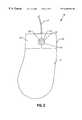
- a computer pointing device or joystick integrated mouse (JIM) 10is shown in a perspective view in FIG. 1 and a top view in FIG. 2 .
- the JIM 10includes a housing 11 , a joystick or lever 12 (which may be elongated as shown), buttons 14 and 16 , and a mouse cord, line, or cable 17 .
- the housingmechanically supports the buttons 14 (“left mouse button”) and 16 (“right mouse button”), as well as the lever 12 .
- the lever 12is mechanically coupled to the housing 11 at a pivot end 13 .
- the pivot end 13allows the lever 12 to be pivoted by a thumb or finger(s) touching an extended end 15 , or along its shaft 19 .
- the lever 12may be positioned and supported by the housing 11 between the mouse buttons 14 and 16 .
- the pivot end 13may have any suitable structure and mechanism known in the art.
- the pivot end 13may be a ball in a ball and socket arrangement, with the socket formed in the housing 11 .
- the housing 11encases electronic circuitry (not shown) for generating output signals responsive to the operation of the button 14 , the button 16 , and the lever 12 .
- electronic circuitry(not shown) for generating output signals responsive to the operation of the button 14 , the button 16 , and the lever 12 .
- the design and implementation of such circuitryis well known in the art, although some modification may be desirable to facilitate including joystick and mouse functionality in the same device.
- the housing for a conventional mouseis principally designed to fit the contours of the user's hand rather than to house the electronic circuitry.
- the housing for a conventional mouseis therefore largely empty since the electronic circuitry for a conventional mouse is relatively compact.
- the housing 11can therefore be implemented with conventional designs modified to accommodate the lever 12 and accompanying electronic circuitry.
- the internal wiring for mouse and joystick functionality in the JIM 10which transmits signals via the cord 17 to the computer (not shown), may be identical to that used for a conventional mouse and a stand-alone joystick, with one notable exception.
- the exceptionis that the wiring which carries signals in response to positioning the pointer/object/cursor on-screen with the lever 12 is coupled together within the JIM 10 to the wiring which carries signals in response to rotating the ball (discussed below) to position the pointer/object/cursor on-screen.
- the JIM 10includes features and functionality of both a computer mouse and a stand-alone joystick.
- the cord 17may terminate in a terminal connector, for example, a standard 9-pin D connector 17 a or a standard PS/2 connector 17 b to couple to a corresponding I/O port of a PC or workstation (not shown).
- the cord 17may also terminate in other types of connectors as would be appropriate for a particular computer system implementation.
- the JIM 10may also incorporate qualities of both the ball design and the touchpad.
- the JIM 10may be ergonomic, require little maneuvering space, and position and/or select screen pointers/objects/cursors very precisely in computer monitor on-screen displays provided by software applications running on the computer.
- the JIM 10allows a user to precisely move the screen pointer without losing any of the functionality of a typical mouse.
- the lever 12may be used to play games much as an ordinary stand-alone joystick, thus allowing the user to enjoy the benefits of the ordinary joystick without having to spend extra money on a separate device, tie up a game or other port, or require a separate controller or separate driver.
- buttons 14 and 16have the same functionality as conventional mouse buttons which, when depressed, cause corresponding conventional left- and right-hand mouse button pointing and/or selection signals to be issued from the JIM 10 and transmitted via the cord 17 to the computer system to which it is coupled. These signals include signals for normal select and normal drag functions which are generated by depressing the button 14 , and context menu and special drag functions which are generated by depressing the button 16 . For example, buttons 14 and 16 may be used to send signals to the computer system to “click” or “double click” on objects or items, or to “drag and drop” objects or items, on-screen, much as a conventional mouse.
- the “right-handed” JIM 10 shown in FIGS. 1 and 2is designed to be used by right-handed users. It is understood, however, that an equivalent “left-handed” JIM 10 for left-handed users, having the same features, but with the positions of buttons 14 and 16 reversed and contoured for left-handed manipulation, is included in the instant invention.
- the left-handed implementationis simply not shown for purposes of limiting redundancy in the drawings.
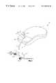
- a JIM 10 ′is shown in a perspective view in FIG. 4 in accordance with a second embodiment of the invention.
- the JIM 10 ′has all the features and functionality of the JIM 10 in FIGS. 1-3, but includes additionally a mouse button 18 which operates similar to, and has the same functionality as, the mouse button 14 (the “left-hand” mouse button).
- the mouse button 18is located on the right-hand thumb side 21 a of the device 10 ′, and is mechanically supported on the side 21 a by the housing 21 (the housing 21 is functionally analogous to the housing 11 of the JIM 10 ).
- a usermay depress the button 18 instead of the button 14 to send the same or similar left button output signals to the computer (not shown) via cable 17 .
- the JIM 10 ′has similar structural and connectivity features as the JIM 10 in FIGS. 1-3. As with the JIM 10 , although the JIM 10 ′ is depicted in the drawings as being “right-handed”, it is understood that an equivalent “left-handed” JIM 10 ′ is included in the instant invention with the positions of buttons 14 and 16 reversed.
- the user's “mouse” handi.e., the hand manipulating the JIMs 10 or 10 ′
- the user's “mouse” handmay be positioned such that the lever 12 is located comfortably between the index and second fingers of the same hand.
- the joystick functionality of the JIMs 10 or 10 ′the user may simply place one finger (e.g., the index finger) on the lever 12 to position it, or hold the JIMs 10 or 10 ′ with one hand and position the lever 12 with the index (or other) finger, or fingers, of the other hand.
- Such exemplary types of manipulation of the lever 12may occur, for example, while the user is playing a computer game.
- the button 18 of the JIM 10 ′may be disposed on the (left) side 21 a (or corresponding right side for a “left-handed” JIM 10 ′) to facilitate accessibility with the user's thumb.
- the usercould use the index finger of the same hand to move (pivot) the lever 12 to control the position of a pointer/object/cursor on-screen.
- the button 18may be depressed with the thumb to activate left-hand mouse button functionality while the index finger manipulates the lever 12 .
- the lever 12may be moved at its extended end 15 or anywhere along the length of its shaft 19 .
- buttons 14 , 16 , or 18the user may wish to use any combination of fingers or thumbs of either hand to depress buttons 14 , 16 , or 18 , and/or to move the lever 12 to position or make selections with the pointer/object/cursor onscreen while running software applications. Depressing the buttons 14 and 16 passes signals to the software application running on the computer. Depending on the number of times the buttons are depressed (“clicked”) and the position of the pointer/object/cursor at the time of the clicks, the software application performs the task the user wants to accomplish.
- These software programsmay or may not include a game having joystick input-control capability.
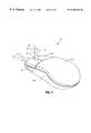
- FIGS. 5 a - 5 b and 6illustrate a third embodiment of the invention, JIM 10 ′′, employing retractable feet 20 .
- the JIM 10 ′′includes all of the features and functionality of the JIM 10 .
- FIGS. 5 a - 5 balthough this particular embodiment does not include the side mouse button 18 as in the second embodiment (JIM 10 ′) described above, the side mouse button 18 could be included along with its associated signal-generating and transmitting electronic circuitry (not shown).
- FIG. 5 ashows the feet 20 in their extended position
- FIG. 5 bshows the feet 20 in their retracted position above a surface or desk 24 .
- a view of an underside 31 b of a housing 31 of the JIM 10 ′′reveals the extendible/retractable “feet” 20 in their extended position (the housing 31 is functionally analogous to the housing 11 of the JIM 10 ).
- the feet 20can be extended to disengage a ball 22 a of a trackball unit 22 (shown best in FIG. 6) from the surface 24 to prevent rotation of the ball 22 a and to provide stability while pivoting the lever 12 .
- Extending the feet 20disengages the trackball unit 22 from the surface 24 by raising the trackball unit 22 above the surface 24 .
- FIG. 5 aAs shown in FIG.
- the feet 20when retracted, allow the JIM 10 ′′ to be positioned to operate the trackball unit 22 to rotate the ball 22 a on surface 24 when the JIM 10 ′′ is to be used as a conventional mouse device to move a pointer/object/cursor on-screen.
- each of the feet 20could include opposed tabs or a rotatable shaft mounted in the housing 31 near the underside 31 b which may be aligned along an axis (not shown) parallel to the surface 24 when the JIM 10 ′′ is placed on the surface 24 .
- the usermay simply “flip” each of the feet 20 down to lock in the extended position by rotating or pivoting each of the feet 20 about the axis (i.e., by rotating the opposed tabs or rotatable shaft about the axis with a force on the feet 20 such that each of the feet 20 move down and away from the underside 31 b until fully extended).
- the userWhen the feet 20 are to be retracted, the user then “flips” or pivots each of the feet 20 back up from the locked position which rotates the opposed tabs or rotatable shaft about the axis in the opposite direction from that described above (i.e., the feet 20 are pushed toward the underside 31 b until fully retracted).
- This implementationis merely exemplary and other structures and mechanisms could instead be used.
- the JIM 10 ′′With the feet 20 retracted, the JIM 10 ′′ can be moved about the surface 24 and the rotation of the ball 22 a in the trackball unit 22 will be converted to an electrical output signal carried by the cord 17 to the computer (not shown).
- the conversionin general, involves the turning of two rollers (not shown) which touch the trackball 22 a and which are mounted at a 90 degree angle to each other, as is known in the art. Each of these rollers is attached to a wheel or encoder (not shown). As the ball 22 a rotates, it imparts the turning motion on the rollers, which turns the encoders. The encoders produce intermittent electrical signals as they turn.
- the direction in which the rollers turn and the ratio between the number of signals from the rollersis an indication of the direction in which the mouse is moved.
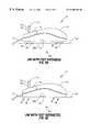
- FIG. 7 aschematically shows the directions from a top view perspective in which the JIM 10 ′′ may be moved by a user on the surface 24 with the feet 20 (not shown in FIG. 7a) retracted. Like a conventional mouse, the JIM 10 ′′ may be moved linearly or in two dimensions (for mouse operation) with 360° of motion possible on the surface 24 .
- FIG. 7 ashows the directions of possible motion for the JIM 10 ′′, it is to be understood that either of the first or second embodiments (i.e., the JIMs 10 and 10 ′) will have the same capability (except there are no feet 20 ).
- the trackball 22 a of the trackball unit 22does not touch the surface 24 , thus rendering it inoperative.
- Thisallows the lever 12 to be used to move the pointer/object/cursor on-screen without interference from, or competing with, the trackball 22 a .
- Thisis in contrast to when the feet 20 are retracted, where the lever 12 could also be used to move the pointer/object/cursor on-screen in addition to being movable by rotation of the ball 22 a .
- Extending the feet 20also allows the pointer/object/cursor to be moved on-screen with the lever 12 without excessive surface 24 real estate being needed.
- FIG. 7 bschematically shows the directions (also similar for JIMs 10 and 10 ′) in which the lever 12 may be moved by the user.
- the feet 20are in their extended position (only two of the typically four feet 20 are visible in FIG. 7 b , although three or another number are also possible). It is not necessary that the feet 20 be extended, although, if they are extended, the likelihood of the JIM 10 ′′ slipping on the surface 24 when the lever 12 is manipulated is reduced compared to when the feet 20 are retracted.
- the lever 12may be pivoted linearly or pivoted in two dimensions about its pivot end 13 to move the pointer/object/cursor on-screen.
- the lever 12will continue to produce the output signal carried by cable 17 to the computer to move the pointer/object/cursor as long as the lever 12 is pivoted out of its nominally centered position (i.e., its neutral or vertical position) if the lever 12 acts as a pointer/object/cursor relative on-screen position joystick (i.e., as a relative position joystick).
- the lever 12could be designed to act as an absolute position joystick in which the position of the lever 12 corresponds to an absolute position onscreen.
- a JIM 10 ′′′is shown in a perspective view.
- the JIM 10 ′′′includes a joystick 42 which is positioned on a side 41 a of a housing 41 and supported by the housing 41 .
- the housing 41is functionally analogous to the housing 11 of the JIM 10 .
- the joystick 42is coupled at a pivot end 43 to the housing 41 and has an extended end 45 distal from the pivot end 43 along a shaft 49 , the lever 42 and both ends 43 and 45 being functionally analogous to the lever 12 and ends 13 and 15 , respectively, of the JIM 10 (or 10 ′ or 10 ′′).
- the joystick 42has all the pointer/object/cursor pointing and moving functionality of the joystick 12 of the JIM 10 (or 10 ′ or 10 ′′).
- the joystick 42has circuitry similar to that of the joystick 12 which is used to output signals controlling the pointer/object/cursor position, as carried by the cable 17 , to the computer system (not shown).
- a left-hand mouse button 44 and a right-hand mouse button 46are included in the JIM 10 ′′′ which are analogous to, and have similar functionality as, the left-hand mouse button 14 and the right-hand mouse button 16 , respectively, of the JIM 10 (or 10 ′ or 10 ′′).
- the JIM 10 ′′′may also include extendible/retractable feet 20 like the JIM 10 ′′. Only two of the typically four feet 20 are visible in their extended position in FIG. 8, although three, none, or another number are also possible.
- a user's handwould be placed on the JIM 10 ′′′ such that his or her thumb could manipulate the joystick 42 (although a finger could also be used).
- the lefthand and right-hand mouse button functionalitywould be accessible to the user by depressing the buttons 44 and 46 with the index and second fingers, respectively, or with thumbs, or even other fingers.
- the useralso may manipulate the joystick 42 with or without depressing the buttons 44 and 46 with any finger or thumb as he or she pleases.
- the JIMs 10 , 10 ′, 10 ′′ and 10 ′′′may be used as a mouse device, as a joystick device, or as a combination of both, for on-screen control of the pointer/object/cursor in a graphic interface provided in software applications running on the computer system, where the pointer/object/cursor is mouse controllable.
- FIG. 9a flowchart of a method (a “mouse” method), in accordance with an embodiment of the invention, is shown.
- the “mouse” methodprovides for the user to place/maintain as in block 102 his or her hand on the pointing device 10 , 10 ′, or 10 ′′ with the lever 12 between the user's index finger and second finger.
- the usermoves as in block 104 the pointing device 10 , 10 ′ or 10 ′′ around as a mouse when the screen pointer/object/cursor is to be moved.
- the userdepresses as in block 106 the left-hand mouse button 14 or 18 when the left-hand mouse button functionality is to be activated, and the user depresses as in block 108 the right-hand mouse button 16 with the second finger when the right-hand button functionality is to be activated.
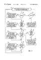
- FIG. 10Another flowchart of a method (a “joystick” method), in accordance with an embodiment of the invention, is shown in FIG. 10 .
- the “joystick” methodprovides for the user to place/maintain as in block 120 his or her hand on the pointing device 10 , 10 ′ or 10 ′′ with his or her index or other finger on the lever 12 .
- the usermoves as in block 122 the lever 12 with his or her index or other finger when a game is to be played or when the screen pointer/object/cursor is to be moved.
- the processmay repeat by going back to block 120 .
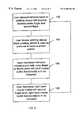
- FIG. 11An additional flowchart of a method (a “mouse/joystick” method), in accordance with an embodiment of the invention, is illustrated in FIG. 11 .
- the usermakes as in block 140 a decision to use either mouse or joystick functionality of the pointing device 10 , 10 ′ or 10 ′′. If the user chooses as in block 142 mouse functionality, the user may place/maintain as in block 144 his or her hand on the pointing device 10 , 10 ′ or 10 ′′ with the lever 12 between his or her fingers.
- the usermay move as in block 148 the pointing device 10 , 10 ′ or 10 ′′ around as a mouse to produce a corresponding signal carried by the cord 17 to the computer to move or select the screen pointer/object/cursor. If the screen pointer/object/cursor is not to be moved, or once it has been moved, it is determined if the left-hand mouse button is to be activated as in block 150 .
- the usermay depress as in block 152 the left-hand mouse button 14 or 18 to activate lefthand mouse button functionality. If, on the other hand, the left-hand mouse button is not to be activated, or if it already has been activated, it is determined if the right-hand mouse button is to be activated (i.e., by depressing it) as in block 154 . If the right-hand mouse button is to be activated, the user may depress as in block 156 the right-hand mouse button 16 with his or her second or other finger to activate right-hand mouse button functionality.
- the processreturns to block 140 for the user to make a decision whether to invoke mouse or joystick functionality of the pointing device 10 , 10 ′, or 10 ′′.
- the usermay place/maintain as in block 160 his or her hand on the pointing device 10 , 10 ′, or 10 ′′ with his or her index or other finger on the lever 12 . If the user decided not to use the lever 12 , then the process proceeds back to block 140 . If, however, it is determined that the screen pointer/object/cursor is to be moved as in block 162 with the lever 12 , the user may move as in block 164 the lever 12 with his or her index or other finger or thumb to move the screen pointer/object/cursor, or to play a game.
- the processproceeds to determine if the left-hand mouse button 14 or 18 is to be activated as in block 150 . The process then proceeds as described above.
Landscapes
- Engineering & Computer Science (AREA)
- General Engineering & Computer Science (AREA)
- Theoretical Computer Science (AREA)
- Human Computer Interaction (AREA)
- Physics & Mathematics (AREA)
- General Physics & Mathematics (AREA)
- Position Input By Displaying (AREA)
Abstract
Description
1. Field of the Invention
The invention relates in general to inputting data using computer input/output (I/O) devices and, more particularly, to a pointing device.
2. Description of Related Art
A typical computer system (e.g., a personal computer or PC, or a workstation) includes input/output (I/O) devices, for example, a mechanical mouse, a trackball, a touchpad, a digitizing tablet, a stand-alone joystick, a touchscreen, or a light pen as a pointing or selection device. These devices may be used to send signals to the computer system to move a pointer (e.g., a cursor or arrow) displayed on a monitor screen of the system in a graphic or other interface of a software application running on the system. The devices send signals to the system to make a selection from amongst items or objects displayed in the application on the monitor. I/O devices may be serial or parallel and coupled to the computer through corresponding serial or parallel computer ports.
Many of these I/O devices have been ergonomically designed and produced, and include, for example, movable balls held underneath the device or a touchpad. When a user moves the device around on, for example, a mousepad, the ball rotates, and the motion of the ball is converted into a signal which is input to the computer to move the pointer about the screen of the computer. Using the ball design requires the user to have a fairly large open space (“real estate”) on a surface, table, or desk on which to maneuver the device. If surface real estate is limited, such designs inefficiently use desktop space. The ball design also has exposed moving parts (e.g., the ball and its rotation sensors) that may become dirty or pick up lint/particles from the mousepad or desktop. Dirt may diminish the response and usefulness of such a device.
The touchpad eliminates the problem of lint/particles because it has no exposed moving parts, and it efficiently uses space. The touchpad, however, may not allow the sufficiently precise pointer positioning necessary for many programs, such as computeraided design (“CAD”) programs. This is because of imprecision associated with sliding a finger on the touchpad as a means to move the pointer. The touchpad may also not appeal to the ergonomically aware and may not be the best tool for playing mouseenabled games.
The stand-alone joystick, which may be used with, for example, computer games, is coupled to an input serial port (e.g., a gameport) of the computer. A computer system having both a mouse and a stand-alone joystick would therefore require tying-up two of the system's ports. Moreover, the stand-alone joystick requires the computer to be programmed with a separate controller than a mouse controller, and a separate driver than a mouse driver.
In view of the above, there is a need for an I/O pointing device that provides multiple features and precise pointer positioning, does not require an inordinate amount of desktop real estate, does not unnecessarily tie up additional computer I/O ports, does not require a separate controller, and does not require a separate driver.
The invention, in one embodiment, is a computer pointing device that includes: (1) a housing; (2) a first depressible button supported by the housing which, when pressed, causes a first signal to be generated; (3) a second depressible button supported by the housing which, when pressed, causes a second signal to be generated; (4) a cable coupled to transmit the first signal and the second signal; and (5) a lever pivotably coupled to the housing at one end.
FIG. 1 shows a perspective view of a computer pointing device in accordance with a first embodiment of the invention.
FIG. 2 shows a top view of the device in FIG.1.
FIG. 3 shows connectors for the device in FIG.1.
FIG. 4 shows a perspective view of another computer pointing device in accordance with a second embodiment of the invention.
FIGS. 5a-5bshow side views of another computer pointing device in accordance with a third embodiment of the invention.
FIG. 6 shows a bottom view of the device in FIGS. 5a-5b.
FIG. 7aillustrates the possible range of motion of the computer pointing device in FIGS. 5a-5band6 on a surface.
FIG. 7bshows a representation of possible directions of pivotal motion of a portion of the computer pointing device in FIGS. 5a-5band6.
FIG. 8 shows a perspective view of another computer pointing device in accordance with a fourth embodiment of the invention.
FIG. 9 is a flowchart of a method in accordance with an embodiment of the invention.
FIG. 10 is a flowchart of another method in accordance with an embodiment of the invention.
FIG. 11 is a flowchart of another method in accordance with an embodiment of the invention.
While the invention is susceptible to various modifications and alternative forms, specific embodiments thereof have been shown by way of example in the drawings and are herein described in detail. It should be understood, however, that the description herein of specific embodiments is not intended to limit the invention to the particular forms disclosed, but on the contrary, the intention is to cover all modifications, equivalents, and alternatives falling within the spirit and scope of the invention as defined by the appended claims.
Illustrative embodiments of the invention are described below. In the interest of clarity, not all features of an actual implementation are described in this specification. It will of course be appreciated that in the development of any such actual embodiment, numerous implementation-specific decisions must be made to achieve the developers'specific goals, such as compliance with system-related and business-related constraints, which will vary from one implementation to another. Moreover, it will be appreciated that, even if such a development effort might be complex and time-consuming, it would nevertheless be a routine undertaking for those of ordinary skill in the art having the benefit of this disclosure.
A First Embodiment of the Invention
In accordance with a first embodiment of the invention, a computer pointing device or joystick integrated mouse (JIM)10 is shown in a perspective view in FIG. 1 and a top view in FIG.2. The JIM10 includes ahousing 11, a joystick or lever12 (which may be elongated as shown),buttons cable 17. The housing mechanically supports the buttons14 (“left mouse button”) and16 (“right mouse button”), as well as thelever 12. Thelever 12 is mechanically coupled to thehousing 11 at apivot end 13. Thepivot end 13 allows thelever 12 to be pivoted by a thumb or finger(s) touching an extendedend 15, or along itsshaft 19. Thelever 12 may be positioned and supported by thehousing 11 between themouse buttons pivot end 13 may have any suitable structure and mechanism known in the art. For example, thepivot end 13 may be a ball in a ball and socket arrangement, with the socket formed in thehousing 11.
Thehousing 11 encases electronic circuitry (not shown) for generating output signals responsive to the operation of thebutton 14, thebutton 16, and thelever 12. The design and implementation of such circuitry is well known in the art, although some modification may be desirable to facilitate including joystick and mouse functionality in the same device. Furthermore, the housing for a conventional mouse is principally designed to fit the contours of the user's hand rather than to house the electronic circuitry. The housing for a conventional mouse is therefore largely empty since the electronic circuitry for a conventional mouse is relatively compact. Thehousing 11 can therefore be implemented with conventional designs modified to accommodate thelever 12 and accompanying electronic circuitry.
The internal wiring for mouse and joystick functionality in theJIM 10, which transmits signals via thecord 17 to the computer (not shown), may be identical to that used for a conventional mouse and a stand-alone joystick, with one notable exception. The exception is that the wiring which carries signals in response to positioning the pointer/object/cursor on-screen with thelever 12 is coupled together within theJIM 10 to the wiring which carries signals in response to rotating the ball (discussed below) to position the pointer/object/cursor on-screen. From the point where the wiring is coupled to the computer (including the cord17), there is no separate wiring to carry signals in response to moving thelever 12, or in response to moving theJIM 10 on a surface (e.g., on a mousepad) to rotate the ball (discussed below). No additional computer port is tied up when coupling thecable 17 to use thelever 12.
TheJIM 10 includes features and functionality of both a computer mouse and a stand-alone joystick. For example, as shown in FIG. 3, thecord 17 may terminate in a terminal connector, for example, a standard 9-pin D connector 17aor a standard PS/2connector 17bto couple to a corresponding I/O port of a PC or workstation (not shown). Thecord 17 may also terminate in other types of connectors as would be appropriate for a particular computer system implementation.
TheJIM 10 may also incorporate qualities of both the ball design and the touchpad. For example, theJIM 10 may be ergonomic, require little maneuvering space, and position and/or select screen pointers/objects/cursors very precisely in computer monitor on-screen displays provided by software applications running on the computer. TheJIM 10 allows a user to precisely move the screen pointer without losing any of the functionality of a typical mouse. Thelever 12 may be used to play games much as an ordinary stand-alone joystick, thus allowing the user to enjoy the benefits of the ordinary joystick without having to spend extra money on a separate device, tie up a game or other port, or require a separate controller or separate driver.
Thebuttons JIM 10 and transmitted via thecord 17 to the computer system to which it is coupled. These signals include signals for normal select and normal drag functions which are generated by depressing thebutton 14, and context menu and special drag functions which are generated by depressing thebutton 16. For example,buttons
The “right-handed”JIM 10 shown in FIGS. 1 and 2 is designed to be used by right-handed users. It is understood, however, that an equivalent “left-handed”JIM 10 for left-handed users, having the same features, but with the positions ofbuttons
A Second Embodiment of the Invention
AJIM 10′ is shown in a perspective view in FIG. 4 in accordance with a second embodiment of the invention. TheJIM 10′ has all the features and functionality of theJIM 10 in FIGS. 1-3, but includes additionally amouse button 18 which operates similar to, and has the same functionality as, the mouse button14 (the “left-hand” mouse button). In FIG. 4, themouse button 18 is located on the right-hand thumb side 21aof thedevice 10′, and is mechanically supported on theside 21aby the housing21 (thehousing 21 is functionally analogous to thehousing 11 of the JIM10). A user may depress thebutton 18 instead of thebutton 14 to send the same or similar left button output signals to the computer (not shown) viacable 17.
Other than theadditional button 18 and its coupling to the same circuitry (not shown) that generates these signals in theJIM 10′, theJIM 10′ has similar structural and connectivity features as theJIM 10 in FIGS. 1-3. As with theJIM 10, although theJIM 10′ is depicted in the drawings as being “right-handed”, it is understood that an equivalent “left-handed”JIM 10′ is included in the instant invention with the positions ofbuttons
When the mouse functionality of theJIMs JIMs lever 12 is located comfortably between the index and second fingers of the same hand. When the joystick functionality of theJIMs lever 12 to position it, or hold theJIMs lever 12 with the index (or other) finger, or fingers, of the other hand. Such exemplary types of manipulation of thelever 12 may occur, for example, while the user is playing a computer game.
Thebutton 18 of theJIM 10′ may be disposed on the (left)side 21a(or corresponding right side for a “left-handed”JIM 10′) to facilitate accessibility with the user's thumb. The user could use the index finger of the same hand to move (pivot) thelever 12 to control the position of a pointer/object/cursor on-screen. Thebutton 18 may be depressed with the thumb to activate left-hand mouse button functionality while the index finger manipulates thelever 12. Thelever 12 may be moved at itsextended end 15 or anywhere along the length of itsshaft 19. Alternatively, the user may wish to use any combination of fingers or thumbs of either hand to depressbuttons lever 12 to position or make selections with the pointer/object/cursor onscreen while running software applications. Depressing thebuttons
A Third Embodiment of the Invention
FIGS. 5a-5band6 illustrate a third embodiment of the invention,JIM 10″, employingretractable feet 20. Other than thefeet 20, theJIM 10″ includes all of the features and functionality of theJIM 10. As shown in FIGS. 5a-5b, although this particular embodiment does not include theside mouse button 18 as in the second embodiment (JIM 10′) described above, theside mouse button 18 could be included along with its associated signal-generating and transmitting electronic circuitry (not shown). FIG. 5ashows thefeet 20 in their extended position and FIG. 5bshows thefeet 20 in their retracted position above a surface ordesk 24.
Referring to FIG. 6, a view of anunderside 31bof ahousing 31 of theJIM 10″ reveals the extendible/retractable “feet”20 in their extended position (thehousing 31 is functionally analogous to thehousing 11 of the JIM10). As shown in the side view in FIG. 5a, thefeet 20 can be extended to disengage aball 22aof a trackball unit22 (shown best in FIG. 6) from thesurface 24 to prevent rotation of theball 22aand to provide stability while pivoting thelever 12. Extending thefeet 20, as shown in FIG. 5a, disengages thetrackball unit 22 from thesurface 24 by raising thetrackball unit 22 above thesurface 24. As shown in FIG. 5bfor theJIM 10″, thefeet 20, when retracted, allow theJIM 10″ to be positioned to operate thetrackball unit 22 to rotate theball 22aonsurface 24 when theJIM 10″ is to be used as a conventional mouse device to move a pointer/object/cursor on-screen.
The structure and mechanism of thefeet 20 may be of any suitable implementation known in the art. For example, each of thefeet 20 could include opposed tabs or a rotatable shaft mounted in thehousing 31 near theunderside 31bwhich may be aligned along an axis (not shown) parallel to thesurface 24 when theJIM 10″ is placed on thesurface 24. The user may simply “flip” each of thefeet 20 down to lock in the extended position by rotating or pivoting each of thefeet 20 about the axis (i.e., by rotating the opposed tabs or rotatable shaft about the axis with a force on thefeet 20 such that each of thefeet 20 move down and away from theunderside 31buntil fully extended). When thefeet 20 are to be retracted, the user then “flips” or pivots each of thefeet 20 back up from the locked position which rotates the opposed tabs or rotatable shaft about the axis in the opposite direction from that described above (i.e., thefeet 20 are pushed toward theunderside 31buntil fully retracted). This implementation is merely exemplary and other structures and mechanisms could instead be used.
With thefeet 20 retracted, theJIM 10″ can be moved about thesurface 24 and the rotation of theball 22ain thetrackball unit 22 will be converted to an electrical output signal carried by thecord 17 to the computer (not shown). The conversion, in general, involves the turning of two rollers (not shown) which touch thetrackball 22aand which are mounted at a 90 degree angle to each other, as is known in the art. Each of these rollers is attached to a wheel or encoder (not shown). As theball 22arotates, it imparts the turning motion on the rollers, which turns the encoders. The encoders produce intermittent electrical signals as they turn. The more theball 22ais rotated, the more of these signals are produced, and the number of signals is indicative of how far theball 22ahas been rotated (which corresponds to how far theJIM 10″[or10 or10′] have been moved, for example, on the surface24). The direction in which the rollers turn and the ratio between the number of signals from the rollers is an indication of the direction in which the mouse is moved.
Signals corresponding to the number of intermittent signals produced by the encoders, to the ratio, and to the frequency of signals from the two encoders, are sent via thecord 17 to the software application running on the computer to be converted to distance, direction, and speed required to move the on-screen pointer/object/cursor (i.e., for normal mouse operation). FIG. 7aschematically shows the directions from a top view perspective in which theJIM 10″ may be moved by a user on thesurface 24 with the feet20 (not shown in FIG. 7a) retracted. Like a conventional mouse, theJIM 10″ may be moved linearly or in two dimensions (for mouse operation) with 360° of motion possible on thesurface 24. Although FIG. 7ashows the directions of possible motion for theJIM 10″, it is to be understood that either of the first or second embodiments (i.e., theJIMs
On the other hand, for theJIM 10″, with thefeet 20 extended, thetrackball 22aof thetrackball unit 22 does not touch thesurface 24, thus rendering it inoperative. This allows thelever 12 to be used to move the pointer/object/cursor on-screen without interference from, or competing with, thetrackball 22a. This is in contrast to when thefeet 20 are retracted, where thelever 12 could also be used to move the pointer/object/cursor on-screen in addition to being movable by rotation of theball 22a. Extending thefeet 20 also allows the pointer/object/cursor to be moved on-screen with thelever 12 withoutexcessive surface 24 real estate being needed.
FIG. 7bschematically shows the directions (also similar forJIMs lever 12 may be moved by the user. In FIG. 7b, thefeet 20 are in their extended position (only two of the typically fourfeet 20 are visible in FIG. 7b, although three or another number are also possible). It is not necessary that thefeet 20 be extended, although, if they are extended, the likelihood of theJIM 10″ slipping on thesurface 24 when thelever 12 is manipulated is reduced compared to when thefeet 20 are retracted. Like a conventional stand-alone joystick, thelever 12 may be pivoted linearly or pivoted in two dimensions about itspivot end 13 to move the pointer/object/cursor on-screen. Close to a half-sphere of motion of thelever 12 may be possible about thepivot end 13. Moving thelever 12 forward along the direction ofarrow 30bin FIG. 7bproduces the same output signal carried bycable 17 to the computer as when rolling the mouse forward along the direction ofarrow 30ain FIG. 7a(i.e., in the same or a corresponding direction). The same is true for all other corresponding directions on thesurface 24. Similar motion is also possible for thelever 12 of theJIMs
Thelever 12 will continue to produce the output signal carried bycable 17 to the computer to move the pointer/object/cursor as long as thelever 12 is pivoted out of its nominally centered position (i.e., its neutral or vertical position) if thelever 12 acts as a pointer/object/cursor relative on-screen position joystick (i.e., as a relative position joystick). Alternatively, thelever 12 could be designed to act as an absolute position joystick in which the position of thelever 12 corresponds to an absolute position onscreen. This is in contrast to when theJIM 10″(or10 or10′) operates as a normal mouse in which a corresponding output signal will only continue to be produced if theball 22ais rotated (i.e., when the user pushes theJIM 10″[or10 or10′] on the surface24), because the encoder signals continue to be produced, as discussed.
A Fourth Embodiment of the Invention
Referring to FIG. 8, in accordance with a fourth embodiment of the invention, aJIM 10′″ is shown in a perspective view. TheJIM 10′″ includes ajoystick 42 which is positioned on aside 41aof ahousing 41 and supported by thehousing 41. Thehousing 41 is functionally analogous to thehousing 11 of theJIM 10.
Thejoystick 42 is coupled at a pivot end43 to thehousing 41 and has anextended end 45 distal from the pivot end43 along ashaft 49, thelever 42 and both ends43 and45 being functionally analogous to thelever 12 and ends13 and15, respectively, of the JIM10 (or10′ or10″). Thejoystick 42 has all the pointer/object/cursor pointing and moving functionality of thejoystick 12 of the JIM10 (or10′ or10″). Thejoystick 42 has circuitry similar to that of thejoystick 12 which is used to output signals controlling the pointer/object/cursor position, as carried by thecable 17, to the computer system (not shown).
A left-hand mouse button 44 and a right-hand mouse button 46 are included in theJIM 10′″ which are analogous to, and have similar functionality as, the left-hand mouse button 14 and the right-hand mouse button 16, respectively, of the JIM10 (or10′ or10″). TheJIM 10′″ may also include extendible/retractable feet 20 like theJIM 10″. Only two of the typically fourfeet 20 are visible in their extended position in FIG. 8, although three, none, or another number are also possible.
In typical use, a user's hand would be placed on theJIM 10′″ such that his or her thumb could manipulate the joystick42 (although a finger could also be used). The lefthand and right-hand mouse button functionality would be accessible to the user by depressing thebuttons joystick 42 with or without depressing thebuttons
Method of Entering Data Using the JIM as a Pointing Device
The remaining discussion focuses on methods of entering data into a computer using theJIMs JIMs
Referring to FIG. 9, a flowchart of a method (a “mouse” method), in accordance with an embodiment of the invention, is shown. The “mouse” method provides for the user to place/maintain as inblock 102 his or her hand on thepointing device lever 12 between the user's index finger and second finger. The user moves as inblock 104 thepointing device block 106 the left-hand mouse button block 108 the right-hand mouse button 16 with the second finger when the right-hand button functionality is to be activated.
Another flowchart of a method (a “joystick” method), in accordance with an embodiment of the invention, is shown in FIG.10. The “joystick” method provides for the user to place/maintain as inblock 120 his or her hand on thepointing device lever 12. The user moves as inblock 122 thelever 12 with his or her index or other finger when a game is to be played or when the screen pointer/object/cursor is to be moved. The user presses as inblock 124 thelefthand mouse button block 126 the right-hand mouse button 16 with his or her second or other finger when the right-hand mouse button functionality is to be activated. The process may repeat by going back to block120.
An additional flowchart of a method (a “mouse/joystick” method), in accordance with an embodiment of the invention, is illustrated in FIG.11. In the “mouse/joystick” method, the user makes as in block140 a decision to use either mouse or joystick functionality of thepointing device block 142 mouse functionality, the user may place/maintain as inblock 144 his or her hand on thepointing device lever 12 between his or her fingers. If the screen pointer/object/cursor is to be moved as inblock 146, the user may move as inblock 148 thepointing device cord 17 to the computer to move or select the screen pointer/object/cursor. If the screen pointer/object/cursor is not to be moved, or once it has been moved, it is determined if the left-hand mouse button is to be activated as inblock 150.
If the left-hand mouse button block 152 the left-hand mouse button block 154. If the right-hand mouse button is to be activated, the user may depress as inblock 156 the right-hand mouse button 16 with his or her second or other finger to activate right-hand mouse button functionality. If, however, the right-hand mouse button is not to be activated, or once it has been activated, the process returns to block140 for the user to make a decision whether to invoke mouse or joystick functionality of thepointing device
At this point, if the user decides not to use the mouse, or if the user decided previously not to use the mouse, and, instead, decided to use thelever 12 as inblock 158, the user may place/maintain as inblock 160 his or her hand on thepointing device lever 12. If the user decided not to use thelever 12, then the process proceeds back to block140. If, however, it is determined that the screen pointer/object/cursor is to be moved as inblock 162 with thelever 12, the user may move as inblock 164 thelever 12 with his or her index or other finger or thumb to move the screen pointer/object/cursor, or to play a game. If, on the other hand, the screen pointer/object/cursor is not to be moved, or after it has been moved, the process proceeds to determine if the left-hand mouse button block 150. The process then proceeds as described above.
Remarks
The particular embodiments disclosed above are illustrative only, as the invention may be modified and practiced in different but equivalent manners apparent to those skilled in the art having the benefit of the teachings herein. Furthermore, no limitations are intended to the details of construction or design herein shown, other than as described in the claims below. It is therefore evident that the particular embodiments disclosed above may be altered or modified and all such variations are considered within the scope and spirit of the invention. Accordingly, the protection sought herein is as set forth in the claims below.
Claims (24)
1. A computer pointing device, comprising;
housing;
a mouse component enclosed within the housing, the mouse component adapted to generate a signal representing movement of the pointing device in a plane; and
a lever pivotably coupled to the housing at one end, the lever adapted to generate the signal when the lever is disturbed from a neutral position.
2. The computer pointing device ofclaim 1 , wherein the lever is adapted to be disturbed from the neutral position by a finger or thumb of a user.
3. The computer pointing device ofclaim 1 , wherein the lever comprises a joystick.
4. The computer pointing device ofclaim 1 , wherein the lever is disposed generally upward from the housing.
5. The computer pointing device ofclaim 1 , wherein the lever is disposed generally to the side of the housing.
6. The computer pointing device ofclaim 1 , further comprising:
an underside of the housing, said underside exposing a ball, the ball being one element of the mouse component, the ball adapted to roll in response to movement of the pointing device in the plane; and
feet extendible and retractable from the underside of the housing.
7. The computer pointing device ofclaim 6 , wherein the housing is raised from a surface when said feet are extended.
8. The computer pointing device ofclaim 1 , wherein the pointing device is contoured to fit a palm of a hand of a user.
9. The computer pointing device ofclaim 1 , wherein the lever is adapted to be pivotable 360 degrees from the neutral position.
10. The computer pointing device ofclaim 1 , further comprising a first depressible button supported by the housing, the first depressible button adapted to generate a first button signal when the first button is depressed.
11. The computer pointing device ofclaim 1 , further comprising a second depressible button supported by the housing, the second depressible button adapted to generate a second button signal when the second button is depressed.
12. The computer pointing device ofclaim 11 , further comprising a means for operatively coupling each of the signal, the first button signal and the second button signal to a computer system.
13. The computer pointing device ofclaim 12 , the means for operatively coupling is selected from the group consisting of a cable, an infrared interface and a radio frequency interface.
14. The computer pointing device ofclaim 11 , further comprising a third depressible button supported by the housing which, when depressed, causes the first button signal to be generated.
15. The computer pointing device ofclaim 14 , wherein the pointing device further comprises a cable for operatively coupling each of the signal, the first button signal and the second button signal to a computer system.
16. The computer pointing device ofclaim 1 , further comprising a means for operatively coupling the signal to a computer system.
17. The computer pointing device ofclaim 16 , wherein the means for operatively coupling is selected from the group consisting of a cable, an infrared interface and a radio frequency interface.
18. A computer pointing device comprising:
a mouse adapted to generate a motion signal representing movement of the pointing device in a plane, the mouse including:
a first depressible button which, when depressed, cause a first button signal to be generated,
a second depressible button which, when depressed, cause a second button signal to be generated;
a joystick operably mounted to the mouse which, when activated causes the motion signal to be generated; and
a cable adapted to operatively couple the motion signal, the first signal, and the second signal to another device.
19. The computer pointing device ofclaim 18 , further comprising a third depressible button supported by the mouse which, when depressed, causes the first button signal to be generated.
20. The computer pointing device ofclaim 18 , wherein the joystick is disposed generally upward from the mouse.
21. The computer pointing device ofclaim 18 , wherein the joystick2 is disposed generally to the side of the mouse.
22. The computer pointing device ofclaim 18 , wherein the mouse further includes a plurality of feet extendible and retractable from an underside thereof.
23. The computer pointing device ofclaim 22 , wherein the feet are adapted to raise the device from a surface when extended.
24. The computer pointing deviceclaim 18 , wherein the device is contoured to fit a palm of a hand of a user.
Priority Applications (1)
| Application Number | Priority Date | Filing Date | Title |
|---|---|---|---|
| US08/993,371US6480184B1 (en) | 1997-12-18 | 1997-12-18 | Apparatus for entering data into a computer |
Applications Claiming Priority (1)
| Application Number | Priority Date | Filing Date | Title |
|---|---|---|---|
| US08/993,371US6480184B1 (en) | 1997-12-18 | 1997-12-18 | Apparatus for entering data into a computer |
Publications (1)
| Publication Number | Publication Date |
|---|---|
| US6480184B1true US6480184B1 (en) | 2002-11-12 |
Family
ID=25539465
Family Applications (1)
| Application Number | Title | Priority Date | Filing Date |
|---|---|---|---|
| US08/993,371Expired - Fee RelatedUS6480184B1 (en) | 1997-12-18 | 1997-12-18 | Apparatus for entering data into a computer |
Country Status (1)
| Country | Link |
|---|---|
| US (1) | US6480184B1 (en) |
Cited By (27)
| Publication number | Priority date | Publication date | Assignee | Title |
|---|---|---|---|---|
| US20020167482A1 (en)* | 2001-05-14 | 2002-11-14 | Yin Memphis Zhihong | Portable computer system including detachable peripheral device and combined mouse/joystick for use with same |
| US20030214484A1 (en)* | 2002-05-20 | 2003-11-20 | Haywood Chad Christian | Convertible mouse |
| US20040041787A1 (en)* | 2002-08-28 | 2004-03-04 | Graves Robert A. | Method and apparatus for a hybrid pointing device used with a data processing system |
| US6714188B1 (en)* | 1999-06-11 | 2004-03-30 | An Ounce Of Invention, Inc | Stick to ergonomically manipulate mouse buttons |
| US6727889B2 (en)* | 2001-09-14 | 2004-04-27 | Stephen W. Shaw | Computer mouse input device with multi-axis palm control |
| DE10256659A1 (en)* | 2002-12-04 | 2004-07-08 | Siemens Ag | Input device for orientating a 3D medical image has means for selecting a reference point and means for fixing a viewing direction and setting a scale |
| US6822638B2 (en)* | 1999-05-10 | 2004-11-23 | International Business Machines Corporation | Pointing device for navigating a 3 dimensional GUI interface |
| US20050030279A1 (en)* | 2003-08-08 | 2005-02-10 | Liang Fu | Multi-functional pointing and control device |
| US20050190144A1 (en)* | 2004-02-26 | 2005-09-01 | Microsoft Corporation | Multi-modal navigation in a graphical user interface computing system |
| US6950092B2 (en)* | 2001-02-27 | 2005-09-27 | International Business Machines Corporation | Input device with multiple controls having interchangeable functionality |
| US20060077177A1 (en)* | 2004-10-08 | 2006-04-13 | Kirtley Donny K | Stationary ergonomic mouse |
| US20060290664A1 (en)* | 2005-06-22 | 2006-12-28 | Microsoft Corporation | Dual mode input device |
| US20070247426A1 (en)* | 2006-04-24 | 2007-10-25 | Vorst Adrian Van Der | Pointing device for navigating three dimensional space using multiple finger actuated sensors |
| US7407439B1 (en) | 2004-12-29 | 2008-08-05 | Ochoa Justin J | Apparatus and system for reconfigurable two-hand game controllers |
| US20080303792A1 (en)* | 2007-06-11 | 2008-12-11 | Kuei-Lin Chung | Mouse structure |
| US20090046064A1 (en)* | 2007-08-17 | 2009-02-19 | Microsoft Corporation | Pointing device for control of a graphical display or application |
| WO2008152056A3 (en)* | 2007-06-12 | 2009-07-16 | Dublin Inst Of Technology | Video game controller |
| US20100045602A1 (en)* | 2008-08-25 | 2010-02-25 | International Business Machines Corporation | Position input device with anchorage |
| US7768514B2 (en) | 2006-12-19 | 2010-08-03 | International Business Machines Corporation | Simultaneous view and point navigation |
| US20110001702A1 (en)* | 2009-07-03 | 2011-01-06 | Primax Electronics Ltd. | Mouse with changeable footpads |
| US20120061546A1 (en)* | 2010-09-10 | 2012-03-15 | Hamilton Lawrence E | Mouse Platform with Warning Track |
| US8576170B2 (en) | 2011-01-10 | 2013-11-05 | International Business Machines Corporation | Joystick type computer input device with mouse |
| US20180253156A1 (en)* | 2017-03-03 | 2018-09-06 | Primax Electronics Ltd. | Joystick-type mouse |
| US11537219B2 (en)* | 2018-08-07 | 2022-12-27 | The Research Foundation For The State University Of New York | Feedback input apparatus and method for use thereof |
| US20230195243A1 (en)* | 2021-12-20 | 2023-06-22 | Microsoft Technology Licensing, Llc | Directional input device for computer mouse |
| US20240082698A1 (en)* | 2022-09-09 | 2024-03-14 | Branden Duncan | Computer gaming device with docking features |
| US12111965B2 (en)* | 2022-06-14 | 2024-10-08 | Htc Corporation | Handheld controller |
Citations (19)
| Publication number | Priority date | Publication date | Assignee | Title |
|---|---|---|---|---|
| US4135940A (en)* | 1976-12-17 | 1979-01-23 | Raymond Peltier | Lightweight material comprising portland cement, lime, sand, a colloid and an air entraining agent |
| US4488017A (en)* | 1983-02-07 | 1984-12-11 | Amiga Corporation | Control unit for video games and the like |
| US4844388A (en) | 1986-10-17 | 1989-07-04 | Wang Laboratories, Inc. | Support arm for computer keyboard |
| US4923259A (en) | 1988-08-25 | 1990-05-08 | Microcomputer Accessories Incorporated | Adjustable keyboard drawer assembly |
| US5031867A (en) | 1986-09-04 | 1991-07-16 | Cotterill Michael J | Keyboard support apparatus |
| US5043709A (en)* | 1989-11-13 | 1991-08-27 | Kim Samuel S | Joystick for use with video games and the like |
| US5045842A (en)* | 1989-10-23 | 1991-09-03 | Galvin James J | Computer input device |
| US5074511A (en) | 1991-03-05 | 1991-12-24 | Wilson Lonnie L | Portable keyboard support |
| US5211367A (en) | 1991-10-16 | 1993-05-18 | Steelcase Inc. | Single arm articulated keyboard support |
| US5219136A (en) | 1991-09-04 | 1993-06-15 | Microcomputer Accessories, Inc. | Adjustable keyboard support |
| US5375800A (en) | 1993-08-20 | 1994-12-27 | Basic Needs, Inc. | Ergometric combination adjustable keyboard support stand and wrist rest, particularly for avoidance of carpal tunnel syndrome |
| US5428368A (en)* | 1992-09-30 | 1995-06-27 | Grant; Alan H. | Combination mouse and track ball unit |
| US5443237A (en) | 1994-05-06 | 1995-08-22 | Stadtmauer; Seymour H. | Computer keyboard support system |
| US5446481A (en)* | 1991-10-11 | 1995-08-29 | Mouse Systems Corporation | Multidimensional hybrid mouse for computers |
| US5487525A (en) | 1991-10-18 | 1996-01-30 | Drabczyk; Matthew P. | Adjustable keyboard holder for workstations |
| US5564667A (en) | 1994-06-10 | 1996-10-15 | Knoll, Inc. | Locking universal support arm |
| US5771038A (en)* | 1995-08-09 | 1998-06-23 | Primax Electronics Ltd. | Control device for display state change on monitor |
| US5847695A (en)* | 1996-01-04 | 1998-12-08 | Siemens Business Communication Systems, Inc. | Method and apparatus for implementing a dialpad on the surface of a mouse input device |
| US5963197A (en)* | 1994-01-06 | 1999-10-05 | Microsoft Corporation | 3-D cursor positioning device |
- 1997
- 1997-12-18USUS08/993,371patent/US6480184B1/ennot_activeExpired - Fee Related
Patent Citations (19)
| Publication number | Priority date | Publication date | Assignee | Title |
|---|---|---|---|---|
| US4135940A (en)* | 1976-12-17 | 1979-01-23 | Raymond Peltier | Lightweight material comprising portland cement, lime, sand, a colloid and an air entraining agent |
| US4488017A (en)* | 1983-02-07 | 1984-12-11 | Amiga Corporation | Control unit for video games and the like |
| US5031867A (en) | 1986-09-04 | 1991-07-16 | Cotterill Michael J | Keyboard support apparatus |
| US4844388A (en) | 1986-10-17 | 1989-07-04 | Wang Laboratories, Inc. | Support arm for computer keyboard |
| US4923259A (en) | 1988-08-25 | 1990-05-08 | Microcomputer Accessories Incorporated | Adjustable keyboard drawer assembly |
| US5045842A (en)* | 1989-10-23 | 1991-09-03 | Galvin James J | Computer input device |
| US5043709A (en)* | 1989-11-13 | 1991-08-27 | Kim Samuel S | Joystick for use with video games and the like |
| US5074511A (en) | 1991-03-05 | 1991-12-24 | Wilson Lonnie L | Portable keyboard support |
| US5219136A (en) | 1991-09-04 | 1993-06-15 | Microcomputer Accessories, Inc. | Adjustable keyboard support |
| US5446481A (en)* | 1991-10-11 | 1995-08-29 | Mouse Systems Corporation | Multidimensional hybrid mouse for computers |
| US5211367A (en) | 1991-10-16 | 1993-05-18 | Steelcase Inc. | Single arm articulated keyboard support |
| US5487525A (en) | 1991-10-18 | 1996-01-30 | Drabczyk; Matthew P. | Adjustable keyboard holder for workstations |
| US5428368A (en)* | 1992-09-30 | 1995-06-27 | Grant; Alan H. | Combination mouse and track ball unit |
| US5375800A (en) | 1993-08-20 | 1994-12-27 | Basic Needs, Inc. | Ergometric combination adjustable keyboard support stand and wrist rest, particularly for avoidance of carpal tunnel syndrome |
| US5963197A (en)* | 1994-01-06 | 1999-10-05 | Microsoft Corporation | 3-D cursor positioning device |
| US5443237A (en) | 1994-05-06 | 1995-08-22 | Stadtmauer; Seymour H. | Computer keyboard support system |
| US5564667A (en) | 1994-06-10 | 1996-10-15 | Knoll, Inc. | Locking universal support arm |
| US5771038A (en)* | 1995-08-09 | 1998-06-23 | Primax Electronics Ltd. | Control device for display state change on monitor |
| US5847695A (en)* | 1996-01-04 | 1998-12-08 | Siemens Business Communication Systems, Inc. | Method and apparatus for implementing a dialpad on the surface of a mouse input device |
Non-Patent Citations (1)
| Title |
|---|
| "Bimodal Mouse," IBM Technical Disclosure Bulletin, vol. 29, No. 1, pp. 421-422, Jun. 1986.* |
Cited By (38)
| Publication number | Priority date | Publication date | Assignee | Title |
|---|---|---|---|---|
| US6822638B2 (en)* | 1999-05-10 | 2004-11-23 | International Business Machines Corporation | Pointing device for navigating a 3 dimensional GUI interface |
| US6714188B1 (en)* | 1999-06-11 | 2004-03-30 | An Ounce Of Invention, Inc | Stick to ergonomically manipulate mouse buttons |
| US6950092B2 (en)* | 2001-02-27 | 2005-09-27 | International Business Machines Corporation | Input device with multiple controls having interchangeable functionality |
| US20040164962A1 (en)* | 2001-05-14 | 2004-08-26 | Yin Memphis Zhihong | Portable computer system including detachable peripheral device and combined mouse/joystick for use with same |
| US6784870B2 (en)* | 2001-05-14 | 2004-08-31 | Hewlett-Packard Development Company, L.P. | Portable computer system including detachable peripheral device and combined mouse/joystick for use with same |
| US20020167482A1 (en)* | 2001-05-14 | 2002-11-14 | Yin Memphis Zhihong | Portable computer system including detachable peripheral device and combined mouse/joystick for use with same |
| US6727889B2 (en)* | 2001-09-14 | 2004-04-27 | Stephen W. Shaw | Computer mouse input device with multi-axis palm control |
| US20030214484A1 (en)* | 2002-05-20 | 2003-11-20 | Haywood Chad Christian | Convertible mouse |
| US20040041787A1 (en)* | 2002-08-28 | 2004-03-04 | Graves Robert A. | Method and apparatus for a hybrid pointing device used with a data processing system |
| DE10256659A1 (en)* | 2002-12-04 | 2004-07-08 | Siemens Ag | Input device for orientating a 3D medical image has means for selecting a reference point and means for fixing a viewing direction and setting a scale |
| US20040145585A1 (en)* | 2002-12-04 | 2004-07-29 | Fontius Joerg Ulrich | Input system for orientation in a three-dimensional visualization and method for visualization of three-dimensional data sets |
| US7567701B2 (en) | 2002-12-04 | 2009-07-28 | Siemens Aktiengesellschaft | Input system for orientation in a three-dimensional visualization and method for visualization of three-dimensional data sets |
| US20050030279A1 (en)* | 2003-08-08 | 2005-02-10 | Liang Fu | Multi-functional pointing and control device |
| US20050190144A1 (en)* | 2004-02-26 | 2005-09-01 | Microsoft Corporation | Multi-modal navigation in a graphical user interface computing system |
| US7545362B2 (en)* | 2004-02-26 | 2009-06-09 | Microsoft Corporation | Multi-modal navigation in a graphical user interface computing system |
| US20060077177A1 (en)* | 2004-10-08 | 2006-04-13 | Kirtley Donny K | Stationary ergonomic mouse |
| US7463242B2 (en)* | 2004-10-08 | 2008-12-09 | Donny Kevin Kirtley | Stationary ergonomic mouse |
| US7407439B1 (en) | 2004-12-29 | 2008-08-05 | Ochoa Justin J | Apparatus and system for reconfigurable two-hand game controllers |
| US20060290664A1 (en)* | 2005-06-22 | 2006-12-28 | Microsoft Corporation | Dual mode input device |
| US7629960B2 (en)* | 2005-06-22 | 2009-12-08 | Microsoft Corporation | Input device with joystick mode and pointing mode |
| US20070247426A1 (en)* | 2006-04-24 | 2007-10-25 | Vorst Adrian Van Der | Pointing device for navigating three dimensional space using multiple finger actuated sensors |
| US7768514B2 (en) | 2006-12-19 | 2010-08-03 | International Business Machines Corporation | Simultaneous view and point navigation |
| US20080303792A1 (en)* | 2007-06-11 | 2008-12-11 | Kuei-Lin Chung | Mouse structure |
| WO2008152056A3 (en)* | 2007-06-12 | 2009-07-16 | Dublin Inst Of Technology | Video game controller |
| US20100311504A1 (en)* | 2007-06-12 | 2010-12-09 | Andrew Deegan | Controller for a Games System |
| US20090046064A1 (en)* | 2007-08-17 | 2009-02-19 | Microsoft Corporation | Pointing device for control of a graphical display or application |
| US20100045602A1 (en)* | 2008-08-25 | 2010-02-25 | International Business Machines Corporation | Position input device with anchorage |
| US8184098B2 (en)* | 2009-07-03 | 2012-05-22 | Primax Electronics Ltd. | Mouse with changeable footpads |
| US20110001702A1 (en)* | 2009-07-03 | 2011-01-06 | Primax Electronics Ltd. | Mouse with changeable footpads |
| TWI393033B (en)* | 2009-07-03 | 2013-04-11 | Primax Electronics Ltd | Mouse with changeable footpads |
| US20120061546A1 (en)* | 2010-09-10 | 2012-03-15 | Hamilton Lawrence E | Mouse Platform with Warning Track |
| US8576170B2 (en) | 2011-01-10 | 2013-11-05 | International Business Machines Corporation | Joystick type computer input device with mouse |
| US20180253156A1 (en)* | 2017-03-03 | 2018-09-06 | Primax Electronics Ltd. | Joystick-type mouse |
| US10310629B2 (en)* | 2017-03-03 | 2019-06-04 | Primax Electronics Ltd. | Joystick-type mouse |
| US11537219B2 (en)* | 2018-08-07 | 2022-12-27 | The Research Foundation For The State University Of New York | Feedback input apparatus and method for use thereof |
| US20230195243A1 (en)* | 2021-12-20 | 2023-06-22 | Microsoft Technology Licensing, Llc | Directional input device for computer mouse |
| US12111965B2 (en)* | 2022-06-14 | 2024-10-08 | Htc Corporation | Handheld controller |
| US20240082698A1 (en)* | 2022-09-09 | 2024-03-14 | Branden Duncan | Computer gaming device with docking features |
Similar Documents
| Publication | Publication Date | Title |
|---|---|---|
| US6480184B1 (en) | Apparatus for entering data into a computer | |
| AU2004303361B2 (en) | Hand manipulated data apparatus for computers and video games | |
| US20040041787A1 (en) | Method and apparatus for a hybrid pointing device used with a data processing system | |
| US5936612A (en) | Computer input device and method for 3-D direct manipulation of graphic objects | |
| US6359611B2 (en) | Finger controlled computer mouse | |
| US5635926A (en) | Pointing and/or directional control device for controlling the movement and positioning of an object | |
| US7969418B2 (en) | 3-D computer input device and method | |
| US20020075233A1 (en) | Ergonomic pointing device | |
| US20040140954A1 (en) | Two handed computer input device | |
| US20060001646A1 (en) | Finger worn and operated input device | |
| US6885314B2 (en) | Hand-held input device particularly useful as a keyboard | |
| US7209122B2 (en) | Input device and information processing apparatus | |
| CN112237736A (en) | Using touch sensing to make a trackball behave like a joystick | |
| WO1996014633A1 (en) | Multi-dimensional electrical control device | |
| KR101397457B1 (en) | Game controller apparatus | |
| US20060164392A1 (en) | Integrated mouse and the keyboard device | |
| KR200369111Y1 (en) | Mouse having up/down and right/left scrolling function | |
| US20130027307A1 (en) | Human-machine interface apparatus and operating method thereof | |
| JP2003108308A (en) | Mouth with lateral scroll function | |
| TW201835732A (en) | Single finger multiple finger segments triggering mechanism | |
| JP2002182845A (en) | Input device | |
| EP0886919A1 (en) | A pointing and/or directional control device |
Legal Events
| Date | Code | Title | Description |
|---|---|---|---|
| AS | Assignment | Owner name:MICRON ELECTRONICS, INC., IDAHO Free format text:ASSIGNMENT OF ASSIGNORS INTEREST;ASSIGNOR:PRICE, TRAVIS L.;REEL/FRAME:009218/0928 Effective date:19980413 | |
| AS | Assignment | Owner name:MEI CALIFORNIA, INC., CALIFORNIA Free format text:ASSIGNMENT OF ASSIGNORS INTEREST;ASSIGNOR:MICRON ELECTRONICS, INC.;REEL/FRAME:011658/0956 Effective date:20010322 | |
| AS | Assignment | Owner name:MICRON TECHNOLOGY, INC., IDAHO Free format text:ASSIGNMENT OF ASSIGNORS INTEREST;ASSIGNOR:MEI CALIFORNIA, INC.;REEL/FRAME:012391/0370 Effective date:20010322 | |
| CC | Certificate of correction | ||
| FPAY | Fee payment | Year of fee payment:4 | |
| REMI | Maintenance fee reminder mailed | ||
| LAPS | Lapse for failure to pay maintenance fees | ||
| STCH | Information on status: patent discontinuation | Free format text:PATENT EXPIRED DUE TO NONPAYMENT OF MAINTENANCE FEES UNDER 37 CFR 1.362 | |
| FP | Lapsed due to failure to pay maintenance fee | Effective date:20101112 |