US6480147B2 - Portable position determining device - Google Patents
Portable position determining deviceDownload PDFInfo
- Publication number
- US6480147B2 US6480147B2US09/860,375US86037501AUS6480147B2US 6480147 B2US6480147 B2US 6480147B2US 86037501 AUS86037501 AUS 86037501AUS 6480147 B2US6480147 B2US 6480147B2
- Authority
- US
- United States
- Prior art keywords
- object locator
- position information
- paging
- message
- computed position
- Prior art date
- Legal status (The legal status is an assumption and is not a legal conclusion. Google has not performed a legal analysis and makes no representation as to the accuracy of the status listed.)
- Expired - Lifetime
Links
Images


Classifications
- G—PHYSICS
- G01—MEASURING; TESTING
- G01S—RADIO DIRECTION-FINDING; RADIO NAVIGATION; DETERMINING DISTANCE OR VELOCITY BY USE OF RADIO WAVES; LOCATING OR PRESENCE-DETECTING BY USE OF THE REFLECTION OR RERADIATION OF RADIO WAVES; ANALOGOUS ARRANGEMENTS USING OTHER WAVES
- G01S5/00—Position-fixing by co-ordinating two or more direction or position line determinations; Position-fixing by co-ordinating two or more distance determinations
- G01S5/0009—Transmission of position information to remote stations
- G01S5/0018—Transmission from mobile station to base station
- G01S5/0027—Transmission from mobile station to base station of actual mobile position, i.e. position determined on mobile
- G—PHYSICS
- G01—MEASURING; TESTING
- G01S—RADIO DIRECTION-FINDING; RADIO NAVIGATION; DETERMINING DISTANCE OR VELOCITY BY USE OF RADIO WAVES; LOCATING OR PRESENCE-DETECTING BY USE OF THE REFLECTION OR RERADIATION OF RADIO WAVES; ANALOGOUS ARRANGEMENTS USING OTHER WAVES
- G01S19/00—Satellite radio beacon positioning systems; Determining position, velocity or attitude using signals transmitted by such systems
- G01S19/01—Satellite radio beacon positioning systems transmitting time-stamped messages, e.g. GPS [Global Positioning System], GLONASS [Global Orbiting Navigation Satellite System] or GALILEO
- G01S19/13—Receivers
- G01S19/14—Receivers specially adapted for specific applications
- G01S19/16—Anti-theft; Abduction
- G—PHYSICS
- G01—MEASURING; TESTING
- G01S—RADIO DIRECTION-FINDING; RADIO NAVIGATION; DETERMINING DISTANCE OR VELOCITY BY USE OF RADIO WAVES; LOCATING OR PRESENCE-DETECTING BY USE OF THE REFLECTION OR RERADIATION OF RADIO WAVES; ANALOGOUS ARRANGEMENTS USING OTHER WAVES
- G01S19/00—Satellite radio beacon positioning systems; Determining position, velocity or attitude using signals transmitted by such systems
- G01S19/01—Satellite radio beacon positioning systems transmitting time-stamped messages, e.g. GPS [Global Positioning System], GLONASS [Global Orbiting Navigation Satellite System] or GALILEO
- G01S19/13—Receivers
- G01S19/14—Receivers specially adapted for specific applications
- G01S19/17—Emergency applications
- G—PHYSICS
- G01—MEASURING; TESTING
- G01S—RADIO DIRECTION-FINDING; RADIO NAVIGATION; DETERMINING DISTANCE OR VELOCITY BY USE OF RADIO WAVES; LOCATING OR PRESENCE-DETECTING BY USE OF THE REFLECTION OR RERADIATION OF RADIO WAVES; ANALOGOUS ARRANGEMENTS USING OTHER WAVES
- G01S19/00—Satellite radio beacon positioning systems; Determining position, velocity or attitude using signals transmitted by such systems
- G01S19/01—Satellite radio beacon positioning systems transmitting time-stamped messages, e.g. GPS [Global Positioning System], GLONASS [Global Orbiting Navigation Satellite System] or GALILEO
- G01S19/13—Receivers
- G01S19/34—Power consumption
- G—PHYSICS
- G06—COMPUTING OR CALCULATING; COUNTING
- G06Q—INFORMATION AND COMMUNICATION TECHNOLOGY [ICT] SPECIALLY ADAPTED FOR ADMINISTRATIVE, COMMERCIAL, FINANCIAL, MANAGERIAL OR SUPERVISORY PURPOSES; SYSTEMS OR METHODS SPECIALLY ADAPTED FOR ADMINISTRATIVE, COMMERCIAL, FINANCIAL, MANAGERIAL OR SUPERVISORY PURPOSES, NOT OTHERWISE PROVIDED FOR
- G06Q10/00—Administration; Management
- G06Q10/08—Logistics, e.g. warehousing, loading or distribution; Inventory or stock management
- G—PHYSICS
- G08—SIGNALLING
- G08B—SIGNALLING OR CALLING SYSTEMS; ORDER TELEGRAPHS; ALARM SYSTEMS
- G08B21/00—Alarms responsive to a single specified undesired or abnormal condition and not otherwise provided for
- G08B21/02—Alarms for ensuring the safety of persons
- G08B21/0202—Child monitoring systems using a transmitter-receiver system carried by the parent and the child
- G08B21/0241—Data exchange details, e.g. data protocol
- G08B21/0247—System arrangements wherein the alarm criteria uses signal strength
- G—PHYSICS
- G08—SIGNALLING
- G08B—SIGNALLING OR CALLING SYSTEMS; ORDER TELEGRAPHS; ALARM SYSTEMS
- G08B21/00—Alarms responsive to a single specified undesired or abnormal condition and not otherwise provided for
- G08B21/02—Alarms for ensuring the safety of persons
- G08B21/0202—Child monitoring systems using a transmitter-receiver system carried by the parent and the child
- G08B21/0261—System arrangements wherein the object is to detect trespassing over a fixed physical boundary, e.g. the end of a garden
- G—PHYSICS
- G08—SIGNALLING
- G08B—SIGNALLING OR CALLING SYSTEMS; ORDER TELEGRAPHS; ALARM SYSTEMS
- G08B21/00—Alarms responsive to a single specified undesired or abnormal condition and not otherwise provided for
- G08B21/02—Alarms for ensuring the safety of persons
- G08B21/0202—Child monitoring systems using a transmitter-receiver system carried by the parent and the child
- G08B21/0269—System arrangements wherein the object is to detect the exact location of child or item using a navigation satellite system, e.g. GPS
- G—PHYSICS
- G01—MEASURING; TESTING
- G01S—RADIO DIRECTION-FINDING; RADIO NAVIGATION; DETERMINING DISTANCE OR VELOCITY BY USE OF RADIO WAVES; LOCATING OR PRESENCE-DETECTING BY USE OF THE REFLECTION OR RERADIATION OF RADIO WAVES; ANALOGOUS ARRANGEMENTS USING OTHER WAVES
- G01S19/00—Satellite radio beacon positioning systems; Determining position, velocity or attitude using signals transmitted by such systems
- G01S19/01—Satellite radio beacon positioning systems transmitting time-stamped messages, e.g. GPS [Global Positioning System], GLONASS [Global Orbiting Navigation Satellite System] or GALILEO
- G01S19/13—Receivers
- G01S19/35—Constructional details or hardware or software details of the signal processing chain
- G01S19/36—Constructional details or hardware or software details of the signal processing chain relating to the receiver frond end
- G—PHYSICS
- G01—MEASURING; TESTING
- G01S—RADIO DIRECTION-FINDING; RADIO NAVIGATION; DETERMINING DISTANCE OR VELOCITY BY USE OF RADIO WAVES; LOCATING OR PRESENCE-DETECTING BY USE OF THE REFLECTION OR RERADIATION OF RADIO WAVES; ANALOGOUS ARRANGEMENTS USING OTHER WAVES
- G01S2205/00—Position-fixing by co-ordinating two or more direction or position line determinations; Position-fixing by co-ordinating two or more distance determinations
- G01S2205/001—Transmission of position information to remote stations
- G01S2205/008—Transmission of position information to remote stations using a mobile telephone network
Definitions
- the present disclosurepertains generally to electronic locating devices for determining the location or position of a pet or an object, and more particularly, a device for determining the location or position of a pet by utilizing the capabilities of two-way paging systems and satellite navigation systems.
- the position of an individual truckis determined by coincident reception of signals from at least three navigation satellites by a satellite navigation system receiver, which position can then be stored or can be transmitted to a central receiving station via some sort of wireless link.
- the wireless linkcan be a two-way communication link wherein the positioning information is only transmitted in response to receiving a request.
- the satellite navigation system receiverthat must be included in a locating device requires the use of substantial electrical energy during the period in which the location information is being acquired and developed from the GPS system.
- a small portable object locatorin addition to minimizing the use of electrical power while being subject to less than ideal orientations to enable quick and efficient location by the GPS system, must also be very simple and easy to use.
- a locating devicefor attachment to an animal and adapted to obtain and communicate location information about the animal to a fixed or mobile base station, comprising a controller having a memory, an input for location data and a first communication port; a satellite navigation system receiver coupled to a first antenna and having a location data output coupled to the location data input of said controller; a communication transceiver coupled to a second antenna to receive and transmit communications between the locating device and the base station and having a second communication port coupled to the first communication port of the controller; and a housing to enclose the controller, the satellite navigation system receiver and communication transceiver, configured to be attached to the animal.
- the controllerupon activation operates automatically to obtain location data from the satellite navigation system receiver via the location data output, store the location data in the memory and cause the location data to be accessed from the memory, coupled to the communication transceiver and transmitted to the base station.
- the controller in the locating deviceis adapted to become activated when the locating device is secured to the animal, power is coupled to the locating device and the animal passes a perimeter enclosing an area.
- the perimeteris specified by one or a plurality of coordinate positions defined by the location data obtained by the locating device.
- a systemfor locating a mobile object beyond a designated area comprising a wireless bidirectional communication system, a first transceiver operable as a fixed or mobile base station in said communication system to receive and display location information and transmit commands, and a locating device attached to the mobile object and operable as a mobile station in said communication system to respond to the commands and, upon activation, to obtain location information and transmit it to the first transceiver.
- the operation of enabling the satellite navigation system receiver in the object locatormay be controlled by duty cycle controls which activate the satellite navigation system receiver to periodically check the location of the animal or object. Upon determining that the animal or object is outside a specified perimeter designating an area, a message signifying such location is automatically transmitted to a base station.
- a position determining devicecomprising a satellite navigation receiver for automatically providing computed position information, when the device has changed its position relative to a predetermined location, to a paging transmitter for transmission to a paging receiver for readout of the computed position information.
- the readoutmay be in the form of coordinates and may be accompanied by a message or alarm.
- the devicemay be configured as a portable unit of small size and economical manufacture.
- FIG. 1illustrates a block diagram of an object locator system of the present disclosure.
- FIG. 2illustrates a pictorial example of an object locator according to the present disclosure
- FIGS. 3 a - 3 cillustrate a pictorial drawing of an object locator supported by a collar according to the present disclosure
- FIG. 4illustrates a block diagram of the object locator of the present disclosure
- FIG. 5illustrates a flowchart of the operation of the object locator generally
- FIG. 6illustrates a flowchart of the operation of the object locator subject to an additional external control
- FIG. 6 aillustrates the operation of an alternate embodiment of the object locator of FIG. 6;
- FIG. 6 billustrates the operation of another alternate embodiment of the object locator of FIG. 6;
- FIG. 7illustrates a pictorial drawing of a range dependent enablement system used to provide external control for the object locator
- FIG. 8illustrates a block diagram of a base station that may be used with the object locator of the present disclosure
- FIG. 9illustrates a block diagram of an alternate embodiment of a base station that may be used with the object locator of the present disclosure
- FIG. 10illustrates a flowchart of the operation of the object locator system of the present disclosure in obtaining location data via two-way paging
- FIG. 11illustrates a block diagram of an alternate embodiment of the object locator of FIG. 4 .
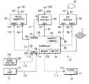
- the object locator system 10includes a two-way paging system 12 , a satellite navigation system shown as a GPS system 50 and the object locator 42 . While the described embodiment shows a GPS system for illustrative purposes, it is intended to function with other satellite navigation systems such as, for example, the Russian GLONASS system, which provide location information in the vicinity of the earth.
- the two-way paging system 12is a conventional paging system that is well known in the art, for example, such as illustrated and described in U.S. Pat. No. 5,423,056 issued Jun. 6, 1995 to Lindquist, et al.
- the two-way paging system 12interacts with a base station 18 over a transmit path 14 and a receive path 16 .
- the base station 18which may also be called a host, designating the position of a system user, may be a two-way pager and may include a telephone or a keyboard or the like or may have an input 20 for receiving a dialed-in telephone number from telephone set 24 along communications path 22 or from wireless telephone set 25 over communications path 31 .
- the input 20is responsive to dual tone multi-frequency (DTMF) tones transmitted by telephone set 24 .
- the input 23is responsive to digital signals transmitted over path 21 from a key array 13 .
- Base station 18further has an output 26 from which location data to be displayed travels along path 28 to display 30 .
- Display 30may be configured to display location information in any of several forms, for example, text, figures, graphics, or numbers.
- the object locator system 10 of the present disclosureincludes an object locator 42 .
- object locator 42In one of its operational modes, as a two-way paging transceiver, object locator 42 includes an input 40 coupled to an antenna 36 along cable 38 for receiving signals transmitted by two-way paging system 12 along path 32 and for transmitting paging signals to the two-way paging system 12 along path 34 .
- the object locator 42also includes an input 44 for receiving from a GPS system 50 location information signals along path 52 to be intercepted by antenna 48 and conducted to the object locator 42 along path 46 to input 44 .
- the GPS system 50is of a conventional design well known in the art, an example of which is described in U.S. Pat. No. 5,726, 660 issued Mar.
- location information signalsmay be received from the GLONASS satellite system or any other satellite navigation system providing location information by the use of a receiving system configured for such reception.
- object locator 42is intended to be carried or attached to an individual, an object or an animal to be located or tracked by the object locator system 10 of the present disclosure.
- a userenters the system from the base station 18 by dialing the telephone number address corresponding to the object locator 42 by using telephone set 24 or wireless telephone set 25 .
- the DTMF signalthen travels along path 22 to input 20 of base station 18 or via wireless path 31 where it is converted to a paging transmit signal and transmitted from antenna 15 along transmit path 14 to the two-way paging system 12 .
- the usermay enter an electronic address via the key array 13 connected to the base station 18 along path 21 to an input 23 or via a virtual key array (not shown) incorporated in the base station 18 .
- the resulting paging transmit signalis transmitted from port 19 to antenna 15 through path 17 and further transmitted along transmit path 14 to the two-way paging system 12 .
- the two-way paging system 12relays the paging message via transmit path 32 to the antenna 36 coupled to the object locator 42 .
- the object locator 42processes the request for location information transmitted by base station 18 , obtains location information from the global positioning satellite system 50 and transmits a response containing the location information from antenna 36 along path 34 to the two-way paging system 12 which, in turn, relays the location information signal along path 16 to antenna 15 of the base station 18 for processing and display on display 30 .
- Multiple object locators 42may be in individual communication with base station 18 by virtue of each object locator having a specific electronic address.
- each object locator 42may be assigned multiple addresses. One address may be unique to the specific locator while at least one additional address may be identical for all locators communicating with the base station whereby the base station may send simultaneous messages to multiple object locators.
- wireless paths 14 and 16 along with antenna 15may instead each comprise a standard telephone connection to a central office.
- the base station 18communicates directly over a wireless path with a compatible communications transceiver included in the object locator 42 . Such a system is described further in conjunction with FIG. 11 .
- the object locator 42is initialized by the user to define one or more geographic coordinates to define an area such as a yard. Only one position need be defined for a small area and only the corners of a large area need be defined, thus conserving memory requirements.
- the locator deviceis then attached to the animal.
- the object locator 42is adapted to become operational when the object locator 42 device is secured to the animal and power is coupled to the object locator 42 thereby allowing reception of GPS location information.
- the object locator 42may be set to monitor location signals continuously or periodically or selectively by a predetermined program.
- the object locator 43is activated to initiate a message to the base station 18 as will be described hereinbelow.
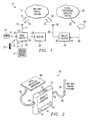
- FIG. 2there is illustrated a pictorial drawing of an object locator 42 of the illustrative embodiment as it may be typically configured with a two-way paging antenna 36 and a GPS receive antenna 48 .
- the two-way paging antenna 36is coupled to the object locator package 37 along cable 38 to an input 40 on the object locator package 37 .
- the GPS receive antenna 48is coupled along a cable 46 to an input 44 on the object locator package 37 .
- the two-way paging antenna 36 shown in FIG. 2is intended to represent the fact that this antenna in the object locator 42 is typically of the type found with two-way paging equipment. Such an antenna is typically mounted internal to the pager unit itself and is thereby necessarily of very small dimension.
- the GPS receive antenna 48is conventionally referred to as a “patch antenna” because of its flat, thin, rectangular shaped design.
- patch antennais intended to be disposed on an upward, relatively level surface in order to expose it to receive the relatively weak signals transmitted by the global positioning satellite system 50 from the satellites arrayed in the GPS system 50 .
- both of the antennae used in the systemmay be positioned for optimal reception and transmission and connected to the object locator package 37 using the flexible cables 38 and 46 respectively for the two-way paging antennae 36 and the GPS receive antenna 48 .
- a switch 55may be provided on the object locator 42 for activating or deactivating the object locator 42 .
- An alpha-numeric display 41may be included on the object locator package 37 to allow information stored in memory 68 to be viewed. To conserve space, the display 41 may allow a limited number of characters to be viewed at one time.
- a readout control switch 47 associated with display 41is operable to allow successive viewing of a sequence of data items or scrolling through lines of data.
- a test button 43is provided to allow the user to manually actuate object locator 42 to send a message to base station 18 thereby testing the communication links 34 and 16 .
- the object locator 42will likely be exposed to a variety of environmental conditions including exposure to water and temperature extremes. Accordingly, the package 37 containing the electronic circuitry should be resistant to water ingress to the electronic circuitry. The circuitry within the package should be designed for operation under wide temperature variations. Mechanisms for accomplishing such protection are well known in the art and will not be described here.
- FIGS. 3 a , 3 b and 3 cthere is illustrated a pictorial drawing of an object locator 42 mounted on the lower side of a collar 45 .
- a collar 45is configured for supporting an object locator 42 around the body or neck of an animal which is intended to be tracked or located by the object locator 10 of the present disclosure.
- the GPS antenna 48is attached to the collar diametrically opposite the position of the object locator. This is intentional as will be described hereinbelow.
- the object locatoris coupled to the GPS antenna 48 through a cable 46 which connects to the input 44 of the object locator 42 . This arrangement is illustrated in FIG.
- FIG. 3 amay be more clearly shown by looking at the cross section 3 b — 3 b illustrated in FIG. 3 b .
- Section 3 b — 3 ba side view of the object locator mounted on a collar is shown wherein collar 45 supports the object locator 42 at its lower point and supports the GPS antenna 48 at its diametrically opposite upper point.
- the GPS antenna 48is coupled through cable 46 to input 44 of the object locator 42 .
- a side view identified by cross section 3 c — 3 c in FIG. 3 cshows the opposite side of the collar-mounted object locator 42 assembly.
- Section 3 c — 3 cthere is shown the collar 45 which supports the object locator 42 at its lower end and the patch antenna or GPS antenna 48 at its diametrically opposite upper end. Also shown in the Section 3 c — 3 c is a representation of the two-way paging antenna 36 which is coupled to input 40 of the object locator 42 . It will be appreciated that many configurations are possible for arranging or attaching the object locator and its antennae to the collar 45 , including enclosing the GPS receive antenna 48 inside the collar 45 or consolidating the locator and antenna as a unit mounted on or in the collar. Alternatively, the locator and antenna may be distributively arranged on or in the collar.
- the greater mass of the object locator 42 relative to the mass of the GPS antenna 48 and the fact that they are mounted on diametrically opposite sides of the collar 45enables the object locator 42 to remain in the lowest possible position while the GPS receiving antenna remains in the highest possible position to optimize the reception from the GPS system 50 , though it is not imperative that the GPS antenna 48 remain in the highest possible position.
- the GPS antenna 48may be positioned within or around the collar 45 or integrated with the pager antenna 36 .
- a mechanismsuch as a clasp or buckle arrangement (not shown in FIGS. 3 a - 3 c ) may be provided to permit the collar 45 to be opened and closed for securing the collar around the neck or body of the animal to be tracked or located.
- Such clasp or bucklemay be electrically integrated with the collar and the electronic circuitry, e.g. constructed with an interlock, such that initial mating of the clasp or buckle will activate operation of the object locator 42 . Any subsequent opening of the clasp or buckle may initiate an alarm message to the base station indicating deactivation of the object locator 42 except when a message sent to the object locator 42 by the base station 18 caused a previous, intentional deactivation.
- the object locator 42may be deactivated by a signal from the base station 18 , allowing the collar 45 to be removed without causing an alarm indication.
- a collar activating switch 55may be imbedded in the collar 45 or located on the object locator 42 attached to the collar 45 .
- a security device 49preferably a flexible metal cable represented by the dashed line in FIGS. 3 a , 3 b and 3 c , which is coupled electrically to the buckle or clasp and through ports 51 and 53 to object locator 42 , provides a closed electrical circuit when the clasp or buckle of the collar 45 closed. Cutting or otherwise breaking security device 49 will cause object locator 42 to immediately initiate a preformatted message alerting the user of the security break.
- the object locator 42may also be activated upon closing the clasp or buckle when placing the collar 45 around the body of the animal or other object to be tracked or located.
- a manual test of the communication link 34 and 16 between the object locator 42 and the base station 18may be actuated by manually operated switch 43 . To perform the test, actuation of switch 43 causes the controller to send a preformatted message stored in memory 68 within the object locator 42 over communication link 34 and 16 to the base station 18 .
- FIG. 4there is illustrated a block diagram for the object locator 42 of the object locator system 10 of the present disclosure.
- a paging receiver 60is shown coupling a data output 62 along path 64 to an input of controller 66 .
- Controller 66includes a memory 68 for the storage of location data and a battery 70 for powering the object locator 42 .
- This battery 70is, in the present disclosure, a rechargeable battery.
- This battery 70can be a NiCad battery, a Lithium battery or any rechargeable battery, though one-use batteries may also be used.
- a solar cell 71 and associated charging circuitry(not shown) is provided for charging the battery 70 .
- Controller 66includes a control output 72 which is coupled along path 74 to a control input 76 of paging receiver 60 .
- Paging receiver 60receives paging communications via antenna 36 R which are coupled along cable 38 R to RF input 40 R of paging receiver 60 .
- GPS receiver 78for which provision is made to couple location data at an output 80 along path 82 to an input terminal 84 of controller 66 .
- GPS receiver 78further includes an enable input which is coupled from controller 66 at output 86 along path 88 to the enable input 90 of the GPS receiver 78 .
- the GPS receiver 78receives GPS signals from the global positioning satellite system 50 at antenna 48 which signals are coupled along path 46 to RF input 44 of the GPS receiver 78 .
- a paging transmitter 92which is configured to transmit the location data provided by controller 66 at output 98 along path 96 to the data input 94 of paging transmitter 92 .
- Controller 66also provides an enable output at output 100 along path 102 to the enable input 104 of paging transmitter 92 .
- the paging transmitter 92when enabled, transmits data received at the data input 94 and couples the signal to be transmitted from the output terminal 40 T along path 38 T to the paging transmitter antenna 36 T for radiation to the two-way paging system 12 . It will be appreciated that the paging system components, while shown as separate functional elements in FIG.
- FIG. 4may in fact be integrated into a single two-way paging transceiver which share a common antenna represented by reference number 36 .
- the illustration shown in FIG. 4is intended to provide clarity as to the signal paths that operate during the communication relationship of the object locator 42 with the two-way paging system 12 .
- a number of configurations for coupling the antenna to the paging transceiverare feasible, are well known in the art and will not be described further herein.
- signal detector 106having an output 108 which is coupled along path 110 to an enable input 112 of controller 66 .
- the signal detector 106represents any of several optional devices which may enable the more precise control of the object locator 42 by limiting the operation of the object locator 42 to certain external conditions outside the paging communications or the GPS reception areas by the object locator 42 .
- the signal detector 106provides an output whenever a threshold is crossed by signal energy received from an independent source, e.g., a beacon.
- This thresholdmay represent a predetermined perimeter beyond which the object locator 42 is enabled to operate and within which a position of the object locator would probably provide no useful information because the object locator may be within line of sight to the base station.
- Other thresholdsmay be expressed in terms of time or altitude or as an azimuth heading or simply an area defined by the uncertainty statistics of the position reported by GPS.
- the object locator 42may be programmed for operating an alarm or automatically transmitting location information to a base station when the object locator 42 moves outside a perimeter.
- Such perimetermay be programmed by physically positioning the object locator 42 at extremes of an area and, while the GPS receiver 78 is operating, storing in the object locator's memory 68 the coordinates reported, thus establishing a boundary outside of which the object locator 42 will automatically report a position. Additionally, the perimeter may be defined by at least one coordinate stored in the object locator memory 68 . The perimeter is then determined by selecting stored algorithms to define the limits of a circular or other geometrical shape outside of which the object locator 42 will automatically report a position.
- the coordinate positions of the corners of a rectangular areamay be obtained and stored.
- Each such positionis an origin or center of a circle, the circle representing the GPS system error (position uncertainty, specified as a radius) of the location data provided by the GPS system 50 .
- the enclosed areais defined by establishing straight lines tangent to the outer arcs of each adjacent pair of circles along the intended area border.
- the radius of the circlemay be, for example, approximately 5 meters (or a little over 16 feet) for civilian applications.
- a userwould position the object locator at the corners of the square located about 15 meters (about 48 feet) apart.
- Many other algorithms for specifying an enclosed areaare of course possible.
- a circle of radius of 5 meters, equivalent to an enclosed, circular area of diameter equal to 10 metersmay be appropriate.
- a single coordinate positionwould suffice to specify the enclosed area, beyond which the object locator 42 , upon activation, automatically obtains location of its current position outside the perimeter of the specified circle and reports it to the base station.
- the base stationin these examples, may simply be a pocket display pager carried by a user who may be within a specified circle (e.g., at the origin) or at some other location or even in motion with respect to the origin where the enclosed area is specified or with respect to the object locator.
- each of the major functional blocks shown in FIG. 4may be implemented singly or collectively into integrated circuit structure which may be configured to fit within a housing of very small dimensions.
- a pocket pagerthat typically occupies a volume of approximately three to five cubic inches may weigh approximately four to six ounces.
- the GPS receiver 78 , the controller 66 , the paging transmitter 92 and the paging receiver 60may be integrated into a single integrated circuit structure.
- the controller 66may comprise a single chip microprocessor or microcontroller or digital signal processor which may be programmed to provide a variety of functions and operational features. Such programs may be stored in memory 68 for use by the controller 66 in controlling the operation of the object locator 42 .
- the paging receiver 60 , the paging transmitter 92 and the GPS receiver 78while shown as functional blocks, in reality, each may have a number of complex functions incorporated therein. Thus, many configurations and functional operations are possible within the scope of the block diagram illustrated in FIG. 4 .
- the detailed description which followswill illustratively provide descriptions of some of the basic operational features of the object locator system 10 of the present disclosure. One such feature represented by the signal detector block 106 will be described hereinbelow in conjunction with FIG. 7 .
- FIG. 5there is illustrated a flowchart for the operation of the object locator 42 shown in FIG. 4 in the case where the user desires to determine the location of the object locator 42 .
- This circumstancemay represent any number of user activities including an owner's efforts to determine the location of a pet dog or a pet cat, for example.
- the operation illustrated in FIG. 5may also include a situation where an owner desires to track versus time, an object to which the object locator 42 is attached.
- the flowchart of FIG. 5may also illustrate the situation when the object locator 42 is attached to a person and it is desired to know the location of that person at some particular time or some other previous time as further described below.
- the flowbegins at block 202 with the start of the sequence of operations, which is followed by decision block 204 in which the object locator 42 seeks to determine whether a page requesting location information has been received by the input 40 of the two-way paging receiver 60 . If the result of this determination is in the negative, then the flow returns to the input of the decision block for a retry. If, however, the result of the query was affirmative, then the flow proceeds to block 206 in which the GPS receiver 78 is enabled to acquire the location coordinates of the object locator 42 by receiving signals from the global positioning satellite system 50 illustrated in FIG. 1 .
- the object locator 42Upon successfully acquiring the coordinates of the object locator 42 and thus of the individual object or animal to which the object locator 42 is attached, the object locator 42 then operates to store the coordinate information in block 208 by loading the coordinate information into the memory 68 of the controller 66 in the object locator 42 .
- coordinate informationmay be associated with a time stamp.
- time stampderived from the GPS satellite system, may then be stored in block 208 for later retrieval. Additionally, such coordinate information may further be associated with other data such as object locator 42 operational status or battery condition.
- the flowthen proceeds from block 208 , where the coordinates were stored in the memory 68 , to block 210 , wherein the object locator 42 is configured to transmit the coordinates in response to the request received over the two-way paging system 12 .
- the transmission of coordinateswill occur in the opposite direction utilizing the same two-way paging system 12 over which the request for location coordinates was received in block 204 .
- the flowproceeds to a timer block 212 which provides a measured interval of time during which the object locator 42 attempts to acquire the coordinates at the particular time from the GPS system 50 .
- a typical GPS systemoften takes a substantial amount of time to acquire location coordinate information from a sufficient number of satellites in order to fix the location of the object locator 42 with a sufficient degree of precision.
- the time requiredinvolves receiving several signals under conditions which may vary widely from instant to instant, which impairs the ability of the GPS receiver 78 as shown in FIG. 4 to obtain complete location data to respond to the request received by the paging receiver 60 in the object locator 42 .
- the time value represented by the timer operating in block 212may be on the order of five to ten minutes, for example. In block 212 , if the timer has not reached the time-out value, then the flow returns to the input of block 206 where the object locator 42 again attempts to acquire the coordinates from the GPS system 50 .
- FIG. 5thus illustrates a basic mode of operation of the object locator 42 . It will be appreciated that many variations on this basic operating mode are possible and may be used to enhance the operation of the object locator 42 . Such features may be programmed into the controller 66 of the object locator 42 .
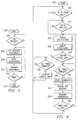
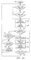
- FIG. 6there is illustrated a flowchart for the operation of the object locator 42 in the circumstance where it is activated, in this illustrative example, to obtain location information from the GPS receiver 78 and transmit coordinates only when the object locator 42 is in a position beyond a distance limit defining a designated area surrounding or relative to the base station or some other defined location such as an origin from which the request for location coordinates was initiated.
- the object locatoris activated to transmit location coordinates when it is secured to the object, power is coupled to the object locator and the object locator passes the perimeter of a defined enclosed area.
- the object locatormay also be activated to transmit location coordinates by remote command or query from a base station or periodically by a timer in the object locator controller.
- the flowchart in FIG. 6also shows additional steps in the operational sequence which may be used to enable and disable the GPS receiver 78 within the object locator 42 .
- the GPS receiver 78is typically a device which requires substantial electrical power to operate. It is prudent to minimize the power drawn from the object locator battery 70 in FIG. 4 by limiting the operating cycle of the GPS receiver 78 .
- the GPS receiver 78 in this exampleis permitted to become operational only long enough to obtain the coordinate information that is required by the object locator 42 .
- the flowproceeds from start block 220 to a decision block 222 to determine whether the object locator 42 has received a query from the base station 18 . If a query has not been received, such as occurs during an automatic mode or by command, the flow proceeds along the “N” path to a timer block 224 wherein the object locator 42 may operate a timed sequence to periodically enable the GPS receiver 78 to acquire location coordinates whether or not a query is received from the base station 18 . When the timer of block 224 times out, the flow proceeds along the “Y” path to a block 226 to enable the GPS receiver 78 .
- the automatic modeis overriden and the flow proceeds along the “Y” path to block 226 to enable the GPS receiver 78 .
- the flow in the object locator 42proceeds from block 226 to block 228 to acquire the coordinates of the location of the object locator 42 . Thereafter, the flow proceeds to decision block 229 to determine whether the object locator 42 is beyond a predetermined perimeter with respect to the base station 18 or other origin location which defines a designated area.
- the designated enclosed area surrounding the base station 18 or origindefines an area in which operation of the object locator 42 is inhibited because the object having the object locator 42 attached thereto is in the immediate vicinity of the base station 18 or is within the radius of uncertainty with respect to the origin as described hereinabove. Beyond the designated enclosed area the object locator 42 automatically reports location data to the base station 18 .
- the predetermined perimeter distance limit or radiusmay typically be set, for example, to approximate the boundary of the residence of the owner of a pet animal, beyond which it is desired to obtain location information of the pet animal provided by an object locator 42 (or, pet locator 42 in this example) attached to the pet. If the result of the determination in block 229 is negative, the flow proceeds along the “N” path to decision block 239 wherein a counter provides for a predetermined number of trials to establish whether the object locator 42 is beyond the predetermined limit required in block 229 . When the counter in block 239 completes the last count, the flow proceeds to a block 241 when the object locator 42 outputs a preformatted message to the base station 18 that the object locator is still within the predetermined limit.
- the flowproceeds along the “Y” path to the input of the decision block 222 .
- decision block 229if it is determined that the object locator 42 is beyond the predetermined limit, meaning the coordinates are to be stored, the flow proceeds along the “Y” path to block 240 wherein a counter provides for a predetermined number of trials to establish whether the object locator 42 is beyond the predetermined limit required in block 229 .
- the flowproceeds to block 230 to store and, in some cases, time stamp the location coordinates acquired from the GPS satellite during the step performed in block 228 .
- the enable signal applied to the enable terminal 90operates to awaken the GPS receiver 78 so that it may communicate with the GPS system and obtain location information coordinates for the object locator 42 .
- the flowproceeds from block 226 where the GPS receiver 78 is enabled to a block 228 where the object locator 42 acquires the coordinate information from the global positioning satellite system 50 .
- the controller 66 within the object locator 42upon acquiring the coordinates of the object locator 42 from the GPS receiver 78 , the controller 66 within the object locator 42 causes the location and time information to be stored in the memory 68 of the object locator 42 in the operational block 230 of FIG. 6 .
- the flowthen proceeds to a block 232 where the controller 66 operates to disable the GPS receiver 78 such that it will no longer continue to drain power from the battery, until the next time that it is desired to acquire coordinate information from the GPS system 50 .
- the flowproceeds to a block 234 wherein the object locator 42 provides the location data on output terminal 98 along path 96 to the data input 94 of the paging transmitter 92 .
- the location informationis then transmitted via the two-way paging system 12 to the base station 18 shown in FIG. 1 .
- the flowproceeds from block 234 following the transmission of the coordinate information to a time-out block 236 where a timer provides an interval of time in which the object locator 42 is permitted to acquire the coordinate information from the GPS system, thus maximizing the opportunity to acquire the coordinates before the object locator 42 becomes inactive.
- a timerprovides an interval of time in which the object locator 42 is permitted to acquire the coordinate information from the GPS system, thus maximizing the opportunity to acquire the coordinates before the object locator 42 becomes inactive.
- the time-out valuemay again typically be on the order of five to ten minutes, although the time duration may legitimately be any value that corresponds with the particular circumstances of use and, in fact, may be adjustable in some applications.
- the operationloops back around to the input of block 226 and enables the object locator 42 to continue attempting to acquire the location information from the GPS system.
- the flowproceeds along the “Y” path from block 236 back to the start of the sequence at the input to the decision block 222 where the object locator 42 is enabled to check whether the object locator 42 is positioned beyond the predetermined limit as previously explained.
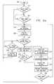
- FIG. 6 athere is illustrated a block diagram of a configuration that enables reporting the direction and rate of movement of the object to which collar 45 is attached.
- This embodimentis very similar to that shown in FIG. 6 and shares functional blocks—which have the same function and reference numbers—with FIG. 6 .
- the controller 66 within the object locator 42Upon acquiring the coordinates of the object locator 42 from the GPS receiver 78 , the controller 66 within the object locator 42 causes the location and time information to be stored in memory 68 of the object locator 42 in the operational block 230 of FIG. 6 a .
- the operational flow described in FIG. 6 aillustrates the operation in the case where the object locator is beyond the limit previously set as described hereinabove for FIG. 6 .
- the usermay desire to know the direction and rate of movement of the object locator 42 . Determination of the direction and rate requires analysis of a sequence of information containing position coordinates and the time at which each set of coordinate data were collected. In order for the calculation to be accurate and timely, the data must be current. Accordingly, the user may cause a message to be sent from the base station 18 to the object locator 42 to designate the number, N, of coordinate and time data sets to be taken and used in the calculation of the direction and rate of movement of the object locator 42 .
- the object locator 42receives the previously described message from the base station 18 , the flow described in FIG. 6 a begins at start block 220 .
- the flow in FIG. 6 abegins with start block 220 wherein a preformatted message indicating the number, N, of required samples of location and rate of movement data is sent from the base station 18 to the object locator 42 .
- the GPS receiveris enabled at block 226 and begins to acquire coordinates in block 228 . Since the object locator 42 in this illustrative example is already beyond the predetermined limit the decision block 229 passes the flow to block 230 .
- the flowthen proceeds to a decision block 233 wherein a counter provides for a predetermined number, N, of coordinate and time data sets to be stored and saved in memory 68 .
- the minimum required number of coordinate and time data sets to make a calculation of direction and rate of movement, of course,is two.
- Nmay provide more accurate, timely results.
- the flowproceeds to block 235 wherein data previously collected and stored in memory 68 is accessed and processed to determine the direction and rate of movement of the object locator 42 and then, flowing to block 237 , the resulting direction and rate calculations are stored in memory 68 .
- the flowthen proceeds to block 232 where the controller 66 operates to disable the GPS receiver 78 .
- the flowproceeds to block 234 wherein the object locator 42 provides the direction and rate of movement data on output terminal 98 along path 96 to the data input 94 of the paging transmitter 92 .
- the direction and rate of movement informationis then transmitted via the two way paging system 12 to the base station 18 shown in FIG. 1 .
- Messages reporting direction of movementare preformatted to transmit a symbol, such as an arrow, representing the direction of motion of the object locator in addition to alpha-numeric characters showing location.
- FIG. 6 bthere is illustrated a flow chart to provide for reporting the return of the object locator 42 to within the predetermined limit after initially going beyond the limit.
- This embodimentis very similar to that shown in FIG. 6 and shows functional block—which have the same functions and reference numbers—with FIG. 6 .
- decision block 229Upon either a base station query or a timed sequence (or duty cycle) query, decision block 229 outputs a negative result when the object locator 42 is now within the predetermined limit. The flow proceeds to decision block 231 to determine whether the object location 42 has previously been beyond the limit.
- the flowproceeds to blocks 230 , 232 and 234 wherein the object locator 42 reports, via a preformatted message retrieved from memory 68 , to the base station 18 that the object locator 42 is now within the predetermined limits, i.e., the pet animal or object has returned close to the base station.
- the reportmay be indicated at the base station 18 by a symbol or other characters associated with the information.
- the flowproceeds along the N path to the block 239 , the counter which regulates the number of trials for recognizing a beyond limit condition. Upon reaching the predetermined count in block 239 the flow proceeds to block 241 where a message “object locator is still within the limit” is issued to the base station 18 .
- the object locator 42there are defined four concentric geographic regions. In the center is the immediate vicinity of the base station 18 or near range which may, for example, be roughly equivalent to the residential yard of the owner of a pet that wears an object locator.
- the active range of the object locator 42is separated from the near range by a predetermined inside perimeter or limit.
- the outer range within which the object locator operation is marginally capable of reliably providing location informationis not limited. The report to the base station 18 of locations within this outer range may be accompanied by a preformatted message specific to this circumstance.
- such a message in this instancemight state: “The last known position and heading (of the object or pet) is” followed by the coordinates and information about the heading.
- the last geographic region, beyond the outer range and defined by the loss of signal from the base station 18is the far range, where the object locator is unable to provide location information.
- the predetermined inside perimeter limit and the predetermined outside perimeter limitbetween which lies the active, reliable range of the object locator.
- the inside perimeterwill depend, in general, upon the resolution parameters of the GPS system 50 .
- the outside perimetermay, generally, be defined by a signal strength parameter such as the reception strength of a beacon signal.
- FIG. 7there is illustrated a pictorial block diagram of one configuration for providing a predetermined limit signal to the object locator 42 .
- a base station 18coupled with its antenna 126 through a cable 128 and operating to produce a signal which is radiated according to the radiation pattern characteristic of the antenna 126 of the base station.
- an object locator 42which includes a signal detector block 120 coupled to an antenna 122 through a cable 124 . It will be noted that the base station 18 is operating in a transmit mode and the object locator 42 is operating in a receive mode via antenna 122 .
- the object locator 42by comparing the received signal strength of the signal transmitted by the base station from antenna 126 with a reference signal stored within the signal detector 120 , may determine whether it is near or far from the base station 18 . It is presumed in this example that the signal strength measured between the base station 18 and the object locator 42 falls off in a predictable manner as compared with the distance that separates the object locator 42 from the base station 18 . It will be appreciated that this technique may be used to define a predetermined inside perimeter limit signal that defines when (or where) the object locator is to begin providing location information as the animal or object wearing the object locator 42 moves away from the base station 18 . This technique may also be used to indicate when the object locator has moved—or is moving—past an outside perimeter, beyond the useful range of the object locator 42 .
- an alternative to comparing the limit signal with a reference valueis to simply utilize the signal-to-noise characteristics of the receiver in the object locator 42 .
- a limitis thereby provided.
- the limitmay be adjusted simply by adjusting the base station signal strength.
- a predetermined limitmay thus be established by controlling the signal strength of the base station 18 signal such that at an imaginary boundary 130 such as a predetermined outside perimeter surrounding base station 18 is defined.
- the signal strengthis of a sufficiently low value which can just be detected by the signal detector 120 in the object locator 42 at the imaginary boundary 130 .
- the object locator 42 antenna 122is greater than a distance indicated by the radius “r” from the base station 18 , then no signal will be detected (or it will be below an acceptable threshold) and the object locator 42 is presumed to be beyond the predetermined outside perimeter limit represented by the distance “r”, which may also be thought of as an acceptance radius. If, however, the object locator 42 receives or detects the signal emitted by the base station 18 (or it is above the predetermined threshold), then it is presumed that the antenna 122 of the object locator 42 is within the radius “r” and the object locator 42 may, at that point, be activated to acquire location information from the GPS system 50 and report it to the base station 18 .
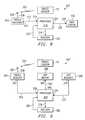
- the base station 302includes a paging receiver 304 which has a receiving antenna 306 coupled to the paging receiver 304 by a cable 308 .
- the output of paging receiver 304is supplied at an output 310 along path 312 to an input 314 of a processor 316 which receives and processes the location information for output or display.
- a processor 316which receives and processes the location information for output or display.
- the informationis stored along a path 318 in a register 320 from which the information can be retrieved along path 322 by the processor 316 for output at terminal 324 along path 326 to the input 328 of a data display 330 .
- the location informationis processed for display as data which may be in the form of degrees of longitude and latitude, the names of the closest major street intersections or in terms of polar coordinates such as an azimuth heading and a distance between the base station 302 and the object locator 42 .
- a base station 350which includes a paging receiver 304 .
- Paging receiver 304receives location information transmitted by object locator 42 over path 305 to the antenna 306 of the paging receiver 304 along cable 308 .
- Paging receiver 304is coupled from an output 352 along path 354 to an input 356 of processor 358 in the base station 350 .
- Processor 358may also have access to a register 380 along path 378 from which the processor 358 may further obtain stored location information along path 382 from register 380 .
- Such location informationis, of course, available from the GPS receiver 368 which is coupled at an output 370 along path 372 to an input 374 to processor 358 .
- This GPS receiver 368is part of base station 350 and enables the base station 350 to provide an enhanced display of the location information obtained from the object locator 42 .
- a GPS display 366that obtains data concerning the location coordinates from processor 358 at an output 360 which flows along path 362 to an input to the GPS display 366 at input 364 .
- the GPS display 366is configured to provide a map of the area that includes both the base station 350 and the object locator 42 , and thus display the relative position of each component of the object locator system 10 with respect to the other.
- a mapmay be shown with streets or thoroughfares indicated thereon and indicia included in the display showing the respective location of the base station 350 and of the object locator 42 .
- FIG. 10there is shown a flowchart of the operation of the combined units of the object locator system 10 of the present disclosure as illustrated in FIG. 1 .
- the flowbegins at block 402 where the routine starts and thereupon flows to a block 404 in which the base station 18 requests location information by paging the object locator 42 .
- the base station 18transmits a request for location information to the object locator 42 .
- the flowproceeds from block 404 to block 412 where the object locator 42 proceeds through the sequence to enable the GPS receiver 78 in order to obtain new location coordinate information.
- the object locator 42checks its own memory—see, for example, the block diagram of the object locator 42 shown in FIG.
- the flowproceeds to a block 424 wherein the base station 18 makes a determination as to whether it has received the requested coordinate information from the object locator 42 . If the result is affirmative, then the flow proceeds along the “Y” path to a block 428 where the base station 18 proceeds to output or display the coordinate information to the user at the base station 18 . Thereupon, the flow proceeds from block 428 to a block 430 wherein the routine ends.
- the base station 18determines whether it did not receive the coordinate information as requested, then the flow proceeds to block 426 along the “N” path to a decision block 426 .
- the base station 18determines whether the most recent page of the object locator 42 was, in fact, the last attempt permitted within the protocol for the base station operation. If the result is affirmative, then the flow proceeds along the “Y” path to block 418 where the object locator 42 operates to disable the GPS receiver 78 so that it no longer uses power from the battery 70 of the object locator 42 and thereafter proceeds to block 430 where the routine ends. If, however, the result of the determination in block 426 was negative, then the flow returns to the start of the routine at the input to block 404 where the base station 18 re-attempts to page the object locator 42 .
- the object locator 42checks to determine whether location coordinate information is, in fact, in the memory 68 of the object locator 42 . If the result is negative, the flow proceeds along the “N” path to block 414 where the object locator 42 acquires the new coordinate information and, as previously described, proceeds in block 416 to store the new coordinate information in memory 68 of the object locator 42 . The flow then returns to the input of block 412 wherein the GPS receiver 78 is enabled.
- the above noted object location systemwas disclosed as being utilized in conjunction with a pet, such that the pet owner can determine the location of their wayward pet.
- the locatoras described hereinabove, in one embodiment, is triggered to determine the location of the pet in response to receiving a signal from a paging system.
- the paging systemutilizes existing infrastructure in order to direct a message over a wireless link to a moving object, such as the pet. This only requires the inclusion of a paging receiver tuned to the frequency of the paging transmitters. Of course, there are multiple paging transmitters disposed about any given area. If the pet wandered outside of the range of all of these paging transmitters, then the system will not work. This would then, in the alternative, require a direct RF link to the pet.
- the locator 42will do one of two things. First, it could merely search its own memory to determine if location coordinates are stored therein from a previous acquisition operation of the GPS system. If so, these could be transmitted back to the requester. Alternatively the GPS system is turned on in response to receiving the request and then the location determined. Of course, as described hereinabove, there are provisions made for situations wherein the GPS system cannot be acquired.
- the disclosed embodimentsets forth the use of a two-way pager.
- These two-way pagersare desirable in that they make use of the existing infrastructure of the paging system. This is facilitated by the inclusion of a plurality of receivers at each of the paging towers or paging “sticks” which allow the signal to be received and forwarded back to a central station. This central station then processes the information received and forwards it to the user.
- This informationis in the form of coordinates. This coordinate information can then be relayed back to the user in any number of ways. It could actually be forwarded via a paging channel to the user, which might result in a latency of approximately two to five minutes.
- the two-way system that can be utilizedis a conventional system, one example of such a conventional system described in U.S. Pat. No. 5,708,971, issued Jan. 13, 1998, entitled “TWO-WAY PAGING SYSTEM AND APPARATUS,” which is incorporated herein by reference.
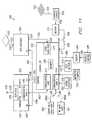
- the object locator 500comprises three major circuit blocks, a controller 502 , a GPS receiver 504 and a communication transceiver 506 .
- controller 502which may be a standard type microcontroller or microprocessor, is a memory 508 .
- Memory 508may include random access memory (RAM), non-volatile RAM or some form of read-only memory (ROM).
- Controller 502further includes a location data port 510 for receiving location data from GPS receiver 504 .
- Controller 502also includes a first communication port 512 for exchanging data with communication transceiver 506 .
- Controller 502further includes a third communication port 514 for exchanging data with an infrared data port 562 or an RF data port 564 .
- the datais exchanged between the third communication port 514 along a bidirectional data bus 560 which couples the third communication port 514 with a data bus selector 566 which selects between a data bus 560 A coupled to infrared data port 562 or couples via data bus 560 B to RF data port 564 .
- a rechargeable battery 516which may receive energy during recharging from solar cell 552 which is coupled along a path 554 to a charging circuit 556 which in turn is coupled to the rechargeable battery 516 along a path 558 .
- Power from the rechargeable battery 516is coupled along path 568 which includes an SPST switch 570 in series with path 568 for controlling the application of power to a terminal 571 on the controller 568 .
- Poweris connected from the terminal 571 to the GPS receiver 504 and the communications transceiver 506 along a path not shown in FIG. 11 for clarity.
- the charging circuit 556may be configured otherwise than with connection to a solar cell 552 .
- charging circuit 556may be a mechanical electric generator actuated by movements of object locator 500 when attached to a wearer of the object locator 500 .
- the GPS receiver 504receives signals at an input 518 from a patch antenna 520 via a path 522 .
- the output of the GPS receiver 504is coupled from an output 524 along a path 526 to an input terminal of the location data port 510 within controller 502 .
- GPS receiver 504is enabled by a control signal originating within controller 502 and coupled from an output 550 along a path 544 to an enable terminal of GPS receiver 504 .
- the communication transceiver 506includes a duplexor 534 which interfaces between the transmitter 530 and receiver 532 portions of the communication transceiver 506 and a dual mode antenna 536 via a transmission line 538 .
- Duplexor 534provides the interface between the respective transmit and receive modes during the operation of commination transceiver 506 , enabling the communication transceiver 506 to use a common antenna 536 .
- the transmitter portion 530 of communication transceiver 506is enabled for its operation along a path 546 originating in controller 502 and coupled from an output 550 to an enable terminal on transmitter 530 .
- the receiver portion 532 of communication transceiver 506is enabled by a control signal originating within controller 502 and coupled from the control outputs 550 along a path 548 to an enable terminal of receiver 532 .
- the signal outputs from communication transceiver 506are coupled from the receiver 532 via a second communication port 540 along a path 542 to an input of the first communication port 512 within controller 502 .
- Signals to be transmitted, originating within controller 502are coupled from first communication port 512 along the bidirectional data path 542 to an input terminal of the second communication port 540 coupled therefrom into the transmitter 530 within communication transceiver 506 .
- a display 564is provided to display data coupled along a path 566 from the controller 502 .
- the display 564may be typically a liquid crystal display having a capability of a small number of lines of text or symbols.
- the display 564may be caused to access data within controller 502 by the use of a readout control 568 which is coupled to the display along a path 570 .
- Readout control 568may be used to activate or deactivate the display, to scroll through various lines of data available for display or to select particular information to be displayed.
- a test button 572is also coupled to controller 502 via a path 574 which enables the user to manually actuate the object locator 500 to cause an operational test according to a routine stored within controller 502 to check various selected functions of the object locator 500 .
- Another device coupled to controller 502includes a magnetic compass 576 which provides an output signal along a path 578 to the controller 502 to provide information regarding the direction or heading of successive coordinate positions obtained and reported by the object locator 500 .
- a signal detector 580provides an output along a path 582 to the controller 502 when a parameter of the RF signals received by the object locator 500 exceed a predetermined threshold for the purpose of determining whether or not the object locator 500 is within or outside of the useful operating range or to define the minimum distance of the base station location before which the object locator 500 is not enabled to operate and obtain location coordinate data because the object locator or the pet locator is attached to an object or a pet animal which is very close to the base station and, for example, line of sight distances short enough for accurate and ready visual location of the object or pet.
- FIG. 11represents a composite embodiment of the object locator 500 with a selection of typical features to illustrate some of the possible functions that may be accomplished with the object locator 500 of the present disclosure.
- the various features illustrated in FIG. 11may be useful in the following ways.
- the memory 508 in controller 502may contain information as to the wearer's name, it's home address, a contact telephone number, vaccination status, veterinarian name and any other pertinent information that would be appropriate for an object locator 500 worn by a pet animal.
- a program in controller 502may be organized to store a portion of the operational data in a non-volatile memory within memory 508 for purposes of data backup. Similarly, location and associated time data may be stored for recall during operations which calculate direction and rate of movement information for transmitting to the base station along with the current coordinate information.
- the information stored in memory 508such as the wearer's name, home address, contact telephone number, vaccination status, veterinarian's name and the like may also be output to the display 564 by operation of the readout control 568 . This particular feature enables someone who finds the pet animal wearing object locator 500 to access the information stored within the object locator memory 508 and take appropriate action to return the pet to its owner or to render assistance to the pet if such assistance is indicated.
- one of the functions of the signal detector 580is to provide an indication when the object locator is about to move beyond its normal range of operation with respect to the base station and send a message to the base station indicating that the object locator 500 is about to become out of communication with the base station.
- the object locator 500is enabled to send a message to the base station if the satellite signal is lost, that is, the GPS receiver 504 is no longer receiving location information transmissions from the global satellite system.
- the magnetic compass 576may be activated to send direction information to the base station if the satellite signal is lost thereby providing information as to the last known location and heading of the object locator 500 .
- the infrared data port 562 and the RF data port 564are provided to write or read data to or from the memory 508 in controller 502 via the third communication port 514 .
- the infrared data port 562may typically include an optical transducer which is not shown for clarity and associated interfacing circuitry also not shown between the optical transducer and the controller 502 .
- the optical transducer and the associated interface circuitryare well known in the art and will not be further described herein.
- datamay be downloaded from the object locator 500 via the infrared data port 562 as an alternative to sending a communication command from the base station to the object locator 500 .
- datamay also be downloaded from the object locator 500 through the RF data port 564 as an alternate technique.
- datamay be uploaded to the object locator through either the infrared data port 562 or the RF data port 564 by appropriately selecting the data bus selector 562 to couple the data to the third communication port 514 in controller 502 .
- a pet owner desiring to use the pet locatorcontacts and subscribes to a paging service and obtains a two-way paging transceiver or, “pager,” which may or may not be included in the purchase price of the pet locator.
- the owner with the pagerbecomes the host or base station.
- the pet locatoris attached to the pet and the pet locator energized, typically by a switch on the pet locator assembly to activate the pet locator.
- the ownerdefines a designated enclosed area substantially surrounding the location of the host, e.g., a residence lot. The center of this enclosed area may be called an origin.
- This designationallows the pet locator to become active only when it is outside or beyond the perimeter of the designated enclosed area, where it can obtain location information about its location from the global positioning satellite system and communicate it to the host. Reports of location data may be transmitted automatically at regular intervals under the control of the pet locator or, alternatively it may be transmitted upon a request transmitted from the host or base station.
- An advantage of the “automatic reporting” pet locator system of the present disclosureis that once the user or pet owner becomes a subscriber to the paging system (any conventional two-way paging system will suffice) and installs and energizes, i.e., activates the pet locator by defining a designated area, no other action is required other than to observe the readout of the location data at the host location or base station.
- the installation proceduredesignates or enters the location of the host and defines the boundary or perimeter of the designated area.
- the boundary of the designated areamay be set by entering the coordinates of a single location, e.g., the farthest or other corner of the user's residence property or even a central location.
- the designated areawill approximate, for example, a circle centered at the host location and having a radius equal to the distance from the center at the specified single coordinate location to the perimeter of the circle defining the range of error or position uncertainty which is provided by the GPS system along with the location data.
- the boundary of the designated areamay also be set by the owner entering the coordinates of a plurality of location points to designate a specific area or perhaps, a non-circular area.
Landscapes
- Engineering & Computer Science (AREA)
- Physics & Mathematics (AREA)
- General Physics & Mathematics (AREA)
- Radar, Positioning & Navigation (AREA)
- Business, Economics & Management (AREA)
- Remote Sensing (AREA)
- Health & Medical Sciences (AREA)
- Child & Adolescent Psychology (AREA)
- General Health & Medical Sciences (AREA)
- Emergency Management (AREA)
- Computer Networks & Wireless Communication (AREA)
- Economics (AREA)
- Development Economics (AREA)
- Entrepreneurship & Innovation (AREA)
- Human Resources & Organizations (AREA)
- Marketing (AREA)
- Operations Research (AREA)
- Quality & Reliability (AREA)
- Strategic Management (AREA)
- Tourism & Hospitality (AREA)
- General Business, Economics & Management (AREA)
- Theoretical Computer Science (AREA)
- Position Fixing By Use Of Radio Waves (AREA)
- Mobile Radio Communication Systems (AREA)
Abstract
Description
Claims (25)
Priority Applications (4)
| Application Number | Priority Date | Filing Date | Title |
|---|---|---|---|
| US09/860,375US6480147B2 (en) | 1999-06-18 | 2001-05-18 | Portable position determining device |
| US10/292,888US7113126B2 (en) | 1999-06-18 | 2002-11-11 | Portable position determining device |
| US11/446,318US7336227B2 (en) | 1999-06-18 | 2006-06-02 | Portable position determining device |
| US12/036,913US7764228B2 (en) | 1999-06-18 | 2008-02-25 | Portable position determining device |
Applications Claiming Priority (4)
| Application Number | Priority Date | Filing Date | Title |
|---|---|---|---|
| US14004099P | 1999-06-18 | 1999-06-18 | |
| US09/362,788US6172640B1 (en) | 1999-06-18 | 1999-07-28 | Pet locator |
| US09/678,571US6441778B1 (en) | 1999-06-18 | 2000-10-03 | Pet locator |
| US09/860,375US6480147B2 (en) | 1999-06-18 | 2001-05-18 | Portable position determining device |
Related Parent Applications (1)
| Application Number | Title | Priority Date | Filing Date |
|---|---|---|---|
| US09/678,571ContinuationUS6441778B1 (en) | 1999-06-18 | 2000-10-03 | Pet locator |
Related Child Applications (1)
| Application Number | Title | Priority Date | Filing Date |
|---|---|---|---|
| US10/292,888ContinuationUS7113126B2 (en) | 1999-06-18 | 2002-11-11 | Portable position determining device |
Publications (2)
| Publication Number | Publication Date |
|---|---|
| US20020003493A1 US20020003493A1 (en) | 2002-01-10 |
| US6480147B2true US6480147B2 (en) | 2002-11-12 |
Family
ID=27385440
Family Applications (5)
| Application Number | Title | Priority Date | Filing Date |
|---|---|---|---|
| US09/678,571Expired - Fee RelatedUS6441778B1 (en) | 1999-06-18 | 2000-10-03 | Pet locator |
| US09/860,375Expired - LifetimeUS6480147B2 (en) | 1999-06-18 | 2001-05-18 | Portable position determining device |
| US10/292,888Expired - Fee RelatedUS7113126B2 (en) | 1999-06-18 | 2002-11-11 | Portable position determining device |
| US11/446,318Expired - Fee RelatedUS7336227B2 (en) | 1999-06-18 | 2006-06-02 | Portable position determining device |
| US12/036,913Expired - Fee RelatedUS7764228B2 (en) | 1999-06-18 | 2008-02-25 | Portable position determining device |
Family Applications Before (1)
| Application Number | Title | Priority Date | Filing Date |
|---|---|---|---|
| US09/678,571Expired - Fee RelatedUS6441778B1 (en) | 1999-06-18 | 2000-10-03 | Pet locator |
Family Applications After (3)
| Application Number | Title | Priority Date | Filing Date |
|---|---|---|---|
| US10/292,888Expired - Fee RelatedUS7113126B2 (en) | 1999-06-18 | 2002-11-11 | Portable position determining device |
| US11/446,318Expired - Fee RelatedUS7336227B2 (en) | 1999-06-18 | 2006-06-02 | Portable position determining device |
| US12/036,913Expired - Fee RelatedUS7764228B2 (en) | 1999-06-18 | 2008-02-25 | Portable position determining device |
Country Status (1)
| Country | Link |
|---|---|
| US (5) | US6441778B1 (en) |
Cited By (59)
| Publication number | Priority date | Publication date | Assignee | Title |
|---|---|---|---|---|
| US20020038392A1 (en)* | 1999-10-22 | 2002-03-28 | Carlos De La Huerga | Method and apparatus for controlling an infusion pump or the like |
| US20020059067A1 (en)* | 2000-10-11 | 2002-05-16 | Nissan Motor Co., Ltd. | Audio input device and method of controling the same |
| US20020098851A1 (en)* | 2001-01-24 | 2002-07-25 | Motorola Inc. | Method and system for validating a mobile station location fix |
| US20020119791A1 (en)* | 2001-02-28 | 2002-08-29 | Zhongze Bai | Method and system for locating target destinations within short ranges |
| US20020169539A1 (en)* | 2001-03-28 | 2002-11-14 | Menard Raymond J. | Method and system for wireless tracking |
| US20020177428A1 (en)* | 2001-03-28 | 2002-11-28 | Menard Raymond J. | Remote notification of monitored condition |
| US20020196151A1 (en)* | 2000-12-26 | 2002-12-26 | Troxler Robert Ernest | Large area position/proximity correction device with alarms using (D)GPS technology |
| US20030120522A1 (en)* | 2001-12-20 | 2003-06-26 | Robert Uyeki | Vehicle monitoring and reservation system |
| US6665613B2 (en)* | 2001-09-25 | 2003-12-16 | Lojack Corporation | Method of and apparatus for dynamically GoeFencing movable vehicle and other equipment and the like |
| US6674368B2 (en) | 2000-08-28 | 2004-01-06 | Continental Divide Robotics, Inc. | Automated tracking system |
| US20040012519A1 (en)* | 1999-06-18 | 2004-01-22 | Jennifer Durst | Portable position determining device |
| US20040198332A1 (en)* | 2002-11-27 | 2004-10-07 | Lundsgaard Soren K. | System and method of automatically answering calls in a wireless communication device |
| US20040247086A1 (en)* | 2001-02-26 | 2004-12-09 | Royal Thoughts, Llc | Emergency response information distribution |
| US20050073409A1 (en)* | 1999-06-18 | 2005-04-07 | Jennifer Durst | Object locator |
| US20050186968A1 (en)* | 1999-06-18 | 2005-08-25 | Jennifer Durst | Mobile object locator |
| US6960998B2 (en) | 1998-10-23 | 2005-11-01 | Royal Thoughts, Llc | Bi-directional wireless detection system |
| US20050253703A1 (en)* | 2002-12-23 | 2005-11-17 | Tianqing He | Systems, methods, and computer program products for automatic tracking and/or remote monitoring of nuclear gauges and/or data communication therewith |
| US6967562B2 (en) | 2002-02-22 | 2005-11-22 | Royal Thoughts, Llc | Electronic lock control and sensor module for a wireless system |
| US20060202818A1 (en)* | 2005-03-09 | 2006-09-14 | Greenberg Stephen J | Pet tracking systems, other tracking systems, and portable virtual fence |
| US20070063911A1 (en)* | 2003-06-16 | 2007-03-22 | Davidson D | Cellular antenna and systems and methods therefor |
| US20070146199A1 (en)* | 2005-12-28 | 2007-06-28 | Giga-Byte Communications Inc. | Position data exchange systems, mobile communication devices, and methods |
| US20070262853A1 (en)* | 2006-05-05 | 2007-11-15 | Black & Decker Inc. | Vehicle alarm |
| US20070279220A1 (en)* | 2006-06-05 | 2007-12-06 | Karen Wilcox | Multiple article locating system and associated method |
| US20080036610A1 (en)* | 2006-08-08 | 2008-02-14 | Garmin Ltd. | Animal tracking apparatus and method |
| US20080055155A1 (en)* | 2006-08-29 | 2008-03-06 | Hensley Charles R | Object identity and location tracking system |
| US20080055047A1 (en)* | 2006-08-31 | 2008-03-06 | Semiconductor Energy Laboratory Co., Ltd. | Semiconductor device |
| US7382317B1 (en)* | 2006-10-26 | 2008-06-03 | Gps International Technologies, Inc. | Two-stage location system |
| US20080262780A1 (en)* | 2002-10-11 | 2008-10-23 | Troxler Electronic Laboratories, Inc. | Paving-Related Measuring Device Incorporating a Computer Device and Communication Element Therebetween and Associated Method |
| US20080300712A1 (en)* | 2007-05-29 | 2008-12-04 | Guenter Zachmann | Method For Tracking and Controlling Grainy and Fluid Bulk Goods in Stream-Oriented Transportation Process Using RFID Devices |
| US20090061941A1 (en)* | 2006-03-17 | 2009-03-05 | Steve Clark | Telecommunications antenna monitoring system |
| US20090150003A1 (en)* | 2007-11-16 | 2009-06-11 | Jordan B Delano | Turf Irrigation System |
| US20100009697A1 (en)* | 2008-07-08 | 2010-01-14 | Hong Fu Jin Precision Industry (Shenzhen) Co., Ltd. | Mobile communication device capable of self-reporting location and method thereof |
| US20100127919A1 (en)* | 2008-11-21 | 2010-05-27 | Zoombak Llc | Geo-Fence With Minimal False Alarms |
| US20100164712A1 (en)* | 2004-12-09 | 2010-07-01 | Dean John William Corrigan | Communications system |
| US7848905B2 (en) | 2000-12-26 | 2010-12-07 | Troxler Electronic Laboratories, Inc. | Methods, systems, and computer program products for locating and tracking objects |
| US7864057B2 (en) | 2006-09-13 | 2011-01-04 | Perfectech, Inc. | Pet locating device |
| US20110018759A1 (en)* | 2009-07-23 | 2011-01-27 | Broadcom Corporation | Coupled gps phone and navigation system |
| US8060109B2 (en) | 1997-08-04 | 2011-11-15 | Enovsys Llc | Authorized location reporting mobile communication system |
| US20130214926A1 (en)* | 2012-02-21 | 2013-08-22 | Htc Corporation | Method for reminding objects being away and communication device and computer readable medium using the same method |
| US9031581B1 (en) | 2005-04-04 | 2015-05-12 | X One, Inc. | Apparatus and method for obtaining content on a cellular wireless device based on proximity to other wireless devices |
| US9467968B2 (en) | 2013-10-07 | 2016-10-11 | Ickovic & Bliss, Inc. | Wearable mobile broadcasting recovery system and device |
| US9961884B1 (en) | 2013-03-15 | 2018-05-08 | GPSip, Inc. | Wireless location assisted zone guidance system compatible with large and small land zones |
| US10064390B1 (en) | 2013-03-15 | 2018-09-04 | GPSip, Inc. | Wireless location assisted zone guidance system incorporating a multi-zone containment area |
| US10080346B2 (en) | 2013-03-15 | 2018-09-25 | GPSip, Inc. | Wireless location assisted zone guidance system |
| US10165755B1 (en) | 2013-03-15 | 2019-01-01 | GPSip, Inc. | Wireless location assisted zone guidance system region lookup |
| US10165756B1 (en) | 2014-03-18 | 2019-01-01 | GPSip, Inc. | Wireless location assisted zone guidance system incorporating a rapid collar mount and non-necrotic stimulation |
| US10172325B1 (en) | 2013-03-15 | 2019-01-08 | GPSip, Inc. | Wireless location assisted zone guidance system incorporating dynamically variable intervals between sequential position requests |
| US20190051130A1 (en)* | 2002-05-08 | 2019-02-14 | Resource Consortium Limited | Method and System for Remotely Monitoring a User |
| US10251371B1 (en) | 2014-03-18 | 2019-04-09 | GPSip, Inc. | Wireless location assisted zone guidance system incorporating a system and apparatus for predicting the departure of an animal from a safe zone prior to the animal actually departing |
| US10292365B1 (en) | 2013-03-15 | 2019-05-21 | GPSip, Inc. | Wireless location assisted zone guidance system incorporating shepherding of wayward dogs |
| US10342218B1 (en) | 2013-03-15 | 2019-07-09 | GPSip, Inc. | GPS dog fence incorporating location guidance and positive reinforcement training |
| US10470437B1 (en) | 2013-03-15 | 2019-11-12 | GPSip, Inc. | Wireless location assisted zone guidance system |
| US10624319B2 (en) | 2014-03-18 | 2020-04-21 | GPSip, Inc. | Wireless location assisted zone guidance system incorporating a rapid collar mount and non-necrotic stimulation |
| WO2020142089A1 (en) | 2018-12-31 | 2020-07-09 | GPSip, Inc. | Wireless location assisted zone guidance system incorporating a rapid collar mount and non-necrotic stimulation |
| US10715949B2 (en) | 2014-12-08 | 2020-07-14 | Alibaba Group Holding Limited | Determining timing for determination of applicable geo-fences |
| WO2021055883A2 (en) | 2019-09-18 | 2021-03-25 | GPSip, Inc. | Wireless location assisted zone guidance system incorporating secure transmission of location |
| US11713968B2 (en) | 2018-03-17 | 2023-08-01 | GPSip, Inc. | Wireless location assisted zone guidance system incorporating secure transmission of location |
| US11778420B2 (en) | 2020-06-29 | 2023-10-03 | Ickovic & Bliss, Inc. | Systems, methods, and program products for digital PET identification |
| US12171192B1 (en) | 2022-02-14 | 2024-12-24 | GPSip, Inc. | Graphical shepherding |
Families Citing this family (152)
| Publication number | Priority date | Publication date | Assignee | Title |
|---|---|---|---|---|
| US6988466B2 (en)* | 1999-11-10 | 2006-01-24 | Birdquest, Llc | Apparatus and method for rotating avian enclosures |
| US6975941B1 (en) | 2002-04-24 | 2005-12-13 | Chung Lau | Method and apparatus for intelligent acquisition of position information |
| US7212829B1 (en) | 2000-02-28 | 2007-05-01 | Chung Lau | Method and system for providing shipment tracking and notifications |
| US7403972B1 (en) | 2002-04-24 | 2008-07-22 | Ip Venture, Inc. | Method and system for enhanced messaging |
| US7321774B1 (en) | 2002-04-24 | 2008-01-22 | Ipventure, Inc. | Inexpensive position sensing device |
| US7366522B2 (en) | 2000-02-28 | 2008-04-29 | Thomas C Douglass | Method and system for location tracking |
| US7218938B1 (en) | 2002-04-24 | 2007-05-15 | Chung Lau | Methods and apparatus to analyze and present location information |
| US6980813B2 (en) | 2000-07-14 | 2005-12-27 | Norbelle, Llc | Locating system and method |
| US7474896B2 (en) | 2000-07-14 | 2009-01-06 | Norman Mohi | Locating system and method |
| US9292516B2 (en)* | 2005-02-16 | 2016-03-22 | Sonic Solutions Llc | Generation, organization and/or playing back of content based on incorporated parameter identifiers |
| US7779097B2 (en)* | 2000-09-07 | 2010-08-17 | Sonic Solutions | Methods and systems for use in network management of content |
| US7346347B2 (en) | 2001-01-19 | 2008-03-18 | Raze Technologies, Inc. | Apparatus, and an associated method, for providing WLAN service in a fixed wireless access communication system |
| US20090111457A1 (en)* | 2007-10-31 | 2009-04-30 | Raze Technologies, Inc. | Wireless communication system and device for coupling a base station and mobile stations |
| US6798391B2 (en)* | 2001-01-02 | 2004-09-28 | Xybernaut Corporation | Wearable computer system |
| EP1385374B1 (en)* | 2001-03-22 | 2013-07-17 | Nokia Siemens Networks Oy | Animal data gathering method and device |
| US6614392B2 (en)* | 2001-12-07 | 2003-09-02 | Delaware Capital Formation, Inc. | Combination RFID and GPS functionality on intelligent label |
| US20030109267A1 (en)* | 2001-12-12 | 2003-06-12 | Innovance Networks | Network element locating system |
| US6731239B2 (en)* | 2002-01-18 | 2004-05-04 | Ford Motor Company | System and method for retrieving information using position coordinates |
| US9049571B2 (en) | 2002-04-24 | 2015-06-02 | Ipventure, Inc. | Method and system for enhanced messaging |
| US9182238B2 (en) | 2002-04-24 | 2015-11-10 | Ipventure, Inc. | Method and apparatus for intelligent acquisition of position information |
| US20030218537A1 (en)* | 2002-05-21 | 2003-11-27 | Lightspace Corporation | Interactive modular system |
| US6874447B1 (en)* | 2002-06-04 | 2005-04-05 | Kevin Kobett | Hunting dog training collar |
| US7328029B1 (en)* | 2002-06-24 | 2008-02-05 | At&T Delaware Intellectual Property, Inc. | Systems and methods for monitoring and notification of meeting participant location |
| US20040046658A1 (en)* | 2002-08-08 | 2004-03-11 | Jon Turner | Dual watch sensors to monitor children |
| US6904363B2 (en)* | 2002-08-20 | 2005-06-07 | Iris Inbar | System for local monitoring |
| US20040080412A1 (en)* | 2002-10-26 | 2004-04-29 | Smith Mark T. | Location requests by a network device |
| US20040108939A1 (en)* | 2002-12-05 | 2004-06-10 | Giunta Salvatore John | Wireless fencing system with tetherless leash |
| CA2516151A1 (en)* | 2003-02-14 | 2004-09-02 | Lightspace Corporation | Interactive system |
| US7130646B2 (en) | 2003-02-14 | 2006-10-31 | Atheros Communications, Inc. | Positioning with wireless local area networks and WLAN-aided global positioning systems |
| US7218941B1 (en)* | 2003-03-12 | 2007-05-15 | Spotlight Mobile, Inc. | System for connecting users with location specific information from official and unofficial sources |
| US20040206310A1 (en)* | 2003-04-17 | 2004-10-21 | Hutchins Jeffrey A. | Voice receiver and annunciator for pets |
| EP1618434A4 (en)* | 2003-04-24 | 2006-09-27 | Alphamicron Inc | LIQUID CRYSTAL ACCESSORIES |
| US7215281B2 (en)* | 2003-04-25 | 2007-05-08 | New Jersey Institute Of Technology | Wireless network assisted GPS system |
| US7856947B2 (en)* | 2003-06-17 | 2010-12-28 | Petrak, Llc | Wireless fencing system |
| US20050000469A1 (en)* | 2003-06-17 | 2005-01-06 | Petrak, Llc | Programming fixture for a virtual fencing system |
| US8312845B2 (en)* | 2003-06-17 | 2012-11-20 | Petrak, Llc | Method for programming a wireless fencing system |
| US6782847B1 (en)* | 2003-06-18 | 2004-08-31 | David Shemesh | Automated surveillance monitor of non-humans in real time |
| US20050035865A1 (en)* | 2003-08-11 | 2005-02-17 | Brennan Edward C. | Pet locator system |
| US7200373B2 (en)* | 2003-09-15 | 2007-04-03 | Silicon Laboratories Inc. | Antenna detection and diagnostic system and related method |
| US7148802B2 (en)* | 2003-10-14 | 2006-12-12 | Paul Abbruscato | Direction finder and locator |
| CN100592735C (en)* | 2003-10-24 | 2010-02-24 | 艾利森电话股份有限公司 | Means and method for controlling service progression between different domains |
| US7414925B2 (en)* | 2003-11-27 | 2008-08-19 | International Business Machines Corporation | System and method for providing telephonic voice response information related to items marked on physical documents |
| US20050186938A1 (en)* | 2004-02-25 | 2005-08-25 | Fellowship Technologies, Inc. | System and apparatus for locating lost persons or animals |
| US7140327B2 (en)* | 2004-04-01 | 2006-11-28 | Sondra Morehead | Illuminated collar |
| US20080168952A1 (en)* | 2004-04-01 | 2008-07-17 | Sondra Morehead | Apparatus and associated method for illuminating a collar |
| US20080191847A1 (en)* | 2004-04-27 | 2008-08-14 | Visible Assets, Inc. | Low frequency wireless identification device |
| FR2869691B1 (en)* | 2004-04-28 | 2009-06-05 | Tam Telesante Sarl Sarl | LOW ENERGY CONSUMPTION METHOD FOR RECOVERING A MOBILE ENTITY ON THE FIELD |
| US20050257752A1 (en)* | 2004-05-20 | 2005-11-24 | Shirley Langer | PET accessory with wireless telephonic voice transmitter |
| US7640101B2 (en)* | 2004-06-24 | 2009-12-29 | Control Technologies, Inc. | Method and apparatus for motion-based disabling of electronic devices |
| US7983840B2 (en)* | 2004-06-24 | 2011-07-19 | Hi-Tech Products, Inc. | System and method for motion-based control of electronic devices |
| US7377234B2 (en)* | 2004-08-02 | 2008-05-27 | Radio Systems Corporation | Portable animal tracking system |
| EP1632787A1 (en)* | 2004-09-02 | 2006-03-08 | International Microtech Corporation | Virtual fence |
| US7706975B2 (en)* | 2004-10-19 | 2010-04-27 | Qualcomm Incorporated | Mobile cellular identification database for enhanced GPS performance |
| US8031067B2 (en)* | 2005-03-09 | 2011-10-04 | Stephen Jay Greenberg | Tracking system and portable virtual fence |
| US7205890B2 (en)* | 2005-05-17 | 2007-04-17 | Pro Tech Monitoring, Inc. | System, method and apparatus for locating and controlling objects |
| US20070056526A1 (en)* | 2005-06-28 | 2007-03-15 | Cabela's, Inc. | Locator for Dog Collar Transmitter |
| US8483704B2 (en)* | 2005-07-25 | 2013-07-09 | Qualcomm Incorporated | Method and apparatus for maintaining a fingerprint for a wireless network |
| US8477731B2 (en)* | 2005-07-25 | 2013-07-02 | Qualcomm Incorporated | Method and apparatus for locating a wireless local area network in a wide area network |
| US7460019B2 (en)* | 2005-09-06 | 2008-12-02 | Henderson Penny S | Personal locator system |
| US9069933B1 (en) | 2005-09-28 | 2015-06-30 | Visible Assets, Inc. | Secure, networked portable storage device |
| CA2631008A1 (en)* | 2005-11-28 | 2007-05-31 | White Bear Technologies | Position monitoring system |
| US20070132639A1 (en)* | 2005-12-09 | 2007-06-14 | Korneluk Jose E | Method and apparatus for determining an approximate position of a satellite positioning receiver |
| US7908174B2 (en)* | 2005-12-17 | 2011-03-15 | Idexx Laboratories, Inc. | Animal identification band generator apparatus and method |
| JP2009525214A (en)* | 2006-01-30 | 2009-07-09 | オーバービー ファーム, エルエルシー | Companion Animal Convenience Center |
| US8027662B1 (en)* | 2006-02-22 | 2011-09-27 | Sprint Spectrum L.P. | Parental monitoring via cell phones with media capture and location reporting |
| US20070204803A1 (en)* | 2006-03-06 | 2007-09-06 | Ramsay Sheldon C | Method and apparatus for wireless message transmission using device worn by animal |
| US7489251B2 (en)* | 2006-06-19 | 2009-02-10 | Youngtek Electronics Corporation | Real-time tracing, transmitting and analyzing system for flight animals |
| US7819087B2 (en)* | 2006-08-09 | 2010-10-26 | Tri-Tronics, Inc. | Remote controlled animal training system with wireless communication system |
| KR20080035089A (en)* | 2006-10-18 | 2008-04-23 | 야후! 인크. | Location based location information providing device and method |
| DE102007005901A1 (en)* | 2007-02-01 | 2008-08-14 | ASTRA Gesellschaft für Asset Management mbH & Co. KG | activity detector |
| US7999729B2 (en)* | 2007-03-27 | 2011-08-16 | Eikonik, Inc. | Methods and systems for location determination via multi-mode operation |
| US20090021367A1 (en)* | 2007-07-19 | 2009-01-22 | Davies Daniel F | Apparatus, system, and method for tracking animals |
| US7825794B2 (en)* | 2007-08-10 | 2010-11-02 | Integrity Tracking, Llc | Alzheimer's patient tracking system |
| KR101421164B1 (en)* | 2007-12-18 | 2014-07-18 | 엘지전자 주식회사 | Mobile terminal and its wireless device display method |
| US8156901B2 (en)* | 2008-03-13 | 2012-04-17 | David Muelken | Pet restraint system |
| US20090289844A1 (en)* | 2008-05-23 | 2009-11-26 | White Bear Technologies | Position monitoring system |
| FI123003B (en)* | 2008-06-04 | 2012-09-28 | Tracker Oy | Procedure, device arrangement, terminal and computer program product for transmitting telematics data on a moving object |
| US8086250B2 (en)* | 2009-02-03 | 2011-12-27 | Integrity Tracking, Llc | Communications method |
| US8270938B2 (en)* | 2009-02-03 | 2012-09-18 | Integrity Tracking, Llc | Managing battery power for mobile emergency communication device |
| US8299920B2 (en) | 2009-09-25 | 2012-10-30 | Fedex Corporate Services, Inc. | Sensor based logistics system |
| US8239169B2 (en) | 2009-09-25 | 2012-08-07 | Gregory Timothy L | Portable computing device and method for asset management in a logistics system |
| US9633327B2 (en) | 2009-09-25 | 2017-04-25 | Fedex Corporate Services, Inc. | Sensor zone management |
| US20110124326A1 (en)* | 2009-11-21 | 2011-05-26 | Susan Leeds Kudo | Locator for finding lost or misplaced objects |
| US9101112B2 (en)* | 2009-12-21 | 2015-08-11 | Petrak, Llc | Self-survey stake for a virtual fencing system |
| US8305264B1 (en) | 2010-02-03 | 2012-11-06 | Sprint Spectrum L.P. | GPS enhancement for wireless devices |
| JP5537992B2 (en)* | 2010-02-24 | 2014-07-02 | 三洋電機株式会社 | Secondary battery charging method, secondary battery charging control device, and battery pack |
| US8253560B2 (en)* | 2010-02-26 | 2012-08-28 | Thl Holding Company, Llc | Adjunct device and a handheld wireless communication device with location features |
| US8588806B2 (en) | 2010-02-26 | 2013-11-19 | Thl Holding Company, Llc | Wireless device and methods for use in a paging network |
| US8253559B2 (en)* | 2010-02-26 | 2012-08-28 | Thl Holding Company, Llc | System and wireless device for locating a remote object |
| US9167339B2 (en) | 2010-07-07 | 2015-10-20 | Iii Holdings 4, Llc | Hearing damage limiting headphones |
| US8515110B2 (en) | 2010-09-30 | 2013-08-20 | Audiotoniq, Inc. | Hearing aid with automatic mode change capabilities |
| US10687150B2 (en) | 2010-11-23 | 2020-06-16 | Audiotoniq, Inc. | Battery life monitor system and method |
| DE102011006180A1 (en)* | 2011-03-25 | 2012-09-27 | Vodafone Holding Gmbh | Method and system for radio-based localization of a terminal |
| US8851019B2 (en) | 2011-06-13 | 2014-10-07 | Jesurum Scientific Enterprises, Inc. | Pet restraint system |
| EP2769151A4 (en)* | 2011-10-14 | 2015-08-19 | Carbontrack Pty Ltd | INTERFACE DEVICE FOR AN ENERGY CAPTURING SYSTEM |
| US20130127658A1 (en)* | 2011-11-22 | 2013-05-23 | Radio Systems Corporation | Method and Apparatus to Determine Actionable Position and Speed in GNSS Applications |
| US10151843B2 (en)* | 2011-11-22 | 2018-12-11 | Radio Systems Corporation | Systems and methods of tracking position and speed in GNSS applications |
| US11553692B2 (en) | 2011-12-05 | 2023-01-17 | Radio Systems Corporation | Piezoelectric detection coupling of a bark collar |
| US11470814B2 (en) | 2011-12-05 | 2022-10-18 | Radio Systems Corporation | Piezoelectric detection coupling of a bark collar |
| US10674709B2 (en) | 2011-12-05 | 2020-06-09 | Radio Systems Corporation | Piezoelectric detection coupling of a bark collar |
| US9191756B2 (en) | 2012-01-06 | 2015-11-17 | Iii Holdings 4, Llc | System and method for locating a hearing aid |
| US8644794B1 (en)* | 2012-02-02 | 2014-02-04 | Google Inc. | Luggage locator |
| US9510171B1 (en) | 2012-03-22 | 2016-11-29 | Sprint Spectrum L.P. | Provisioning mobile station with destination communication address during de-registration |
| US20140085084A1 (en)* | 2012-09-27 | 2014-03-27 | Loran Technologies, Inc | Passive active battery saver tracking system |
| US9538725B2 (en)* | 2013-03-08 | 2017-01-10 | Eb Partners | Mobile telephone dog training tool and method |
| US8839744B1 (en) | 2013-03-08 | 2014-09-23 | Eb Partners | Mobile telephone dog training tool and method |
| US10228447B2 (en)* | 2013-03-15 | 2019-03-12 | Radio Systems Corporation | Integrated apparatus and method to combine a wireless fence collar with GPS tracking capability |
| US9210621B1 (en) | 2013-09-23 | 2015-12-08 | Sprint Spectrum L.P. | Method and system for facilitating service level continuity |
| CN103595881A (en)* | 2013-11-25 | 2014-02-19 | 深圳市航盛电子股份有限公司 | Method for starting vehicle navigation by mobile phone application through DTMF channel |
| US20150161452A1 (en)* | 2013-12-11 | 2015-06-11 | Echostar Technologies, Llc | Home Monitoring and Control |
| US9900177B2 (en) | 2013-12-11 | 2018-02-20 | Echostar Technologies International Corporation | Maintaining up-to-date home automation models |
| US9769522B2 (en) | 2013-12-16 | 2017-09-19 | Echostar Technologies L.L.C. | Methods and systems for location specific operations |
| GB2528915A (en)* | 2014-08-04 | 2016-02-10 | Steatite Ltd | Wearable tag |
| US9824578B2 (en) | 2014-09-03 | 2017-11-21 | Echostar Technologies International Corporation | Home automation control using context sensitive menus |
| US9989507B2 (en) | 2014-09-25 | 2018-06-05 | Echostar Technologies International Corporation | Detection and prevention of toxic gas |
| US9983011B2 (en) | 2014-10-30 | 2018-05-29 | Echostar Technologies International Corporation | Mapping and facilitating evacuation routes in emergency situations |
| US9511259B2 (en) | 2014-10-30 | 2016-12-06 | Echostar Uk Holdings Limited | Fitness overlay and incorporation for home automation system |
| US9967614B2 (en) | 2014-12-29 | 2018-05-08 | Echostar Technologies International Corporation | Alert suspension for home automation system |
| US10032353B2 (en)* | 2015-02-24 | 2018-07-24 | KiLife Tech, Inc. | Monitoring dependent individuals |
| US9928713B2 (en) | 2015-02-24 | 2018-03-27 | KiLife Tech, Inc. | Locks for wearable electronic bands |
| US9729989B2 (en) | 2015-03-27 | 2017-08-08 | Echostar Technologies L.L.C. | Home automation sound detection and positioning |
| US9948477B2 (en) | 2015-05-12 | 2018-04-17 | Echostar Technologies International Corporation | Home automation weather detection |
| US9946857B2 (en) | 2015-05-12 | 2018-04-17 | Echostar Technologies International Corporation | Restricted access for home automation system |
| US20160338000A1 (en)* | 2015-05-15 | 2016-11-17 | Nick R. COLONNA | Identification tag for tracking objects |
| US9786146B2 (en) | 2015-05-22 | 2017-10-10 | 3Si Security Systems, Inc. | Asset tracking device configured to selectively retain information during loss of communication |
| US9717216B1 (en) | 2015-06-03 | 2017-08-01 | David Schlachta | Implantable pet-locating microchip |
| US10645908B2 (en) | 2015-06-16 | 2020-05-12 | Radio Systems Corporation | Systems and methods for providing a sound masking environment |
| US10231440B2 (en) | 2015-06-16 | 2019-03-19 | Radio Systems Corporation | RF beacon proximity determination enhancement |
| US9960980B2 (en) | 2015-08-21 | 2018-05-01 | Echostar Technologies International Corporation | Location monitor and device cloning |
| US9996066B2 (en) | 2015-11-25 | 2018-06-12 | Echostar Technologies International Corporation | System and method for HVAC health monitoring using a television receiver |
| US10101717B2 (en) | 2015-12-15 | 2018-10-16 | Echostar Technologies International Corporation | Home automation data storage system and methods |
| US10091017B2 (en) | 2015-12-30 | 2018-10-02 | Echostar Technologies International Corporation | Personalized home automation control based on individualized profiling |
| US10073428B2 (en) | 2015-12-31 | 2018-09-11 | Echostar Technologies International Corporation | Methods and systems for control of home automation activity based on user characteristics |
| US10060644B2 (en) | 2015-12-31 | 2018-08-28 | Echostar Technologies International Corporation | Methods and systems for control of home automation activity based on user preferences |
| US9882736B2 (en) | 2016-06-09 | 2018-01-30 | Echostar Technologies International Corporation | Remote sound generation for a home automation system |
| US10268220B2 (en) | 2016-07-14 | 2019-04-23 | Radio Systems Corporation | Apparatus, systems and methods for generating voltage excitation waveforms |
| US10294600B2 (en) | 2016-08-05 | 2019-05-21 | Echostar Technologies International Corporation | Remote detection of washer/dryer operation/fault condition |
| US10049515B2 (en) | 2016-08-24 | 2018-08-14 | Echostar Technologies International Corporation | Trusted user identification and management for home automation systems |
| WO2018108178A1 (en)* | 2016-12-15 | 2018-06-21 | 苏州宝时得电动工具有限公司 | Self-moving device return method, self-moving device, storage medium, and server |
| TWI627610B (en)* | 2017-01-20 | 2018-06-21 | 致伸科技股份有限公司 | Wearable device with anti-theft system and method thereof |
| WO2018157111A1 (en) | 2017-02-27 | 2018-08-30 | Radio Systems Corporation | Threshold barrier system |
| US10937292B2 (en) | 2017-03-28 | 2021-03-02 | Swaywin, Llc | Device tracking systems and methods |
| US11394196B2 (en) | 2017-11-10 | 2022-07-19 | Radio Systems Corporation | Interactive application to protect pet containment systems from external surge damage |
| US10785957B2 (en) | 2017-12-06 | 2020-09-29 | Trupanion, Inc. | Motion powered pet tracker system and method |
| CN111684309A (en)* | 2017-12-06 | 2020-09-18 | 好宠伴公司 | Motion powered pet tracker system and method |
| US10842128B2 (en) | 2017-12-12 | 2020-11-24 | Radio Systems Corporation | Method and apparatus for applying, monitoring, and adjusting a stimulus to a pet |
| US10986813B2 (en) | 2017-12-12 | 2021-04-27 | Radio Systems Corporation | Method and apparatus for applying, monitoring, and adjusting a stimulus to a pet |
| US10514439B2 (en) | 2017-12-15 | 2019-12-24 | Radio Systems Corporation | Location based wireless pet containment system using single base unit |
| US11372077B2 (en) | 2017-12-15 | 2022-06-28 | Radio Systems Corporation | Location based wireless pet containment system using single base unit |
| US11238889B2 (en) | 2019-07-25 | 2022-02-01 | Radio Systems Corporation | Systems and methods for remote multi-directional bark deterrence |
| US11490597B2 (en) | 2020-07-04 | 2022-11-08 | Radio Systems Corporation | Systems, methods, and apparatus for establishing keep out zones within wireless containment regions |
| US20240021061A1 (en)* | 2022-07-14 | 2024-01-18 | Johnston L. Watson | Portable ankle monitor device |
Citations (12)
| Publication number | Priority date | Publication date | Assignee | Title |
|---|---|---|---|---|
| US5207179A (en) | 1992-05-13 | 1993-05-04 | Arthur David L | Pet confinement system |
| US5418537A (en)* | 1992-11-18 | 1995-05-23 | Trimble Navigation, Ltd. | Location of missing vehicles |
| US5650770A (en) | 1994-10-27 | 1997-07-22 | Schlager; Dan | Self-locating remote monitoring systems |
| US5661652A (en)* | 1994-02-22 | 1997-08-26 | Trimble Navigation Limited | Mobile network with automatic position reporting between member units |
| US5898391A (en)* | 1996-01-03 | 1999-04-27 | Jefferies; James | Vehicle tracking system |
| US5926086A (en)* | 1996-05-03 | 1999-07-20 | Escareno; Joe | System and method for vehicle theft prevention and recovery |
| US5963130A (en) | 1996-10-28 | 1999-10-05 | Zoltar Satellite Alarm Systems, Inc. | Self-locating remote monitoring systems |
| US6069570A (en)* | 1996-09-20 | 2000-05-30 | Atx Technologies, Inc. | Asset location system |
| US6131067A (en)* | 1995-10-09 | 2000-10-10 | Snaptrack, Inc. | Client-server based remote locator device |
| US6271757B1 (en) | 1997-12-19 | 2001-08-07 | Invisible Fence, Inc. | Satellite animal containment system with programmable Boundaries |
| US6289279B1 (en)* | 1998-11-20 | 2001-09-11 | Sony Computer Entertainment, Inc. | Positioning system, method, and device for obtaining information about a current position |
| US6297768B1 (en) | 1999-02-25 | 2001-10-02 | Lunareye, Inc. | Triggerable remote controller |
Family Cites Families (30)
| Publication number | Priority date | Publication date | Assignee | Title |
|---|---|---|---|---|
| US4879755A (en)* | 1987-05-29 | 1989-11-07 | Stolar, Inc. | Medium frequency mine communication system |
| US4949089A (en)* | 1989-08-24 | 1990-08-14 | General Dynamics Corporation | Portable target locator system |
| US5043736B1 (en)* | 1990-07-27 | 1994-09-06 | Cae Link Corp | Cellular position location system |
| JPH0575526A (en)* | 1991-02-25 | 1993-03-26 | Pagemart Inc | Adaptive calling device |
| US5225842A (en)* | 1991-05-09 | 1993-07-06 | Navsys Corporation | Vehicle tracking system employing global positioning system (gps) satellites |
| US5223844B1 (en)* | 1992-04-17 | 2000-01-25 | Auto Trac Inc | Vehicle tracking and security system |
| US5389934A (en)* | 1993-06-21 | 1995-02-14 | The Business Edge Group, Inc. | Portable locating system |
| US5708971A (en)* | 1994-01-11 | 1998-01-13 | Ericsson Inc. | Two-way paging system and apparatus |
| US5555286A (en)* | 1994-01-31 | 1996-09-10 | Tendler Technologies, Inc. | Cellular phone based automatic emergency vessel/vehicle location system |
| US5485163A (en)* | 1994-03-30 | 1996-01-16 | Motorola, Inc. | Personal locator system |
| US5652570A (en)* | 1994-05-19 | 1997-07-29 | Lepkofker; Robert | Individual location system |
| US5461390A (en)* | 1994-05-27 | 1995-10-24 | At&T Ipm Corp. | Locator device useful for house arrest and stalker detection |
| US5594425A (en)* | 1994-10-31 | 1997-01-14 | Peoplenet, Inc. | Locator device |
| US5629678A (en)* | 1995-01-10 | 1997-05-13 | Paul A. Gargano | Personal tracking and recovery system |
| US6006159A (en)* | 1995-08-14 | 1999-12-21 | Schmier; Kenneth J. | Public transit vehicle arrival information system |
| WO1997014055A1 (en)* | 1995-10-09 | 1997-04-17 | Snaptrack, Inc. | Method and apparatus for determining the location of an object which may have an obstructed view of the sky |
| WO1997014053A1 (en)* | 1995-10-09 | 1997-04-17 | Snaptrack, Inc. | Improved gps receivers and garments containing gps receivers and methods for using these gps receivers |
| US5726660A (en)* | 1995-12-01 | 1998-03-10 | Purdy; Peter K. | Personal data collection and reporting system |
| US5868100A (en)* | 1996-07-08 | 1999-02-09 | Agritech Electronics L.C. | Fenceless animal control system using GPS location information |
| US5857433A (en)* | 1996-07-22 | 1999-01-12 | John C. Files | Animal training and tracking device having global positioning satellite unit |
| CZ283697A3 (en)* | 1996-09-11 | 1998-04-15 | Mitsubishi Chemical Corporation | Process for preparing solution of rhodium complex and the use thereof |
| US5742233A (en)* | 1997-01-21 | 1998-04-21 | Hoffman Resources, Llc | Personal security and tracking system |
| US6043748A (en)* | 1997-12-19 | 2000-03-28 | Invisible Fence Company, Inc. | Satellite relay collar and programmable electronic boundary system for the containment of animals |
| US6243039B1 (en)* | 1998-04-21 | 2001-06-05 | Mci Communications Corporation | Anytime/anywhere child locator system |
| US6067018A (en)* | 1998-12-22 | 2000-05-23 | Joan M. Skelton | Lost pet notification system |
| US6407698B1 (en)* | 1999-06-04 | 2002-06-18 | Mourad Ben Ayed | Parked vehicle locator |
| US6236358B1 (en) | 1999-06-18 | 2001-05-22 | Jennifer Durst | Mobile object locator |
| US6172640B1 (en) | 1999-06-18 | 2001-01-09 | Jennifer Durst | Pet locator |
| US6441778B1 (en)* | 1999-06-18 | 2002-08-27 | Jennifer Durst | Pet locator |
| US6388612B1 (en)* | 2000-03-26 | 2002-05-14 | Timothy J Neher | Global cellular position tracking device |
- 2000
- 2000-10-03USUS09/678,571patent/US6441778B1/ennot_activeExpired - Fee Related
- 2001
- 2001-05-18USUS09/860,375patent/US6480147B2/ennot_activeExpired - Lifetime
- 2002
- 2002-11-11USUS10/292,888patent/US7113126B2/ennot_activeExpired - Fee Related
- 2006
- 2006-06-02USUS11/446,318patent/US7336227B2/ennot_activeExpired - Fee Related
- 2008
- 2008-02-25USUS12/036,913patent/US7764228B2/ennot_activeExpired - Fee Related
Patent Citations (12)
| Publication number | Priority date | Publication date | Assignee | Title |
|---|---|---|---|---|
| US5207179A (en) | 1992-05-13 | 1993-05-04 | Arthur David L | Pet confinement system |
| US5418537A (en)* | 1992-11-18 | 1995-05-23 | Trimble Navigation, Ltd. | Location of missing vehicles |
| US5661652A (en)* | 1994-02-22 | 1997-08-26 | Trimble Navigation Limited | Mobile network with automatic position reporting between member units |
| US5650770A (en) | 1994-10-27 | 1997-07-22 | Schlager; Dan | Self-locating remote monitoring systems |
| US6131067A (en)* | 1995-10-09 | 2000-10-10 | Snaptrack, Inc. | Client-server based remote locator device |
| US5898391A (en)* | 1996-01-03 | 1999-04-27 | Jefferies; James | Vehicle tracking system |
| US5926086A (en)* | 1996-05-03 | 1999-07-20 | Escareno; Joe | System and method for vehicle theft prevention and recovery |
| US6069570A (en)* | 1996-09-20 | 2000-05-30 | Atx Technologies, Inc. | Asset location system |
| US5963130A (en) | 1996-10-28 | 1999-10-05 | Zoltar Satellite Alarm Systems, Inc. | Self-locating remote monitoring systems |
| US6271757B1 (en) | 1997-12-19 | 2001-08-07 | Invisible Fence, Inc. | Satellite animal containment system with programmable Boundaries |
| US6289279B1 (en)* | 1998-11-20 | 2001-09-11 | Sony Computer Entertainment, Inc. | Positioning system, method, and device for obtaining information about a current position |
| US6297768B1 (en) | 1999-02-25 | 2001-10-02 | Lunareye, Inc. | Triggerable remote controller |
Cited By (134)
| Publication number | Priority date | Publication date | Assignee | Title |
|---|---|---|---|---|
| US8706078B2 (en) | 1997-08-04 | 2014-04-22 | Enovsys Llc | Location reporting satellite paging system with privacy feature |
| US8559942B2 (en) | 1997-08-04 | 2013-10-15 | Mundi Fomukong | Updating a mobile device's location |
| US8195188B2 (en) | 1997-08-04 | 2012-06-05 | Enovsys Llc | Location reporting satellite paging system with optional blocking of location reporting |
| US8060109B2 (en) | 1997-08-04 | 2011-11-15 | Enovsys Llc | Authorized location reporting mobile communication system |
| US6960998B2 (en) | 1998-10-23 | 2005-11-01 | Royal Thoughts, Llc | Bi-directional wireless detection system |
| US7209075B2 (en) | 1999-06-18 | 2007-04-24 | Pfizer, Inc. | Mobile object locator |
| US7324044B2 (en) | 1999-06-18 | 2008-01-29 | Pfizer, Inc. | Object locator |
| US20080001814A1 (en)* | 1999-06-18 | 2008-01-03 | Pfizer, Inc. | Portable position determining device |
| US7336227B2 (en) | 1999-06-18 | 2008-02-26 | Pfizer, Inc. | Portable position determining device |
| US20080136705A1 (en)* | 1999-06-18 | 2008-06-12 | Pfizer, Inc. | Object Locator |
| US7764228B2 (en) | 1999-06-18 | 2010-07-27 | Pfizer, Inc. | Portable position determining device |
| US7564405B2 (en) | 1999-06-18 | 2009-07-21 | Pfizer, Inc. | Object locator |
| US20050073409A1 (en)* | 1999-06-18 | 2005-04-07 | Jennifer Durst | Object locator |
| US20050186968A1 (en)* | 1999-06-18 | 2005-08-25 | Jennifer Durst | Mobile object locator |
| US20040012519A1 (en)* | 1999-06-18 | 2004-01-22 | Jennifer Durst | Portable position determining device |
| US7113126B2 (en)* | 1999-06-18 | 2006-09-26 | Pfizer, Inc. | Portable position determining device |
| US9750872B2 (en) | 1999-10-22 | 2017-09-05 | B. Braun Medical Inc. | Method and apparatus for controlling an infusion pump or the like |
| US7933780B2 (en)* | 1999-10-22 | 2011-04-26 | Telaric, Llc | Method and apparatus for controlling an infusion pump or the like |
| US20020038392A1 (en)* | 1999-10-22 | 2002-03-28 | Carlos De La Huerga | Method and apparatus for controlling an infusion pump or the like |
| US9757509B2 (en) | 1999-10-22 | 2017-09-12 | B. Braun Medical Inc. | Method and apparatus for controlling an infusion pump or the like |
| US6674368B2 (en) | 2000-08-28 | 2004-01-06 | Continental Divide Robotics, Inc. | Automated tracking system |
| US20020059067A1 (en)* | 2000-10-11 | 2002-05-16 | Nissan Motor Co., Ltd. | Audio input device and method of controling the same |
| US7047198B2 (en)* | 2000-10-11 | 2006-05-16 | Nissan Motor Co., Ltd. | Audio input device and method of controlling the same |
| US7848905B2 (en) | 2000-12-26 | 2010-12-07 | Troxler Electronic Laboratories, Inc. | Methods, systems, and computer program products for locating and tracking objects |
| US10109174B2 (en) | 2000-12-26 | 2018-10-23 | Robert Ernest Troxler | Position and proximity detection systems and methods |
| US20020196151A1 (en)* | 2000-12-26 | 2002-12-26 | Troxler Robert Ernest | Large area position/proximity correction device with alarms using (D)GPS technology |
| US7786876B2 (en) | 2000-12-26 | 2010-08-31 | Robert Ernest Troxler | Large area position/proximity correction device with alarms using (D)GPS technology |
| US7034695B2 (en) | 2000-12-26 | 2006-04-25 | Robert Ernest Troxler | Large area position/proximity correction device with alarms using (D)GPS technology |
| US7920066B2 (en)* | 2000-12-26 | 2011-04-05 | Robert Ernest Troxler | Large area position/proximity correction device with alarms using (D)GPS technology |
| US8126680B2 (en) | 2000-12-26 | 2012-02-28 | Troxler Electronic Laboratories, Inc. | Methods, systems, and computer program products for locating and tracking objects |
| US7551931B2 (en)* | 2001-01-24 | 2009-06-23 | Motorola, Inc. | Method and system for validating a mobile station location fix |
| US20020098851A1 (en)* | 2001-01-24 | 2002-07-25 | Motorola Inc. | Method and system for validating a mobile station location fix |
| US20040247086A1 (en)* | 2001-02-26 | 2004-12-09 | Royal Thoughts, Llc | Emergency response information distribution |
| US20020119791A1 (en)* | 2001-02-28 | 2002-08-29 | Zhongze Bai | Method and system for locating target destinations within short ranges |
| US20020177428A1 (en)* | 2001-03-28 | 2002-11-28 | Menard Raymond J. | Remote notification of monitored condition |
| US20020169539A1 (en)* | 2001-03-28 | 2002-11-14 | Menard Raymond J. | Method and system for wireless tracking |
| US6665613B2 (en)* | 2001-09-25 | 2003-12-16 | Lojack Corporation | Method of and apparatus for dynamically GoeFencing movable vehicle and other equipment and the like |
| US20030120522A1 (en)* | 2001-12-20 | 2003-06-26 | Robert Uyeki | Vehicle monitoring and reservation system |
| US6967562B2 (en) | 2002-02-22 | 2005-11-22 | Royal Thoughts, Llc | Electronic lock control and sensor module for a wireless system |
| US20190051130A1 (en)* | 2002-05-08 | 2019-02-14 | Resource Consortium Limited | Method and System for Remotely Monitoring a User |
| US11302168B2 (en) | 2002-05-08 | 2022-04-12 | Resource Consortium Limited | Method and system for remotely monitoring a user |
| US10573152B2 (en)* | 2002-05-08 | 2020-02-25 | Resource Consortium Limited, Llc | Method and system for remotely monitoring a user |
| US8112242B2 (en) | 2002-10-11 | 2012-02-07 | Troxler Electronic Laboratories, Inc. | Paving-related measuring device incorporating a computer device and communication element therebetween and associated method |
| US20080262780A1 (en)* | 2002-10-11 | 2008-10-23 | Troxler Electronic Laboratories, Inc. | Paving-Related Measuring Device Incorporating a Computer Device and Communication Element Therebetween and Associated Method |
| US8682605B2 (en) | 2002-10-11 | 2014-03-25 | Troxler Electronic Laboratories, Inc. | Paving related measuring device incorporating a computer device and communication element therebetween and associated method |
| US20040198332A1 (en)* | 2002-11-27 | 2004-10-07 | Lundsgaard Soren K. | System and method of automatically answering calls in a wireless communication device |
| US20050253703A1 (en)* | 2002-12-23 | 2005-11-17 | Tianqing He | Systems, methods, and computer program products for automatic tracking and/or remote monitoring of nuclear gauges and/or data communication therewith |
| US6995667B2 (en)* | 2002-12-23 | 2006-02-07 | Instrotek, Inc. | Systems, methods, and computer program products for automatic tracking and/or remote monitoring of nuclear gauges and/or data communication therewith |
| US8018390B2 (en) | 2003-06-16 | 2011-09-13 | Andrew Llc | Cellular antenna and systems and methods therefor |
| US20070063911A1 (en)* | 2003-06-16 | 2007-03-22 | Davidson D | Cellular antenna and systems and methods therefor |
| US20100164712A1 (en)* | 2004-12-09 | 2010-07-01 | Dean John William Corrigan | Communications system |
| US20060202818A1 (en)* | 2005-03-09 | 2006-09-14 | Greenberg Stephen J | Pet tracking systems, other tracking systems, and portable virtual fence |
| US7411492B2 (en) | 2005-03-09 | 2008-08-12 | Stephen Jay Greenberg | Pet tracking systems, other tracking systems, and portable virtual fence |
| US10341809B2 (en) | 2005-04-04 | 2019-07-02 | X One, Inc. | Location sharing with facilitated meeting point definition |
| US9031581B1 (en) | 2005-04-04 | 2015-05-12 | X One, Inc. | Apparatus and method for obtaining content on a cellular wireless device based on proximity to other wireless devices |
| US9967704B1 (en) | 2005-04-04 | 2018-05-08 | X One, Inc. | Location sharing group map management |
| US9955298B1 (en) | 2005-04-04 | 2018-04-24 | X One, Inc. | Methods, systems and apparatuses for the formation and tracking of location sharing groups |
| US10341808B2 (en) | 2005-04-04 | 2019-07-02 | X One, Inc. | Location sharing for commercial and proprietary content applications |
| US10750309B2 (en) | 2005-04-04 | 2020-08-18 | X One, Inc. | Ad hoc location sharing group establishment for wireless devices with designated meeting point |
| US9942705B1 (en) | 2005-04-04 | 2018-04-10 | X One, Inc. | Location sharing group for services provision |
| US10791414B2 (en) | 2005-04-04 | 2020-09-29 | X One, Inc. | Location sharing for commercial and proprietary content applications |
| US10856099B2 (en) | 2005-04-04 | 2020-12-01 | X One, Inc. | Application-based two-way tracking and mapping function with selected individuals |
| US9883360B1 (en) | 2005-04-04 | 2018-01-30 | X One, Inc. | Rendez vous management using mobile phones or other mobile devices |
| US10313826B2 (en) | 2005-04-04 | 2019-06-04 | X One, Inc. | Location sharing and map support in connection with services request |
| US11356799B2 (en) | 2005-04-04 | 2022-06-07 | X One, Inc. | Fleet location sharing application in association with services provision |
| US11778415B2 (en) | 2005-04-04 | 2023-10-03 | Xone, Inc. | Location sharing application in association with services provision |
| US10750311B2 (en) | 2005-04-04 | 2020-08-18 | X One, Inc. | Application-based tracking and mapping function in connection with vehicle-based services provision |
| US10299071B2 (en) | 2005-04-04 | 2019-05-21 | X One, Inc. | Server-implemented methods and systems for sharing location amongst web-enabled cell phones |
| US9854402B1 (en) | 2005-04-04 | 2017-12-26 | X One, Inc. | Formation of wireless device location sharing group |
| US9854394B1 (en) | 2005-04-04 | 2017-12-26 | X One, Inc. | Ad hoc location sharing group between first and second cellular wireless devices |
| US10750310B2 (en) | 2005-04-04 | 2020-08-18 | X One, Inc. | Temporary location sharing group with event based termination |
| US9749790B1 (en) | 2005-04-04 | 2017-08-29 | X One, Inc. | Rendez vous management using mobile phones or other mobile devices |
| US9736618B1 (en) | 2005-04-04 | 2017-08-15 | X One, Inc. | Techniques for sharing relative position between mobile devices |
| US9167558B2 (en) | 2005-04-04 | 2015-10-20 | X One, Inc. | Methods and systems for sharing position data between subscribers involving multiple wireless providers |
| US9185522B1 (en) | 2005-04-04 | 2015-11-10 | X One, Inc. | Apparatus and method to transmit content to a cellular wireless device based on proximity to other wireless devices |
| US10200811B1 (en) | 2005-04-04 | 2019-02-05 | X One, Inc. | Map presentation on cellular device showing positions of multiple other wireless device users |
| US10165059B2 (en) | 2005-04-04 | 2018-12-25 | X One, Inc. | Methods, systems and apparatuses for the formation and tracking of location sharing groups |
| US9253616B1 (en) | 2005-04-04 | 2016-02-02 | X One, Inc. | Apparatus and method for obtaining content on a cellular wireless device based on proximity |
| US10149092B1 (en) | 2005-04-04 | 2018-12-04 | X One, Inc. | Location sharing service between GPS-enabled wireless devices, with shared target location exchange |
| US9467832B2 (en) | 2005-04-04 | 2016-10-11 | X One, Inc. | Methods and systems for temporarily sharing position data between mobile-device users |
| US9584960B1 (en) | 2005-04-04 | 2017-02-28 | X One, Inc. | Rendez vous management using mobile phones or other mobile devices |
| US9615204B1 (en) | 2005-04-04 | 2017-04-04 | X One, Inc. | Techniques for communication within closed groups of mobile devices |
| US9654921B1 (en) | 2005-04-04 | 2017-05-16 | X One, Inc. | Techniques for sharing position data between first and second devices |
| US20070146199A1 (en)* | 2005-12-28 | 2007-06-28 | Giga-Byte Communications Inc. | Position data exchange systems, mobile communication devices, and methods |
| US7446702B2 (en)* | 2005-12-28 | 2008-11-04 | Giga-Byte Communications Inc. | Position data exchange systems, mobile communication devices, and methods |
| US20090061941A1 (en)* | 2006-03-17 | 2009-03-05 | Steve Clark | Telecommunications antenna monitoring system |
| US20070262853A1 (en)* | 2006-05-05 | 2007-11-15 | Black & Decker Inc. | Vehicle alarm |
| US20070279220A1 (en)* | 2006-06-05 | 2007-12-06 | Karen Wilcox | Multiple article locating system and associated method |
| US7817032B2 (en)* | 2006-06-05 | 2010-10-19 | Karen Wilcox | Multiple article locating system and associated method |
| US20080036610A1 (en)* | 2006-08-08 | 2008-02-14 | Garmin Ltd. | Animal tracking apparatus and method |
| US7602302B2 (en) | 2006-08-08 | 2009-10-13 | Garmin Ltd. | Animal tracking apparatus and method |
| US7847727B2 (en) | 2006-08-29 | 2010-12-07 | Pinpoint Productions LLC | Object identity and location tracking system |
| US20080055155A1 (en)* | 2006-08-29 | 2008-03-06 | Hensley Charles R | Object identity and location tracking system |
| US8344888B2 (en)* | 2006-08-31 | 2013-01-01 | Semiconductor Energy Laboratory Co., Ltd. | Semiconductor device |
| US20080055047A1 (en)* | 2006-08-31 | 2008-03-06 | Semiconductor Energy Laboratory Co., Ltd. | Semiconductor device |
| US7864057B2 (en) | 2006-09-13 | 2011-01-04 | Perfectech, Inc. | Pet locating device |
| US20080278372A1 (en)* | 2006-10-26 | 2008-11-13 | Netzer Arias Ruperto | Two-Stage Location System |
| US7382317B1 (en)* | 2006-10-26 | 2008-06-03 | Gps International Technologies, Inc. | Two-stage location system |
| US20080129597A1 (en)* | 2006-10-26 | 2008-06-05 | Gps International Technologies, Inc. | Two-stage location system |
| US20080300712A1 (en)* | 2007-05-29 | 2008-12-04 | Guenter Zachmann | Method For Tracking and Controlling Grainy and Fluid Bulk Goods in Stream-Oriented Transportation Process Using RFID Devices |
| US9202190B2 (en)* | 2007-05-29 | 2015-12-01 | Sap Se | Method for tracking and controlling grainy and fluid bulk goods in stream-oriented transportation process using RFID devices |
| US7913653B2 (en) | 2007-11-16 | 2011-03-29 | Benivoli, LLC | Monitoring system |
| US20090150003A1 (en)* | 2007-11-16 | 2009-06-11 | Jordan B Delano | Turf Irrigation System |
| US20100009697A1 (en)* | 2008-07-08 | 2010-01-14 | Hong Fu Jin Precision Industry (Shenzhen) Co., Ltd. | Mobile communication device capable of self-reporting location and method thereof |
| US20100127919A1 (en)* | 2008-11-21 | 2010-05-27 | Zoombak Llc | Geo-Fence With Minimal False Alarms |
| US8125332B2 (en) | 2008-11-21 | 2012-02-28 | Zoombak, Inc. | Geo-fence with minimal false alarms |
| US9250097B2 (en)* | 2009-07-23 | 2016-02-02 | Broadcom Corporation | Coupled GPS phone and navigation system |
| US20110018759A1 (en)* | 2009-07-23 | 2011-01-27 | Broadcom Corporation | Coupled gps phone and navigation system |
| US8704657B2 (en)* | 2012-02-21 | 2014-04-22 | Htc Corporation | Method for reminding objects being away and communication device and computer readable medium using the same method |
| US20130214926A1 (en)* | 2012-02-21 | 2013-08-22 | Htc Corporation | Method for reminding objects being away and communication device and computer readable medium using the same method |
| US10064390B1 (en) | 2013-03-15 | 2018-09-04 | GPSip, Inc. | Wireless location assisted zone guidance system incorporating a multi-zone containment area |
| US10172325B1 (en) | 2013-03-15 | 2019-01-08 | GPSip, Inc. | Wireless location assisted zone guidance system incorporating dynamically variable intervals between sequential position requests |
| US10455810B1 (en) | 2013-03-15 | 2019-10-29 | GPSip, Inc. | Wireless location assisted zone guidance system region lookup |
| US10470437B1 (en) | 2013-03-15 | 2019-11-12 | GPSip, Inc. | Wireless location assisted zone guidance system |
| US10080346B2 (en) | 2013-03-15 | 2018-09-25 | GPSip, Inc. | Wireless location assisted zone guidance system |
| US10165755B1 (en) | 2013-03-15 | 2019-01-01 | GPSip, Inc. | Wireless location assisted zone guidance system region lookup |
| US10292365B1 (en) | 2013-03-15 | 2019-05-21 | GPSip, Inc. | Wireless location assisted zone guidance system incorporating shepherding of wayward dogs |
| US11019807B1 (en) | 2013-03-15 | 2021-06-01 | GPSip, Inc. | Wireless location assisted zone guidance system compatible with large and small land zones |
| US10342218B1 (en) | 2013-03-15 | 2019-07-09 | GPSip, Inc. | GPS dog fence incorporating location guidance and positive reinforcement training |
| US9961884B1 (en) | 2013-03-15 | 2018-05-08 | GPSip, Inc. | Wireless location assisted zone guidance system compatible with large and small land zones |
| US10820575B2 (en) | 2013-03-15 | 2020-11-03 | GPSip, Inc. | Wireless location assisted zone guidance system incorporating dynamically variable intervals between sequential position requests |
| US10405520B2 (en) | 2013-03-15 | 2019-09-10 | GPSip, Inc. | Wireless location assisted zone guidance system |
| US9467968B2 (en) | 2013-10-07 | 2016-10-11 | Ickovic & Bliss, Inc. | Wearable mobile broadcasting recovery system and device |
| US10251371B1 (en) | 2014-03-18 | 2019-04-09 | GPSip, Inc. | Wireless location assisted zone guidance system incorporating a system and apparatus for predicting the departure of an animal from a safe zone prior to the animal actually departing |
| US10165756B1 (en) | 2014-03-18 | 2019-01-01 | GPSip, Inc. | Wireless location assisted zone guidance system incorporating a rapid collar mount and non-necrotic stimulation |
| US10624319B2 (en) | 2014-03-18 | 2020-04-21 | GPSip, Inc. | Wireless location assisted zone guidance system incorporating a rapid collar mount and non-necrotic stimulation |
| US10848903B2 (en) | 2014-12-08 | 2020-11-24 | Advanced New Technologies Co., Ltd. | Determining timing for determination of applicable geo-fences |
| US10715949B2 (en) | 2014-12-08 | 2020-07-14 | Alibaba Group Holding Limited | Determining timing for determination of applicable geo-fences |
| US11713968B2 (en) | 2018-03-17 | 2023-08-01 | GPSip, Inc. | Wireless location assisted zone guidance system incorporating secure transmission of location |
| WO2020142089A1 (en) | 2018-12-31 | 2020-07-09 | GPSip, Inc. | Wireless location assisted zone guidance system incorporating a rapid collar mount and non-necrotic stimulation |
| WO2021055883A2 (en) | 2019-09-18 | 2021-03-25 | GPSip, Inc. | Wireless location assisted zone guidance system incorporating secure transmission of location |
| US12007490B2 (en) | 2019-09-18 | 2024-06-11 | GPSip, Inc. | Wireless location assisted zone guidance system incorporating secure transmission of location |
| US11778420B2 (en) | 2020-06-29 | 2023-10-03 | Ickovic & Bliss, Inc. | Systems, methods, and program products for digital PET identification |
| US12171192B1 (en) | 2022-02-14 | 2024-12-24 | GPSip, Inc. | Graphical shepherding |
Also Published As
| Publication number | Publication date |
|---|---|
| US20080167816A1 (en) | 2008-07-10 |
| US6441778B1 (en) | 2002-08-27 |
| US7764228B2 (en) | 2010-07-27 |
| US20080001814A1 (en) | 2008-01-03 |
| US7336227B2 (en) | 2008-02-26 |
| US20020003493A1 (en) | 2002-01-10 |
| US20040012519A1 (en) | 2004-01-22 |
| US7113126B2 (en) | 2006-09-26 |
Similar Documents
| Publication | Publication Date | Title |
|---|---|---|
| US6480147B2 (en) | Portable position determining device | |
| US6172640B1 (en) | Pet locator | |
| US7209075B2 (en) | Mobile object locator | |
| US7760137B2 (en) | Portable position determining device | |
| US7756529B2 (en) | Position information management method and apparatus | |
| US7034695B2 (en) | Large area position/proximity correction device with alarms using (D)GPS technology | |
| US7411492B2 (en) | Pet tracking systems, other tracking systems, and portable virtual fence | |
| GB2356098A (en) | Portable radio terminal for position information system | |
| US11540087B1 (en) | Tracker or locator to minimize battery usage and prolong battery life by changing modes of operation based on whether certain criteria is met |
Legal Events
| Date | Code | Title | Description |
|---|---|---|---|
| STCF | Information on status: patent grant | Free format text:PATENTED CASE | |
| AS | Assignment | Owner name:JENNIFER DURST, NEW YORK Free format text:ASSIGNMENT OF ASSIGNORS INTEREST;ASSIGNORS:FOWLER, EUGENE F.;MCALEXANDER, JOSEPH C.;REEL/FRAME:015215/0981;SIGNING DATES FROM 20010120 TO 20010123 Owner name:DANBECK HOLDINGS, INC., NEVADA Free format text:ASSIGNMENT OF ASSIGNORS INTEREST;ASSIGNOR:DURST, JENNIFER;REEL/FRAME:015223/0001 Effective date:20021024 | |
| AS | Assignment | Owner name:DEER PARK INVESTORS, LLC, TENNESSEE Free format text:SECURITY AGREEMENT;ASSIGNOR:DANBECK HOLDINGS, INC.;REEL/FRAME:015251/0034 Effective date:20041007 | |
| FEPP | Fee payment procedure | Free format text:PAYOR NUMBER ASSIGNED (ORIGINAL EVENT CODE: ASPN); ENTITY STATUS OF PATENT OWNER: LARGE ENTITY | |
| AS | Assignment | Owner name:DANBECK HOLDINGS, INC., NEW YORK Free format text:SECURITY AGREEMENT RELEASE;ASSIGNOR:DEER PARK INVESTORS, LLC;REEL/FRAME:015463/0657 Effective date:20041216 | |
| AS | Assignment | Owner name:GPS ACQUISITION, LLC, TENNESSEE Free format text:ASSIGNMENT OF ASSIGNORS INTEREST;ASSIGNOR:DANBECK HOLDINGS, INC.;REEL/FRAME:015467/0679 Effective date:20041216 Owner name:SUNTRUST BANK, NASHVILLE, TENNESSEE Free format text:SECURITY AGREEMENT;ASSIGNOR:GPS ACQUISITION, LLC;REEL/FRAME:015468/0673 Effective date:20041216 | |
| AS | Assignment | Owner name:GPS ACQUISITION, LLC, TENNESSEE Free format text:ASSIGNMENT OF ASSIGNORS INTEREST;ASSIGNOR:DANBECK HOLDINGS, INC.;REEL/FRAME:015711/0278 Effective date:20041216 | |
| FEPP | Fee payment procedure | Free format text:PAT HOLDER CLAIMS SMALL ENTITY STATUS, ENTITY STATUS SET TO SMALL (ORIGINAL EVENT CODE: LTOS); ENTITY STATUS OF PATENT OWNER: LARGE ENTITY | |
| FEPP | Fee payment procedure | Free format text:PAYOR NUMBER ASSIGNED (ORIGINAL EVENT CODE: ASPN); ENTITY STATUS OF PATENT OWNER: LARGE ENTITY Free format text:PAT HOLDER NO LONGER CLAIMS SMALL ENTITY STATUS, ENTITY STATUS SET TO UNDISCOUNTED (ORIGINAL EVENT CODE: STOL); ENTITY STATUS OF PATENT OWNER: LARGE ENTITY Free format text:PAYER NUMBER DE-ASSIGNED (ORIGINAL EVENT CODE: RMPN); ENTITY STATUS OF PATENT OWNER: LARGE ENTITY | |
| FPAY | Fee payment | Year of fee payment:4 | |
| AS | Assignment | Owner name:PFIZER, INC., NEW YORK Free format text:ASSIGNMENT OF ASSIGNORS INTEREST;ASSIGNOR:GPS TRACKS, LLC;REEL/FRAME:017663/0019 Effective date:20060407 Owner name:GPS TRACKS, LLC, NEW YORK Free format text:CHANGE OF NAME;ASSIGNOR:GPS ACQUISITION, LLC;REEL/FRAME:017663/0021 Effective date:20041222 | |
| FPAY | Fee payment | Year of fee payment:8 | |
| REMI | Maintenance fee reminder mailed |