US6478801B1 - Insertion tool for use with tapered trial intervertebral distraction spacers - Google Patents
Insertion tool for use with tapered trial intervertebral distraction spacersDownload PDFInfo
- Publication number
- US6478801B1 US6478801B1US09/906,121US90612101AUS6478801B1US 6478801 B1US6478801 B1US 6478801B1US 90612101 AUS90612101 AUS 90612101AUS 6478801 B1US6478801 B1US 6478801B1
- Authority
- US
- United States
- Prior art keywords
- spacer
- trigger
- instrument
- selectively
- intervertebral
- Prior art date
- Legal status (The legal status is an assumption and is not a legal conclusion. Google has not performed a legal analysis and makes no representation as to the accuracy of the status listed.)
- Expired - Lifetime
Links
Images


Classifications
- A—HUMAN NECESSITIES
- A61—MEDICAL OR VETERINARY SCIENCE; HYGIENE
- A61F—FILTERS IMPLANTABLE INTO BLOOD VESSELS; PROSTHESES; DEVICES PROVIDING PATENCY TO, OR PREVENTING COLLAPSING OF, TUBULAR STRUCTURES OF THE BODY, e.g. STENTS; ORTHOPAEDIC, NURSING OR CONTRACEPTIVE DEVICES; FOMENTATION; TREATMENT OR PROTECTION OF EYES OR EARS; BANDAGES, DRESSINGS OR ABSORBENT PADS; FIRST-AID KITS
- A61F2/00—Filters implantable into blood vessels; Prostheses, i.e. artificial substitutes or replacements for parts of the body; Appliances for connecting them with the body; Devices providing patency to, or preventing collapsing of, tubular structures of the body, e.g. stents
- A61F2/02—Prostheses implantable into the body
- A61F2/30—Joints
- A61F2/46—Special tools for implanting artificial joints
- A61F2/4684—Trial or dummy prostheses
- A—HUMAN NECESSITIES
- A61—MEDICAL OR VETERINARY SCIENCE; HYGIENE
- A61F—FILTERS IMPLANTABLE INTO BLOOD VESSELS; PROSTHESES; DEVICES PROVIDING PATENCY TO, OR PREVENTING COLLAPSING OF, TUBULAR STRUCTURES OF THE BODY, e.g. STENTS; ORTHOPAEDIC, NURSING OR CONTRACEPTIVE DEVICES; FOMENTATION; TREATMENT OR PROTECTION OF EYES OR EARS; BANDAGES, DRESSINGS OR ABSORBENT PADS; FIRST-AID KITS
- A61F2/00—Filters implantable into blood vessels; Prostheses, i.e. artificial substitutes or replacements for parts of the body; Appliances for connecting them with the body; Devices providing patency to, or preventing collapsing of, tubular structures of the body, e.g. stents
- A61F2/02—Prostheses implantable into the body
- A61F2/30—Joints
- A61F2/44—Joints for the spine, e.g. vertebrae, spinal discs
- A61F2/442—Intervertebral or spinal discs, e.g. resilient
- A—HUMAN NECESSITIES
- A61—MEDICAL OR VETERINARY SCIENCE; HYGIENE
- A61F—FILTERS IMPLANTABLE INTO BLOOD VESSELS; PROSTHESES; DEVICES PROVIDING PATENCY TO, OR PREVENTING COLLAPSING OF, TUBULAR STRUCTURES OF THE BODY, e.g. STENTS; ORTHOPAEDIC, NURSING OR CONTRACEPTIVE DEVICES; FOMENTATION; TREATMENT OR PROTECTION OF EYES OR EARS; BANDAGES, DRESSINGS OR ABSORBENT PADS; FIRST-AID KITS
- A61F2/00—Filters implantable into blood vessels; Prostheses, i.e. artificial substitutes or replacements for parts of the body; Appliances for connecting them with the body; Devices providing patency to, or preventing collapsing of, tubular structures of the body, e.g. stents
- A61F2/02—Prostheses implantable into the body
- A61F2/30—Joints
- A61F2/46—Special tools for implanting artificial joints
- A61F2/4603—Special tools for implanting artificial joints for insertion or extraction of endoprosthetic joints or of accessories thereof
- A61F2/4611—Special tools for implanting artificial joints for insertion or extraction of endoprosthetic joints or of accessories thereof of spinal prostheses
- A—HUMAN NECESSITIES
- A61—MEDICAL OR VETERINARY SCIENCE; HYGIENE
- A61F—FILTERS IMPLANTABLE INTO BLOOD VESSELS; PROSTHESES; DEVICES PROVIDING PATENCY TO, OR PREVENTING COLLAPSING OF, TUBULAR STRUCTURES OF THE BODY, e.g. STENTS; ORTHOPAEDIC, NURSING OR CONTRACEPTIVE DEVICES; FOMENTATION; TREATMENT OR PROTECTION OF EYES OR EARS; BANDAGES, DRESSINGS OR ABSORBENT PADS; FIRST-AID KITS
- A61F2/00—Filters implantable into blood vessels; Prostheses, i.e. artificial substitutes or replacements for parts of the body; Appliances for connecting them with the body; Devices providing patency to, or preventing collapsing of, tubular structures of the body, e.g. stents
- A61F2/02—Prostheses implantable into the body
- A61F2/30—Joints
- A61F2/30767—Special external or bone-contacting surface, e.g. coating for improving bone ingrowth
- A61F2/30771—Special external or bone-contacting surface, e.g. coating for improving bone ingrowth applied in original prostheses, e.g. holes or grooves
- A61F2002/30772—Apertures or holes, e.g. of circular cross section
- A—HUMAN NECESSITIES
- A61—MEDICAL OR VETERINARY SCIENCE; HYGIENE
- A61F—FILTERS IMPLANTABLE INTO BLOOD VESSELS; PROSTHESES; DEVICES PROVIDING PATENCY TO, OR PREVENTING COLLAPSING OF, TUBULAR STRUCTURES OF THE BODY, e.g. STENTS; ORTHOPAEDIC, NURSING OR CONTRACEPTIVE DEVICES; FOMENTATION; TREATMENT OR PROTECTION OF EYES OR EARS; BANDAGES, DRESSINGS OR ABSORBENT PADS; FIRST-AID KITS
- A61F2/00—Filters implantable into blood vessels; Prostheses, i.e. artificial substitutes or replacements for parts of the body; Appliances for connecting them with the body; Devices providing patency to, or preventing collapsing of, tubular structures of the body, e.g. stents
- A61F2/02—Prostheses implantable into the body
- A61F2/30—Joints
- A61F2/30767—Special external or bone-contacting surface, e.g. coating for improving bone ingrowth
- A61F2/30771—Special external or bone-contacting surface, e.g. coating for improving bone ingrowth applied in original prostheses, e.g. holes or grooves
- A61F2002/3082—Grooves
Definitions
- This inventionrelates generally to a treatment for scoliosis and more specifically to the instruments, implants, distracting trial spacers, and surgical methodology used in the treatment and correction of scoliosis.
- the bones and connective tissue of an adult human spinal columnconsists of more than 20 discrete bones. These more than 20 bones are anatomically categorized as being members of one of four classifications: cervical, thoracic, lumbar, or sacral. They are coupled sequentially to one another by tri-joint complexes that consist of an anterior intervertebral disc and the two posterior facet joints.
- the anterior intervertebral discs of adjacent bonesare cushioning cartilage spacers.
- the spinal column of bonesis highly complex in that it includes these 20 bones coupled to one another (and others), and it houses and protects critical elements of the nervous system having innumerable peripheral nerves and circulatory bodies in close proximity.
- the spineis a highly flexible structure, capable of a high degree of curvature and twist in nearly every direction.
- Scoliosisis a very common one of these types of irregularities, resulting in a sequential misalignment of the bones and intervertebral discs of the spine.
- Major causes of scoliosisare idiopathic (i.e., unknown cause), congenital developmental anomalies and neuromuscular disorders such as cerebral palsy.
- the misalignmentusually manifests itself in an asymmetry of the vertebral bodies, such that, over a sequence of spinal bones, the spine twists and/or bends to one side. In severe cases, neurological impairment and/or physiological disability may result.
- the present surgical technique for treating scoliosisincludes the implantation of a plurality of hooks and/or screws into the spinal bones, connecting rods to these elements, physically bracing the bones into the desired positions, and permitting the bones to fuse across the entire assembly.
- This immobilizationoften requires anterior plates, rods and screws and posterior rods, hooks and/or screws.
- spacer elementsare positioned between the sequential bones, which spacers are often designed to permit fusion of the bone into the matrix of the spacer from either end, hastening the necessary rigidity of the developing bone structure. Spacers allow bone fusion to grow into or around them.
- intervertebral spacersThere are two classes of intervertebral spacers: horizontal cages such as the BAKTM and Ray cages, as described and set forth in exemplary U.S. Pat. No. 5,015,247 to Michelson and U.S. Pat. No. 5,026,373 to Ray et al., respectively, and vertical cages such the Harms cages, as described and set forth in exemplary U.S. Pat. No. 4,820,305.
- Restoring the appropriate height and orientation of the vertebral bones and the intervertebral spaceis the first step in the surgical strategy for correcting this condition.
- one class of surgical implantation proceduresinvolves positioning a device into the intervening space. This may be done through a posterior approach, a lateral approach, or an anterior approach.
- Various implant devices for this purposeinclude femoral ring allograft, cylindrical metallic devices (i.e., cages), and metal mesh structures that may be filled with suitable bone graft materials. Some of these implant devices are only suitable for one direction of approach to the spine. All of these devices, however, are provided with the intention that the adjacent bones will, once restored to their appropriate alignment and separation, then grow together across the space and fuse together (or at least fuse into the device implanted between the bones).
- an object of the present inventionto provide a new and novel treatment for scoliosis, as well as for the treatment of spinal pathologies in general.
- Another object of the present inventionto provide an intervertebral distraction trial tool which more accurately and easily separates collapsed intervertebral spaces.
- the present inventionis directed to a method of treatment of scoliosis and other spinal disorders.
- This method of treatmentfurther includes several new and novel instruments, implantable trial distraction elements, and intervertebral spacer implants.
- implantable trial distraction elementsand intervertebral spacer implants.
- intervertebral spacer implantsInasmuch as the description of the new and novel method cannot be complete without a description of each of these integral members, the following includes ample explanation of these elements as well as description of the surgical techniques.
- the patient spineis exposed through an anterior approach (i.e., the surgeon creates an access hole which permits direct interaction with the anterior and/or anterior-lateral portion of the intervertebral bodies).
- the surgeonremoves the intervertebral disc material, usually leaving some portion of the annulus (the cylindrical weave of fibrous tissue which normally surrounds and constrains the softer cartilage cushion of the disc material).
- the surgeonthen, in succession, inserts a series of intervertebral trial spacers of defined width.
- Each of the series of spacersis of a progressively wider thickness, resulting in the continual widening of the space until restoration of the proper disc height has been achieved.
- Proper disc height restorationis determined by surgical experience, and by observation of the annulus. (Often, the tightening of the annulus indicates that the proper disc height has been reached, inasmuch as the annulus is much less likely to be distorted by the same disruption that caused the intervertebral disc to collapse in the first place.)
- Each trial spaceris a generally cylindrical disc having a deep annular groove at its midpoint, which forms a central trunk and radial flanges at each end of the trunk. Stated alternatively, two cylindrical upper and lower halves of the disc are held in a closely coaxial spaced apart association by the central trunk, which forms a coaxial bridge between the upper and lower halves.
- the annular grooveis particularly useful for holding the spacer using the spacer insertion instrument of the invention, described below, in that the holding end of the insertion instrument fits within the groove.
- embodiments of the trial spacer elementsare disclosed.
- support portionsthe portions that are in contact with the adjacent vertebral bodies when the spacer is disposed between the bodies
- spacers having this featureare generally described herein as “constant thickness” trial spacers.
- the support portionsare not parallel, providing an overall taper to the spacer at an angle. Spacers having this feature are generally described herein as “tapered thickness” trial spacers. The tapered thickness trial spacers are particularly useful for treating scoliosis, as described below.
- embodiments of the trial spacer elementsinclude beveled flanges and non-parallel annular groove walls. More specifically, in some embodiments, such as the second and fourth embodiments described below, the flanges are radially beveled in that an outer edge of the top surface of the disc is tapered toward an outer edge of the bottom surface of the disc. In other embodiments, such as the first and third embodiments described below, the flanges are not radially beveled in this manner.
- the radial beveling featurecan be particularly useful for easing the insertion of the spacer in between collapsed vertebral bodies, as described below.
- the walls of the annular grooveare parallel, such that the floor of the groove is as wide as the opening of the groove.
- the walls of the annular grooveare tapered toward one another with the increasing depth of the groove, such that the floor of the groove is narrower than the opening of the groove.
- each spacer in a particular setmaintains the same diameter as the other spacers in the set. (It shall be understood that different collections of spacers may be provided such that the diameter of the selected collection of trial spacers is appropriate for the specific patient being treated.) Also preferably, each spacer in a particular set has a predetermined depth that differs from the depth of the other spacers in the set. The predetermined depth is provided in that while each spacer in the set shares the same annular groove dimensions (so that each can be held by the same insertion instrument), each spacer has a different flange thickness (in sets where the spacers are constant thickness spacers).
- the predetermined maximum depth and predetermined minimum depthare provided in that while each spacer in the set shares the same annular groove dimensions (so that each can be held by the same insertion instrument), each spacer has a different maximum flange thickness and a different minimum flange thickness.
- the overall taper angleis the same for each spacer in the set.
- a first embodiment (particularly useful for inserting constant thickness trial spacers) of a spacer insertion toolincludes an elongated shaft and a handle at one end of the shaft.
- the distal end of the shaftincludes semi-circular hook that is adapted to hold a trial spacer within an enclosure formed by the hook.
- the angle swept out by the hookis slightly greater than 180 degrees, but the inner diameter of the hook is only slightly larger than the central trunk of the trial spacer. Therefore, the trial spacer may be snapped into the enclosure, but maintains complete rotational freedom within its grasp.
- a loading toolmay be provided to assist in the loading and unloading of the trial spacer from the trial spacer insertion instrument of this embodiment.
- This loading toolcomprises a forked hook having two curved tines separated by a notch that engages the shaft of the insertion tool as the tines engage the flanges of the trial spacer, to force the trial spacer into the enclosure.
- the same devicemay be utilized to remove the spacer from the enclosure, by reversing the position of the forked hook relative to the insertion tool and the spacer.
- the insertion tool of this embodimentcan be used to insert a series of constant thickness trial spacers (some of which may have beveled flange edges for easing the insertion between the collapsed bones and into the space to be distracted). More specifically, thinner trial spacers can initially be inserted into the spacer, followed successively by thicker trial spacers until the desired spacing is achieved. Once the appropriate spacing has been achieved, immobilization of the spine by fixation, fusion, or non-fusion techniques and devices, such as those set forth in co-pending U.S. patent application Ser. Nos.
- each of the tapered trial spacershas an overall wedge shape that generally corresponds to the pathological tapering of the adjacent bones that characterizes scoliosis.
- the overall disc alignmentmay be compensated, restoring appropriate anatomical status. It should be understood that additional rotation of the spacer may restore lordosis to the spine, and that over-rotation (if the particular spine is flexible enough) of the spacer would result in a pathological curvature in the opposite direction.
- This second embodiment of the spacer insertion toolincludes a handle and an elongated dual shaft, the dual shaft culminating in a trial spacer grasping pincer, rather than the simple hook of the first embodiment.
- This pincerdiffers from the hook of the first embodiment of the trial spacer insertion tool described above, inasmuch as the dual shaft includes a fixed shaft and a selectively engagable shaft which, together, form pincer. More specifically, the fixed shaft includes a semicircular hook portion of the pincer at its distal end, having an enclosure within which a trial spacer can be placed.
- the selectively engagable shaftincludes the complementary portion of the pincer, which moves toward the hook portion to grasp and hold the trial spacer when the engagable shaft is engaged, and moves away from the hook portion to release the trial spacer when the engagable shaft is disengaged.
- the spacercan be unloaded and loaded when the engagable shaft is disengaged.
- the engagement actionprevents the spacer from moving relative to the tool, and therefore permits the surgeon to rotate the tapered spacer in between the vertebral bodies (by contrast, the first embodiment of the trial spacer insertion instrument permitted the spacer to rotate freely in the enclosure of the hook).
- the tapered trial spacersthemselves can include angle markers that clearly indicate to the surgeon the amount of rotation that was necessary for the correction of the spinal deformity. Such angle markers can also serve as a guide for the implantation of a secondary bone graft (e.g., a femoral ring) or another intervertebral spacer device.
- a secondary bone grafte.g., a femoral ring
- the trial spacersmay be left in the patient while rod fixation apparatuses (anterior or posterior) are mounted to the spine, thereby holding the spine in its desired orientation even after the trial spacers are subsequently removed.
- rod fixation apparatusesanterior or posterior
- surface plating and/or intervertebral cage devicesmay be mounted to the spine to promote fusion without the need for bulky rod assemblies. (although this approach may seem more surgically desirable, questions regarding the long term stability of these constructs have led some surgeons to chose combinations of rodding and cages.)
- a third approach to immobilizing the corrected spineis to insert a shaped bone graft, or suitably contoured porous metal spacer, into the properly distracted intervertebral space, and either plating or using rod fixation to hold the construct stable as the spine fuses.
- the insertion of a femoral ring allograft, or porous metal implant, into an intervertebral spaceis described more fully in co-pending U.S. patent application Ser. Nos. 09/844,904, and 09/906,123, respectively entitled “A Porous Interbody Fusion Device Having Integrated Polyaxial Locking Interference Screws”, and “Porous Intervertebral Distraction Spacers”, assigned to the same assignee as the present invention, the specifications of each being fully incorporated herein by reference.
- the tapered trial spacersmay also serve as precursors (measuring instruments) for another spacer (e.g., a porous metal spacer), similarly shaped, which is inserted into the intervertebral space by the same instrument.
- another spacere.g., a porous metal spacer
- the present inventionin its many embodiments and components, is directed to a surgical treatment for restoring a proper anatomical spacing and alignment to vertebral bones of a scoliosis patient.
- the present inventioncomprises a surgical method, which in a first embodiment, comprises: 1. determining an angular misalignment associated with at least one pair of adjacent vertebral bones; 2. sequentially inserting and removing a series of progressively wider cylindrical spacer elements into the corresponding intervertebral space between said at least one pair of adjacent vertebral bones until the proper anatomical spacing between the pair of adjacent vertebral bones is restored; 3.
- each of said progressively wider cylindrical spacer elementsincludes substantially parallel upper and lower surfaces.
- the methodmay also include the additional step of affixing immobilizing instrumentation to the vertebral bones of the patient to hold the restored vertebral bones rigidly in position to facilitate fusion, and positioning bone fusion material adjacent to the restored vertebral bones.
- other equivalent (or alternatively efficacious) means for facilitating healingsuch as including positioning a non-fusion intervertebral spacer device between the restored vertebral bones so that a proper anatomical motion may be possible.
- each progressively wider cylindrical spacer element and/or diametrically tapered cylindrical spacer elementmay comprise solid or porous metal, or a porous or non-porous organic implantable material.
- this embodiment of the surgical methodincludes exposing an intervertebral space between adjacent vertebral bones, distracting the space by sequentially inserting therein and subsequently removing therefrom a plurality of intervertebral spacers, each having a predetermined thickness, the thicknesses incrementally increasing from one spacer to another at an increment acceptable for safely distracting the space to a desired distance, and when adjustment of an angular misalignment of the adjacent vertebral bones is necessary, inserting, and when necessary rotating, in the intervertebral space, at least one diametrically tapered intervertebral spacer having a thickness along its central cylindrical axis sufficient to maintain the desired distance between the adjacent vertebral bones, and a diametrical angle sufficient to reorient the adjacent bones to the desired configuration, when rotational adjustment of the angular misalignment is necessary, rotating said tapered intervertebral spacer within the space until the desired alignment is established.
- the surgical method of the present inventionmay comprise: determining an angular misalignment associated with at least one pair of adjacent vertebral bones; sequentially inserting and removing a series of progressively wider cylindrical spacer elements into the corresponding intervertebral space between said at least one pair of adjacent vertebral bones until the proper anatomical spacing between the pair of adjacent vertebral bones is restored; for each intervertebral space, inserting a diametrically tapered cylindrical porous spacer element into the intervertebral space between said corresponding pair of adjacent vertebral bones; rotating said diametrically tapered cylindrical porous spacer element such that the rotational orientation of the tapered cylindrical porous spacer element introduces the appropriate counter offset to the intervertebral space of the previously misaligned scoliotic vertebral bones, thereby restoring the proper anatomical alignment of the vertebral bones; and stabilizing the pair of adjacent vertebral bones to permit infused growth of bone into the diametrically tapered
- the method of the present inventionprincipally consists of sequentially inserting and removing a series of progressively wider cylindrical spacer elements into the intervertebral space between adjacent vertebral bones until the distance between the vertebral bones is anatomically appropriate.
- the spacerscomprise a plurality of sequentially axially wider disc spacer elements, the sequential insertion and removal of which, into an intervertebral space effects a widening of the intervertebral space, such that a desired anatomical spacing of adjacent vertebral bones may be restored.
- These spacersmay include beveled upper and lower circumferential radial edges which facilitate the application of the desired spreading force to the adjacent vertebral bones.
- these spacersmay each include an engagement locus which couples with a corresponding insertion and removal tool to facilitate the same. This locus comprises an axially medial groove into which said insertion and removal tool can be seated.
- the medial groovemay comprises a constant width, such that each disc spacer element may rotate freely within the corresponding insertion and removal tool.
- the groovemay be a radially widening groove, such that each disc spacer element may be prevented from rotating freely with respect to the corresponding insertion and removal tool by a clamping action thereof, thereby permitting the controlled rotation of the corresponding disc spacer element within the intervertebral space by manipulation of the insertion and removal tool.
- tapered spacersfor use in reorienting as well as distracting the alignment of the adjacent vertebral bones may be used. These tapered spacers comprise diametrically tapered upper and lower surfaces. Ideally, for surgeon measurement purposes, each of the disc spacer elements includes at least two relative angle designation marks on at least one of said upper and lower surfaces such that a surgeon user may readily visually determine the rotational angle of said disc spacer element relative to a known reference.
- intervertebral spacerseach have a unique axial thickness, the thicknesses increasing sequentially from one spacer to another, the increasing thicknesses increasing incrementally, said plurality of spacers being particularly useful for gradually distracting adjacent vertebral bones in an anatomically appropriate manner.
- a critical feature of the present inventionis the potential for using porous spacers to distract and potentially reorient the spine, and that the spacers may be implanted permanently into the space between the vertebral bones such that bone ingrowth and solid fusion may occur across the intervertebral space.
- the instrument for inserting and removing an intervertebral spacer into and out from an intervertebral space between adjacent vertebral bonesthe spacer having a trunk portion having a longitudinal axis and flange portions at each longitudinal end of the trunk, the instrument comprises: a shaft having a proximal end and a distal end; said proximal end including a handle; and a holding structure provided at the distal end, which holding structure includes an enclosure within which the trunk of the spacer may be selectively introduced and maintained therein, the holding structure having an opening leading to the enclosure and through which opening the trunk of the spacer may be selectively passed to when forced therethough.
- the trunk of the spacerhas a first width
- the openinghas a second width which is incrementally smaller than the first width
- the enclosurehas a third width which accommodates the first width, such that selective introduction of the trunk through the opening and into the enclosure requires a force to elastically widen the opening such that the trunk may pass through the opening and into the enclosure, the restoration of the opening providing an occlusion which maintains the trunk within the enclosure.
- the trunkis generally cylindrical and, therefore, the holding structure includes a hook having a curvate extent which forms a partial-circular enclosure, and which curvate extent fits between the flanges when the trunk is maintained within the enclosure.
- the intervertebral spaceris selectively snapped into and out of the enclosure through the opening, and such that the intervertebral spacer may be rotationally freely held within the enclosure.
- a second elementis often utilized.
- This second helper toolcomprises a handle portion at one end, and a bifurcated pair of spaced apart curvate hook-shaped tines at the other.
- the timeshave a radius of curvature greater than that of each of the spacers, such that when the first and second elements engage one another (at a fulcrum point at the point of bifurcation of the spaced apart curvate hook-shaped tines and a point between the handle and enclosure ends of the first element), the introduction and removal of the distraction member from the enclosure is facilitated.
- the toolcomprises a shaft having a proximal end and a distal end, said proximal end forming a handle and the distal end forming a spacer member engaging subassembly; said spacer member engaging subassembly including at least one selectively expanding and contracting enclosure into which the central core may be introduced when the engaging subassembly is in the expanded state, and which holds the spacer member so that it cannot move when the selectively expanding and contracting enclosure is rendered into the contracted state; and an actuating mechanism, extending from the proximal end to the distal end, by which the spacer member engaging subassembly may be selectively expanded and contracted.
- the spacer member engaging subassemblycomprises a fixed curvate hook defining a portion of the enclosure, a second, selectively advanceable and retractable, portion adjacent the fixed hook portion and said first and second portions forming said selectively expanding and contracting enclosure.
- the selectively expanding and contracting enclosureis formed by at least two members which are maintained in selectively slideable association with each other, at least one of said at least two members including a tapered edge thereof.
- the instrument of this embodimentincludes an actuating mechanism including a trigger element disposed in the handle portion, which trigger is actionably coupled to advancing and retracting cams which are coupled to the second portion to advance and retract the second portion in accordance with selective manipulation of the trigger.
- the spacer member engaging subassemblycomprises a fixed member and a selectively moveable member which, together, form said selectively expanding and contracting enclosure
- said actuating mechanismcomprises a trigger which is mechanically coupled to said selectively moveable member, the mechanical coupling including a rod, a plate having a protrusion, and a lever having a slot, the rod being connected at one end to the selectively moveable member and at another end to the plate, the protrusion engaging the slot, the lever being attached to the trigger, so that when the trigger is engaged, the lever pulls the plate protrusion by the slot, the plate pulls the rod, and the rod moves the selectively moveable member toward the fixed member.
- the toolcomprises a shaft having a proximal end forming a handle, and a distal end forming a claw subassembly for holding said spacer, said claw subassembly including a first pincer which is fixed at the distal end of the shaft and a second pincer which is selectively rotateable into and out of spacer holding association with said first pincer to hold and release, respectively, the spacer; and an actuation mechanism for selectively rotating the second pincer.
- the second pinceris rotateably mounted to the shaft and is spring biased away from the first pincer.
- the actuation mechanismcomprises a sliding member mounted to the shaft which is selectively moveable in the distal direction by a force sufficient to overcome the bias of the spring, the distally directed movement of the sliding member thereby causing the second pincer to move toward the fixed first pincer, and the subsequent retraction of the sliding member in a proximal direction causes the sliding member to disengage the second pincer and the permits the pincers to separate under the bias of the spring.
- the second pincerincludes a tapered surface which is engaged by a corresponding surface of the sliding member, said engagement causes the second pincer to rotate relative to the first pincer.
- the intervertebral spacercomprises a cylindrical member having an annular groove defining a central axial core portion and a pair of flange portions at opposing ends thereof; and the claw subassembly engages the spacer at the central axial core.
- this third embodimentcomprises a pair of pincers, a first of this pair being fixed, and a second being coupled to the first in open-biased opposition thereto, and a sliding element which may be selectively translated into and out of engagement with said second pincer to close and open the pair of pincers, respectively.
- the pair of pincersdefine an intervertebral spacer grasping enclosure having an access opening through which the intervertebral spacer can be passed for placement into the enclosure when the sliding element is out of engagement with the second pincer, and the spacer is securely maintained between the first and second pincers when the sliding element has been t ed into engagement with the second pincer.
- the first and second pincersare mounted at the distal end of a common shaft, and the sliding element is translateable along said shaft; and wherein the second pincer has a portion thereof which is engaged by the sliding element to close the pair of pincers.
- the second pinceris mounted to the common shaft by a pivot joint, and the portion of the second pincer which is engaged by the sliding element is a tapered surface, the angle of which tapered surface, when engaged by the sliding element, causes the second pincer to rotate about the pivot joint, closing the first and second pincers.
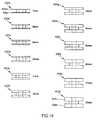
- FIGS. 1 a-cillustrates a first embodiment of an intervertebral trial spacer of the invention is illustrated in side, top and side cutaway views, respectively.
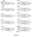
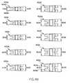
- FIG. 1 dillustrates a first set of intervertebral spacers of the invention in a side view.
- FIGS. 2 a-cillustrate a second embodiment of an intervertebral spacer of the invention in side, top and side cutaway views, respectively.
- FIG. 2 dillustrates a second set of intervertebral spacers of the invention in a side view.
- FIGS. 3 a-cillustrate a third embodiment of an intervertebral spacer of the invention in side, top and side cutaway views, respectively.
- FIG. 3 dillustrates a third set of tapered intervertebral spacers of the invention in a side view.
- FIGS. 4 a-cillustrate a fourth embodiment of an intervertebral spacer of the invention in side, top and side cutaway views, respectively.
- FIG. 4 dillustrates a fourth set of tapered intervertebral spacers of the invention in a side view.
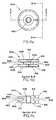
- FIG. 5 aillustrates a first embodiment of a spacer insertion tool 500 of the invention in a side view.
- FIG. 5 bis a cutaway view of the insertion tool of FIG. 5 a holding the spacer of FIGS. 1 a-c.
- FIG. 6 a-billustrates an embodiment of a loading accessory for a spacer insertion tool of the invention in side and top views, respectively.
- FIG. 6cshows the loading accessory of FIGS. 6 a-b in operation to load the spacer of FIG. 1 a-c into the spacer insertion tool of FIG. 5 a.
- FIG. 6 dshows the loading accessory of FIGS. 6 a-b in operation to unload the spacer the spacer insertion tool of FIG. 5 a.
- FIG. 7 aillustrates another embodiment of a spacer insertion tool of the invention in a side view.
- FIG. 7 bis a cutaway view of the insertion tool of FIG. 7 a holding the spacer of FIGS. 4 a-c.
- FIGS. 8 a-billustrates yet another embodiment of a spacer insertion tool of the invention in open and closed side views, respectively.
- FIG. 8 cis a cutaway view of the insertion tool of FIGS. 8 a-b holding the spacer of FIGS. 4 a-c.
- the patient spineis exposed through an anterior approach (i.e. the surgeon creates an access hole which permits direct interaction with the anterior and/or anterio-lateral portion of the intervertebral bodies).
- the surgeonremoves the intervertebral disc material, usually leaving some portion of the annulus (the cylindrical weave of fibrous tissue which normally surrounds and constrains the softer cartilage cushion of the disc material).
- the surgeonthen, in succession, inserts a series of intervertebral trial spacers of defined width.
- Each of the series of spacersis of a progressively wider thickness, resulting in the continual widening of the space until restoration of the proper disc height has been achieved.
- Proper disc height restorationis determined by surgical experience, and by observation of the annulus. (Often, the tightening of the annulus indicates that the proper disc height has been reached, inasmuch as the annulus is much less likely to be distorted by the same disruption that caused the intervertebral disc to collapse in the first place.)
- Each trial spaceris a generally cylindrical disc having a deep annular groove at its midpoint, which forms a central trunk and radial flanges at each end of the trunk. Stated alternatively, two cylindrical upper and lower halves of the disc are held in a closely coaxial spaced apart association by the central trunk, which forms a coaxial bridge between the upper and lower halves.
- the annular grooveis particularly useful for holding the spacer using the spacer insertion instrument of the invention, described below, in that the holding end of the insertion instrument fits within the groove.
- embodiments of the trial spacer elementsare disclosed.
- support portionsthe portions that are in contact with the adjacent vertebral bodies when the spacer is disposed between the bodies
- spacers having this featureare generally described herein as “constant thickness” trial spacers.
- the support portionsare not parallel, providing an overall taper to the spacer at an angle. Spacers having this feature are generally described herein as “tapered thickness” trial spacers. The tapered thickness trial spacers are particularly useful for treating scoliosis, as described below.
- embodiments of the trial spacer elementsinclude beveled flanges and non-parallel annular groove walls. More specifically, in some embodiments, such as the second and fourth embodiments described below, the flanges are radially beveled in that an outer edge of the top surface of the disc is tapered toward an outer edge of the bottom surface of the disc. In other embodiments, such as the first and third embodiment described below, the flanges are not radially beveled in this manner.
- the radial beveling featurecan be particularly useful for easing the insertion of the spacer in between collapsed vertebral bodies, as described below.
- the walls of the annular grooveare parallel, such that the floor of the groove is as wide as the opening of the groove.
- the walls of the annular grooveare tapered toward one another with the increasing depth of the groove, such that the floor of the groove is narrower than the opening of the groove.
- each spacer in a particular setmaintains the same diameter as the other spacers in the set. (It shall be understood that different collections of spacers may be provided such that the diameter of the selected collection of trial spacers is appropriate for the specific patient being treated. For example, the diameters of the trial spacers in a collection that is suitable for use with pediatric patients would be smaller than the diameters of the trial spacers in a collection that is suitable for use with adult patients.) Also preferably, each spacer in a particular set has a predetermined depth that differs from the depth of the other spacers in the set.
- the predetermined depthis provided in that while each spacer in the set shares the same annular groove dimensions (so that each can be held by the same insertion instrument), each spacer has a different flange thickness (in sets where the spacers are constant thickness spacers).
- the predetermined maximum depth and predetermined minimum depthare provided in that while each spacer in the set shares the same annular groove dimensions (so that each can be held by the same insertion instrument), each spacer has a different maximum flange thickness and a different minimum flange thickness.
- the overall taper angleis the same for each spacer in the set. The usefulness of providing sets of spacers similar in most respects except for the depth dimension will be described in greater detail below.
- FIGS. 1 a-ca first embodiment of an intervertebral trial spacer 100 of the invention is illustrated in side, top and side cutaway views, respectively.
- the spacer 100is a cylindrical disc with an annular groove 102 that forms a central trunk 103 and radial flanges 104 , 106 at each end of the trunk 102 .
- support portions 108 , 110 of the top and bottom surfaces 112 , 114 of the discare parallel.
- the walls 120 , 122 of the annular groove 102are parallel, such that the floor 124 of the groove 102 is as wide as the opening 126 of the groove 102 .
- the spacer 100has a central bore 128 .
- each spacer 100 a-lis formed generally similarly to the intervertebral spacer 100 of FIGS. 1 a-c , except that each spacer 100 a-I has a predetermined depth (denoted by the preferred dimension identified adjacent each spacer) provided in that while each spacer 1 a-l shares the same annular groove dimensions as the other spacers, each spacer 200 a- l has a different flange thickness dimension.
- the flanges 104 l , 106 lare thicker than the flanges 104 a , 106 a.
- FIGS. 2 a-ca second embodiment of an intervertebral spacer 200 of the invention is illustrated in side, top and side cutaway views, respectively.
- the spacer 200is a cylindrical disc with an annular groove 202 that forms a central trunk 203 and radial flanges 204 , 206 at each end of the trunk 202 .
- the flanges 204 , 206are radially tapered in that support portions 208 , 210 of the top and bottom surfaces 212 , 214 of the disc are parallel, while an outer edge 216 of the top surface 212 is tapered toward an outer edge 218 of the bottom surface 214 .
- the walls 220 , 222 of the annular groove 202are tapered toward one another with the increasing depth of the groove 202 , such that the floor 224 of the groove 202 is more narrow than the opening 226 of the groove.
- the spacer 200has a central bore 228 .
- each spacer 200 a-lis formed generally similarly to the intervertebral spacer 200 of FIGS. 2 a-c , except that each spacer 200 a-l has a predetermined depth (denoted by the preferred dimension identified adjacent each spacer) provided in that while each spacer 2 a-l shares the same annular groove dimensions as the other spacers, each spacer 200 a-l has a different flange thickness dimension.
- the flanges 204 l , 206 lare thicker than the flanges 204 a , 206 a.
- a first embodiment (particularly useful for inserting constant thickness trial spacers) of a spacer insertion toolincludes an elongated shaft and a handle at one end of the shaft.
- the distal end of the shaftincludes semi-circular hook that is adapted to hold a trial spacer within an enclosure formed by the hook.
- the angle swept out by the hookis slightly greater than 180 degrees, but the inner diameter of the hook is only slightly larger than the central trunk of the trial spacer. Therefore, the trial spacer may be snapped into the enclosure, but maintains complete rotational freedom within its grasp.
- a loading toolmay be provided to assist in the loading and unloading of the trial spacer from the trial spacer insertion instrument of this embodiment.
- This loading toolcomprises a forked hook having two tines separated by a notch that engages the shaft of the insertion tool as the tines engage the flanges of the trial spacer, to force the trial spacer into the enclosure.
- the same devicemay be utilized to remove the spacer from the enclosure, by reversing the position of the forked hook relative to the insertion tool and the spacer.
- the insertion tool 500includes an elongated shaft 502 and a handle 503 at one end of the shaft 502 .
- the insertion tool 5includes a semi-circular hook 504 that is adapted to hold an intervertebral spacer of the invention within an enclosure 506 of the hook 504 .
- the central trunk of the spacercan be snapped into the enclosure 506 of the hook 504 so that the extent of the hook 504 fits loosely within the annular groove of the spacer and is flanked by the flanges of the spacer.
- the central trunk of the spacercan also be snapped out of the enclosure 506 .
- the hook 504has an opening 508 that temporarily expands when the central trunk of the spacer is forced through the opening 508 . That is, the outer diameter of the central trunk is greater than the width of the opening 508 , so that the central trunk cannot pass through the opening 508 without force.
- the application of a force sufficient to cause the opening 508 to expand when confronted with the central trunkcauses the central trunk to pass through the opening 508 .
- the opening 508will contract.
- the temporary expansion in this embodimentis provided by the hook 504 being formed of a material having a low elasticity and the hook 504 being provided with a stress notch 510 on the extent (preferably located opposite the opening 508 for maximum efficiency) to ease the expansion.
- the opening 508prevents the central trunk from exiting the enclosure radially through the opening, because, as stated above, the outer diameter of the central trunk is greater than the width of the opening 508 . Further, by flanking the extent of the hook 504 , the flanges of the spacer prevent the spacer from exiting the enclosure laterally. The hook 504 therefore holds the spacer loosely in the enclosure so that the spacer can rotate about the cylindrical axis of the central trunk while being held by the hook 504 .
- FIG. 5 ba cutaway view of the insertion tool 500 of FIG. 5 a holding the spacer 100 of FIGS. 1 a-c shows the extent of the hook 504 in cross-section and fitting within the annular groove of the spacer.
- the width of the extentis smaller than the width of the annular groove, and the depth of the extent is less than the depth of the annular groove if it is desirable for the flanges to fully flank the extent.
- the outer diameter of the hook 504is substantially equal to the outer diameter of the spacer 100 .
- FIG. 6 a-ban embodiment of a loading accessory 600 for a spacer insertion tool of the invention is illustrated in side and top views, respectively.
- the loading accessory 600can be used to ease the passing of the central trunk of the spacer through the opening of the spacer insertion tool, both for loading the spacer into the enclosure and unloading the spacer from the enclosure.
- the loading accessory 600includes an elongated shaft 602 and a forked hook 604 at an end of the shaft 602 .
- a notch 606 having a base 608separates the tines 610 , 612 of the forked hook 604 .
- the width of the notch 608 separating the tines 610 , 612is wide enough to accommodate the width of the hook 504 of the insertion tool 500 and the width of the shaft 502 of the insertion tool 500 , but narrow enough so that the tines 610 , 612 can engage the edges of the flanges of the spacer.
- the curvature of the tines 608 , 610follows the curvature of the edges of the flanges.
- the loading accessory 600 of FIGS. 6 a-bis shown in operation to load the spacer 100 of FIG. 1 a-c into the spacer insertion tool 500 of FIG. 5 a .
- the spacer 100is positioned adjacent the opening 508 of the insertion tool 500 .
- the tines 610 , 612 of the loading accessory 600are passed on either side of the shaft 502 of the insertion tool 500 such that the notch 606 accommodates the shaft 502 and until the base 608 of the notch 606 contacts the shaft 502 .
- the loading accessory 600is rotated, using the contact between the shaft 502 and the base 608 as a fulcrum, to cause the tines 610 , 612 to engage the flanges 104 , 106 of the spacer 100 and push them into the enclosure 506 of the tool 500 .
- the loading accessory 600 of FIGS. 6 a-bis shown in operation to unload the spacer 100 of FIG. 1 a-c from the spacer insertion tool 500 of FIG. 5 a .
- the tines 610 , 612 of the loading accessory 600are passed on either side of the shaft 502 of the insertion tool 500 such that the notch 606 accommodates the shaft 502 and until the base 608 of the notch 606 contacts the shaft 502 .
- the loading accessory 600is rotated, using the contact between the shaft 502 and the base 608 as a fulcrum, to cause the tines 610 , 612 to engage the flanges 104 , 106 of the spacer 100 and push them out of the enclosure 506 of the tool 500 .
- the width of the notch 606accommodates the width of the hook 504 as the spacer 100 is being pushed out of the enclosure 506 .
- the insertion tool of this first embodimentcan be used to insert a series of constant thickness trial spacers (some of which may have beveled flange edges for easing the insertion between the collapsed bones and into the space to be distracted). More specifically, thinner trial spacers can initially be inserted into the spacer, followed successively by thicker trial spacers until the desired spacing is achieved. Once the appropriate spacing has been achieved, immobilization of the spine by fixation, fusion, or non-fusion techniques and devices, such as those set forth in co-pending U.S. patent application Ser. Nos.
- each of the tapered trial spacershas an overall wedge shape that generally corresponds to the pathological tapering of the adjacent bones that characterizes scoliosis.
- the overall disc alignmentmay be compensated, restoring appropriate anatomical status. It should be understood that additional rotation of the spacer may restore lordosis to the spine, and that over-rotation (if the particular spine is flexible enough) of the spacer would result in a pathological curvature in the opposite direction.
- FIGS. 3 a-ca third embodiment of an intervertebral spacer 300 of the invention is illustrated in side, top and side cutaway views, respectively.
- the spacer 300is a cylindrical disc with an annular groove 302 that forms a central trunk 303 and radial flanges 304 , 306 at each end of the trunk 303 .
- support portions 308 , 310 of the top and bottom surfaces 312 , 314 of the discare not parallel, providing an overall taper to the spacer 300 at an angle.
- the walls 320 , 322 of the annular groove 302are parallel, such that the floor 324 of the groove 302 is as wide as the opening 326 of the groove 302 .
- the spacer 300has a central bore 328 .
- each spacer 300 a-jis formed generally similarly to the intervertebral spacer 300 of FIGS. 3 a-c , except that each spacer 300 a-j has a predetermined maximum depth (denoted by the preferred maximum depth dimension identified adjacent each spacer) and a predetermined minimum depth (denoted by the preferred minimum depth dimension identified adjacent each spacer), each provided in that while each spacer 300 a-j shares the same annular groove width dimension as the other spacers, each spacer 300 a-j has a different maximum flange thickness dimension and a different minimum flange thickness dimension.
- the flanges 304 j , 306 jhave a thicker maximum flange thickness dimension and a thicker minimum flange thickness dimension than the flanges 304 a , 304 a.
- FIGS. 4 a-ca fourth embodiment of an intervertebral spacer 400 of the invention is illustrated in side, top and side cutaway views, respectively.
- the spacer 400is a cylindrical disc with an annular groove 402 that forms a central trunk 403 and radial flanges 404 , 406 at each end of the trunk 403 .
- support portions 408 , 410 of the top and bottom surfaces 412 , 414 of the discare not parallel.
- the flanges 404 , 406are radially tapered in that an outer edge 416 of the top surface 412 is tapered toward an outer edge 418 of the bottom surface 414 .
- the walls 420 , 422 of the annular groove 402are tapered toward one another with the increasing depth of the groove 402 , such that the floor 424 of the groove 402 is more narrow than the opening 426 of the groove.
- the spacer 400has a central bore 428 .
- each spacer 4 a-jis formed generally similarly to the intervertebral spacer 400 of FIGS. 4 a-c , except that each spacer 4 a-j has a predetermined maximum depth (denoted by the preferred maximum depth dimension identified adjacent each spacer) and a predetermined minimum depth (denoted by the preferred minimum depth dimension identified adjacent each spacer), each provided in that while each spacer 4 a-j shares the same annular groove width dimension as the other spacers, each spacer 4 a-j has a different maximum flange thickness dimension and a different minimum flange thickness dimension.
- the flanges 404 j , 406 jhave a thicker maximum flange thickness dimension and a thicker minimum flange thickness dimension than the flanges 404 a , 406 a.
- the walls of the annular grooveare parallel. In other embodiments, they are not parallel. In some embodiments where they are not parallel, they are tapered toward one another with the increasing depth of the groove. In other embodiments where they are not parallel, they are tapered toward one another with the decreasing depth of the groove. In some embodiments, the support portions of the top and bottom surfaces are parallel. In other embodiments, they are not parallel.
- the flangesare radially tapered in that the outer edge of the top surface is tapered toward an outer edge of the bottom surface. In other embodiments, the flanges are not radially tapered. In some embodiments, the spacer has a central bore. In other embodiments, the spacer does not have a central bore.
- the inventionencompasses a set of spacers in which the angle of the overall taper of each spacer in the set is different than the angle of the overall taper of at least one other spacer in the set.
- the angle of the overall tapercan be predetermined, such that the maximum flange thickness and the minimum flange thickness can be selected to achieve a desired overall taper angle.
- the spacersare shown as having a cylindrical shape, it should be understood that in other embodiment, the spacers can have oval, square, or rectangular cross-sections, or cross-sections of other shapes, provided that any comers are rounded as necessary to prevent damage to surrounding tissue.
- This second embodiment of the spacer insertion toolincludes a handle and an elongated dual shaft, the dual shaft culminating in a trial spacer grasping pincer, rather than the simple hook of the first embodiment.
- This pincerdiffers from the hook of the first embodiment of the trial spacer insertion tool described above, inasmuch as the dual shaft includes a fixed shaft and a selectively engagable shaft which, together, form pincer. More specifically, the fixed shaft includes a semicircular hook portion of the pincer at its distal end, having an enclosure within which a trial spacer can be placed.
- the selectively engagable shaftincludes the complementary portion of the pincer, which moves toward the hook portion to grasp and hold the trial spacer when the engagable shaft is engaged, and moves away from the hook portion to release the trial spacer when the engagable shaft is disengaged.
- the spacercan be unloaded and loaded when the engagable shaft is disengaged.
- the engagement actionprevents the spacer from moving relative to the tool, and therefore permits the surgeon to rotate the tapered spacer in between the vertebral bodies (by contrast, the first embodiment of the trial spacer insertion instrument permitted the spacer to rotate freely in the enclosure of the hook).
- the insertion tool 700includes an elongated shaft 702 and a handle 704 at one end of the shaft 702 .
- the insertion tool 700further includes a compression assembly that is adapted to hold an intervertebral spacer of the invention at the other end of the shaft 702 so that the spacer cannot move when held.
- the insertion tool 700further includes a release assembly that is adapted to release the spacer from being held.
- the compression assemblyincludes a semicircular hook 706 at the other end of the shaft 702 and a compression surface 708 adjacent the hook 706 .
- the hook 706has an enclosure 709 defined by the extent of the hook 706 and an opening 710 through which the central trunk can pass freely to be placed into the enclosure 709 . That is, the width of the opening 710 is greater than the diameter of the central trunk. When the central trunk is placed within the enclosure 709 , the extent of the hook 706 fits loosely within the annular groove of the spacer.
- the compression assemblyfurther includes a compression trigger 712 mechanically connected to the hook 706 such that as the compression trigger 712 is placed in an engaged position, the hook 706 is pulled toward the compression surface 708 .
- the mechanical connectionincludes a rod 714 connected at one end to the hook 706 and at the other end to a plate 716 .
- a rod 718 protruding from the plate 716is engaged by a slot 720 in a lever 722 attached to the compression trigger 712 .
- the rod 714 of the lever 722pulls the plate 716 by the slot 720 .
- the plate 716in turn pulls the rod 714 , which in turn pulls the hook 704 toward the compression surface 708 .
- the release assemblyincludes a spring 724 biasing the compression trigger 712 to a disengaged position. Therefore, after the compression trigger 712 is released, it moves to the disengaged position. However, so that the central trunk remains compressed within the enclosure even after the compression trigger 712 is released (e.g., so that the surgeon does not need to continue holding the compression trigger 712 to effect the compression), the compression assembly further includes teeth 726 on the rod 714 and corresponding teeth 730 that confront the rod teeth 726 to prevent the rod 714 from retreating, to maintain the compression.
- the release assemblyfurther includes a release trigger 732 that can be engaged to release the rod teeth 726 from the corresponding teeth 730 to allow the rod 714 to return to its rest position, thereby alleviating the compression.
- the release trigger 732has the corresponding teeth 730 and the release assembly further includes a spring 734 that biases the release trigger 732 toward a position in which the corresponding teeth 730 engage the rod teeth 726 .
- This arrangementallows the release trigger 732 to be engaged by pressing the release trigger 732 with a force great enough to overcome the bias of the spring 734 , so that the corresponding teeth 730 are disengaged from the rod teeth 726 . Therefore, when the release trigger 732 is pressed, the compression is alleviated, and the central trunk of the spacer can be freely passed through the opening 710 to be taken out of the enclosure 709 .
- FIG. 7ba cutaway view of the insertion tool 700 of FIG. 7 a holding the spacer 400 of FIGS. 4 a-c shows the extent of the hook 706 in cross-section and fitting within the annular groove of the spacer as the spacer is compressed between the compression surface 708 and the hook 706 .
- the width of the extent of the hook 706is smaller than the width of the annular groove, and the depth of the extent is less than the depth of the annular groove if it is desirable for the flanges to fully flank the extent.
- the outer diameter of the hook 706is substantially equal to the outer diameter of the spacer 400 .
- FIGS. 8 a-byet another embodiment of a spacer insertion tool 800 of the invention is illustrated in open and closed side views, respectively.
- the insertion tool 800includes an elongated shaft 802 and a handle 804 at one end of the shaft 802 .
- the insertion tool 800further includes a compression assembly that is adapted to hold an intervertebral spacer of the invention at the other end of the shaft 802 so that the spacer cannot move when held.
- the insertion tool 800further includes a release assembly that is adapted to release the spacer from being held.
- the compression assemblyincludes a claw 806 at the other end of the shaft 802 having opposing pincers 807 a , 807 b , each providing one of opposing compression surfaces 808 a , 808 b .
- the claw 806has an enclosure 809 defined by the extents of the pincers 807 a , 807 b and an opening 810 through which the central trunk can pass freely to be placed into the enclosure 809 when the claw 806 is open (i.e., when the opposing pincers 807 a , 807 b are separated). That is, the width of the opening 810 is greater than the diameter of the central trunk when the claw 806 is open.
- the extents of the pincers 807 a , 807 bfit loosely within the annular groove of the spacer.
- the compression assemblyfurther includes a compression slide 812 that when moved to an engaged position (here, a forward position shown in FIG. 8 b ) closes the claw 806 .
- the closure of the claw 806 by the compression slide 812is effected as follows.
- One of the pincers 807 ais in a fixed position relative to the elongated shaft 802 whereas the other pincer 807 b is adapted to rotate about an axis transverse to the shaft 802 .
- the rotationis provided by a pin 813 passing through each pincer at a rotation point along the transverse axis.
- One position of the movable pincer 807 b along the rotation pathshown in FIG.
- the engagement surface 814is tapered so that when the compression slide 812 is moved to the engaged, the engagement surface 816 of the compression slide 812 moves along the available compression path and engages the tapered surface 814 to push the surface 814 aside and thereby cause a rotation of the movable pincer 807 b to the position defining the closed claw 806 .
- the release assemblyincludes a spring 818 biasing the movable pincer 807 b to the rotation path position defining the open claw 806 . Therefore, when the compression slide 812 is moved to a disengaged position (here, a backward position), the engagement surface 816 of the compression slide 812 moves along an available release path (here, a backtracking along the compression path) and frees the engagement surface 814 of the movable pincer 807 b to allow the engagement surface 814 to return to a place in the available compression path by the biasing action of the spring 818 .
- the claw 806is open, the compression is alleviated and the central trunk of the spacer can be freely passed through the opening 810 to be taken out of the enclosure 809 .
- the release assemblyfurther includes at least one barrier 820 a , 820 b that limits the biasing action of the spring 818 by preventing the movable pincer 807 b from rotating beyond the position that places the engagement surface 814 in the available compression path.
- confrontation surfaces 822 a , 822 b on the movable pincer 807 bconfront the barriers 820 a , 820 b as the pincer 807 b rotates toward the rotation path position defining the open claw 806 under the biasing force of the spring 818 .
- the barriers 820 a , 820 bprevent the confrontation surfaces 822 a , 822 b from advancing further.
- the spring 818 and the barriers 820 a , 820 bmaintain the movable pincer 807 b in this position until the compression slide 812 is advanced toward the engaged position by a force great enough to overcome the biasing force of the spring 818 .
- FIG. 8 ca cutaway view of the insertion tool 800 of FIGS. 8 a-b holding the spacer 400 of FIGS. 4 a-c shows the extents of the pincers 807 a , 807 b in cross-section and fitting within the annular groove of the spacer as the spacer is compressed between the compression surfaces 808 a , 808 b .
- the width of each extentis smaller than the width of the annular groove, and the depth of each extent is less than the depth of the annular groove if it is desirable for the flanges to fully flank the extents.
- the outer diameter of the claw 806is substantially equal to the outer diameter of the spacer 400 .
- the tapered trial spacersthemselves can include angle markers that clearly indicate to the surgeon the amount of rotation that was necessary for the correction of the spinal deformity. Such angle markers can also serve as a guide for the implantation of a secondary bone graft (e.g., a femoral ring) or another intervertebral spacer device.
- a secondary bone grafte.g., a femoral ring
- the trial spacersmay be left in the patient while rod fixation apparatuses (anterior or posterior) are mounted to the spine, thereby holding the spine in its desired orientation even after the trial spacers are subsequently removed.
- rod fixation apparatusesanterior or posterior
- surface plating and/or intervertebral cage devicesmay be mounted to the spine to promote fusion without the need for bulky rod assemblies. (although this approach may seem more surgically desirable, questions regarding the long-term stability of these constructs have led to some surgeons to choose combinations of rodding and cages.)
- a third approach to immobilizing the corrected spineis to insert a shaped bone graft, or suitably contoured porous metal spacer, into the properly distracted intervertebral space, and either plating or using rod fixation to hold the construct stable as the spine fuses.
- the insertion of a femoral ring allograft, or porous metal implant, into an intervertebral spaceis described more fully in co-pending U.S. patent application Ser. Nos. 09/844,904, and 09/906,123, entitled “A Porous Interbody Fusion Device Having Integrated Polyaxial Locking Interference Screws”, and “Porous Intervertebral Distraction Spacers”, assigned to the same assignee as the present invention, the specifications of each being incorporated herein by reference.
- the tapered trial spacersmay also serve as precursors (measuring instruments) for another spacer (e.g., a porous metal spacer), similarly shaped, which is inserted into the intervertebral space by the same instrument.
- another spacere.g., a porous metal spacer
Landscapes
- Health & Medical Sciences (AREA)
- Engineering & Computer Science (AREA)
- Orthopedic Medicine & Surgery (AREA)
- Biomedical Technology (AREA)
- Transplantation (AREA)
- Heart & Thoracic Surgery (AREA)
- Oral & Maxillofacial Surgery (AREA)
- Cardiology (AREA)
- Vascular Medicine (AREA)
- Life Sciences & Earth Sciences (AREA)
- Animal Behavior & Ethology (AREA)
- General Health & Medical Sciences (AREA)
- Public Health (AREA)
- Veterinary Medicine (AREA)
- Neurology (AREA)
- Physical Education & Sports Medicine (AREA)
- Prostheses (AREA)
Abstract
Description
Claims (12)
Priority Applications (2)
| Application Number | Priority Date | Filing Date | Title |
|---|---|---|---|
| US09/906,121US6478801B1 (en) | 2001-07-16 | 2001-07-16 | Insertion tool for use with tapered trial intervertebral distraction spacers |
| US10/223,147US6976988B2 (en) | 2001-07-16 | 2002-08-19 | Insertion tool for use with tapered trial intervertebral distraction spacers |
Applications Claiming Priority (1)
| Application Number | Priority Date | Filing Date | Title |
|---|---|---|---|
| US09/906,121US6478801B1 (en) | 2001-07-16 | 2001-07-16 | Insertion tool for use with tapered trial intervertebral distraction spacers |
Related Child Applications (1)
| Application Number | Title | Priority Date | Filing Date |
|---|---|---|---|
| US10/223,147ContinuationUS6976988B2 (en) | 2001-07-16 | 2002-08-19 | Insertion tool for use with tapered trial intervertebral distraction spacers |
Publications (1)
| Publication Number | Publication Date |
|---|---|
| US6478801B1true US6478801B1 (en) | 2002-11-12 |
Family
ID=25421971
Family Applications (2)
| Application Number | Title | Priority Date | Filing Date |
|---|---|---|---|
| US09/906,121Expired - LifetimeUS6478801B1 (en) | 2001-07-16 | 2001-07-16 | Insertion tool for use with tapered trial intervertebral distraction spacers |
| US10/223,147Expired - Fee RelatedUS6976988B2 (en) | 2001-07-16 | 2002-08-19 | Insertion tool for use with tapered trial intervertebral distraction spacers |
Family Applications After (1)
| Application Number | Title | Priority Date | Filing Date |
|---|---|---|---|
| US10/223,147Expired - Fee RelatedUS6976988B2 (en) | 2001-07-16 | 2002-08-19 | Insertion tool for use with tapered trial intervertebral distraction spacers |
Country Status (1)
| Country | Link |
|---|---|
| US (2) | US6478801B1 (en) |
Cited By (161)
| Publication number | Priority date | Publication date | Assignee | Title |
|---|---|---|---|---|
| US20030014057A1 (en)* | 2001-07-16 | 2003-01-16 | Ralph James D. | Insertion tool for use with trial intervertebral distraction spacers |
| US20030023245A1 (en)* | 2001-07-16 | 2003-01-30 | Ralph James D. | Insertion tool for use with tapered trial intervertebral distraction spacers |
| US20030225456A1 (en)* | 2000-05-01 | 2003-12-04 | Ek Steven W. | System and method for joint resurface repair |
| US6663636B1 (en)* | 2002-03-12 | 2003-12-16 | United Orthopedic Corporation | Femur rasp fastener |
| US6679917B2 (en) | 2000-05-01 | 2004-01-20 | Arthrosurface, Incorporated | System and method for joint resurface repair |
| WO2003051210A3 (en)* | 2000-05-01 | 2004-03-25 | Arthrosurface Inc | System and method for joint resurface repair |
| US20040093089A1 (en)* | 2001-07-16 | 2004-05-13 | Ralph James D. | Porous intervertebral distraction spacers |
| US20040148030A1 (en)* | 2000-05-01 | 2004-07-29 | Ek Steven W. | System and method for joint resurface repair |
| US20040158326A1 (en)* | 2001-07-16 | 2004-08-12 | Ralph James D. | Instruments for reorienting vertebral bones for the treatment of scoliosis |
| US20040167535A1 (en)* | 2001-07-16 | 2004-08-26 | Errico Joseph P. | Instrumentation for manipulating artificial interverterbral disc trials having a cylindrical engagement surface |
| US20040167628A1 (en)* | 2002-10-21 | 2004-08-26 | Foley Kevin T. | Systems and techniques for restoring and maintaining intervertebral anatomy |
| US6805716B2 (en)* | 2001-07-16 | 2004-10-19 | Spine Core, Inc. | Orthopedic device set for reorienting vertebral bones for the treatment of scoliosis |
| US20040236370A1 (en)* | 2001-07-16 | 2004-11-25 | Ralph James D. | Insertion tool for use with intervertebral spacers |
| US20040236342A1 (en)* | 2002-04-23 | 2004-11-25 | Ferree Bret A. | Device to assess ADR motion |
| US20050192570A1 (en)* | 2004-02-27 | 2005-09-01 | Jackson Roger P. | Orthopedic implant rod reduction tool set and method |
| US20050192579A1 (en)* | 2004-02-27 | 2005-09-01 | Jackson Roger P. | Orthopedic implant rod reduction tool set and method |
| US6989032B2 (en) | 2001-07-16 | 2006-01-24 | Spinecore, Inc. | Artificial intervertebral disc |
| US20060020342A1 (en)* | 2004-07-21 | 2006-01-26 | Ferree Bret A | Facet-preserving artificial disc replacements |
| US20060025778A1 (en)* | 2004-07-21 | 2006-02-02 | Ferree Bret A | Methods and apparatus for artificial disc replacement (ADR) insertion and other surgical procedures |
| US20060069391A1 (en)* | 2004-02-27 | 2006-03-30 | Jackson Roger P | Spinal fixation tool attachment structure |
| US20060074418A1 (en)* | 2004-09-24 | 2006-04-06 | Jackson Roger P | Spinal fixation tool set and method for rod reduction and fastener insertion |
| US7029479B2 (en) | 2000-05-01 | 2006-04-18 | Arthrosurface, Inc. | System and method for joint resurface repair |
| EP1647244A1 (en)* | 2004-10-15 | 2006-04-19 | Zimmer GmbH | System of instruments for the insertion of intervertebral disc implants |
| US20060089651A1 (en)* | 2004-10-26 | 2006-04-27 | Trudeau Jeffrey L | Apparatus and method for anchoring a surgical rod |
| US20060111713A1 (en)* | 2004-11-23 | 2006-05-25 | Jackson Roger P | Spinal fixation tool set and method |
| US20060193326A1 (en)* | 2000-05-17 | 2006-08-31 | Juniper Networks, Inc. | Dual aal1 device and synchronization method used therewith |
| US20060217806A1 (en)* | 2005-03-28 | 2006-09-28 | Peterman Marc M | Spinal system and method including lateral approach |
| US20060217807A1 (en)* | 2005-03-28 | 2006-09-28 | Peterman Marc M | Spinal device including lateral approach |
| US7118599B2 (en) | 2001-07-16 | 2006-10-10 | Spinecore, Inc. | Artificial intervertebral disc |
| US20060235426A1 (en)* | 2005-04-15 | 2006-10-19 | Sdgi Holdings, Inc. | Instruments, implants and methods for positioning implants into a spinal disc space |
| US7125425B2 (en) | 2002-10-21 | 2006-10-24 | Sdgi Holdings, Inc. | Systems and techniques for restoring and maintaining intervertebral anatomy |
| US20060247778A1 (en)* | 2005-01-26 | 2006-11-02 | Ferree Bret A | Intradiscal devices including spacers facilitating posterior-lateral and other insertion approaches |
| US20060264968A1 (en)* | 1999-10-21 | 2006-11-23 | George Frey | Devices and techniques for a posterior lateral disc space approach |
| US20060293680A1 (en)* | 2004-02-27 | 2006-12-28 | Jackson Roger P | Orthopedic implant rod reduction tool set and method |
| US7160327B2 (en) | 2001-07-16 | 2007-01-09 | Spinecore, Inc. | Axially compressible artificial intervertebral disc having limited rotation using a captured ball and socket joint with a solid ball and compression locking post |
| US20070032162A1 (en)* | 2004-11-23 | 2007-02-08 | Jackson Roger P | Spinal fixation tool set and method |
| US20070093898A1 (en)* | 2005-09-26 | 2007-04-26 | Schwab Frank J | Transforaminal hybrid implant |
| WO2006033067A3 (en)* | 2004-09-23 | 2007-05-18 | Spine Solutions Inc | System and method for an intervertebral implant |
| US7235081B2 (en) | 2001-07-16 | 2007-06-26 | Spinecore, Inc. | Wedge plate inserter/impactor and related methods for use in implanting an artificial intervertebral disc |
| US20070213737A1 (en)* | 2006-03-08 | 2007-09-13 | Seaspine, Inc. | Insertion tool for an intervertebral spacer providing multiple angles of insertion |
| US20070213826A1 (en)* | 2006-03-08 | 2007-09-13 | Seaspine, Inc. | Intervertebral spacer and insertion tool providing multiple angles of insertion |
| US20080027544A1 (en)* | 2006-07-28 | 2008-01-31 | Warsaw Orthopedic Inc. | Instruments and techniques for engaging spinal implants for insertion into a spinal space |
| US20080039860A1 (en)* | 2006-08-10 | 2008-02-14 | Pioneer Laboratories, Inc. | Insertion Instrument for Artificial Discs |
| US20080077153A1 (en)* | 2006-09-22 | 2008-03-27 | Pioneer Surgical Technology, Inc. | System and methods for inserting a spinal disc device into an intervertebral space |
| US20080082172A1 (en)* | 2006-09-29 | 2008-04-03 | Jackson Roger P | Interspinous process spacer |
| US20080097454A1 (en)* | 2006-09-19 | 2008-04-24 | Warsaw Orthopedic Inc. | Instruments and methods for spinal implant revision |
| US20080109005A1 (en)* | 2006-08-10 | 2008-05-08 | Trudeau Jeffrey L | System and Methods for Inserting a Spinal Disc Device Into an Intervertebral Space |
| US7393361B2 (en) | 2004-02-20 | 2008-07-01 | Spinecore, Inc. | Artificial intervertebral disc having a bored semispherical bearing with a compression locking post and retaining caps |
| US7468076B2 (en) | 2004-02-20 | 2008-12-23 | Spinecore, Inc. | Artificial intervertebral disc having a universal joint |
| US7510558B2 (en) | 2000-05-01 | 2009-03-31 | Arthrosurface, Inc. | System and method for joint resurface repair |
| US7544208B1 (en) | 2004-05-03 | 2009-06-09 | Theken Spine, Llc | Adjustable corpectomy apparatus |
| US7563286B2 (en) | 2002-08-15 | 2009-07-21 | Synthes Usa, Llc | Controlled artificial intervertebral disc implant |
| US7563284B2 (en) | 2002-08-15 | 2009-07-21 | Synthes Usa, Llc | Intervertebral disc implant |
| US20090216330A1 (en)* | 2004-09-23 | 2009-08-27 | Christophe Geisert | System and method for an intervertebral implant |
| US20090228054A1 (en)* | 2008-01-29 | 2009-09-10 | Jeffrey Hoffman | Rod Locking Instrument |
| US7713305B2 (en) | 2000-05-01 | 2010-05-11 | Arthrosurface, Inc. | Articular surface implant |
| US7713302B2 (en) | 2001-10-01 | 2010-05-11 | Spinecore, Inc. | Intervertebral spacer device utilizing a spirally slotted belleville washer having radially spaced concentric grooves |
| US7771477B2 (en) | 2001-10-01 | 2010-08-10 | Spinecore, Inc. | Intervertebral spacer device utilizing a belleville washer having radially spaced concentric grooves |
| US7799081B2 (en) | 2004-09-14 | 2010-09-21 | Aeolin, Llc | System and method for spinal fusion |
| US7803162B2 (en)* | 2003-07-21 | 2010-09-28 | Spine Solutions, Inc. | Instruments and method for inserting an intervertebral implant |
| US20100249797A1 (en)* | 2006-08-10 | 2010-09-30 | Trudeau Jeffrey L | Insertion Instrument for Artificial Discs |
| US7815648B2 (en) | 2004-06-02 | 2010-10-19 | Facet Solutions, Inc | Surgical measurement systems and methods |
| US7828853B2 (en) | 2004-11-22 | 2010-11-09 | Arthrosurface, Inc. | Articular surface implant and delivery system |
| US7862587B2 (en) | 2004-02-27 | 2011-01-04 | Jackson Roger P | Dynamic stabilization assemblies, tool set and method |
| US7896885B2 (en) | 2002-12-03 | 2011-03-01 | Arthrosurface Inc. | Retrograde delivery of resurfacing devices |
| US7896883B2 (en) | 2000-05-01 | 2011-03-01 | Arthrosurface, Inc. | Bone resurfacing system and method |
| US7901408B2 (en) | 2002-12-03 | 2011-03-08 | Arthrosurface, Inc. | System and method for retrograde procedure |
| US7914560B2 (en) | 2004-02-17 | 2011-03-29 | Gmedelaware 2 Llc | Spinal facet implant with spherical implant apposition surface and bone bed and methods of use |
| US7914545B2 (en) | 2002-12-03 | 2011-03-29 | Arthrosurface, Inc | System and method for retrograde procedure |
| US7918876B2 (en) | 2003-03-24 | 2011-04-05 | Theken Spine, Llc | Spinal implant adjustment device |
| US7951163B2 (en) | 2003-11-20 | 2011-05-31 | Arthrosurface, Inc. | Retrograde excision system and apparatus |
| US20110144469A1 (en)* | 2008-05-07 | 2011-06-16 | Patraicia Connolly | Bacterial/Cellular Recognition Impedance Algorithm |
| US20110202096A1 (en)* | 2010-02-12 | 2011-08-18 | John White | Spinal Rod and Screw Securing Apparatus and Method |
| US8029568B2 (en) | 2001-10-18 | 2011-10-04 | Spinecore, Inc. | Intervertebral spacer device having a slotted partial circular domed arch strip spring |
| US8066739B2 (en) | 2004-02-27 | 2011-11-29 | Jackson Roger P | Tool system for dynamic spinal implants |
| US8100972B1 (en) | 2007-07-02 | 2012-01-24 | Theken Spine, Llc | Spinal cage having deployable member |
| US8105368B2 (en) | 2005-09-30 | 2012-01-31 | Jackson Roger P | Dynamic stabilization connecting member with slitted core and outer sleeve |
| US8105381B2 (en) | 2002-12-13 | 2012-01-31 | Spine Solutions, Inc. | Intervertebral implant, insertion tool and method of inserting same |
| US8109979B2 (en) | 2003-03-06 | 2012-02-07 | Spinecore, Inc. | Instrumentation and methods for use in implanting a cervical disc replacement device |
| US8177841B2 (en) | 2000-05-01 | 2012-05-15 | Arthrosurface Inc. | System and method for joint resurface repair |
| US8206418B2 (en) | 2007-01-10 | 2012-06-26 | Gmedelaware 2 Llc | System and method for facet joint replacement with detachable coupler |
| US8267997B2 (en) | 2007-11-12 | 2012-09-18 | Theken Spine, Llc | Vertebral interbody compression implant |
| US8277507B2 (en) | 2002-04-12 | 2012-10-02 | Spinecore, Inc. | Spacerless artificial disc replacements |
| US8292958B1 (en) | 2007-07-02 | 2012-10-23 | Theken Spine, Llc | Spinal cage having deployable member |
| US8303601B2 (en) | 2006-06-07 | 2012-11-06 | Stryker Spine | Collet-activated distraction wedge inserter |
| US8308774B2 (en) | 2007-02-14 | 2012-11-13 | Pioneer Surgical Technology, Inc. | Spinal rod reducer and cap insertion apparatus |
| US8337500B2 (en) | 2006-07-31 | 2012-12-25 | Synthes Usa, Llc | Drilling/milling guide and keel cut preparation system |
| US8353932B2 (en) | 2005-09-30 | 2013-01-15 | Jackson Roger P | Polyaxial bone anchor assembly with one-piece closure, pressure insert and plastic elongate member |
| US8361159B2 (en) | 2002-12-03 | 2013-01-29 | Arthrosurface, Inc. | System for articular surface replacement |
| US8366745B2 (en) | 2007-05-01 | 2013-02-05 | Jackson Roger P | Dynamic stabilization assembly having pre-compressed spacers with differential displacements |
| US8388624B2 (en) | 2003-02-24 | 2013-03-05 | Arthrosurface Incorporated | Trochlear resurfacing system and method |
| US8394133B2 (en) | 2004-02-27 | 2013-03-12 | Roger P. Jackson | Dynamic fixation assemblies with inner core and outer coil-like member |
| US8409290B2 (en) | 2006-03-08 | 2013-04-02 | Seaspine, Inc. | Interbody device for spinal applications |
| US8425603B2 (en) | 2008-12-22 | 2013-04-23 | Synthes Usa, Llc | Orthopedic implant with flexible keel |
| US8470041B2 (en) | 2002-04-12 | 2013-06-25 | Spinecore, Inc. | Two-component artificial disc replacements |
| US8475498B2 (en) | 2007-01-18 | 2013-07-02 | Roger P. Jackson | Dynamic stabilization connecting member with cord connection |
| US8480745B2 (en) | 1997-08-26 | 2013-07-09 | Warsaw Orthopedic, Inc. | Spinal implant and cutting tool preparation accessory for mounting the implant |
| US8506634B2 (en) | 1999-07-02 | 2013-08-13 | DePuy Synthes Products, LLC | Intervertebral implant |
| US8523872B2 (en) | 2002-12-03 | 2013-09-03 | Arthrosurface Incorporated | Tibial resurfacing system |
| US8535326B2 (en) | 1999-09-14 | 2013-09-17 | DePuy Synthes Products, LLC | Insertion instrument for an intervertebral implant |
| US8545562B1 (en) | 2007-07-02 | 2013-10-01 | Theken Spine, Llc | Deployable member for use with an intervertebral cage |
| US8545538B2 (en) | 2005-12-19 | 2013-10-01 | M. Samy Abdou | Devices and methods for inter-vertebral orthopedic device placement |
| US8556938B2 (en) | 2009-06-15 | 2013-10-15 | Roger P. Jackson | Polyaxial bone anchor with non-pivotable retainer and pop-on shank, some with friction fit |
| US8591560B2 (en) | 2005-09-30 | 2013-11-26 | Roger P. Jackson | Dynamic stabilization connecting member with elastic core and outer sleeve |
| US8663229B2 (en) | 2003-04-28 | 2014-03-04 | DePuy Synthes Products, LLC | Instruments and method for preparing an intervertebral space for receiving an artificial disc implant |
| US8777994B2 (en) | 2004-06-02 | 2014-07-15 | Gmedelaware 2 Llc | System and method for multiple level facet joint arthroplasty and fusion |
| US8808380B2 (en) | 2007-08-27 | 2014-08-19 | William Casey Fox | Method and apparatus for an osteotomy fixation or arthrodesis cage |
| US8808294B2 (en) | 2008-09-09 | 2014-08-19 | William Casey Fox | Method and apparatus for a multiple transition temperature implant |
| US8864829B1 (en) | 2007-07-02 | 2014-10-21 | Theken Spine, Llc | Spinal cage having deployable member |
| US8979904B2 (en) | 2007-05-01 | 2015-03-17 | Roger P Jackson | Connecting member with tensioned cord, low profile rigid sleeve and spacer with torsion control |
| US8998990B2 (en) | 2006-07-24 | 2015-04-07 | DePuy Synthes Products, LLC | Intervertebral implant with keel |
| US9066716B2 (en) | 2011-03-30 | 2015-06-30 | Arthrosurface Incorporated | Suture coil and suture sheath for tissue repair |
| US9216041B2 (en) | 2009-06-15 | 2015-12-22 | Roger P. Jackson | Spinal connecting members with tensioned cords and rigid sleeves for engaging compression inserts |
| US9283076B2 (en) | 2009-04-17 | 2016-03-15 | Arthrosurface Incorporated | Glenoid resurfacing system and method |
| US9351852B2 (en) | 2002-05-23 | 2016-05-31 | Pioneer Surgical Technology, Inc. | Artificial disc device |
| US9358029B2 (en) | 2006-12-11 | 2016-06-07 | Arthrosurface Incorporated | Retrograde resection apparatus and method |
| US9439683B2 (en) | 2007-01-26 | 2016-09-13 | Roger P Jackson | Dynamic stabilization member with molded connection |
| US9451989B2 (en) | 2007-01-18 | 2016-09-27 | Roger P Jackson | Dynamic stabilization members with elastic and inelastic sections |
| US9456828B2 (en) | 2013-01-18 | 2016-10-04 | Symmetry Medical Manufacturing, Inc. | Medical instrument handle |
| US9468448B2 (en) | 2012-07-03 | 2016-10-18 | Arthrosurface Incorporated | System and method for joint resurfacing and repair |
| US9492200B2 (en) | 2013-04-16 | 2016-11-15 | Arthrosurface Incorporated | Suture system and method |
| US9662126B2 (en) | 2009-04-17 | 2017-05-30 | Arthrosurface Incorporated | Glenoid resurfacing system and method |
| US9668771B2 (en) | 2009-06-15 | 2017-06-06 | Roger P Jackson | Soft stabilization assemblies with off-set connector |
| US9743957B2 (en) | 2004-11-10 | 2017-08-29 | Roger P. Jackson | Polyaxial bone screw with shank articulation pressure insert and method |
| US9861492B2 (en) | 2014-03-07 | 2018-01-09 | Arthrosurface Incorporated | Anchor for an implant assembly |
| US10039578B2 (en) | 2003-12-16 | 2018-08-07 | DePuy Synthes Products, Inc. | Methods and devices for minimally invasive spinal fixation element placement |
| US20190015220A1 (en)* | 2017-07-13 | 2019-01-17 | The University Of Hong Kong | Surgical extraction device for bone implant tips |
| US10238450B2 (en) | 2013-11-13 | 2019-03-26 | Thixos Llc | Devices, kits and methods relating to treatment of facet joints |
| US10258382B2 (en) | 2007-01-18 | 2019-04-16 | Roger P. Jackson | Rod-cord dynamic connection assemblies with slidable bone anchor attachment members along the cord |
| US10299839B2 (en) | 2003-12-16 | 2019-05-28 | Medos International Sárl | Percutaneous access devices and bone anchor assemblies |
| US10342674B2 (en) | 2007-07-02 | 2019-07-09 | Theken Spine, Llc | Spinal cage having deployable member |
| US10383660B2 (en) | 2007-05-01 | 2019-08-20 | Roger P. Jackson | Soft stabilization assemblies with pretensioned cords |
| US10543107B2 (en) | 2009-12-07 | 2020-01-28 | Samy Abdou | Devices and methods for minimally invasive spinal stabilization and instrumentation |
| US10548740B1 (en) | 2016-10-25 | 2020-02-04 | Samy Abdou | Devices and methods for vertebral bone realignment |
| US10575961B1 (en) | 2011-09-23 | 2020-03-03 | Samy Abdou | Spinal fixation devices and methods of use |
| US10624752B2 (en) | 2006-07-17 | 2020-04-21 | Arthrosurface Incorporated | Tibial resurfacing system and method |
| US10624748B2 (en) | 2014-03-07 | 2020-04-21 | Arthrosurface Incorporated | System and method for repairing articular surfaces |
| US10695073B2 (en) | 2017-08-22 | 2020-06-30 | Arthrex, Inc. | Control system for retrograde drill medical device |
| US10695105B2 (en) | 2012-08-28 | 2020-06-30 | Samy Abdou | Spinal fixation devices and methods of use |
| US10729469B2 (en) | 2006-01-09 | 2020-08-04 | Roger P. Jackson | Flexible spinal stabilization assembly with spacer having off-axis core member |
| US10857003B1 (en) | 2015-10-14 | 2020-12-08 | Samy Abdou | Devices and methods for vertebral stabilization |
| USD907771S1 (en) | 2017-10-09 | 2021-01-12 | Pioneer Surgical Technology, Inc. | Intervertebral implant |
| US10918498B2 (en) | 2004-11-24 | 2021-02-16 | Samy Abdou | Devices and methods for inter-vertebral orthopedic device placement |
| US10932922B2 (en) | 2018-04-20 | 2021-03-02 | JWD Products, LLC | Spinal implant insertion tool |
| US10945743B2 (en) | 2009-04-17 | 2021-03-16 | Arthrosurface Incorporated | Glenoid repair system and methods of use thereof |
| US10973648B1 (en) | 2016-10-25 | 2021-04-13 | Samy Abdou | Devices and methods for vertebral bone realignment |
| US11006982B2 (en) | 2012-02-22 | 2021-05-18 | Samy Abdou | Spinous process fixation devices and methods of use |
| US11096802B2 (en) | 2018-03-03 | 2021-08-24 | K2M, Inc. | Intervertebral trial with marker |
| US11147682B2 (en) | 2017-09-08 | 2021-10-19 | Pioneer Surgical Technology, Inc. | Intervertebral implants, instruments, and methods |
| US11160663B2 (en) | 2017-08-04 | 2021-11-02 | Arthrosurface Incorporated | Multicomponent articular surface implant |
| US11173040B2 (en) | 2012-10-22 | 2021-11-16 | Cogent Spine, LLC | Devices and methods for spinal stabilization and instrumentation |
| US11179248B2 (en) | 2018-10-02 | 2021-11-23 | Samy Abdou | Devices and methods for spinal implantation |
| US11241261B2 (en) | 2005-09-30 | 2022-02-08 | Roger P Jackson | Apparatus and method for soft spinal stabilization using a tensionable cord and releasable end structure |
| US11324609B2 (en) | 2018-04-20 | 2022-05-10 | JWD Products, LLC | Spinal implant insertion tool |
| US11419642B2 (en) | 2003-12-16 | 2022-08-23 | Medos International Sarl | Percutaneous access devices and bone anchor assemblies |
| US11478358B2 (en) | 2019-03-12 | 2022-10-25 | Arthrosurface Incorporated | Humeral and glenoid articular surface implant systems and methods |
| US11607319B2 (en) | 2014-03-07 | 2023-03-21 | Arthrosurface Incorporated | System and method for repairing articular surfaces |
| US11712276B2 (en) | 2011-12-22 | 2023-08-01 | Arthrosurface Incorporated | System and method for bone fixation |
| US11872138B2 (en) | 2005-09-23 | 2024-01-16 | Ldr Medical | Intervertebral disc prosthesis |
| US11957598B2 (en) | 2004-02-04 | 2024-04-16 | Ldr Medical | Intervertebral disc prosthesis |
| US12186201B2 (en) | 2007-07-02 | 2025-01-07 | Theken Spine, Llc | Spinal cage having deployable member |
Families Citing this family (49)
| Publication number | Priority date | Publication date | Assignee | Title |
|---|---|---|---|---|
| US7169183B2 (en)* | 2000-03-14 | 2007-01-30 | Warsaw Orthopedic, Inc. | Vertebral implant for promoting arthrodesis of the spine |
| US8038717B2 (en)* | 2001-07-16 | 2011-10-18 | Spinecore, Inc. | Method of distracting vertebral bones |
| ZA200506029B (en)* | 2003-01-31 | 2006-10-25 | Spinalmotion Inc | Spinal Midline Indicator |
| WO2004066884A1 (en)* | 2003-01-31 | 2004-08-12 | Spinalmotion, Inc. | Intervertebral prosthesis placement instrument |
| US20040186483A1 (en)* | 2003-03-22 | 2004-09-23 | Bagby George W. | Implant driver apparatus and bone joining device |
| US10052211B2 (en) | 2003-05-27 | 2018-08-21 | Simplify Medical Pty Ltd. | Prosthetic disc for intervertebral insertion |
| US7442211B2 (en)* | 2003-05-27 | 2008-10-28 | Spinalmotion, Inc. | Intervertebral prosthetic disc |
| US7575599B2 (en) | 2004-07-30 | 2009-08-18 | Spinalmotion, Inc. | Intervertebral prosthetic disc with metallic core |
| US20090076614A1 (en)* | 2007-09-17 | 2009-03-19 | Spinalmotion, Inc. | Intervertebral Prosthetic Disc with Shock Absorption Core |
| EP1722701A4 (en)* | 2004-02-27 | 2008-05-21 | Custom Spine Inc | Screwdriver |
| MXPA06014714A (en) | 2004-06-30 | 2007-06-22 | Synergy Disc Replacement Inc | Artificial spinal disc. |
| US9237958B2 (en) | 2004-06-30 | 2016-01-19 | Synergy Disc Replacement Inc. | Joint prostheses |
| US8454699B2 (en) | 2004-06-30 | 2013-06-04 | Synergy Disc Replacement, Inc | Systems and methods for vertebral disc replacement |
| US8172904B2 (en) | 2004-06-30 | 2012-05-08 | Synergy Disc Replacement, Inc. | Artificial spinal disc |
| US7585326B2 (en) | 2004-08-06 | 2009-09-08 | Spinalmotion, Inc. | Methods and apparatus for intervertebral disc prosthesis insertion |
| US20060069436A1 (en)* | 2004-09-30 | 2006-03-30 | Depuy Spine, Inc. | Trial disk implant |
| US8128662B2 (en) | 2004-10-20 | 2012-03-06 | Vertiflex, Inc. | Minimally invasive tooling for delivery of interspinous spacer |
| US9119680B2 (en) | 2004-10-20 | 2015-09-01 | Vertiflex, Inc. | Interspinous spacer |
| US8152837B2 (en) | 2004-10-20 | 2012-04-10 | The Board Of Trustees Of The Leland Stanford Junior University | Systems and methods for posterior dynamic stabilization of the spine |
| US8167944B2 (en) | 2004-10-20 | 2012-05-01 | The Board Of Trustees Of The Leland Stanford Junior University | Systems and methods for posterior dynamic stabilization of the spine |
| US8317864B2 (en) | 2004-10-20 | 2012-11-27 | The Board Of Trustees Of The Leland Stanford Junior University | Systems and methods for posterior dynamic stabilization of the spine |
| US8273108B2 (en) | 2004-10-20 | 2012-09-25 | Vertiflex, Inc. | Interspinous spacer |
| EP2219538B1 (en) | 2004-12-06 | 2022-07-06 | Vertiflex, Inc. | Spacer insertion instrument |
| US8083797B2 (en)* | 2005-02-04 | 2011-12-27 | Spinalmotion, Inc. | Intervertebral prosthetic disc with shock absorption |
| WO2007121320A2 (en) | 2006-04-12 | 2007-10-25 | Spinalmotion, Inc. | Posterior spinal device and method |
| US7686809B2 (en) | 2006-09-25 | 2010-03-30 | Stryker Spine | Rod inserter and rod with reduced diameter end |
| WO2008128105A1 (en)* | 2007-04-12 | 2008-10-23 | Texas Scottish Rite Hospital For Children | Orthopedic fastener for stabilization and fixation |
| AU2008241447B2 (en)* | 2007-04-16 | 2014-03-27 | Vertiflex, Inc. | Interspinous spacer |
| US20090043391A1 (en) | 2007-08-09 | 2009-02-12 | Spinalmotion, Inc. | Customized Intervertebral Prosthetic Disc with Shock Absorption |
| US20090105834A1 (en) | 2007-10-22 | 2009-04-23 | Spinalmotion, Inc. | Dynamic Spacer Device and Method for Spanning a Space Formed upon Removal of an Intervertebral Disc |
| AU2009206098B2 (en) | 2008-01-15 | 2014-10-30 | Vertiflex, Inc. | Interspinous spacer |
| WO2009094477A1 (en)* | 2008-01-25 | 2009-07-30 | Spinalmotion, Inc. | Compliant implantable prosthetic joint with preloaded spring |
| US9345517B2 (en) | 2008-02-02 | 2016-05-24 | Globus Medical, Inc. | Pedicle screw having a removable rod coupling |
| US9408641B2 (en)* | 2008-02-02 | 2016-08-09 | Globus Medical, Inc. | Spinal rod link reducer |
| WO2009097623A2 (en)* | 2008-02-02 | 2009-08-06 | Texas Scottish Rite Hospital For Children | Pedicle screw |
| US9579126B2 (en) | 2008-02-02 | 2017-02-28 | Globus Medical, Inc. | Spinal rod link reducer |
| US8764833B2 (en) | 2008-03-11 | 2014-07-01 | Spinalmotion, Inc. | Artificial intervertebral disc with lower height |
| US9034038B2 (en)* | 2008-04-11 | 2015-05-19 | Spinalmotion, Inc. | Motion limiting insert for an artificial intervertebral disc |
| EP2278941A1 (en)* | 2008-05-05 | 2011-02-02 | Spinalmotion Inc. | Polyaryletherketone artificial intervertebral disc |
| US9220603B2 (en)* | 2008-07-02 | 2015-12-29 | Simplify Medical, Inc. | Limited motion prosthetic intervertebral disc |
| EP2299944A4 (en) | 2008-07-17 | 2013-07-31 | Spinalmotion Inc | SYSTEM FOR INSTALLING ARTIFICIAL INTERVERTEBRAL DISCS |
| EP2299941A1 (en) | 2008-07-18 | 2011-03-30 | Spinalmotion Inc. | Posterior prosthetic intervertebral disc |
| US9254159B2 (en)* | 2009-09-04 | 2016-02-09 | Empire Technology Development Llc | Medical instruments for diaplasis |
| US20140012270A1 (en)* | 2012-07-03 | 2014-01-09 | Stryker Corporation | Joint stabilizing instrument and method of use |
| US8864830B2 (en) | 2013-03-12 | 2014-10-21 | Spine Wave, Inc. | Apparatus and methods for inserting an interbody fusion device |
| US12162649B2 (en)* | 2020-02-13 | 2024-12-10 | West Pharmaceutical Services, Inc. | Containment and delivery systems for cryogenic storage |
| WO2023158581A1 (en) | 2022-02-15 | 2023-08-24 | Boston Scientific Neuromodulation Corporation | Interspinous spacer and systems utilizing the interspinous spacer |
| US12433646B2 (en) | 2023-02-21 | 2025-10-07 | Boston Scientific Neuromodulation Corporation | Interspinous spacer with actuator locking arrangements and methods and systems |
| US12390340B2 (en) | 2023-03-15 | 2025-08-19 | Boston Scientific Neuromodulation Corporation | Interspinous spacer with a range of deployment positions and methods and systems |
Citations (6)
| Publication number | Priority date | Publication date | Assignee | Title |
|---|---|---|---|---|
| US4927425A (en)* | 1988-12-21 | 1990-05-22 | Zimmer, Inc. | Surgical rod pusher instrument |
| US5720751A (en)* | 1996-11-27 | 1998-02-24 | Jackson; Roger P. | Tools for use in seating spinal rods in open ended implants |
| US5782830A (en)* | 1995-10-16 | 1998-07-21 | Sdgi Holdings, Inc. | Implant insertion device |
| US6159215A (en)* | 1997-12-19 | 2000-12-12 | Depuy Acromed, Inc. | Insertion instruments and method for delivering a vertebral body spacer |
| US6174311B1 (en)* | 1998-10-28 | 2001-01-16 | Sdgi Holdings, Inc. | Interbody fusion grafts and instrumentation |
| US6193757B1 (en)* | 1998-10-29 | 2001-02-27 | Sdgi Holdings, Inc. | Expandable intervertebral spacers |
Family Cites Families (23)
| Publication number | Priority date | Publication date | Assignee | Title |
|---|---|---|---|---|
| US2362957A (en)* | 1941-09-27 | 1944-11-14 | Harry Herschel Leiter | Surgical bone clamp |
| US3477429A (en)* | 1967-06-30 | 1969-11-11 | Sampson Corp | Extra-cortical clamp with detachable tensioning tool for internal fixation of bone fractures |
| US4187840A (en)* | 1978-08-14 | 1980-02-12 | Watanabe Robert S | Bone plate clamp |
| DE3809793A1 (en)* | 1988-03-23 | 1989-10-05 | Link Waldemar Gmbh Co | SURGICAL INSTRUMENT SET |
| US6129740A (en)* | 1989-04-24 | 2000-10-10 | Michelson; Gary Karlin | Instrument handle design |
| FR2659226B1 (en) | 1990-03-07 | 1992-05-29 | Jbs Sa | PROSTHESIS FOR INTERVERTEBRAL DISCS AND ITS IMPLEMENTATION INSTRUMENTS. |
| US6712819B2 (en) | 1998-10-20 | 2004-03-30 | St. Francis Medical Technologies, Inc. | Mating insertion instruments for spinal implants and methods of use |
| US6902566B2 (en) | 1997-01-02 | 2005-06-07 | St. Francis Medical Technologies, Inc. | Spinal implants, insertion instruments, and methods of use |
| US6419675B1 (en) | 1999-09-03 | 2002-07-16 | Conmed Corporation | Electrosurgical coagulating and cutting instrument |
| US6319257B1 (en)* | 1999-12-20 | 2001-11-20 | Kinamed, Inc. | Inserter assembly |
| DE10065232C2 (en) | 2000-12-27 | 2002-11-14 | Ulrich Gmbh & Co Kg | Implant for insertion between the vertebral body and surgical instrument for handling the implant |
| US6607559B2 (en) | 2001-07-16 | 2003-08-19 | Spine Care, Inc. | Trial intervertebral distraction spacers |
| US6440142B1 (en) | 2001-04-27 | 2002-08-27 | Third Millennium Engineering, Llc | Femoral ring loader |
| US20030149438A1 (en) | 2001-04-30 | 2003-08-07 | Howmedica Osteonics Corp. | Insertion instrument |
| US6436102B1 (en) | 2001-07-16 | 2002-08-20 | Third Millennium Engineering, Llc | Method of distracting vertebral bones |
| US6447548B1 (en) | 2001-07-16 | 2002-09-10 | Third Millennium Engineering, Llc | Method of surgically treating scoliosis |
| US6428544B1 (en) | 2001-07-16 | 2002-08-06 | Third Millennium Engineering, Llc | Insertion tool for use with trial intervertebral distraction spacers |
| US6471725B1 (en) | 2001-07-16 | 2002-10-29 | Third Millenium Engineering, Llc | Porous intervertebral distraction spacers |
| US6562047B2 (en) | 2001-07-16 | 2003-05-13 | Spine Core, Inc. | Vertebral bone distraction instruments |
| US7153310B2 (en) | 2001-07-16 | 2006-12-26 | Spinecore, Inc. | Vertebral bone distraction instruments |
| US6554864B2 (en) | 2001-07-16 | 2003-04-29 | Spinecore, Inc | Surgical method of treating scoliosis |
| US6478801B1 (en)* | 2001-07-16 | 2002-11-12 | Third Millennium Engineering, Llc | Insertion tool for use with tapered trial intervertebral distraction spacers |
| EP1439802A2 (en) | 2001-10-30 | 2004-07-28 | Osteotech, Inc. | Bone implant and insertion tools |
- 2001
- 2001-07-16USUS09/906,121patent/US6478801B1/ennot_activeExpired - Lifetime
- 2002
- 2002-08-19USUS10/223,147patent/US6976988B2/ennot_activeExpired - Fee Related
Patent Citations (6)
| Publication number | Priority date | Publication date | Assignee | Title |
|---|---|---|---|---|
| US4927425A (en)* | 1988-12-21 | 1990-05-22 | Zimmer, Inc. | Surgical rod pusher instrument |
| US5782830A (en)* | 1995-10-16 | 1998-07-21 | Sdgi Holdings, Inc. | Implant insertion device |
| US5720751A (en)* | 1996-11-27 | 1998-02-24 | Jackson; Roger P. | Tools for use in seating spinal rods in open ended implants |
| US6159215A (en)* | 1997-12-19 | 2000-12-12 | Depuy Acromed, Inc. | Insertion instruments and method for delivering a vertebral body spacer |
| US6174311B1 (en)* | 1998-10-28 | 2001-01-16 | Sdgi Holdings, Inc. | Interbody fusion grafts and instrumentation |
| US6193757B1 (en)* | 1998-10-29 | 2001-02-27 | Sdgi Holdings, Inc. | Expandable intervertebral spacers |
Cited By (345)
| Publication number | Priority date | Publication date | Assignee | Title |
|---|---|---|---|---|
| US8480745B2 (en) | 1997-08-26 | 2013-07-09 | Warsaw Orthopedic, Inc. | Spinal implant and cutting tool preparation accessory for mounting the implant |
| US8795371B2 (en) | 1999-07-02 | 2014-08-05 | DePuy Synthes Products, LLC | Intervertebral implant |
| US9526624B2 (en) | 1999-07-02 | 2016-12-27 | DePuy Synthes Products, Inc. | Intervertebral implant |
| US8974530B2 (en) | 1999-07-02 | 2015-03-10 | DePuy Synthes Products, LLC | Intervertebral implant |
| US8882839B2 (en) | 1999-07-02 | 2014-11-11 | DePuy Synthes Products, LLC | Intervertebral implant |
| US8506634B2 (en) | 1999-07-02 | 2013-08-13 | DePuy Synthes Products, LLC | Intervertebral implant |
| US8876836B2 (en) | 1999-09-14 | 2014-11-04 | DePuy Synthes Products, LLC | Insertion instrument for an intervertebral implant |
| US8535326B2 (en) | 1999-09-14 | 2013-09-17 | DePuy Synthes Products, LLC | Insertion instrument for an intervertebral implant |
| US7998215B2 (en) | 1999-10-21 | 2011-08-16 | Warsaw Orthopedic, Inc. | Devices and techniques for a posterior lateral disc space approach |
| US9107649B2 (en) | 1999-10-21 | 2015-08-18 | Warsaw Orothpedic, Inc. | Devices and techniques for a posterior lateral disc space approach |
| US7481812B2 (en)* | 1999-10-21 | 2009-01-27 | Warsaw Orthopedic, Inc. | Devices and techniques for a posterior lateral disc space approach |
| US20060264968A1 (en)* | 1999-10-21 | 2006-11-23 | George Frey | Devices and techniques for a posterior lateral disc space approach |
| US7967863B2 (en) | 1999-10-21 | 2011-06-28 | Warsaw Orthopedic, Inc. | Devices and techniques for a posterior lateral disc space approach |
| US8491654B2 (en) | 1999-10-21 | 2013-07-23 | Warsaw Orthopedic Inc. | Devices and techniques for a posterior lateral disc space approach |
| US8147559B2 (en) | 2000-05-01 | 2012-04-03 | Arthrosurface Incorporated | System and method for joint resurface repair |
| US9357989B2 (en) | 2000-05-01 | 2016-06-07 | Arthrosurface Incorporated | System and method for joint resurface repair |
| US7604641B2 (en) | 2000-05-01 | 2009-10-20 | Arthrosurface Incorporated | System and method for joint resurface repair |
| US9204873B2 (en) | 2000-05-01 | 2015-12-08 | Arthrosurface Incorporated | System and method for joint resurface repair |
| US7857817B2 (en) | 2000-05-01 | 2010-12-28 | Arthrosurface Inc. | System and method for joint resurface repair |
| US6679917B2 (en) | 2000-05-01 | 2004-01-20 | Arthrosurface, Incorporated | System and method for joint resurface repair |
| US8540717B2 (en) | 2000-05-01 | 2013-09-24 | Arthrosurface Incorporated | System and method for joint resurface repair |
| US7896883B2 (en) | 2000-05-01 | 2011-03-01 | Arthrosurface, Inc. | Bone resurfacing system and method |
| US8177841B2 (en) | 2000-05-01 | 2012-05-15 | Arthrosurface Inc. | System and method for joint resurface repair |
| US9055955B2 (en) | 2000-05-01 | 2015-06-16 | Arthrosurface Inc. | Bone resurfacing system and method |
| US7510558B2 (en) | 2000-05-01 | 2009-03-31 | Arthrosurface, Inc. | System and method for joint resurface repair |
| US7029479B2 (en) | 2000-05-01 | 2006-04-18 | Arthrosurface, Inc. | System and method for joint resurface repair |
| WO2003051210A3 (en)* | 2000-05-01 | 2004-03-25 | Arthrosurface Inc | System and method for joint resurface repair |
| US7678151B2 (en) | 2000-05-01 | 2010-03-16 | Ek Steven W | System and method for joint resurface repair |
| US7713305B2 (en) | 2000-05-01 | 2010-05-11 | Arthrosurface, Inc. | Articular surface implant |
| US20040148030A1 (en)* | 2000-05-01 | 2004-07-29 | Ek Steven W. | System and method for joint resurface repair |
| US20030225456A1 (en)* | 2000-05-01 | 2003-12-04 | Ek Steven W. | System and method for joint resurface repair |
| US7618462B2 (en) | 2000-05-01 | 2009-11-17 | Arthrosurface Incorporated | System and method for joint resurface repair |
| US8864827B2 (en) | 2000-05-01 | 2014-10-21 | Arthrosurface Inc. | System and method for joint resurface repair |
| US20060193326A1 (en)* | 2000-05-17 | 2006-08-31 | Juniper Networks, Inc. | Dual aal1 device and synchronization method used therewith |
| US7507255B2 (en) | 2001-07-16 | 2009-03-24 | Spinecore, Inc. | Insertion tool for use with trial intervertebral distraction spacers |
| US20030023245A1 (en)* | 2001-07-16 | 2003-01-30 | Ralph James D. | Insertion tool for use with tapered trial intervertebral distraction spacers |
| US20040236370A1 (en)* | 2001-07-16 | 2004-11-25 | Ralph James D. | Insertion tool for use with intervertebral spacers |
| US8758358B2 (en) | 2001-07-16 | 2014-06-24 | Spinecore, Inc. | Instrumentation for repositioning and extraction an artificial intervertebral disc from an intervertebral space |
| US7842043B2 (en) | 2001-07-16 | 2010-11-30 | Spinecore, Inc. | Instrumentation for inserting and impacting an artificial intervertebral disc in an intervertebral space |
| US20100298940A1 (en)* | 2001-07-16 | 2010-11-25 | Spinecore, Inc. | Instruments for reorienting vertebral bones for the treatment of scoliosis |
| US7141069B2 (en) | 2001-07-16 | 2006-11-28 | Spinecore, Inc. | Axially compressible artificial intervertebral disc having limited rotation using a captured ball and socket joint with a solid ball and retaining cap |
| US20040167535A1 (en)* | 2001-07-16 | 2004-08-26 | Errico Joseph P. | Instrumentation for manipulating artificial interverterbral disc trials having a cylindrical engagement surface |
| US6976988B2 (en)* | 2001-07-16 | 2005-12-20 | Spinecore, Inc. | Insertion tool for use with tapered trial intervertebral distraction spacers |
| US7160327B2 (en) | 2001-07-16 | 2007-01-09 | Spinecore, Inc. | Axially compressible artificial intervertebral disc having limited rotation using a captured ball and socket joint with a solid ball and compression locking post |
| US7101399B2 (en) | 2001-07-16 | 2006-09-05 | Spinecore, Inc. | Artificial intervertebral disc having a captured ball and socket joint with a solid ball and compression locking post |
| US20040158326A1 (en)* | 2001-07-16 | 2004-08-12 | Ralph James D. | Instruments for reorienting vertebral bones for the treatment of scoliosis |
| US6805716B2 (en)* | 2001-07-16 | 2004-10-19 | Spine Core, Inc. | Orthopedic device set for reorienting vertebral bones for the treatment of scoliosis |
| US7223290B2 (en) | 2001-07-16 | 2007-05-29 | Spinecore, Inc. | Axially compressible artificial intervertebral disc having a captured ball and socket joint with a solid ball and compression locking post |
| US7235081B2 (en) | 2001-07-16 | 2007-06-26 | Spinecore, Inc. | Wedge plate inserter/impactor and related methods for use in implanting an artificial intervertebral disc |
| US20100152792A1 (en)* | 2001-07-16 | 2010-06-17 | Spinecore, Inc. | Insertion tool for use with intervertebral spacers |
| US6989032B2 (en) | 2001-07-16 | 2006-01-24 | Spinecore, Inc. | Artificial intervertebral disc |
| US8361153B2 (en) | 2001-07-16 | 2013-01-29 | Spinecore, Inc. | Porous intervertebral distraction spacers |
| US8348958B2 (en) | 2001-07-16 | 2013-01-08 | Spinecore, Inc. | Insertion tool for use with intervertebral spacers |
| US7722675B2 (en) | 2001-07-16 | 2010-05-25 | Spinecore, Inc. | Instruments for reorienting vertebral bones for the treatment of scoliosis |
| US7118599B2 (en) | 2001-07-16 | 2006-10-10 | Spinecore, Inc. | Artificial intervertebral disc |
| US20030014057A1 (en)* | 2001-07-16 | 2003-01-16 | Ralph James D. | Insertion tool for use with trial intervertebral distraction spacers |
| US20050071011A1 (en)* | 2001-07-16 | 2005-03-31 | Ralph James D. | Insertion tool for use with trial intervertebral distraction spacers |
| US7695478B2 (en) | 2001-07-16 | 2010-04-13 | Spinecore, Inc. | Insertion tool for use with intervertebral spacers |
| US20040093089A1 (en)* | 2001-07-16 | 2004-05-13 | Ralph James D. | Porous intervertebral distraction spacers |
| US7632281B2 (en)* | 2001-07-16 | 2009-12-15 | Spinecore, Inc. | Instrumentation for manipulating artificial intervertebral disc trials having a cylindrical engagement surface |
| US8685094B2 (en) | 2001-07-16 | 2014-04-01 | Spinecore, Inc. | Instruments for reorienting vertebral bones for the treatment of scoliosis |
| US6855151B2 (en)* | 2001-07-16 | 2005-02-15 | Spinscora, Inc. | Insertion tool for use with trial intervertebral distraction spacers |
| US8092539B2 (en) | 2001-10-01 | 2012-01-10 | Spinecore, Inc. | Intervertebral spacer device having a belleville washer with concentric grooves |
| US7771477B2 (en) | 2001-10-01 | 2010-08-10 | Spinecore, Inc. | Intervertebral spacer device utilizing a belleville washer having radially spaced concentric grooves |
| US7713302B2 (en) | 2001-10-01 | 2010-05-11 | Spinecore, Inc. | Intervertebral spacer device utilizing a spirally slotted belleville washer having radially spaced concentric grooves |
| US8029568B2 (en) | 2001-10-18 | 2011-10-04 | Spinecore, Inc. | Intervertebral spacer device having a slotted partial circular domed arch strip spring |
| US6663636B1 (en)* | 2002-03-12 | 2003-12-16 | United Orthopedic Corporation | Femur rasp fastener |
| US8801789B2 (en) | 2002-04-12 | 2014-08-12 | Spinecore, Inc. | Two-component artificial disc replacements |
| US8679182B2 (en) | 2002-04-12 | 2014-03-25 | Spinecore, Inc. | Spacerless artificial disc replacements |
| US10271956B2 (en) | 2002-04-12 | 2019-04-30 | Spinecore, Inc. | Spacerless artificial disc replacements |
| US10786363B2 (en) | 2002-04-12 | 2020-09-29 | Spinecore, Inc. | Spacerless artificial disc replacements |
| US9198773B2 (en) | 2002-04-12 | 2015-12-01 | Spinecore, Inc. | Spacerless artificial disc replacements |
| US8277507B2 (en) | 2002-04-12 | 2012-10-02 | Spinecore, Inc. | Spacerless artificial disc replacements |
| US8470041B2 (en) | 2002-04-12 | 2013-06-25 | Spinecore, Inc. | Two-component artificial disc replacements |
| US20040236342A1 (en)* | 2002-04-23 | 2004-11-25 | Ferree Bret A. | Device to assess ADR motion |
| US9351852B2 (en) | 2002-05-23 | 2016-05-31 | Pioneer Surgical Technology, Inc. | Artificial disc device |
| US8435301B2 (en) | 2002-08-15 | 2013-05-07 | DePuy Synthes Products, LLC | Artificial intervertebral disc implant |
| US7563286B2 (en) | 2002-08-15 | 2009-07-21 | Synthes Usa, Llc | Controlled artificial intervertebral disc implant |
| US7563284B2 (en) | 2002-08-15 | 2009-07-21 | Synthes Usa, Llc | Intervertebral disc implant |
| US11399955B2 (en) | 2002-10-21 | 2022-08-02 | Warsaw Orthopedic, Inc. | Systems and techniques for restoring and maintaining intervertebral anatomy |
| US7476252B2 (en) | 2002-10-21 | 2009-01-13 | Warsaw Orthopedic, Inc. | System and techniques for restoring and maintaining intervertebral anatomy |
| US6991654B2 (en) | 2002-10-21 | 2006-01-31 | Sdgi Holdings, Inc. | Systems and techniques for restoring and maintaining intervertebral anatomy |
| US9011541B2 (en) | 2002-10-21 | 2015-04-21 | Warsaw Orthopedic, Inc. | Systems and techniques for restoring and maintaining intervertebral anatomy |
| US7063725B2 (en) | 2002-10-21 | 2006-06-20 | Sdgi Holdings, Inc. | Systems and techniques for restoring and maintaining intervertebral anatomy |
| US8349011B2 (en) | 2002-10-21 | 2013-01-08 | Warsaw Orthopedic, Inc. | Systems and techniques for restoring and maintaining intervertebral anatomy |
| US10420655B2 (en) | 2002-10-21 | 2019-09-24 | Warsaw Orthopedic, Inc. | Systems and techniques for restoring and maintaining intervertebral anatomy |
| US7125425B2 (en) | 2002-10-21 | 2006-10-24 | Sdgi Holdings, Inc. | Systems and techniques for restoring and maintaining intervertebral anatomy |
| US20040167628A1 (en)* | 2002-10-21 | 2004-08-26 | Foley Kevin T. | Systems and techniques for restoring and maintaining intervertebral anatomy |
| US9737415B2 (en) | 2002-10-21 | 2017-08-22 | Warsaw Orthopedic, Inc. | Systems and techniques for restoring and maintaining intervertebral anatomy |
| US10076343B2 (en) | 2002-12-03 | 2018-09-18 | Arthrosurface Incorporated | System for articular surface replacement |
| US8361159B2 (en) | 2002-12-03 | 2013-01-29 | Arthrosurface, Inc. | System for articular surface replacement |
| US8926615B2 (en) | 2002-12-03 | 2015-01-06 | Arthrosurface, Inc. | System and method for retrograde procedure |
| US8523872B2 (en) | 2002-12-03 | 2013-09-03 | Arthrosurface Incorporated | Tibial resurfacing system |
| US7914545B2 (en) | 2002-12-03 | 2011-03-29 | Arthrosurface, Inc | System and method for retrograde procedure |
| US7901408B2 (en) | 2002-12-03 | 2011-03-08 | Arthrosurface, Inc. | System and method for retrograde procedure |
| US9044343B2 (en) | 2002-12-03 | 2015-06-02 | Arthrosurface Incorporated | System for articular surface replacement |
| US7896885B2 (en) | 2002-12-03 | 2011-03-01 | Arthrosurface Inc. | Retrograde delivery of resurfacing devices |
| US8663230B2 (en) | 2002-12-03 | 2014-03-04 | Arthrosurface Incorporated | Retrograde delivery of resurfacing devices |
| US8556902B2 (en) | 2002-12-03 | 2013-10-15 | Arthrosurface Incorporated | System and method for retrograde procedure |
| US9084682B2 (en) | 2002-12-13 | 2015-07-21 | DePuy Synthes Products, Inc. | Intervertebral implant, insertion tool and method of inserting same |
| US8105381B2 (en) | 2002-12-13 | 2012-01-31 | Spine Solutions, Inc. | Intervertebral implant, insertion tool and method of inserting same |
| US8579978B2 (en) | 2002-12-13 | 2013-11-12 | DePuy Synthes Products, LLC | Intervertebral implant, insertion tool and method of inserting same |
| US9956086B2 (en) | 2002-12-13 | 2018-05-01 | Centinel Spine Llc | Intervertebral implant, insertion tool and method of inserting same |
| US9585763B2 (en) | 2002-12-13 | 2017-03-07 | DePuy Synthes Products, Inc. | Intervertebral implant, insertion tool and method of inserting same |
| US8388624B2 (en) | 2003-02-24 | 2013-03-05 | Arthrosurface Incorporated | Trochlear resurfacing system and method |
| US9931211B2 (en) | 2003-02-24 | 2018-04-03 | Arthrosurface Incorporated | Trochlear resurfacing system and method |
| US10624749B2 (en) | 2003-02-24 | 2020-04-21 | Arthrosurface Incorporated | Trochlear resurfacing system and method |
| US11337819B2 (en) | 2003-02-24 | 2022-05-24 | Arthrosurface Incorporated | Trochlear resurfacing system and method |
| US9351745B2 (en) | 2003-02-24 | 2016-05-31 | Arthrosurface Incorporated | Trochlear resurfacing system and method |
| US8231628B2 (en) | 2003-03-06 | 2012-07-31 | Spinecore, Inc. | Instrumentation and methods for use in implanting a cervical disc replacement device |
| US8109979B2 (en) | 2003-03-06 | 2012-02-07 | Spinecore, Inc. | Instrumentation and methods for use in implanting a cervical disc replacement device |
| US7918876B2 (en) | 2003-03-24 | 2011-04-05 | Theken Spine, Llc | Spinal implant adjustment device |
| US10182831B2 (en) | 2003-04-28 | 2019-01-22 | Centinel Spine Llc | Instruments and method for preparing an intervertebral space for receiving an artificial disc implant |
| US8663229B2 (en) | 2003-04-28 | 2014-03-04 | DePuy Synthes Products, LLC | Instruments and method for preparing an intervertebral space for receiving an artificial disc implant |
| US7803162B2 (en)* | 2003-07-21 | 2010-09-28 | Spine Solutions, Inc. | Instruments and method for inserting an intervertebral implant |
| US8349017B2 (en) | 2003-07-21 | 2013-01-08 | Spine Solutions, Inc. | Instruments and method for inserting an intervertebral implant |
| US7951163B2 (en) | 2003-11-20 | 2011-05-31 | Arthrosurface, Inc. | Retrograde excision system and apparatus |
| US11419642B2 (en) | 2003-12-16 | 2022-08-23 | Medos International Sarl | Percutaneous access devices and bone anchor assemblies |
| US10039578B2 (en) | 2003-12-16 | 2018-08-07 | DePuy Synthes Products, Inc. | Methods and devices for minimally invasive spinal fixation element placement |
| US11426216B2 (en) | 2003-12-16 | 2022-08-30 | DePuy Synthes Products, Inc. | Methods and devices for minimally invasive spinal fixation element placement |
| US10299839B2 (en) | 2003-12-16 | 2019-05-28 | Medos International Sárl | Percutaneous access devices and bone anchor assemblies |
| US11957598B2 (en) | 2004-02-04 | 2024-04-16 | Ldr Medical | Intervertebral disc prosthesis |
| US7998177B2 (en) | 2004-02-17 | 2011-08-16 | Gmedelaware 2 Llc | Linked bilateral spinal facet implants and methods of use |
| US8906063B2 (en) | 2004-02-17 | 2014-12-09 | Gmedelaware 2 Llc | Spinal facet joint implant |
| US7998178B2 (en) | 2004-02-17 | 2011-08-16 | Gmedelaware 2 Llc | Linked bilateral spinal facet implants and methods of use |
| US7914560B2 (en) | 2004-02-17 | 2011-03-29 | Gmedelaware 2 Llc | Spinal facet implant with spherical implant apposition surface and bone bed and methods of use |
| US7393361B2 (en) | 2004-02-20 | 2008-07-01 | Spinecore, Inc. | Artificial intervertebral disc having a bored semispherical bearing with a compression locking post and retaining caps |
| US7468076B2 (en) | 2004-02-20 | 2008-12-23 | Spinecore, Inc. | Artificial intervertebral disc having a universal joint |
| US8425609B2 (en) | 2004-02-20 | 2013-04-23 | Spinecore, Inc. | Artificial intervertebral disc having a bored semispherical bearing with a compression locking post and retaining caps |
| US7470279B2 (en) | 2004-02-27 | 2008-12-30 | Jackson Roger P | Orthopedic implant rod reduction tool set and method |
| US11291480B2 (en) | 2004-02-27 | 2022-04-05 | Nuvasive, Inc. | Spinal fixation tool attachment structure |
| US20050192570A1 (en)* | 2004-02-27 | 2005-09-01 | Jackson Roger P. | Orthopedic implant rod reduction tool set and method |
| US20050192579A1 (en)* | 2004-02-27 | 2005-09-01 | Jackson Roger P. | Orthopedic implant rod reduction tool set and method |
| US9055978B2 (en) | 2004-02-27 | 2015-06-16 | Roger P. Jackson | Orthopedic implant rod reduction tool set and method |
| US20060069391A1 (en)* | 2004-02-27 | 2006-03-30 | Jackson Roger P | Spinal fixation tool attachment structure |
| US9050148B2 (en) | 2004-02-27 | 2015-06-09 | Roger P. Jackson | Spinal fixation tool attachment structure |
| US9050139B2 (en) | 2004-02-27 | 2015-06-09 | Roger P. Jackson | Orthopedic implant rod reduction tool set and method |
| US7862587B2 (en) | 2004-02-27 | 2011-01-04 | Jackson Roger P | Dynamic stabilization assemblies, tool set and method |
| US9636151B2 (en) | 2004-02-27 | 2017-05-02 | Roger P Jackson | Orthopedic implant rod reduction tool set and method |
| US20080288005A1 (en)* | 2004-02-27 | 2008-11-20 | Jackson Roger P | Orthopedic implant rod reduction tool set and method |
| US20090228056A1 (en)* | 2004-02-27 | 2009-09-10 | Jackson Roger P | Orthopedic implant rod reduction tool set and method |
| US8292892B2 (en) | 2004-02-27 | 2012-10-23 | Jackson Roger P | Orthopedic implant rod reduction tool set and method |
| US11648039B2 (en) | 2004-02-27 | 2023-05-16 | Roger P. Jackson | Spinal fixation tool attachment structure |
| US9532815B2 (en) | 2004-02-27 | 2017-01-03 | Roger P. Jackson | Spinal fixation tool set and method |
| US8100915B2 (en) | 2004-02-27 | 2012-01-24 | Jackson Roger P | Orthopedic implant rod reduction tool set and method |
| US9216039B2 (en) | 2004-02-27 | 2015-12-22 | Roger P. Jackson | Dynamic spinal stabilization assemblies, tool set and method |
| US10485588B2 (en) | 2004-02-27 | 2019-11-26 | Nuvasive, Inc. | Spinal fixation tool attachment structure |
| US8066739B2 (en) | 2004-02-27 | 2011-11-29 | Jackson Roger P | Tool system for dynamic spinal implants |
| US8894657B2 (en) | 2004-02-27 | 2014-11-25 | Roger P. Jackson | Tool system for dynamic spinal implants |
| US9918751B2 (en) | 2004-02-27 | 2018-03-20 | Roger P. Jackson | Tool system for dynamic spinal implants |
| US11147597B2 (en) | 2004-02-27 | 2021-10-19 | Roger P Jackson | Dynamic spinal stabilization assemblies, tool set and method |
| US20060293680A1 (en)* | 2004-02-27 | 2006-12-28 | Jackson Roger P | Orthopedic implant rod reduction tool set and method |
| US8162948B2 (en) | 2004-02-27 | 2012-04-24 | Jackson Roger P | Orthopedic implant rod reduction tool set and method |
| US9662151B2 (en) | 2004-02-27 | 2017-05-30 | Roger P Jackson | Orthopedic implant rod reduction tool set and method |
| US8377067B2 (en) | 2004-02-27 | 2013-02-19 | Roger P. Jackson | Orthopedic implant rod reduction tool set and method |
| US7160300B2 (en) | 2004-02-27 | 2007-01-09 | Jackson Roger P | Orthopedic implant rod reduction tool set and method |
| US8394133B2 (en) | 2004-02-27 | 2013-03-12 | Roger P. Jackson | Dynamic fixation assemblies with inner core and outer coil-like member |
| US7544208B1 (en) | 2004-05-03 | 2009-06-09 | Theken Spine, Llc | Adjustable corpectomy apparatus |
| US8777994B2 (en) | 2004-06-02 | 2014-07-15 | Gmedelaware 2 Llc | System and method for multiple level facet joint arthroplasty and fusion |
| US7815648B2 (en) | 2004-06-02 | 2010-10-19 | Facet Solutions, Inc | Surgical measurement systems and methods |
| US20060020342A1 (en)* | 2004-07-21 | 2006-01-26 | Ferree Bret A | Facet-preserving artificial disc replacements |
| US20060025778A1 (en)* | 2004-07-21 | 2006-02-02 | Ferree Bret A | Methods and apparatus for artificial disc replacement (ADR) insertion and other surgical procedures |
| US7799081B2 (en) | 2004-09-14 | 2010-09-21 | Aeolin, Llc | System and method for spinal fusion |
| US8562683B2 (en) | 2004-09-14 | 2013-10-22 | Aeolin Llc | System and method for spinal fusion |
| WO2006033067A3 (en)* | 2004-09-23 | 2007-05-18 | Spine Solutions Inc | System and method for an intervertebral implant |
| US9216024B2 (en) | 2004-09-23 | 2015-12-22 | DePuy Synthes Products, Inc. | System and method for an intervertebral implant |
| US20090216330A1 (en)* | 2004-09-23 | 2009-08-27 | Christophe Geisert | System and method for an intervertebral implant |
| US20060074418A1 (en)* | 2004-09-24 | 2006-04-06 | Jackson Roger P | Spinal fixation tool set and method for rod reduction and fastener insertion |
| US20090228055A1 (en)* | 2004-09-24 | 2009-09-10 | Jackson Roger P | Spinal fixation tool set and method for rod reduction and fastener insertion |
| US8845649B2 (en) | 2004-09-24 | 2014-09-30 | Roger P. Jackson | Spinal fixation tool set and method for rod reduction and fastener insertion |
| US7651502B2 (en) | 2004-09-24 | 2010-01-26 | Jackson Roger P | Spinal fixation tool set and method for rod reduction and fastener insertion |
| EP1647244A1 (en)* | 2004-10-15 | 2006-04-19 | Zimmer GmbH | System of instruments for the insertion of intervertebral disc implants |
| US20060085011A1 (en)* | 2004-10-15 | 2006-04-20 | Zimmer Gmbh | Instrument system for the insertion of intervertebral disk implants |
| US20060089651A1 (en)* | 2004-10-26 | 2006-04-27 | Trudeau Jeffrey L | Apparatus and method for anchoring a surgical rod |
| US9743957B2 (en) | 2004-11-10 | 2017-08-29 | Roger P. Jackson | Polyaxial bone screw with shank articulation pressure insert and method |
| US7828853B2 (en) | 2004-11-22 | 2010-11-09 | Arthrosurface, Inc. | Articular surface implant and delivery system |
| US8961614B2 (en) | 2004-11-22 | 2015-02-24 | Arthrosurface, Inc. | Articular surface implant and delivery system |
| US10039577B2 (en) | 2004-11-23 | 2018-08-07 | Roger P Jackson | Bone anchor receiver with horizontal radiused tool attachment structures and parallel planar outer surfaces |
| US20060111713A1 (en)* | 2004-11-23 | 2006-05-25 | Jackson Roger P | Spinal fixation tool set and method |
| US8152810B2 (en) | 2004-11-23 | 2012-04-10 | Jackson Roger P | Spinal fixation tool set and method |
| US8591515B2 (en) | 2004-11-23 | 2013-11-26 | Roger P. Jackson | Spinal fixation tool set and method |
| US9211150B2 (en) | 2004-11-23 | 2015-12-15 | Roger P. Jackson | Spinal fixation tool set and method |
| US11389214B2 (en) | 2004-11-23 | 2022-07-19 | Roger P. Jackson | Spinal fixation tool set and method |
| US8273089B2 (en) | 2004-11-23 | 2012-09-25 | Jackson Roger P | Spinal fixation tool set and method |
| US9629669B2 (en) | 2004-11-23 | 2017-04-25 | Roger P. Jackson | Spinal fixation tool set and method |
| US20070032162A1 (en)* | 2004-11-23 | 2007-02-08 | Jackson Roger P | Spinal fixation tool set and method |
| US20090318972A1 (en)* | 2004-11-23 | 2009-12-24 | Jackson Roger P | Spinal fixation tool set and method |
| US7621918B2 (en) | 2004-11-23 | 2009-11-24 | Jackson Roger P | Spinal fixation tool set and method |
| US11992423B2 (en) | 2004-11-24 | 2024-05-28 | Samy Abdou | Devices and methods for inter-vertebral orthopedic device placement |
| US11096799B2 (en) | 2004-11-24 | 2021-08-24 | Samy Abdou | Devices and methods for inter-vertebral orthopedic device placement |
| US10918498B2 (en) | 2004-11-24 | 2021-02-16 | Samy Abdou | Devices and methods for inter-vertebral orthopedic device placement |
| US20060247778A1 (en)* | 2005-01-26 | 2006-11-02 | Ferree Bret A | Intradiscal devices including spacers facilitating posterior-lateral and other insertion approaches |
| US7776095B2 (en) | 2005-03-28 | 2010-08-17 | Warsaw Orthopedic, Inc. | Spinal system and method including lateral approach |
| US7988734B2 (en) | 2005-03-28 | 2011-08-02 | Warsaw Orthopedic, Inc. | Spinal system and method including lateral approach |
| US20060217806A1 (en)* | 2005-03-28 | 2006-09-28 | Peterman Marc M | Spinal system and method including lateral approach |
| US7749269B2 (en) | 2005-03-28 | 2010-07-06 | Warsaw Orthopedic, Inc. | Spinal system and method including lateral approach |
| US7763078B2 (en) | 2005-03-28 | 2010-07-27 | Warsaw Orthopedic, Inc. | Spinal device including lateral approach |
| US20060217807A1 (en)* | 2005-03-28 | 2006-09-28 | Peterman Marc M | Spinal device including lateral approach |
| US7575580B2 (en) | 2005-04-15 | 2009-08-18 | Warsaw Orthopedic, Inc. | Instruments, implants and methods for positioning implants into a spinal disc space |
| US20060235426A1 (en)* | 2005-04-15 | 2006-10-19 | Sdgi Holdings, Inc. | Instruments, implants and methods for positioning implants into a spinal disc space |
| US8231633B2 (en) | 2005-04-15 | 2012-07-31 | Warsaw Orthopedic | Instruments, implants and methods for positioning implants into a spinal disc space |
| US20090198246A1 (en)* | 2005-04-15 | 2009-08-06 | Roy Lim | Instruments, implants and methods for positioning implants into a spinal disc space |
| US8540725B2 (en) | 2005-04-15 | 2013-09-24 | Roy Lim | Instruments, implants and methods for positioning implants into a spinal disc space |
| US11872138B2 (en) | 2005-09-23 | 2024-01-16 | Ldr Medical | Intervertebral disc prosthesis |
| US7998212B2 (en) | 2005-09-26 | 2011-08-16 | Warsaw Orthopedic, Inc. | Transforaminal hybrid implant |
| US20070093898A1 (en)* | 2005-09-26 | 2007-04-26 | Schwab Frank J | Transforaminal hybrid implant |
| US11241261B2 (en) | 2005-09-30 | 2022-02-08 | Roger P Jackson | Apparatus and method for soft spinal stabilization using a tensionable cord and releasable end structure |
| US8696711B2 (en) | 2005-09-30 | 2014-04-15 | Roger P. Jackson | Polyaxial bone anchor assembly with one-piece closure, pressure insert and plastic elongate member |
| US8105368B2 (en) | 2005-09-30 | 2012-01-31 | Jackson Roger P | Dynamic stabilization connecting member with slitted core and outer sleeve |
| US8591560B2 (en) | 2005-09-30 | 2013-11-26 | Roger P. Jackson | Dynamic stabilization connecting member with elastic core and outer sleeve |
| US8353932B2 (en) | 2005-09-30 | 2013-01-15 | Jackson Roger P | Polyaxial bone anchor assembly with one-piece closure, pressure insert and plastic elongate member |
| US8613760B2 (en) | 2005-09-30 | 2013-12-24 | Roger P. Jackson | Dynamic stabilization connecting member with slitted core and outer sleeve |
| US8545538B2 (en) | 2005-12-19 | 2013-10-01 | M. Samy Abdou | Devices and methods for inter-vertebral orthopedic device placement |
| US10729469B2 (en) | 2006-01-09 | 2020-08-04 | Roger P. Jackson | Flexible spinal stabilization assembly with spacer having off-axis core member |
| US8673012B2 (en) | 2006-03-08 | 2014-03-18 | Seaspine, Inc. | Intervertebral spacer and insertion tool providing multiple angles of insertion |
| US20070213737A1 (en)* | 2006-03-08 | 2007-09-13 | Seaspine, Inc. | Insertion tool for an intervertebral spacer providing multiple angles of insertion |
| US20070213826A1 (en)* | 2006-03-08 | 2007-09-13 | Seaspine, Inc. | Intervertebral spacer and insertion tool providing multiple angles of insertion |
| US8409290B2 (en) | 2006-03-08 | 2013-04-02 | Seaspine, Inc. | Interbody device for spinal applications |
| US8303601B2 (en) | 2006-06-07 | 2012-11-06 | Stryker Spine | Collet-activated distraction wedge inserter |
| US11471289B2 (en) | 2006-07-17 | 2022-10-18 | Arthrosurface Incorporated | Tibial resurfacing system and method |
| US10624752B2 (en) | 2006-07-17 | 2020-04-21 | Arthrosurface Incorporated | Tibial resurfacing system and method |
| US9387086B2 (en) | 2006-07-24 | 2016-07-12 | DePuy Synthes Products, Inc. | Intervertebral implant with keel |
| US10583014B2 (en) | 2006-07-24 | 2020-03-10 | Centinel Spine, Llc | Intervertebral implant with keel |
| US9883950B2 (en) | 2006-07-24 | 2018-02-06 | Centinel Spine Llc | Intervertebral implant with keel |
| US8998990B2 (en) | 2006-07-24 | 2015-04-07 | DePuy Synthes Products, LLC | Intervertebral implant with keel |
| US11690728B2 (en) | 2006-07-24 | 2023-07-04 | Centinel Spine, Llc | Intervertebral implant with keel |
| US20080027544A1 (en)* | 2006-07-28 | 2008-01-31 | Warsaw Orthopedic Inc. | Instruments and techniques for engaging spinal implants for insertion into a spinal space |
| US20100256767A1 (en)* | 2006-07-28 | 2010-10-07 | Melkent Anthony J | Instruments and techniques for engaging spinal implants for insertion into a spinal space |
| US9254139B2 (en) | 2006-07-31 | 2016-02-09 | DePuy Synthes Products, Inc. | Drilling/milling guide and keel cut preparation system |
| US9717511B2 (en) | 2006-07-31 | 2017-08-01 | DePuy Synthes Products, Inc. | Drilling/milling guide and keel cut preparation system |
| US8337500B2 (en) | 2006-07-31 | 2012-12-25 | Synthes Usa, Llc | Drilling/milling guide and keel cut preparation system |
| US9949746B2 (en) | 2006-07-31 | 2018-04-24 | Centinel Spine Llc | Drilling/milling guide and keel cut preparation system |
| US20080039860A1 (en)* | 2006-08-10 | 2008-02-14 | Pioneer Laboratories, Inc. | Insertion Instrument for Artificial Discs |
| US8409213B2 (en) | 2006-08-10 | 2013-04-02 | Pioneer Surgical Technology, Inc. | Insertion instrument for artificial discs |
| US20080109005A1 (en)* | 2006-08-10 | 2008-05-08 | Trudeau Jeffrey L | System and Methods for Inserting a Spinal Disc Device Into an Intervertebral Space |
| US9101493B2 (en) | 2006-08-10 | 2015-08-11 | Pioneer Surgical Technology, Inc. | System and methods for inserting a spinal disc device into an intervertebral space |
| US20100249797A1 (en)* | 2006-08-10 | 2010-09-30 | Trudeau Jeffrey L | Insertion Instrument for Artificial Discs |
| US8118872B2 (en) | 2006-08-10 | 2012-02-21 | Pioneer Surgical Technology, Inc. | System and methods for inserting a spinal disc device into an intervertebral space |
| US7976550B2 (en) | 2006-08-10 | 2011-07-12 | Pioneer Surgical Technology | Insertion instrument for artificial discs |
| US20080097454A1 (en)* | 2006-09-19 | 2008-04-24 | Warsaw Orthopedic Inc. | Instruments and methods for spinal implant revision |
| US8500747B2 (en) | 2006-09-19 | 2013-08-06 | Warsaw Orthopedic, Inc. | Instruments and methods for spinal implant revision |
| US8454621B2 (en) | 2006-09-19 | 2013-06-04 | Warsaw Orthopedic, Inc. | Instruments and methods for spinal implant revision |
| US20080097435A1 (en)* | 2006-09-19 | 2008-04-24 | Warsaw Orthopedic Inc. | Instruments and methods for spinal implant revision |
| US20080077153A1 (en)* | 2006-09-22 | 2008-03-27 | Pioneer Surgical Technology, Inc. | System and methods for inserting a spinal disc device into an intervertebral space |
| US8372084B2 (en) | 2006-09-22 | 2013-02-12 | Pioneer Surgical Technology, Inc. | System and methods for inserting a spinal disc device into an intervertebral space |
| US20080082172A1 (en)* | 2006-09-29 | 2008-04-03 | Jackson Roger P | Interspinous process spacer |
| US10045788B2 (en) | 2006-12-11 | 2018-08-14 | Arthrosurface Incorporated | Retrograde resection apparatus and method |
| US10959740B2 (en) | 2006-12-11 | 2021-03-30 | Arthrosurface Incorporated | Retrograde resection apparatus and method |
| US9358029B2 (en) | 2006-12-11 | 2016-06-07 | Arthrosurface Incorporated | Retrograde resection apparatus and method |
| US8252027B2 (en) | 2007-01-10 | 2012-08-28 | Gmedelaware 2 Llc | System and method for facet joint replacement |
| US8206418B2 (en) | 2007-01-10 | 2012-06-26 | Gmedelaware 2 Llc | System and method for facet joint replacement with detachable coupler |
| US8211147B2 (en) | 2007-01-10 | 2012-07-03 | Gmedelaware 2 Llc | System and method for facet joint replacement |
| US10258382B2 (en) | 2007-01-18 | 2019-04-16 | Roger P. Jackson | Rod-cord dynamic connection assemblies with slidable bone anchor attachment members along the cord |
| US8475498B2 (en) | 2007-01-18 | 2013-07-02 | Roger P. Jackson | Dynamic stabilization connecting member with cord connection |
| US9451989B2 (en) | 2007-01-18 | 2016-09-27 | Roger P Jackson | Dynamic stabilization members with elastic and inelastic sections |
| US9439683B2 (en) | 2007-01-26 | 2016-09-13 | Roger P Jackson | Dynamic stabilization member with molded connection |
| US8308774B2 (en) | 2007-02-14 | 2012-11-13 | Pioneer Surgical Technology, Inc. | Spinal rod reducer and cap insertion apparatus |
| US8702759B2 (en) | 2007-04-17 | 2014-04-22 | Gmedelaware 2 Llc | System and method for bone anchorage |
| US9050144B2 (en) | 2007-04-17 | 2015-06-09 | Gmedelaware 2 Llc | System and method for implant anchorage with anti-rotation features |
| US10383660B2 (en) | 2007-05-01 | 2019-08-20 | Roger P. Jackson | Soft stabilization assemblies with pretensioned cords |
| US8979904B2 (en) | 2007-05-01 | 2015-03-17 | Roger P Jackson | Connecting member with tensioned cord, low profile rigid sleeve and spacer with torsion control |
| US8366745B2 (en) | 2007-05-01 | 2013-02-05 | Jackson Roger P | Dynamic stabilization assembly having pre-compressed spacers with differential displacements |
| US8366774B1 (en) | 2007-07-02 | 2013-02-05 | Theken Spine, Llc | Spinal cage having deployable member |
| US9522069B1 (en) | 2007-07-02 | 2016-12-20 | Theken Spine, Llc | Spinal cage having deployable member |
| US11090169B2 (en) | 2007-07-02 | 2021-08-17 | Theken Spine, Llc | Spinal cage having deployable member |
| US8292958B1 (en) | 2007-07-02 | 2012-10-23 | Theken Spine, Llc | Spinal cage having deployable member |
| US8142508B1 (en) | 2007-07-02 | 2012-03-27 | Theken Spine, Llc | Spinal cage having deployable member which is removable |
| US10342674B2 (en) | 2007-07-02 | 2019-07-09 | Theken Spine, Llc | Spinal cage having deployable member |
| US8864829B1 (en) | 2007-07-02 | 2014-10-21 | Theken Spine, Llc | Spinal cage having deployable member |
| US8100972B1 (en) | 2007-07-02 | 2012-01-24 | Theken Spine, Llc | Spinal cage having deployable member |
| US8545562B1 (en) | 2007-07-02 | 2013-10-01 | Theken Spine, Llc | Deployable member for use with an intervertebral cage |
| US12186201B2 (en) | 2007-07-02 | 2025-01-07 | Theken Spine, Llc | Spinal cage having deployable member |
| US8808380B2 (en) | 2007-08-27 | 2014-08-19 | William Casey Fox | Method and apparatus for an osteotomy fixation or arthrodesis cage |
| US8267997B2 (en) | 2007-11-12 | 2012-09-18 | Theken Spine, Llc | Vertebral interbody compression implant |
| US20090228054A1 (en)* | 2008-01-29 | 2009-09-10 | Jeffrey Hoffman | Rod Locking Instrument |
| US8235997B2 (en) | 2008-01-29 | 2012-08-07 | Pioneer Surgical Technology, Inc. | Rod locking instrument |
| US20110144469A1 (en)* | 2008-05-07 | 2011-06-16 | Patraicia Connolly | Bacterial/Cellular Recognition Impedance Algorithm |
| US8808294B2 (en) | 2008-09-09 | 2014-08-19 | William Casey Fox | Method and apparatus for a multiple transition temperature implant |
| US8425603B2 (en) | 2008-12-22 | 2013-04-23 | Synthes Usa, Llc | Orthopedic implant with flexible keel |
| US10478200B2 (en) | 2009-04-17 | 2019-11-19 | Arthrosurface Incorporated | Glenoid resurfacing system and method |
| US11478259B2 (en) | 2009-04-17 | 2022-10-25 | Arthrosurface, Incorporated | Glenoid resurfacing system and method |
| US9662126B2 (en) | 2009-04-17 | 2017-05-30 | Arthrosurface Incorporated | Glenoid resurfacing system and method |
| US9283076B2 (en) | 2009-04-17 | 2016-03-15 | Arthrosurface Incorporated | Glenoid resurfacing system and method |
| US10945743B2 (en) | 2009-04-17 | 2021-03-16 | Arthrosurface Incorporated | Glenoid repair system and methods of use thereof |
| US9216041B2 (en) | 2009-06-15 | 2015-12-22 | Roger P. Jackson | Spinal connecting members with tensioned cords and rigid sleeves for engaging compression inserts |
| US9668771B2 (en) | 2009-06-15 | 2017-06-06 | Roger P Jackson | Soft stabilization assemblies with off-set connector |
| US8556938B2 (en) | 2009-06-15 | 2013-10-15 | Roger P. Jackson | Polyaxial bone anchor with non-pivotable retainer and pop-on shank, some with friction fit |
| US10945861B2 (en) | 2009-12-07 | 2021-03-16 | Samy Abdou | Devices and methods for minimally invasive spinal stabilization and instrumentation |
| US10543107B2 (en) | 2009-12-07 | 2020-01-28 | Samy Abdou | Devices and methods for minimally invasive spinal stabilization and instrumentation |
| US10857004B2 (en) | 2009-12-07 | 2020-12-08 | Samy Abdou | Devices and methods for minimally invasive spinal stabilization and instrumentation |
| US11918486B2 (en) | 2009-12-07 | 2024-03-05 | Samy Abdou | Devices and methods for minimally invasive spinal stabilization and instrumentation |
| US10610380B2 (en) | 2009-12-07 | 2020-04-07 | Samy Abdou | Devices and methods for minimally invasive spinal stabilization and instrumentation |
| US8900240B2 (en) | 2010-02-12 | 2014-12-02 | Pioneer Surgical Technology, Inc. | Spinal rod and screw securing apparatus and method |
| US20110202096A1 (en)* | 2010-02-12 | 2011-08-18 | John White | Spinal Rod and Screw Securing Apparatus and Method |
| US9066716B2 (en) | 2011-03-30 | 2015-06-30 | Arthrosurface Incorporated | Suture coil and suture sheath for tissue repair |
| US11324608B2 (en) | 2011-09-23 | 2022-05-10 | Samy Abdou | Spinal fixation devices and methods of use |
| US10575961B1 (en) | 2011-09-23 | 2020-03-03 | Samy Abdou | Spinal fixation devices and methods of use |
| US11517449B2 (en) | 2011-09-23 | 2022-12-06 | Samy Abdou | Spinal fixation devices and methods of use |
| US12167973B2 (en) | 2011-09-23 | 2024-12-17 | Samy Abdou | Spinal fixation devices and methods of use |
| US11712276B2 (en) | 2011-12-22 | 2023-08-01 | Arthrosurface Incorporated | System and method for bone fixation |
| US11839413B2 (en) | 2012-02-22 | 2023-12-12 | Samy Abdou | Spinous process fixation devices and methods of use |
| US11006982B2 (en) | 2012-02-22 | 2021-05-18 | Samy Abdou | Spinous process fixation devices and methods of use |
| US10307172B2 (en) | 2012-07-03 | 2019-06-04 | Arthrosurface Incorporated | System and method for joint resurfacing and repair |
| US9468448B2 (en) | 2012-07-03 | 2016-10-18 | Arthrosurface Incorporated | System and method for joint resurfacing and repair |
| US11191552B2 (en) | 2012-07-03 | 2021-12-07 | Arthrosurface, Incorporated | System and method for joint resurfacing and repair |
| US10695105B2 (en) | 2012-08-28 | 2020-06-30 | Samy Abdou | Spinal fixation devices and methods of use |
| US11559336B2 (en) | 2012-08-28 | 2023-01-24 | Samy Abdou | Spinal fixation devices and methods of use |
| US11173040B2 (en) | 2012-10-22 | 2021-11-16 | Cogent Spine, LLC | Devices and methods for spinal stabilization and instrumentation |
| US11918483B2 (en) | 2012-10-22 | 2024-03-05 | Cogent Spine Llc | Devices and methods for spinal stabilization and instrumentation |
| US9456828B2 (en) | 2013-01-18 | 2016-10-04 | Symmetry Medical Manufacturing, Inc. | Medical instrument handle |
| US9492200B2 (en) | 2013-04-16 | 2016-11-15 | Arthrosurface Incorporated | Suture system and method |
| US11648036B2 (en) | 2013-04-16 | 2023-05-16 | Arthrosurface Incorporated | Suture system and method |
| US10695096B2 (en) | 2013-04-16 | 2020-06-30 | Arthrosurface Incorporated | Suture system and method |
| US10238450B2 (en) | 2013-11-13 | 2019-03-26 | Thixos Llc | Devices, kits and methods relating to treatment of facet joints |
| US10912605B2 (en) | 2013-11-13 | 2021-02-09 | Thixos Llc | Devices, kits and methods relating to treatment of facet joints |
| US10575957B2 (en) | 2014-03-07 | 2020-03-03 | Arthrosurface Incoporated | Anchor for an implant assembly |
| US9931219B2 (en) | 2014-03-07 | 2018-04-03 | Arthrosurface Incorporated | Implant and anchor assembly |
| US9861492B2 (en) | 2014-03-07 | 2018-01-09 | Arthrosurface Incorporated | Anchor for an implant assembly |
| US11607319B2 (en) | 2014-03-07 | 2023-03-21 | Arthrosurface Incorporated | System and method for repairing articular surfaces |
| US10624748B2 (en) | 2014-03-07 | 2020-04-21 | Arthrosurface Incorporated | System and method for repairing articular surfaces |
| US11766334B2 (en) | 2014-03-07 | 2023-09-26 | Arthrosurface Incorporated | System and method for repairing articular surfaces |
| US9962265B2 (en) | 2014-03-07 | 2018-05-08 | Arthrosurface Incorporated | System and method for repairing articular surfaces |
| US11083587B2 (en) | 2014-03-07 | 2021-08-10 | Arthrosurface Incorporated | Implant and anchor assembly |
| US10624754B2 (en) | 2014-03-07 | 2020-04-21 | Arthrosurface Incorporated | System and method for repairing articular surfaces |
| US11246718B2 (en) | 2015-10-14 | 2022-02-15 | Samy Abdou | Devices and methods for vertebral stabilization |
| US10857003B1 (en) | 2015-10-14 | 2020-12-08 | Samy Abdou | Devices and methods for vertebral stabilization |
| US11752008B1 (en) | 2016-10-25 | 2023-09-12 | Samy Abdou | Devices and methods for vertebral bone realignment |
| US11259935B1 (en) | 2016-10-25 | 2022-03-01 | Samy Abdou | Devices and methods for vertebral bone realignment |
| US10548740B1 (en) | 2016-10-25 | 2020-02-04 | Samy Abdou | Devices and methods for vertebral bone realignment |
| US10973648B1 (en) | 2016-10-25 | 2021-04-13 | Samy Abdou | Devices and methods for vertebral bone realignment |
| US10744000B1 (en) | 2016-10-25 | 2020-08-18 | Samy Abdou | Devices and methods for vertebral bone realignment |
| US11058548B1 (en) | 2016-10-25 | 2021-07-13 | Samy Abdou | Devices and methods for vertebral bone realignment |
| US20190015220A1 (en)* | 2017-07-13 | 2019-01-17 | The University Of Hong Kong | Surgical extraction device for bone implant tips |
| US10966842B2 (en)* | 2017-07-13 | 2021-04-06 | The University Of Hong Kong | Surgical extraction device for bone implant tips |
| US11160663B2 (en) | 2017-08-04 | 2021-11-02 | Arthrosurface Incorporated | Multicomponent articular surface implant |
| US10695073B2 (en) | 2017-08-22 | 2020-06-30 | Arthrex, Inc. | Control system for retrograde drill medical device |
| US11147682B2 (en) | 2017-09-08 | 2021-10-19 | Pioneer Surgical Technology, Inc. | Intervertebral implants, instruments, and methods |
| US12279965B2 (en) | 2017-09-08 | 2025-04-22 | Xtant Medical Holdings, Inc. | Intervertebral implants, instruments, and methods |
| USD907771S1 (en) | 2017-10-09 | 2021-01-12 | Pioneer Surgical Technology, Inc. | Intervertebral implant |
| USD968613S1 (en) | 2017-10-09 | 2022-11-01 | Pioneer Surgical Technology, Inc. | Intervertebral implant |
| US11096802B2 (en) | 2018-03-03 | 2021-08-24 | K2M, Inc. | Intervertebral trial with marker |
| US10932922B2 (en) | 2018-04-20 | 2021-03-02 | JWD Products, LLC | Spinal implant insertion tool |
| US11324609B2 (en) | 2018-04-20 | 2022-05-10 | JWD Products, LLC | Spinal implant insertion tool |
| US11179248B2 (en) | 2018-10-02 | 2021-11-23 | Samy Abdou | Devices and methods for spinal implantation |
| US11478358B2 (en) | 2019-03-12 | 2022-10-25 | Arthrosurface Incorporated | Humeral and glenoid articular surface implant systems and methods |
Also Published As
| Publication number | Publication date |
|---|---|
| US20030023245A1 (en) | 2003-01-30 |
| US6976988B2 (en) | 2005-12-20 |
Similar Documents
| Publication | Publication Date | Title |
|---|---|---|
| US6478801B1 (en) | Insertion tool for use with tapered trial intervertebral distraction spacers | |
| US6436102B1 (en) | Method of distracting vertebral bones | |
| US6447548B1 (en) | Method of surgically treating scoliosis | |
| US6471725B1 (en) | Porous intervertebral distraction spacers | |
| US6428544B1 (en) | Insertion tool for use with trial intervertebral distraction spacers | |
| US6554864B2 (en) | Surgical method of treating scoliosis | |
| US6562047B2 (en) | Vertebral bone distraction instruments | |
| US6805716B2 (en) | Orthopedic device set for reorienting vertebral bones for the treatment of scoliosis | |
| US7217292B2 (en) | Trial intervertebral distraction spacers | |
| US7153310B2 (en) | Vertebral bone distraction instruments | |
| US8685094B2 (en) | Instruments for reorienting vertebral bones for the treatment of scoliosis | |
| US8348958B2 (en) | Insertion tool for use with intervertebral spacers | |
| US20030014115A1 (en) | Insertion tool for use with intervertebral spacers | |
| US6890356B2 (en) | Surgical method of treating scoliosis | |
| US8038717B2 (en) | Method of distracting vertebral bones |
Legal Events
| Date | Code | Title | Description |
|---|---|---|---|
| AS | Assignment | Owner name:SPINECORE, LLC, NEW JERSEY Free format text:ASSIGNMENT OF ASSIGNORS INTEREST;ASSIGNORS:RALPH, JAMES D.;TATAR, STEPHEN;ERRICO, THOMAS J.;REEL/FRAME:012007/0513 Effective date:20010716 | |
| AS | Assignment | Owner name:THIRD MILLENNIUM ENGINEERING, LLC, NEW JERSEY Free format text:ASSIGNMENT OF ASSIGNORS INTEREST;ASSIGNOR:SPINECORE, LLC;REEL/FRAME:012850/0992 Effective date:20020424 | |
| STCF | Information on status: patent grant | Free format text:PATENTED CASE | |
| AS | Assignment | Owner name:SPINECORE, INC., NEW JERSEY Free format text:ASSIGNMENT OF ASSIGNORS INTEREST;ASSIGNOR:THIRD MILLENNIUM ENGINEERING, LLC;REEL/FRAME:014344/0937 Effective date:20030314 | |
| CC | Certificate of correction | ||
| FPAY | Fee payment | Year of fee payment:4 | |
| FPAY | Fee payment | Year of fee payment:8 | |
| FPAY | Fee payment | Year of fee payment:12 | |
| AS | Assignment | Owner name:HOWMEDICA OTEONICS CORP., NEW JERSEY Free format text:MERGER;ASSIGNOR:SPINECORE, INC.;REEL/FRAME:053897/0621 Effective date:20190327 | |
| AS | Assignment | Owner name:HOWMEDICA OSTEONICS CORP., NEW JERSEY Free format text:CORRECTIVE ASSIGNMENT TO CORRECT THE ASSIGNEE NAME PREVIOUSLY RECORDED AT REEL: 053897 FRAME: 0621. ASSIGNOR(S) HEREBY CONFIRMS THE ASSIGNMENT;ASSIGNOR:SPINECORE, INC.;REEL/FRAME:053941/0753 Effective date:20190327 |