US6478450B1 - Lighting system - Google Patents
Lighting systemDownload PDFInfo
- Publication number
- US6478450B1 US6478450B1US09/845,580US84558001AUS6478450B1US 6478450 B1US6478450 B1US 6478450B1US 84558001 AUS84558001 AUS 84558001AUS 6478450 B1US6478450 B1US 6478450B1
- Authority
- US
- United States
- Prior art keywords
- flexible conductor
- conductor strip
- light
- lights
- coupled
- Prior art date
- Legal status (The legal status is an assumption and is not a legal conclusion. Google has not performed a legal analysis and makes no representation as to the accuracy of the status listed.)
- Expired - Lifetime
Links
- 239000004020conductorSubstances0.000claimsabstractdescription72
- 238000000034methodMethods0.000claimsabstractdescription12
- 229910000679solderInorganic materials0.000claimsabstractdescription10
- 238000005452bendingMethods0.000claimsdescription4
- 229910052710siliconInorganic materials0.000claimsdescription3
- 239000010703siliconSubstances0.000claimsdescription3
- 229910052754neonInorganic materials0.000description16
- GKAOGPIIYCISHV-UHFFFAOYSA-Nneon atomChemical compound[Ne]GKAOGPIIYCISHV-UHFFFAOYSA-N0.000description16
- 230000008901benefitEffects0.000description11
- 239000006185dispersionSubstances0.000description4
- 238000009434installationMethods0.000description4
- 239000010410layerSubstances0.000description4
- 238000006073displacement reactionMethods0.000description3
- 230000005611electricityEffects0.000description3
- 239000007789gasSubstances0.000description3
- 238000009413insulationMethods0.000description3
- 239000002184metalSubstances0.000description3
- 229910052751metalInorganic materials0.000description3
- XLYOFNOQVPJJNP-UHFFFAOYSA-NwaterSubstancesOXLYOFNOQVPJJNP-UHFFFAOYSA-N0.000description3
- CURLTUGMZLYLDI-UHFFFAOYSA-NCarbon dioxideChemical compoundO=C=OCURLTUGMZLYLDI-UHFFFAOYSA-N0.000description2
- 239000004698PolyethyleneSubstances0.000description2
- 239000004642PolyimideSubstances0.000description2
- XUIMIQQOPSSXEZ-UHFFFAOYSA-NSiliconChemical compound[Si]XUIMIQQOPSSXEZ-UHFFFAOYSA-N0.000description2
- 239000000853adhesiveSubstances0.000description2
- 230000001070adhesive effectEffects0.000description2
- 239000003086colorantSubstances0.000description2
- 238000005286illuminationMethods0.000description2
- 229920000728polyesterPolymers0.000description2
- -1polyethylenePolymers0.000description2
- 229920000573polyethylenePolymers0.000description2
- 229920001721polyimidePolymers0.000description2
- 230000008569processEffects0.000description2
- 238000012360testing methodMethods0.000description2
- IJGRMHOSHXDMSA-UHFFFAOYSA-NAtomic nitrogenChemical compoundN#NIJGRMHOSHXDMSA-UHFFFAOYSA-N0.000description1
- RYGMFSIKBFXOCR-UHFFFAOYSA-NCopperChemical compound[Cu]RYGMFSIKBFXOCR-UHFFFAOYSA-N0.000description1
- 230000001154acute effectEffects0.000description1
- 239000012790adhesive layerSubstances0.000description1
- 229910002092carbon dioxideInorganic materials0.000description1
- 239000001569carbon dioxideSubstances0.000description1
- 230000008859changeEffects0.000description1
- 238000004891communicationMethods0.000description1
- 229910052802copperInorganic materials0.000description1
- 239000010949copperSubstances0.000description1
- 238000005520cutting processMethods0.000description1
- 230000003247decreasing effectEffects0.000description1
- 230000007547defectEffects0.000description1
- 238000001514detection methodMethods0.000description1
- 238000009792diffusion processMethods0.000description1
- 238000009826distributionMethods0.000description1
- 230000000694effectsEffects0.000description1
- 238000005516engineering processMethods0.000description1
- 239000011521glassSubstances0.000description1
- 231100001261hazardousToxicity0.000description1
- 230000006872improvementEffects0.000description1
- 238000003780insertionMethods0.000description1
- 230000037431insertionEffects0.000description1
- 238000005304joiningMethods0.000description1
- 238000004519manufacturing processMethods0.000description1
- 230000013011matingEffects0.000description1
- JCXJVPUVTGWSNB-UHFFFAOYSA-Nnitrogen dioxideInorganic materialsO=[N]=OJCXJVPUVTGWSNB-UHFFFAOYSA-N0.000description1
- 230000009972noncorrosive effectEffects0.000description1
- 229920000642polymerPolymers0.000description1
- 230000008439repair processEffects0.000description1
- 238000012216screeningMethods0.000description1
- 230000035939shockEffects0.000description1
- 229920002379silicone rubberPolymers0.000description1
- 230000006641stabilisationEffects0.000description1
- 238000011105stabilizationMethods0.000description1
- 239000000126substanceSubstances0.000description1
Images


Classifications
- G—PHYSICS
- G09—EDUCATION; CRYPTOGRAPHY; DISPLAY; ADVERTISING; SEALS
- G09F—DISPLAYING; ADVERTISING; SIGNS; LABELS OR NAME-PLATES; SEALS
- G09F13/00—Illuminated signs; Luminous advertising
- G09F13/28—Signs formed by filament-type lamp
- F—MECHANICAL ENGINEERING; LIGHTING; HEATING; WEAPONS; BLASTING
- F21—LIGHTING
- F21S—NON-PORTABLE LIGHTING DEVICES; SYSTEMS THEREOF; VEHICLE LIGHTING DEVICES SPECIALLY ADAPTED FOR VEHICLE EXTERIORS
- F21S4/00—Lighting devices or systems using a string or strip of light sources
- F21S4/20—Lighting devices or systems using a string or strip of light sources with light sources held by or within elongate supports
- F—MECHANICAL ENGINEERING; LIGHTING; HEATING; WEAPONS; BLASTING
- F21—LIGHTING
- F21V—FUNCTIONAL FEATURES OR DETAILS OF LIGHTING DEVICES OR SYSTEMS THEREOF; STRUCTURAL COMBINATIONS OF LIGHTING DEVICES WITH OTHER ARTICLES, NOT OTHERWISE PROVIDED FOR
- F21V19/00—Fastening of light sources or lamp holders
- F21V19/04—Fastening of light sources or lamp holders with provision for changing light source, e.g. turret
- G—PHYSICS
- G09—EDUCATION; CRYPTOGRAPHY; DISPLAY; ADVERTISING; SEALS
- G09F—DISPLAYING; ADVERTISING; SIGNS; LABELS OR NAME-PLATES; SEALS
- G09F13/00—Illuminated signs; Luminous advertising
- G09F13/04—Signs, boards or panels, illuminated from behind the insignia
- G09F13/0404—Signs, boards or panels, illuminated from behind the insignia the light source being enclosed in a box forming the character of the sign
- G—PHYSICS
- G09—EDUCATION; CRYPTOGRAPHY; DISPLAY; ADVERTISING; SEALS
- G09F—DISPLAYING; ADVERTISING; SIGNS; LABELS OR NAME-PLATES; SEALS
- G09F13/00—Illuminated signs; Luminous advertising
- G09F13/26—Signs formed by electric discharge tubes
- F—MECHANICAL ENGINEERING; LIGHTING; HEATING; WEAPONS; BLASTING
- F21—LIGHTING
- F21Y—INDEXING SCHEME ASSOCIATED WITH SUBCLASSES F21K, F21L, F21S and F21V, RELATING TO THE FORM OR THE KIND OF THE LIGHT SOURCES OR OF THE COLOUR OF THE LIGHT EMITTED
- F21Y2115/00—Light-generating elements of semiconductor light sources
- F21Y2115/10—Light-emitting diodes [LED]
- Y—GENERAL TAGGING OF NEW TECHNOLOGICAL DEVELOPMENTS; GENERAL TAGGING OF CROSS-SECTIONAL TECHNOLOGIES SPANNING OVER SEVERAL SECTIONS OF THE IPC; TECHNICAL SUBJECTS COVERED BY FORMER USPC CROSS-REFERENCE ART COLLECTIONS [XRACs] AND DIGESTS
- Y10—TECHNICAL SUBJECTS COVERED BY FORMER USPC
- Y10S—TECHNICAL SUBJECTS COVERED BY FORMER USPC CROSS-REFERENCE ART COLLECTIONS [XRACs] AND DIGESTS
- Y10S362/00—Illumination
- Y10S362/812—Signs
Definitions
- the present inventionrelates to lighting systems and more particularly lighting systems used in signs.
- the first luminous tubesdid not employ neon or any of the other rare gases. From 1893 to 1910, the so-called Moore tubes were prominent in the larger cities, but these were filled with nitrogen and carbon dioxide, two common gases. These tubes had a very short life.
- Neontends to require a transformer and high voltage.
- Neon signsare often cited as a cause of over consumption of electricity. Merchants are reluctant to turn the signs off as the signs are a source of new business. Governmental authorities are seeking new ways to reduce electricity consumption such that all with a need for the limited supply of energy can acquire the supply that they need.
- Neon signshave long been known for becoming non-operable, which generally is a result of broken bulbs. Neon bulbs are formed in a glass stretching type of process, which can create weak spots in the tubing. Insertion of pressurized gas tests whether the tube is strong, but this test has room for improvement. The bulbs may break or leak when filled with neon, brought to the work site, installed or through jarring that may occur after being installed. Such tubes may burn out immediately or at anytime. Today, it is common to see neon signs with one letter or other portion burned out.
- Replacing the bulbrequires customized work that routinely takes several weeks to perform, during which additional bulbs may also burn out. This activity requires coordination of schedules of the custom manufacturer of the lights, trained installers, and merchant that needed the bulb replaced.
- the light manufacturerhas the tools and skill to form the complex light tubes. Trained installers have the knowledge and ability to protect the new bulb from the point of manufacture through installation. The manufacturer and installer coordinate with the merchant to avoid disruption of customer flow through the merchant's place of operation.
- PERMLIGHTTM422 West Sixth Street, Tustin, Calif. 92780 developed the LED'R LIGHTTM, which uses interconnected LED light modules.
- a typical 18′′ letteruses eighteen such modules; each interconnected with wire and connectors. When one connector fails, the entire letter goes out and substantial time and effort is needed to identify the interruption in the circuit.
- the modulesare also of a size, shape and rigidity that make them difficult to install on curved surfaces and small strokes.
- Hi*Tech Advanced Lighting Solutions13900 US Highway 19 North, Clearwater, Fla. 33764 has developed the IlumiLETTER channel letter lighting system.
- This systemuses LED light modules that are mounted to wires via insulation displacement connectors, which are joined to a metal clip.
- the metal clipis joined to a surface with double sided tape.
- the metal clipneeds to be cut to various sizes for proper installation and a special tool is required for joining the modules to the wires.
- Insulation displacement connectorstend to corrode when used outside.
- EnVision LED Light barsThese rigid elongate bars come in a variety of lengths, which are joined to a surface with C-shaped mounting clips. The bars appear complex, at best, to use on curved areas such as the letter “S” of a sign. The bars are suspended in a channel that fills with water such that the water when frozen displaces the bar from the channel.
- DurLed Lighting Technologies Corporation15273 Alton Parkway, Suite 200, Irvine, Calif. 92618, SloanLED of Ventura Calif., and European Sign Systems, Lindauhohe 26, D-45259 Essen, Germany, all disclose light bars with function and problems similar to that described above.
- the systemshould include LED or similar lights mounted on a bendable, foldable or creasable strip, but the system should remain durable such that frequent vibration does not injure the system.
- the lightsshould be removable for relamping. When a fault occurs, the system should indicate the location of the short and not require removal of the entire system for repair. Light should be cast with uniform light dispersion and the light color should be easily changed. The system should also be easy to install.
- the light system of the present inventionincludes a power source is coupled to a wire harness, which in turn is coupled to a flexible conductor.
- the flexible conductor stripdefines solder pad openings.
- the flexible conductor stripmay be coupled to a channel sign.
- the flexible conductor stripis sufficiently flexible to be foldable and creasable.
- a socketpreferably is mounted to the flexible conductor strip. Such socket includes pin receptacles in electrical contact with the flexible conductor strip through the solder pad openings.
- a light with conductive pinsmay be disposed in the pin receptacles.
- a method of installing lightsis provided with the steps of mounting a flexible conductor strip to a structure, supplying power to the flexible conductor strip, electrically connecting lights to the flexible conductor strip to power the lights and exchanging burned out lights with operable lights without removing the flexible conductor strip.
- the present inventionprovides a flexible, relampable, durable, vibration resistant, shock resistant, non-corrosive, water resistant energy efficient sign lighting system.
- the systemallows customizing the length of the flexible conductor strip via cutting to length with a scissors.
- the lighting systemprovides an easy to install sign lighting system for backlighting of commercial and residential purposes, allowing use in situations where fire hazardous signs (e.g., neon) are not allowed, it situations where energy efficiency is required, in situations where space is too small for different lighting systems such as neon or flourescent, in situations where the sign is the subject of frequent vibrations, in situations where the sign manufacturer does not own expensive neon equipment and in situations where electricity, preferably 110 volt, is not available, since the low level of needed power can be provided with photovoltaic cells, e.g. solar panels.
- fire hazardous signse.g., neon
- energy efficiencye.g., in situations where space is too small for different lighting systems such as neon or flourescent
- the signis the subject of frequent vibrations
- electricitypreferably 110 volt
- Yet another advantage of this inventionis the relampability and interchangeability between low voltage high brightness vacuum, light-emitting diode (LED) light sources or different suitable light sources.
- LEDlight-emitting diode
- Still another advantageincludes providing a flexible conductor strip with a bending radius of 0.05 inch or less, allowing proper light orientation through tortuous turns found in many signs.
- Another advantageis the provision of an adhesive layer on the flexible conductor strip, allowing for easy installation.
- Still another advantageis the ease of maintainance due to relampability of the lighting system and automatic detection and identification of shorts, defects and burned out light sources.
- Still another advantage of the present inventionis the diffusion of typically directional or non-uniform lighting using a white or colored silicon rubber boot to provide uniform, wide angle diffused illumination.
- the systemprovides for increasing or decreasing illumination via adding or removing light sources.
- Yet another advantageis provision of a low voltage power source that consumes significantly less energy than prior systems.
- Advantagesalso include interchangeability of different types of lights and different colored boots with a single flexible conductor strip.
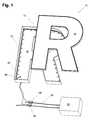
- FIG. 1is a prospective view showing the light system installed in a portion of a sign
- FIG. 2is a break out view of a portion of the sign of FIG. 1 showing the electrical connector joined to the flexible conductor strip;
- FIG. 3is a prospective view of the flexible conductor strip without the sockets
- FIG. 4is a prospective view of the flexible conductor strip with the sockets
- FIG. 5is an exploded view showing the primary layers of the flexible conductor strip
- FIG. 6is a partial cross-sectional view showing the preferred layers of the flexible conductor strip
- FIG. 7is a prospective view of the socket
- FIG. 8is a partial cross-sectional view of the socket, showing a light bulb being inserted into the socket and a boot being positioned over the light bulb;
- FIG. 9is a prospective view of a light source showing the typical light dispersion.
- FIG. 10is a prospective view of a light source in combination with a silicon boot, showing the improved light dispersion.
- the light system 10 shown in FIGS. 1-8preferably includes a channel sign 12 a power source 22 , a wire harness 24 a flexible conductor strip 28 , sockets 44 and a light 52 .
- the channel sign 12may be a typical channel sign with a cover 14 , walls 16 and a bottom 18 .
- the energy efficiency of this system 10advantageously offers a cooler lighting system allowing the channel sign 12 to be substantially smaller and to be used where fire hazard issues do not allow use of neon or other lighting systems, such as channel signs of less than 2′′ in width.
- the bottom 18 or walls 16may define a sign access port 20 sized to receive the wire harness 24 therethrough. While this invention contemplates a channel sign 12 as a component, one skilled in the art can understand that the system 10 may be operated in the absence of such a structure or in a different structure.
- Power source 22should provide sufficient power to flexible conductor strip 28 and lights 52 mounted thereto.
- Power source 22is a conventional encapsulated AC or DC power transformer.
- Wire harness 24is coupled to the power source 22 and to flexible conductor strip 28 . Multiple wires may be joined with an insulation displacement connector 58 as shown.
- the wire harness 24is joined to the flexible conductor strip 28 with an electrical connector assembly 26 as shown in FIG. 2 .
- Electrical connector assembly 26preferably is a termination connector, which is a two-part piece, male and female, with one portion secured to the wire harness 24 and the other secured to the flexible conductor strip 28 , such that the mating of the two-pieces electrically joins the wire harness 24 and the flexible conductor strip 28 .
- Wire harness 24is an optional component in that the flexible conductor strip 28 may be joined directly to the power source 22 through the electrical connector assembly 26 .
- Flexible conductor strip 28shown in FIGS. 3-6 is formed of multiple layers.
- conductors 34preferably of copper, are positioned between a base layer 36 and a top coverlay 32 and may be cut to length with a scissors.
- Top coverlay 32may be a thin dielectric laminate such as polyimide, polyester or polyethylene with a single-sided adhesive on the bottom side and preferably has defined solder pad openings 42 .
- Base layer 36may be a thin dielectric laminate such as polyimide, polyester or polyethylene with a single-sided adhesive on the top side.
- Flexible conductor strip 28is foldable, preferably with a bend radius of 0.05 inch or less, and is creasable.
- Silk screening 30may be position above the top coverlay 32 and double-sided tape 38 with a pealable strip 40 may be positioned adjacent the base 36 .
- Double-sided tape 38may be used to join the flexible conductor strip 28 to the channel sign 12 or other structure as shown in FIG. 2 .
- Flexible conductor strip 28may be encased between the cover 14 , walls 16 and bottom 18 of the channel sign 12 as indicated in FIG. 1 .
- Socket 44includes a circumferential wall 46 which meet near the axis to form a seat 48 , which is sized and shaped for stabilization of lights 52 .
- Pin receptacles 50preferably two, may be defined through the seat and sized to snugly receive conductive pins 54 of the lights 52 .
- Pin receptacles 50may be welded or otherwise bonded to conductors 34 through solder pad openings 42 , as shown in FIG. 4, thereby providing electrical communication between the flexible conductor strip 28 and the lights 52 .
- Lights 52preferably are miniature, high brightness, low voltage vacuum lamps, LED (light-emitting diode) lamps or other suitable light source and include conductive pins 54 , preferably two pins 54 . Lights 52 are selectively securable within the sockets 44 . One or more lights 52 may be attached to the flexible conductor strip 28 .
- Light boots 56preferably formed of silicon, are available in a wide variety of colors and translucent white, may be easily interchanged, are optional and are disposable.
- a light boot 56formed of thin polymer, are found to be useful to diffuse the directional lighting or narrow emission angle, e.g., hot spots, offered by LEDs to a radiating light, e.g., uniform light dispersion. This is demonstrated in a comparison of FIGS. 9 and 10, which shows the distribution of light rays.
- lights 52may be installed with the following steps.
- a flexible conductor strip 28is mounted, which may be permanently mounted, to a structure such as a channel sign 12 .
- Flexible conductor strip 28may be folded to the point of creasing, advantageously allowing connection of conductor 28 to an object with acute, sharp angles such as angles found in the letter “N” in a channel sign 12 .
- Power source 22supplies power through a wire harness 24 to the flexible conductor strip 28 .
- Lights 52receive electrical power through the flexible conductor strip 28 and are thereby empowered.
- Burned out lights 52may be disconnected from the flexible conductor strip 28 and replaced with an operable light 52 without removal or replacement of the flexible conductor strip 28 .
- various types of suitable light sourcesmay be exchange with any other suitable type of light source.
- Colored light sources 52may be used and exchanged with lights 52 of different colors.
- boots 56may be disposed over lights 52 to disperse directional lighting and alter coloration of the lighting. Where a white light source 52 is used, a boot 56 having one color may be removed and replaced with a boot 56 having a different color to change to color of the light. Thus, changing the color of light of a particular sign allows the flexible conductor strip 28 to remain in place throughout the entire process.
Landscapes
- Engineering & Computer Science (AREA)
- Physics & Mathematics (AREA)
- General Physics & Mathematics (AREA)
- Theoretical Computer Science (AREA)
- General Engineering & Computer Science (AREA)
- Illuminated Signs And Luminous Advertising (AREA)
- Fastening Of Light Sources Or Lamp Holders (AREA)
Abstract
Description
Claims (20)
Priority Applications (4)
| Application Number | Priority Date | Filing Date | Title |
|---|---|---|---|
| US09/845,580US6478450B1 (en) | 2001-04-30 | 2001-04-30 | Lighting system |
| CA002445962ACA2445962A1 (en) | 2001-04-30 | 2002-04-30 | Lighting system |
| PCT/US2002/014986WO2003008859A1 (en) | 2001-04-30 | 2002-04-30 | Lighting system |
| EP02780257AEP1390661A4 (en) | 2001-04-30 | 2002-04-30 | Lighting system |
Applications Claiming Priority (1)
| Application Number | Priority Date | Filing Date | Title |
|---|---|---|---|
| US09/845,580US6478450B1 (en) | 2001-04-30 | 2001-04-30 | Lighting system |
Publications (2)
| Publication Number | Publication Date |
|---|---|
| US20020159257A1 US20020159257A1 (en) | 2002-10-31 |
| US6478450B1true US6478450B1 (en) | 2002-11-12 |
Family
ID=25295556
Family Applications (1)
| Application Number | Title | Priority Date | Filing Date |
|---|---|---|---|
| US09/845,580Expired - LifetimeUS6478450B1 (en) | 2001-04-30 | 2001-04-30 | Lighting system |
Country Status (4)
| Country | Link |
|---|---|
| US (1) | US6478450B1 (en) |
| EP (1) | EP1390661A4 (en) |
| CA (1) | CA2445962A1 (en) |
| WO (1) | WO2003008859A1 (en) |
Cited By (32)
| Publication number | Priority date | Publication date | Assignee | Title |
|---|---|---|---|---|
| US20030009924A1 (en)* | 2000-11-03 | 2003-01-16 | Sajadian Zahra Nassrin | Outdoor numeric/allphabetic lighting |
| US20030067789A1 (en)* | 2001-08-18 | 2003-04-10 | Velez Michael A. | Channel letters |
| US6660935B2 (en)* | 2001-05-25 | 2003-12-09 | Gelcore Llc | LED extrusion light engine and connector therefor |
| WO2004017284A1 (en)* | 2002-08-14 | 2004-02-26 | Lighted Logos, L.C. | Portable lighted display |
| US6708433B1 (en)* | 2002-05-21 | 2004-03-23 | Lighted Logos, L. C. | Portable lighted display |
| USD499198S1 (en) | 2004-04-21 | 2004-11-30 | Ernest Cowan | Decorative light |
| US20050180135A1 (en)* | 2004-02-18 | 2005-08-18 | Gelcore Llc | Lighting apparatus for creating a substantially homogenous lit appearance |
| US20050221659A1 (en)* | 2004-04-06 | 2005-10-06 | Gelcore, Llc | Flexible high-power LED lighting system |
| US20050227529A1 (en)* | 2004-04-08 | 2005-10-13 | Gelcore Llc | Multi-conductor parallel splice connection |
| US20060035511A1 (en)* | 2004-04-06 | 2006-02-16 | Gelcore Llc | Flexible high-power LED lighting system |
| US20060087844A1 (en)* | 2001-06-29 | 2006-04-27 | Jagath Swaris | Modular mounting arrangement and method for light emitting diodes |
| US7114841B2 (en) | 2004-03-22 | 2006-10-03 | Gelcore Llc | Parallel/series LED strip |
| WO2006113991A1 (en)* | 2005-04-26 | 2006-11-02 | Tir Systems Ltd. | Integrated sign illumination system |
| US20060274526A1 (en)* | 2005-04-26 | 2006-12-07 | Tir Systems Ltd. | Integrated sign illumination system |
| US7156686B1 (en) | 2005-12-27 | 2007-01-02 | Gelcore Llc | Insulation displacement connection splice connector |
| US7251910B1 (en)* | 2003-07-22 | 2007-08-07 | General-Tech Holdings Limited | Electrical display device with individual display members |
| US20080080184A1 (en)* | 2006-10-03 | 2008-04-03 | Cao Group Inc. | Pixilated LED Light Source for Channel Letter Illumination |
| US20080192462A1 (en)* | 2007-02-14 | 2008-08-14 | James Steedly | Strip illumination device |
| US20080253116A1 (en)* | 2007-04-16 | 2008-10-16 | Yung-Chiang Liao | Lamp Structure |
| US20090013570A1 (en)* | 2007-04-10 | 2009-01-15 | Zdenko Grajcar | Apparatus and methods for the thermal regulation of light emitting diodes in signage |
| US20100061025A1 (en)* | 2008-09-09 | 2010-03-11 | Parker Francis J | LED module for sign channel letters and driving circuit |
| US20100140831A1 (en)* | 2008-12-05 | 2010-06-10 | Computerized Cutters, Inc. | Molded object-forming apparatus and method |
| USD620791S1 (en) | 2009-08-27 | 2010-08-03 | Once Innovations, Inc. | Re-usable package for lamps |
| USD621974S1 (en) | 2009-08-27 | 2010-08-17 | Once Innovations, Inc. | LED lamp |
| USD621973S1 (en) | 2009-08-27 | 2010-08-17 | Once Innovations, Inc. | Lamp |
| WO2010106472A1 (en) | 2009-03-17 | 2010-09-23 | Koninklijke Philips Electronics N.V. | Led strip for small channel letters |
| US20100277905A1 (en)* | 2009-05-01 | 2010-11-04 | Focal Point, L.L.C. | Recessed led down light |
| USD632171S1 (en) | 2009-08-27 | 2011-02-08 | Once Innovations, Inc. | Re-usable lamp package |
| US20110310601A1 (en)* | 2008-02-15 | 2011-12-22 | Shu-Fa Shao | Light-emitting diode line lamp |
| US9518709B2 (en) | 2013-11-04 | 2016-12-13 | Ningbo Suntec Lighting Co., Ltd | Lighting article comprising embedded LED strip and method thereof |
| US10634294B1 (en)* | 2016-01-13 | 2020-04-28 | OPē, LLC | Method of making a wavelength specific light source |
| USD936145S1 (en)* | 2019-07-26 | 2021-11-16 | My Gift Enterprise, LLC | Block sign |
Families Citing this family (18)
| Publication number | Priority date | Publication date | Assignee | Title |
|---|---|---|---|---|
| US6874909B2 (en)* | 2003-01-13 | 2005-04-05 | Carl R. Vanderschuit | Mood-enhancing illumination apparatus |
| US7014563B2 (en)* | 2001-09-28 | 2006-03-21 | Innovative Gaming Corporation Of America | Gaming machine candle device |
| US6932495B2 (en)* | 2001-10-01 | 2005-08-23 | Sloanled, Inc. | Channel letter lighting using light emitting diodes |
| US20060082315A1 (en)* | 2004-10-20 | 2006-04-20 | Timothy Chan | Method and system for attachment of light emmiting diodes to circuitry for use in lighting |
| US20070094902A1 (en)* | 2005-11-02 | 2007-05-03 | Universal Media Systems, Inc. | Wind resistant magnetic letter holders for large signs |
| DE102006023786A1 (en) | 2006-05-20 | 2007-11-22 | Maas & Roos Lichtwerbung Gmbh | Luminous advertising device, has light source formed by light application, which has support |
| US7410269B2 (en) | 2006-06-06 | 2008-08-12 | S.C. Johnson & Son, Inc. | Decorative light system |
| US7458698B2 (en) | 2006-06-15 | 2008-12-02 | S.C. Johnson & Son, Inc. | Decorative light system |
| CN101903701A (en) | 2007-12-21 | 2010-12-01 | 3M创新有限公司 | Thin flexible cable lighting assembly and preparation method thereof |
| DE102010016681A1 (en)* | 2010-04-28 | 2011-11-03 | Marcus Menden | Illumination device for use as symbol, letter or logo, comprises base body, in which multiple illuminating diodes are arranged distant to each other and are placed on flexible adhesive strips with integrated circuit paths |
| WO2011134830A1 (en) | 2010-04-28 | 2011-11-03 | Marcus Menden | Lighting device having a main body made of transparent material |
| ITMI20110775A1 (en)* | 2011-05-06 | 2012-11-07 | Insigna Industry S R L | LIGHTED SIGN |
| RU2497041C2 (en)* | 2011-11-25 | 2013-10-27 | Общество с ограниченной ответственностью "Тегас Электрик" | Assembly method of light-emitting-diode lamp, and light-emitting-diode lamp (versions) |
| US20200084855A1 (en)* | 2018-09-12 | 2020-03-12 | Eaton Intelligent Power Limited | Customized Photometric Data For Lighting System Designs |
| US10755609B1 (en)* | 2019-07-01 | 2020-08-25 | Theresa Harris | Solar-powered vivid view address numbers |
| CN213118859U (en)* | 2020-08-24 | 2021-05-04 | 临海市中天电子电器股份有限公司 | Portable solar strip lamp capable of being freely combined and installed |
| CN216902174U (en)* | 2022-01-12 | 2022-07-05 | 广东意高能源科技股份有限公司 | Novel magnetic type luminous mark |
| CN222952811U (en)* | 2024-06-24 | 2025-06-06 | 黄福忠 | Literal lamp box |
Citations (5)
| Publication number | Priority date | Publication date | Assignee | Title |
|---|---|---|---|---|
| US4173035A (en)* | 1977-12-01 | 1979-10-30 | Media Masters, Inc. | Tape strip for effecting moving light display |
| US5697175A (en)* | 1993-10-12 | 1997-12-16 | Spectralight, Inc. | Low power drain illuminated sign |
| US5918966A (en)* | 1995-03-03 | 1999-07-06 | W. Albrecht Gmbh & Co. Kg | Light with colored silicone cap |
| US6042248A (en)* | 1997-10-15 | 2000-03-28 | Lektron Industrial Supply, Inc. | LED assembly for illuminated signs |
| US6167648B1 (en)* | 1998-02-23 | 2001-01-02 | Frederick Dimmick | Illuminated modular sign having adjustable quick release modules |
- 2001
- 2001-04-30USUS09/845,580patent/US6478450B1/ennot_activeExpired - Lifetime
- 2002
- 2002-04-30WOPCT/US2002/014986patent/WO2003008859A1/ennot_activeApplication Discontinuation
- 2002-04-30CACA002445962Apatent/CA2445962A1/ennot_activeAbandoned
- 2002-04-30EPEP02780257Apatent/EP1390661A4/ennot_activeWithdrawn
Patent Citations (5)
| Publication number | Priority date | Publication date | Assignee | Title |
|---|---|---|---|---|
| US4173035A (en)* | 1977-12-01 | 1979-10-30 | Media Masters, Inc. | Tape strip for effecting moving light display |
| US5697175A (en)* | 1993-10-12 | 1997-12-16 | Spectralight, Inc. | Low power drain illuminated sign |
| US5918966A (en)* | 1995-03-03 | 1999-07-06 | W. Albrecht Gmbh & Co. Kg | Light with colored silicone cap |
| US6042248A (en)* | 1997-10-15 | 2000-03-28 | Lektron Industrial Supply, Inc. | LED assembly for illuminated signs |
| US6167648B1 (en)* | 1998-02-23 | 2001-01-02 | Frederick Dimmick | Illuminated modular sign having adjustable quick release modules |
Cited By (57)
| Publication number | Priority date | Publication date | Assignee | Title |
|---|---|---|---|---|
| US20030009924A1 (en)* | 2000-11-03 | 2003-01-16 | Sajadian Zahra Nassrin | Outdoor numeric/allphabetic lighting |
| US6660935B2 (en)* | 2001-05-25 | 2003-12-09 | Gelcore Llc | LED extrusion light engine and connector therefor |
| US20080266858A1 (en)* | 2001-05-25 | 2008-10-30 | Gelcore, Llc (Now Lumination Llc) | Illuminated signage employing light-emitting diodes |
| US7217012B2 (en) | 2001-05-25 | 2007-05-15 | Lumination, Llc | Illuminated signage employing light emitting diodes |
| US7399105B2 (en) | 2001-05-25 | 2008-07-15 | Lumination Llc | Illuminated signage employing light emitting diodes |
| US20050030765A1 (en)* | 2001-05-25 | 2005-02-10 | Paul Southard | Illuminated signage employing light emitting diodes |
| US7686477B2 (en) | 2001-05-25 | 2010-03-30 | Lumination Llc | Flexible lighting strips employing light-emitting diodes |
| US20070285933A1 (en)* | 2001-05-25 | 2007-12-13 | Gelcore, Llc (Now Lumination, Llc) | Illuminated signage employing light emitting diodes |
| US20060087844A1 (en)* | 2001-06-29 | 2006-04-27 | Jagath Swaris | Modular mounting arrangement and method for light emitting diodes |
| US7387406B2 (en)* | 2001-06-29 | 2008-06-17 | Permlight Products, Inc. | Modular mounting arrangement and method for light emitting diodes |
| US20030067789A1 (en)* | 2001-08-18 | 2003-04-10 | Velez Michael A. | Channel letters |
| US6860629B2 (en)* | 2001-08-18 | 2005-03-01 | Michael Velez | Solid transparent acrylic letters |
| US6708433B1 (en)* | 2002-05-21 | 2004-03-23 | Lighted Logos, L. C. | Portable lighted display |
| US6907685B1 (en) | 2002-05-21 | 2005-06-21 | Lighted Logos, L.C. | Portable lighted display |
| WO2004017284A1 (en)* | 2002-08-14 | 2004-02-26 | Lighted Logos, L.C. | Portable lighted display |
| US7251910B1 (en)* | 2003-07-22 | 2007-08-07 | General-Tech Holdings Limited | Electrical display device with individual display members |
| US20050180135A1 (en)* | 2004-02-18 | 2005-08-18 | Gelcore Llc | Lighting apparatus for creating a substantially homogenous lit appearance |
| US7237925B2 (en) | 2004-02-18 | 2007-07-03 | Lumination Llc | Lighting apparatus for creating a substantially homogenous lit appearance |
| US7114841B2 (en) | 2004-03-22 | 2006-10-03 | Gelcore Llc | Parallel/series LED strip |
| US20060035511A1 (en)* | 2004-04-06 | 2006-02-16 | Gelcore Llc | Flexible high-power LED lighting system |
| US7210957B2 (en) | 2004-04-06 | 2007-05-01 | Lumination Llc | Flexible high-power LED lighting system |
| US8348469B2 (en) | 2004-04-06 | 2013-01-08 | Ge Lighting Solutions Llc | Flexible high-power LED lighting system |
| US20070190845A1 (en)* | 2004-04-06 | 2007-08-16 | Gelcore Llc | Flexible high-power led lighting system |
| US7429186B2 (en) | 2004-04-06 | 2008-09-30 | Lumination Llc | Flexible high-power LED lighting system |
| US20050221659A1 (en)* | 2004-04-06 | 2005-10-06 | Gelcore, Llc | Flexible high-power LED lighting system |
| US20050227529A1 (en)* | 2004-04-08 | 2005-10-13 | Gelcore Llc | Multi-conductor parallel splice connection |
| USD499198S1 (en) | 2004-04-21 | 2004-11-30 | Ernest Cowan | Decorative light |
| US20060274526A1 (en)* | 2005-04-26 | 2006-12-07 | Tir Systems Ltd. | Integrated sign illumination system |
| WO2006113991A1 (en)* | 2005-04-26 | 2006-11-02 | Tir Systems Ltd. | Integrated sign illumination system |
| US7156686B1 (en) | 2005-12-27 | 2007-01-02 | Gelcore Llc | Insulation displacement connection splice connector |
| US20080080184A1 (en)* | 2006-10-03 | 2008-04-03 | Cao Group Inc. | Pixilated LED Light Source for Channel Letter Illumination |
| US9297525B2 (en)* | 2006-10-03 | 2016-03-29 | Epistar Corporation | Pixilated LED light source for channel letter illumination |
| US20100117560A1 (en)* | 2006-10-03 | 2010-05-13 | Cao Group, Inc. | Pixilated LED Light Source for Channel Letter Illumination |
| US20080192462A1 (en)* | 2007-02-14 | 2008-08-14 | James Steedly | Strip illumination device |
| US7815341B2 (en) | 2007-02-14 | 2010-10-19 | Permlight Products, Inc. | Strip illumination device |
| US8183794B2 (en)* | 2007-04-10 | 2012-05-22 | Nexxus Lighting, Inc. | Apparatus and methods for the thermal regulation of light emitting diodes in signage |
| US20110203149A1 (en)* | 2007-04-10 | 2011-08-25 | Nexxus Lighting, Inc. | Apparatus and methods for the thermal regulation of light emitting diodes in signage |
| US20090013570A1 (en)* | 2007-04-10 | 2009-01-15 | Zdenko Grajcar | Apparatus and methods for the thermal regulation of light emitting diodes in signage |
| US7948190B2 (en) | 2007-04-10 | 2011-05-24 | Nexxus Lighting, Inc. | Apparatus and methods for the thermal regulation of light emitting diodes in signage |
| US20080253116A1 (en)* | 2007-04-16 | 2008-10-16 | Yung-Chiang Liao | Lamp Structure |
| US20110310601A1 (en)* | 2008-02-15 | 2011-12-22 | Shu-Fa Shao | Light-emitting diode line lamp |
| US8611057B2 (en) | 2008-09-09 | 2013-12-17 | Inshore Holdings, Llc | LED module for sign channel letters and driving circuit |
| US20110085271A1 (en)* | 2008-09-09 | 2011-04-14 | Inshore Holdings, Llc | LED Modules for Sign Channel Letters and Driving Circuit |
| US8305717B2 (en) | 2008-09-09 | 2012-11-06 | Inshore Holdings, Llc | LED modules for sign channel letters and driving circuit |
| US20100061025A1 (en)* | 2008-09-09 | 2010-03-11 | Parker Francis J | LED module for sign channel letters and driving circuit |
| US20100140831A1 (en)* | 2008-12-05 | 2010-06-10 | Computerized Cutters, Inc. | Molded object-forming apparatus and method |
| CN102356267A (en)* | 2009-03-17 | 2012-02-15 | 皇家飞利浦电子股份有限公司 | Led strip for small channel letters |
| WO2010106472A1 (en) | 2009-03-17 | 2010-09-23 | Koninklijke Philips Electronics N.V. | Led strip for small channel letters |
| US20100277905A1 (en)* | 2009-05-01 | 2010-11-04 | Focal Point, L.L.C. | Recessed led down light |
| US8022641B2 (en) | 2009-05-01 | 2011-09-20 | Focal Point, L.L.C. | Recessed LED down light |
| USD620791S1 (en) | 2009-08-27 | 2010-08-03 | Once Innovations, Inc. | Re-usable package for lamps |
| USD632171S1 (en) | 2009-08-27 | 2011-02-08 | Once Innovations, Inc. | Re-usable lamp package |
| USD621973S1 (en) | 2009-08-27 | 2010-08-17 | Once Innovations, Inc. | Lamp |
| USD621974S1 (en) | 2009-08-27 | 2010-08-17 | Once Innovations, Inc. | LED lamp |
| US9518709B2 (en) | 2013-11-04 | 2016-12-13 | Ningbo Suntec Lighting Co., Ltd | Lighting article comprising embedded LED strip and method thereof |
| US10634294B1 (en)* | 2016-01-13 | 2020-04-28 | OPē, LLC | Method of making a wavelength specific light source |
| USD936145S1 (en)* | 2019-07-26 | 2021-11-16 | My Gift Enterprise, LLC | Block sign |
Also Published As
| Publication number | Publication date |
|---|---|
| EP1390661A1 (en) | 2004-02-25 |
| EP1390661A4 (en) | 2005-12-14 |
| WO2003008859A1 (en) | 2003-01-30 |
| CA2445962A1 (en) | 2003-01-30 |
| US20020159257A1 (en) | 2002-10-31 |
Similar Documents
| Publication | Publication Date | Title |
|---|---|---|
| US6478450B1 (en) | Lighting system | |
| US10660172B2 (en) | Modular light fixture with power pack | |
| US7387403B2 (en) | Modular lighting apparatus | |
| US7357528B2 (en) | CCFL illuminated device and method of use | |
| US6616310B1 (en) | CCFL illuminated device | |
| US6540373B2 (en) | Lighting system | |
| US8215786B2 (en) | Flexible perimeter lighting apparatus | |
| EP1275101B1 (en) | A flexible light track for signage | |
| CN106461196B (en) | Light emitting assembly | |
| US6454431B1 (en) | Lighting system | |
| US20030112627A1 (en) | Flexible sign illumination apparatus, system and method | |
| US9410665B2 (en) | Flexible ribbon LED module | |
| US7234840B2 (en) | Lighting element and lighting element fixture with said element | |
| US20060215398A1 (en) | LED module and system of LED modules with integral branch connectors | |
| CN105870749A (en) | Switching joint and illuminating device | |
| CN222881026U (en) | A packaging carrier for light emitting diode | |
| CN215336019U (en) | Novel line lamp of convenient butt joint | |
| CN221780595U (en) | An outdoor light strip that can be cut arbitrarily | |
| KR200276179Y1 (en) | A fluorescent Lamp connecting assembly in a notice board | |
| KR20170001174U (en) | Expandable LED Module Lighting Equipment | |
| HK1230267A1 (en) | Lighting assembly |
Legal Events
| Date | Code | Title | Description |
|---|---|---|---|
| AS | Assignment | Owner name:LUMIFICIENT TECHNOLOGIES LLC, MINNESOTA Free format text:ASSIGNMENT OF ASSIGNORS INTEREST;ASSIGNOR:GRAJCA, ZDENKO;REEL/FRAME:012984/0077 Effective date:20020601 | |
| FEPP | Fee payment procedure | Free format text:ENTITY STATUS SET TO SMALL (ORIGINAL EVENT CODE: SMAL); ENTITY STATUS OF PATENT OWNER: SMALL ENTITY | |
| STCF | Information on status: patent grant | Free format text:PATENTED CASE | |
| REMI | Maintenance fee reminder mailed | ||
| FPAY | Fee payment | Year of fee payment:4 | |
| SULP | Surcharge for late payment | ||
| AS | Assignment | Owner name:LUMIFICIENT CORPORATION, MINNESOTA Free format text:ASSIGNMENT OF ASSIGNORS INTEREST;ASSIGNOR:LUMIFICIENT TECHNOLOGIES, LLC;REEL/FRAME:020371/0826 Effective date:20080107 | |
| AS | Assignment | Owner name:LUMIFICIENT CORPORATION, MINNESOTA Free format text:ASSIGNMENT OF ASSIGNORS INTEREST;ASSIGNOR:LUMIFICIENT TECHNOLOGIES, LLC;REEL/FRAME:020362/0697 Effective date:20080107 | |
| AS | Assignment | Owner name:PROSPERAN BANK, MINNESOTA Free format text:SECURITY AGREEMENT;ASSIGNOR:LUMIFICIENT CORPORATION;REEL/FRAME:020385/0879 Effective date:20080110 | |
| FPAY | Fee payment | Year of fee payment:8 | |
| AS | Assignment | Owner name:REVOLUTION LIGHTING TECHNOLOGIES, INC., CONNECTICU Free format text:CHANGE OF NAME;ASSIGNOR:NEXXUS LIGHTING, INC.;REEL/FRAME:032636/0631 Effective date:20121116 | |
| FPAY | Fee payment | Year of fee payment:12 | |
| AS | Assignment | Owner name:BANK OF AMERICA, N.A., CONNECTICUT Free format text:SECURITY INTEREST;ASSIGNORS:REVOLUTION LIGHTING TECHNOLOGIES, INC.;LUMIFICIENT CORPORATION;LIGHTING INTEGRATION TECHNOLOGIES, LLC;AND OTHERS;REEL/FRAME:033579/0700 Effective date:20140820 | |
| AS | Assignment | Owner name:ALERUS FINANCIAL, N.A., ASSIGNEE OF THE FDIC, RECE Free format text:RELEASE BY SECURED PARTY;ASSIGNOR:LUMIFICIENT CORPORATION;REEL/FRAME:033886/0941 Effective date:20080110 |