US6478082B1 - Heat dissipating apparatus with nest wind duct - Google Patents
Heat dissipating apparatus with nest wind ductDownload PDFInfo
- Publication number
- US6478082B1 US6478082B1US09/576,870US57687000AUS6478082B1US 6478082 B1US6478082 B1US 6478082B1US 57687000 AUS57687000 AUS 57687000AUS 6478082 B1US6478082 B1US 6478082B1
- Authority
- US
- United States
- Prior art keywords
- thermally conductive
- passages
- heat dissipating
- frame member
- dissipating structure
- Prior art date
- Legal status (The legal status is an assumption and is not a legal conclusion. Google has not performed a legal analysis and makes no representation as to the accuracy of the status listed.)
- Expired - Fee Related
Links
- 239000007769metal materialSubstances0.000claimsabstractdescription6
- 239000012530fluidSubstances0.000claims14
- 229910010293ceramic materialInorganic materials0.000claims1
- 239000000919ceramicSubstances0.000abstractdescription4
- 238000004026adhesive bondingMethods0.000abstractdescription3
- 238000005219brazingMethods0.000abstractdescription3
- 238000005266castingMethods0.000abstractdescription3
- 238000005242forgingMethods0.000abstractdescription3
- 238000005245sinteringMethods0.000abstractdescription3
- 238000005476solderingMethods0.000abstractdescription3
- 238000003466weldingMethods0.000abstractdescription3
- 239000000203mixtureSubstances0.000abstractdescription2
- 239000002131composite materialSubstances0.000description5
- 230000000694effectsEffects0.000description5
- 230000017525heat dissipationEffects0.000description4
- 229910052782aluminiumInorganic materials0.000description2
- XAGFODPZIPBFFR-UHFFFAOYSA-NaluminiumChemical compound[Al]XAGFODPZIPBFFR-UHFFFAOYSA-N0.000description2
- 238000001125extrusionMethods0.000description2
- 229910052751metalInorganic materials0.000description2
- 239000002184metalSubstances0.000description2
- 238000012986modificationMethods0.000description2
- 230000004048modificationEffects0.000description2
- 230000002093peripheral effectEffects0.000description2
- 238000006467substitution reactionMethods0.000description2
- 238000000926separation methodMethods0.000description1
Images


Classifications
- F—MECHANICAL ENGINEERING; LIGHTING; HEATING; WEAPONS; BLASTING
- F28—HEAT EXCHANGE IN GENERAL
- F28F—DETAILS OF HEAT-EXCHANGE AND HEAT-TRANSFER APPARATUS, OF GENERAL APPLICATION
- F28F13/00—Arrangements for modifying heat-transfer, e.g. increasing, decreasing
- F28F13/003—Arrangements for modifying heat-transfer, e.g. increasing, decreasing by using permeable mass, perforated or porous materials
- F—MECHANICAL ENGINEERING; LIGHTING; HEATING; WEAPONS; BLASTING
- F28—HEAT EXCHANGE IN GENERAL
- F28F—DETAILS OF HEAT-EXCHANGE AND HEAT-TRANSFER APPARATUS, OF GENERAL APPLICATION
- F28F3/00—Plate-like or laminated elements; Assemblies of plate-like or laminated elements
- F28F3/02—Elements or assemblies thereof with means for increasing heat-transfer area, e.g. with fins, with recesses, with corrugations
- F—MECHANICAL ENGINEERING; LIGHTING; HEATING; WEAPONS; BLASTING
- F28—HEAT EXCHANGE IN GENERAL
- F28F—DETAILS OF HEAT-EXCHANGE AND HEAT-TRANSFER APPARATUS, OF GENERAL APPLICATION
- F28F7/00—Elements not covered by group F28F1/00, F28F3/00 or F28F5/00
- F28F7/02—Blocks traversed by passages for heat-exchange media
- H—ELECTRICITY
- H01—ELECTRIC ELEMENTS
- H01L—SEMICONDUCTOR DEVICES NOT COVERED BY CLASS H10
- H01L23/00—Details of semiconductor or other solid state devices
- H01L23/34—Arrangements for cooling, heating, ventilating or temperature compensation ; Temperature sensing arrangements
- H01L23/36—Selection of materials, or shaping, to facilitate cooling or heating, e.g. heatsinks
- H01L23/367—Cooling facilitated by shape of device
- H—ELECTRICITY
- H01—ELECTRIC ELEMENTS
- H01L—SEMICONDUCTOR DEVICES NOT COVERED BY CLASS H10
- H01L23/00—Details of semiconductor or other solid state devices
- H01L23/34—Arrangements for cooling, heating, ventilating or temperature compensation ; Temperature sensing arrangements
- H01L23/46—Arrangements for cooling, heating, ventilating or temperature compensation ; Temperature sensing arrangements involving the transfer of heat by flowing fluids
- H01L23/467—Arrangements for cooling, heating, ventilating or temperature compensation ; Temperature sensing arrangements involving the transfer of heat by flowing fluids by flowing gases, e.g. air
- F—MECHANICAL ENGINEERING; LIGHTING; HEATING; WEAPONS; BLASTING
- F28—HEAT EXCHANGE IN GENERAL
- F28D—HEAT-EXCHANGE APPARATUS, NOT PROVIDED FOR IN ANOTHER SUBCLASS, IN WHICH THE HEAT-EXCHANGE MEDIA DO NOT COME INTO DIRECT CONTACT
- F28D15/00—Heat-exchange apparatus with the intermediate heat-transfer medium in closed tubes passing into or through the conduit walls ; Heat-exchange apparatus employing intermediate heat-transfer medium or bodies
- F28D15/02—Heat-exchange apparatus with the intermediate heat-transfer medium in closed tubes passing into or through the conduit walls ; Heat-exchange apparatus employing intermediate heat-transfer medium or bodies in which the medium condenses and evaporates, e.g. heat pipes
- F28D15/0275—Arrangements for coupling heat-pipes together or with other structures, e.g. with base blocks; Heat pipe cores
- H—ELECTRICITY
- H01—ELECTRIC ELEMENTS
- H01L—SEMICONDUCTOR DEVICES NOT COVERED BY CLASS H10
- H01L2924/00—Indexing scheme for arrangements or methods for connecting or disconnecting semiconductor or solid-state bodies as covered by H01L24/00
- H01L2924/0001—Technical content checked by a classifier
- H01L2924/0002—Not covered by any one of groups H01L24/00, H01L24/00 and H01L2224/00
Definitions
- the present inventionrelates to a heat dissipating apparatus with nest wind duct, especially to a heat dissipating apparatus with nest wind duct, which has fast heat conducting effect.
- the conventional heat dissipating apparatus of electronic deviceare generally designed for heat dissipation of CPU, i.e., for removing heat generated by the CPU out of the package.
- the heat dissipating apparatusbecome increasingly important as the speed of CPU increases.
- the conventional heat dissipating apparatus of electronic devicecan be classified to aluminum extrusion manifold type and heat pipe type.
- the aluminum extrusion manifold type heat dissipating apparatuscomprises a bulky base integrally with a plurality of manifolds. The bulky base is in contact with electronic device requiring heat dissipation and the heat is dissipated only by the manifolds.
- the heat pipe type heat dissipating apparatuscomprises a heat pipe connected with a plurality of heat dissipating plates.
- the peripheral and inner part of the ductshave excellent thermal conducting effect.
- the present inventionprovides a heat dissipating apparatus with nest wind duct arranged corresponding to a horizontal flow of air.
- the heat dissipating apparatusis composed of nest wind duct with a plurality of through passages to form at least two vertical porous surfaces for the heat dissipating apparatus.
- the wind ductcan be composed of strip fixture having element selected from the group consisting of thin rectangular pipe, circular pipe, hexagonal pipe or the composition thereof.
- the wind ductalso can be formed by integrally forging, extruding, casting porous ceramic or metal materials.
- the wind ductalso can be formed with strip and panel fixtures assembled by soldering, gluing, welding, brazing or sintering. Therefore, at least one lateral surface of the heat dissipating apparatus is in contact with a thermal source or a plate of heat transfer.
- FIG. 1is a perspective view of the present invention
- FIG. 2is a perspective view of the preferred embodiment of the present invention.
- FIG. 3is sectional view of the first embodiment of the present invention.
- FIG. 4is sectional view of the second embodiment of the present invention.
- FIG. 5is sectional view of the third embodiment of the present invention.
- FIG. 6is sectional view of the fourth embodiment of the present invention.
- FIG. 7is sectional view of the fifth embodiment of the present invention.
- FIG. 8is sectional view of the sixth embodiment of the present invention.
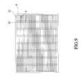
- FIG. 9is sectional view of the seventh embodiment of the present invention.
- FIG. 10is sectional view of the eighth embodiment of the present invention.
- FIG. 11is sectional view of the ninth embodiment of the present invention.
- the present inventionis intended to provide a heat dissipating apparatus with nest wind duct.
- the nest-like heat dissipating apparatus 1is arranged corresponding to a horizontal flow and comprises a wind duct structure 10 .
- the wind duct structure 10is composed of structure 4 integrally made of strip fixture 2 or panel fixture 3 .
- the wind duct structure 10is assembled to provide air-conducting or heat-exchange heat dissipating porous conduit.
- the shape of the wind duct structure 10is extruding and continuous to achieve omni-directional heat dissipating.
- the strip fixture 2is composed of thin rectangular pipe 21 , circular pipe 22 , hexagonal pipe 23 , semi-circular pipe or octagonal pipe etc.
- the panel fixture 3is formed by stacking plate 31 having ribs 32 or protrusions.
- the structure 4is formed by forging, extruding, casting porous ceramics or metal or the combination of strip fixture 2 and panel structure 3 by soldering, gluing, welding, brazing or sintering. Therefore, at least one lateral side of the heat dissipating apparatus 1 is in contact with the thermal source 5 or plate of heat transfer 9 .
- the wind duct structure 10provides passages toward a fan 6 and a guiding hood 7 is provided between the fan 6 and the wind duct structure 10 .
- a frame 8is provided to cover the wind duct structure 10 , alternatively, the frame 8 and the guiding hood 7 can be integrally formed.
- FIG. 1shows the nest heat dissipating apparatus 1 composed of a plurality of panel fixtures 3 .
- the panel fixtures 3comprises a plurality of plate 31 with integrally pressed horn-shaped protrusions 32 .
- the top of the nest-like heat dissipating apparatus 1has a top plate 36 , both sides of the plate 31 has downward-folded flange 37 to facilitate the stacking of the plate 31 on lateral side thereof.
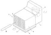
- a fan 6is arranged corresponding to the air inlet or air outlet of the nest-like heat dissipating apparatus 1 and has a predetermined separation with the nest-like heat dissipating apparatus 1 .
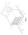
- FIG. 2shows a perspective view of the preferred embodiment of the present invention.
- the nest-like heat dissipating apparatus 1is provided with the frame 8 on the perimeter thereof, the fan 6 and the guiding hood 7 .
- the nest-like heat dissipating apparatus 1comprises an integrally manufactured structure 4 .
- the structure 4can be chessboard-like wind duct structure 10 .
- the fan 6is arranged within the guiding hood 7 and provide exhaust and blow effect. Therefore, the heat can be forced to remove.
- the guiding hood 7is provided.
- the frame 8is provided to receive heat from ambience.
- heat form a thermal source 5can be conducted to the nest-like heat dissipating apparatus 1 through the plate of heat transfer 9 .
- a heat pipe 50is inserted to any hole of the structure 4 , through which the heat is conducted to the chessboard-like wind duct structure 10 .
- heatcan be transmitted to the chessboard-like wind duct structure 10 through upward, downward, left, right or inner directions.
- the plate of heat transfer 9can be made of metal plate, ceramic plate, planar heat pipe.
- the structure 4is composed of rectangular conduit 21 .
- the structure 4is composed of circular conduit 22 .
- the structure 4is composed of hexagonal conduit 23 .
- the above-mentioned three structures 4are composed of simple element.
- FIG. 6shows a composite structure wherein a circular conduit 22 is alternatively arranged with a planar plate 36 .
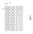
- FIG. 7shows another composite structure wherein a semi-circular conduit 34 is alternatively arranged with a planar plate 36 and two semi-circular conduits 34 form a circular shape.
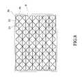
- FIG. 8shows still another composite structure wherein a plate 33 with triangular protrusions is alternatively arranged with a planar plate 36 .
- FIG. 9shows another composite structure wherein a plurality of planar plates 36 are stacked and separated by rib 32 to achieve compact structure.
- the structure 4is composed of rectangular corrugations 35 .
- a helicoid conduit 60replace the frame 8
- a plurality of circular pipes 22are bundled to form a beam structure 2 to replace the wind duct structure 10 .
- the wind duct structure 10can be the configurations shown in FIGS. 3 to 11 .
- the present inventionprovides a heat dissipating apparatus with nest wind ducts.
- the ductsprovide horizontal communication and provide porous structure.
- the peripheral and inner part of the ductshave excellent thermal conducting effect.
- a heat pipecan be inserted into the conduit of the heat dissipating apparatus or a heat dissipating block can be assembled with the heat dissipating apparatus to enhance the heat dissipating effect.
Landscapes
- Engineering & Computer Science (AREA)
- Physics & Mathematics (AREA)
- Thermal Sciences (AREA)
- Mechanical Engineering (AREA)
- General Engineering & Computer Science (AREA)
- Condensed Matter Physics & Semiconductors (AREA)
- General Physics & Mathematics (AREA)
- Computer Hardware Design (AREA)
- Microelectronics & Electronic Packaging (AREA)
- Power Engineering (AREA)
- Chemical & Material Sciences (AREA)
- Materials Engineering (AREA)
- Dispersion Chemistry (AREA)
- Cooling Or The Like Of Semiconductors Or Solid State Devices (AREA)
Abstract
Description
The present invention relates to a heat dissipating apparatus with nest wind duct, especially to a heat dissipating apparatus with nest wind duct, which has fast heat conducting effect.
The conventional heat dissipating apparatus of electronic device are generally designed for heat dissipation of CPU, i.e., for removing heat generated by the CPU out of the package. The heat dissipating apparatus become increasingly important as the speed of CPU increases. The conventional heat dissipating apparatus of electronic device can be classified to aluminum extrusion manifold type and heat pipe type. The aluminum extrusion manifold type heat dissipating apparatus comprises a bulky base integrally with a plurality of manifolds. The bulky base is in contact with electronic device requiring heat dissipation and the heat is dissipated only by the manifolds. The heat pipe type heat dissipating apparatus comprises a heat pipe connected with a plurality of heat dissipating plates. However, the heat dissipation is carried out only by the heat pipe and the heat dissipation is deteriorated when the heat pipe is slantingly arranged. Moreover, a multiple-plate composite heat dissipating apparatus is also proposed and much space is left for improvement.
It is the object of the invention to provide a heat dissipating apparatus with nest wind duct, the duct providing horizontal air flowing passages and having high porosity. The peripheral and inner part of the ducts have excellent thermal conducting effect.
To achieve the above object, the present invention provides a heat dissipating apparatus with nest wind duct arranged corresponding to a horizontal flow of air. The heat dissipating apparatus is composed of nest wind duct with a plurality of through passages to form at least two vertical porous surfaces for the heat dissipating apparatus. The wind duct can be composed of strip fixture having element selected from the group consisting of thin rectangular pipe, circular pipe, hexagonal pipe or the composition thereof. Moreover, the wind duct also can be formed by integrally forging, extruding, casting porous ceramic or metal materials. Moreover, the wind duct also can be formed with strip and panel fixtures assembled by soldering, gluing, welding, brazing or sintering. Therefore, at least one lateral surface of the heat dissipating apparatus is in contact with a thermal source or a plate of heat transfer.
The various objects and advantages of the present invention will be more readily understood from the following detailed description when read in conjunction with the appended drawing, in which:
FIG. 1 is a perspective view of the present invention;
FIG. 2 is a perspective view of the preferred embodiment of the present invention;
FIG. 3 is sectional view of the first embodiment of the present invention;
FIG. 4 is sectional view of the second embodiment of the present invention;
FIG. 5 is sectional view of the third embodiment of the present invention;
FIG. 6 is sectional view of the fourth embodiment of the present invention;
FIG. 7 is sectional view of the fifth embodiment of the present invention;
FIG. 8 is sectional view of the sixth embodiment of the present invention;
FIG. 9 is sectional view of the seventh embodiment of the present invention;
FIG. 10 is sectional view of the eighth embodiment of the present invention;
FIG. 11 is sectional view of the ninth embodiment of the present invention;
With reference now to FIGS. 1 to11, the present invention is intended to provide a heat dissipating apparatus with nest wind duct. The nest-likeheat dissipating apparatus 1 is arranged corresponding to a horizontal flow and comprises awind duct structure 10. Thewind duct structure 10 is composed ofstructure 4 integrally made ofstrip fixture 2 or panel fixture3. Thewind duct structure 10 is assembled to provide air-conducting or heat-exchange heat dissipating porous conduit. The shape of thewind duct structure 10 is extruding and continuous to achieve omni-directional heat dissipating. Thestrip fixture 2 is composed of thinrectangular pipe 21,circular pipe 22,hexagonal pipe 23, semi-circular pipe or octagonal pipe etc. The panel fixture3 is formed by stackingplate 31 havingribs 32 or protrusions. Thestructure 4 is formed by forging, extruding, casting porous ceramics or metal or the combination ofstrip fixture 2 and panel structure3 by soldering, gluing, welding, brazing or sintering. Therefore, at least one lateral side of theheat dissipating apparatus 1 is in contact with thethermal source 5 or plate ofheat transfer 9. Thewind duct structure 10 provides passages toward afan 6 and aguiding hood 7 is provided between thefan 6 and thewind duct structure 10. Aframe 8 is provided to cover thewind duct structure 10, alternatively, theframe 8 and the guidinghood 7 can be integrally formed.
FIG. 1 shows the nestheat dissipating apparatus 1 composed of a plurality of panel fixtures3. As shown in FIG. 9, the panel fixtures3 comprises a plurality ofplate 31 with integrally pressed horn-shaped protrusions 32. As shown in FIG. 1, the top of the nest-likeheat dissipating apparatus 1 has atop plate 36, both sides of theplate 31 has downward-foldedflange 37 to facilitate the stacking of theplate 31 on lateral side thereof. As shown in FIG. 1, afan 6 is arranged corresponding to the air inlet or air outlet of the nest-likeheat dissipating apparatus 1 and has a predetermined separation with the nest-likeheat dissipating apparatus 1.
FIG. 2 shows a perspective view of the preferred embodiment of the present invention. For practical application, the nest-likeheat dissipating apparatus 1 is provided with theframe 8 on the perimeter thereof, thefan 6 and theguiding hood 7. The nest-likeheat dissipating apparatus 1 comprises an integrally manufacturedstructure 4. For example, thestructure 4 can be chessboard-likewind duct structure 10. Thefan 6 is arranged within the guidinghood 7 and provide exhaust and blow effect. Therefore, the heat can be forced to remove. To guide the flow direction of the air, the guidinghood 7 is provided. In the present invention, theframe 8 is provided to receive heat from ambience. For example, heat form athermal source 5 can be conducted to the nest-likeheat dissipating apparatus 1 through the plate ofheat transfer 9. Alternatively, as shown in FIG. 1, aheat pipe 50 is inserted to any hole of thestructure 4, through which the heat is conducted to the chessboard-likewind duct structure 10. As shown in FIG. 2, heat can be transmitted to the chessboard-likewind duct structure 10 through upward, downward, left, right or inner directions. The plate ofheat transfer 9 can be made of metal plate, ceramic plate, planar heat pipe.
As shown in FIG. 3, thestructure 4 is composed ofrectangular conduit 21. As shown in FIG. 4, thestructure 4 is composed ofcircular conduit 22. As shown in FIG. 5, thestructure 4 is composed of hexagonal conduit23.The above-mentioned threestructures 4 are composed of simple element. FIG. 6 shows a composite structure wherein acircular conduit 22 is alternatively arranged with aplanar plate 36. FIG. 7 shows another composite structure wherein asemi-circular conduit 34 is alternatively arranged with aplanar plate 36 and twosemi-circular conduits 34 form a circular shape. FIG. 8 shows still another composite structure wherein aplate 33 with triangular protrusions is alternatively arranged with aplanar plate 36. FIG. 9 shows another composite structure wherein a plurality ofplanar plates 36 are stacked and separated byrib 32 to achieve compact structure. As shown in FIG. 10, thestructure 4 is composed ofrectangular corrugations 35. As shown in FIG. 11, ahelicoid conduit 60 replace theframe 8, and a plurality ofcircular pipes 22 are bundled to form abeam structure 2 to replace thewind duct structure 10. Moreover, thewind duct structure 10 can be the configurations shown in FIGS. 3 to11.
To sum up, the present invention provides a heat dissipating apparatus with nest wind ducts. The ducts provide horizontal communication and provide porous structure. The peripheral and inner part of the ducts have excellent thermal conducting effect. A heat pipe can be inserted into the conduit of the heat dissipating apparatus or a heat dissipating block can be assembled with the heat dissipating apparatus to enhance the heat dissipating effect.
Although the present invention has been described with reference to the preferred embodiment thereof, it will be understood that the invention is not limited to the details thereof. Various substitutions and modifications have suggested in the foregoing description, and other will occur to those of ordinary skill in the art. Therefore, all such substitutions and modifications are intended to be embraced within the scope of the invention as defined in the appended claims.
Claims (17)
1. A heat dissipating structure comprising:
a fan for driving fluid flow in a longitudinal direction;
a thermally conductive frame member longitudinally aligned with said fan, defining a plurality of longitudinally extending tubular members forming a longitudinally directed array of passages, each of said passages being partitioned each from the other, said each of said tubular members defining a thermal contact surface and being open on opposing sides thereof to allow fluid to continuously flow through each of said passages, each of said passages defining a continuous unidirectional fluid path parallel to said thermal contact surface for drawing thermal energy from a heat source in thermal communication with an external surface of said thermally conductive frame member, wherein each of said passages has a substantially rectangular cross-section.
2. The heat dissipating structure as recited inclaim 1 , wherein a thermally conductive plate is positioned between said thermally conductive frame member and said heat source, said thermally conductive plate being in thermal communication with both said thermally conductive frame member and said heat source.
3. The heat dissipating structure as recited inclaim 1 , wherein said thermally conductive frame member and said array of passages are formed from a thermally conductive metal material.
4. The heat dissipating structure as recited inclaim 1 , wherein said thermally conductive frame member has a substantially rectangular cross-section.
5. The heat dissipating structure as recited inclaim 1 , wherein said external surface of said thermally conductive frame member has a substantially arcuate contour.
6. The heat dissipating structure as recited inclaim 2 herein said thermally conductive plate is formed of a thermally conductive metal material.
7. The heat dissipating structure as recited inclaim 6 wherein a guiding hood structure is positioned between said fan and said thermally conductive frame member to form an enclosed fluid path between said fan and said array of passages.
8. The heat dissipating structure as recited inclaim 1 , wherein said array of passages is defined by a plurality of thermally conductive plate members stacked one on top of the other, each of said thermally conductive plate members having a set of ribs projecting therefrom, said ribs separating and thermally connecting consecutive thermally conductive plate members.
9. A heat dissipating structure comprising:
a fan for driving fluid flow in a longitudinal direction;
a thermally conductive frame member longitudinally aligned with said fan, defining a plurality of longitudinally extending tubular members forming a longitudinally directed array of passages, each of said passages being partitioned each from the other, said each of said tubular members defining a thermal contact surface and being open on opposing sides thereof to allow fluid to continuously flow through each of said passages, each of said passages defining a continuous unidirectional fluid path parallel to said thermal contact surface for drawing thermal energy from a heat source in thermal communication with an external surface of said thermally conductive frame member, wherein each of said passages has a substantially circular cross-section.
10. The heat dissipating structure as recited inclaim 9 , wherein a thermally conductive plate is positioned between said thermally conductive frame member and said heat source, said thermally conductive plate being in thermal communication with both said thermally conductive frame member and said heat source.
11. The heat dissipating structure as recited inclaim 9 , wherein said thermally conductive frame member and said array of passages are formed from a thermally conductive metal material.
12. The heat dissipating structure as recited inclaim 10 , wherein said thermally conductive plate is formed of a thermally conductive metal material.
13. The heat dissipating structure as recited inclaim 12 , wherein a guiding hood structure is positioned between said fan and said thermally conductive frame member to form an enclosed fluid path between said fan and said array of passages.
14. The heat dissipating structure as recited inclaim 9 , wherein said array of passages is defined by a plurality of thermally conductive plate members stacked one on top of the other, each of said thermally conductive plate members having a set of ribs projecting therefrom, said ribs separating and thermally connecting consecutive thermally conductive plate members.
15. The heat dissipating structure as recited inclaim 9 , wherein said thermally conductive frame member has a substantially rectangular cross-section.
16. A heat dissipating structure comprising:
a fan for driving fluid flow in a longitudinal direction;
a thermally conductive frame member longitudinally aligned with said fan, defining a plurality of longitudinally extending tubular members forming a longitudinally directed array of passages, each of said passages being partitioned each from the other, said each of said tubular members defining a thermal contact surface and being open on opposing sides thereof to allow fluid to continuously flow through each of said passages, each of said passages defining a continuous unidirectional fluid path parallel to said thermal contact surface for drawing thermal energy from a heat source in thermal communication with an external surface of said thermally conductive frame member, wherein said thermally conductive frame member and said array of passages are formed from a thermally conductive porous ceramic material.
17. A heat dissipating structure comprising:
a fan for driving fluid flow in a longitudinal direction;
a thermally conductive frame member longitudinally aligned with said fan, defining a plurality of longitudinally extending tubular members forming a longitudinally directed array of passages, each of said passages being partitioned each from the other, said each of said tubular members defining a thermal contact surface and being open on opposing sides thereof to allow fluid to continuously flow through each of said passages, each of said passages defining a continuous unidirectional fluid path parallel to said thermal contact surface for drawing thermal energy from a heat source in thermal communication with an external surface of said thermally conductive frame member, wherein a helical thermally conductive pipe is positioned around, and is in thermal contact with, said thermally conductive frame member.
Priority Applications (1)
| Application Number | Priority Date | Filing Date | Title |
|---|---|---|---|
| US09/576,870US6478082B1 (en) | 2000-05-22 | 2000-05-22 | Heat dissipating apparatus with nest wind duct |
Applications Claiming Priority (1)
| Application Number | Priority Date | Filing Date | Title |
|---|---|---|---|
| US09/576,870US6478082B1 (en) | 2000-05-22 | 2000-05-22 | Heat dissipating apparatus with nest wind duct |
Publications (1)
| Publication Number | Publication Date |
|---|---|
| US6478082B1true US6478082B1 (en) | 2002-11-12 |
Family
ID=24306337
Family Applications (1)
| Application Number | Title | Priority Date | Filing Date |
|---|---|---|---|
| US09/576,870Expired - Fee RelatedUS6478082B1 (en) | 2000-05-22 | 2000-05-22 | Heat dissipating apparatus with nest wind duct |
Country Status (1)
| Country | Link |
|---|---|
| US (1) | US6478082B1 (en) |
Cited By (63)
| Publication number | Priority date | Publication date | Assignee | Title |
|---|---|---|---|---|
| US6637502B1 (en)* | 2002-04-16 | 2003-10-28 | Thermal Corp. | Heat sink with converging device |
| US20030221814A1 (en)* | 2002-06-03 | 2003-12-04 | International Business Machines Corporation | Apparatus having forced fluid cooling and pin-fin heat sink |
| US6711016B2 (en)* | 2002-05-07 | 2004-03-23 | Asustek Computer Inc. | Side exhaust heat dissipation module |
| US20040066623A1 (en)* | 2002-10-07 | 2004-04-08 | Cheng-Kuo Lu | Structure of a heat dissipation device for computers |
| US20050047086A1 (en)* | 2003-08-27 | 2005-03-03 | Elias Gedamu | Heat dissipation apparatus and method |
| US20050236142A1 (en)* | 2004-04-26 | 2005-10-27 | Boudreaux Brent A | High surface area heat sink |
| US20050241801A1 (en)* | 2004-05-03 | 2005-11-03 | Mitchell Jonathan E | Lightweight heat sink |
| US20050286226A1 (en)* | 2004-05-14 | 2005-12-29 | Hideo Ishii | Heat-generating component cooling structure |
| US20060067051A1 (en)* | 2003-04-11 | 2006-03-30 | Via Technologies, Inc. | Lateral airflow fan-sink for electronic devices |
| WO2006046022A1 (en)* | 2004-10-25 | 2006-05-04 | Mch Technology Limited | Heat sink |
| US7044212B1 (en)* | 2000-08-25 | 2006-05-16 | Net Nanofiltertechnik Gmbh | Refrigeration device and a method for producing the same |
| US20060185832A1 (en)* | 2005-02-23 | 2006-08-24 | Asia Vital Component Co., Ltd. | Heat radiation module with transverse flow fan |
| US20060215364A1 (en)* | 2005-03-28 | 2006-09-28 | Le Cuong D | Heatsink for high-power microprocessors |
| US20070023166A1 (en)* | 2005-07-27 | 2007-02-01 | Lite-On Technology Corporation | Heat-dissipating device and method |
| US20070044941A1 (en)* | 2005-08-30 | 2007-03-01 | Ching-Lin Kuo | Heatsink having porous fin |
| US20070091566A1 (en)* | 2005-10-24 | 2007-04-26 | Hon Hai Precision Industry Co., Ltd. | Fan duct and heat dissipation module comprising the same |
| US20070133175A1 (en)* | 2005-12-08 | 2007-06-14 | Yi-Qiang Wu | Heat dissipation device |
| US20070188992A1 (en)* | 2006-02-10 | 2007-08-16 | Foxconn Technology Co., Ltd. | Heat sink |
| US20070215323A1 (en)* | 2006-03-17 | 2007-09-20 | Inventec Corporation | Heat-dissipating structure |
| US20070242431A1 (en)* | 2006-04-14 | 2007-10-18 | Hon Hai Precision Industry Co., Ltd. | Cooling apparatus with electromagnetic interference shielding function |
| GB2437383A (en)* | 2006-04-20 | 2007-10-24 | Boeing Co | Hybrid ceramic core cold plate |
| US20070247812A1 (en)* | 2006-04-20 | 2007-10-25 | The Boeing Company | Ceramic foam cold plate |
| US20080024985A1 (en)* | 2006-07-31 | 2008-01-31 | Zong-Jui Lee | Computer casing with high heat dissipation efficiency |
| US20080151498A1 (en)* | 2004-09-03 | 2008-06-26 | Jie Zhang | Heat-Radiating Device with a Guide Structure |
| US20080173432A1 (en)* | 2006-03-31 | 2008-07-24 | Geoffrey Wen-Tai Shuy | Heat Exchange Enhancement |
| US20080225492A1 (en)* | 2005-10-13 | 2008-09-18 | Sony Computer Entertainment Inc. | Electronic Device and Heat Sink |
| WO2008057519A3 (en)* | 2006-11-03 | 2008-10-02 | Chroma Ate Inc | A surface airflow heatsink device and the heatsink device components |
| US20090065187A1 (en)* | 2007-09-10 | 2009-03-12 | Son Jae Hyun | Adjustable cooling unit for semiconductor module |
| US20090084530A1 (en)* | 2006-03-31 | 2009-04-02 | Geoffrey Wen-Tai Shuy | Heat Exchange Enhancement |
| US20090175006A1 (en)* | 2008-01-09 | 2009-07-09 | Rong-Yuan Jou | Honeycomb heat dissipating apparatus |
| USD601515S1 (en)* | 2008-12-17 | 2009-10-06 | Celsia Technologies Taiwan, Inc. | Heat sink |
| US20090260779A1 (en)* | 2008-04-21 | 2009-10-22 | Fu Zhun Precision Industry (Shen Zhen) Co., Ltd. | Heat dissipation device having an improved fin structure |
| US20090310296A1 (en)* | 2008-06-13 | 2009-12-17 | Fu Zhun Precision Industry (Shen Zhen) Co., Ltd. | Heat dissipation device for computer add-on cards |
| US20100033921A1 (en)* | 2008-08-08 | 2010-02-11 | Sun Microsystems, Inc. | Liquid-cooled rack with pre-cooler and post-cooler heat exchangers used for emi shielding |
| US20100078154A1 (en)* | 2008-09-30 | 2010-04-01 | Fu Zhun Precision Industry (Shen Zhen) Co., Ltd. | Heat dissipation device |
| ITMI20090251A1 (en)* | 2009-02-24 | 2010-08-25 | Dmt System S P A Ovvero Dmts S P A | HEAT SINK WITH FORCED VENTILATION, PARTICULARLY FOR HIGH-POWER ELECTRONIC DEVICES. |
| US20100236755A1 (en)* | 2009-03-19 | 2010-09-23 | Fu Zhun Precision Industry (Shen Zhen) Co., Ltd. | Heat dissipation device |
| US20100300666A1 (en)* | 2006-10-16 | 2010-12-02 | Drummond Watson Hislop | Heat exchanger |
| CN102053683A (en)* | 2010-12-27 | 2011-05-11 | 东莞市鑫塑源塑胶科技有限公司 | Air duct and heat dissipation device using the same |
| US20110133026A1 (en)* | 2009-12-03 | 2011-06-09 | The Boeing Company | Extended plug cold plate |
| US20110235271A1 (en)* | 2010-03-25 | 2011-09-29 | Ixys Corporation | Mother and daughter board configuration to improve current and voltage capabilities of a power instrument |
| US20120006514A1 (en)* | 2009-03-25 | 2012-01-12 | Bratkovski Alexandre M | Grid heat sink |
| US20120103843A1 (en)* | 2010-11-02 | 2012-05-03 | Hon Hai Precision Industry Co., Ltd. | Container data center |
| US20120168132A1 (en)* | 2010-12-30 | 2012-07-05 | American Power Conversion Corporation | Heat dissipation device and method |
| US20130058042A1 (en)* | 2011-09-03 | 2013-03-07 | Todd Richard Salamon | Laminated heat sinks |
| US20130248162A1 (en)* | 2012-03-23 | 2013-09-26 | Sapa Extrusions, Inc. | Cooling Apparatus Using Stackable Extruded Plates |
| US20150090435A1 (en)* | 2013-09-29 | 2015-04-02 | Huawei Technologies Co., Ltd. | Support plateheat dissipation apparatus |
| WO2016132358A1 (en)* | 2015-02-19 | 2016-08-25 | Compulab Ltd | Passively cooling serviceable device |
| US20170082372A1 (en)* | 2015-09-21 | 2017-03-23 | Lockheed Martin Corporation | Integrated multi-chamber heat exchanger |
| CN106595367A (en)* | 2016-12-08 | 2017-04-26 | 广东明路电力电子有限公司 | Combined type radiator |
| USD798829S1 (en)* | 2015-12-04 | 2017-10-03 | Nippon Light Metal Company, Ltd | Cooling device for an electronic component heat sink |
| USD798830S1 (en)* | 2015-12-04 | 2017-10-03 | Nippon Light Metal Company, Ltd | Cooling device for an electronic component heat sink |
| USD798831S1 (en)* | 2015-12-04 | 2017-10-03 | Nippon Light Metal Company, Ltd | Cooling device for an electronic component heat sink |
| CN107498160A (en)* | 2017-10-18 | 2017-12-22 | 庄乾晗 | A kind of cooling mechanism of electric welding machine |
| EP3415856A1 (en)* | 2017-06-13 | 2018-12-19 | Nokia Solutions and Networks Oy | Modular heat exchanger and method for making the same |
| US10371462B2 (en) | 2015-09-21 | 2019-08-06 | Lockheed Martin Corporation | Integrated multi-chamber heat exchanger |
| US20210120698A1 (en)* | 2019-10-18 | 2021-04-22 | Microsoft Technology Licensing, Llc | Combined heat exchanger and rf shield |
| CN113301762A (en)* | 2020-05-22 | 2021-08-24 | 西安黄河机电有限公司 | Heat abstractor and phased array radar structure |
| CN117288012A (en)* | 2023-10-27 | 2023-12-26 | 上海核工程研究设计院股份有限公司 | High-efficiency heat pipe exchanger with micro-channel structure |
| US20240155813A1 (en)* | 2022-11-08 | 2024-05-09 | Toshiba Tec Kabushiki Kaisha | Cooling device for electronic equipment |
| US20240206114A1 (en)* | 2022-12-20 | 2024-06-20 | Toshiba Tec Kabushiki Kaisha | Cooling device of electronic equipment |
| US12376258B2 (en)* | 2022-08-08 | 2025-07-29 | Toshiba Tec Kabushiki Kaisha | Fan duct and electronic apparatus |
| US12432873B2 (en)* | 2022-08-08 | 2025-09-30 | Toshiba Tec Kabushiki Kaisha | Fan duct and electronic apparatus |
Citations (16)
| Publication number | Priority date | Publication date | Assignee | Title |
|---|---|---|---|---|
| US3149666A (en)* | 1961-06-15 | 1964-09-22 | Wakefield Eng Inc | Cooler |
| US3180404A (en)* | 1959-12-02 | 1965-04-27 | United Aircraft Prod | Cooling electronic heat producing elements and the like |
| US4505326A (en)* | 1983-05-13 | 1985-03-19 | Northwest Alaskan Pipeline Company | Heat pipes with shrouded fins and fan |
| US4546405A (en)* | 1983-05-25 | 1985-10-08 | International Business Machines Corporation | Heat sink for electronic package |
| US4884631A (en)* | 1988-03-17 | 1989-12-05 | California Institute Of Technology | Forced air heat sink apparatus |
| US5077601A (en)* | 1988-09-09 | 1991-12-31 | Hitachi, Ltd. | Cooling system for cooling an electronic device and heat radiation fin for use in the cooling system |
| US5180001A (en)* | 1989-08-18 | 1993-01-19 | Hitachi, Ltd. | Heat transfer member |
| US5535816A (en)* | 1993-10-15 | 1996-07-16 | Diamond Electroic Mfg. Co. Ltd. | Heat sink |
| US5558155A (en)* | 1993-08-06 | 1996-09-24 | Mitsubishi Denki Kabushiki Kaisha | Cooling apparatus and assembling method thereof |
| US5630469A (en)* | 1995-07-11 | 1997-05-20 | International Business Machines Corporation | Cooling apparatus for electronic chips |
| US5735372A (en)* | 1994-07-08 | 1998-04-07 | Aimrite Systems International, Inc. | Variable constant force hydraulic components and systems |
| US5828549A (en)* | 1996-10-08 | 1998-10-27 | Dell U.S.A., L.P. | Combination heat sink and air duct for cooling processors with a series air flow |
| US5912802A (en)* | 1994-06-30 | 1999-06-15 | Intel Corporation | Ducted opposing bonded fin heat sink blower multi-microprocessor cooling system |
| US6026890A (en)* | 1995-06-29 | 2000-02-22 | Actronics Kabushiki Kaisha | Heat transfer device having metal band formed with longitudinal holes |
| US6084774A (en)* | 1999-06-17 | 2000-07-04 | Alpha Processor, Inc. | Apparatus and method for mounting a processor circuit board on a system mother board |
| US6315033B1 (en)* | 2000-05-22 | 2001-11-13 | Jia Hao Li | Heat dissipating conduit |
- 2000
- 2000-05-22USUS09/576,870patent/US6478082B1/ennot_activeExpired - Fee Related
Patent Citations (16)
| Publication number | Priority date | Publication date | Assignee | Title |
|---|---|---|---|---|
| US3180404A (en)* | 1959-12-02 | 1965-04-27 | United Aircraft Prod | Cooling electronic heat producing elements and the like |
| US3149666A (en)* | 1961-06-15 | 1964-09-22 | Wakefield Eng Inc | Cooler |
| US4505326A (en)* | 1983-05-13 | 1985-03-19 | Northwest Alaskan Pipeline Company | Heat pipes with shrouded fins and fan |
| US4546405A (en)* | 1983-05-25 | 1985-10-08 | International Business Machines Corporation | Heat sink for electronic package |
| US4884631A (en)* | 1988-03-17 | 1989-12-05 | California Institute Of Technology | Forced air heat sink apparatus |
| US5077601A (en)* | 1988-09-09 | 1991-12-31 | Hitachi, Ltd. | Cooling system for cooling an electronic device and heat radiation fin for use in the cooling system |
| US5180001A (en)* | 1989-08-18 | 1993-01-19 | Hitachi, Ltd. | Heat transfer member |
| US5558155A (en)* | 1993-08-06 | 1996-09-24 | Mitsubishi Denki Kabushiki Kaisha | Cooling apparatus and assembling method thereof |
| US5535816A (en)* | 1993-10-15 | 1996-07-16 | Diamond Electroic Mfg. Co. Ltd. | Heat sink |
| US5912802A (en)* | 1994-06-30 | 1999-06-15 | Intel Corporation | Ducted opposing bonded fin heat sink blower multi-microprocessor cooling system |
| US5735372A (en)* | 1994-07-08 | 1998-04-07 | Aimrite Systems International, Inc. | Variable constant force hydraulic components and systems |
| US6026890A (en)* | 1995-06-29 | 2000-02-22 | Actronics Kabushiki Kaisha | Heat transfer device having metal band formed with longitudinal holes |
| US5630469A (en)* | 1995-07-11 | 1997-05-20 | International Business Machines Corporation | Cooling apparatus for electronic chips |
| US5828549A (en)* | 1996-10-08 | 1998-10-27 | Dell U.S.A., L.P. | Combination heat sink and air duct for cooling processors with a series air flow |
| US6084774A (en)* | 1999-06-17 | 2000-07-04 | Alpha Processor, Inc. | Apparatus and method for mounting a processor circuit board on a system mother board |
| US6315033B1 (en)* | 2000-05-22 | 2001-11-13 | Jia Hao Li | Heat dissipating conduit |
Cited By (99)
| Publication number | Priority date | Publication date | Assignee | Title |
|---|---|---|---|---|
| US7044212B1 (en)* | 2000-08-25 | 2006-05-16 | Net Nanofiltertechnik Gmbh | Refrigeration device and a method for producing the same |
| US6637502B1 (en)* | 2002-04-16 | 2003-10-28 | Thermal Corp. | Heat sink with converging device |
| US6711016B2 (en)* | 2002-05-07 | 2004-03-23 | Asustek Computer Inc. | Side exhaust heat dissipation module |
| US20030221814A1 (en)* | 2002-06-03 | 2003-12-04 | International Business Machines Corporation | Apparatus having forced fluid cooling and pin-fin heat sink |
| US6817405B2 (en)* | 2002-06-03 | 2004-11-16 | International Business Machines Corporation | Apparatus having forced fluid cooling and pin-fin heat sink |
| US20040066623A1 (en)* | 2002-10-07 | 2004-04-08 | Cheng-Kuo Lu | Structure of a heat dissipation device for computers |
| US20060067051A1 (en)* | 2003-04-11 | 2006-03-30 | Via Technologies, Inc. | Lateral airflow fan-sink for electronic devices |
| US20050047086A1 (en)* | 2003-08-27 | 2005-03-03 | Elias Gedamu | Heat dissipation apparatus and method |
| US20050236142A1 (en)* | 2004-04-26 | 2005-10-27 | Boudreaux Brent A | High surface area heat sink |
| US7028754B2 (en)* | 2004-04-26 | 2006-04-18 | Hewlett-Packard Development Company, L.P. | High surface area heat sink |
| US7147041B2 (en)* | 2004-05-03 | 2006-12-12 | Parker-Hannifin Corporation | Lightweight heat sink |
| US20050241801A1 (en)* | 2004-05-03 | 2005-11-03 | Mitchell Jonathan E | Lightweight heat sink |
| US20050286226A1 (en)* | 2004-05-14 | 2005-12-29 | Hideo Ishii | Heat-generating component cooling structure |
| US7315450B2 (en)* | 2004-05-14 | 2008-01-01 | Sansha Electric Manufacturing Company, Limited | Heat-generating component cooling structure |
| US20080151498A1 (en)* | 2004-09-03 | 2008-06-26 | Jie Zhang | Heat-Radiating Device with a Guide Structure |
| WO2006046022A1 (en)* | 2004-10-25 | 2006-05-04 | Mch Technology Limited | Heat sink |
| US20060185832A1 (en)* | 2005-02-23 | 2006-08-24 | Asia Vital Component Co., Ltd. | Heat radiation module with transverse flow fan |
| US20060215364A1 (en)* | 2005-03-28 | 2006-09-28 | Le Cuong D | Heatsink for high-power microprocessors |
| US20070023166A1 (en)* | 2005-07-27 | 2007-02-01 | Lite-On Technology Corporation | Heat-dissipating device and method |
| US20070044941A1 (en)* | 2005-08-30 | 2007-03-01 | Ching-Lin Kuo | Heatsink having porous fin |
| US20080225492A1 (en)* | 2005-10-13 | 2008-09-18 | Sony Computer Entertainment Inc. | Electronic Device and Heat Sink |
| US20070091566A1 (en)* | 2005-10-24 | 2007-04-26 | Hon Hai Precision Industry Co., Ltd. | Fan duct and heat dissipation module comprising the same |
| US7298620B2 (en)* | 2005-12-08 | 2007-11-20 | Fu Zhun Precision Industry (Shen Zhen) Co., Ltd. | Heat dissipation device |
| US20070133175A1 (en)* | 2005-12-08 | 2007-06-14 | Yi-Qiang Wu | Heat dissipation device |
| US7304847B2 (en)* | 2006-02-10 | 2007-12-04 | Fu Zhun Precision Industry (Shen Zhen) Co., Ltd. | Heat sink |
| US20070188992A1 (en)* | 2006-02-10 | 2007-08-16 | Foxconn Technology Co., Ltd. | Heat sink |
| US20070215323A1 (en)* | 2006-03-17 | 2007-09-20 | Inventec Corporation | Heat-dissipating structure |
| US20090084530A1 (en)* | 2006-03-31 | 2009-04-02 | Geoffrey Wen-Tai Shuy | Heat Exchange Enhancement |
| US7826214B2 (en)* | 2006-03-31 | 2010-11-02 | Hong Kong Applied Science And Technology Research Institute Co., Ltd. | Heat exchange enhancement |
| US7800898B2 (en)* | 2006-03-31 | 2010-09-21 | Hong Kong Applied Science And Technology Research Institute Co. Ltd. | Heat exchange enhancement |
| US20080173432A1 (en)* | 2006-03-31 | 2008-07-24 | Geoffrey Wen-Tai Shuy | Heat Exchange Enhancement |
| US7532473B2 (en)* | 2006-04-14 | 2009-05-12 | Hon Hai Precision Industry Co., Ltd. | Cooling apparatus with electromagnetic interference shielding function |
| US20070242431A1 (en)* | 2006-04-14 | 2007-10-18 | Hon Hai Precision Industry Co., Ltd. | Cooling apparatus with electromagnetic interference shielding function |
| US8505616B2 (en) | 2006-04-20 | 2013-08-13 | The Boeing Company | Hybrid ceramic core cold plate |
| US20070246191A1 (en)* | 2006-04-20 | 2007-10-25 | The Boeing Company | Hybrid ceramic core cold plate |
| GB2437383B (en)* | 2006-04-20 | 2008-12-17 | Boeing Co | Hybrid ceramic core cold plate |
| US20070247812A1 (en)* | 2006-04-20 | 2007-10-25 | The Boeing Company | Ceramic foam cold plate |
| US7905275B2 (en) | 2006-04-20 | 2011-03-15 | The Boeing Company | Ceramic foam cold plate |
| GB2437383A (en)* | 2006-04-20 | 2007-10-24 | Boeing Co | Hybrid ceramic core cold plate |
| US20080024985A1 (en)* | 2006-07-31 | 2008-01-31 | Zong-Jui Lee | Computer casing with high heat dissipation efficiency |
| US20100300666A1 (en)* | 2006-10-16 | 2010-12-02 | Drummond Watson Hislop | Heat exchanger |
| WO2008057519A3 (en)* | 2006-11-03 | 2008-10-02 | Chroma Ate Inc | A surface airflow heatsink device and the heatsink device components |
| US20080266797A1 (en)* | 2006-11-03 | 2008-10-30 | Chroma Ate. Inc. | Surface airflow heatsink device and the heatsink device components |
| US20090065187A1 (en)* | 2007-09-10 | 2009-03-12 | Son Jae Hyun | Adjustable cooling unit for semiconductor module |
| US20090175006A1 (en)* | 2008-01-09 | 2009-07-09 | Rong-Yuan Jou | Honeycomb heat dissipating apparatus |
| US20090260779A1 (en)* | 2008-04-21 | 2009-10-22 | Fu Zhun Precision Industry (Shen Zhen) Co., Ltd. | Heat dissipation device having an improved fin structure |
| US20090310296A1 (en)* | 2008-06-13 | 2009-12-17 | Fu Zhun Precision Industry (Shen Zhen) Co., Ltd. | Heat dissipation device for computer add-on cards |
| US7755902B2 (en)* | 2008-06-13 | 2010-07-13 | Fu Zhun Precision Industry (Shen Zhen) Co., Ltd. | Heat dissipation device for computer add-on cards |
| US20100033921A1 (en)* | 2008-08-08 | 2010-02-11 | Sun Microsystems, Inc. | Liquid-cooled rack with pre-cooler and post-cooler heat exchangers used for emi shielding |
| US7804687B2 (en)* | 2008-08-08 | 2010-09-28 | Oracle America, Inc. | Liquid-cooled rack with pre-cooler and post-cooler heat exchangers used for EMI shielding |
| US7967059B2 (en)* | 2008-09-30 | 2011-06-28 | Fu Zhun Precision Industry (Shen Zhen) Co., Ltd. | Heat dissipation device |
| US20100078154A1 (en)* | 2008-09-30 | 2010-04-01 | Fu Zhun Precision Industry (Shen Zhen) Co., Ltd. | Heat dissipation device |
| USD601515S1 (en)* | 2008-12-17 | 2009-10-06 | Celsia Technologies Taiwan, Inc. | Heat sink |
| EP2224199A1 (en)* | 2009-02-24 | 2010-09-01 | DMT Systems S.p.A. Ovvero Dmts S.p.A. | Heat sink with forced ventilation, particularly for high-power electronic devices |
| ITMI20090251A1 (en)* | 2009-02-24 | 2010-08-25 | Dmt System S P A Ovvero Dmts S P A | HEAT SINK WITH FORCED VENTILATION, PARTICULARLY FOR HIGH-POWER ELECTRONIC DEVICES. |
| US20100236755A1 (en)* | 2009-03-19 | 2010-09-23 | Fu Zhun Precision Industry (Shen Zhen) Co., Ltd. | Heat dissipation device |
| US8210242B2 (en)* | 2009-03-19 | 2012-07-03 | Fu Zhun Precision Industry (Shen Zhen) Co., Ltd. | Heat dissipation device |
| US20120006514A1 (en)* | 2009-03-25 | 2012-01-12 | Bratkovski Alexandre M | Grid heat sink |
| US20110133026A1 (en)* | 2009-12-03 | 2011-06-09 | The Boeing Company | Extended plug cold plate |
| US8720828B2 (en) | 2009-12-03 | 2014-05-13 | The Boeing Company | Extended plug cold plate |
| US8363412B2 (en)* | 2010-03-25 | 2013-01-29 | Ixys Corporation | Mother and daughter board configuration to improve current and voltage capabilities of a power instrument |
| US20110235271A1 (en)* | 2010-03-25 | 2011-09-29 | Ixys Corporation | Mother and daughter board configuration to improve current and voltage capabilities of a power instrument |
| US20120103843A1 (en)* | 2010-11-02 | 2012-05-03 | Hon Hai Precision Industry Co., Ltd. | Container data center |
| US8331087B2 (en)* | 2010-11-02 | 2012-12-11 | Hon Hai Precision Industry Co., Ltd. | Container data center |
| CN102053683B (en)* | 2010-12-27 | 2012-05-30 | 东莞市鑫塑源塑胶科技有限公司 | Air guide pipe and heat dissipation device using same |
| CN102053683A (en)* | 2010-12-27 | 2011-05-11 | 东莞市鑫塑源塑胶科技有限公司 | Air duct and heat dissipation device using the same |
| US20120168132A1 (en)* | 2010-12-30 | 2012-07-05 | American Power Conversion Corporation | Heat dissipation device and method |
| US9312201B2 (en)* | 2010-12-30 | 2016-04-12 | Schneider Electric It Corporation | Heat dissipation device |
| US20130058042A1 (en)* | 2011-09-03 | 2013-03-07 | Todd Richard Salamon | Laminated heat sinks |
| US20130248162A1 (en)* | 2012-03-23 | 2013-09-26 | Sapa Extrusions, Inc. | Cooling Apparatus Using Stackable Extruded Plates |
| US11604035B2 (en)* | 2013-09-29 | 2023-03-14 | Huawei Technologies Co., Ltd. | Support plateheat dissipation apparatus |
| US20150090435A1 (en)* | 2013-09-29 | 2015-04-02 | Huawei Technologies Co., Ltd. | Support plateheat dissipation apparatus |
| WO2016132358A1 (en)* | 2015-02-19 | 2016-08-25 | Compulab Ltd | Passively cooling serviceable device |
| US9612633B2 (en) | 2015-02-19 | 2017-04-04 | Compulab Ltd. | Passively cooled serviceable device |
| US20170082372A1 (en)* | 2015-09-21 | 2017-03-23 | Lockheed Martin Corporation | Integrated multi-chamber heat exchanger |
| US10914535B2 (en) | 2015-09-21 | 2021-02-09 | Lockheed Martin Corporation | Integrated multi-chamber heat exchanger |
| US10371462B2 (en) | 2015-09-21 | 2019-08-06 | Lockheed Martin Corporation | Integrated multi-chamber heat exchanger |
| US10816280B2 (en) | 2015-09-21 | 2020-10-27 | Lockheed Martin Corporation | Integrated multi-chamber heat exchanger |
| US10527362B2 (en)* | 2015-09-21 | 2020-01-07 | Lockheed Martin Corporation | Integrated multi-chamber heat exchanger |
| US10461018B2 (en) | 2015-09-21 | 2019-10-29 | Lockheed Martin Corporation | Integrated multi-chamber heat exchanger |
| USD798830S1 (en)* | 2015-12-04 | 2017-10-03 | Nippon Light Metal Company, Ltd | Cooling device for an electronic component heat sink |
| USD798831S1 (en)* | 2015-12-04 | 2017-10-03 | Nippon Light Metal Company, Ltd | Cooling device for an electronic component heat sink |
| USD798829S1 (en)* | 2015-12-04 | 2017-10-03 | Nippon Light Metal Company, Ltd | Cooling device for an electronic component heat sink |
| CN106595367A (en)* | 2016-12-08 | 2017-04-26 | 广东明路电力电子有限公司 | Combined type radiator |
| CN106595367B (en)* | 2016-12-08 | 2019-10-29 | 广东明路电力电子有限公司 | Combined radiator |
| EP3415856A1 (en)* | 2017-06-13 | 2018-12-19 | Nokia Solutions and Networks Oy | Modular heat exchanger and method for making the same |
| WO2018228766A1 (en)* | 2017-06-13 | 2018-12-20 | Nokia Solutions And Networks Oy | Modular heat exchanger and method for making the same |
| CN107498160A (en)* | 2017-10-18 | 2017-12-22 | 庄乾晗 | A kind of cooling mechanism of electric welding machine |
| US20210120698A1 (en)* | 2019-10-18 | 2021-04-22 | Microsoft Technology Licensing, Llc | Combined heat exchanger and rf shield |
| US11930616B2 (en)* | 2019-10-18 | 2024-03-12 | Microsoft Technology Licensing, Llc | Combined heat exchanger and RF shield |
| CN113301762B (en)* | 2020-05-22 | 2023-02-28 | 西安黄河机电有限公司 | Heat abstractor and phased array radar structure |
| CN113301762A (en)* | 2020-05-22 | 2021-08-24 | 西安黄河机电有限公司 | Heat abstractor and phased array radar structure |
| US12376258B2 (en)* | 2022-08-08 | 2025-07-29 | Toshiba Tec Kabushiki Kaisha | Fan duct and electronic apparatus |
| US12432873B2 (en)* | 2022-08-08 | 2025-09-30 | Toshiba Tec Kabushiki Kaisha | Fan duct and electronic apparatus |
| US20240155813A1 (en)* | 2022-11-08 | 2024-05-09 | Toshiba Tec Kabushiki Kaisha | Cooling device for electronic equipment |
| US12396135B2 (en)* | 2022-11-08 | 2025-08-19 | Toshiba Tec Kabushiki Kaisha | Cooling device for electronic equipment |
| US20240206114A1 (en)* | 2022-12-20 | 2024-06-20 | Toshiba Tec Kabushiki Kaisha | Cooling device of electronic equipment |
| US12389564B2 (en)* | 2022-12-20 | 2025-08-12 | Toshiba Tec Kabushiki Kaisha | Cooling device of electronic equipment |
| CN117288012A (en)* | 2023-10-27 | 2023-12-26 | 上海核工程研究设计院股份有限公司 | High-efficiency heat pipe exchanger with micro-channel structure |
Similar Documents
| Publication | Publication Date | Title |
|---|---|---|
| US6478082B1 (en) | Heat dissipating apparatus with nest wind duct | |
| US4884631A (en) | Forced air heat sink apparatus | |
| CN108541182B (en) | Heat exchanger for cooling multiple layers of an electronic module | |
| US10928141B2 (en) | Heat exchanger for cooling multiple layers of electronic modules | |
| EP1276362B1 (en) | Flattened tube cold plate for liquid cooling electrical components | |
| EP0338704B1 (en) | Heat exchanger core | |
| US20120145363A1 (en) | Fan duct and heat dissipation device using the same | |
| US7063130B2 (en) | Circular heat sink assembly | |
| US20060254752A1 (en) | Radiator and heatsink apparatus having the radiator | |
| US5947192A (en) | Stack-fin radiator | |
| US20010040025A1 (en) | Heat exchanger element | |
| JP2000332172A (en) | Collapsible fin heat sink and heat exchanger employing it | |
| JP2012127642A (en) | Thin film type heat pipe produced by extrusion | |
| TWM307949U (en) | Heat-dissipating module structure with heat-conductive panel | |
| CN112212308B (en) | Multi-sided thermal management device for electronic equipment | |
| JP2009099740A (en) | Housing cooling device | |
| CN103175430A (en) | Annular micro-passage heat exchange plate | |
| CN112739156A (en) | Heat dissipation module, radiator and power equipment | |
| US20130048255A1 (en) | Heat dissipation device | |
| US20050224212A1 (en) | Diffusion bonded wire mesh heat sink | |
| US20020023737A1 (en) | Stacked-type heat dissipating apparatus | |
| US20130306273A1 (en) | Apparatus for the compact cooling of an array of components | |
| CN100533716C (en) | Heat radiator | |
| CN120186943A (en) | A heat exchange structure and inverter | |
| CN102036536A (en) | Cooling device |
Legal Events
| Date | Code | Title | Description |
|---|---|---|---|
| AS | Assignment | Owner name:JAFFE LIMITED, VIRGIN ISLANDS, BRITISH Free format text:ASSIGNMENT OF ASSIGNORS INTEREST;ASSIGNOR:LI, JIA HAO;REEL/FRAME:016662/0513 Effective date:20050309 | |
| FEPP | Fee payment procedure | Free format text:PAYOR NUMBER ASSIGNED (ORIGINAL EVENT CODE: ASPN); ENTITY STATUS OF PATENT OWNER: SMALL ENTITY | |
| FPAY | Fee payment | Year of fee payment:4 | |
| REMI | Maintenance fee reminder mailed | ||
| LAPS | Lapse for failure to pay maintenance fees | ||
| STCH | Information on status: patent discontinuation | Free format text:PATENT EXPIRED DUE TO NONPAYMENT OF MAINTENANCE FEES UNDER 37 CFR 1.362 | |
| FP | Lapsed due to failure to pay maintenance fee | Effective date:20101112 |