US6477793B1 - Cycling shoe - Google Patents
Cycling shoeDownload PDFInfo
- Publication number
- US6477793B1 US6477793B1US09/552,450US55245000AUS6477793B1US 6477793 B1US6477793 B1US 6477793B1US 55245000 AUS55245000 AUS 55245000AUS 6477793 B1US6477793 B1US 6477793B1
- Authority
- US
- United States
- Prior art keywords
- outsole
- pedal
- foot
- cycling shoe
- forefoot
- Prior art date
- Legal status (The legal status is an assumption and is not a legal conclusion. Google has not performed a legal analysis and makes no representation as to the accuracy of the status listed.)
- Expired - Lifetime
Links
Images


Classifications
- A—HUMAN NECESSITIES
- A43—FOOTWEAR
- A43B—CHARACTERISTIC FEATURES OF FOOTWEAR; PARTS OF FOOTWEAR
- A43B5/00—Footwear for sporting purposes
- A43B5/14—Shoes for cyclists
- B—PERFORMING OPERATIONS; TRANSPORTING
- B62—LAND VEHICLES FOR TRAVELLING OTHERWISE THAN ON RAILS
- B62M—RIDER PROPULSION OF WHEELED VEHICLES OR SLEDGES; POWERED PROPULSION OF SLEDGES OR SINGLE-TRACK CYCLES; TRANSMISSIONS SPECIALLY ADAPTED FOR SUCH VEHICLES
- B62M3/00—Construction of cranks operated by hand or foot
- B62M3/08—Pedals
- B62M3/086—Attachments between shoe and pedal other than toe clips, e.g. cleats
Definitions
- the present inventionrelates generally to the field of cycling footwear, and more particularly to a cycling shoe that is configured to improve a cyclist's leg posture when pedaling.
- FIG. 1is a schematic partial front view of a typical human foot 100 having a hindfoot bone structure 102 and a forefoot structure consisting of a number of metatarsal bones 104 .
- the alignment of the foot 100is depicted while in a neutral (i.e., natural or resting) posture relative to a horizontal axis 106 and a vertical axis 108 .
- the metatarsal bones 104 of the forefootare shown tilted at an angle a with respect to the horizontal 106 while the hindfoot 102 is generally aligned along the vertical axis 108 .
- the human populationhas a slight natural tilt of the forefoot while the foot is at rest, as shown in FIG. 1 .
- the varus tiltis typified by an elevated medial portion or instep of the foot, and a lowered lateral foot portion.
- the natural varus angleis about 1.5°-5°.
- FIG. 2illustrates the effect of a varus forefoot on the motion and geometry of a bicycle rider's leg while pedaling a bicycle.
- a right leg 200is shown with the foot 100 positioned on a pedal 202 that is situated horizontally, i.e. parallel to a flat ground surface.
- the right leg 200also consists of an ankle joint system 204 , a tibia 206 , a fibula 208 , a knee joint 210 , a femur 212 , a hip joint 214 , and a pelvic bone 216 .
- the forefoot 104When the rider presses down on the pedal 202 , the forefoot 104 is made to lay flat across the horizontal pedal 202 , and the ankle joint system 204 responds by rotating the lower leg (tibia 206 and fibula 208 ) and tilting it in the medial direction.
- the femur 212likewise tilts medially to follow the lower leg, and the rider assumes the “knock-kneed” posture shown in FIG. 2, during the downstroke portion of a pedaling motion.
- the varus tilt of the forefootis typically at a very small angle (1°-2° in most people) the effect of this angle is multiplied by the length of the tibia 206 to create a significant and problematic deflection at the knee joint 210 .
- This leg postureis undesirable to a cyclist for several reasons.
- itcan be a source of pain in the knee because the forced rotation of the lower leg imparts an axial torque stress on the knee 210 , which cannot tolerate a large degree of axial torque.
- the torque stressis applied to the knee in combination with the repetitive, high-force knee flexion and extension observed when cycling, and thus can cause a rider to experience knee-joint pain that builds up over time.
- a cyclisttypically experiences a loss of pedaling power when employing the leg posture shown in FIG. 2 .
- the leg 200straightens out as the forefoot 104 is no longer forced against the horizontal pedal surface 202 .
- the resulting alternation between medial bending and straightening of the leg 200causes the knee 210 to trace out a vertically-oriented oval pattern 218 shown in FIG. 2 .
- This back-and-forth lateral motion of the knee while cyclingrepresents a high degree of wasted motion and energy for the cyclist. The result is faster onset of fatigue and erosion of the rider's capability to apply power to the pedal 202 .
- FIGS. 3 and 4depict the use of a wedge 300 to compensate for the natural varus forefoot posture.
- the leg 200With the wedge 300 situated between the pedal 202 and forefoot 104 , the leg 200 can assume the straight posture shown in FIG. 4 during both downstroke and upstroke, as the ankle joint, lower leg and femur no longer need to compensate for a deviation of the forefoot 104 from its natural varus posture.
- the knee 210traces out the desired straight-line pattern 220 as the rider pedals, with a minimum of the wasted motion, power loss, pain and fatigue associated with the poor leg posture depicted in FIG. 2 .
- FIGS. 5A and 5Bdepict a well-known pedal system 500 that includes a pedal 502 having a binding mechanism 504 that can receive a cleat 506 attached to the bottom of a cycling shoe 508 worn by the rider on each foot.
- the cycling shoe 508has a relatively rigid outsole 510 , and the cleat 506 is usually attached to the sole 510 under the ball of the rider's foot.
- each pedal 502has contact surfaces 512 on either side of the binding mechanism 504 that contact the shoe outsole 510 when the rider pushes down on the pedal 502 , to provide a wider shoe-to-pedal contact area and prevent the concentration of pressure under the rider's foot.
- This pedal system 500provides superior cycling performance compared to pedals having toe clips or no foot attachment at all. This is because when “locked in” to the pedal 502 with the cleat 506 , the rider can push or pull on the pedal 502 in virtually any direction as desired during the pedaling stroke, with minimal loss of power due to poor foot-pedal coupling. Thus with a cleat-and-pedal system the rider can apply a greater amount of power to the pedals over a larger portion of the pedaling stroke.
- FIG. 5Cshows a variation of the cleat-and-pedal system used with a mountain-bike shoe 550 .
- the mountain-bike shoe 550is similar in many respects to the standard or road-bike shoe 508 discussed above, with the addition of tread portions 552 on either side of the cleat 506 and elsewhere on the outsole 510 .
- the tread portions 552facilitate walking with or portaging a bicycle as is often necessary when cycling off-road.
- the tread portions 552are made sufficiently tall to create a gap or clearance 554 between the cleat 506 and a ground surface 556 .
- the clearance 554assists in protecting the cleat 506 from damaging contact with a hard ground surface such as rocks, gravel or pavement as the rider walks in the shoes 550 .
- U.S. Pat. No. 5,860,330 to Code et al.teaches several embodiments of a system for incorporating varus-angular compensation into a cleat-and-pedal system.
- the first embodimentdepicted schematically in FIGS. 6A-6B, consists of one or more angled shims 600 that are placed between the outsole 510 of the rider's shoe 508 and the cleat 506 .
- the cleat 506is tilted with respect to the shoe outsole 510 so that when the rider mates the tilted cleat 506 with the pedal 502 , the tilted cleat 506 is supposed to compensate for the varus angle in a rider's foot and promote the desired leg posture as shown in FIG. 4 .
- the shim systemsuffers from several drawbacks.
- the contact area between the shoe 508 and the pedal 502is reduced, which concentrates pressure upon the lateral aspect of the rider's foot when he bears down on the pedal 502 .
- Such a pressure concentrationcauses foot discomfort and ultimately reduces the efficiency of power transfer to the pedal 502 .
- the shim system taught by Codecreates difficulty when used with the mountain-bike shoe 550 .
- the lower edge of the cleat 506extends very close to the ground surface 556 , or even protrudes beyond the plane defined by the bottom edges of the tread portions 552 .
- This arrangementexposes the cleat 506 to damage and wear from the resulting increased contact with the ground 556 as the rider walks in the mountain-bike shoe 550 .
- the cleat 506concentrates pressure on the ball of the rider's foot as the rider steps on it while walking.
- the discomfort thus createdcan be a significant problem, as it is common for an off-road rider to walk his bicycle several hundred yards or more at a time when he must pass through areas that are either too difficult for bicycle travel or are deemed mandatory walking paths due to trail erosion, excessive pedestrian traffic, etc. Less frequently but significantly nonetheless, a serious rider's walking distances can extend into many miles when the rider's bicycle has sustained such excessive damage so as to be unrideable.
- the second embodiment taught by Codecomprises a cycling shoe with a plate hinged to the underside of the outsole beneath the ball of the rider's foot.
- the cleatis attached to the hinged plate, which is adjustable via a screw mechanism to set a varus-compensation angle for the cleat.
- this adjustable-plate shoeis effective or not in promoting the desired leg posture for the rider, it suffers from several drawbacks that make it an unacceptable solution to the varus-angle problem.
- the Code shoeis likely to be very heavy, as it must incorporate extra parts such as a rigid plate, a hinge that attaches the plate to the outsole, a screw adjustment mechanism, etc., to an otherwise standard cycling shoe. It is well known that excessively heavy equipment is disfavored in the cycling industry. Moreover, the inclusion of these extra parts and mechanisms also makes the Code shoe likely to be delicate and unreliable, and difficult and expensive to manufacture as compared to a cycling shoe that lacks these additional parts.
- Both the Code shoe and the shim systemshare an additional disadvantage in that both systems increase the distance between the shoe and the pedal axle, which reduces pedaling efficiency by magnifying the effects of those forces encountered in a pedaling downstroke that are not directed downward on the pedal. Thus, energy-robbing bending and torsional effects are undesirably magnified.
- FIG. 1Another embodiment taught by Code and otherwise typical of the prior art is a pedal having a built-in varus-compensation angle that is either fixed or adjustable.
- building a tilt into the pedal as opposed to the shoeis not an economical solution for a cyclist who owns more than one bicycle, e.g. one owning a mountain bike and a road bike, or a “practice” bike and a “race” bike.
- Such a cyclistmust then purchase a pedal set for each of his bicycles in order to facilitate the varus-compensation benefits for all of them.
- the desired tiltis built into a shoe, the cyclist need only purchase a single pair of shoes that is usable with all of the bicycles that he owns.
- pedals having a built-in varus angle adjustment devicesuch pedals are undesirable for the same reasons outlined above regarding the adjustable-angle shoe taught by Code. That is, they are likely to be heavy, unreliable, delicate, difficult to use and expensive to manufacture.
- FIG. 7Ashows a front cross-section of a foot 700 including metatarsals 702 and interosseus muscles and ligaments 704 .
- the foot 700has a lateral arch configuration that helps the foot absorb vertical loads in the manner of a leaf spring. That is, when under load the lateral arch of the foot 700 compresses as shown in FIG. 7 B. When the arch compresses in this manner, the interosseus muscles and ligaments 704 are stretched and forced to bear part of the load; repeated and/or prolonged stretching or loading of these structures can cause a condition known as “hot foot pain.” This condition is common when cycling, as the lateral arch is repeatedly compressed under relatively heavy loads as the rider presses down on the pedals. Prior known cycling shoes did not incorporate any features tending to address the “hot foot pain” problem.
- a cycling shoecomprises a rigid outsole having a heel portion, a forefoot portion forward of the heel portion, a toe portion forward of the forefoot portion, an upper surface and a lower surface.
- the lower surfacehas a pedal contact area underlying the forefoot portion.
- the pedal contact areadefines a base plane, and the upper surface of the outsole is sloped laterally with respect to the base plane along substantially the entire width of the forefoot portion, at a predetermined varus-compensation angle.
- a cycling shoecomprises an upper portion for attachment of the cycling shoe to the foot of a rider, a sole portion lasted to the underside of the upper portion, and a pedal contact area built into the sole portion.
- the sole portionhas a lateral cross-section in the area that underlies the ball of the rider's foot and the lateral cross-section incorporates a wedge shape that tilts the rider's foot with respect to the horizontal at an invariable varus-compensation angle.
- a method of improving a cyclist's leg posture while pedalingcomprises interposing a sole of a cycling shoe between the cyclist's foot and a pedal of a bicycle.
- the solehas an upper surface that is laterally tilted with respect to the horizontal so that the cyclist's foot is correspondingly tilted when pedaling.
- the upper surfaceis tilted at an invariable varus-compensation angle.
- FIG. 1is a front schematic view of the bones of the human foot, showing the natural varus angle commonly seen in the forefoot;
- FIG. 2is a front schematic view of the leg posture associated with cycling when suffering from a varus forefoot;
- FIG. 3is a front schematic view of the bones of the human foot, showing the natural varus angle of FIG. 1 and the interposition of a wedge to compensate for the varus;
- FIG. 4is a schematic view of a corrected leg posture for a cyclist
- FIGS. 5A-5Care partial front cross-sectional views of a commonly-used cleat-pedal-system for a bicycle, incorporating variations for road bikes and mountain bikes;
- FIGS. 6 A-- 6 Bshow the cleat-and-pedal system of FIGS. 5A-5C, incorporating a known wedge system between the cleat and the shoe;
- FIG. 7shows the wedge system of FIGS. 6A-6B, as used with a mountain-bike shoe
- FIGS. 7A-7Bare front cross-sectional views of the lateral arch of the foot, both unloaded and under load;
- FIG. 8is a side elevation view of a cycling shoe having features in accordance with one preferred embodiment of the invention.
- FIGS. 9A-9Gare top, side elevation, and front cross-sectional views of an outsole for use with the cycling shoe of FIG. 8;
- FIG. 10is a front partial cross-sectional view of the outsole of FIGS. 9A-9G as used with a pedal system;
- FIG. 10Ais a side elevational view of a cycling shoe having features in accordance with another preferred embodiment of the invention.
- FIG. 11Ais a plan view of the outsole of FIGS. 9A-9G.
- FIG. 11Bis a front cross-sectional view of the outsole of FIG. 11 A.
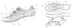
- FIG. 8shows a cycling shoe 800 having features in accordance with one embodiment of the present invention.
- the cycling shoe 800generally comprises an upper portion 802 and an outsole 804 that is lasted to the upper 802 portion using conventional techniques.
- the upper portionhas a system of straps 806 that extend from the outsole 804 and anchor the outsole to the foot.
- the straps 806preferably comprise a synthetic material such as nylon, but may alternatively comprise leather or canvas.
- the straps 806incorporate or are connected to a fastening system 808 , which comprises any of a number of fastener types known in the art, such as a series of straps with hook-and-loop fasteners, or a lace-up system, or some combination thereof.
- An upper fabric 810underlies the straps 806 and preferably comprises a breathable fabric such as a nylon mesh. However, other suitable fabrics known in the art may be used as well.
- the upper portion 802also comprises a heel cage 812 , preferably formed from injection-molded plastic or other strong, durable materials known in the art.
- the heel cage 812provides a strong, resilient connection between the outsole 804 and the upper portion 802 near the heel, and thus promotes efficient power transmission between the foot and the pedal, by preventing the shoe 800 from sliding excessively on the rider's foot while pedaling. Furthermore, the heel cage 812 provides effective power transfer as the rider pulls back and/or up on the pedal during the upstroke.
- reflectors 814may be incorporated into the upper portion 802 as well.
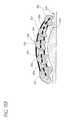
- FIGS. 9A-9Gdepict the outsole 804 in greater detail.
- the outsole 804generally comprises a heel portion 850 , a forefoot portion 852 , and a toe portion 854 ; an upper surface 856 and a lower surface 858 .
- the outsole 804is preferably an integral unit that is molded from nylon and carbon fiber materials, or alternatively a rigid plastic such as ABS or PVC, using known techniques.
- the forefoot portion 852has a pedal contact area 860 with a number of slots and/or openings 862 that facilitate connection of a cleat (not shown) to the outsole 804 .
- pedal contact arearefers to a portion of the outsole can mount a cleat and supports the rider's foot above the pedal; an intervening finish layer (not shown) may be attached to the lower surface 858 of the outsole 804 to provide an aerodynamic lower surface for a road bike shoe, or a tread surface for a mountain-bike shoe, and thus prevent some or all physical contact between the outsole 804 and the pedal surface.
- the forefoot portion 852 and the pedal contact area 860are positioned to underlie the ball of the rider's foot when in use.
- the lateral (i.e. taken at right angles to the longitudinal axis of the outsole 804 ) cross-section of the outsole 804varies in the relative orientation of the upper surface 856 to the horizontal (defined in further detail below).
- the upper surface 856is laterally sloped or tilted with respect to the horizontal, at a varus-compensation angle 864 .
- this upper-surface slope or tiltextends across the substantially the entire width of the upper surface 856 in the forefoot portion 852 and at least part of the toe portion 854 and prevails along the entire pedal contact area 860 .
- this sloped forefoot portiondesirably includes the forward end of the forefoot portion adjacent the toe portion (forward of the location of the metatarsal pad shown in FIG. 11 A).
- the upper surface 852be sloped in substantially the entire area that underlies the ball of the rider's foot when pedaling.
- the slopeis oriented such that the instep or medial portion of the rider's foot is raised slightly from the pedal, as compared to the lateral portion of the foot.
- the varus-compensation angle 864is about 0.5°-6°; preferably the angle is about 1°-4°; most preferably the angle is about 1°-2°.
- the upper surface slopetransitions gradually from the varus-compensation angle 864 in the pedal contact area 860 , forefoot region 852 and/or toe portion 854 to increasingly shallow slopes in the areas adjacent the sloped portion of the upper surface.
- this transition slopemay extend into the heel portion 850 and the toe portion 854 .
- the upper surface 856are substantially parallel to the lower surface 858 .
- FIG. 10shows the orientation of the upper surface 856 with respect to the pedal 502 when the cycling shoe is in use.
- the cleatis not shown and the pedal 502 is shown with a pedal spindle 514 that has a pedal spindle axle 516 .
- the cleat and the lower surface 858 (and/or an intervening finish layer as discussed above) of the outsole 804contact the pedal 502 along or tangent to a base plane 866 , or along or tangent to a number of contact planes oriented parallel to the base plane 866 , depending on the geometry of a particular shoe/cleat/pedal system.
- the base plane 866extends parallel to the pedal spindle axis 516 and is thus always substantially horizontal in the lateral plane (the plane depicted in FIG. 10 ). However, the base plane 866 is not necessarily horizontal in the longitudinal direction (along the length of the cycling shoe, at right angles to the lateral plane), as the pedal and cycling shoe are free to rotate around the pedal spindle 514 while the rider pedals. As used herein, sloping or tilting the upper surface 856 or some other part of the cycling shoe “with respect to the horizontal” means with respect to the horizontal base plane 866 , as opposed to sloping or tilting in the longitudinal direction. Thus, as described herein, parts of the cycling shoe, cleat or pedal that are “horizontal” or “oriented horizontally” are substantially parallel to the base plane 866 , but not necessarily horizontal in the longitudinal direction.
- the lower surface 858 (or other finish layer) of the outsole 804 and/or the cleat contacts the pedal 502the lower surface 858 is thus oriented horizontally, parallel to the pedal spindle axis 514 and the base plane 866 .
- the upper surface 856 of the outsole 804is then sloped with respect to the horizontal by the varus-compensation angle 864 , and provides a sloped bed on which the rider's foot rests or presses (either directly or through an intervening sock liner or insole) while the rider pedals.
- the upper surface 856is sloped with respect to the horizontal along substantially the entire width of the outsole 504 in the forefoot area.
- the upper surface 856is sloped laterally with respect to the horizontal, preferably at a substantially constant varus-compensation angle 864 , throughout the length of the forefoot portion 852 (see FIGS. 9D, 9 G). As discussed above, the sloped orientation of the upper surface 856 promotes the desired, ergonomically proper foot and leg posture for the bicycle rider, and increases power transmission, pedaling efficiency, and rider comfort.
- the design of the cycling shoe 800 as disclosed hereinfacilitates this desired foot/leg posture while providing certain performance advantages as compared to the prior art.
- the outsole 804permits the pedaling force to be transmitted from the foot to the pedal across a broad contact area between the foot and the outsole, and between the outsole and the pedal, thus eliminating pressure concentrations that lead to rider foot discomfort and other deleterious effects.
- the cycling shoe 800permits the cleat to be mounted on the bottom of the outsole 804 such that both sides (medial and lateral) of the lower surface of the cleat are the same, standard distance from the outsole 804 . In the case of a mountain-bike shoe, this feature eliminates the cleat wear and walking discomfort associated with a cleat that lacks sufficient ground clearance and “sticks out” on one or both sides beyond the tread on the bottom of this type of shoe.
- the cycling shoe 800provides the desired angled foot posture in a relatively simple, sturdy shoe design that is relatively easy and inexpensive to manufacture with existing techniques. With no additional mechanisms or moveable parts added to the shoe or pedal, the cycling shoe 800 is lightweight, reliable, and no more complex than needed. The angled position is provided without need for the user to adjust the desired angle and/or periodically check the adjustment, nor is the angle susceptible to falling out of adjustment over time.
- the cycling shoe 800represents an economical solution for a rider, who can obtain the benefits of the angled foot posture without need to purchase a new pedal set for each of his bicycles.
- the cycling shoe 800also permits the design distance between the shoe and the pedal to be maintained, and thus avoids the pedaling efficiency loss observed when the distance between the shoe and the pedal axle is increased.
- the cycling shoe 800is also a quick, easy-to-use solution that addresses the forefoot-varus problems encountered by most of the cycling population. That is, it helps those cyclists who do not have the skill or knowledge to address their performance-robbing varus forefoot. Furthermore, it is a solution for those whose varus is not so severe as to require the intervention of a specialist. With no trouble, investment of time or expertise, and with minimal cost the typical cyclist can use the cycling shoe 800 to address his varus forefoot and increase his cycling performance.
- an important aspect of the present inventionis that a forefoot compensation angle of 1-2 degrees will provide significant benefit to most riders, without creating problems associated with overcompensation. Thus, this aspect brings the advantages heretofore available only for those with sufficient funds or knowledge to the general riding population.
- FIG. 10Adepicts an alternative embodiment 1000 of the cycling shoe, which incorporates some design aspects that make it suitable for use with mountain bikes, but is otherwise similar to the embodiment described above.
- this version of the shoe 1000has a number of tread portions 1002 that extend from the outsole 804 (or a finish layer that covers the outsole 804 ).
- the tread portions 1002facilitate easier footing for the rider when he must dismount the bicycle and walk alongside it.
- FIGS. 11A and 11Bshow an additional feature that is preferably incorporated into the outsole 804 and/or a sockliner laid over the outsole 804 , to enhance rider comfort.
- a metatarsal pad or button 1102may be added, to underlie the lateral arch of the foot 700 (see FIG. 11B) and alleviate the problems associated with “hot foot pain.”
- the metatarsal pad 1102is preferably situated to underlie the second, third and fourth metatarsals 702 rear of the metatarsal heads and assists the lateral arch in maintaining its arch configuration under load. The task of maintaining the arch is thus transferred from the interosseus muscles and ligaments 704 to the metatarsal pad 1102 , significantly relieving hot foot pain.
- the pad 1102has a rounded profile and is 2-4 mm in height.
Landscapes
- Engineering & Computer Science (AREA)
- Chemical & Material Sciences (AREA)
- Combustion & Propulsion (AREA)
- Transportation (AREA)
- Mechanical Engineering (AREA)
- Health & Medical Sciences (AREA)
- General Health & Medical Sciences (AREA)
- Physical Education & Sports Medicine (AREA)
- Footwear And Its Accessory, Manufacturing Method And Apparatuses (AREA)
Abstract
Description
Claims (7)
Priority Applications (2)
| Application Number | Priority Date | Filing Date | Title |
|---|---|---|---|
| US09/552,450US6477793B1 (en) | 2000-04-17 | 2000-04-18 | Cycling shoe |
| PCT/US2001/010934WO2001078541A2 (en) | 2000-04-18 | 2001-04-04 | Cycling shoe |
Applications Claiming Priority (2)
| Application Number | Priority Date | Filing Date | Title |
|---|---|---|---|
| US19789100P | 2000-04-17 | 2000-04-17 | |
| US09/552,450US6477793B1 (en) | 2000-04-17 | 2000-04-18 | Cycling shoe |
Publications (1)
| Publication Number | Publication Date |
|---|---|
| US6477793B1true US6477793B1 (en) | 2002-11-12 |
Family
ID=26893252
Family Applications (1)
| Application Number | Title | Priority Date | Filing Date |
|---|---|---|---|
| US09/552,450Expired - LifetimeUS6477793B1 (en) | 2000-04-17 | 2000-04-18 | Cycling shoe |
Country Status (1)
| Country | Link |
|---|---|
| US (1) | US6477793B1 (en) |
Cited By (94)
| Publication number | Priority date | Publication date | Assignee | Title |
|---|---|---|---|---|
| US20040148809A1 (en)* | 2003-02-03 | 2004-08-05 | Shimano Inc. | Bicycle shoe sole |
| US20050022427A1 (en)* | 2003-07-30 | 2005-02-03 | Mark Kerns | Shoe tightening system |
| US20050284000A1 (en)* | 2004-06-24 | 2005-12-29 | Mark Kerns | Engineered fabric with tightening channels |
| US20060010716A1 (en)* | 2004-07-14 | 2006-01-19 | Dashamerica, Inc. | Composite outsole |
| US20060053664A1 (en)* | 2004-09-15 | 2006-03-16 | Tager Steven E | Orthopedic foot devices |
| US20060059724A1 (en)* | 2002-08-01 | 2006-03-23 | Louis Garneau | Bicycle shoe with ventilating sole |
| US20060143942A1 (en)* | 2005-01-06 | 2006-07-06 | Columbia Insurance Company | Shoe with improved ventilation |
| US20060162190A1 (en)* | 2003-04-24 | 2006-07-27 | Tsuyoshi Nishiwaki | Sports shoes having upper part with improved fitting property |
| US20090293318A1 (en)* | 2008-05-28 | 2009-12-03 | Louis Garneau | Heat moldable sport shoes |
| USD611237S1 (en) | 2009-06-05 | 2010-03-09 | Dashamerica, Inc. | Cycling shoe insole |
| US7752775B2 (en) | 2000-03-10 | 2010-07-13 | Lyden Robert M | Footwear with removable lasting board and cleats |
| US20100192421A1 (en)* | 2004-07-14 | 2010-08-05 | Dashamerica, Inc. D/B/A Pearl Izumi Usa, Inc. | Composite sole |
| US20100263231A1 (en)* | 2009-04-15 | 2010-10-21 | Marie Smirman | Forefoot wedge insert for footwear |
| USD630419S1 (en) | 2009-06-05 | 2011-01-11 | Dashamerica, Inc. | Base plate for adjustable strap |
| US20110023244A1 (en)* | 2009-07-29 | 2011-02-03 | Hogg Stephen J | Functional Fitting Of Cyclists In Clipless Pedal Systems |
| US20110061266A1 (en)* | 2009-09-15 | 2011-03-17 | Homeway Technology Co., Ltd. | Article of footwear that is waterproof, wear-resistant, and lightweight |
| USD636983S1 (en) | 2009-06-05 | 2011-05-03 | Dashamerica, Inc. | Cycling shoe |
| US20110302810A1 (en)* | 2010-06-11 | 2011-12-15 | Salomon S.A.S | Footwear having improved walking comfort |
| US8277401B2 (en) | 2006-09-12 | 2012-10-02 | Boa Technology, Inc. | Closure system for braces, protective wear and similar articles |
| US20120307060A1 (en)* | 2011-06-02 | 2012-12-06 | Neal Henderson | Bicycle Racing Apparatus |
| US8381362B2 (en) | 2004-10-29 | 2013-02-26 | Boa Technology, Inc. | Reel based closure system |
| US8424168B2 (en) | 2008-01-18 | 2013-04-23 | Boa Technology, Inc. | Closure system |
| US8429836B1 (en) | 2010-02-05 | 2013-04-30 | Veronica Tomor | Collapsible athletic shoe |
| US8468657B2 (en) | 2008-11-21 | 2013-06-25 | Boa Technology, Inc. | Reel based lacing system |
| US8479405B2 (en) | 2010-09-30 | 2013-07-09 | Marie Smirman | Measurement system for varus/valgus angles in feet |
| US20130205621A1 (en)* | 2010-06-17 | 2013-08-15 | Dashamerica, Inc. D/B/A Pearl Izumi Usa, Inc. | Bicycling shoe and bicycling shoe components |
| US8516662B2 (en) | 2010-04-30 | 2013-08-27 | Boa Technology, Inc. | Reel based lacing system |
| ES2428214A1 (en)* | 2012-05-03 | 2013-11-06 | Luck Cycling Shoes, S.L. | Sole for cycling shoes (Machine-translation by Google Translate, not legally binding) |
| US20140007461A1 (en)* | 2012-07-09 | 2014-01-09 | Nike, Inc. | Footwear with reflective outsole |
| US8713820B2 (en) | 2010-01-21 | 2014-05-06 | Boa Technology, Inc. | Guides for lacing systems |
| USD709275S1 (en) | 2012-07-25 | 2014-07-22 | Dash American, Inc. | Shoe sole |
| USD710079S1 (en) | 2012-07-25 | 2014-08-05 | Dashamerica, Inc. | Shoe sole |
| USD711083S1 (en) | 2012-07-25 | 2014-08-19 | Dashamerica, Inc. | Shoe sole |
| USD712122S1 (en) | 2012-07-25 | 2014-09-02 | Dash America, Inc. | Shoe sole |
| USD713135S1 (en) | 2012-07-25 | 2014-09-16 | Dashamerica, Inc. | Shoe sole |
| USD715522S1 (en) | 2012-07-25 | 2014-10-21 | Dashamerica, Inc. | Shoe sole |
| US9101181B2 (en) | 2011-10-13 | 2015-08-11 | Boa Technology Inc. | Reel-based lacing system |
| US9149089B2 (en) | 2010-07-01 | 2015-10-06 | Boa Technology, Inc. | Lace guide |
| US9179729B2 (en) | 2012-03-13 | 2015-11-10 | Boa Technology, Inc. | Tightening systems |
| US9237778B2 (en) | 2012-06-25 | 2016-01-19 | Specialized Bicycle Components, Inc. | Cycling shoe |
| US9248040B2 (en) | 2012-08-31 | 2016-02-02 | Boa Technology Inc. | Motorized tensioning system for medical braces and devices |
| USD751281S1 (en) | 2014-08-12 | 2016-03-15 | Boa Technology, Inc. | Footwear tightening reels |
| US9339082B2 (en) | 1997-08-22 | 2016-05-17 | Boa Technology, Inc. | Reel based closure system |
| USD758061S1 (en) | 2014-09-08 | 2016-06-07 | Boa Technology, Inc. | Lace tightening device |
| US9375053B2 (en) | 2012-03-15 | 2016-06-28 | Boa Technology, Inc. | Tightening mechanisms and applications including the same |
| US9414640B2 (en) | 2010-08-02 | 2016-08-16 | Colt Carter Nichols | Cycling shoe |
| US9439477B2 (en) | 2013-01-28 | 2016-09-13 | Boa Technology Inc. | Lace fixation assembly and system |
| USD767269S1 (en) | 2014-08-26 | 2016-09-27 | Boa Technology Inc. | Footwear tightening reel |
| US9516923B2 (en) | 2012-11-02 | 2016-12-13 | Boa Technology Inc. | Coupling members for closure devices and systems |
| US9532626B2 (en) | 2013-04-01 | 2017-01-03 | Boa Technology, Inc. | Methods and devices for retrofitting footwear to include a reel based closure system |
| USD776421S1 (en) | 2015-01-16 | 2017-01-17 | Boa Technology, Inc. | In-footwear lace tightening reel |
| US9610185B2 (en) | 2013-03-05 | 2017-04-04 | Boa Technology Inc. | Systems, methods, and devices for automatic closure of medical devices |
| US9629417B2 (en) | 2013-07-02 | 2017-04-25 | Boa Technology Inc. | Tension limiting mechanisms for closure devices and methods therefor |
| US9681705B2 (en) | 2013-09-13 | 2017-06-20 | Boa Technology Inc. | Failure compensating lace tension devices and methods |
| US9700101B2 (en) | 2013-09-05 | 2017-07-11 | Boa Technology Inc. | Guides and components for closure systems and methods therefor |
| US9706814B2 (en) | 2013-07-10 | 2017-07-18 | Boa Technology Inc. | Closure devices including incremental release mechanisms and methods therefor |
| US9737115B2 (en) | 2012-11-06 | 2017-08-22 | Boa Technology Inc. | Devices and methods for adjusting the fit of footwear |
| US9770070B2 (en) | 2013-06-05 | 2017-09-26 | Boa Technology Inc. | Integrated closure device components and methods |
| US9872790B2 (en) | 2013-11-18 | 2018-01-23 | Boa Technology Inc. | Methods and devices for providing automatic closure of prosthetics and orthotics |
| US9918865B2 (en) | 2010-07-01 | 2018-03-20 | 3M Innovative Properties Company | Braces using lacing systems |
| US20180146741A1 (en)* | 2014-09-20 | 2018-05-31 | Christopher Martin | Improved bicycle shoe to pedal cleat shim and mounting |
| US20180160764A1 (en)* | 2016-12-12 | 2018-06-14 | Louis Garneau Sports Inc | Cycling shoe with lateral metatarsal expansion zone |
| US10070695B2 (en) | 2010-04-30 | 2018-09-11 | Boa Technology Inc. | Tightening mechanisms and applications including the same |
| US10076160B2 (en) | 2013-06-05 | 2018-09-18 | Boa Technology Inc. | Integrated closure device components and methods |
| USD835898S1 (en) | 2015-01-16 | 2018-12-18 | Boa Technology Inc. | Footwear lace tightening reel stabilizer |
| USD835976S1 (en) | 2014-01-16 | 2018-12-18 | Boa Technology Inc. | Coupling member |
| US10182935B2 (en) | 2014-10-01 | 2019-01-22 | Ossur Hf | Support for articles and methods for using the same |
| US20190069627A1 (en)* | 2010-06-17 | 2019-03-07 | Dashamerica, Inc. D/B/A Pearl Izumi Usa, Inc. | Dual rigidity shoe sole |
| IT201700100645A1 (en)* | 2017-09-08 | 2019-03-08 | Northwave S R L | SOLE FOR CYCLING SHOES |
| US10251451B2 (en) | 2013-03-05 | 2019-04-09 | Boa Technology Inc. | Closure devices including incremental release mechanisms and methods therefor |
| US10405601B2 (en)* | 2017-09-07 | 2019-09-10 | Trek Bicycle Corporation | Cycling shoe |
| US10492568B2 (en) | 2014-08-28 | 2019-12-03 | Boa Technology Inc. | Devices and methods for tensioning apparel and other items |
| US10499709B2 (en) | 2016-08-02 | 2019-12-10 | Boa Technology Inc. | Tension member guides of a lacing system |
| US10543630B2 (en) | 2017-02-27 | 2020-01-28 | Boa Technology Inc. | Reel based closure system employing a friction based tension mechanism |
| US10575591B2 (en) | 2014-10-07 | 2020-03-03 | Boa Technology Inc. | Devices, methods, and systems for remote control of a motorized closure system |
| US10660399B2 (en) | 2011-03-25 | 2020-05-26 | Dashamerica, Inc. | Flexible shoe sole |
| US10702409B2 (en) | 2013-02-05 | 2020-07-07 | Boa Technology Inc. | Closure devices for medical devices and methods |
| US10772384B2 (en) | 2017-07-18 | 2020-09-15 | Boa Technology Inc. | System and methods for minimizing dynamic lace movement |
| US10791798B2 (en) | 2015-10-15 | 2020-10-06 | Boa Technology Inc. | Lacing configurations for footwear |
| US10842230B2 (en) | 2016-12-09 | 2020-11-24 | Boa Technology Inc. | Reel based closure system |
| US11291266B2 (en) | 2012-07-06 | 2022-04-05 | Specialized Bicycle Components, Inc. | Cycling shoe |
| US11357279B2 (en) | 2017-05-09 | 2022-06-14 | Boa Technology Inc. | Closure components for a helmet layer and methods for installing same |
| US11492228B2 (en) | 2019-05-01 | 2022-11-08 | Boa Technology Inc. | Reel based closure system |
| USD974005S1 (en) | 2020-12-23 | 2023-01-03 | Specialized Bicycle Components, Inc. | Shoe |
| USD975405S1 (en) | 2021-01-14 | 2023-01-17 | Specialized Bicycle Components, Inc. | Shoe |
| USD975970S1 (en) | 2020-12-23 | 2023-01-24 | Specialized Bicycle Components, Inc. | Shoe |
| USD975969S1 (en) | 2020-10-27 | 2023-01-24 | Specialized Bicycle Components, Inc. | Shoe |
| USD980609S1 (en) | 2020-07-31 | 2023-03-14 | Specialized Bicycle Components, Inc. | Bicycle shoe |
| US20230320457A1 (en)* | 2020-08-21 | 2023-10-12 | The Regents Of The University Of Colorado, A Body Corporate | Dual purpose running and cycling shoe |
| USD1030260S1 (en) | 2021-09-27 | 2024-06-11 | Specialized Bicycle Components, Inc. | Shoe |
| USD1050685S1 (en) | 2021-10-15 | 2024-11-12 | Specialized Bicycle Components, Inc. | Shoe |
| USD1052853S1 (en) | 2021-12-06 | 2024-12-03 | Specialized Bicycle Components, Inc. | Shoe |
| US12256803B2 (en) | 2019-02-01 | 2025-03-25 | Boa Technology Inc. | Reel based closure devices for tightening a ski boot |
| US12396520B2 (en) | 2017-07-18 | 2025-08-26 | Boa Technology Inc. | Configurations for footwear employing reel based closure systems |
Citations (16)
| Publication number | Priority date | Publication date | Assignee | Title |
|---|---|---|---|---|
| US2052115A (en)* | 1935-03-18 | 1936-08-25 | Shulman Maurice Harold | Outer sole for boots and shoes |
| US2616190A (en)* | 1946-06-14 | 1952-11-04 | Reuben U Darby | Walking angle corrective footwear |
| US4255877A (en)* | 1978-09-25 | 1981-03-17 | Brs, Inc. | Athletic shoe having external heel counter |
| FR2464660A1 (en) | 1979-09-10 | 1981-03-20 | Camuset | LEATHER PEDAL DEVICE FOR CYCLING SHOE |
| US4266553A (en)* | 1979-10-22 | 1981-05-12 | Faiella Joseph V | Footgear embodying podiatric sole |
| US4287675A (en)* | 1980-01-17 | 1981-09-08 | New Balance Athletic Shoe, Inc. | Counter for athletic shoe |
| US4578882A (en)* | 1984-07-31 | 1986-04-01 | Talarico Ii Louis C | Forefoot compensated footwear |
| US4620376A (en)* | 1985-01-22 | 1986-11-04 | Talarico Ii Louis C | Forefoot valgus compensated footwear |
| US4754561A (en)* | 1986-05-09 | 1988-07-05 | Salomon S.A. | Golf shoe |
| FR2620412A1 (en) | 1987-09-10 | 1989-03-17 | Manoel Bouchet | PEDAL ASSEMBLY FOR BICYCLE |
| FR2620909A1 (en) | 1987-09-28 | 1989-03-31 | Salomon Sa | SKI SHOE SOLE |
| US4907355A (en)* | 1988-07-18 | 1990-03-13 | Nike, Inc | Cycling shoe with adjustable cleat system |
| US5086576A (en)* | 1990-05-29 | 1992-02-11 | Lamson Donald W | Bicycle shoe |
| WO1992016374A1 (en) | 1991-03-15 | 1992-10-01 | Eastman Kodak Company | Focus fiber mount |
| US5822889A (en)* | 1995-02-10 | 1998-10-20 | Shimano, Inc. | Bicycles shoes |
| US6189242B1 (en)* | 1999-11-29 | 2001-02-20 | Mikel Lin | Shoe for bicycle |
- 2000
- 2000-04-18USUS09/552,450patent/US6477793B1/ennot_activeExpired - Lifetime
Patent Citations (16)
| Publication number | Priority date | Publication date | Assignee | Title |
|---|---|---|---|---|
| US2052115A (en)* | 1935-03-18 | 1936-08-25 | Shulman Maurice Harold | Outer sole for boots and shoes |
| US2616190A (en)* | 1946-06-14 | 1952-11-04 | Reuben U Darby | Walking angle corrective footwear |
| US4255877A (en)* | 1978-09-25 | 1981-03-17 | Brs, Inc. | Athletic shoe having external heel counter |
| FR2464660A1 (en) | 1979-09-10 | 1981-03-20 | Camuset | LEATHER PEDAL DEVICE FOR CYCLING SHOE |
| US4266553A (en)* | 1979-10-22 | 1981-05-12 | Faiella Joseph V | Footgear embodying podiatric sole |
| US4287675A (en)* | 1980-01-17 | 1981-09-08 | New Balance Athletic Shoe, Inc. | Counter for athletic shoe |
| US4578882A (en)* | 1984-07-31 | 1986-04-01 | Talarico Ii Louis C | Forefoot compensated footwear |
| US4620376A (en)* | 1985-01-22 | 1986-11-04 | Talarico Ii Louis C | Forefoot valgus compensated footwear |
| US4754561A (en)* | 1986-05-09 | 1988-07-05 | Salomon S.A. | Golf shoe |
| FR2620412A1 (en) | 1987-09-10 | 1989-03-17 | Manoel Bouchet | PEDAL ASSEMBLY FOR BICYCLE |
| FR2620909A1 (en) | 1987-09-28 | 1989-03-31 | Salomon Sa | SKI SHOE SOLE |
| US4907355A (en)* | 1988-07-18 | 1990-03-13 | Nike, Inc | Cycling shoe with adjustable cleat system |
| US5086576A (en)* | 1990-05-29 | 1992-02-11 | Lamson Donald W | Bicycle shoe |
| WO1992016374A1 (en) | 1991-03-15 | 1992-10-01 | Eastman Kodak Company | Focus fiber mount |
| US5822889A (en)* | 1995-02-10 | 1998-10-20 | Shimano, Inc. | Bicycles shoes |
| US6189242B1 (en)* | 1999-11-29 | 2001-02-20 | Mikel Lin | Shoe for bicycle |
Cited By (155)
| Publication number | Priority date | Publication date | Assignee | Title |
|---|---|---|---|---|
| US9743714B2 (en) | 1997-08-22 | 2017-08-29 | Boa Technology Inc. | Reel based closure system |
| US9339082B2 (en) | 1997-08-22 | 2016-05-17 | Boa Technology, Inc. | Reel based closure system |
| US10362836B2 (en) | 1997-08-22 | 2019-07-30 | Boa Technology Inc. | Reel based closure system |
| US8209883B2 (en) | 2000-03-10 | 2012-07-03 | Robert Michael Lyden | Custom article of footwear and method of making the same |
| US7770306B2 (en) | 2000-03-10 | 2010-08-10 | Lyden Robert M | Custom article of footwear |
| US7752775B2 (en) | 2000-03-10 | 2010-07-13 | Lyden Robert M | Footwear with removable lasting board and cleats |
| US20060059724A1 (en)* | 2002-08-01 | 2006-03-23 | Louis Garneau | Bicycle shoe with ventilating sole |
| US7533475B2 (en) | 2002-08-01 | 2009-05-19 | Louis Garneau Sports Inc. | Bicycle shoe with ventilating sole |
| US7707750B2 (en) | 2002-08-01 | 2010-05-04 | Louis Garneau Sports Inc. | Bicycle shoe with ventilating sole |
| US20090139112A1 (en)* | 2002-08-01 | 2009-06-04 | Louis Garneau | Bicycle shoe with ventilating sole |
| US20040148809A1 (en)* | 2003-02-03 | 2004-08-05 | Shimano Inc. | Bicycle shoe sole |
| US8713821B2 (en) | 2003-04-24 | 2014-05-06 | Asics Corporation | Athletic shoes having an upper whose fitting property is improved |
| US7823298B2 (en) | 2003-04-24 | 2010-11-02 | Asics Corporation | Athletic shoes having an upper whose fitting property is improved |
| US20060162190A1 (en)* | 2003-04-24 | 2006-07-27 | Tsuyoshi Nishiwaki | Sports shoes having upper part with improved fitting property |
| US20110041362A1 (en)* | 2003-04-24 | 2011-02-24 | Tsuyoshi Nishiwaki | Athletic Shoes Having an Upper Whose Fitting Property is Improved |
| US10849390B2 (en) | 2003-06-12 | 2020-12-01 | Boa Technology Inc. | Reel based closure system |
| US9867430B2 (en) | 2003-06-12 | 2018-01-16 | Boa Technology Inc. | Reel based closure system |
| US20050022427A1 (en)* | 2003-07-30 | 2005-02-03 | Mark Kerns | Shoe tightening system |
| US6922917B2 (en) | 2003-07-30 | 2005-08-02 | Dashamerica, Inc. | Shoe tightening system |
| US20050198866A1 (en)* | 2003-07-30 | 2005-09-15 | Anne Wiper | Shoe tightening system |
| US20050284000A1 (en)* | 2004-06-24 | 2005-12-29 | Mark Kerns | Engineered fabric with tightening channels |
| US7568298B2 (en) | 2004-06-24 | 2009-08-04 | Dashamerica, Inc. | Engineered fabric with tightening channels |
| US20100192421A1 (en)* | 2004-07-14 | 2010-08-05 | Dashamerica, Inc. D/B/A Pearl Izumi Usa, Inc. | Composite sole |
| US7401424B2 (en) | 2004-07-14 | 2008-07-22 | Dashamerica, Inc. | Composite outsole |
| US20060010716A1 (en)* | 2004-07-14 | 2006-01-19 | Dashamerica, Inc. | Composite outsole |
| US7299568B2 (en) | 2004-09-15 | 2007-11-27 | Tager Steven E | Orthopedic foot devices |
| US20060053664A1 (en)* | 2004-09-15 | 2006-03-16 | Tager Steven E | Orthopedic foot devices |
| US8381362B2 (en) | 2004-10-29 | 2013-02-26 | Boa Technology, Inc. | Reel based closure system |
| US10952505B2 (en) | 2004-10-29 | 2021-03-23 | Boa Technology Inc. | Reel based closure system |
| US20060143942A1 (en)* | 2005-01-06 | 2006-07-06 | Columbia Insurance Company | Shoe with improved ventilation |
| US7328524B2 (en) | 2005-01-06 | 2008-02-12 | Columbia Insurance Company | Shoe with improved ventilation |
| US10433999B2 (en) | 2006-09-12 | 2019-10-08 | Boa Technology, Inc. | Closure system for braces, protective wear and similar articles |
| US11877943B2 (en) | 2006-09-12 | 2024-01-23 | Boa Technology, Inc. | Closure system for braces, protective wear and similar articles |
| US8277401B2 (en) | 2006-09-12 | 2012-10-02 | Boa Technology, Inc. | Closure system for braces, protective wear and similar articles |
| US8424168B2 (en) | 2008-01-18 | 2013-04-23 | Boa Technology, Inc. | Closure system |
| US8984719B2 (en) | 2008-01-18 | 2015-03-24 | Boa Technology, Inc. | Closure system |
| US20090293318A1 (en)* | 2008-05-28 | 2009-12-03 | Louis Garneau | Heat moldable sport shoes |
| US10863796B2 (en) | 2008-11-21 | 2020-12-15 | Boa Technology, Inc. | Reel based lacing system |
| US10123589B2 (en) | 2008-11-21 | 2018-11-13 | Boa Technology, Inc. | Reel based lacing system |
| US8468657B2 (en) | 2008-11-21 | 2013-06-25 | Boa Technology, Inc. | Reel based lacing system |
| US11779083B2 (en) | 2008-11-21 | 2023-10-10 | Boa Technology, Inc. | Reel based lacing system |
| US20150047226A1 (en)* | 2009-04-15 | 2015-02-19 | Marie Smirman | Forefoot wedge insert for footwear |
| US20100263231A1 (en)* | 2009-04-15 | 2010-10-21 | Marie Smirman | Forefoot wedge insert for footwear |
| US20100263230A1 (en)* | 2009-04-15 | 2010-10-21 | Marie Smirman | Insert for rockered foot bed of footwear |
| US8523194B2 (en) | 2009-04-15 | 2013-09-03 | Marie Smirman | Forefoot wedge insert for footwear |
| US20100263232A1 (en)* | 2009-04-15 | 2010-10-21 | Marie Smirman | Moldable arch support for footwear |
| USD636983S1 (en) | 2009-06-05 | 2011-05-03 | Dashamerica, Inc. | Cycling shoe |
| USD630419S1 (en) | 2009-06-05 | 2011-01-11 | Dashamerica, Inc. | Base plate for adjustable strap |
| USD611237S1 (en) | 2009-06-05 | 2010-03-09 | Dashamerica, Inc. | Cycling shoe insole |
| USD645652S1 (en) | 2009-06-05 | 2011-09-27 | Dashamerica, Inc. | Cycling shoe |
| US20110023244A1 (en)* | 2009-07-29 | 2011-02-03 | Hogg Stephen J | Functional Fitting Of Cyclists In Clipless Pedal Systems |
| US8196243B2 (en)* | 2009-07-29 | 2012-06-12 | Pedal Pushers Cycles Pty Ltd | Functional fitting of cyclists in clipless pedal systems |
| US20110061266A1 (en)* | 2009-09-15 | 2011-03-17 | Homeway Technology Co., Ltd. | Article of footwear that is waterproof, wear-resistant, and lightweight |
| US8713820B2 (en) | 2010-01-21 | 2014-05-06 | Boa Technology, Inc. | Guides for lacing systems |
| US9125455B2 (en) | 2010-01-21 | 2015-09-08 | Boa Technology Inc. | Guides for lacing systems |
| US9854873B2 (en) | 2010-01-21 | 2018-01-02 | Boa Technology Inc. | Guides for lacing systems |
| US8429836B1 (en) | 2010-02-05 | 2013-04-30 | Veronica Tomor | Collapsible athletic shoe |
| US10888139B2 (en) | 2010-04-30 | 2021-01-12 | Boa Technology Inc. | Tightening mechanisms and applications including same |
| US8516662B2 (en) | 2010-04-30 | 2013-08-27 | Boa Technology, Inc. | Reel based lacing system |
| US9408437B2 (en) | 2010-04-30 | 2016-08-09 | Boa Technology, Inc. | Reel based lacing system |
| US10070695B2 (en) | 2010-04-30 | 2018-09-11 | Boa Technology Inc. | Tightening mechanisms and applications including the same |
| US20110302810A1 (en)* | 2010-06-11 | 2011-12-15 | Salomon S.A.S | Footwear having improved walking comfort |
| US20130205621A1 (en)* | 2010-06-17 | 2013-08-15 | Dashamerica, Inc. D/B/A Pearl Izumi Usa, Inc. | Bicycling shoe and bicycling shoe components |
| US20190069627A1 (en)* | 2010-06-17 | 2019-03-07 | Dashamerica, Inc. D/B/A Pearl Izumi Usa, Inc. | Dual rigidity shoe sole |
| US8826570B2 (en) | 2010-06-17 | 2014-09-09 | Dashamerica, Inc. | Bicycling shoe and bicycling shoe components |
| US11272756B2 (en)* | 2010-06-17 | 2022-03-15 | Dashamerica, Inc. | Dual rigidity shoe sole |
| US8763279B2 (en)* | 2010-06-17 | 2014-07-01 | Dashamerica, Inc. | Bicycling shoe and bicycling shoe components |
| US9918865B2 (en) | 2010-07-01 | 2018-03-20 | 3M Innovative Properties Company | Braces using lacing systems |
| US9149089B2 (en) | 2010-07-01 | 2015-10-06 | Boa Technology, Inc. | Lace guide |
| US9414640B2 (en) | 2010-08-02 | 2016-08-16 | Colt Carter Nichols | Cycling shoe |
| US8479405B2 (en) | 2010-09-30 | 2013-07-09 | Marie Smirman | Measurement system for varus/valgus angles in feet |
| US10660399B2 (en) | 2011-03-25 | 2020-05-26 | Dashamerica, Inc. | Flexible shoe sole |
| US20120307060A1 (en)* | 2011-06-02 | 2012-12-06 | Neal Henderson | Bicycle Racing Apparatus |
| US10413019B2 (en) | 2011-10-13 | 2019-09-17 | Boa Technology Inc | Reel-based lacing system |
| US11297903B2 (en) | 2011-10-13 | 2022-04-12 | Boa Technology, Inc. | Reel-based lacing system |
| US9101181B2 (en) | 2011-10-13 | 2015-08-11 | Boa Technology Inc. | Reel-based lacing system |
| US9179729B2 (en) | 2012-03-13 | 2015-11-10 | Boa Technology, Inc. | Tightening systems |
| US9375053B2 (en) | 2012-03-15 | 2016-06-28 | Boa Technology, Inc. | Tightening mechanisms and applications including the same |
| ES2428214A1 (en)* | 2012-05-03 | 2013-11-06 | Luck Cycling Shoes, S.L. | Sole for cycling shoes (Machine-translation by Google Translate, not legally binding) |
| US9237778B2 (en) | 2012-06-25 | 2016-01-19 | Specialized Bicycle Components, Inc. | Cycling shoe |
| US11291266B2 (en) | 2012-07-06 | 2022-04-05 | Specialized Bicycle Components, Inc. | Cycling shoe |
| US20140007461A1 (en)* | 2012-07-09 | 2014-01-09 | Nike, Inc. | Footwear with reflective outsole |
| US10028550B2 (en)* | 2012-07-09 | 2018-07-24 | Nike, Inc. | Footwear with reflective outsole |
| USD710079S1 (en) | 2012-07-25 | 2014-08-05 | Dashamerica, Inc. | Shoe sole |
| USD711083S1 (en) | 2012-07-25 | 2014-08-19 | Dashamerica, Inc. | Shoe sole |
| USD712122S1 (en) | 2012-07-25 | 2014-09-02 | Dash America, Inc. | Shoe sole |
| USD715522S1 (en) | 2012-07-25 | 2014-10-21 | Dashamerica, Inc. | Shoe sole |
| USD713135S1 (en) | 2012-07-25 | 2014-09-16 | Dashamerica, Inc. | Shoe sole |
| USD709275S1 (en) | 2012-07-25 | 2014-07-22 | Dash American, Inc. | Shoe sole |
| US9248040B2 (en) | 2012-08-31 | 2016-02-02 | Boa Technology Inc. | Motorized tensioning system for medical braces and devices |
| US9516923B2 (en) | 2012-11-02 | 2016-12-13 | Boa Technology Inc. | Coupling members for closure devices and systems |
| US9737115B2 (en) | 2012-11-06 | 2017-08-22 | Boa Technology Inc. | Devices and methods for adjusting the fit of footwear |
| US10327513B2 (en) | 2012-11-06 | 2019-06-25 | Boa Technology Inc. | Devices and methods for adjusting the fit of footwear |
| USRE48215E1 (en) | 2013-01-28 | 2020-09-22 | Boa Technology Inc. | Lace fixation assembly and system |
| USRE49092E1 (en) | 2013-01-28 | 2022-06-07 | Boa Technology Inc. | Lace fixation assembly and system |
| USRE49358E1 (en) | 2013-01-28 | 2023-01-10 | Boa Technology, Inc. | Lace fixation assembly and system |
| US9439477B2 (en) | 2013-01-28 | 2016-09-13 | Boa Technology Inc. | Lace fixation assembly and system |
| US10702409B2 (en) | 2013-02-05 | 2020-07-07 | Boa Technology Inc. | Closure devices for medical devices and methods |
| US10251451B2 (en) | 2013-03-05 | 2019-04-09 | Boa Technology Inc. | Closure devices including incremental release mechanisms and methods therefor |
| US10959492B2 (en) | 2013-03-05 | 2021-03-30 | Boa Technology Inc. | Closure devices including incremental release mechanisms and methods therefor |
| US9610185B2 (en) | 2013-03-05 | 2017-04-04 | Boa Technology Inc. | Systems, methods, and devices for automatic closure of medical devices |
| US9532626B2 (en) | 2013-04-01 | 2017-01-03 | Boa Technology, Inc. | Methods and devices for retrofitting footwear to include a reel based closure system |
| US10342294B2 (en) | 2013-04-01 | 2019-07-09 | Boa Technology Inc. | Methods and devices for retrofitting footwear to include a reel based closure system |
| US9770070B2 (en) | 2013-06-05 | 2017-09-26 | Boa Technology Inc. | Integrated closure device components and methods |
| US12144401B2 (en) | 2013-06-05 | 2024-11-19 | Boa Technology, Inc. | Integrated closure device components and methods |
| US10772388B2 (en) | 2013-06-05 | 2020-09-15 | Boa Technology Inc. | Integrated closure device components and methods |
| US10076160B2 (en) | 2013-06-05 | 2018-09-18 | Boa Technology Inc. | Integrated closure device components and methods |
| US9629417B2 (en) | 2013-07-02 | 2017-04-25 | Boa Technology Inc. | Tension limiting mechanisms for closure devices and methods therefor |
| US10039348B2 (en) | 2013-07-02 | 2018-08-07 | Boa Technology Inc. | Tension limiting mechanisms for closure devices and methods therefor |
| US9706814B2 (en) | 2013-07-10 | 2017-07-18 | Boa Technology Inc. | Closure devices including incremental release mechanisms and methods therefor |
| US11253028B2 (en) | 2013-09-05 | 2022-02-22 | Boa Technology Inc. | Guides and components for closure systems and methods therefor |
| US9700101B2 (en) | 2013-09-05 | 2017-07-11 | Boa Technology Inc. | Guides and components for closure systems and methods therefor |
| US10477922B2 (en) | 2013-09-05 | 2019-11-19 | Boa Technology Inc. | Guides and components for closure systems and methods therefor |
| US10952503B2 (en) | 2013-09-13 | 2021-03-23 | Boa Technology Inc. | Failure compensating lace tension devices and methods |
| US9681705B2 (en) | 2013-09-13 | 2017-06-20 | Boa Technology Inc. | Failure compensating lace tension devices and methods |
| US9872790B2 (en) | 2013-11-18 | 2018-01-23 | Boa Technology Inc. | Methods and devices for providing automatic closure of prosthetics and orthotics |
| USD835976S1 (en) | 2014-01-16 | 2018-12-18 | Boa Technology Inc. | Coupling member |
| USD751281S1 (en) | 2014-08-12 | 2016-03-15 | Boa Technology, Inc. | Footwear tightening reels |
| USD767269S1 (en) | 2014-08-26 | 2016-09-27 | Boa Technology Inc. | Footwear tightening reel |
| US10492568B2 (en) | 2014-08-28 | 2019-12-03 | Boa Technology Inc. | Devices and methods for tensioning apparel and other items |
| USD758061S1 (en) | 2014-09-08 | 2016-06-07 | Boa Technology, Inc. | Lace tightening device |
| US10517349B2 (en)* | 2014-09-20 | 2019-12-31 | Christopher Martin | Bicycle shoe to pedal cleat shim and mounting |
| US20180146741A1 (en)* | 2014-09-20 | 2018-05-31 | Christopher Martin | Improved bicycle shoe to pedal cleat shim and mounting |
| US12251327B2 (en) | 2014-10-01 | 2025-03-18 | Ossur Hr | Support for articles and methods for using the same |
| US11304838B2 (en) | 2014-10-01 | 2022-04-19 | Ossur Hf | Support for articles and methods for using the same |
| US10182935B2 (en) | 2014-10-01 | 2019-01-22 | Ossur Hf | Support for articles and methods for using the same |
| US10575591B2 (en) | 2014-10-07 | 2020-03-03 | Boa Technology Inc. | Devices, methods, and systems for remote control of a motorized closure system |
| USD835898S1 (en) | 2015-01-16 | 2018-12-18 | Boa Technology Inc. | Footwear lace tightening reel stabilizer |
| USD776421S1 (en) | 2015-01-16 | 2017-01-17 | Boa Technology, Inc. | In-footwear lace tightening reel |
| US10791798B2 (en) | 2015-10-15 | 2020-10-06 | Boa Technology Inc. | Lacing configurations for footwear |
| US10499709B2 (en) | 2016-08-02 | 2019-12-10 | Boa Technology Inc. | Tension member guides of a lacing system |
| US11089837B2 (en) | 2016-08-02 | 2021-08-17 | Boa Technology Inc. | Tension member guides for lacing systems |
| US10842230B2 (en) | 2016-12-09 | 2020-11-24 | Boa Technology Inc. | Reel based closure system |
| US11503873B2 (en)* | 2016-12-12 | 2022-11-22 | Louis Garneau Sports Inc | Cycling shoe with lateral metatarsal expansion zone |
| US20180160764A1 (en)* | 2016-12-12 | 2018-06-14 | Louis Garneau Sports Inc | Cycling shoe with lateral metatarsal expansion zone |
| US10543630B2 (en) | 2017-02-27 | 2020-01-28 | Boa Technology Inc. | Reel based closure system employing a friction based tension mechanism |
| US11220030B2 (en) | 2017-02-27 | 2022-01-11 | Boa Technology Inc. | Reel based closure system employing a friction based tension mechanism |
| US11357279B2 (en) | 2017-05-09 | 2022-06-14 | Boa Technology Inc. | Closure components for a helmet layer and methods for installing same |
| US12396520B2 (en) | 2017-07-18 | 2025-08-26 | Boa Technology Inc. | Configurations for footwear employing reel based closure systems |
| US10772384B2 (en) | 2017-07-18 | 2020-09-15 | Boa Technology Inc. | System and methods for minimizing dynamic lace movement |
| US10405601B2 (en)* | 2017-09-07 | 2019-09-10 | Trek Bicycle Corporation | Cycling shoe |
| IT201700100645A1 (en)* | 2017-09-08 | 2019-03-08 | Northwave S R L | SOLE FOR CYCLING SHOES |
| WO2019048105A1 (en)* | 2017-09-08 | 2019-03-14 | Northwave S.R.L. | Sole for a cycling shoe |
| US12256803B2 (en) | 2019-02-01 | 2025-03-25 | Boa Technology Inc. | Reel based closure devices for tightening a ski boot |
| US11492228B2 (en) | 2019-05-01 | 2022-11-08 | Boa Technology Inc. | Reel based closure system |
| USD980609S1 (en) | 2020-07-31 | 2023-03-14 | Specialized Bicycle Components, Inc. | Bicycle shoe |
| US20230320457A1 (en)* | 2020-08-21 | 2023-10-12 | The Regents Of The University Of Colorado, A Body Corporate | Dual purpose running and cycling shoe |
| USD975969S1 (en) | 2020-10-27 | 2023-01-24 | Specialized Bicycle Components, Inc. | Shoe |
| USD975970S1 (en) | 2020-12-23 | 2023-01-24 | Specialized Bicycle Components, Inc. | Shoe |
| USD1076352S1 (en) | 2020-12-23 | 2025-05-27 | Specialized Bicycle Components, Inc. | Shoe |
| USD974005S1 (en) | 2020-12-23 | 2023-01-03 | Specialized Bicycle Components, Inc. | Shoe |
| USD975405S1 (en) | 2021-01-14 | 2023-01-17 | Specialized Bicycle Components, Inc. | Shoe |
| USD1030260S1 (en) | 2021-09-27 | 2024-06-11 | Specialized Bicycle Components, Inc. | Shoe |
| USD1050685S1 (en) | 2021-10-15 | 2024-11-12 | Specialized Bicycle Components, Inc. | Shoe |
| USD1052853S1 (en) | 2021-12-06 | 2024-12-03 | Specialized Bicycle Components, Inc. | Shoe |
Similar Documents
| Publication | Publication Date | Title |
|---|---|---|
| US6477793B1 (en) | Cycling shoe | |
| CN1149028C (en) | Shoe pad for correcting, regulating and relaxing foot bottom | |
| US4574498A (en) | Sole for athletic shoe | |
| US7266912B2 (en) | Exercise sole | |
| US4620376A (en) | Forefoot valgus compensated footwear | |
| US6887213B2 (en) | Ankle-foot orthosis | |
| CN1163166C (en) | High-heeled shoes and manufacturing method thereof | |
| US6272773B1 (en) | Riding shoe | |
| US20080155856A1 (en) | Sandal strap system | |
| JPS6213001B2 (en) | ||
| US5860330A (en) | Device for holding one's foot at an angle | |
| EP1121181A1 (en) | Double hinged skate | |
| FR2736516B1 (en) | FOOTWEAR FOR THE PRACTICE OF A SLIDING SPORT | |
| WO2001078541A2 (en) | Cycling shoe | |
| CA1205626A (en) | Athletic shoe for field sports | |
| US5400527A (en) | Biomechanical ski boot with resilient elements in the sole | |
| US20150264998A1 (en) | Sole structure for biomechanical control | |
| US20030014881A1 (en) | Foot guided shoe sole and footbed | |
| US7360326B1 (en) | Flexible footwear sole | |
| CA2161832C (en) | Forefoot relieving shoe, more particularly for postoperative treatment | |
| US20130055592A1 (en) | Shoe insert and shoe | |
| GB2437698A (en) | Heelless footwear | |
| US20210195987A1 (en) | Adjustable flex footwear system | |
| WO2006005139A1 (en) | A shoe | |
| CN221532988U (en) | Shock-absorbing riding sole and shoes |
Legal Events
| Date | Code | Title | Description |
|---|---|---|---|
| AS | Assignment | Owner name:SPECIALIZED BICYCLE COMPONENTS, INC., CALIFORNIA Free format text:ASSIGNMENT OF ASSIGNORS INTEREST;ASSIGNORS:PRUITT, DR. ANDREW L.;BIRD, CARL;FRYER, LUKE;REEL/FRAME:011015/0568;SIGNING DATES FROM 20000613 TO 20000616 | |
| AS | Assignment | Owner name:BANK OF AMERICA, N.A., AS ADMINISTRATIVE AGENT, WA Free format text:SECURITY AGREEMENT;ASSIGNOR:SPECIALIZED BICYCLE COMPONENTS, INC.;REEL/FRAME:011122/0873 Effective date:20000401 | |
| AS | Assignment | Owner name:SPECIALIZED BICYCLE COMPONENTS, INC., CALIFORNIA Free format text:RELEASE OF SECURITY INTEREST;ASSIGNOR:BANK OF AMERICA, N.A., AS ADMINISTRATIVE AGENT;REEL/FRAME:011944/0596 Effective date:20010629 Owner name:GENERAL ELECTRIC CAPITAL CORPORATION, AS ADMINISTR Free format text:MERGER;ASSIGNOR:SPECIALIZED BICYCLE COMPONENTS, INC.;REEL/FRAME:012025/0488 Effective date:20010629 | |
| STCF | Information on status: patent grant | Free format text:PATENTED CASE | |
| CC | Certificate of correction | ||
| FPAY | Fee payment | Year of fee payment:4 | |
| SULP | Surcharge for late payment | ||
| FPAY | Fee payment | Year of fee payment:8 | |
| FPAY | Fee payment | Year of fee payment:12 |