US6477425B1 - External transmitter for implanted medical device - Google Patents
External transmitter for implanted medical deviceDownload PDFInfo
- Publication number
- US6477425B1 US6477425B1US09/472,071US47207199AUS6477425B1US 6477425 B1US6477425 B1US 6477425B1US 47207199 AUS47207199 AUS 47207199AUS 6477425 B1US6477425 B1US 6477425B1
- Authority
- US
- United States
- Prior art keywords
- battery
- power
- amplifier
- fpga
- power supply
- Prior art date
- Legal status (The legal status is an assumption and is not a legal conclusion. Google has not performed a legal analysis and makes no representation as to the accuracy of the status listed.)
- Expired - Lifetime
Links
- 239000003990capacitorSubstances0.000claimsabstractdescription7
- 230000005540biological transmissionEffects0.000claimsdescription3
- 230000003321amplificationEffects0.000claimsdescription2
- 238000003199nucleic acid amplification methodMethods0.000claimsdescription2
- 238000011282treatmentMethods0.000abstractdescription14
- 230000008878couplingEffects0.000abstractdescription12
- 238000010168coupling processMethods0.000abstractdescription12
- 238000005859coupling reactionMethods0.000abstractdescription12
- 230000000694effectsEffects0.000abstractdescription4
- 210000005036nerveAnatomy0.000description5
- 230000000638stimulationEffects0.000description4
- 238000004804windingMethods0.000description4
- 239000007943implantSubstances0.000description3
- 230000007383nerve stimulationEffects0.000description3
- 230000006978adaptationEffects0.000description2
- 230000004397blinkingEffects0.000description2
- 238000010276constructionMethods0.000description2
- 238000010586diagramMethods0.000description2
- 238000012986modificationMethods0.000description2
- 230000004048modificationEffects0.000description2
- 230000001537neural effectEffects0.000description2
- 238000011269treatment regimenMethods0.000description2
- 206010046543Urinary incontinenceDiseases0.000description1
- 239000000853adhesiveSubstances0.000description1
- 230000001070adhesive effectEffects0.000description1
- 230000015572biosynthetic processEffects0.000description1
- 230000000295complement effectEffects0.000description1
- 230000003750conditioning effectEffects0.000description1
- 239000004020conductorSubstances0.000description1
- 230000000994depressogenic effectEffects0.000description1
- 230000005284excitationEffects0.000description1
- 238000001914filtrationMethods0.000description1
- 230000001939inductive effectEffects0.000description1
- 230000007774longtermEffects0.000description1
- 210000001640nerve endingAnatomy0.000description1
- 238000001208nuclear magnetic resonance pulse sequenceMethods0.000description1
- 210000000954sacrococcygeal regionAnatomy0.000description1
- 238000005070samplingMethods0.000description1
- 238000007920subcutaneous administrationMethods0.000description1
- 238000003786synthesis reactionMethods0.000description1
- 210000003813thumbAnatomy0.000description1
- 230000001052transient effectEffects0.000description1
Images


Classifications
- A—HUMAN NECESSITIES
- A61—MEDICAL OR VETERINARY SCIENCE; HYGIENE
- A61N—ELECTROTHERAPY; MAGNETOTHERAPY; RADIATION THERAPY; ULTRASOUND THERAPY
- A61N1/00—Electrotherapy; Circuits therefor
- A61N1/18—Applying electric currents by contact electrodes
- A61N1/32—Applying electric currents by contact electrodes alternating or intermittent currents
- A61N1/36—Applying electric currents by contact electrodes alternating or intermittent currents for stimulation
- A61N1/372—Arrangements in connection with the implantation of stimulators
- A61N1/378—Electrical supply
- A61N1/3787—Electrical supply from an external energy source
- H—ELECTRICITY
- H02—GENERATION; CONVERSION OR DISTRIBUTION OF ELECTRIC POWER
- H02J—CIRCUIT ARRANGEMENTS OR SYSTEMS FOR SUPPLYING OR DISTRIBUTING ELECTRIC POWER; SYSTEMS FOR STORING ELECTRIC ENERGY
- H02J50/00—Circuit arrangements or systems for wireless supply or distribution of electric power
- H02J50/10—Circuit arrangements or systems for wireless supply or distribution of electric power using inductive coupling
- H02J50/12—Circuit arrangements or systems for wireless supply or distribution of electric power using inductive coupling of the resonant type
- H—ELECTRICITY
- H02—GENERATION; CONVERSION OR DISTRIBUTION OF ELECTRIC POWER
- H02J—CIRCUIT ARRANGEMENTS OR SYSTEMS FOR SUPPLYING OR DISTRIBUTING ELECTRIC POWER; SYSTEMS FOR STORING ELECTRIC ENERGY
- H02J50/00—Circuit arrangements or systems for wireless supply or distribution of electric power
- H02J50/90—Circuit arrangements or systems for wireless supply or distribution of electric power involving detection or optimisation of position, e.g. alignment
- H—ELECTRICITY
- H02—GENERATION; CONVERSION OR DISTRIBUTION OF ELECTRIC POWER
- H02J—CIRCUIT ARRANGEMENTS OR SYSTEMS FOR SUPPLYING OR DISTRIBUTING ELECTRIC POWER; SYSTEMS FOR STORING ELECTRIC ENERGY
- H02J7/00—Circuit arrangements for charging or depolarising batteries or for supplying loads from batteries
- H02J7/34—Parallel operation in networks using both storage and other DC sources, e.g. providing buffering
- H02J7/342—The other DC source being a battery actively interacting with the first one, i.e. battery to battery charging
- A—HUMAN NECESSITIES
- A61—MEDICAL OR VETERINARY SCIENCE; HYGIENE
- A61N—ELECTROTHERAPY; MAGNETOTHERAPY; RADIATION THERAPY; ULTRASOUND THERAPY
- A61N1/00—Electrotherapy; Circuits therefor
- A61N1/18—Applying electric currents by contact electrodes
- A61N1/32—Applying electric currents by contact electrodes alternating or intermittent currents
- A61N1/36—Applying electric currents by contact electrodes alternating or intermittent currents for stimulation
- A61N1/372—Arrangements in connection with the implantation of stimulators
- A61N1/37205—Microstimulators, e.g. implantable through a cannula
- H—ELECTRICITY
- H02—GENERATION; CONVERSION OR DISTRIBUTION OF ELECTRIC POWER
- H02J—CIRCUIT ARRANGEMENTS OR SYSTEMS FOR SUPPLYING OR DISTRIBUTING ELECTRIC POWER; SYSTEMS FOR STORING ELECTRIC ENERGY
- H02J2310/00—The network for supplying or distributing electric power characterised by its spatial reach or by the load
- H02J2310/10—The network having a local or delimited stationary reach
- H02J2310/20—The network being internal to a load
- H02J2310/23—The load being a medical device, a medical implant, or a life supporting device
Definitions
- the present inventionrelates to medical devices that are implanted in a body and receive their operating energy from an external source, e.g., a transmitter, without transdermal circuit conductors. It particularly relates to nerve stimulation or conditioning devices in which such external energy is received by an implanted receiving coil and applied to an implanted electrode.
- an external sourcee.g., a transmitter
- nerve stimulation or conditioning devicesin which such external energy is received by an implanted receiving coil and applied to an implanted electrode.
- the device described in the aforesaid patentsis shaped like a thumb tack and has a needle-like electrode structure protruding from a disk-like cap.
- the capcontains a coil which operates as an energy-receiving antenna, and the coil is inductively energized by an external transmitter that applies an rf frequency signal to a transmitting antenna located proximate to the implanted receiver and outside of the body.
- the external transmittertransmits at a frequency to which the internal coil is tuned, to enhance the efficiency of energy coupling through the skin and into the neural stimulation electrode.
- the two coilseffectively act as windings of a transformer coupled by a magnetic field that is created by rf current flow in the external coil.
- the receiving coilmay reside in a relatively well-defined position at a shallow depth below the skin and it is therefore possible to position the external transmitter fairly close to and roughly in alignment with the receiver.
- coupling efficiencyremains a serious factor. If the contemplated neural stimulation regimen requires continuous, repeated or relatively long-term application of electrical stimulation, and battery power is contemplated for the external transmitter, overall efficiency of electrical usage as well as stability of the power source both become important concerns.
- an external transmitter assemblyfor powering an implanted medical device, wherein a battery drives first and second power supplies that energize a modulation circuit and an amplifier, respectively, to drive an rf coupling antenna.
- the second power supplyis output limited and couples through holdup capacitors to the amplifier, allowing momentary high current operation without affecting rf or pulse modulation portions of the circuit.
- the transmitting antennahas a diameter greater than that of the implanted receiving antenna, and is adhered to the skin of a patient over the implanted device.
- the transmitting coilis preferably tuned with a small variable circuit element to resonate at the resonant frequency of the implanted receiver to more effectively couple energy between the two coils.
- a local oscillator operating at high frequencyis divided down to form clock signals for pulse generation, and three distinct high frequency signals provide switching frequencies for the power supplies and a precisely controlled rf transmitter operating frequency.
- a field programmable gate array (FPGA) powered by the first power supplycontrols pulse shape and timing regimens for a defined neurologic treatment. By providing the two power supplies with high switching frequencies that are different from each other and from the main transmitter operating frequency, aliasing and power stealing effects between the units are avoided.
- an auto power-down circuitconnects the battery to the power supplies. That circuit connects battery power upon user actuation of a main power switch, and disconnects the battery when the signal state of an FPGA signal enable line indicates a treatment cycle is over. The auto power-down circuit draws little power, thus assuring that battery life is unimpaired if the user forgets to turn off the transmitter, or leaves it in a shut down state for extended periods of time.
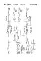
- FIG. 1is a functional block diagram of an external transmitter of the invention
- FIG. 2shows the auto power down circuit of the transmitter of FIG. 1;
- FIG. 3illustrates a preferred antenna of the external transmitter
- FIG. 4shows circuitry of the auto power down and low voltage power supply portions of the embodiment of FIG. 1;
- FIG. 5shows circuitry of the medium voltage power supply and amplifier of the embodiment of FIG. 1;
- FIG. 5 aillustrate overall connection of the aforesaid circuits through a gate array in the embodiment of FIG. 1;
- FIGS. 6 a and 6 billustrate logic of various timing and pulse forming units defined by the FPGA.
- FIG. 1shows a functional block diagram of the external transmitter assembly 10 of the present invention which powers an implant 100 .
- the transmitter 10employs a battery 1 which couples via an auto power down circuit 5 to the active elements of the transmitter.
- the auto power down circuit 5may be initially actuated to turn on the device by a manually operated switch thrown by the user, and it receives a further input from an FPGA 20 indicative of the end of a treatment cycle, at which time it disconnects power independently of the present state of the user switch.
- the batterypowers a low voltage power supply 25 and a variable medium voltage power supply 30 .
- the low voltage power supplypowers the FPGA 20
- the medium voltage supply 30drives a class D amplifier 40 .
- Amplifier 40receives an input signal from the FPGA 20 and amplifies it to produce a high powered signal which is applied to the external coil 50 for inductively coupling energy into the implant.
- Power supply 30is an output limited power supply, and couples via hold up capacitors and an RC filter network (FIG. 5) to the amplifier 40 allowing amplifier operation at high current pulse levels without impairing operation of the other elements which depend upon power from the small battery supply, which may, for example consist of two AA cells and have limited capacity.
- FIG. 2schematically illustrates the construction of the auto power down circuit 5 of the transmitter 10 .
- the battery 1is connected via a manually operated switch 2 to a reset generator 3 a and to the power terminal of a FET switch 3 b .
- the reset generator 3 agenerates a fixed reset pulse which through a logic gate 3 c forces the FET switch into an ON state.
- the main low voltage power supplyautomatically starts functioning and drives the FPGA which runs through its boot cycle and provides an enable signal through a logic gate to force the FET to remain ON.
- the unitwill again turn itself off.
- the FPGAOnce the FPGA has forced the FET ON it will remain on until the end of a treatment cycle at which time the FPGA turns OFF the FET through the logic gate, and the battery power to the unit is turned off.
- user actuation of the manual switch 2is required to turn the unit ON, while either an FPGA signal or a user switch movement can turn the unit OFF. This assures that the unit cannot accidently turn itself ON when the user is not expecting it.
- a battery life comparatoralso assures that the circuit operates even when the battery is starting to go dead. The overall circuit is designed to draw so little power that there will be negligible effect on battery life if the user leaves the unit in its shut down state for extended periods of time.
- FIG. 3illustrates in simplified form the preferred configuration of transmitting and receiving coils 50 , 100 .
- the implant 100has a multi-winding coil which may for example have a diameter of approximately one centimeter.
- the transmitter coil 50on the other hand, which is illustrated attached to or housed within a thin adhesive epidermal patch or box, has a diameter greater than that of the implanted coil 100 .
- the coil 50may have a diameter of 1.5 to 2.5 centimeters, fifty to one hundred fifty percent greater than the diameter of the implanted coil, so that its projected profile forms a band lying roughly several millimeters outside the perimeter of the implanted receiving coil.
- the transmitter coilis sufficiently small to provide a relatively high magnetic coupling field, while being sufficiently large that it is readily positioned on the surface of the skin with the receiving coil 100 lying within its contour but proximate to the external coil windings. Slight shifting of their relative positions therefore enhances inductive coupling along a portion of the coil circumference to an extent comparable to its decrease in the complementary portion, with the result that coupling efficiency remains both high and relatively constant, even when an eccentricity or misalignment of several millimeters occurs.
- the circuit elementsare configured to be ON and drawing power precisely during intervals of operation required for the functional application of treatment pulses to the vicinity of a nerve or nerve bundle.
- the user actuated switch 2(FIG. 2) connects the battery for the duration of the reset interval set by the reset generator, and during this time the FET switch 3 b connects the battery to the low voltage power supply 25 (FIGS. 1 and 4 ).
- the programmable gate arraythen proceeds to define suitable nerve treatment pulse sequences, which are amplified to drive the transmitter coil 50 and thus supply relatively short signals to the implanted nerve stimulation electrode.
- One typical drive regimentinvolves a stimulation pulse of duration 50-250 microseconds, applied ten or twenty times per second, either for a few seconds, several minutes, or continuously.
- the medium voltage power supply 30is ON during pulse amplification for treatment regimens, at which time it powers the amplifier 40 to create energy pulses which, for application in the vicinity of the sacral nerve for treating urinary incontinence as described in the aforesaid two United States patents, may, for example, apply pulses of 200 microseconds duration at intervals of about 50 milliseconds, either continuously, or for a defined number of times.
- Other programmed antenna excitation regimensmay be provided as appropriate for different nerve treatments and other medical conditions.
- FIGS. 4 and 5illustrate circuit elements of the auto power-down circuitry, the power supplies and the amplifier in greater detail.
- the auto power-down circuitryinclude a battery check section 6 wherein a divider bridge 6 a operative on the low voltage line produces threshold voltages for comparison to the battery supply to actuate indicator lights for displaying when the battery is low or ceases to be good.
- a “battery low” line 7 agoes high below a threshold that represents a remaining battery life of approximately ten per cent, while the “battery depleted” line 7 b goes low when the voltage drops below a point where the battery voltage is too low to correctly power the device.
- These outputsconnect to the FPGA/modulation control unit 20 (FIG.
- the battery low LEDmay be an amber LED while more extreme level of depletion may be indicated by blinking actuation, a separate color LED or the like. As described further below, preferably a separate LED is illuminated to indicate when a treatment cycle is in progress.
- FIG. 5illustrates the output driver block including the variable medium voltage power supply 30 and the amplifier section 40 of the external transmitter 10 .
- an intensity adjustment potentiometertogether with a constant current source adjusts the power output, while capacitors C 30 and C 31 between the input and ground, and capacitor C 29 between the output and ground, stabilize and filter the switching converter, U 9 .
- the ground connections of C 29 to C 31are placed as close as possible to the grounded pin 4 of circuit element U 9 , with the other ends of capacitors C 30 and C 31 positioned as close as possible to the voltage input pin 6 to enhance power limited smooth operation when the amplifier presents a high draw.
- the filtering resistor, R 26together with C 28 absorb large pulse currents.
- Amplifier 40operates with parallel drive channels A and B, which as shown connect to a bridge at the output.
- the channelsmay be run separately by removing the FETs of the bridge and using simply jumpers R 20 , R 22 , or the full bridge may be employed by removing the jumpers.
- Amplifier 40is a class D amplifier, i.e., it operates by rapidly switching the drive voltage in accordance with the signals provided at its input terminals and a high frequency switching signal supply.
- a two bit state controllerselects among the frequencies of 7.2000, 7.3728 and 9.8304 megahertz as appropriate to generate the pulse duration and repetition frequencies and for the transmitter transmitter frequency synthesis.
- FIG. 5Aillustrates the FPGA 20 and representative pin connections in the prototype embodiment.
- a local oscillator 21 aprovides a high frequency standard at 9.8304 MHZ
- additional oscillatorsmay be provided for the switching frequencies of the power supplies, or the transmission and switching frequencies may be synthesized from the basic high frequency.
- the three frequenciesare distinct, and the switching frequencies of the power supplies are all below the nominal transmission frequency, which may be, for example tuned to 5 MHz.
- the FPGAimplements various software modules for creating a 10 KHz pulse control clock, a 10 Hz clock for applications such as treatment timeout or LED blinking control, and various timeout counters with periods of several microseconds to one hour for pulse, treatment or treatment regimen interval definition.
- the FPGAprovides appropriate timing signals for battery sample and hold circuit to perform the voltage tests necessary for the battery indicator lights and overall battery management.
- the battery voltageis synchronously sampled just before the next current pulse; this helps assure that the sampled voltage is representative of the remaining battery life and is not artificially depressed by sampling during a transient current pulse. Overall logic for these operations is illustrated schematically in FIGS. 6A and 6B.
- the overall construction of the external transmitter of the present inventioninvolves a flexibly programmable control unit having low drive voltage requirements and operating flexibly to first provide an auto power down and power management system, and secondly, to define treatment pulses and synchronize operation a current-limited driver power supply and Class D amplifier with the defined pulse regimen so as to effectively deliver power to a tuned transmitter coil.
- Thisprovides a programmed sequence of treatment pulses for nerve stimulation over an extended period of time using simple disposable batteries.
Landscapes
- Engineering & Computer Science (AREA)
- Power Engineering (AREA)
- Health & Medical Sciences (AREA)
- Computer Networks & Wireless Communication (AREA)
- Life Sciences & Earth Sciences (AREA)
- Radiology & Medical Imaging (AREA)
- Nuclear Medicine, Radiotherapy & Molecular Imaging (AREA)
- Animal Behavior & Ethology (AREA)
- General Health & Medical Sciences (AREA)
- Public Health (AREA)
- Veterinary Medicine (AREA)
- Biomedical Technology (AREA)
- Electrotherapy Devices (AREA)
Abstract
Description
Claims (5)
Priority Applications (2)
| Application Number | Priority Date | Filing Date | Title |
|---|---|---|---|
| US09/472,071US6477425B1 (en) | 1999-12-23 | 1999-12-23 | External transmitter for implanted medical device |
| US10/213,213US20020188333A1 (en) | 1999-12-23 | 2002-08-06 | External battery power source for implanted medical devices |
Applications Claiming Priority (1)
| Application Number | Priority Date | Filing Date | Title |
|---|---|---|---|
| US09/472,071US6477425B1 (en) | 1999-12-23 | 1999-12-23 | External transmitter for implanted medical device |
Related Child Applications (1)
| Application Number | Title | Priority Date | Filing Date |
|---|---|---|---|
| US10/213,213ContinuationUS20020188333A1 (en) | 1999-12-23 | 2002-08-06 | External battery power source for implanted medical devices |
Publications (1)
| Publication Number | Publication Date |
|---|---|
| US6477425B1true US6477425B1 (en) | 2002-11-05 |
Family
ID=23874088
Family Applications (2)
| Application Number | Title | Priority Date | Filing Date |
|---|---|---|---|
| US09/472,071Expired - LifetimeUS6477425B1 (en) | 1999-12-23 | 1999-12-23 | External transmitter for implanted medical device |
| US10/213,213AbandonedUS20020188333A1 (en) | 1999-12-23 | 2002-08-06 | External battery power source for implanted medical devices |
Family Applications After (1)
| Application Number | Title | Priority Date | Filing Date |
|---|---|---|---|
| US10/213,213AbandonedUS20020188333A1 (en) | 1999-12-23 | 2002-08-06 | External battery power source for implanted medical devices |
Country Status (1)
| Country | Link |
|---|---|
| US (2) | US6477425B1 (en) |
Cited By (30)
| Publication number | Priority date | Publication date | Assignee | Title |
|---|---|---|---|---|
| WO2005031944A1 (en)* | 2003-09-29 | 2005-04-07 | Auckland Uniservices Limited | Inductively powered power transfer system with one or more independently controllable loads |
| US20060084934A1 (en)* | 2004-10-18 | 2006-04-20 | Milton Frank | Transponder assembly and method for making same |
| US20060149340A1 (en)* | 2002-07-31 | 2006-07-06 | Karunasiri Rankiri T | Systems and methods for providing power to one or more implantable devices |
| US20070049992A1 (en)* | 2005-08-29 | 2007-03-01 | Cardiac Pacemakers, Inc. | Pacemaker RF telemetry repeater and method |
| US20070255349A1 (en)* | 2006-04-28 | 2007-11-01 | Medtronic, Inc. | Antenna for an external power source for an implantable medical device, system and method |
| WO2007126454A2 (en) | 2006-04-28 | 2007-11-08 | Medtronic, Inc. | System for transcutaneous energy transfer to an implantable medical device with mating elements |
| US7794499B2 (en) | 2004-06-08 | 2010-09-14 | Theken Disc, L.L.C. | Prosthetic intervertebral spinal disc with integral microprocessor |
| WO2011072144A1 (en)* | 2009-12-09 | 2011-06-16 | Georgia Tech Research Corporation | Pulse harmonic modulation systems and methods |
| US20110190852A1 (en)* | 2010-02-03 | 2011-08-04 | Dinsmoor David A | Implantable medical devices and systems having dual frequency inductive telemetry and recharge |
| US20110190853A1 (en)* | 2010-02-03 | 2011-08-04 | Dinsmoor David A | Implantable medical devices and systems having power management for recharge sessions |
| US8594806B2 (en) | 2010-04-30 | 2013-11-26 | Cyberonics, Inc. | Recharging and communication lead for an implantable device |
| US9089712B2 (en) | 2011-04-29 | 2015-07-28 | Cyberonics, Inc. | Implantable medical device without antenna feedthrough |
| US9136728B2 (en) | 2011-04-28 | 2015-09-15 | Medtronic, Inc. | Implantable medical devices and systems having inductive telemetry and recharge on a single coil |
| US9240630B2 (en) | 2011-04-29 | 2016-01-19 | Cyberonics, Inc. | Antenna shield for an implantable medical device |
| US9259582B2 (en) | 2011-04-29 | 2016-02-16 | Cyberonics, Inc. | Slot antenna for an implantable device |
| US9265958B2 (en) | 2011-04-29 | 2016-02-23 | Cyberonics, Inc. | Implantable medical device antenna |
| US9526906B2 (en) | 2012-07-26 | 2016-12-27 | Nyxoah SA | External resonance matching between an implanted device and an external device |
| US9564777B2 (en) | 2014-05-18 | 2017-02-07 | NeuSpera Medical Inc. | Wireless energy transfer system for an implantable medical device using a midfield coupler |
| US9610457B2 (en) | 2013-09-16 | 2017-04-04 | The Board Of Trustees Of The Leland Stanford Junior University | Multi-element coupler for generation of electromagnetic energy |
| US9643022B2 (en) | 2013-06-17 | 2017-05-09 | Nyxoah SA | Flexible control housing for disposable patch |
| CN106655527A (en)* | 2015-10-28 | 2017-05-10 | 三星电机株式会社 | Wireless power transmission apparatus and method of controlling the same |
| US9849289B2 (en) | 2009-10-20 | 2017-12-26 | Nyxoah SA | Device and method for snoring detection and control |
| US9943686B2 (en) | 2009-10-20 | 2018-04-17 | Nyxoah SA | Method and device for treating sleep apnea based on tongue movement |
| US10052097B2 (en) | 2012-07-26 | 2018-08-21 | Nyxoah SA | Implant unit delivery tool |
| US10751537B2 (en) | 2009-10-20 | 2020-08-25 | Nyxoah SA | Arced implant unit for modulation of nerves |
| US10814137B2 (en) | 2012-07-26 | 2020-10-27 | Nyxoah SA | Transcutaneous power conveyance device |
| US11033737B2 (en) | 2014-08-17 | 2021-06-15 | Coloplast A/S | Miniature implantable neurostimulator system for sciatic nerves and their branches |
| US11253712B2 (en) | 2012-07-26 | 2022-02-22 | Nyxoah SA | Sleep disordered breathing treatment apparatus |
| US11338148B2 (en) | 2015-05-15 | 2022-05-24 | NeuSpera Medical Inc. | External power devices and systems |
| US12053630B2 (en) | 2014-08-17 | 2024-08-06 | Coloplast A/S | Implantable pulse generator with automatic jump-start |
Families Citing this family (8)
| Publication number | Priority date | Publication date | Assignee | Title |
|---|---|---|---|---|
| WO2003099102A2 (en)* | 2002-05-20 | 2003-12-04 | Kevin Marchitto | Device and method for wound healing and uses therefor |
| FR2883428B1 (en)* | 2005-03-18 | 2008-03-14 | Michel Burri | METHOD FOR RECHARGING A BATTERY OR BATTERY OF AN ELECTRONIC EQUIPMENT USING A CHARGER AND ELECTRONIC EQUIPMENT SUITABLE FOR SUCH A METHOD |
| WO2007019491A2 (en)* | 2005-08-08 | 2007-02-15 | Katims Jefferson J | Method and apparatus for producing therapeutic and diagnostic stimulation |
| US20100187910A1 (en)* | 2008-01-29 | 2010-07-29 | Alexander Brengauz | Method and system for wireless delivery of power and control to a miniature wireless apparatuses |
| US9415215B2 (en) | 2009-10-20 | 2016-08-16 | Nyxoah SA | Methods for treatment of sleep apnea |
| US8577472B2 (en) | 2009-10-20 | 2013-11-05 | Nyxoah SA | Systems and methods for determining a sleep disorder based on positioning of the tongue |
| US9504828B2 (en) | 2012-07-26 | 2016-11-29 | Nyxoah SA | Electrical contacts on a medical device patch |
| CN108614790B (en)* | 2018-05-03 | 2021-02-05 | 浪潮集团有限公司 | Vehicle-mounted computing unit, vehicle and automatic vehicle driving method |
Citations (10)
| Publication number | Priority date | Publication date | Assignee | Title |
|---|---|---|---|---|
| US4679560A (en)* | 1985-04-02 | 1987-07-14 | Board Of Trustees Of The Leland Stanford Junior University | Wide band inductive transdermal power and data link |
| US5094242A (en) | 1988-11-07 | 1992-03-10 | Regents Of The University Of California | Implantable nerve stimulation device |
| US5211175A (en) | 1988-11-07 | 1993-05-18 | Regents Of The University Of California | Method for implanting electra-acupuncture needle |
| US5306986A (en)* | 1992-05-20 | 1994-04-26 | Diablo Research Corporation | Zero-voltage complementary switching high efficiency class D amplifier |
| US5314457A (en)* | 1993-04-08 | 1994-05-24 | Jeutter Dean C | Regenerative electrical |
| US5405367A (en)* | 1991-12-18 | 1995-04-11 | Alfred E. Mann Foundation For Scientific Research | Structure and method of manufacture of an implantable microstimulator |
| US5755748A (en)* | 1996-07-24 | 1998-05-26 | Dew Engineering & Development Limited | Transcutaneous energy transfer device |
| US5891183A (en) | 1996-06-04 | 1999-04-06 | Med-El Elektromedizinische Gerate Ges.M.B.H. | Device for transferring electromagnetic energy between primary and secondary coils |
| US6058330A (en)* | 1998-03-06 | 2000-05-02 | Dew Engineering And Development Limited | Transcutaneous energy transfer device |
| US6240318B1 (en)* | 1998-10-27 | 2001-05-29 | Richard P. Phillips | Transcutaneous energy transmission system with full wave Class E rectifier |
- 1999
- 1999-12-23USUS09/472,071patent/US6477425B1/ennot_activeExpired - Lifetime
- 2002
- 2002-08-06USUS10/213,213patent/US20020188333A1/ennot_activeAbandoned
Patent Citations (10)
| Publication number | Priority date | Publication date | Assignee | Title |
|---|---|---|---|---|
| US4679560A (en)* | 1985-04-02 | 1987-07-14 | Board Of Trustees Of The Leland Stanford Junior University | Wide band inductive transdermal power and data link |
| US5094242A (en) | 1988-11-07 | 1992-03-10 | Regents Of The University Of California | Implantable nerve stimulation device |
| US5211175A (en) | 1988-11-07 | 1993-05-18 | Regents Of The University Of California | Method for implanting electra-acupuncture needle |
| US5405367A (en)* | 1991-12-18 | 1995-04-11 | Alfred E. Mann Foundation For Scientific Research | Structure and method of manufacture of an implantable microstimulator |
| US5306986A (en)* | 1992-05-20 | 1994-04-26 | Diablo Research Corporation | Zero-voltage complementary switching high efficiency class D amplifier |
| US5314457A (en)* | 1993-04-08 | 1994-05-24 | Jeutter Dean C | Regenerative electrical |
| US5891183A (en) | 1996-06-04 | 1999-04-06 | Med-El Elektromedizinische Gerate Ges.M.B.H. | Device for transferring electromagnetic energy between primary and secondary coils |
| US5755748A (en)* | 1996-07-24 | 1998-05-26 | Dew Engineering & Development Limited | Transcutaneous energy transfer device |
| US6058330A (en)* | 1998-03-06 | 2000-05-02 | Dew Engineering And Development Limited | Transcutaneous energy transfer device |
| US6240318B1 (en)* | 1998-10-27 | 2001-05-29 | Richard P. Phillips | Transcutaneous energy transmission system with full wave Class E rectifier |
Cited By (60)
| Publication number | Priority date | Publication date | Assignee | Title |
|---|---|---|---|---|
| US20060149340A1 (en)* | 2002-07-31 | 2006-07-06 | Karunasiri Rankiri T | Systems and methods for providing power to one or more implantable devices |
| US7254449B2 (en)* | 2002-07-31 | 2007-08-07 | Advanced Bionics Corp | Systems and methods for providing power to one or more implantable devices |
| US7633235B2 (en) | 2003-09-29 | 2009-12-15 | Auckland Uniservices Limited | Inductively-powered power transfer system with one or more independently controllable loads |
| WO2005031944A1 (en)* | 2003-09-29 | 2005-04-07 | Auckland Uniservices Limited | Inductively powered power transfer system with one or more independently controllable loads |
| US7794499B2 (en) | 2004-06-08 | 2010-09-14 | Theken Disc, L.L.C. | Prosthetic intervertebral spinal disc with integral microprocessor |
| US20060084934A1 (en)* | 2004-10-18 | 2006-04-20 | Milton Frank | Transponder assembly and method for making same |
| US20070049992A1 (en)* | 2005-08-29 | 2007-03-01 | Cardiac Pacemakers, Inc. | Pacemaker RF telemetry repeater and method |
| US8417341B2 (en) | 2005-08-29 | 2013-04-09 | Cardiac Pacemakers, Inc. | Pacemaker RF telemetry repeater and method |
| US8027727B2 (en)* | 2005-08-29 | 2011-09-27 | Cardiac Pacemakers, Inc. | Pacemaker RF telemetry repeater and method |
| WO2007126454A3 (en)* | 2006-04-28 | 2008-03-13 | Medtronic Inc | System for transcutaneous energy transfer to an implantable medical device with mating elements |
| WO2007126454A2 (en) | 2006-04-28 | 2007-11-08 | Medtronic, Inc. | System for transcutaneous energy transfer to an implantable medical device with mating elements |
| US7848814B2 (en) | 2006-04-28 | 2010-12-07 | Medtronic, Inc. | System for transcutaneous energy transfer to an implantable medical device with mating elements |
| US7962211B2 (en) | 2006-04-28 | 2011-06-14 | Medtronic, Inc. | Antenna for an external power source for an implantable medical device, system and method |
| US20070255349A1 (en)* | 2006-04-28 | 2007-11-01 | Medtronic, Inc. | Antenna for an external power source for an implantable medical device, system and method |
| US20070255350A1 (en)* | 2006-04-28 | 2007-11-01 | Medtronic, Inc. | System for transcutaneous energy transfer to an implantable medical device with mating elements |
| US11273307B2 (en) | 2009-10-20 | 2022-03-15 | Nyxoah SA | Method and device for treating sleep apnea |
| US11857791B2 (en) | 2009-10-20 | 2024-01-02 | Nyxoah SA | Arced implant unit for modulation of nerves |
| US9943686B2 (en) | 2009-10-20 | 2018-04-17 | Nyxoah SA | Method and device for treating sleep apnea based on tongue movement |
| US9950166B2 (en) | 2009-10-20 | 2018-04-24 | Nyxoah SA | Acred implant unit for modulation of nerves |
| US10716940B2 (en) | 2009-10-20 | 2020-07-21 | Nyxoah SA | Implant unit for modulation of small diameter nerves |
| US10751537B2 (en) | 2009-10-20 | 2020-08-25 | Nyxoah SA | Arced implant unit for modulation of nerves |
| US10898717B2 (en) | 2009-10-20 | 2021-01-26 | Nyxoah SA | Device and method for snoring detection and control |
| US9849289B2 (en) | 2009-10-20 | 2017-12-26 | Nyxoah SA | Device and method for snoring detection and control |
| US8774291B2 (en) | 2009-12-09 | 2014-07-08 | Georgia Tech Research Corporation | Pulse harmonic modulation systems and methods |
| WO2011072144A1 (en)* | 2009-12-09 | 2011-06-16 | Georgia Tech Research Corporation | Pulse harmonic modulation systems and methods |
| US8909351B2 (en) | 2010-02-03 | 2014-12-09 | Medtronic, Inc. | Implantable medical devices and systems having dual frequency inductive telemetry and recharge |
| US9042995B2 (en) | 2010-02-03 | 2015-05-26 | Medtronic, Inc. | Implantable medical devices and systems having power management for recharge sessions |
| US20110190853A1 (en)* | 2010-02-03 | 2011-08-04 | Dinsmoor David A | Implantable medical devices and systems having power management for recharge sessions |
| US20110190852A1 (en)* | 2010-02-03 | 2011-08-04 | Dinsmoor David A | Implantable medical devices and systems having dual frequency inductive telemetry and recharge |
| US8594806B2 (en) | 2010-04-30 | 2013-11-26 | Cyberonics, Inc. | Recharging and communication lead for an implantable device |
| US9136728B2 (en) | 2011-04-28 | 2015-09-15 | Medtronic, Inc. | Implantable medical devices and systems having inductive telemetry and recharge on a single coil |
| US9265958B2 (en) | 2011-04-29 | 2016-02-23 | Cyberonics, Inc. | Implantable medical device antenna |
| US9259582B2 (en) | 2011-04-29 | 2016-02-16 | Cyberonics, Inc. | Slot antenna for an implantable device |
| US9240630B2 (en) | 2011-04-29 | 2016-01-19 | Cyberonics, Inc. | Antenna shield for an implantable medical device |
| US9089712B2 (en) | 2011-04-29 | 2015-07-28 | Cyberonics, Inc. | Implantable medical device without antenna feedthrough |
| US10716560B2 (en) | 2012-07-26 | 2020-07-21 | Nyxoah SA | Implant unit delivery tool |
| US10814137B2 (en) | 2012-07-26 | 2020-10-27 | Nyxoah SA | Transcutaneous power conveyance device |
| US9855032B2 (en) | 2012-07-26 | 2018-01-02 | Nyxoah SA | Transcutaneous power conveyance device |
| US9526906B2 (en) | 2012-07-26 | 2016-12-27 | Nyxoah SA | External resonance matching between an implanted device and an external device |
| US11730469B2 (en) | 2012-07-26 | 2023-08-22 | Nyxoah SA | Implant unit delivery tool |
| US11253712B2 (en) | 2012-07-26 | 2022-02-22 | Nyxoah SA | Sleep disordered breathing treatment apparatus |
| US10052097B2 (en) | 2012-07-26 | 2018-08-21 | Nyxoah SA | Implant unit delivery tool |
| US10918376B2 (en) | 2012-07-26 | 2021-02-16 | Nyxoah SA | Therapy protocol activation triggered based on initial coupling |
| US10512782B2 (en) | 2013-06-17 | 2019-12-24 | Nyxoah SA | Remote monitoring and updating of a medical device control unit |
| US9643022B2 (en) | 2013-06-17 | 2017-05-09 | Nyxoah SA | Flexible control housing for disposable patch |
| US11642534B2 (en) | 2013-06-17 | 2023-05-09 | Nyxoah SA | Programmable external control unit |
| US11298549B2 (en) | 2013-06-17 | 2022-04-12 | Nyxoah SA | Control housing for disposable patch |
| US9744369B2 (en) | 2013-09-16 | 2017-08-29 | The Board Of Trustees Of The Leland Stanford Junior University | Multi-element coupler for generation of electromagnetic energy |
| US10039924B2 (en) | 2013-09-16 | 2018-08-07 | The Board Of Trustees Of The Leland Stanford Junior University | Wireless midfield systems and methods |
| US9610457B2 (en) | 2013-09-16 | 2017-04-04 | The Board Of Trustees Of The Leland Stanford Junior University | Multi-element coupler for generation of electromagnetic energy |
| US9662507B2 (en) | 2013-09-16 | 2017-05-30 | The Board Of Trustees Of The Leland Stanford Junior University | Multi-element coupler for generation of electromagnetic energy |
| US9687664B2 (en) | 2013-09-16 | 2017-06-27 | The Board Of Trustees Of The Leland Stanford Junior University | Multi-element coupler for generation of electromagnetic energy |
| US9583980B2 (en) | 2014-05-18 | 2017-02-28 | NeuSpera Medical Inc. | Midfield coupler |
| US9564777B2 (en) | 2014-05-18 | 2017-02-07 | NeuSpera Medical Inc. | Wireless energy transfer system for an implantable medical device using a midfield coupler |
| US12176725B2 (en) | 2014-05-18 | 2024-12-24 | NeuSpera Medical Inc. | External power devices and systems |
| US11033737B2 (en) | 2014-08-17 | 2021-06-15 | Coloplast A/S | Miniature implantable neurostimulator system for sciatic nerves and their branches |
| US11679257B2 (en) | 2014-08-17 | 2023-06-20 | Coloplast A/S | Method of treating an overactive bladder condition |
| US12053630B2 (en) | 2014-08-17 | 2024-08-06 | Coloplast A/S | Implantable pulse generator with automatic jump-start |
| US11338148B2 (en) | 2015-05-15 | 2022-05-24 | NeuSpera Medical Inc. | External power devices and systems |
| CN106655527A (en)* | 2015-10-28 | 2017-05-10 | 三星电机株式会社 | Wireless power transmission apparatus and method of controlling the same |
Also Published As
| Publication number | Publication date |
|---|---|
| US20020188333A1 (en) | 2002-12-12 |
Similar Documents
| Publication | Publication Date | Title |
|---|---|---|
| US6477425B1 (en) | External transmitter for implanted medical device | |
| US11896837B2 (en) | Energy transfer control adapted to a medical device system | |
| US10576287B2 (en) | Efficiently delivering acoustic stimulation energy to tissue | |
| KR930001308B1 (en) | Wireless low frequency treatment device | |
| US7151914B2 (en) | Transmitter system for wireless communication with implanted devices | |
| US6864755B2 (en) | Switched reactance modulated E-class oscillator design | |
| US6591139B2 (en) | Low-power, high-modulation-index amplifier for use in battery-powered device | |
| US11612747B2 (en) | Optimization of application of current | |
| JP4088417B2 (en) | Ultrasound therapy controller | |
| US5735887A (en) | Closed-loop, RF-coupled implanted medical device | |
| US20090105782A1 (en) | Vagus nerve stimulation apparatus, and associated methods | |
| WO2007073557A2 (en) | Deep brain stimulation apparatus, and associated methods | |
| CA1086830A (en) | Implantable receiver circuit | |
| US20200406033A1 (en) | Non-Invasive Nerve Activator Patch With Adaptive Circuit | |
| EP1056510A1 (en) | Rf coupled, implantable medical device with rechargeable back-up power source | |
| US20060136007A1 (en) | Deep brain stimulation apparatus, and associated methods | |
| US20250205503A1 (en) | Wireless neuromodulation systems | |
| US12151094B2 (en) | Non-invasive nerve stimulator with battery management | |
| JPS62102768A (en) | Skin activating device |
Legal Events
| Date | Code | Title | Description |
|---|---|---|---|
| AS | Assignment | Owner name:UROSURGE CORPORATION, IOWA Free format text:ASSIGNMENT OF ASSIGNORS INTEREST;ASSIGNORS:NOWICK, MATTHEW;MALANEY, JAMES;REEL/FRAME:010716/0548;SIGNING DATES FROM 20000302 TO 20000318 | |
| AS | Assignment | Owner name:MMC/GATX PARTNERSHIP NO. 1, CALIFORNIA Free format text:ASSIGNMENT OF ASSIGNORS INTEREST;ASSIGNOR:UROSURGE, INC.;REEL/FRAME:012648/0466 Effective date:20011002 | |
| STCF | Information on status: patent grant | Free format text:PATENTED CASE | |
| AS | Assignment | Owner name:CYSTOMEDIX, INC., MINNESOTA Free format text:DOCUMENT RE-RECORDED TO CORRECT ERROR CONTAINED IN PROPERTY NUMBER 6447425 ON BILL OF SALE PREVIOUSLY RECORDED AT REEL 015251 FRAME 0171.;ASSIGNOR:MMC/GATX PARTNERSHIP NO. 1;REEL/FRAME:015394/0680 Effective date:20021018 | |
| FPAY | Fee payment | Year of fee payment:4 | |
| AS | Assignment | Owner name:UROPLASTY, INC., MINNESOTA Free format text:ASSIGNMENT OF ASSIGNORS INTEREST;ASSIGNOR:CYSTOMEDIX, INC.;REEL/FRAME:019628/0549 Effective date:20070406 | |
| FEPP | Fee payment procedure | Free format text:PAYER NUMBER DE-ASSIGNED (ORIGINAL EVENT CODE: RMPN); ENTITY STATUS OF PATENT OWNER: SMALL ENTITY Free format text:PAYOR NUMBER ASSIGNED (ORIGINAL EVENT CODE: ASPN); ENTITY STATUS OF PATENT OWNER: SMALL ENTITY | |
| FPAY | Fee payment | Year of fee payment:8 | |
| FPAY | Fee payment | Year of fee payment:12 | |
| AS | Assignment | Owner name:UROPLASTY, LLC, MINNESOTA Free format text:MERGER AND CHANGE OF NAME;ASSIGNORS:UROPLASTY, INC.;VISOR MERGER SUB LLC;REEL/FRAME:035445/0597 Effective date:20150331 | |
| AS | Assignment | Owner name:JPMORGAN CHASE BANK, N.A., ILLINOIS Free format text:SECURITY INTEREST;ASSIGNORS:COGENTIX MEDICAL, INC.;UROPLASTY LLC;LABORIE MEDICAL TECHNOLOGIES CANADA ULC;REEL/FRAME:045609/0561 Effective date:20180423 | |
| AS | Assignment | Owner name:UROPLASTY LLC, MINNESOTA Free format text:RELEASE OF SECURITY INTEREST IN PATENTS;ASSIGNOR:JPMORGAN CHASE BANK, N.A. AS ADMINISTRATIVE AGENT;REEL/FRAME:051906/0518 Effective date:20200212 Owner name:LABORIE MEDICAL TECHNOLOGIES CANADA ULC, CANADA Free format text:RELEASE OF SECURITY INTEREST IN PATENTS;ASSIGNOR:JPMORGAN CHASE BANK, N.A. AS ADMINISTRATIVE AGENT;REEL/FRAME:051906/0518 Effective date:20200212 Owner name:COGENTIX MEDICAL, INC., MINNESOTA Free format text:RELEASE OF SECURITY INTEREST IN PATENTS;ASSIGNOR:JPMORGAN CHASE BANK, N.A. AS ADMINISTRATIVE AGENT;REEL/FRAME:051906/0518 Effective date:20200212 |