US6477274B1 - Handwritten character recognition devices and electronic devices incorporating same - Google Patents
Handwritten character recognition devices and electronic devices incorporating sameDownload PDFInfo
- Publication number
- US6477274B1 US6477274B1US09/425,637US42563799AUS6477274B1US 6477274 B1US6477274 B1US 6477274B1US 42563799 AUS42563799 AUS 42563799AUS 6477274 B1US6477274 B1US 6477274B1
- Authority
- US
- United States
- Prior art keywords
- substrate
- array
- user
- sequence
- disposed
- Prior art date
- Legal status (The legal status is an assumption and is not a legal conclusion. Google has not performed a legal analysis and makes no representation as to the accuracy of the status listed.)
- Expired - Lifetime
Links
Images


Classifications
- H—ELECTRICITY
- H01—ELECTRIC ELEMENTS
- H01H—ELECTRIC SWITCHES; RELAYS; SELECTORS; EMERGENCY PROTECTIVE DEVICES
- H01H13/00—Switches having rectilinearly-movable operating part or parts adapted for pushing or pulling in one direction only, e.g. push-button switch
- H01H13/70—Switches having rectilinearly-movable operating part or parts adapted for pushing or pulling in one direction only, e.g. push-button switch having a plurality of operating members associated with different sets of contacts, e.g. keyboard
- H01H13/702—Switches having rectilinearly-movable operating part or parts adapted for pushing or pulling in one direction only, e.g. push-button switch having a plurality of operating members associated with different sets of contacts, e.g. keyboard with contacts carried by or formed from layers in a multilayer structure, e.g. membrane switches
- G—PHYSICS
- G06—COMPUTING OR CALCULATING; COUNTING
- G06V—IMAGE OR VIDEO RECOGNITION OR UNDERSTANDING
- G06V10/00—Arrangements for image or video recognition or understanding
- G06V10/10—Image acquisition
- G06V10/17—Image acquisition using hand-held instruments
- H—ELECTRICITY
- H04—ELECTRIC COMMUNICATION TECHNIQUE
- H04M—TELEPHONIC COMMUNICATION
- H04M1/00—Substation equipment, e.g. for use by subscribers
- H04M1/02—Constructional features of telephone sets
- H04M1/23—Construction or mounting of dials or of equivalent devices; Means for facilitating the use thereof
- H—ELECTRICITY
- H01—ELECTRIC ELEMENTS
- H01H—ELECTRIC SWITCHES; RELAYS; SELECTORS; EMERGENCY PROTECTIVE DEVICES
- H01H2239/00—Miscellaneous
- H01H2239/01—Miscellaneous combined with other elements on the same substrate
- H01H2239/012—Decoding impedances
- H—ELECTRICITY
- H04—ELECTRIC COMMUNICATION TECHNIQUE
- H04M—TELEPHONIC COMMUNICATION
- H04M1/00—Substation equipment, e.g. for use by subscribers
- H04M1/72—Mobile telephones; Cordless telephones, i.e. devices for establishing wireless links to base stations without route selection
- H04M1/724—User interfaces specially adapted for cordless or mobile telephones
Definitions
- the present inventionrelates generally to telecommunications devices and, more particularly, to devices for composing messages to be transmitted by telecommunications devices.
- Radiotelephonesgenerally refer to communications terminals which provide a wireless communications link to one or more other communications terminals. Radiotelephones may be used in a variety of different applications, including cellular telephone, land-mobile (e.g., police and fire departments), and satellite communications systems. With their increase in popularity, radiotelephones have been undergoing miniaturization to facilitate storage and portability. Indeed, some contemporary radiotelephone models are only 9-12 centimeters in length.
- SMSShort Message Service
- GSMGlobal System for Mobile
- SMS messagesare conventionally composed using the keypad of a telecommunications device, such as a radiotelephone.
- a radiotelephone keypadtypically performs multiple functions.
- numeric key “2”may also represent the characters “A”, “B” and “C” when activated.
- a usermay have to press the keys of the keypad in long, awkward sequences. For example, to select the character “C”, a user may have to press the “2” key multiple times to cycle through the possible functions of the key. Composing a simple message of just a few words may require many keystrokes. As such, composing SMS messages in this manner may be difficult and confusing to users.
- radiotelephonesAs radiotelephones become smaller, less area may be available for keypads. Accordingly, keypads may also become smaller, with the size and spacing of keys decreasing. As keypads become smaller through radiotelephone miniaturization, users may find it more difficult to compose SMS messages. To accommodate radiotelephone miniaturization, it may become necessary to eliminate certain radiotelephone functions because of lack of space for keys to adequately perform these functions. Alternatively, it may be necessary to require certain keys to perform many additional functions.
- Voice recognition devicesmay also be utilized to compose SMS messages via telecommunications devices.
- voice recognition techniquesmay require enhanced memory and processor capabilities that may increase costs associated with manufacturing.
- voice recognition techniquesmay have limited vocabularies from which messages can be composed.
- the use of voice recognition in publicmay be undesirable because of privacy concerns.
- Handwriting recognition devicesmay also be utilized to compose SMS messages via telecommunications devices and may overcome the limited vocabulary problem associated with voice recognition devices.
- conventional handwriting recognition devicesmay require high-resolution touch pads and various complex and expensive electronic components which can increase the manufacturing costs of telecommunications devices.
- a plurality of adjacent touch switchesare arranged in an array beneath an exposed touch pad. Each touch switch in the array produces a respective analog voltage signal (“on” or “off”) in response to user activation of an area of the touch pad during a handwriting stroke.
- An analog/digital converterreceives and converts a sequence of analog voltage signals produced by a user activating one or more of the touch switches during a handwriting stroke into a sequence of digital values.
- a processorworking in conjunction with a handwriting recognition algorithm, processes the sequence of digital values, recognizes the alphanumeric characters that corresponds to the handwriting strokes of the user, and then displays the recognized alphanumeric characters within the radiotelephone display.
- Input devicesthat recognize and display handwritten alphanumeric characters within a radiotelephone display according to the present invention may be located in various positions and locations on a radiotelephone housing.
- an array of touch switchesmay be located on a flip cover of a radiotelephone so as to be exposed when the flip cover is in an open position. Applying pressure to the touch pad surface using a stylus or other object, including a finger, a user may form individual alphanumeric characters via conventional handwriting strokes.
- Input devicesmay require less space than conventional radiotelephone keypads. Accordingly, radiotelephone miniaturization efforts can be accommodated by the present invention. Furthermore, handwriting recognition devices according to the present invention may not require enhanced memory or processor capabilities as compared with conventional high resolution touchpads which typically detect handwriting at the pixel level and, thus, may require high resolution analog/digital converters.
- FIG. 1is a schematic illustration of a conventional arrangement of electronic components for enabling a radiotelephone to transmit and receive radiotelephone communications signals.
- FIG. 2is a perspective view of an exemplary radiotelephone having a flip cover and in which an input device that recognizes and displays handwritten alphanumeric characters according to the present invention may be incorporated.
- FIG. 3is a schematic illustration of an input device that recognizes and displays handwritten alphanumeric characters within an electronic device display according to the present invention.
- FIG. 4is a perspective view of a radiotelephone having an array of touch switches for an input device according to the present invention disposed within a flip cover thereof.
- FIG. 5illustrates a conventional handwriting stroke of a user for the alphanumeric character “L” via the array of touch switches of FIG. 4 .
- FIG. 6is an enlarged partial plan view of the flip cover and touch switch array of FIG. 4 .
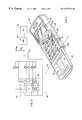
- FIG. 7is a cross-sectional view of adjacent touch switches 4 and 2 of FIG. 6 taken along lines 7 — 7 and illustrating a first embodiment thereof.
- FIG. 8is a cross-sectional view of adjacent touch switches 4 and 2 of FIG. 6 taken along lines 7 — 7 and illustrating a second embodiment thereof.
- FIG. 1A conventional arrangement of electronic components that enable a radiotelephone to transmit and receive telecommunications signals is shown schematically in FIG. 1, and is understood by those skilled in the art of radiotelephone communications.
- An antenna 10 for receiving and transmitting wireless telecommunications signalsis electrically connected to a radio-frequency transceiver 11 that is further electrically connected to a controller 12 , such as a microprocessor.
- the controller 12is electrically connected to a speaker 13 that transmits a remote signal from the controller 12 to a user of a radiotelephone.
- the controller 12is also electrically connected to a microphone 14 that receives a voice signal from a user and transmits the voice signal through the controller 12 and transceiver 11 to a remote device.
- the controller 12is electrically connected to a keypad 15 and display 16 that facilitate radiotelephone operation.
- the illustrated radiotelephone 20includes a top handset housing 24 and a bottom handset housing 26 connected thereto to form a cavity therein.
- Top and bottom handset housings 24 and 26house a keypad 28 including a plurality of keys 29 , a display 30 , and electronic components (not shown) that enable the radiotelephone 20 to transmit and receive radiotelephone communications signals.
- the display 30is configured to display sequences of alphanumeric characters that represent telephone numbers to be dialed, other commands to be executed by the radiotelephone 20 , or SMS messages to be transmitted by the radiotelephone 20 .
- a flip cover 22is hinged to a lower end 24 a of the top housing 24 , as illustrated.
- the flip cover 22may be pivoted by a user about an axis A between an open position and a closed position.
- the flip cover 22may provide protection to the keypad 28 mounted within the top handset housing 24 from unintentional activation or exposure to the elements.
- the flip cover 22may provide a convenient extension to the radiotelephone 20 and, when fitted with a microphone, may be favorably positioned to receive audio input from a user.
- alphanumeric charactersmay be entered into the display 30 via the various keys 29 of the keypad 28 .
- the input device 40includes a plurality of adjacent touch switches arranged in an array 42 .
- the touch switchesare individually numbered 1 - 6 , as illustrated.
- Each touch switch in the array 42produces a respective analog voltage signal in response to user activation during a handwriting stroke on a touchpad 43 overlying the array 42 .
- An analog/digital converter 44receives and converts the sequence of analog voltage signals produced by a user activating one or more of the touch switches during a handwriting stroke into a sequence of digital values.
- a processor 46that may be embodied as a general purpose processor running a stored program, a special purpose processor and/or a special purpose logic circuit, processes the sequence of digital values, recognizes the alphanumeric characters that corresponds to the handwriting strokes of the user, and then displays the recognized alphanumeric characters within the display of an electronic device, such as a radiotelephone.
- a touch pad 43 including an array 42 of switches disposed thereunderis disposed within the flip cover 22 of the illustrated radiotelephone 20 .
- the touch pad 43is exposed when the flip cover 22 is in the open position and is configured to receive handwriting strokes from a user.
- the individual switches in the array 42which are positioned beneath the touch pad 43 , are indicated in phantom lines in FIG. 4 .
- the touch pad 43includes a top surface 43 a upon which a user “writes”. Applying pressure to the touch pad top surface 43 a using a stylus or other object, including a finger, a user may form individual alphanumeric characters via conventional handwriting strokes.
- FIG. 5illustrates a conventional handwriting stroke a user may use for entering an “L” in the display of a radiotelephone via the input device of the present invention.
- the handwriting stroke for producing the illustrated “L” charactercreates the following activation sequence of switches in the array 42 : 1 - 3 - 5 - 6 .
- An analog/digital converter ( 44 , FIG. 3)converts this sequence into a sequence of digital values which are then processed by a processor ( 46 , FIG. 3 ). It will be understood that the analog/digital converter( 44 , FIG. 3) maybe incorporated into the processor ( 46 , FIG. 3 ), so that the analog voltages may be applied directly to the processor.
- the resistors (R 1 -R 6 ), analog/digital converter( 44 , FIG. 3 )and processor ( 46 , FIG. 3)may be embodied in a single integrated circuit.
- each touch switch within the array 42is preferably an “area” touch switch that generates a respective analog voltage signal when a user touches any portion thereof.
- Each touch switchis connected with a respective resistor (R 1 -R 6 ) electrically connected in series with an analog/digital converter 44 via a two-wire circuit, as illustrated.
- Each resistor (R 1 -R 6 )has a respective resistance value that is different from the other resistors (R 1 -R 6 ).
- the value of R 1may be greater than the value of R 2 ; the value of R 2 may be greater than the value of R 3 ; and so forth (i.e., R 1 >R 2 >R 3 >R 4 >R 5 >R 6 ).
- V inV ref ⁇ (R 1 /(R 0 +R 1 )).
- V inrepresents the analog voltage signal from closure of a switch;
- V refrepresents a reference voltage applied to the input device 40 ;
- R 0represents the resistance of the resistor that provides a voltage divider.
- each touch switch in the array 42generates a different, respective voltage signal.
- signal voltageBy measuring signal voltage, it can be determined which touch switch has been depressed (i.e., closed) by a user during a handwriting stroke.
- the difference in resistance between the resistors(R 1 -R 6 )is large so that a coarse and relatively inexpensive analog/digital converter may be utilized.
- a 3 bit analog/digital convertermay be used. This can be a significant advantage of the present invention over conventional high resolution touchpads which typically detect handwriting at the pixel level and, thus, require high resolution analog/digital converters (i.e., typically greater than 10 bit resolution).
- FIG. 6is an enlarged partial plan view of the flip cover and touch pad 43 of FIG. 6 taken along lines 7 — 7 .
- FIG. 7is a side cross-sectional view of adjacent touch switches 4 and 2 in the array 42 of FIG. 4 .
- the touch pad 43is an elastic substrate preferably formed from a dielectric material.
- the illustrated touch pad 43has opposite upper and lower surfaces 43 a , 43 b .
- An exemplary dielectric material out of which the touch pad 43 may be formedincludes, but is not limited to MYLAR® brand flexible film (E. I. du Pont de Nemours and Company, 1007 Market St., Wilmington Del. 19898).
- a plurality of spaced apart conductive pads 48are disposed on the lower surface 43 b of the touch pad 43 in the pattern of the array 42 .
- Each conductive pad 48is connected with a respective series resistor.
- each conductive pad 48is formed from a polymeric material, or a natural or synthetic rubber.
- each conductive pad 48has conductive material disposed thereon, such as gold plating, or impregnated therein, such as with carbon.
- a plurality of thin dielectric spacers 49are provided and define the outer perimeter of each switch in the array 42 , as illustrated.
- the spacers 49restrict contact between a conductive pad 48 and the switch plate 52 to the area of the touch pad 43 that has been depressed by a user during a handwriting stroke.
- a lower substrate 50such as a printed circuit board (PCB), having a gold-plated switch plate 52 disposed on a surface 50 a thereof is maintained in spaced apart relationship with the touch pad 43 such that each conductive pad 48 and the ground plate 50 are in spaced-apart, face-to-face relationship.
- PCBprinted circuit board
- the touch pad 43elastically deforms when the upper surface 43 a thereof is depressed by a user during a handwriting stroke.
- the touch pad 43displaces a respective conductive pad 48 into contact with the ground plate 52 to produce a respective analog voltage signal.
- the conductive pad 48 for switch 4makes contact with the ground plate 52 and a respective analog voltage signal is generated.
- the conductive pad 48 for switch 2makes contact with the ground plate 52 and a respective analog voltage signal is generated.
- FIG. 8is a side, cross-sectional view of adjacent touch switches 4 and 2 in the array 42 of FIG. 6, also taken along lines 7 — 7 , illustrating an alternative embodiment thereof.
- a continuous conductive substrate 48 ′is utilized in lieu of the plurality of conductive pads 48 illustrated in the embodiment of FIG. 7.
- a plurality of thin dielectric spacers 49are provided and define the outer perimeter of each switch in the array 42 , as illustrated. The spacers 49 restrict contact between the continuous conductive substrate 48 ′ and the ground plate 52 to the area of the touch pad 43 that has been depressed by a user during a handwriting stroke.
- the touch pad 43elastically deforms when the upper surface 43 a thereof is depressed by a user during a handwriting stroke.
- the touch pad 43displaces a portion of the continuous conductive substrate 48 ′ into contact with the switch plate 52 to produce a respective analog voltage signal.
- the continuous conductive substrate 48 ′ associated with switch 4makes contact with the switch plate 52 and a respective analog voltage signal is generated.
- each switch plate 52is electrically isolated from other switch plates 52 and each switch plate 52 is connected with a respective series resistor.
- the continuous conductive substrate 48 ′ associated with switch 2makes contact with the ground plate 52 and a respective analog voltage signal is generated.
- the input device processor 46may be configured to work in conjunction with a handwriting recognition algorithm.
- Handwriting recognition algorithmsare known to those of skill in the art and need not be described further herein.
- the present inventionmay be utilized with various electronic devices and is not limited to use with telecommunications devices.
- the present inventionmay also be used with wireless communications devices which only transmit or receive radio frequency signals.
- the touch pad 43 and array 42 of touch switches described abovemay have various configurations and may be located in various positions and locations on a radiotelephone housing and flip cover and are not limited to the illustrated configurations, positions and locations.
Landscapes
- Engineering & Computer Science (AREA)
- Physics & Mathematics (AREA)
- General Physics & Mathematics (AREA)
- Multimedia (AREA)
- Theoretical Computer Science (AREA)
- Signal Processing (AREA)
- Character Discrimination (AREA)
- Telephone Set Structure (AREA)
- Input From Keyboards Or The Like (AREA)
Abstract
Description
Claims (37)
Priority Applications (10)
| Application Number | Priority Date | Filing Date | Title |
|---|---|---|---|
| US09/425,637US6477274B1 (en) | 1999-10-22 | 1999-10-22 | Handwritten character recognition devices and electronic devices incorporating same |
| JP2001534075AJP2003513539A (en) | 1999-10-22 | 2000-08-29 | Handwritten character recognition device and electronic device incorporating the same |
| DE60012770TDE60012770D1 (en) | 1999-10-22 | 2000-08-29 | DEVICE FOR RECOGNIZING HANDWRITTEN CHARACTERS AND ELECTRONIC DEVICES CONTAINING THIS DEVICE |
| PCT/US2000/040766WO2001031567A1 (en) | 1999-10-22 | 2000-08-29 | Handwritten character recognition devices and electronic devices incorporating same |
| AU80359/00AAU8035900A (en) | 1999-10-22 | 2000-08-29 | Handwritten character recognition devices and electronic devices incorporating same |
| EP00971068AEP1224611B1 (en) | 1999-10-22 | 2000-08-29 | Handwritten character recognition devices and electronic devices incorporating same |
| AT00971068TATE272870T1 (en) | 1999-10-22 | 2000-08-29 | DEVICE FOR RECOGNIZING HANDWRITTEN CHARACTERS AND ELECTRONIC DEVICES CONTAINING SAME DEVICE |
| CN00817500ACN1413334A (en) | 1999-10-22 | 2000-08-29 | Handwriting character recognition devices and electronic devices incorporating same |
| MYPI20004137AMY122282A (en) | 1999-10-22 | 2000-09-07 | Handwritten character recognition devices and electronic devices incorporating same |
| CO00070437ACO5290339A1 (en) | 1999-10-22 | 2000-09-18 | DEVICE FOR RECOGNITION OF HANDWRITTEN CHARACTERS AND ELECTRONIC DEVICES THAT INCLUDE THEM |
Applications Claiming Priority (1)
| Application Number | Priority Date | Filing Date | Title |
|---|---|---|---|
| US09/425,637US6477274B1 (en) | 1999-10-22 | 1999-10-22 | Handwritten character recognition devices and electronic devices incorporating same |
Publications (1)
| Publication Number | Publication Date |
|---|---|
| US6477274B1true US6477274B1 (en) | 2002-11-05 |
Family
ID=23687402
Family Applications (1)
| Application Number | Title | Priority Date | Filing Date |
|---|---|---|---|
| US09/425,637Expired - LifetimeUS6477274B1 (en) | 1999-10-22 | 1999-10-22 | Handwritten character recognition devices and electronic devices incorporating same |
Country Status (10)
| Country | Link |
|---|---|
| US (1) | US6477274B1 (en) |
| EP (1) | EP1224611B1 (en) |
| JP (1) | JP2003513539A (en) |
| CN (1) | CN1413334A (en) |
| AT (1) | ATE272870T1 (en) |
| AU (1) | AU8035900A (en) |
| CO (1) | CO5290339A1 (en) |
| DE (1) | DE60012770D1 (en) |
| MY (1) | MY122282A (en) |
| WO (1) | WO2001031567A1 (en) |
Cited By (16)
| Publication number | Priority date | Publication date | Assignee | Title |
|---|---|---|---|---|
| US20010039199A1 (en)* | 2000-04-28 | 2001-11-08 | Takashi Shinzaki | Mobile electronic apparatus, and battery pack for the apparatus |
| US20020010006A1 (en)* | 2000-07-21 | 2002-01-24 | Qing Wang | Method for inputting, displaying and transmitting handwriting characters in a mobile phone and mobile phone enable to use the same |
| US20020056085A1 (en)* | 2000-03-21 | 2002-05-09 | Christer Fahraeus | Method and system for transferring and displaying graphical objects |
| US20020159600A1 (en)* | 2001-04-27 | 2002-10-31 | Comverse Network Systems, Ltd. | Free-hand mobile messaging-method and device |
| US20030001874A1 (en)* | 2001-06-27 | 2003-01-02 | International Business Machines Corporation | Method and apparatus for computer input using the skin as sensory feedback |
| US20030197689A1 (en)* | 2002-04-23 | 2003-10-23 | May Gregory J. | Input device that allows multiple touch key input |
| US20040204025A1 (en)* | 2003-04-14 | 2004-10-14 | Microsoft Corporation | Protective case for electronics in a mobile device |
| US20060285749A1 (en)* | 2005-06-17 | 2006-12-21 | Microsoft Corporation | User-initiated reporting of handwriting recognition errors over the internet |
| WO2007068080A1 (en)* | 2005-11-10 | 2007-06-21 | Cit Global Inc. | Transmission of handwriting over sms protocol |
| US20080075368A1 (en)* | 2004-06-18 | 2008-03-27 | Yevgeniy Pavlovich Kuzmin | Stroke-Based Data Entry Device, System, And Method |
| US20080266268A1 (en)* | 2007-04-24 | 2008-10-30 | Hon Fu Jin Precision Industry (Shenzhen) Co., Ltd. | Touchpad cover apparatus and electronic device using the same |
| US20090231109A1 (en)* | 2008-03-11 | 2009-09-17 | Microsoft Corporation | Action using switched device that transmits data |
| US20100179991A1 (en)* | 2006-01-16 | 2010-07-15 | Zlango Ltd. | Iconic Communication |
| US20100240350A1 (en)* | 2005-01-18 | 2010-09-23 | Zlango Ltd. | Activating an Application |
| US8375327B2 (en) | 2005-01-16 | 2013-02-12 | Zlango Ltd. | Iconic communication |
| US9621214B2 (en) | 2009-02-27 | 2017-04-11 | Microsoft Technology Licensing, Llc | Protective shroud for handheld device |
Families Citing this family (4)
| Publication number | Priority date | Publication date | Assignee | Title |
|---|---|---|---|---|
| US7096432B2 (en)* | 2002-05-14 | 2006-08-22 | Microsoft Corporation | Write anywhere tool |
| KR100472429B1 (en)* | 2002-10-18 | 2005-03-10 | 삼성전자주식회사 | Key pad assembly for portable radiotelephone and controlling method thereof |
| US9575655B2 (en)* | 2006-12-29 | 2017-02-21 | Nokia Technologies Oy | Transparent layer application |
| FR2928016B1 (en)* | 2008-02-26 | 2010-06-25 | Dav | ELECTRIC CONTROL MODULE |
Citations (18)
| Publication number | Priority date | Publication date | Assignee | Title |
|---|---|---|---|---|
| US3108254A (en)* | 1957-08-14 | 1963-10-22 | Bell Telephone Labor Inc | Machine reading of handwritten characters |
| US3668337A (en)* | 1971-01-18 | 1972-06-06 | Thomas & Betts Corp | Matrix switch with improved flexible insulative spacer arrangement |
| US3757322A (en)* | 1971-02-03 | 1973-09-04 | Hall Barkan Instr Inc | Transparent touch controlled interface with interreactively related display |
| US3911215A (en)* | 1974-03-18 | 1975-10-07 | Elographics Inc | Discriminating contact sensor |
| US4005400A (en)* | 1974-04-30 | 1977-01-25 | Societe Suisse Pour L'industrie Horologere Management Services S.A. | Data entry and decoding system for scripted data |
| US4047010A (en)* | 1974-09-04 | 1977-09-06 | Centre Electronique Horloger S.A. | Multi-functional electronic watch |
| US4139837A (en)* | 1977-06-22 | 1979-02-13 | Creative Ventures, Inc. | Information entry system |
| US4467151A (en)* | 1982-12-13 | 1984-08-21 | Control Data Corporation | Planar touch panel |
| US4484026A (en)* | 1983-03-15 | 1984-11-20 | Koala Technologies Corporation | Touch tablet data device |
| FR2648255A1 (en) | 1989-06-08 | 1990-12-14 | Gazale Midhat | ELECTROMECHANICAL DEVICE FOR RECOGNIZING CHARACTERS EXECUTED MANUALLY |
| US5283558A (en)* | 1989-10-16 | 1994-02-01 | Chan James K | Low-cost devices for touch control |
| US5526411A (en)* | 1992-08-13 | 1996-06-11 | Radio, Computer & Telephone Corporation | Integrated hand-held portable telephone and personal computing device |
| EP0779715A2 (en) | 1995-12-14 | 1997-06-18 | NOKIA TECHNOLOGY GmbH | Keyboard structure for reducing electromagnetic interference |
| JPH10164205A (en)* | 1996-12-04 | 1998-06-19 | Mitsui High Tec Inc | Mobile phone |
| US5818430A (en)* | 1997-01-24 | 1998-10-06 | C.A.M. Graphics Co., Inc. | Touch screen |
| US5959260A (en) | 1995-07-20 | 1999-09-28 | Motorola, Inc. | Method for entering handwritten information in cellular telephones |
| US6269260B1 (en)* | 1999-06-21 | 2001-07-31 | Samsung Electronics Co., Ltd. | Mobile telephone having a character recognition feature and method for controlling the same |
| US6408188B1 (en)* | 1998-08-06 | 2002-06-18 | Samsung Electronics, Co., Ltd. | Method of sending a short message in a digital mobile phone |
- 1999
- 1999-10-22USUS09/425,637patent/US6477274B1/ennot_activeExpired - Lifetime
- 2000
- 2000-08-29WOPCT/US2000/040766patent/WO2001031567A1/enactiveIP Right Grant
- 2000-08-29EPEP00971068Apatent/EP1224611B1/ennot_activeExpired - Lifetime
- 2000-08-29DEDE60012770Tpatent/DE60012770D1/ennot_activeExpired - Fee Related
- 2000-08-29CNCN00817500Apatent/CN1413334A/enactivePending
- 2000-08-29ATAT00971068Tpatent/ATE272870T1/ennot_activeIP Right Cessation
- 2000-08-29AUAU80359/00Apatent/AU8035900A/ennot_activeAbandoned
- 2000-08-29JPJP2001534075Apatent/JP2003513539A/ennot_activeWithdrawn
- 2000-09-07MYMYPI20004137Apatent/MY122282A/enunknown
- 2000-09-18COCO00070437Apatent/CO5290339A1/ennot_activeApplication Discontinuation
Patent Citations (18)
| Publication number | Priority date | Publication date | Assignee | Title |
|---|---|---|---|---|
| US3108254A (en)* | 1957-08-14 | 1963-10-22 | Bell Telephone Labor Inc | Machine reading of handwritten characters |
| US3668337A (en)* | 1971-01-18 | 1972-06-06 | Thomas & Betts Corp | Matrix switch with improved flexible insulative spacer arrangement |
| US3757322A (en)* | 1971-02-03 | 1973-09-04 | Hall Barkan Instr Inc | Transparent touch controlled interface with interreactively related display |
| US3911215A (en)* | 1974-03-18 | 1975-10-07 | Elographics Inc | Discriminating contact sensor |
| US4005400A (en)* | 1974-04-30 | 1977-01-25 | Societe Suisse Pour L'industrie Horologere Management Services S.A. | Data entry and decoding system for scripted data |
| US4047010A (en)* | 1974-09-04 | 1977-09-06 | Centre Electronique Horloger S.A. | Multi-functional electronic watch |
| US4139837A (en)* | 1977-06-22 | 1979-02-13 | Creative Ventures, Inc. | Information entry system |
| US4467151A (en)* | 1982-12-13 | 1984-08-21 | Control Data Corporation | Planar touch panel |
| US4484026A (en)* | 1983-03-15 | 1984-11-20 | Koala Technologies Corporation | Touch tablet data device |
| FR2648255A1 (en) | 1989-06-08 | 1990-12-14 | Gazale Midhat | ELECTROMECHANICAL DEVICE FOR RECOGNIZING CHARACTERS EXECUTED MANUALLY |
| US5283558A (en)* | 1989-10-16 | 1994-02-01 | Chan James K | Low-cost devices for touch control |
| US5526411A (en)* | 1992-08-13 | 1996-06-11 | Radio, Computer & Telephone Corporation | Integrated hand-held portable telephone and personal computing device |
| US5959260A (en) | 1995-07-20 | 1999-09-28 | Motorola, Inc. | Method for entering handwritten information in cellular telephones |
| EP0779715A2 (en) | 1995-12-14 | 1997-06-18 | NOKIA TECHNOLOGY GmbH | Keyboard structure for reducing electromagnetic interference |
| JPH10164205A (en)* | 1996-12-04 | 1998-06-19 | Mitsui High Tec Inc | Mobile phone |
| US5818430A (en)* | 1997-01-24 | 1998-10-06 | C.A.M. Graphics Co., Inc. | Touch screen |
| US6408188B1 (en)* | 1998-08-06 | 2002-06-18 | Samsung Electronics, Co., Ltd. | Method of sending a short message in a digital mobile phone |
| US6269260B1 (en)* | 1999-06-21 | 2001-07-31 | Samsung Electronics Co., Ltd. | Mobile telephone having a character recognition feature and method for controlling the same |
Non-Patent Citations (1)
| Title |
|---|
| International Search Report, International Application No. PCT/US00/40766, dated Feb. 1, 2001. |
Cited By (30)
| Publication number | Priority date | Publication date | Assignee | Title |
|---|---|---|---|---|
| US20020056085A1 (en)* | 2000-03-21 | 2002-05-09 | Christer Fahraeus | Method and system for transferring and displaying graphical objects |
| US7395088B2 (en)* | 2000-04-28 | 2008-07-01 | Fujitsu Limited | Mobile electronic apparatus, and battery pack for the apparatus |
| US20010039199A1 (en)* | 2000-04-28 | 2001-11-08 | Takashi Shinzaki | Mobile electronic apparatus, and battery pack for the apparatus |
| US7200419B2 (en)* | 2000-04-28 | 2007-04-03 | Fujitsu Limited | Mobile electronic apparatus, and battery pack for the apparatus |
| US20050020304A1 (en)* | 2000-04-28 | 2005-01-27 | Fujitsu Limited | Mobile electronic apparatus, and battery pack for the apparatus |
| US20020010006A1 (en)* | 2000-07-21 | 2002-01-24 | Qing Wang | Method for inputting, displaying and transmitting handwriting characters in a mobile phone and mobile phone enable to use the same |
| US6907275B2 (en)* | 2000-07-21 | 2005-06-14 | Zte Corporation | Method for inputting, displaying and transmitting handwriting characters in a mobile phone and mobile phone enable to use the same |
| US8054971B2 (en)* | 2001-04-27 | 2011-11-08 | Comverse Ltd | Free-hand mobile messaging-method and device |
| US20110312352A1 (en)* | 2001-04-27 | 2011-12-22 | Converse Ltd. | Free-hand mobile messaging-method and device |
| US20020159600A1 (en)* | 2001-04-27 | 2002-10-31 | Comverse Network Systems, Ltd. | Free-hand mobile messaging-method and device |
| US20110319105A1 (en)* | 2001-04-27 | 2011-12-29 | Comverse Ltd. | Free-hand mobile messaging-method and device |
| US20030001874A1 (en)* | 2001-06-27 | 2003-01-02 | International Business Machines Corporation | Method and apparatus for computer input using the skin as sensory feedback |
| US20030197689A1 (en)* | 2002-04-23 | 2003-10-23 | May Gregory J. | Input device that allows multiple touch key input |
| US7203467B2 (en)* | 2003-04-14 | 2007-04-10 | Microsoft Corporation | Protective case for electronics in a mobile device |
| US20040204025A1 (en)* | 2003-04-14 | 2004-10-14 | Microsoft Corporation | Protective case for electronics in a mobile device |
| US7519748B2 (en) | 2004-06-18 | 2009-04-14 | Microth, Inc. | Stroke-based data entry device, system, and method |
| US20080075368A1 (en)* | 2004-06-18 | 2008-03-27 | Yevgeniy Pavlovich Kuzmin | Stroke-Based Data Entry Device, System, And Method |
| US8375327B2 (en) | 2005-01-16 | 2013-02-12 | Zlango Ltd. | Iconic communication |
| US8744350B2 (en) | 2005-01-18 | 2014-06-03 | Zlango Ltd. | Activating an application |
| US20100240350A1 (en)* | 2005-01-18 | 2010-09-23 | Zlango Ltd. | Activating an Application |
| US20060285749A1 (en)* | 2005-06-17 | 2006-12-21 | Microsoft Corporation | User-initiated reporting of handwriting recognition errors over the internet |
| WO2007068080A1 (en)* | 2005-11-10 | 2007-06-21 | Cit Global Inc. | Transmission of handwriting over sms protocol |
| US20100179991A1 (en)* | 2006-01-16 | 2010-07-15 | Zlango Ltd. | Iconic Communication |
| US8775526B2 (en)* | 2006-01-16 | 2014-07-08 | Zlango Ltd. | Iconic communication |
| US20080266268A1 (en)* | 2007-04-24 | 2008-10-30 | Hon Fu Jin Precision Industry (Shenzhen) Co., Ltd. | Touchpad cover apparatus and electronic device using the same |
| US7880731B2 (en)* | 2007-04-24 | 2011-02-01 | Hong Fu Jin Precision Industry (Shenzhen) Co. Ltd. | Touchpad cover apparatus and electronic device using the same |
| US8237550B2 (en)* | 2008-03-11 | 2012-08-07 | Microsoft Corporation | Action using switched device that transmits data |
| US20090231109A1 (en)* | 2008-03-11 | 2009-09-17 | Microsoft Corporation | Action using switched device that transmits data |
| US9621214B2 (en) | 2009-02-27 | 2017-04-11 | Microsoft Technology Licensing, Llc | Protective shroud for handheld device |
| US9954993B2 (en)* | 2009-02-27 | 2018-04-24 | Microsoft Technology Licensing, Llc | Protective shroud for handheld device |
Also Published As
| Publication number | Publication date |
|---|---|
| CO5290339A1 (en) | 2003-06-27 |
| WO2001031567A1 (en) | 2001-05-03 |
| CN1413334A (en) | 2003-04-23 |
| DE60012770D1 (en) | 2004-09-09 |
| AU8035900A (en) | 2001-05-08 |
| JP2003513539A (en) | 2003-04-08 |
| EP1224611A1 (en) | 2002-07-24 |
| ATE272870T1 (en) | 2004-08-15 |
| MY122282A (en) | 2006-04-29 |
| EP1224611B1 (en) | 2004-08-04 |
Similar Documents
| Publication | Publication Date | Title |
|---|---|---|
| US6477274B1 (en) | Handwritten character recognition devices and electronic devices incorporating same | |
| US6630925B1 (en) | Double-sided keyboard having two keymats and one activation mat | |
| CN101018378B (en) | Mobile terminal key input equipment and method | |
| US7068259B2 (en) | Key data input device and mobile communication terminal using the same | |
| US7280101B2 (en) | Fingertip tactile-sense input device and personal digital assistant using it | |
| EP1507273B1 (en) | Keypad assembly | |
| US8831691B2 (en) | Keypad assembly for portable radiotelephone and method of controlling the same | |
| US6760015B2 (en) | Double-sided keyboard for use in an electronic device | |
| US20030119543A1 (en) | Portable communication device interchangeable user input module | |
| US20020032011A1 (en) | Wide keypad and wide keypad mounting structure for preventing ESD | |
| CN101828379A (en) | Keypad with tactile touch glass | |
| JP2001291455A (en) | Key input device and mobile telephone furnished therewith | |
| US7729114B2 (en) | Keypad assembly and portable electronic device using the same | |
| CN101866766A (en) | Portable terminal | |
| US6954181B2 (en) | Antenna apparatus for mobile communication terminal | |
| US20100051434A1 (en) | Keypad assembly and electronic device using the same | |
| CN101473287A (en) | Flexible key plate | |
| US20110043476A1 (en) | Scrollbar and Touchpad with Tactile and/or Audible Feedback | |
| KR200364952Y1 (en) | Key-pad assembly for cellular phone | |
| KR101126380B1 (en) | Keypad apparatus for mobile phone | |
| JPH08181749A (en) | Portable wireless device | |
| US20090146956A1 (en) | Portable electronic device | |
| KR101085757B1 (en) | Keypad device of mobile terminal | |
| KR100714851B1 (en) | Metal dome assembly and signal recognition method using same | |
| KR20020011714A (en) | A dialing number input device for portable communication terminal equipment |
Legal Events
| Date | Code | Title | Description |
|---|---|---|---|
| AS | Assignment | Owner name:ERICSSON INC., NORTH CAROLINA Free format text:ASSIGNMENT OF ASSIGNORS INTEREST;ASSIGNORS:KIM, SEUNG KIL;DOUB, MICHAEL D.;REEL/FRAME:010347/0131 Effective date:19991019 | |
| STCF | Information on status: patent grant | Free format text:PATENTED CASE | |
| FPAY | Fee payment | Year of fee payment:4 | |
| FPAY | Fee payment | Year of fee payment:8 | |
| SULP | Surcharge for late payment | Year of fee payment:7 | |
| AS | Assignment | Owner name:HIGHBRIDGE PRINCIPAL STRATEGIES, LLC, AS COLLATERA Free format text:LIEN;ASSIGNOR:OPTIS WIRELESS TECHNOLOGY, LLC;REEL/FRAME:032180/0115 Effective date:20140116 | |
| AS | Assignment | Owner name:OPTIS WIRELESS TECHNOLOGY, LLC, TEXAS Free format text:ASSIGNMENT OF ASSIGNORS INTEREST;ASSIGNOR:CLUSTER, LLC;REEL/FRAME:032286/0501 Effective date:20140116 Owner name:CLUSTER, LLC, DELAWARE Free format text:ASSIGNMENT OF ASSIGNORS INTEREST;ASSIGNOR:TELEFONAKTIEBOLAGET L M ERICSSON (PUBL);REEL/FRAME:032285/0421 Effective date:20140116 | |
| AS | Assignment | Owner name:WILMINGTON TRUST, NATIONAL ASSOCIATION, MINNESOTA Free format text:SECURITY INTEREST;ASSIGNOR:OPTIS WIRELESS TECHNOLOGY, LLC;REEL/FRAME:032437/0638 Effective date:20140116 | |
| FPAY | Fee payment | Year of fee payment:12 | |
| AS | Assignment | Owner name:OPTIS WIRELESS TECHNOLOGY, LLC, TEXAS Free format text:RELEASE BY SECURED PARTY;ASSIGNOR:HPS INVESTMENT PARTNERS, LLC;REEL/FRAME:039361/0001 Effective date:20160711 |