US6477065B2 - Resonant gate driver - Google Patents
Resonant gate driverDownload PDFInfo
- Publication number
- US6477065B2 US6477065B2US09/788,803US78880301AUS6477065B2US 6477065 B2US6477065 B2US 6477065B2US 78880301 AUS78880301 AUS 78880301AUS 6477065 B2US6477065 B2US 6477065B2
- Authority
- US
- United States
- Prior art keywords
- gate
- output
- power supply
- vfet
- inductor
- Prior art date
- Legal status (The legal status is an assumption and is not a legal conclusion. Google has not performed a legal analysis and makes no representation as to the accuracy of the status listed.)
- Expired - Fee Related
Links
- 230000005669field effectEffects0.000claimsabstractdescription14
- 230000001360synchronised effectEffects0.000claimsabstractdescription10
- 238000004804windingMethods0.000claimsdescription23
- 230000000903blocking effectEffects0.000description10
- 239000003990capacitorSubstances0.000description8
- 108091006146ChannelsProteins0.000description7
- 230000010355oscillationEffects0.000description6
- 230000007704transitionEffects0.000description5
- JBRZTFJDHDCESZ-UHFFFAOYSA-NAsGaChemical compound[As]#[Ga]JBRZTFJDHDCESZ-UHFFFAOYSA-N0.000description4
- 229910001218Gallium arsenideInorganic materials0.000description4
- 238000010586diagramMethods0.000description4
- XUIMIQQOPSSXEZ-UHFFFAOYSA-NSiliconChemical compound[Si]XUIMIQQOPSSXEZ-UHFFFAOYSA-N0.000description3
- 230000008901benefitEffects0.000description3
- 230000000295complement effectEffects0.000description3
- 229910052710siliconInorganic materials0.000description3
- 239000010703siliconSubstances0.000description3
- 239000000872bufferSubstances0.000description2
- 230000015556catabolic processEffects0.000description2
- 238000004519manufacturing processMethods0.000description2
- 239000000463materialSubstances0.000description2
- 239000004065semiconductorSubstances0.000description2
- 241001354791BaligaSpecies0.000description1
- 102000004129N-Type Calcium ChannelsHuman genes0.000description1
- 108090000699N-Type Calcium ChannelsProteins0.000description1
- 230000033228biological regulationEffects0.000description1
- 239000000969carrierSubstances0.000description1
- 150000001875compoundsChemical class0.000description1
- 230000007423decreaseEffects0.000description1
- 238000007599dischargingMethods0.000description1
- 230000000694effectsEffects0.000description1
- 238000001534heteroepitaxyMethods0.000description1
- 238000012986modificationMethods0.000description1
- 230000004048modificationEffects0.000description1
Images


Classifications
- H—ELECTRICITY
- H02—GENERATION; CONVERSION OR DISTRIBUTION OF ELECTRIC POWER
- H02M—APPARATUS FOR CONVERSION BETWEEN AC AND AC, BETWEEN AC AND DC, OR BETWEEN DC AND DC, AND FOR USE WITH MAINS OR SIMILAR POWER SUPPLY SYSTEMS; CONVERSION OF DC OR AC INPUT POWER INTO SURGE OUTPUT POWER; CONTROL OR REGULATION THEREOF
- H02M3/00—Conversion of DC power input into DC power output
- H02M3/22—Conversion of DC power input into DC power output with intermediate conversion into AC
- H02M3/24—Conversion of DC power input into DC power output with intermediate conversion into AC by static converters
- H02M3/28—Conversion of DC power input into DC power output with intermediate conversion into AC by static converters using discharge tubes with control electrode or semiconductor devices with control electrode to produce the intermediate AC
- H02M3/325—Conversion of DC power input into DC power output with intermediate conversion into AC by static converters using discharge tubes with control electrode or semiconductor devices with control electrode to produce the intermediate AC using devices of a triode or a transistor type requiring continuous application of a control signal
- H02M3/335—Conversion of DC power input into DC power output with intermediate conversion into AC by static converters using discharge tubes with control electrode or semiconductor devices with control electrode to produce the intermediate AC using devices of a triode or a transistor type requiring continuous application of a control signal using semiconductor devices only
- H02M3/33569—Conversion of DC power input into DC power output with intermediate conversion into AC by static converters using discharge tubes with control electrode or semiconductor devices with control electrode to produce the intermediate AC using devices of a triode or a transistor type requiring continuous application of a control signal using semiconductor devices only having several active switching elements
- H02M3/33576—Conversion of DC power input into DC power output with intermediate conversion into AC by static converters using discharge tubes with control electrode or semiconductor devices with control electrode to produce the intermediate AC using devices of a triode or a transistor type requiring continuous application of a control signal using semiconductor devices only having several active switching elements having at least one active switching element at the secondary side of an isolation transformer
- H02M3/33592—Conversion of DC power input into DC power output with intermediate conversion into AC by static converters using discharge tubes with control electrode or semiconductor devices with control electrode to produce the intermediate AC using devices of a triode or a transistor type requiring continuous application of a control signal using semiconductor devices only having several active switching elements having at least one active switching element at the secondary side of an isolation transformer having a synchronous rectifier circuit or a synchronous freewheeling circuit at the secondary side of an isolation transformer
- H—ELECTRICITY
- H02—GENERATION; CONVERSION OR DISTRIBUTION OF ELECTRIC POWER
- H02M—APPARATUS FOR CONVERSION BETWEEN AC AND AC, BETWEEN AC AND DC, OR BETWEEN DC AND DC, AND FOR USE WITH MAINS OR SIMILAR POWER SUPPLY SYSTEMS; CONVERSION OF DC OR AC INPUT POWER INTO SURGE OUTPUT POWER; CONTROL OR REGULATION THEREOF
- H02M3/00—Conversion of DC power input into DC power output
- H02M3/02—Conversion of DC power input into DC power output without intermediate conversion into AC
- H02M3/04—Conversion of DC power input into DC power output without intermediate conversion into AC by static converters
- H02M3/10—Conversion of DC power input into DC power output without intermediate conversion into AC by static converters using discharge tubes with control electrode or semiconductor devices with control electrode
- H02M3/145—Conversion of DC power input into DC power output without intermediate conversion into AC by static converters using discharge tubes with control electrode or semiconductor devices with control electrode using devices of a triode or transistor type requiring continuous application of a control signal
- H02M3/155—Conversion of DC power input into DC power output without intermediate conversion into AC by static converters using discharge tubes with control electrode or semiconductor devices with control electrode using devices of a triode or transistor type requiring continuous application of a control signal using semiconductor devices only
- H02M3/156—Conversion of DC power input into DC power output without intermediate conversion into AC by static converters using discharge tubes with control electrode or semiconductor devices with control electrode using devices of a triode or transistor type requiring continuous application of a control signal using semiconductor devices only with automatic control of output voltage or current, e.g. switching regulators
- H02M3/158—Conversion of DC power input into DC power output without intermediate conversion into AC by static converters using discharge tubes with control electrode or semiconductor devices with control electrode using devices of a triode or transistor type requiring continuous application of a control signal using semiconductor devices only with automatic control of output voltage or current, e.g. switching regulators including plural semiconductor devices as final control devices for a single load
- H02M3/1588—Conversion of DC power input into DC power output without intermediate conversion into AC by static converters using discharge tubes with control electrode or semiconductor devices with control electrode using devices of a triode or transistor type requiring continuous application of a control signal using semiconductor devices only with automatic control of output voltage or current, e.g. switching regulators including plural semiconductor devices as final control devices for a single load comprising at least one synchronous rectifier element
- H—ELECTRICITY
- H03—ELECTRONIC CIRCUITRY
- H03K—PULSE TECHNIQUE
- H03K17/00—Electronic switching or gating, i.e. not by contact-making and –breaking
- H03K17/51—Electronic switching or gating, i.e. not by contact-making and –breaking characterised by the components used
- H03K17/56—Electronic switching or gating, i.e. not by contact-making and –breaking characterised by the components used by the use, as active elements, of semiconductor devices
- H03K17/687—Electronic switching or gating, i.e. not by contact-making and –breaking characterised by the components used by the use, as active elements, of semiconductor devices the devices being field-effect transistors
- H03K2017/6875—Electronic switching or gating, i.e. not by contact-making and –breaking characterised by the components used by the use, as active elements, of semiconductor devices the devices being field-effect transistors using self-conductive, depletion FETs
- Y—GENERAL TAGGING OF NEW TECHNOLOGICAL DEVELOPMENTS; GENERAL TAGGING OF CROSS-SECTIONAL TECHNOLOGIES SPANNING OVER SEVERAL SECTIONS OF THE IPC; TECHNICAL SUBJECTS COVERED BY FORMER USPC CROSS-REFERENCE ART COLLECTIONS [XRACs] AND DIGESTS
- Y02—TECHNOLOGIES OR APPLICATIONS FOR MITIGATION OR ADAPTATION AGAINST CLIMATE CHANGE
- Y02B—CLIMATE CHANGE MITIGATION TECHNOLOGIES RELATED TO BUILDINGS, e.g. HOUSING, HOUSE APPLIANCES OR RELATED END-USER APPLICATIONS
- Y02B70/00—Technologies for an efficient end-user side electric power management and consumption
- Y02B70/10—Technologies improving the efficiency by using switched-mode power supplies [SMPS], i.e. efficient power electronics conversion e.g. power factor correction or reduction of losses in power supplies or efficient standby modes
Definitions
- the inventionrelates to electronic devices, and, more particularly, to junction field effect transistor drivers.
- Electronic componentssuch as integrated circuits and displays, typically have power requirements which differ from the primary power supply characteristics.
- portable computersmay contain integrated circuits operating with a 3.3 volt DC supply and a backlit display screen operating at 1500 volts but the primary power consists of rechargeable batteries whose output voltage at full charge may be 5 volts and which drops exponentially as the batteries are discharged.
- electronic systemstypically will include power supplies with AC-DC converters, DC-DC regulators, or DC-AC inverters to provide output power with the required characteristics.
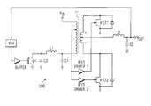
- DC-DC regulatorsmost commonly utlilize switching regulation and may use a push-pull arrangement as illustrated in FIG. 1 a with waveforms shown in FIG. 1 b.
- the pulse width modulated (PWM) driveralternately switches on and off power devices Q 1 and Q 2 to excite the transformer primary, and the transformer secondary feeds a self-commutating synchronous rectifier followed by an LC filter for output.
- the synchronous rectifieruses n-channel MOSFETs rather than diodes; this avoids the turn on voltage drop of diodes which can be significant for low output voltage power supplies.
- Resistor divider Rsenses the output voltage and feeds this back to the PWM driver.
- the PWM drivermay simply be an error amplifier (amplifying the difference between desired and actual output voltages) feeding one input of a comparator with a sawtooth voltage having a fixed frequency feeding the other comparator input; the comparator output would be the input signal for a driver for power device Q 1 and a similar phase-shifted comparator would be the input signal for a driver for power device Q 2 .
- FIG. 1 cillustrates such a possible half of a PWM driver.
- Switching power supplies for portable computers and other portable electronic equipmentgenerally benefit from higher switching frequencies because the size and weight of the magnetic portions (transformers and inductors) can be reduced. And the trend towards lower operating voltages for integrated circuits to reduce power consumption requires the output rectifiers of related power supplies have low on resistance and minimal voltage drop.
- JFETsJunction field effect transistors
- the driver for a JFETalso requires a negative power supply.
- injecting carriers from the gate of a JFET into the channel while the JFET is turned oncan lower the channel and drift region resistance (R ON ) and thereby minimizes ohmic losses.
- This “bipolar mode” of operationrequires a small positive voltage to forward bias the gate, and so the JFET driver would further require a small positive power supply. See Baliga, Modern Power Devices pp.175-182 (Krieger Publ., Malabar, Fla. 1992).
- the known drivers for JFET deviceshave problems including inefficient circuitry.
- FIGS. 2 a-bheuristically illustrate in perspective and cross sectional elevation views VFET 100 as including a source 102 , multifinger gate 104 , channel region 106 between the gate fingers, drain 108 , source contact 112 , gate contact 114 , and drain contact 118 .
- U.S. Pat. No. 5,231,037describes a method of fabrication for such VFETs.
- the present inventionprovides a resonant switching for a field effect transistor and associated circuits such as power supplies with synchronous output rectifiers.
- the resonant switching for a junction field effect transistorinvokes bipolar mode operation with a diode clamping of the gate.
- FIGS. 1 a-cshow known power switching circuitry and waveforms.
- FIGS. 2 a-billustrate a known vertical junction field effect transistor.
- FIG. 3is a circuit diagram of a first preferred embodiment driver.
- FIG. 4shows the timing for the operation of the embodiment of FIG. 3 .
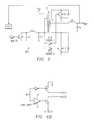
- FIG. 5shows a circuit diagram for a preferred embodiment power supply.
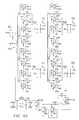
- FIGS. 6 a-dare circuit diagrams for another preferred embodiment power supply.
- FIG. 3shows in schematic view first preferred embodiment driver, generally denoted by reference numeral 300 , connected to drive the gate of vertical channel junction field effect transistor (VFET) 350 .
- Driver 300switches VFET 350 off and on by charging and discharging its gate.
- the DC-DC converter of FIG. 1 acould be constructed with synchronous rectifier transistors Q 3 and Q 4 as VFETs with gate drivers 300 . In this case the timing for the controllers 310 could derive from the PWM.
- Driver 300includes inductor 302 , switches 304 and 306 , and diode 308 .
- Controller 310opens and closes switches 304 and 306 to alternately apply ⁇ V B and a small positive voltage to the gate of VFET 350 .
- External input signals to controller 310determines the timing for the switching, and inductor 302 provides a resonant charging of the gate of VFET 350 by forming a series LC circuit with the gate-to-source capacitance of VFET 350 . With ground (or a small positive voltage) applied to its gate, VFET 350 turns on; and with the negative voltage ⁇ V B applied to its gate, VFET 350 turns off (is in a blocking state).
- the resonant VFET gate charginghas two advantages: it avoids some power dissipation during charging and it provides a small positive gate charge to increase the conductivity of the VFET channel (“biolar mode” of operation). Diode 308 holds the positive charge on the gate.
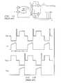
- FIG. 4is a timing diagram illustrating the operation of driver 300 .
- the upper portion of FIG. 4shows the timing of the signals from controller 310 to open and close switches 304 and 306 of driver 300
- lower portion of FIG. 4shows the voltage on the gate of VFET 350 and the current through inductor 302 .
- voltage ⁇ V Bapplies to the gate of VFET 350 and puts VFET 350 into its blocking state.
- controller 310closes switch 304 and opens switch 306 , this applies the ground voltage to the series LC circuit made of inductor 302 in series with diode 308 and the input capacitance of the gate of VFET 350 .
- This input capacitanceconsists primarily of the gate-to-source capacitance and initially has a charge of ⁇ V B .
- the current I through inductor 302 which charges the gate capacitanceinitially has the form
- Cis the gate capacitance and L is the inductance of inductor 302 .
- V ( t )⁇ V B cos[ t /( LC )]
- VFET 350is turning on.
- the rise time t 1equals ⁇ (LC)/2; so with a given gate capacitance C for VFET 350 , choose the inductance L to achieve a desired rise time.
- inductor 302to have an inductance of 0.1 ⁇ H.
- V Bequal to 3 volts, the maximum inductor current would be about 0.5 amp.
- VFET 350At time t 2 the gate voltage of VFET 350 has gone positive to forward bias the gate-source junction and shunt the inductor current to ground; that is, the gate voltage overshoots ground and goes positive due to the induced voltage from the inductor's magnetic field collapse.
- V jtypically about 0.8 volt for a VFET made of gallium arsenide, and the inductor current linearly decays toward 0 while diode 308 and the gate-to-source capacitance holds the gate voltage positive. That is, VFET 350 operates in “bipolar mode” without a separate power supply for the gate bias.
- the gate bias Vis self-adjusting.
- controller 310opens switch 304 and closes switch 306 to turn off VFET 350 .
- Closing switch 306connects the ⁇ V B supply directly to the gate of VFET 350 and rapidly charges it to ⁇ V B to turn off VFET 350 .
- the net effect of the on/off cycle with driver 300 switching VFET 350is a small positive bias on the VFET gate during turn on and thus bipolar mode operation without a separate positive bias power supply for the gate; rather a passive overshoot circuit (inductor) induces the desired voltage from the switching current charging the gate capacitance.
- the parameters such as the inductance L and resistance of inductor 302 , the current handling of switches 304 and 306 and of diode 308 , and the blocking voltage ⁇ V B , supplywill depend upon the characteristics of VFET 350 and the desired switching speed.
- the capacitance C of the gate and the on resistance R ON when clamped at V j , of VFET 350will depend upon the circuit requirements including the frequency of switching and current draw.
- controller 310 in FIG. 3need be no more than a conduit for the input signal to open and close the switches 304 and 306 .
- inductor current 302peaking at about 0.5 amp and the peak current through switch 306 quite large due to minimal series resistance, switches 304 and 306 may be fairly large and controller 310 may just consist of buffers to drive the switches.
- FIG. 3shows switches 304 and 306 as MOS field effect transistors, although any other type switch could be used.
- controller 310may be integrated with the ⁇ V B negative power supply (which could be a large capacitor charged by a charge pump) and provide a compact package including all of the components except inductor 302 .
- the MOS switchescould be one NMOS and one PMOS with the NMOS built in a well biased at ⁇ V B .
- FIG. 5schematically shows preferred embodiment power supply 500 as including inductor L 1 and capacitors C 1 and C 3 plus switching power MOSFET Q 1 between a dc supply V IN , and ground with transformer T 1 to couple power to a secondary circuit having VFET synchronous rectifiers with VFET drivers analogous to driver 300 .
- the outputhas low pass filter (inductor L 2 and capacitor C 2 ) and drives a voltage controlled oscillator (VCO) which drives power MOSFET Q 1 .
- VCOvoltage controlled oscillator
- Power supply 500operates as follows.
- VCOhas a free-running oscillation frequency of about 1 MHz and outputs a square wave.
- the VCO outputdrives the MOSFET Q 1 gate buffer to switch Q 1 between off and on at about 1 MHz. This yields a current through inductor L 1 and transformer T 1 primary which alternately increases and decreases and excites a changing polarity voltage in the secondary winding of T 1 .
- VFET Driver 1has VFET 1 in the blocking state and VFET Driver 2 has VFET 2 in the on state; whereas, when the polarity is the reverse of that shown in FIG. 5, the drivers have VFET 1 on and VFET 2 blocking.
- the VFETsprovide full wave rectification.
- VFETshave minimal voltage drop because of their low on-resistance in the bipolar mode due to the VFET drivers.
- a tap from the primary winding of transformer T 1sets the timing for the VFET drivers by sensing the polarity of the voltage across the primary winding.
- VCOchanges its oscillation frequency to change the secondary winding voltage magnitude.
- FIGS. 6 a-cschematically show a second preferred embodiment power supply which is analogous to power supply 500 .
- FIG. 6 aillustrates transformer primary winding 604 , inductor 606 , and power MOSFET 608 connected in series between +50 volts dc source 602 and ground; capacitors 610 and 612 connected to inductor 606 provide the capacitance for the resonant current build up and collapse.
- Inductor 606has an inductance of about 2.0 ⁇ H and capacitors 610 and 612 have capacitances of about 3000 pF and 1100 pF, respectively.
- the transformer secondaryconsists of eight center-tapped windings 621 - 628 combined in parallel pairs for a total of four +1.5 volts dc outputs 631 - 634 .
- Each of outputs 631 - 634has a low pass filter (inductor plus capacitor), and each of the center-tapped secondary windings has the center tap connected to the corresponding low pass filter and each of the two terminals connected to a VFET connected to ground.
- the sixteen VFETs( 641 - 656 ) have synchronous drivers (FIG. 6 c ) with the two VFETs in each pair driven to complementary states: one conducting and one blocking for full wave rectification.
- the VFET gate drive signalsare labelleld A-P.
- FIG. 6 bshows the voltage controlled oscillator which switches power MOSFET Q 1 off and on and adjusts its oscillation frequency according to feedback from the output +1.5 volts actual voltage.
- Cross-coupled NAND gates 661 and 662form a latch, plus each NAND gate has its output fedback through a diode to an input RC pulldown circuit ( 663 and 664 , respectively) which has a (manually adjustable) time constant of about 500 nsec.
- the cross-coupled NAND gatesform a square wave oscillator with a free running oscillation frequency of about 1 MHz.
- the output of the NAND gate oscillatordrives inverters 655 which in turn drive (via p-channel and n-channel MOSFETs) the gate of power MOSFET Q 1 to perform the current switching previously described.
- the righthand portion of FIG. 6 blabels the output of inverters 665 as V G
- the lefthand portion of FIG. 6 ashows V G driving pullup a p-channel MOSFET and pulldown n-channel MOSFETs which connect to the gate of power MOSFET 608 .
- the voltage controlled oscillator of FIG. 6 badjusts its oscillation frequency depending on the +1.5 volts output at the transformer secondaries by inputting the +1.5 volts to the inverting input of opamp 670 while the direct input is set by adjustable resistor divider 669 .
- the output of opamp 670feeds an input of NAND gate 672 , which with cross-coupled NAND gate 671 forms a latch, with the output of NAND gate 671 feeding (through an RC plus diode pullup circuit 673 ) an input of oscillator NAND gate 662 .
- the output of oscillator NAND gate 662feeds back (through RC plus diode pullup circuit 674 ) to the inputs of latch 671 - 672 .
- RC plus diode pullup circuits 673 and 674have time constants of about 50 nsec, so a high-to-low transition yields a low pulse of about 50 nsec and a low-to-high transition yields only a constant high.
- comparator ??outputs a low to NAND gate 672 through resistor 676 .
- RC plus diode pullup circuit 674passes a low 50 nsed pulse to NAND gate 671 and a high 50 nsec pulse to NAND gate 672 (resistor 676 provides the drop from the high of inverter 677 to the low sink of opamp 670 ). This sets and resets latch 671 - 672 to output a high pulse to RC plus diode pullup 673 and thus a 50 nsec low pulse to an input of NAND gate 662 .
- FIG. 6 cshows the drivers for VFETs 641 - 656 which are synchronized with the polarity of the voltages of the transformer secondary windings 621 - 628 by the tap from transformer primary winding 604 .
- FIG. 6 adenotes the primary tap output as V P /4 (i.e., the tap is across one quarter of the primary winding)
- FIG. 6 cshows V P /4, after passing a dc blocking capacitor and positive and negative limiting diodes, driving the direct input of comparator 680 with the inverting input at ground.
- NAND gate 681inverts the direct output of comparator 680 with a delay for low-to-high transitions
- NAND gate 682inverts the complementary output of comparator 680 also with a delay for low-to-high transitions.
- the direct and complementary outputs of comparator 680are then (when comparator 688 outputs a high) are inverted again by the NAND gates 683 and 684 , respectively, and become the inputs for VFET drivers 691 - 692 and 693 - 694 , respectively.
- Drivers 691 - 694all have the same structure, and FIG. 6 d illustrates this structure in simplified form.
- the OUT 2 outputconnects to the negative power supply ( ⁇ 2 volts) and the OUT 1 output floats; whereas, when the input is low, OUT 1 connects to ground and OUT 2 floats.
- the level shifterinsures turn off of the NMOS connected to the ⁇ 2 supply.
- the OUT 2 outputconnects directly to a VFET gate and the OUT 1 output connects through an inductor and diode to a VFET gate.
- thishas the same functionality as the circuit of FIG. 3, and the inductor plus diode provide the resonant positive VFET gate voltage for bipolar mode of operation.
- each of the transformer secondary windings 621 - 628one of the VFET gates (labelled A, C, E, G, I, K, M, and O) is driven by drivers 691 - 692 and the other VFET gate (labelled B, D, F, H, J, L, N, and P) is driven by drivers 693 - 694 .
- the drivers 691 - 692have outputs opposite the outputs of drivers 693 - 694 and full wave rectification of the voltages induced in the secondary windings occurs with the bipolar mode VFET providing a minimal voltage drop.
- comparator 688When comparator 688 provides a low output, all four drivers 691 - 694 has a high input, so ⁇ 2 volts applies to all VFET gates and all VFETs are in a blocking state. Thus the voltages induced in the secondary windings are rectified by the diodes paralleling the VFETs. Comparator 688 has a low output when the magnitude of the swings in V P /4 are too small to switch comparator 688 into a high output; adjustable resistor 689 sets the threshold for this switching.
- the preferred embodimentsmay be assembled from discrete components or the noninductor/transformer components could be totally or partially fabricated as a silicon integrated circuit.
- the negative voltagemay be supplied by a separate external power supply or by an on-chip charge pump.
- VFETs made of GaAs or other high mobility semiconductor materialsmay be discrete or integrated with diodes and small inductors; or integrated with silicon components via heteroepitaxy.
- the preferred embodimentsmay be varied in many ways while retaining one or more of the features of a FET gate charging current leading to a voltage overshoot in a passive resonant circuit with a diode to hold the FET gate at a bipolar mode voltage.
- the two switches(connecting to the turn on gate voltage and to the blocking gate voltage) could have open and closed time intervals which are overlapping or separated;
- the resonantly driven FETcould be a MOSFET or other insulated gate FET provided with a high breakdown gate dielectric or a gate-to-source bypass diode avoid gate dielectric breakdown, in this situation the two gate voltages may be V SS (typically ground) and V DD so that a boosted gate voltage (greater than V DD ) is obtained without a boost circuit;
- the resonant circuitinductor and gate capacitance plus diode
- the resonant circuitcould be varied such adding another capacitor in parallel with the gate capacitance, moving the diode to the other side of the inductor, inserting a second diode between ground and the inductor, providing a bypass diode from gate to source to limit the degree of bipolar operation, replacing the single inductor with several series or parallel or both inductors, omitting the diode if
Landscapes
- Engineering & Computer Science (AREA)
- Power Engineering (AREA)
- Dc-Dc Converters (AREA)
Abstract
Description
This application is a Divisional application of U.S. patent Ser. No. 08/331,435 filed on Oct. 31, 1994, now U.S. Pat. No. 6,208,535.
The following coassigned U.S. patent application discloses related subject matter: Ser. No. 08/159,353, filed Nov. 29, 1993.
This invention was made with Government support under Contract No. N66001-91-C-6008 awarded by the Department of the Navy. The government has certain rights in this invention.
The invention relates to electronic devices, and, more particularly, to junction field effect transistor drivers.
Electronic components, such as integrated circuits and displays, typically have power requirements which differ from the primary power supply characteristics. For example, portable computers may contain integrated circuits operating with a 3.3 volt DC supply and a backlit display screen operating at 1500 volts but the primary power consists of rechargeable batteries whose output voltage at full charge may be 5 volts and which drops exponentially as the batteries are discharged. Hence, electronic systems typically will include power supplies with AC-DC converters, DC-DC regulators, or DC-AC inverters to provide output power with the required characteristics.
DC-DC regulators most commonly utlilize switching regulation and may use a push-pull arrangement as illustrated in FIG. 1awith waveforms shown in FIG. 1b.Basically, the pulse width modulated (PWM) driver alternately switches on and off power devices Q1 and Q2 to excite the transformer primary, and the transformer secondary feeds a self-commutating synchronous rectifier followed by an LC filter for output. The synchronous rectifier uses n-channel MOSFETs rather than diodes; this avoids the turn on voltage drop of diodes which can be significant for low output voltage power supplies. Resistor divider R senses the output voltage and feeds this back to the PWM driver. If the output voltage is too low, then the PWM driver increases the duty cycles of Q1 and Q2, and conversely, if the output voltage is too high, the duty cycles of Q1 and Q2 are reduced. The PWM driver may simply be an error amplifier (amplifying the difference between desired and actual output voltages) feeding one input of a comparator with a sawtooth voltage having a fixed frequency feeding the other comparator input; the comparator output would be the input signal for a driver for power device Q1 and a similar phase-shifted comparator would be the input signal for a driver for power device Q2. FIG. 1cillustrates such a possible half of a PWM driver.
Switching power supplies for portable computers and other portable electronic equipment generally benefit from higher switching frequencies because the size and weight of the magnetic portions (transformers and inductors) can be reduced. And the trend towards lower operating voltages for integrated circuits to reduce power consumption requires the output rectifiers of related power supplies have low on resistance and minimal voltage drop.
Junction field effect transistors (JFETs) typically are depletion mode devices with n-type channels and require a negative gate voltage to pinch off the channel and turn off. Thus the driver for a JFET also requires a negative power supply. Further, injecting carriers from the gate of a JFET into the channel while the JFET is turned on can lower the channel and drift region resistance (RON) and thereby minimizes ohmic losses. This “bipolar mode” of operation requires a small positive voltage to forward bias the gate, and so the JFET driver would further require a small positive power supply. See Baliga, Modern Power Devices pp.175-182 (Krieger Publ., Malabar, Fla. 1992). Thus the known drivers for JFET devices have problems including inefficient circuitry.
JFETs made be made of gallium arsenide to lower RONdue to the higher electron mobility of gallium arsenide as compared to silicon. JFETs frequently have a vertical channel structure and thus may be called VFETs. FIGS. 2a-bheuristically illustrate in perspective and cross sectional elevation views VFET100 as including asource 102,multifinger gate 104,channel region 106 between the gate fingers,drain 108,source contact 112,gate contact 114, anddrain contact 118. U.S. Pat. No. 5,231,037 describes a method of fabrication for such VFETs.
The present invention provides a resonant switching for a field effect transistor and associated circuits such as power supplies with synchronous output rectifiers. The resonant switching for a junction field effect transistor invokes bipolar mode operation with a diode clamping of the gate.
This has the advantage of yielding bipolar mode operation without a separate bias power supply.
The drawings are schematic for clarity.
FIGS. 1a-cshow known power switching circuitry and waveforms.
FIGS. 2a-billustrate a known vertical junction field effect transistor.
FIG. 3 is a circuit diagram of a first preferred embodiment driver.
FIG. 4 shows the timing for the operation of the embodiment of FIG.3.
FIG. 5 shows a circuit diagram for a preferred embodiment power supply.
FIGS. 6a-dare circuit diagrams for another preferred embodiment power supply.
First preferred embodiment overview
FIG. 3 shows in schematic view first preferred embodiment driver, generally denoted byreference numeral 300, connected to drive the gate of vertical channel junction field effect transistor (VFET)350.Driver 300 switches VFET350 off and on by charging and discharging its gate. Indeed, the DC-DC converter of FIG. 1acould be constructed with synchronous rectifier transistors Q3 and Q4 as VFETs withgate drivers 300. In this case the timing for thecontrollers 310 could derive from the PWM.
Driver operation
FIG. 4 is a timing diagram illustrating the operation ofdriver 300. The upper portion of FIG. 4 shows the timing of the signals fromcontroller 310 to open andclose switches driver 300, and lower portion of FIG. 4 shows the voltage on the gate ofVFET 350 and the current throughinductor 302. In particular, presume that just prior totime 0switch 304 is open and switch306 is closed; thus voltage −VBapplies to the gate ofVFET 350 and putsVFET 350 into its blocking state. Then attime 0controller 310 closes switch304 and opensswitch 306, this applies the ground voltage to the series LC circuit made ofinductor 302 in series withdiode 308 and the input capacitance of the gate ofVFET 350. This input capacitance consists primarily of the gate-to-source capacitance and initially has a charge of −VB. Thus ignoring the voltage drop acrossdiode 308, the current I throughinductor 302 which charges the gate capacitance initially has the form
where C is the gate capacitance and L is the inductance ofinductor 302.
Similarly, the voltage on the gate ofVFET 350 initially rises as
and reaches 0 at time t1, in FIG. 4; at thistime VFET 350 is turning on. The rise time t1, equals π(LC)/2; so with a given gate capacitance C forVFET 350, choose the inductance L to achieve a desired rise time. For example, to achieve a rise time of 50 nanoseconds with a power VFET having an input gate capacitance of 2000 pF, chooseinductor 302 to have an inductance of 0.1 μH. With VBequal to 3 volts, the maximum inductor current would be about 0.5 amp. Thus a fairly small inductor for operating voltages of roughly 5 volts suffices.
In FIG. 4, at time t2the gate voltage ofVFET 350 has gone positive to forward bias the gate-source junction and shunt the inductor current to ground; that is, the gate voltage overshoots ground and goes positive due to the induced voltage from the inductor's magnetic field collapse. This clamps the gate voltage at Vj, typically about 0.8 volt for a VFET made of gallium arsenide, and the inductor current linearly decays toward 0 whilediode 308 and the gate-to-source capacitance holds the gate voltage positive. That is,VFET 350 operates in “bipolar mode” without a separate power supply for the gate bias. Furthermore, the gate bias V, is self-adjusting.
At time t3controller310 opensswitch 304 and closes switch306 to turn offVFET 350.Closing switch 306 connects the −VBsupply directly to the gate ofVFET 350 and rapidly charges it to −VBto turn offVFET 350.
The net effect of the on/off cycle withdriver 300 switchingVFET 350 is a small positive bias on the VFET gate during turn on and thus bipolar mode operation without a separate positive bias power supply for the gate; rather a passive overshoot circuit (inductor) induces the desired voltage from the switching current charging the gate capacitance.
The parameters such as the inductance L and resistance ofinductor 302, the current handling ofswitches diode 308, and the blocking voltage −VB, supply will depend upon the characteristics ofVFET 350 and the desired switching speed. The capacitance C of the gate and the on resistance RONwhen clamped at Vj, ofVFET 350 will depend upon the circuit requirements including the frequency of switching and current draw.
For a VFET of opposite doping type where a blocking gate voltage would be positive and a bipolar mode gate voltage would be small negative, the external supply would be at +VBand the inductor-induced voltage overshoot would apply in the same manner to yield a negative gate bias.
Controller
Generally,controller 310 in FIG. 3 need be no more than a conduit for the input signal to open and close theswitches switch 306 quite large due to minimal series resistance, switches304 and306 may be fairly large andcontroller 310 may just consist of buffers to drive the switches.
FIG. 3 showsswitches controller 310 may be integrated with the −VBnegative power supply (which could be a large capacitor charged by a charge pump) and provide a compact package including all of the components exceptinductor 302. Indeed, the MOS switches could be one NMOS and one PMOS with the NMOS built in a well biased at −VB.
Preferred embodiment power supply
FIG. 5 schematically shows preferredembodiment power supply 500 as including inductor L1 and capacitors C1 and C3 plus switching power MOSFET Q1 between a dc supply VIN, and ground with transformer T1 to couple power to a secondary circuit having VFET synchronous rectifiers with VFET drivers analogous todriver 300. The output has low pass filter (inductor L2 and capacitor C2) and drives a voltage controlled oscillator (VCO) which drives power MOSFET Q1. When Q1 switches closed, current resonantly builds up in inductor L1, and when Q1 opens the current resonantly collapses to 0. This provides varying current in the transformer primary winding to excite the transformer secondary winding with alternating polarity.
If the output voltage VOUTdiffers from the desired voltage, VCO changes its oscillation frequency to change the secondary winding voltage magnitude.
FIGS. 6a-cschematically show a second preferred embodiment power supply which is analogous topower supply 500. In particular, FIG. 6aillustrates transformer primary winding604,inductor 606, andpower MOSFET 608 connected in series between +50volts dc source 602 and ground;capacitors inductor 606 provide the capacitance for the resonant current build up and collapse.Inductor 606 has an inductance of about 2.0 μH andcapacitors
The transformer secondary consists of eight center-tapped windings621-628 combined in parallel pairs for a total of four +1.5 volts dc outputs631-634. Each of outputs631-634 has a low pass filter (inductor plus capacitor), and each of the center-tapped secondary windings has the center tap connected to the corresponding low pass filter and each of the two terminals connected to a VFET connected to ground. The sixteen VFETs (641-656) have synchronous drivers (FIG. 6c) with the two VFETs in each pair driven to complementary states: one conducting and one blocking for full wave rectification. The VFET gate drive signals are labelleld A-P.
FIG. 6bshows the voltage controlled oscillator which switches power MOSFET Q1 off and on and adjusts its oscillation frequency according to feedback from the output +1.5 volts actual voltage.Cross-coupled NAND gates inverters 655 which in turn drive (via p-channel and n-channel MOSFETs) the gate of power MOSFET Q1 to perform the current switching previously described. The righthand portion of FIG. 6blabels the output ofinverters 665 as VG, and the lefthand portion of FIG. 6ashows VGdriving pullup a p-channel MOSFET and pulldown n-channel MOSFETs which connect to the gate ofpower MOSFET 608.
The voltage controlled oscillator of FIG. 6badjusts its oscillation frequency depending on the +1.5 volts output at the transformer secondaries by inputting the +1.5 volts to the inverting input ofopamp 670 while the direct input is set byadjustable resistor divider 669. The output ofopamp 670 feeds an input ofNAND gate 672, which withcross-coupled NAND gate 671 forms a latch, with the output ofNAND gate 671 feeding (through an RC plus diode pullup circuit673) an input ofoscillator NAND gate 662. The output ofoscillator NAND gate 662 feeds back (through RC plus diode pullup circuit674) to the inputs of latch671-672. RC plusdiode pullup circuits resistor divider 669, comparator ?? outputs a low toNAND gate 672 throughresistor 676. Then whenoscillator NAND gate 662 makes a high-to-low transition, RC plusdiode pullup circuit 674 passes a low 50 nsed pulse toNAND gate 671 and a high 50 nsec pulse to NAND gate672 (resistor 676 provides the drop from the high ofinverter 677 to the low sink of opamp670). This sets and resets latch671-672 to output a high pulse to RC plusdiode pullup 673 and thus a 50 nsec low pulse to an input ofNAND gate 662. This switchesNAND gate 662 back high, and thereby shortens the usual 500 nsec low forNAND gate 662 to 50 nsec: changes the oscillation frequency and lessens the current buildup and collapse ininductor 606 and thus lessens the secondary voltage and eventually the +1.5 volts output. Hence, the feedback stabilizes the +1.5 volts output.
FIG. 6cshows the drivers for VFETs641-656 which are synchronized with the polarity of the voltages of the transformer secondary windings621-628 by the tap from transformer primary winding604. FIG. 6adenotes the primary tap output as VP/4 (i.e., the tap is across one quarter of the primary winding), and FIG. 6cshows VP/4, after passing a dc blocking capacitor and positive and negative limiting diodes, driving the direct input ofcomparator 680 with the inverting input at ground.NAND gate 681 inverts the direct output ofcomparator 680 with a delay for low-to-high transitions, andNAND gate 682 inverts the complementary output ofcomparator 680 also with a delay for low-to-high transitions. The direct and complementary outputs ofcomparator 680 are then (whencomparator 688 outputs a high) are inverted again by theNAND gates
As shown in FIG. 6c,the OUT2 output connects directly to a VFET gate and the OUT1 output connects through an inductor and diode to a VFET gate. Thus this has the same functionality as the circuit of FIG. 3, and the inductor plus diode provide the resonant positive VFET gate voltage for bipolar mode of operation.
In each of the transformer secondary windings621-628 one of the VFET gates (labelled A, C, E, G, I, K, M, and O) is driven by drivers691-692 and the other VFET gate (labelled B, D, F, H, J, L, N, and P) is driven by drivers693-694. Thus whencomparator 688 outputs a high, the drivers691-692 have outputs opposite the outputs of drivers693-694 and full wave rectification of the voltages induced in the secondary windings occurs with the bipolar mode VFET providing a minimal voltage drop.
Whencomparator 688 provides a low output, all four drivers691-694 has a high input, so −2 volts applies to all VFET gates and all VFETs are in a blocking state. Thus the voltages induced in the secondary windings are rectified by the diodes paralleling the VFETs.Comparator 688 has a low output when the magnitude of the swings in VP/4 are too small to switchcomparator 688 into a high output;adjustable resistor 689 sets the threshold for this switching.
Fabrication
The preferred embodiments may be assembled from discrete components or the noninductor/transformer components could be totally or partially fabricated as a silicon integrated circuit. The negative voltage may be supplied by a separate external power supply or by an on-chip charge pump. VFETs made of GaAs or other high mobility semiconductor materials may be discrete or integrated with diodes and small inductors; or integrated with silicon components via heteroepitaxy.
Modifications
The preferred embodiments may be varied in many ways while retaining one or more of the features of a FET gate charging current leading to a voltage overshoot in a passive resonant circuit with a diode to hold the FET gate at a bipolar mode voltage.
For example, the two switches (connecting to the turn on gate voltage and to the blocking gate voltage) could have open and closed time intervals which are overlapping or separated; the resonantly driven FET could be a MOSFET or other insulated gate FET provided with a high breakdown gate dielectric or a gate-to-source bypass diode avoid gate dielectric breakdown, in this situation the two gate voltages may be VSS(typically ground) and VDDso that a boosted gate voltage (greater than VDD) is obtained without a boost circuit; the resonant circuit (inductor and gate capacitance plus diode) could be varied such adding another capacitor in parallel with the gate capacitance, moving the diode to the other side of the inductor, inserting a second diode between ground and the inductor, providing a bypass diode from gate to source to limit the degree of bipolar operation, replacing the single inductor with several series or parallel or both inductors, omitting the diode if the switching frequency is high enough that the inductor collapse current keeps the FET in bipolar mode long enough, using other switches such as JFETs, MESFETs, bipolar transistors, and so forth; the materials the FET is made of can by varied, including heterojunction gates and ternary, quaternary or more element III-V semiconductor compounds; and the geometry of the JFET can be varied such as inclusion of a backgate.
Claims (5)
1. A dc power supply, comprising:
(a) a transformer with a primary winding and a secondary winding;
(b) a switched dc circuit connected to said primary winding;
(c) a dc output coupled to said secondary winding;
(d) a field effect transistor coupled between said secondary winding and ground; and
(e) a gate driver with an output connected to the gate of said field effect transistor, said gate driver including:
(i) first and second power supply inputs;
(ii) a first switch coupled between said first power supply input and said output;
(iii) a second switch coupled between said second power supply input and a passive overshoot circuit, said overshoot circuit coupled to said output; and
(iv) a switch input coupled to said first and second switches and synchronized with said switched dc circuit.
2. The dc power supply ofclaim 1 , wherein:
(a) said overshoot circuit includes an inductor.
3. The dc power supply ofclaim 2 , wherein:
(a) said overshoot circuit includes a diode in series with said inductor.
4. The dc power supply ofclaim 1 , further comprising:
(a) a lowpass filter connected between said second winding and said dc output.
5. The dc power supply ofclaim 1 , further comprising:
(a) a second field effect transistor coupled between said secondary winding and ground so that said dc output couples to said secondary winding between said field effect transistor and said second field effect transistor; and
(e) a second gate driver with a second output connected to the gate of said second field effect transistor, said second gate driver including:
(i) third and fourth power supply inputs;
(ii) a third switch coupled between said third power supply input and said output;
(iii) a fourth switch coupled between said fourth power supply input and a second passive overshoot circuit, said second overshoot circuit coupled to said second output; and
(iv) a second switch input coupled to said third and fourth switches and synchronized with said switched dc circuit.
Priority Applications (1)
| Application Number | Priority Date | Filing Date | Title |
|---|---|---|---|
| US09/788,803US6477065B2 (en) | 1994-10-31 | 2001-02-20 | Resonant gate driver |
Applications Claiming Priority (2)
| Application Number | Priority Date | Filing Date | Title |
|---|---|---|---|
| US08/331,435US6208535B1 (en) | 1994-10-31 | 1994-10-31 | Resonant gate driver |
| US09/788,803US6477065B2 (en) | 1994-10-31 | 2001-02-20 | Resonant gate driver |
Related Parent Applications (1)
| Application Number | Title | Priority Date | Filing Date |
|---|---|---|---|
| US08/331,435DivisionUS6208535B1 (en) | 1994-10-31 | 1994-10-31 | Resonant gate driver |
Publications (2)
| Publication Number | Publication Date |
|---|---|
| US20020110004A1 US20020110004A1 (en) | 2002-08-15 |
| US6477065B2true US6477065B2 (en) | 2002-11-05 |
Family
ID=23293955
Family Applications (2)
| Application Number | Title | Priority Date | Filing Date |
|---|---|---|---|
| US08/331,435Expired - LifetimeUS6208535B1 (en) | 1994-10-31 | 1994-10-31 | Resonant gate driver |
| US09/788,803Expired - Fee RelatedUS6477065B2 (en) | 1994-10-31 | 2001-02-20 | Resonant gate driver |
Family Applications Before (1)
| Application Number | Title | Priority Date | Filing Date |
|---|---|---|---|
| US08/331,435Expired - LifetimeUS6208535B1 (en) | 1994-10-31 | 1994-10-31 | Resonant gate driver |
Country Status (1)
| Country | Link |
|---|---|
| US (2) | US6208535B1 (en) |
Cited By (106)
| Publication number | Priority date | Publication date | Assignee | Title |
|---|---|---|---|---|
| US6807071B1 (en)* | 2003-07-28 | 2004-10-19 | Delta Electronics Inc. | Transformer isolated driver |
| US20050168203A1 (en)* | 2004-01-29 | 2005-08-04 | Enpirion, Incorporated | Driver for a power converter and a method of driving a switch thereof |
| US6946885B1 (en)* | 2003-05-19 | 2005-09-20 | The United States Of America As Represented By The United States Department Of Energy | Ripple gate drive circuit for fast operation of series connected IGBTs |
| US20060038238A1 (en)* | 2004-08-23 | 2006-02-23 | Lotfi Ashraf W | Integrated circuit incorporating higher voltage devices and low voltage devices therein |
| US20060226478A1 (en)* | 2005-03-29 | 2006-10-12 | Brar Berinder P S | Semiconductor device having a lateral channel and contacts on opposing surfaces thereof |
| US20060226477A1 (en)* | 2005-03-29 | 2006-10-12 | Brar Berinder P S | Substrate driven field-effect transistor |
| US20060226819A1 (en)* | 2005-03-31 | 2006-10-12 | Ming Xu | Self-driven scheme for synchronous rectifier |
| US20060255360A1 (en)* | 2005-05-13 | 2006-11-16 | Brar Berinder P S | Semiconductor device having multiple lateral channels and method of forming the same |
| US7173831B1 (en)* | 2005-09-23 | 2007-02-06 | Intel Corporation | Power converter having a primary side switching circuit |
| US20070045765A1 (en)* | 2005-08-25 | 2007-03-01 | Brar Berinder P | Semiconductor device having substrate-driven field-effect transistor and schottky diode and method of forming the same |
| US20070069286A1 (en)* | 2005-09-27 | 2007-03-29 | Brar Berinder P S | Semiconductor device having an interconnect with sloped walls and method of forming the same |
| US20070187717A1 (en)* | 2005-05-13 | 2007-08-16 | Coldwatt, Inc. | Semiconductor device having reduced on-resistance and method of forming the same |
| US20070210777A1 (en)* | 2006-03-06 | 2007-09-13 | Cervera Pedro A | Controller for a power converter and method of operating the same |
| US7280026B2 (en) | 2002-04-18 | 2007-10-09 | Coldwatt, Inc. | Extended E matrix integrated magnetics (MIM) core |
| US7285876B1 (en) | 2006-05-01 | 2007-10-23 | Raytheon Company | Regenerative gate drive circuit for power MOSFET |
| US20070262806A1 (en)* | 2006-05-11 | 2007-11-15 | Thummalapally Damodar R | Level shifting circuit having junction field effect transistors |
| US7298118B2 (en) | 2005-02-23 | 2007-11-20 | Coldwatt, Inc. | Power converter employing a tapped inductor and integrated magnetics and method of operating the same |
| US20070296028A1 (en)* | 2006-06-21 | 2007-12-27 | Brar Berinder P S | Vertical Field-Effect Transistor and Method of Forming the Same |
| US20070298564A1 (en)* | 2006-06-21 | 2007-12-27 | Brar Berinder P S | Vertical Field-Effect Transistor and Method of Forming the Same |
| US7321283B2 (en) | 2004-08-19 | 2008-01-22 | Coldwatt, Inc. | Vertical winding structures for planar magnetic switched-mode power converters |
| US20080018366A1 (en)* | 2006-07-20 | 2008-01-24 | Enpirion, Inc. | Driver for switch and a method of driving the same |
| US20080048173A1 (en)* | 2005-08-25 | 2008-02-28 | Sadaka Mariam G | Semiconductor Device Including a Lateral Field-Effect Transistor and Schottky Diode |
| US20080094114A1 (en)* | 2006-10-20 | 2008-04-24 | Mirmira Ramarao Dwarakanath | Controller including a sawtooth generator and method of operating the same |
| US7385375B2 (en) | 2005-02-23 | 2008-06-10 | Coldwatt, Inc. | Control circuit for a depletion mode switch and method of operating the same |
| US7417875B2 (en) | 2005-02-08 | 2008-08-26 | Coldwatt, Inc. | Power converter employing integrated magnetics with a current multiplier rectifier and method of operating the same |
| US7427910B2 (en) | 2004-08-19 | 2008-09-23 | Coldwatt, Inc. | Winding structure for efficient switch-mode power converters |
| US20090167267A1 (en)* | 2007-12-27 | 2009-07-02 | Mirmira Ramarao Dwarakanath | Power Converter with Monotonic Turn-On for Pre-Charged Output Capacitor |
| US7558083B2 (en) | 1997-01-24 | 2009-07-07 | Synqor, Inc. | High efficiency power converter |
| US7564702B2 (en) | 1997-01-24 | 2009-07-21 | Synqor, Inc. | High efficiency power converter |
| US20090261791A1 (en)* | 2008-04-16 | 2009-10-22 | Lopata Douglas D | Power Converter with Power Switch Operable in Controlled Current Mode |
| US7667986B2 (en) | 2006-12-01 | 2010-02-23 | Flextronics International Usa, Inc. | Power system with power converters having an adaptive controller |
| US20100052052A1 (en)* | 2004-01-29 | 2010-03-04 | Enpirion, Incorporated | Integrated Circuit with a Laterally Diffused Metal Oxide Semiconductor Device and Method of Forming the Same |
| US7675759B2 (en) | 2006-12-01 | 2010-03-09 | Flextronics International Usa, Inc. | Power system with power converters having an adaptive controller |
| US7675758B2 (en) | 2006-12-01 | 2010-03-09 | Flextronics International Usa, Inc. | Power converter with an adaptive controller and method of operating the same |
| US20100118565A1 (en)* | 2008-11-11 | 2010-05-13 | Roman Stuler | Method of forming a series resonant switching power supply control circuit and structure therefor |
| US7876191B2 (en) | 2005-02-23 | 2011-01-25 | Flextronics International Usa, Inc. | Power converter employing a tapped inductor and integrated magnetics and method of operating the same |
| US7889517B2 (en) | 2006-12-01 | 2011-02-15 | Flextronics International Usa, Inc. | Power system with power converters having an adaptive controller |
| US7906941B2 (en) | 2007-06-19 | 2011-03-15 | Flextronics International Usa, Inc. | System and method for estimating input power for a power processing circuit |
| US20110157921A1 (en)* | 2009-12-31 | 2011-06-30 | Cheng-Yi Lo | Multi-output dc-to-dc conversion apparatus with voltage-stabilizing function |
| US8125205B2 (en) | 2006-08-31 | 2012-02-28 | Flextronics International Usa, Inc. | Power converter employing regulators with a coupled inductor |
| US8212317B2 (en) | 2004-01-29 | 2012-07-03 | Enpirion, Inc. | Integrated circuit with a laterally diffused metal oxide semiconductor device and method of forming the same |
| US8212316B2 (en) | 2004-01-29 | 2012-07-03 | Enpirion, Inc. | Integrated circuit with a laterally diffused metal oxide semiconductor device and method of forming the same |
| US8212315B2 (en) | 2004-01-29 | 2012-07-03 | Enpirion, Inc. | Integrated circuit with a laterally diffused metal oxide semiconductor device and method of forming the same |
| US8253197B2 (en) | 2004-01-29 | 2012-08-28 | Enpirion, Inc. | Integrated circuit with a laterally diffused metal oxide semiconductor device and method of forming the same |
| US8253195B2 (en) | 2004-01-29 | 2012-08-28 | Enpirion, Inc. | Integrated circuit with a laterally diffused metal oxide semiconductor device and method of forming the same |
| US8410769B2 (en) | 2008-04-16 | 2013-04-02 | Enpirion, Inc. | Power converter with controller operable in selected modes of operation |
| US8415737B2 (en) | 2006-06-21 | 2013-04-09 | Flextronics International Usa, Inc. | Semiconductor device with a pillar region and method of forming the same |
| US8502520B2 (en) | 2007-03-14 | 2013-08-06 | Flextronics International Usa, Inc | Isolated power converter |
| US8514593B2 (en) | 2009-06-17 | 2013-08-20 | Power Systems Technologies, Ltd. | Power converter employing a variable switching frequency and a magnetic device with a non-uniform gap |
| US8520420B2 (en) | 2009-12-18 | 2013-08-27 | Power Systems Technologies, Ltd. | Controller for modifying dead time between switches in a power converter |
| US8520414B2 (en) | 2009-01-19 | 2013-08-27 | Power Systems Technologies, Ltd. | Controller for a power converter |
| US8541991B2 (en) | 2008-04-16 | 2013-09-24 | Enpirion, Inc. | Power converter with controller operable in selected modes of operation |
| US8638578B2 (en) | 2009-08-14 | 2014-01-28 | Power System Technologies, Ltd. | Power converter including a charge pump employable in a power adapter |
| US8643222B2 (en) | 2009-06-17 | 2014-02-04 | Power Systems Technologies Ltd | Power adapter employing a power reducer |
| US8686698B2 (en) | 2008-04-16 | 2014-04-01 | Enpirion, Inc. | Power converter with controller operable in selected modes of operation |
| US8692532B2 (en) | 2008-04-16 | 2014-04-08 | Enpirion, Inc. | Power converter with controller operable in selected modes of operation |
| US8698463B2 (en) | 2008-12-29 | 2014-04-15 | Enpirion, Inc. | Power converter with a dynamically configurable controller based on a power conversion mode |
| US8716790B2 (en) | 2004-01-29 | 2014-05-06 | Enpirion, Inc. | Laterally diffused metal oxide semiconductor device and method of forming the same |
| US8749995B2 (en) | 2011-03-29 | 2014-06-10 | Texas Instruments Incorporated | Single-pulse resonant gate driver for driving switches in resonant isolated converters and other systems |
| US8767418B2 (en) | 2010-03-17 | 2014-07-01 | Power Systems Technologies Ltd. | Control system for a power converter and method of operating the same |
| US8787043B2 (en) | 2010-01-22 | 2014-07-22 | Power Systems Technologies, Ltd. | Controller for a power converter and method of operating the same |
| US8792257B2 (en) | 2011-03-25 | 2014-07-29 | Power Systems Technologies, Ltd. | Power converter with reduced power dissipation |
| US8792256B2 (en) | 2012-01-27 | 2014-07-29 | Power Systems Technologies Ltd. | Controller for a switch and method of operating the same |
| US8867295B2 (en) | 2010-12-17 | 2014-10-21 | Enpirion, Inc. | Power converter for a memory module |
| US8976549B2 (en) | 2009-12-03 | 2015-03-10 | Power Systems Technologies, Ltd. | Startup circuit including first and second Schmitt triggers and power converter employing the same |
| US9019061B2 (en) | 2009-03-31 | 2015-04-28 | Power Systems Technologies, Ltd. | Magnetic device formed with U-shaped core pieces and power converter employing the same |
| US9077248B2 (en) | 2009-06-17 | 2015-07-07 | Power Systems Technologies Ltd | Start-up circuit for a power adapter |
| US9088216B2 (en) | 2009-01-19 | 2015-07-21 | Power Systems Technologies, Ltd. | Controller for a synchronous rectifier switch |
| US9099232B2 (en) | 2012-07-16 | 2015-08-04 | Power Systems Technologies Ltd. | Magnetic device and power converter employing the same |
| US9106130B2 (en) | 2012-07-16 | 2015-08-11 | Power Systems Technologies, Inc. | Magnetic device and power converter employing the same |
| US9190898B2 (en) | 2012-07-06 | 2015-11-17 | Power Systems Technologies, Ltd | Controller for a power converter and method of operating the same |
| US9197132B2 (en) | 2006-12-01 | 2015-11-24 | Flextronics International Usa, Inc. | Power converter with an adaptive controller and method of operating the same |
| US9214264B2 (en) | 2012-07-16 | 2015-12-15 | Power Systems Technologies, Ltd. | Magnetic device and power converter employing the same |
| US9240712B2 (en) | 2012-12-13 | 2016-01-19 | Power Systems Technologies Ltd. | Controller including a common current-sense device for power switches of a power converter |
| US9246391B2 (en) | 2010-01-22 | 2016-01-26 | Power Systems Technologies Ltd. | Controller for providing a corrected signal to a sensed peak current through a circuit element of a power converter |
| US9246390B2 (en) | 2008-04-16 | 2016-01-26 | Enpirion, Inc. | Power converter with controller operable in selected modes of operation |
| US9299691B2 (en) | 2012-11-30 | 2016-03-29 | Enpirion, Inc. | Semiconductor device including alternating source and drain regions, and respective source and drain metallic strips |
| US9300206B2 (en) | 2013-11-15 | 2016-03-29 | Power Systems Technologies Ltd. | Method for estimating power of a power converter |
| US9379629B2 (en) | 2012-07-16 | 2016-06-28 | Power Systems Technologies, Ltd. | Magnetic device and power converter employing the same |
| US9509217B2 (en) | 2015-04-20 | 2016-11-29 | Altera Corporation | Asymmetric power flow controller for a power converter and method of operating the same |
| US9536938B1 (en) | 2013-11-27 | 2017-01-03 | Altera Corporation | Semiconductor device including a resistor metallic layer and method of forming the same |
| US9548714B2 (en) | 2008-12-29 | 2017-01-17 | Altera Corporation | Power converter with a dynamically configurable controller and output filter |
| US9673192B1 (en) | 2013-11-27 | 2017-06-06 | Altera Corporation | Semiconductor device including a resistor metallic layer and method of forming the same |
| US9847581B2 (en) | 2009-06-17 | 2017-12-19 | L. Pierre de Rochemont | Frequency-selective dipole antennas |
| US9882274B2 (en) | 2004-10-01 | 2018-01-30 | L. Pierre de Rochemont | Ceramic antenna module and methods of manufacture thereof |
| US9881915B2 (en) | 2010-08-23 | 2018-01-30 | L. Pierre de Rochemont | Power FET with a resonant transistor gate |
| US10020739B2 (en) | 2014-03-27 | 2018-07-10 | Altera Corporation | Integrated current replicator and method of operating the same |
| US10103627B2 (en) | 2015-02-26 | 2018-10-16 | Altera Corporation | Packaged integrated circuit including a switch-mode regulator and method of forming the same |
| US10199950B1 (en) | 2013-07-02 | 2019-02-05 | Vlt, Inc. | Power distribution architecture with series-connected bus converter |
| USD940149S1 (en) | 2017-06-08 | 2022-01-04 | Insulet Corporation | Display screen with a graphical user interface |
| USD977502S1 (en) | 2020-06-09 | 2023-02-07 | Insulet Corporation | Display screen with graphical user interface |
| US11857763B2 (en) | 2016-01-14 | 2024-01-02 | Insulet Corporation | Adjusting insulin delivery rates |
| US11865299B2 (en) | 2008-08-20 | 2024-01-09 | Insulet Corporation | Infusion pump systems and methods |
| US11929158B2 (en) | 2016-01-13 | 2024-03-12 | Insulet Corporation | User interface for diabetes management system |
| USD1020794S1 (en) | 2018-04-02 | 2024-04-02 | Bigfoot Biomedical, Inc. | Medication delivery device with icons |
| USD1024090S1 (en) | 2019-01-09 | 2024-04-23 | Bigfoot Biomedical, Inc. | Display screen or portion thereof with graphical user interface associated with insulin delivery |
| US11969579B2 (en) | 2017-01-13 | 2024-04-30 | Insulet Corporation | Insulin delivery methods, systems and devices |
| US12042630B2 (en) | 2017-01-13 | 2024-07-23 | Insulet Corporation | System and method for adjusting insulin delivery |
| US12064591B2 (en) | 2013-07-19 | 2024-08-20 | Insulet Corporation | Infusion pump system and method |
| US12076160B2 (en) | 2016-12-12 | 2024-09-03 | Insulet Corporation | Alarms and alerts for medication delivery devices and systems |
| US12097355B2 (en) | 2023-01-06 | 2024-09-24 | Insulet Corporation | Automatically or manually initiated meal bolus delivery with subsequent automatic safety constraint relaxation |
| US12106837B2 (en) | 2016-01-14 | 2024-10-01 | Insulet Corporation | Occlusion resolution in medication delivery devices, systems, and methods |
| US12318577B2 (en) | 2017-01-13 | 2025-06-03 | Insulet Corporation | System and method for adjusting insulin delivery |
| US12318594B2 (en) | 2016-05-26 | 2025-06-03 | Insulet Corporation | On-body interlock for drug delivery device |
| US12343502B2 (en) | 2017-01-13 | 2025-07-01 | Insulet Corporation | System and method for adjusting insulin delivery |
| US12383166B2 (en) | 2016-05-23 | 2025-08-12 | Insulet Corporation | Insulin delivery system and methods with risk-based set points |
Families Citing this family (32)
| Publication number | Priority date | Publication date | Assignee | Title |
|---|---|---|---|---|
| US7116728B2 (en)* | 2001-05-25 | 2006-10-03 | Matsushita Electric Industrial Co., Ltd. | Quadrature alignment in communications receivers using dual delay lines |
| US6650169B2 (en)* | 2001-10-01 | 2003-11-18 | Koninklijke Philips Electronics N.V. | Gate driver apparatus having an energy recovering circuit |
| US6992520B1 (en)* | 2002-01-22 | 2006-01-31 | Edward Herbert | Gate drive method and apparatus for reducing losses in the switching of MOSFETs |
| US8749054B2 (en) | 2010-06-24 | 2014-06-10 | L. Pierre de Rochemont | Semiconductor carrier with vertical power FET module |
| DE10212869A1 (en)* | 2002-03-22 | 2003-09-18 | Siemens Ag | Drive circuit for barrier layer field effect transistor, has source controlled so barrier control current or voltage adopts higher then lower value sufficient to block FET when FET switched off |
| DE10212863B4 (en)* | 2002-03-22 | 2006-06-08 | Siemens Ag | Drive circuit for a junction field effect transistor |
| EP1654804B1 (en)* | 2003-08-01 | 2007-01-17 | Philips Intellectual Property & Standards GmbH | High frequency control of a semiconductor switch |
| US8715839B2 (en) | 2005-06-30 | 2014-05-06 | L. Pierre de Rochemont | Electrical components and method of manufacture |
| CA2567312A1 (en)* | 2005-11-04 | 2007-05-04 | Yan-Fei Liu | Resonant gate drive circuit with centre-tapped transformer |
| US8354294B2 (en) | 2006-01-24 | 2013-01-15 | De Rochemont L Pierre | Liquid chemical deposition apparatus and process and products therefrom |
| US8595041B2 (en)* | 2006-02-07 | 2013-11-26 | Sap Ag | Task responsibility system |
| US8526206B2 (en)* | 2007-07-09 | 2013-09-03 | Power Concepts Nz Limited | Drive circuit |
| US7528590B2 (en)* | 2007-10-01 | 2009-05-05 | Silicon Laboratories Inc. | DC/DC boost converter with pulse skipping circuitry |
| US7987928B2 (en)* | 2007-10-09 | 2011-08-02 | Pdti Holdings, Llc | Injection system and method comprising an impactor motive device |
| US9300203B2 (en) | 2007-12-10 | 2016-03-29 | Clevx, Llc | Battery power supply with automatic load sensing |
| US20120049800A1 (en) | 2010-08-25 | 2012-03-01 | Clevx, Llc | Power supply system with automatic sensing mechanism and method of operation thereof |
| US8922347B1 (en) | 2009-06-17 | 2014-12-30 | L. Pierre de Rochemont | R.F. energy collection circuit for wireless devices |
| US8080805B2 (en)* | 2010-03-09 | 2011-12-20 | International Business Machines Corporation | FET radiation monitor |
| WO2011119850A2 (en)* | 2010-03-26 | 2011-09-29 | Power Systems Technologies, Ltd. | Power adapter having a universal serial bus hub |
| JP2013530625A (en)* | 2010-05-10 | 2013-07-25 | マイクロセミ コーポレィション | Junction gate driver |
| US8552708B2 (en) | 2010-06-02 | 2013-10-08 | L. Pierre de Rochemont | Monolithic DC/DC power management module with surface FET |
| US9023493B2 (en) | 2010-07-13 | 2015-05-05 | L. Pierre de Rochemont | Chemically complex ablative max-phase material and method of manufacture |
| EP2636069B1 (en) | 2010-11-03 | 2021-07-07 | L. Pierre De Rochemont | Semiconductor chip carriers with monolithically integrated quantum dot devices and method of manufacture thereof |
| US8614111B2 (en) | 2011-07-25 | 2013-12-24 | International Business Machines Corporation | Fully depleted silicon on insulator neutron detector |
| US8361829B1 (en) | 2011-08-31 | 2013-01-29 | International Business Machines Corporation | On-chip radiation dosimeter |
| RU2563966C1 (en)* | 2011-11-02 | 2015-09-27 | Мицубиси Электрик Корпорейшн | Exciter for power conversion device and method for exciting power conversion device |
| KR101397749B1 (en) | 2012-12-28 | 2014-05-20 | 삼성전기주식회사 | Switching mode power supply and its controlling method |
| WO2016017257A1 (en)* | 2014-07-31 | 2016-02-04 | 株式会社村田製作所 | Power conversion device and wireless power transmission system |
| US10038442B2 (en) | 2015-06-30 | 2018-07-31 | Fronius International Gmbh | Circuit arrangement for controlling a transistor |
| US9947664B1 (en) | 2016-10-14 | 2018-04-17 | International Business Machines Corporation | Semiconductor device and method of forming the semiconductor device |
| CN108075623B (en)* | 2016-11-09 | 2020-04-21 | 致茂电子(苏州)有限公司 | Clamp Control Circuit |
| US12057711B2 (en)* | 2018-02-19 | 2024-08-06 | Naptilus Technology Lab, S.L. | Tuner and rectifier circuit for wireless power receiver |
Citations (3)
| Publication number | Priority date | Publication date | Assignee | Title |
|---|---|---|---|---|
| US5528480A (en)* | 1994-04-28 | 1996-06-18 | Elonex Technologies, Inc. | Highly efficient rectifying and converting circuit for computer power supplies |
| US5726869A (en)* | 1995-10-05 | 1998-03-10 | Fujitsu Limited | Synchronous rectifier type DC-to-DC converter in which a saturable inductive device is connected in series with a secondary-side switching device |
| US5995381A (en)* | 1997-07-08 | 1999-11-30 | Media Technology Corporation | Pulse width modulation controlled switching regulator |
Family Cites Families (5)
| Publication number | Priority date | Publication date | Assignee | Title |
|---|---|---|---|---|
| JPH03286619A (en)* | 1990-04-02 | 1991-12-17 | Mitsubishi Electric Corp | Gate driver circuit for isolation gate type semiconductor device and flash controller using same circuit |
| US5265003A (en)* | 1990-07-25 | 1993-11-23 | Power Trends | Miniaturized switching power supply with programmed level gate drive |
| US5296765A (en)* | 1992-03-20 | 1994-03-22 | Siliconix Incorporated | Driver circuit for sinking current to two supply voltages |
| US5328845A (en)* | 1992-03-27 | 1994-07-12 | Universal Foods Corporation | Fungal negative microorganism capable of producing high levels of beta-carotene |
| US5264736A (en)* | 1992-04-28 | 1993-11-23 | Raytheon Company | High frequency resonant gate drive for a power MOSFET |
- 1994
- 1994-10-31USUS08/331,435patent/US6208535B1/ennot_activeExpired - Lifetime
- 2001
- 2001-02-20USUS09/788,803patent/US6477065B2/ennot_activeExpired - Fee Related
Patent Citations (3)
| Publication number | Priority date | Publication date | Assignee | Title |
|---|---|---|---|---|
| US5528480A (en)* | 1994-04-28 | 1996-06-18 | Elonex Technologies, Inc. | Highly efficient rectifying and converting circuit for computer power supplies |
| US5726869A (en)* | 1995-10-05 | 1998-03-10 | Fujitsu Limited | Synchronous rectifier type DC-to-DC converter in which a saturable inductive device is connected in series with a secondary-side switching device |
| US5995381A (en)* | 1997-07-08 | 1999-11-30 | Media Technology Corporation | Pulse width modulation controlled switching regulator |
Cited By (170)
| Publication number | Priority date | Publication date | Assignee | Title |
|---|---|---|---|---|
| US7564702B2 (en) | 1997-01-24 | 2009-07-21 | Synqor, Inc. | High efficiency power converter |
| US8493751B2 (en) | 1997-01-24 | 2013-07-23 | Synqor, Inc. | High efficiency power converter |
| US7558083B2 (en) | 1997-01-24 | 2009-07-07 | Synqor, Inc. | High efficiency power converter |
| US8023290B2 (en) | 1997-01-24 | 2011-09-20 | Synqor, Inc. | High efficiency power converter |
| US9143042B2 (en) | 1997-01-24 | 2015-09-22 | Synqor, Inc. | High efficiency power converter |
| US8134443B2 (en) | 2002-04-18 | 2012-03-13 | Flextronics International Usa, Inc. | Extended E matrix integrated magnetics (MIM) core |
| US7633369B2 (en) | 2002-04-18 | 2009-12-15 | Flextronics International Usa, Inc. | Extended E matrix integrated magnetics (MIM) core |
| US7280026B2 (en) | 2002-04-18 | 2007-10-09 | Coldwatt, Inc. | Extended E matrix integrated magnetics (MIM) core |
| US6946885B1 (en)* | 2003-05-19 | 2005-09-20 | The United States Of America As Represented By The United States Department Of Energy | Ripple gate drive circuit for fast operation of series connected IGBTs |
| US6807071B1 (en)* | 2003-07-28 | 2004-10-19 | Delta Electronics Inc. | Transformer isolated driver |
| US8253197B2 (en) | 2004-01-29 | 2012-08-28 | Enpirion, Inc. | Integrated circuit with a laterally diffused metal oxide semiconductor device and method of forming the same |
| US9680008B2 (en) | 2004-01-29 | 2017-06-13 | Empirion, Inc. | Laterally diffused metal oxide semiconductor device and method of forming the same |
| US8212316B2 (en) | 2004-01-29 | 2012-07-03 | Enpirion, Inc. | Integrated circuit with a laterally diffused metal oxide semiconductor device and method of forming the same |
| US20100052052A1 (en)* | 2004-01-29 | 2010-03-04 | Enpirion, Incorporated | Integrated Circuit with a Laterally Diffused Metal Oxide Semiconductor Device and Method of Forming the Same |
| US8987815B2 (en) | 2004-01-29 | 2015-03-24 | Enpirion, Inc. | Integrated circuit with a laterally diffused metal oxide semiconductor device and method of forming the same |
| US8253196B2 (en) | 2004-01-29 | 2012-08-28 | Enpirion, Inc. | Integrated circuit with a laterally diffused metal oxide semiconductor device and method of forming the same |
| US8212315B2 (en) | 2004-01-29 | 2012-07-03 | Enpirion, Inc. | Integrated circuit with a laterally diffused metal oxide semiconductor device and method of forming the same |
| US8212317B2 (en) | 2004-01-29 | 2012-07-03 | Enpirion, Inc. | Integrated circuit with a laterally diffused metal oxide semiconductor device and method of forming the same |
| US7710093B2 (en) | 2004-01-29 | 2010-05-04 | Enpirion, Inc. | Driver for a power converter and a method of driving a switch thereof |
| US7330017B2 (en)* | 2004-01-29 | 2008-02-12 | Enpirion, Inc. | Driver for a power converter and a method of driving a switch thereof |
| US8716790B2 (en) | 2004-01-29 | 2014-05-06 | Enpirion, Inc. | Laterally diffused metal oxide semiconductor device and method of forming the same |
| US8633540B2 (en) | 2004-01-29 | 2014-01-21 | Enpirion, Inc. | Integrated circuit with a laterally diffused metal oxide semiconductor device and method of forming the same |
| US8253195B2 (en) | 2004-01-29 | 2012-08-28 | Enpirion, Inc. | Integrated circuit with a laterally diffused metal oxide semiconductor device and method of forming the same |
| US20050168203A1 (en)* | 2004-01-29 | 2005-08-04 | Enpirion, Incorporated | Driver for a power converter and a method of driving a switch thereof |
| US7321283B2 (en) | 2004-08-19 | 2008-01-22 | Coldwatt, Inc. | Vertical winding structures for planar magnetic switched-mode power converters |
| US7554430B2 (en) | 2004-08-19 | 2009-06-30 | Flextronics International Usa, Inc. | Vertical winding structures for planar magnetic switched-mode power converters |
| US7427910B2 (en) | 2004-08-19 | 2008-09-23 | Coldwatt, Inc. | Winding structure for efficient switch-mode power converters |
| US7214985B2 (en) | 2004-08-23 | 2007-05-08 | Enpirion, Inc. | Integrated circuit incorporating higher voltage devices and low voltage devices therein |
| US20060038238A1 (en)* | 2004-08-23 | 2006-02-23 | Lotfi Ashraf W | Integrated circuit incorporating higher voltage devices and low voltage devices therein |
| US9882274B2 (en) | 2004-10-01 | 2018-01-30 | L. Pierre de Rochemont | Ceramic antenna module and methods of manufacture thereof |
| US10673130B2 (en) | 2004-10-01 | 2020-06-02 | L. Pierre de Rochemont | Ceramic antenna module and methods of manufacture thereof |
| US7417875B2 (en) | 2005-02-08 | 2008-08-26 | Coldwatt, Inc. | Power converter employing integrated magnetics with a current multiplier rectifier and method of operating the same |
| US7675764B2 (en) | 2005-02-08 | 2010-03-09 | Flextronics International Usa, Inc. | Power converter employing integrated magnetics with a current multiplier rectifier and method of operating the same |
| US7298118B2 (en) | 2005-02-23 | 2007-11-20 | Coldwatt, Inc. | Power converter employing a tapped inductor and integrated magnetics and method of operating the same |
| US7385375B2 (en) | 2005-02-23 | 2008-06-10 | Coldwatt, Inc. | Control circuit for a depletion mode switch and method of operating the same |
| US7876191B2 (en) | 2005-02-23 | 2011-01-25 | Flextronics International Usa, Inc. | Power converter employing a tapped inductor and integrated magnetics and method of operating the same |
| US7439557B2 (en) | 2005-03-29 | 2008-10-21 | Coldwatt, Inc. | Semiconductor device having a lateral channel and contacts on opposing surfaces thereof |
| US7439556B2 (en) | 2005-03-29 | 2008-10-21 | Coldwatt, Inc. | Substrate driven field-effect transistor |
| US20060226477A1 (en)* | 2005-03-29 | 2006-10-12 | Brar Berinder P S | Substrate driven field-effect transistor |
| US20060226478A1 (en)* | 2005-03-29 | 2006-10-12 | Brar Berinder P S | Semiconductor device having a lateral channel and contacts on opposing surfaces thereof |
| US7265525B2 (en)* | 2005-03-31 | 2007-09-04 | Virginia Tech Intellectual Properties, Inc. | Self-driven scheme for synchronous rectifier having no body diode |
| US20060226819A1 (en)* | 2005-03-31 | 2006-10-12 | Ming Xu | Self-driven scheme for synchronous rectifier |
| US7838905B2 (en) | 2005-05-13 | 2010-11-23 | Flextronics International Usa, Inc. | Semiconductor device having multiple lateral channels and method of forming the same |
| US20070187717A1 (en)* | 2005-05-13 | 2007-08-16 | Coldwatt, Inc. | Semiconductor device having reduced on-resistance and method of forming the same |
| US7675090B2 (en) | 2005-05-13 | 2010-03-09 | Flextronics International Usa, Inc. | Semiconductor device having a contact on a buffer layer thereof and method of forming the same |
| US20060255360A1 (en)* | 2005-05-13 | 2006-11-16 | Brar Berinder P S | Semiconductor device having multiple lateral channels and method of forming the same |
| US7339208B2 (en) | 2005-05-13 | 2008-03-04 | Coldwatt, Inc. | Semiconductor device having multiple lateral channels and method of forming the same |
| US7655963B2 (en) | 2005-08-25 | 2010-02-02 | Flextronics International Usa, Inc. | Semiconductor device including a lateral field-effect transistor and Schottky diode |
| US20080048219A1 (en)* | 2005-08-25 | 2008-02-28 | Brar Berinder P S | Semiconductor Device Having Substrate-Driven Field-Effect Transistor and Schottky Diode and Method of Forming the Same |
| US7642568B2 (en) | 2005-08-25 | 2010-01-05 | Flextronics International Usa, Inc. | Semiconductor device having substrate-driven field-effect transistor and Schottky diode and method of forming the same |
| US20070045765A1 (en)* | 2005-08-25 | 2007-03-01 | Brar Berinder P | Semiconductor device having substrate-driven field-effect transistor and schottky diode and method of forming the same |
| US7564074B2 (en) | 2005-08-25 | 2009-07-21 | Flextronics International Usa, Inc. | Semiconductor device including a lateral field-effect transistor and Schottky diode |
| US7285807B2 (en) | 2005-08-25 | 2007-10-23 | Coldwatt, Inc. | Semiconductor device having substrate-driven field-effect transistor and Schottky diode and method of forming the same |
| US7504673B2 (en) | 2005-08-25 | 2009-03-17 | Flextronics International Usa, Inc. | Semiconductor device including a lateral field-effect transistor and Schottky diode |
| US20080054304A1 (en)* | 2005-08-25 | 2008-03-06 | Sadaka Mariam G | Semiconductor Device Including a Lateral Field-Effect Transistor and Schottky Diode |
| US20080048174A1 (en)* | 2005-08-25 | 2008-02-28 | Sadaka Mariam G | Semiconductor Device Including a Lateral Field-Effect Transistor and Schottky Diode |
| US20080048173A1 (en)* | 2005-08-25 | 2008-02-28 | Sadaka Mariam G | Semiconductor Device Including a Lateral Field-Effect Transistor and Schottky Diode |
| US7173831B1 (en)* | 2005-09-23 | 2007-02-06 | Intel Corporation | Power converter having a primary side switching circuit |
| US20070069286A1 (en)* | 2005-09-27 | 2007-03-29 | Brar Berinder P S | Semiconductor device having an interconnect with sloped walls and method of forming the same |
| US7462891B2 (en) | 2005-09-27 | 2008-12-09 | Coldwatt, Inc. | Semiconductor device having an interconnect with sloped walls and method of forming the same |
| US8736241B2 (en) | 2006-03-06 | 2014-05-27 | Enpirion, Inc. | Controller for a power converter and method of operating the same |
| US9748840B2 (en) | 2006-03-06 | 2017-08-29 | Altera Corporation | Controller for a power converter and method of operating the same |
| US7521907B2 (en) | 2006-03-06 | 2009-04-21 | Enpirion, Inc. | Controller for a power converter and method of operating the same |
| US20070210777A1 (en)* | 2006-03-06 | 2007-09-13 | Cervera Pedro A | Controller for a power converter and method of operating the same |
| US20090212751A1 (en)* | 2006-03-06 | 2009-08-27 | Pedro Alou Cervera | Controller for a Power Converter and Method of Operating The Same |
| US8013580B2 (en) | 2006-03-06 | 2011-09-06 | Enpirion, Inc. | Controller for a power converter and method of operating the same |
| US20070252442A1 (en)* | 2006-05-01 | 2007-11-01 | Raytheon Company | Regenerative gate drive circuit for power mosfet |
| US7285876B1 (en) | 2006-05-01 | 2007-10-23 | Raytheon Company | Regenerative gate drive circuit for power MOSFET |
| US20070262806A1 (en)* | 2006-05-11 | 2007-11-15 | Thummalapally Damodar R | Level shifting circuit having junction field effect transistors |
| US7646233B2 (en)* | 2006-05-11 | 2010-01-12 | Dsm Solutions, Inc. | Level shifting circuit having junction field effect transistors |
| US20070296028A1 (en)* | 2006-06-21 | 2007-12-27 | Brar Berinder P S | Vertical Field-Effect Transistor and Method of Forming the Same |
| US7663183B2 (en) | 2006-06-21 | 2010-02-16 | Flextronics International Usa, Inc. | Vertical field-effect transistor and method of forming the same |
| US20070298564A1 (en)* | 2006-06-21 | 2007-12-27 | Brar Berinder P S | Vertical Field-Effect Transistor and Method of Forming the Same |
| US8415737B2 (en) | 2006-06-21 | 2013-04-09 | Flextronics International Usa, Inc. | Semiconductor device with a pillar region and method of forming the same |
| US7541640B2 (en)* | 2006-06-21 | 2009-06-02 | Flextronics International Usa, Inc. | Vertical field-effect transistor and method of forming the same |
| US7893676B2 (en) | 2006-07-20 | 2011-02-22 | Enpirion, Inc. | Driver for switch and a method of driving the same |
| US20080018366A1 (en)* | 2006-07-20 | 2008-01-24 | Enpirion, Inc. | Driver for switch and a method of driving the same |
| US8125205B2 (en) | 2006-08-31 | 2012-02-28 | Flextronics International Usa, Inc. | Power converter employing regulators with a coupled inductor |
| US7948280B2 (en) | 2006-10-20 | 2011-05-24 | Enpirion, Inc. | Controller including a sawtooth generator and method of operating the same |
| US20080094114A1 (en)* | 2006-10-20 | 2008-04-24 | Mirmira Ramarao Dwarakanath | Controller including a sawtooth generator and method of operating the same |
| US7675759B2 (en) | 2006-12-01 | 2010-03-09 | Flextronics International Usa, Inc. | Power system with power converters having an adaptive controller |
| US9197132B2 (en) | 2006-12-01 | 2015-11-24 | Flextronics International Usa, Inc. | Power converter with an adaptive controller and method of operating the same |
| US7667986B2 (en) | 2006-12-01 | 2010-02-23 | Flextronics International Usa, Inc. | Power system with power converters having an adaptive controller |
| US7889517B2 (en) | 2006-12-01 | 2011-02-15 | Flextronics International Usa, Inc. | Power system with power converters having an adaptive controller |
| US7675758B2 (en) | 2006-12-01 | 2010-03-09 | Flextronics International Usa, Inc. | Power converter with an adaptive controller and method of operating the same |
| US8477514B2 (en) | 2006-12-01 | 2013-07-02 | Flextronics International Usa, Inc. | Power system with power converters having an adaptive controller |
| US8502520B2 (en) | 2007-03-14 | 2013-08-06 | Flextronics International Usa, Inc | Isolated power converter |
| US7906941B2 (en) | 2007-06-19 | 2011-03-15 | Flextronics International Usa, Inc. | System and method for estimating input power for a power processing circuit |
| US20090167267A1 (en)* | 2007-12-27 | 2009-07-02 | Mirmira Ramarao Dwarakanath | Power Converter with Monotonic Turn-On for Pre-Charged Output Capacitor |
| US7876080B2 (en) | 2007-12-27 | 2011-01-25 | Enpirion, Inc. | Power converter with monotonic turn-on for pre-charged output capacitor |
| US8410769B2 (en) | 2008-04-16 | 2013-04-02 | Enpirion, Inc. | Power converter with controller operable in selected modes of operation |
| US8283901B2 (en) | 2008-04-16 | 2012-10-09 | Enpirion, Inc. | Power converter with power switch operable in controlled current mode |
| US8541991B2 (en) | 2008-04-16 | 2013-09-24 | Enpirion, Inc. | Power converter with controller operable in selected modes of operation |
| US9246390B2 (en) | 2008-04-16 | 2016-01-26 | Enpirion, Inc. | Power converter with controller operable in selected modes of operation |
| US8154261B2 (en) | 2008-04-16 | 2012-04-10 | Enpirion, Inc. | Power converter with power switch operable in controlled current mode |
| US7679342B2 (en) | 2008-04-16 | 2010-03-16 | Enpirion, Inc. | Power converter with power switch operable in controlled current mode |
| US8686698B2 (en) | 2008-04-16 | 2014-04-01 | Enpirion, Inc. | Power converter with controller operable in selected modes of operation |
| US8692532B2 (en) | 2008-04-16 | 2014-04-08 | Enpirion, Inc. | Power converter with controller operable in selected modes of operation |
| US20090261791A1 (en)* | 2008-04-16 | 2009-10-22 | Lopata Douglas D | Power Converter with Power Switch Operable in Controlled Current Mode |
| US12296139B2 (en) | 2008-08-20 | 2025-05-13 | Insulet Corporation | Infusion pump systems and methods |
| US11865299B2 (en) | 2008-08-20 | 2024-01-09 | Insulet Corporation | Infusion pump systems and methods |
| CN101741256A (en)* | 2008-11-11 | 2010-06-16 | 半导体元件工业有限责任公司 | Method of forming a series resonant switching power supply control circuit and structure therefor |
| US20100118565A1 (en)* | 2008-11-11 | 2010-05-13 | Roman Stuler | Method of forming a series resonant switching power supply control circuit and structure therefor |
| US8064229B2 (en)* | 2008-11-11 | 2011-11-22 | Semiconductor Components Industries, Llc | Method of forming a series resonant switching power supply control circuit and structure therefor |
| CN101741256B (en)* | 2008-11-11 | 2014-09-10 | 半导体元件工业有限责任公司 | Method of forming a series resonant switching power supply control circuit and structure therefor |
| US9548714B2 (en) | 2008-12-29 | 2017-01-17 | Altera Corporation | Power converter with a dynamically configurable controller and output filter |
| US8698463B2 (en) | 2008-12-29 | 2014-04-15 | Enpirion, Inc. | Power converter with a dynamically configurable controller based on a power conversion mode |
| US8520414B2 (en) | 2009-01-19 | 2013-08-27 | Power Systems Technologies, Ltd. | Controller for a power converter |
| US9088216B2 (en) | 2009-01-19 | 2015-07-21 | Power Systems Technologies, Ltd. | Controller for a synchronous rectifier switch |
| US9019061B2 (en) | 2009-03-31 | 2015-04-28 | Power Systems Technologies, Ltd. | Magnetic device formed with U-shaped core pieces and power converter employing the same |
| US11063365B2 (en) | 2009-06-17 | 2021-07-13 | L. Pierre de Rochemont | Frequency-selective dipole antennas |
| US9077248B2 (en) | 2009-06-17 | 2015-07-07 | Power Systems Technologies Ltd | Start-up circuit for a power adapter |
| US8514593B2 (en) | 2009-06-17 | 2013-08-20 | Power Systems Technologies, Ltd. | Power converter employing a variable switching frequency and a magnetic device with a non-uniform gap |
| US8643222B2 (en) | 2009-06-17 | 2014-02-04 | Power Systems Technologies Ltd | Power adapter employing a power reducer |
| US9847581B2 (en) | 2009-06-17 | 2017-12-19 | L. Pierre de Rochemont | Frequency-selective dipole antennas |
| US8638578B2 (en) | 2009-08-14 | 2014-01-28 | Power System Technologies, Ltd. | Power converter including a charge pump employable in a power adapter |
| US8976549B2 (en) | 2009-12-03 | 2015-03-10 | Power Systems Technologies, Ltd. | Startup circuit including first and second Schmitt triggers and power converter employing the same |
| US8520420B2 (en) | 2009-12-18 | 2013-08-27 | Power Systems Technologies, Ltd. | Controller for modifying dead time between switches in a power converter |
| US8300437B2 (en)* | 2009-12-31 | 2012-10-30 | Delta Electronics, Inc. | Multi-output DC-to-DC conversion apparatus with voltage-stabilizing function |
| US20110157921A1 (en)* | 2009-12-31 | 2011-06-30 | Cheng-Yi Lo | Multi-output dc-to-dc conversion apparatus with voltage-stabilizing function |
| US8787043B2 (en) | 2010-01-22 | 2014-07-22 | Power Systems Technologies, Ltd. | Controller for a power converter and method of operating the same |
| US9246391B2 (en) | 2010-01-22 | 2016-01-26 | Power Systems Technologies Ltd. | Controller for providing a corrected signal to a sensed peak current through a circuit element of a power converter |
| US8767418B2 (en) | 2010-03-17 | 2014-07-01 | Power Systems Technologies Ltd. | Control system for a power converter and method of operating the same |
| US10651167B2 (en) | 2010-08-23 | 2020-05-12 | L. Pierre de Rochemont | Power FET with a resonant transistor gate |
| US9881915B2 (en) | 2010-08-23 | 2018-01-30 | L. Pierre de Rochemont | Power FET with a resonant transistor gate |
| US9627028B2 (en) | 2010-12-17 | 2017-04-18 | Enpirion, Inc. | Power converter for a memory module |
| US8867295B2 (en) | 2010-12-17 | 2014-10-21 | Enpirion, Inc. | Power converter for a memory module |
| US8792257B2 (en) | 2011-03-25 | 2014-07-29 | Power Systems Technologies, Ltd. | Power converter with reduced power dissipation |
| US8749995B2 (en) | 2011-03-29 | 2014-06-10 | Texas Instruments Incorporated | Single-pulse resonant gate driver for driving switches in resonant isolated converters and other systems |
| US8792256B2 (en) | 2012-01-27 | 2014-07-29 | Power Systems Technologies Ltd. | Controller for a switch and method of operating the same |
| US9190898B2 (en) | 2012-07-06 | 2015-11-17 | Power Systems Technologies, Ltd | Controller for a power converter and method of operating the same |
| US9214264B2 (en) | 2012-07-16 | 2015-12-15 | Power Systems Technologies, Ltd. | Magnetic device and power converter employing the same |
| US9379629B2 (en) | 2012-07-16 | 2016-06-28 | Power Systems Technologies, Ltd. | Magnetic device and power converter employing the same |
| US9106130B2 (en) | 2012-07-16 | 2015-08-11 | Power Systems Technologies, Inc. | Magnetic device and power converter employing the same |
| US9099232B2 (en) | 2012-07-16 | 2015-08-04 | Power Systems Technologies Ltd. | Magnetic device and power converter employing the same |
| US9553081B2 (en) | 2012-11-30 | 2017-01-24 | Enpirion, Inc. | Semiconductor device including a redistribution layer and metallic pillars coupled thereto |
| US9443839B2 (en) | 2012-11-30 | 2016-09-13 | Enpirion, Inc. | Semiconductor device including gate drivers around a periphery thereof |
| US9299691B2 (en) | 2012-11-30 | 2016-03-29 | Enpirion, Inc. | Semiconductor device including alternating source and drain regions, and respective source and drain metallic strips |
| US9240712B2 (en) | 2012-12-13 | 2016-01-19 | Power Systems Technologies Ltd. | Controller including a common current-sense device for power switches of a power converter |
| US11075583B1 (en) | 2013-07-02 | 2021-07-27 | Vicor Corporation | Power distribution architecture with series-connected bus converter |
| US10199950B1 (en) | 2013-07-02 | 2019-02-05 | Vlt, Inc. | Power distribution architecture with series-connected bus converter |
| US10594223B1 (en) | 2013-07-02 | 2020-03-17 | Vlt, Inc. | Power distribution architecture with series-connected bus converter |
| US11705820B2 (en) | 2013-07-02 | 2023-07-18 | Vicor Corporation | Power distribution architecture with series-connected bus converter |
| US12395087B1 (en) | 2013-07-02 | 2025-08-19 | Vicor Corporation | Power distribution architecture with series-connected bus converter |
| US12064591B2 (en) | 2013-07-19 | 2024-08-20 | Insulet Corporation | Infusion pump system and method |
| US9300206B2 (en) | 2013-11-15 | 2016-03-29 | Power Systems Technologies Ltd. | Method for estimating power of a power converter |
| US9673192B1 (en) | 2013-11-27 | 2017-06-06 | Altera Corporation | Semiconductor device including a resistor metallic layer and method of forming the same |
| US9536938B1 (en) | 2013-11-27 | 2017-01-03 | Altera Corporation | Semiconductor device including a resistor metallic layer and method of forming the same |
| US10020739B2 (en) | 2014-03-27 | 2018-07-10 | Altera Corporation | Integrated current replicator and method of operating the same |
| US10103627B2 (en) | 2015-02-26 | 2018-10-16 | Altera Corporation | Packaged integrated circuit including a switch-mode regulator and method of forming the same |
| US10084380B2 (en) | 2015-04-20 | 2018-09-25 | Altera Corporation | Asymmetric power flow controller for a power converter and method of operating the same |
| US9509217B2 (en) | 2015-04-20 | 2016-11-29 | Altera Corporation | Asymmetric power flow controller for a power converter and method of operating the same |
| US11929158B2 (en) | 2016-01-13 | 2024-03-12 | Insulet Corporation | User interface for diabetes management system |
| US12106837B2 (en) | 2016-01-14 | 2024-10-01 | Insulet Corporation | Occlusion resolution in medication delivery devices, systems, and methods |
| US12303668B2 (en) | 2016-01-14 | 2025-05-20 | Insulet Corporation | Adjusting insulin delivery rates |
| US11857763B2 (en) | 2016-01-14 | 2024-01-02 | Insulet Corporation | Adjusting insulin delivery rates |
| US12303667B2 (en) | 2016-01-14 | 2025-05-20 | Insulet Corporation | Adjusting insulin delivery rates |
| US12383166B2 (en) | 2016-05-23 | 2025-08-12 | Insulet Corporation | Insulin delivery system and methods with risk-based set points |
| US12318594B2 (en) | 2016-05-26 | 2025-06-03 | Insulet Corporation | On-body interlock for drug delivery device |
| US12076160B2 (en) | 2016-12-12 | 2024-09-03 | Insulet Corporation | Alarms and alerts for medication delivery devices and systems |
| US12161841B2 (en) | 2017-01-13 | 2024-12-10 | Insulet Corporation | Insulin delivery methods, systems and devices |
| US12042630B2 (en) | 2017-01-13 | 2024-07-23 | Insulet Corporation | System and method for adjusting insulin delivery |
| US12318577B2 (en) | 2017-01-13 | 2025-06-03 | Insulet Corporation | System and method for adjusting insulin delivery |
| US11969579B2 (en) | 2017-01-13 | 2024-04-30 | Insulet Corporation | Insulin delivery methods, systems and devices |
| US12343502B2 (en) | 2017-01-13 | 2025-07-01 | Insulet Corporation | System and method for adjusting insulin delivery |
| USD940149S1 (en) | 2017-06-08 | 2022-01-04 | Insulet Corporation | Display screen with a graphical user interface |
| USD1020794S1 (en) | 2018-04-02 | 2024-04-02 | Bigfoot Biomedical, Inc. | Medication delivery device with icons |
| USD1024090S1 (en) | 2019-01-09 | 2024-04-23 | Bigfoot Biomedical, Inc. | Display screen or portion thereof with graphical user interface associated with insulin delivery |
| USD977502S1 (en) | 2020-06-09 | 2023-02-07 | Insulet Corporation | Display screen with graphical user interface |
| US12097355B2 (en) | 2023-01-06 | 2024-09-24 | Insulet Corporation | Automatically or manually initiated meal bolus delivery with subsequent automatic safety constraint relaxation |
Also Published As
| Publication number | Publication date |
|---|---|
| US6208535B1 (en) | 2001-03-27 |
| US20020110004A1 (en) | 2002-08-15 |
Similar Documents
| Publication | Publication Date | Title |
|---|---|---|
| US6477065B2 (en) | Resonant gate driver | |
| US5804943A (en) | Resonant bilateral charging and discharging circuit | |
| US6262564B1 (en) | Driver for a controllable switch in a power converter | |
| US10084448B2 (en) | Driver interface methods and apparatus for switch-mode power converters, switch-mode power amplifiers, and other switch-based circuits | |
| US7602229B2 (en) | High frequency control of a semiconductor switch | |
| KR101324806B1 (en) | Boost and up-down switching regulator with synchronous freewheeling mosfet | |
| US10686361B2 (en) | Synchronous rectifier gate driver with active clamp | |
| JP4188335B2 (en) | Synchronous rectifier circuit and method for utilizing the common source inductance of this synchronous FET | |
| EP0649579B1 (en) | Circuit for driving a half-bridge | |
| US11245324B2 (en) | Switching converter and a method thereof | |
| JP5629386B2 (en) | Semiconductor drive circuit and power converter using the same | |
| Xi et al. | Optimization of the drive circuit for enhancement mode power GaN FETs in DC-DC converters | |
| US10784859B2 (en) | Transformer based gate drive circuit | |
| US7906953B2 (en) | Boosting technique for a bi-directional switch in a power converter | |
| US9130478B2 (en) | Rectifier with bridge circuit and parallel resonant circuit | |
| US7265525B2 (en) | Self-driven scheme for synchronous rectifier having no body diode | |
| KR20050107460A (en) | On chip power supply | |
| US6563724B2 (en) | Apparatus and method for turning off BJT used as synchronous rectifier | |
| CA2034531A1 (en) | Multi-output dc-dc converter using field-effect transistor switched at high frequency | |
| US20240372543A1 (en) | MULTIPHASE N-CHANNEL HIGH-SIDE SWITCH FOR GaN INTEGRATED CIRCUITS | |
| US12395090B2 (en) | D-mode GaN transistor synchronous rectifier and power converter having the synchronous rectifier | |
| US6396333B2 (en) | Circuit for synchronous rectification with minimal reverse recovery losses | |
| US4652808A (en) | Efficiency switching voltage converter system | |
| US12368383B2 (en) | Isolated DC/DC converter and power electronics system | |
| JP2001037214A (en) | Power source circuit |
Legal Events
| Date | Code | Title | Description |
|---|---|---|---|
| FPAY | Fee payment | Year of fee payment:4 | |
| FPAY | Fee payment | Year of fee payment:8 | |
| REMI | Maintenance fee reminder mailed | ||
| LAPS | Lapse for failure to pay maintenance fees | ||
| STCH | Information on status: patent discontinuation | Free format text:PATENT EXPIRED DUE TO NONPAYMENT OF MAINTENANCE FEES UNDER 37 CFR 1.362 | |
| FP | Lapsed due to failure to pay maintenance fee | Effective date:20141105 |