US6475776B1 - Incubator, and method for making atmosphere uniform in incubator storage box - Google Patents
Incubator, and method for making atmosphere uniform in incubator storage boxDownload PDFInfo
- Publication number
- US6475776B1 US6475776B1US09/595,585US59558500AUS6475776B1US 6475776 B1US6475776 B1US 6475776B1US 59558500 AUS59558500 AUS 59558500AUS 6475776 B1US6475776 B1US 6475776B1
- Authority
- US
- United States
- Prior art keywords
- sample rack
- storage box
- sample
- incubator
- moving
- Prior art date
- Legal status (The legal status is an assumption and is not a legal conclusion. Google has not performed a legal analysis and makes no representation as to the accuracy of the status listed.)
- Expired - Lifetime, expires
Links
Images


Classifications
- C—CHEMISTRY; METALLURGY
- C12—BIOCHEMISTRY; BEER; SPIRITS; WINE; VINEGAR; MICROBIOLOGY; ENZYMOLOGY; MUTATION OR GENETIC ENGINEERING
- C12M—APPARATUS FOR ENZYMOLOGY OR MICROBIOLOGY; APPARATUS FOR CULTURING MICROORGANISMS FOR PRODUCING BIOMASS, FOR GROWING CELLS OR FOR OBTAINING FERMENTATION OR METABOLIC PRODUCTS, i.e. BIOREACTORS OR FERMENTERS
- C12M41/00—Means for regulation, monitoring, measurement or control, e.g. flow regulation
- C12M41/12—Means for regulation, monitoring, measurement or control, e.g. flow regulation of temperature
- C12M41/14—Incubators; Climatic chambers
- C—CHEMISTRY; METALLURGY
- C12—BIOCHEMISTRY; BEER; SPIRITS; WINE; VINEGAR; MICROBIOLOGY; ENZYMOLOGY; MUTATION OR GENETIC ENGINEERING
- C12M—APPARATUS FOR ENZYMOLOGY OR MICROBIOLOGY; APPARATUS FOR CULTURING MICROORGANISMS FOR PRODUCING BIOMASS, FOR GROWING CELLS OR FOR OBTAINING FERMENTATION OR METABOLIC PRODUCTS, i.e. BIOREACTORS OR FERMENTERS
- C12M23/00—Constructional details, e.g. recesses, hinges
- C12M23/48—Holding appliances; Racks; Supports
- C—CHEMISTRY; METALLURGY
- C12—BIOCHEMISTRY; BEER; SPIRITS; WINE; VINEGAR; MICROBIOLOGY; ENZYMOLOGY; MUTATION OR GENETIC ENGINEERING
- C12M—APPARATUS FOR ENZYMOLOGY OR MICROBIOLOGY; APPARATUS FOR CULTURING MICROORGANISMS FOR PRODUCING BIOMASS, FOR GROWING CELLS OR FOR OBTAINING FERMENTATION OR METABOLIC PRODUCTS, i.e. BIOREACTORS OR FERMENTERS
- C12M27/00—Means for mixing, agitating or circulating fluids in the vessel
- C12M27/10—Rotating vessel
- G—PHYSICS
- G01—MEASURING; TESTING
- G01N—INVESTIGATING OR ANALYSING MATERIALS BY DETERMINING THEIR CHEMICAL OR PHYSICAL PROPERTIES
- G01N35/00—Automatic analysis not limited to methods or materials provided for in any single one of groups G01N1/00 - G01N33/00; Handling materials therefor
- G01N35/00584—Control arrangements for automatic analysers
- G01N35/0092—Scheduling
- G—PHYSICS
- G01—MEASURING; TESTING
- G01N—INVESTIGATING OR ANALYSING MATERIALS BY DETERMINING THEIR CHEMICAL OR PHYSICAL PROPERTIES
- G01N35/00—Automatic analysis not limited to methods or materials provided for in any single one of groups G01N1/00 - G01N33/00; Handling materials therefor
- G01N35/02—Automatic analysis not limited to methods or materials provided for in any single one of groups G01N1/00 - G01N33/00; Handling materials therefor using a plurality of sample containers moved by a conveyor system past one or more treatment or analysis stations
- G01N35/028—Automatic analysis not limited to methods or materials provided for in any single one of groups G01N1/00 - G01N33/00; Handling materials therefor using a plurality of sample containers moved by a conveyor system past one or more treatment or analysis stations having reaction cells in the form of microtitration plates
- G—PHYSICS
- G01—MEASURING; TESTING
- G01N—INVESTIGATING OR ANALYSING MATERIALS BY DETERMINING THEIR CHEMICAL OR PHYSICAL PROPERTIES
- G01N35/00—Automatic analysis not limited to methods or materials provided for in any single one of groups G01N1/00 - G01N33/00; Handling materials therefor
- G01N2035/00346—Heating or cooling arrangements
- G01N2035/00356—Holding samples at elevated temperature (incubation)
- G—PHYSICS
- G01—MEASURING; TESTING
- G01N—INVESTIGATING OR ANALYSING MATERIALS BY DETERMINING THEIR CHEMICAL OR PHYSICAL PROPERTIES
- G01N35/00—Automatic analysis not limited to methods or materials provided for in any single one of groups G01N1/00 - G01N33/00; Handling materials therefor
- G01N35/00584—Control arrangements for automatic analysers
- G01N35/0092—Scheduling
- G01N2035/0093—Scheduling random access not determined by physical position
- G—PHYSICS
- G01—MEASURING; TESTING
- G01N—INVESTIGATING OR ANALYSING MATERIALS BY DETERMINING THEIR CHEMICAL OR PHYSICAL PROPERTIES
- G01N35/00—Automatic analysis not limited to methods or materials provided for in any single one of groups G01N1/00 - G01N33/00; Handling materials therefor
- G01N35/02—Automatic analysis not limited to methods or materials provided for in any single one of groups G01N1/00 - G01N33/00; Handling materials therefor using a plurality of sample containers moved by a conveyor system past one or more treatment or analysis stations
- G01N35/04—Details of the conveyor system
- G01N2035/0439—Rotary sample carriers, i.e. carousels
- G01N2035/0441—Rotary sample carriers, i.e. carousels for samples
- G—PHYSICS
- G01—MEASURING; TESTING
- G01N—INVESTIGATING OR ANALYSING MATERIALS BY DETERMINING THEIR CHEMICAL OR PHYSICAL PROPERTIES
- G01N35/00—Automatic analysis not limited to methods or materials provided for in any single one of groups G01N1/00 - G01N33/00; Handling materials therefor
- G01N35/02—Automatic analysis not limited to methods or materials provided for in any single one of groups G01N1/00 - G01N33/00; Handling materials therefor using a plurality of sample containers moved by a conveyor system past one or more treatment or analysis stations
- G01N35/04—Details of the conveyor system
- G01N2035/046—General conveyor features
- G01N2035/0465—Loading or unloading the conveyor
- G—PHYSICS
- G01—MEASURING; TESTING
- G01N—INVESTIGATING OR ANALYSING MATERIALS BY DETERMINING THEIR CHEMICAL OR PHYSICAL PROPERTIES
- G01N35/00—Automatic analysis not limited to methods or materials provided for in any single one of groups G01N1/00 - G01N33/00; Handling materials therefor
- G01N35/02—Automatic analysis not limited to methods or materials provided for in any single one of groups G01N1/00 - G01N33/00; Handling materials therefor using a plurality of sample containers moved by a conveyor system past one or more treatment or analysis stations
- G01N35/04—Details of the conveyor system
- G01N2035/0474—Details of actuating means for conveyors or pipettes
- G01N2035/0482—Transmission
- G01N2035/0487—Helix or lead screw
- G—PHYSICS
- G01—MEASURING; TESTING
- G01N—INVESTIGATING OR ANALYSING MATERIALS BY DETERMINING THEIR CHEMICAL OR PHYSICAL PROPERTIES
- G01N35/00—Automatic analysis not limited to methods or materials provided for in any single one of groups G01N1/00 - G01N33/00; Handling materials therefor
- G01N35/02—Automatic analysis not limited to methods or materials provided for in any single one of groups G01N1/00 - G01N33/00; Handling materials therefor using a plurality of sample containers moved by a conveyor system past one or more treatment or analysis stations
- G01N35/025—Automatic analysis not limited to methods or materials provided for in any single one of groups G01N1/00 - G01N33/00; Handling materials therefor using a plurality of sample containers moved by a conveyor system past one or more treatment or analysis stations having a carousel or turntable for reaction cells or cuvettes
- Y—GENERAL TAGGING OF NEW TECHNOLOGICAL DEVELOPMENTS; GENERAL TAGGING OF CROSS-SECTIONAL TECHNOLOGIES SPANNING OVER SEVERAL SECTIONS OF THE IPC; TECHNICAL SUBJECTS COVERED BY FORMER USPC CROSS-REFERENCE ART COLLECTIONS [XRACs] AND DIGESTS
- Y10—TECHNICAL SUBJECTS COVERED BY FORMER USPC
- Y10S—TECHNICAL SUBJECTS COVERED BY FORMER USPC CROSS-REFERENCE ART COLLECTIONS [XRACs] AND DIGESTS
- Y10S435/00—Chemistry: molecular biology and microbiology
- Y10S435/809—Incubators or racks or holders for culture plates or containers
Definitions
- the present inventionrelates to an incubator, more particularly to an incubator and a method for making the atmosphere uniform in an incubator storage box used in culture of cells and microorganisms.
- the incubatoris known as an apparatus used in culture of microorganisms and cells, and biochemical process such as biochemical reaction.
- the incubatorcomprises a storage box for containing samples of culture and test, and a function of maintaining the environmental conditions such as temperature and humidity in the storage box.
- environmental conditionssuch as temperature and humidity in the storage box.
- multiple samplesare put in the incubator. For example, multiple layers of sample racks are placed in the storage box, and multiple samples are put on multiple racks. These samples must be kept in uniform environmental conditions, and the conventional incubators had blowers and other air agitating means in the storage box in order to distribute temperature and humidity uniformly inside.
- the conventional agitation by blowing airwas not sufficient in the agitating effect in the incubator comprising multiple layers of sample racks in order to contain as many samples as possible in the storage box of a limit volume. It is because the draft effect by a simple draft fan hardly permeates deeply into narrow gaps. With the conventional incubator, therefore, it is difficult to maintain the internal environmental conditions uniformly and the reliability of biochemical processing is not assured.
- a incubator of the inventioncomprises a storage box, a sample rack movably disposed in the storage box, a moving device for moving the sample rack, and a controller for controlling the moving device.
- the controllerhas a function of selectively controlling the positioning operation for positioning the sample rack at predetermined positions, and the agitating operation for agitating the atmosphere in the storage box uniformly by moving the sample rack.
- a method for making the atmosphere uniform in the incubator storage box of the inventioncomprises (a) a step of supplying the incubator, in which the incubator comprises the storage box, and a sample rack is movably disposed in the storage box and moving device for moving the sample rack, (b) a step of putting samples on the sample rack, (c) a step of setting the atmosphere in the storage box in a predetermined environment, and (d) a step of agitating the atmosphere in the storage box by moving the sample rack.
- the environmental condition in the incubatoris agitated to be uniform.
- the environmental condition in the incubatorcan be maintained uniformly.
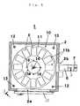
- FIG. 1is a plane sectional view of an incubator in an embodiment of the invention.
- FIG. 2is a plane sectional view of an incubator in other embodiment of the invention.
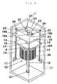
- FIG. 3is a side view of the incubator in the embodiment of the invention.
- FIG. 4is an internal see-through view of the incubator in the embodiment of the invention.
- FIG. 5is a block diagram showing a configuration of control system of the incubator in the embodiment of the invention.
- FIG. 6is a schematic process chart of a method of making the atmosphere uniform in a storage box of the incubator in the embodiment of the invention.
- FIG. 1Plane sectional views of incubator in embodiments of the invention are shown in FIG. 1 FIG. 2.
- a side sectional view of the incubatoris shown in FIG. 3 .
- the internal see-through view of the incubatoris given in FIG. 4 .
- the structure of the control system of the incubatoris shown in a block diagram in FIG. 5 .
- an incubator 1has a housing 2 of heat insulating walls.
- the housing 2incorporates a water jacket (not shown).
- Internal environmental conditions of the housing 2such as temperature, humidity, carbon dioxide concentration, and other gas concentration are controlled by an environment controller (not shown) so as to maintain specified conditions.
- a first opening 2 ais provided at the front side of the housing 2 .
- the first opening 2 ais opened and closed by a first door 3 .
- a second opening 2 bis provided at the side of the housing 2 .
- the second opening 2 bis large enough for passing at least one plate 6 which is a sample container, and is used as a plate access.
- a shutter 5which is a second door opening and closing in the vertical direction is provided in the second opening 2 b.
- the shutter 5is opened and closed automatically in the vertical direction by means of a cylinder 9 (see FIG. 5) used as a driving device.
- a door 33is opened, the first opening 2 a is opened, and the second opening 2 b is closed by the shutter 5 .
- a conveying device 7conveys the necessary container 6 to and from a dispensing device (not shown) through the second opening 2 b.
- Sample racks 10 coupling a plurality of layers of circular sample tables 11are disposed in the housing 2 .
- the sample table 11is an annular member having a circular hole 11 formed in the center.
- a plurality of platforms 11 b (twelve platforms in this embodiment) for mounting plates 6are disposed radially on the principal plane of the sample tables 11 .
- the plates 6are put on the platforms 11 b.
- Each platform 11 bis identified with an individual number.
- a specific platform 11 bis identified by this number by man or controller.
- FIG. 3is a sectional view along line 3 — 3 — 3 in FIG. 1 .
- the inside of the housing 2is divided into a first space 2 e and a second space 2 f by means of a horizontal partition wall 19 .
- the first space 2 e below the partition wall 19functions as a storage box for accommodating samples for biochemical process in a controlled environment.
- the second space 2 f above the partition wall 19is a power house incorporating a driving mechanism.
- the driving mechanismhas a function of driving the sample racks 10 disposed in the first space 2 e.
- the second space 2 fis closed, or an open space free from ceiling and four side walls.
- the sample racks 10couple the plurality of sample tables 11 vertically by means of coupling members.
- the sample table 11 of the highest layeris coupled to a rotating element 17 rotatably supported on an elevating member 18 through the coupling member 16 .
- a spline shaft 15 disposed verticallyis slidably inserted into the rotating element 17 .
- the lower end of the spline shaft 15is supported by a bearing 21 disposed at the bottom of the housing 2 .
- the upper part of the spline shaft 15is supported on a bearing 19 a provided in the shaft hole formed in the partition wall 19 , and projects into the second space 2 f.
- a pulley 24is coupled to the upper end of the spline shaft 15 .
- a pulley 22is coupled to an R-axis motor 20 disposed on the top of the partition wall 19 .
- a belt 23is stretched between the pulley 22 and the pulley 24 .
- the spline shaft 15rotates.
- the sample racks 10make rotary motions together with the spline shaft 15 . Therefore, the R-axis motor 20 , pulley 22 , belt 23 and pulley 24 rotate the sample racks 10 by rotating the spline shaft 15 , thereby composing a rotary drive mechanism.
- Two nuts 14are coupled to two diagonal positions of the elevating member 18 .
- a feed screw 13is driven into the two nuts 14 in the vertical direction.
- the feed screw 13is supported on the bearing 19 b fitted in the shaft hole formed in the partition wall 19 , and projects into the second space 2 f.
- a pulley 28is coupled to the upper end of the feed screw 13 .
- a pulley 27is coupled to a Z-axis motor 25 disposed on the partition wall 19 .
- a belt 29is stretched between the pulley 27 and the pulley 28 .
- Sliders 12 a(only one shown in FIG. 4) slidably engaged with two slide guides 12 (see FIG. 1) are mounted on the elevating member 18 .
- the elevating motion of the elevating member 18is guided by the slide guides 12 and sliders 12 a.
- the feed screw 13rotates and the elevating member 18 moves up and down. Therefore, the Z-axis motor 25 , pulley 27 , pulley 28 and belt 29 function as an elevating drive mechanism for rotating the feed screw 13 .
- the spline shaft 15 and feed screw 13are respectively coupled to the rotary drive mechanism and elevating drive mechanism through the bearings 19 a, 19 b provided in the partition wall 19 .
- the drive mechanismcan be disposed in the second space 2 f. That is, the second space 2 f is isolated from the first space 2 e generally in the atmosphere of high temperature and high humidity, and the drive mechanism such as motors installed in the second space 2 f is isolated and protected from the environments of high temperature and high humidity.
- the sample racks 10Along with the elevating motion of the elevating member 18 , the sample racks 10 also ascend and descend. At this time, the sample racks 10 can be rotated by the spline shaft 15 at any position in the vertical direction, so that the sample racks 10 move in combination of rotary motion and elevating motion.
- the rotary drive mechanism and elevating drive mechanismcompose a moving mechanism for moving the sample racks 10 . In this moving operation, by counting the pulse signals generated from the encoders built in the R-axis motor 20 and Z-axis motor 25 , the present position of each platform 11 b is identified.
- a cylinder drive unit 40drives the cylinder 9 .
- the cylinder 9moves the shutter 5 up and down.
- the shutter 5opens and closes the plate access 4 .
- a motor drive unit 41drives the R-axis motor 20 and Z-axis motor 25 .
- the R-axis motor 20rotates the sample racks 10 .
- the Z-axis motor 25elevates the elevating member 18 .
- An encoder 20 ais built in the R-axis motor 20 .
- This encoder 20 aissues pulse signals by detecting the rotation of the rotary shaft of the R-axis motor 20 .
- the pulse signalsare counted by an R-axis counter 20 b.
- An encoder 25 ais built in the Z-axis motor 25 .
- This encoder 25 aissues pulse signals by detecting the rotation of the rotary shaft of the Z-axis motor 25 .
- the pulse signalsare counted by a Z-axis counter 25 b.
- the counts by the R-axis counter 20 b and Z-axis counter 25 bare referred to as the information for identifying the position of the platform 11 b.
- the R-axis encoder 20 a, R-axis counter 20 b, Z-axis encoder 25 a and Z-axis counter 25 bfunction as the position detecting device for detecting the position of the sample rack.
- the position detecting deviceaside from the encoders built in the motors, a position detecting device for detecting directly the position of the sample rack 10 , and a detector for detecting the motion of the sample rack 10 and issuing a pulse signal may be also used.
- An environment controller 42holds the internal environmental conditions in the housing 2 , such as temperature, humidity and carbon dioxide concentration.
- a first communication unit 43exchanges signals necessary for control of parts of the incubator 1 .
- a controller 50is disposed in a dispensing device, not shown, used in combination with the incubator 1 .
- the first communication unit 43 of the incubator 1exchanges signals through a second communication unit 53 of the dispensing device.
- the controller 50controls the operation of the parts of the incubator 1 through the first communication unit 43 .
- the controller 50commands door opening and closing operation to the cylinder drive unit 40 .
- the controller 50refers to the counts of the R-axis counter 20 b and Z-axis counter 25 b, and identifies the position of the platform 11 b (for example, the number of the platform positioned before the second opening 2 b ).
- the controller 50further commands positioning of the sample racks 10 or agitation to the motor drive unit 41 .
- an arbitrary platform 11 bcan be positioned at a specific position, or the sample racks 10 are agitated by combination of elevating motion and rotary motion.
- the specific positionis, for example, a position capable of picking up a plate 6 on the platform 11 b through the second opening 2 b by means of the conveying device 7 .
- This agitating motionhas the function of positioning and agitating the internal atmosphere of the first space 2 e. As the sample racks 10 move at least by elevating or rotating, the internal atmosphere of the first space 2 e which is the environmental control chamber of the incubator 1 is agitated, and the temperature and humidity are made uniform.
- the controller 50functions as a control device for controlling the moving device for moving the sample racks 10 .
- the method for making uniform the atmosphere in the storage box of the incubatorroughly comprises:
- the incubatorPrior to start of biochemical process, the plates 6 are set in the incubator 1 . In this setting process, the plates 6 holding specified samples are put on specified platforms 11 b on sample tables 11 . At this time, the door 33 is opened, and the first opening 2 a is released. As a result, a wide opening range is assured, so that multiple plates can be put on specified positions efficiently. Also at the time of cleaning or maintenance of the inside of the housing 2 , a favorable working efficiency is assured.
- the door 33is shut, and the environment controller 42 is put in action.
- the inside of the housing 2is kept in specified environmental conditions.
- the biochemical treatmentis processed.
- the plates 6 finishing the specified culture timeare taken out from the incubator 1 by the conveying device 7 .
- Analysis, dispensing and other operationsare executed in the dispensing device.
- the plates 6are put back into the incubator 1 by the conveying device 7 . Such operation is repeated.
- the plates 6are put in and out through the second opening 2 b provided in the side wall partitioning between the incubator 1 and the outside. That is, the plates 6 are put in and out by the positioning operation for moving the sample racks for positioning the platform 11 b mounting the plates 6 to be discharged or an empty platform 11 b for mounting the incoming plates ahead of the second opening 2 b, the opening operation for opening and closing the shutter 5 for closing the second opening 11 b, and the moving operation for loading and unloading the plates 6 through the second opening 11 b by means of the conveying device 7 .
- the second opening 2 bhas a small opening size only for passing the plates 6 , and moreover only when necessary to put in and out the plates 6 , the shutter 5 for closing the second opening 2 b is opened automatically by the command from the controller 50 . It hence minimizes the disturbance of environmental conditions due to internal environmental atmosphere flowing out or fresh air flowing into the incubator 1 .
- the second opening 2 bis formed at the side of the housing 2 , but not limited to this, for example, the second opening may be also formed in the door 33 .
- the sample racks 10are moved at specific timing, and the atmosphere in the incubator is agitated.
- This agitating operationis a combination of rotary and elevating motions of the sample racks 10 .
- the atmosphere in the incubator including gaps in the sample tables 11can be uniformly agitated.
- the incubator 1 of the embodimentbrings about an excellent internal agitating effect as compared with the conventional incubators using draft fans or the like. Therefore, if numerous samples are contained at the same time, dispersion of treating conditions of samples does not occur.
- sample racks coupling circular sample tables moved by rotating and elevatingare not limited to this example, and, for example, sample racks having simple multi-rack structure or sample racks for mounting sample containers may be also used.
- moving means for making rotary and elevating motionscan be used, and, for example, a moving device using a quadrature coordinate robot or multi-articulated robot may be used.
- the incubator of the inventionmakes agitating operations to make uniform the atmosphere in the storage box by moving the sample racks. Accordingly, if the incubator has multiple layers of sample racks in complicated shape, the internal environmental condition in the incubator can be kept uniform, and the reliability of biochemical treatment is assured.
- the agitating operationis executed by using the drive device used for positioning of sample racks, and exclusive agitating device is not necessary. Therefore, the structure of the incubator is simplified, and the cost is reduced.
Landscapes
- Chemical & Material Sciences (AREA)
- Health & Medical Sciences (AREA)
- Life Sciences & Earth Sciences (AREA)
- Engineering & Computer Science (AREA)
- Organic Chemistry (AREA)
- Zoology (AREA)
- Wood Science & Technology (AREA)
- Bioinformatics & Cheminformatics (AREA)
- Biochemistry (AREA)
- General Health & Medical Sciences (AREA)
- Biomedical Technology (AREA)
- Analytical Chemistry (AREA)
- Physics & Mathematics (AREA)
- Biotechnology (AREA)
- Microbiology (AREA)
- Sustainable Development (AREA)
- Genetics & Genomics (AREA)
- General Engineering & Computer Science (AREA)
- General Physics & Mathematics (AREA)
- Immunology (AREA)
- Pathology (AREA)
- Chemical Kinetics & Catalysis (AREA)
- Thermal Sciences (AREA)
- Clinical Laboratory Science (AREA)
- Apparatus Associated With Microorganisms And Enzymes (AREA)
- Automatic Analysis And Handling Materials Therefor (AREA)
Abstract
Description
Claims (9)
Applications Claiming Priority (2)
| Application Number | Priority Date | Filing Date | Title |
|---|---|---|---|
| JP11-176461 | 1999-06-23 | ||
| JP17646199AJP3799876B2 (en) | 1999-06-23 | 1999-06-23 | incubator |
Publications (1)
| Publication Number | Publication Date |
|---|---|
| US6475776B1true US6475776B1 (en) | 2002-11-05 |
Family
ID=16014110
Family Applications (1)
| Application Number | Title | Priority Date | Filing Date |
|---|---|---|---|
| US09/595,585Expired - LifetimeUS6475776B1 (en) | 1999-06-23 | 2000-06-15 | Incubator, and method for making atmosphere uniform in incubator storage box |
Country Status (2)
| Country | Link |
|---|---|
| US (1) | US6475776B1 (en) |
| JP (1) | JP3799876B2 (en) |
Cited By (29)
| Publication number | Priority date | Publication date | Assignee | Title |
|---|---|---|---|---|
| US20030031602A1 (en)* | 2001-07-18 | 2003-02-13 | Irm, Llc | High throughput incubation devices |
| US20030215367A1 (en)* | 2002-04-19 | 2003-11-20 | Randox Laboratories Limited | Assay device incubator |
| US20040115101A1 (en)* | 2001-01-26 | 2004-06-17 | Malin Cosmas A | Air-conditioned storage cupboard |
| US20040135815A1 (en)* | 2002-12-16 | 2004-07-15 | Canon Kabushiki Kaisha | Method and apparatus for image metadata entry |
| EP1443101A1 (en)* | 2002-12-18 | 2004-08-04 | Liconic Ag | Incubator with moveable support |
| US20040213651A1 (en)* | 2003-01-10 | 2004-10-28 | Liconic Ag | Automatic storage device and climate controlled cabinet with such a device |
| US20060093514A1 (en)* | 2004-11-02 | 2006-05-04 | Dawes Dennis K | Platelet incubator |
| US20060289371A1 (en)* | 2005-05-09 | 2006-12-28 | Liconic Ag | Storage device for laboratory samples having storage racks and a shaker |
| US20080231152A1 (en)* | 2007-03-20 | 2008-09-25 | Liconic Ag | Automated substance storage |
| US20090305131A1 (en)* | 2008-04-25 | 2009-12-10 | Sujeet Kumar | High energy lithium ion batteries with particular negative electrode compositions |
| EP2148204A1 (en)* | 2008-07-25 | 2010-01-27 | F.Hoffmann-La Roche Ag | A laboratory storage and retrieval system and a method to handle laboratory sample tubes |
| US20110202170A1 (en)* | 2010-02-09 | 2011-08-18 | Dawes Dennis K | Access and inventory control for climate controlled storage |
| WO2012066101A1 (en)* | 2010-11-17 | 2012-05-24 | Andreas Hettich Gmbh & Co. Kg | Air-conditioning space for storing samples in a time-controlled manner and method for storing samples in a time-controlled manner |
| US20130334148A1 (en)* | 2010-11-17 | 2013-12-19 | Andreas Hettich Gmbh & Co. Kg | Incubator storage system |
| US20140117824A1 (en)* | 2011-06-14 | 2014-05-01 | Makoto Hayami | Constant-temperature device provided with rotating specimen table |
| WO2014122307A3 (en)* | 2013-02-11 | 2014-11-27 | Ge Healthcare Uk Limited | Cell culturing and/or biomanufacturing system |
| EP3106225A1 (en)* | 2015-06-15 | 2016-12-21 | Deutsches Zentrum für Luft- und Raumfahrt e.V. | Device and method for the thermal storage of samples |
| US9579245B2 (en) | 2013-07-26 | 2017-02-28 | Helmer, Inc. | Medical products storage device including access control |
| WO2017032829A1 (en) | 2015-08-25 | 2017-03-02 | General Electric Company | Improvements in and relating to biomanufacturing apparatus |
| CN109275657A (en)* | 2018-09-17 | 2019-01-29 | 上海原能细胞生物低温设备有限公司 | A spiral lift type cryogenic storage device |
| CN109413999A (en)* | 2016-07-08 | 2019-03-01 | S·哈梅尔巴彻 | Carousel Isolator |
| CN113588973A (en)* | 2021-07-31 | 2021-11-02 | 广州耐确医疗器械有限责任公司 | Full-automatic tissue sample sequencer |
| US20230046736A1 (en)* | 2021-08-10 | 2023-02-16 | Animal Care Systems, Inc. | Animal caging system for remote monitoring |
| CN117129822A (en)* | 2023-06-26 | 2023-11-28 | 盛吉盛智能装备(江苏)有限公司 | Temperature homogenization module and memory chip testing and sorting machine |
| US11959060B1 (en) | 2019-05-17 | 2024-04-16 | Humacyte, Inc. | Fluid systems, apparatuses, devices and methods of management thereof for cultivating tissue |
| US12104148B1 (en) | 2019-05-17 | 2024-10-01 | Humacyte, Inc. | System, apparatuses, devices and methods for straining a cultivated tissue |
| US12195711B1 (en)* | 2019-05-17 | 2025-01-14 | Humacyte, Inc. | Drawer system for cultivating tissue |
| WO2025126048A1 (en)* | 2023-12-11 | 2025-06-19 | Molecular Devices (Austria) GmbH | Systems and methods for stacking microplates |
| US12349789B2 (en) | 2017-10-17 | 2025-07-08 | Helmer Scientific, Llc | Undercounter refrigerator with access control |
Families Citing this family (6)
| Publication number | Priority date | Publication date | Assignee | Title |
|---|---|---|---|---|
| DE19936572B4 (en)* | 1999-08-03 | 2005-05-19 | Carl Zeiss Jena Gmbh | climate chamber |
| JP4660081B2 (en)* | 2003-09-29 | 2011-03-30 | 三洋電機株式会社 | Storage device |
| JP4983192B2 (en)* | 2006-10-04 | 2012-07-25 | 横河電機株式会社 | Incubator |
| CN108273689B (en)* | 2018-04-27 | 2019-01-18 | 盐城华夏高空建筑防腐维修有限公司 | A kind of agitating device of security mailbox anticorrosive paint |
| JP7058897B1 (en) | 2021-11-08 | 2022-04-25 | 株式会社総合水研究所 | Sample inspection equipment |
| KR20240061159A (en)* | 2022-10-31 | 2024-05-08 | 한국에너지기술연구원 | Automatic XRD Analysis System and Control Method Thereof |
Citations (4)
| Publication number | Priority date | Publication date | Assignee | Title |
|---|---|---|---|---|
| EP0339824A1 (en)* | 1988-04-29 | 1989-11-02 | Barnstead Thermolyne Corporation | Incubator |
| US5470744A (en)* | 1994-04-14 | 1995-11-28 | Astle; Thomas W. | Bioassay incubator for use with robotic arms |
| JPH11313666A (en)* | 1998-05-08 | 1999-11-16 | Matsushita Electric Ind Co Ltd | incubator |
| US6228636B1 (en)* | 1998-09-21 | 2001-05-08 | Matsushita Electric Industrial Co., Ltd. | Incubator |
- 1999
- 1999-06-23JPJP17646199Apatent/JP3799876B2/ennot_activeExpired - Fee Related
- 2000
- 2000-06-15USUS09/595,585patent/US6475776B1/ennot_activeExpired - Lifetime
Patent Citations (4)
| Publication number | Priority date | Publication date | Assignee | Title |
|---|---|---|---|---|
| EP0339824A1 (en)* | 1988-04-29 | 1989-11-02 | Barnstead Thermolyne Corporation | Incubator |
| US5470744A (en)* | 1994-04-14 | 1995-11-28 | Astle; Thomas W. | Bioassay incubator for use with robotic arms |
| JPH11313666A (en)* | 1998-05-08 | 1999-11-16 | Matsushita Electric Ind Co Ltd | incubator |
| US6228636B1 (en)* | 1998-09-21 | 2001-05-08 | Matsushita Electric Industrial Co., Ltd. | Incubator |
Cited By (59)
| Publication number | Priority date | Publication date | Assignee | Title |
|---|---|---|---|---|
| US20040115101A1 (en)* | 2001-01-26 | 2004-06-17 | Malin Cosmas A | Air-conditioned storage cupboard |
| US7544329B2 (en) | 2001-01-26 | 2009-06-09 | Liconic Ag | Air-conditioned storage cupboard |
| US20030031602A1 (en)* | 2001-07-18 | 2003-02-13 | Irm, Llc | High throughput incubation devices |
| US7329394B2 (en)* | 2001-07-18 | 2008-02-12 | Irm Llc | High throughput incubation devices |
| US20030215367A1 (en)* | 2002-04-19 | 2003-11-20 | Randox Laboratories Limited | Assay device incubator |
| US6881572B2 (en)* | 2002-04-19 | 2005-04-19 | Randox Laboratories Limited | Assay device incubator |
| US20040135815A1 (en)* | 2002-12-16 | 2004-07-15 | Canon Kabushiki Kaisha | Method and apparatus for image metadata entry |
| EP1443101A1 (en)* | 2002-12-18 | 2004-08-04 | Liconic Ag | Incubator with moveable support |
| US8192133B2 (en) | 2002-12-18 | 2012-06-05 | Liconic Ag | Climate controlled cabinet with movable carrier |
| US20050069401A1 (en)* | 2002-12-18 | 2005-03-31 | Liconic Ag | Climate controlled cabinet with movable carrier |
| US20090245986A1 (en)* | 2002-12-18 | 2009-10-01 | Liconic Ag | Climate controlled cabinet with movable carrier |
| US7510362B2 (en) | 2002-12-18 | 2009-03-31 | Liconic Ag | Climate controlled cabinet with movable carrier |
| US20040213651A1 (en)* | 2003-01-10 | 2004-10-28 | Liconic Ag | Automatic storage device and climate controlled cabinet with such a device |
| US7314341B2 (en) | 2003-01-10 | 2008-01-01 | Liconic Ag | Automatic storage device and climate controlled cabinet with such a device |
| US20060093514A1 (en)* | 2004-11-02 | 2006-05-04 | Dawes Dennis K | Platelet incubator |
| US7638100B2 (en)* | 2004-11-02 | 2009-12-29 | Helmer, Inc. | Platelet incubator |
| US20060289371A1 (en)* | 2005-05-09 | 2006-12-28 | Liconic Ag | Storage device for laboratory samples having storage racks and a shaker |
| US7832921B2 (en) | 2005-05-09 | 2010-11-16 | Liconic Ag | Storage device for laboratory samples having storage racks and a shaker |
| US8152360B2 (en) | 2005-05-09 | 2012-04-10 | Liconic Ag | Storage device for laboratory samples having storage racks and a shaker |
| US20110085409A1 (en)* | 2005-05-09 | 2011-04-14 | Liconic Ag | Storage device for laboratory samples having storage racks and a shaker |
| US20080231152A1 (en)* | 2007-03-20 | 2008-09-25 | Liconic Ag | Automated substance storage |
| US8857208B2 (en) | 2007-03-20 | 2014-10-14 | Liconic Ag | Automated substance storage |
| US20090305131A1 (en)* | 2008-04-25 | 2009-12-10 | Sujeet Kumar | High energy lithium ion batteries with particular negative electrode compositions |
| US20100028124A1 (en)* | 2008-07-25 | 2010-02-04 | Joachim Lackner | Laboratory storage and retrieval system and a method to handle laboratory sample tubes |
| US8100266B2 (en)* | 2008-07-25 | 2012-01-24 | Roche Diagnostics Operations, Inc. | Laboratory storage and retrieval system and a method to handle laboratory sample tubes |
| EP2148204A1 (en)* | 2008-07-25 | 2010-01-27 | F.Hoffmann-La Roche Ag | A laboratory storage and retrieval system and a method to handle laboratory sample tubes |
| US20110202170A1 (en)* | 2010-02-09 | 2011-08-18 | Dawes Dennis K | Access and inventory control for climate controlled storage |
| US20140030802A1 (en)* | 2010-11-17 | 2014-01-30 | Andreas Hettich Gmbh & Co. Kg | Conditioning chamber for storing samples in a time-controlled manner and method for storing samples in a time-controlled manner |
| EP2641095B1 (en)* | 2010-11-17 | 2018-01-10 | Andreas Hettich GmbH&Co. KG | Air-conditioning space for storing samples in a time-controlled manner and method for storing samples in a time-controlled manner |
| WO2012066101A1 (en)* | 2010-11-17 | 2012-05-24 | Andreas Hettich Gmbh & Co. Kg | Air-conditioning space for storing samples in a time-controlled manner and method for storing samples in a time-controlled manner |
| AU2011331101B2 (en)* | 2010-11-17 | 2015-06-18 | Andreas Hettich Gmbh & Co. Kg | Air-conditioning space for storing samples in a time-controlled manner and method for storing samples in a time-controlled manner |
| US20130334148A1 (en)* | 2010-11-17 | 2013-12-19 | Andreas Hettich Gmbh & Co. Kg | Incubator storage system |
| US9562214B2 (en)* | 2010-11-17 | 2017-02-07 | Andreas Hettich Gmbh & Co. Kg | Conditioning chamber for storing samples in a time-controlled manner and method for storing samples in a time-controlled manner |
| US20140117824A1 (en)* | 2011-06-14 | 2014-05-01 | Makoto Hayami | Constant-temperature device provided with rotating specimen table |
| US9364082B2 (en)* | 2011-06-14 | 2016-06-14 | Rorze Corporation | Constant-temperature device provided with rotating specimen table |
| WO2014122307A3 (en)* | 2013-02-11 | 2014-11-27 | Ge Healthcare Uk Limited | Cell culturing and/or biomanufacturing system |
| AU2014213897B2 (en)* | 2013-02-11 | 2018-05-10 | Global Life Sciences Solutions Operations UK Ltd | Cell culturing and/or biomanufacturing system |
| US9926525B2 (en) | 2013-02-11 | 2018-03-27 | Ge Healthcare Uk Limited | Cell culturing and/or biomanufacturing system |
| US11883335B2 (en) | 2013-07-26 | 2024-01-30 | Helmer Scientific, Llc | Medical products storage device including access control |
| US9579245B2 (en) | 2013-07-26 | 2017-02-28 | Helmer, Inc. | Medical products storage device including access control |
| US10821044B2 (en) | 2013-07-26 | 2020-11-03 | Helmer, Inc. | Medical products storage device including access control |
| US11534356B2 (en) | 2013-07-26 | 2022-12-27 | Helmer, Inc. | Medical products storage device including access control |
| US12251342B2 (en) | 2013-07-26 | 2025-03-18 | Helmer Scientific, Llc | Medical products storage device including access control |
| EP3106225A1 (en)* | 2015-06-15 | 2016-12-21 | Deutsches Zentrum für Luft- und Raumfahrt e.V. | Device and method for the thermal storage of samples |
| WO2017032829A1 (en) | 2015-08-25 | 2017-03-02 | General Electric Company | Improvements in and relating to biomanufacturing apparatus |
| CN109413999A (en)* | 2016-07-08 | 2019-03-01 | S·哈梅尔巴彻 | Carousel Isolator |
| US12349789B2 (en) | 2017-10-17 | 2025-07-08 | Helmer Scientific, Llc | Undercounter refrigerator with access control |
| US11946684B2 (en) | 2018-09-17 | 2024-04-02 | Shanghai Origincell Biological Cryo Equipment Co., Ltd. | Spirally ascending/descending cryogenic storage apparatus |
| CN109275657A (en)* | 2018-09-17 | 2019-01-29 | 上海原能细胞生物低温设备有限公司 | A spiral lift type cryogenic storage device |
| CN109275657B (en)* | 2018-09-17 | 2023-07-04 | 上海原能细胞生物低温设备有限公司 | A spiral lift type cryogenic storage device |
| US12195711B1 (en)* | 2019-05-17 | 2025-01-14 | Humacyte, Inc. | Drawer system for cultivating tissue |
| US11959060B1 (en) | 2019-05-17 | 2024-04-16 | Humacyte, Inc. | Fluid systems, apparatuses, devices and methods of management thereof for cultivating tissue |
| US12104148B1 (en) | 2019-05-17 | 2024-10-01 | Humacyte, Inc. | System, apparatuses, devices and methods for straining a cultivated tissue |
| CN113588973A (en)* | 2021-07-31 | 2021-11-02 | 广州耐确医疗器械有限责任公司 | Full-automatic tissue sample sequencer |
| US20230046736A1 (en)* | 2021-08-10 | 2023-02-16 | Animal Care Systems, Inc. | Animal caging system for remote monitoring |
| US12356959B2 (en)* | 2021-08-10 | 2025-07-15 | Animal Care Systems, Inc. | Animal caging system for remote monitoring |
| CN117129822B (en)* | 2023-06-26 | 2024-04-16 | 盛吉盛智能装备(江苏)有限公司 | Temperature homogenizing module and memory chip test sorting machine |
| CN117129822A (en)* | 2023-06-26 | 2023-11-28 | 盛吉盛智能装备(江苏)有限公司 | Temperature homogenization module and memory chip testing and sorting machine |
| WO2025126048A1 (en)* | 2023-12-11 | 2025-06-19 | Molecular Devices (Austria) GmbH | Systems and methods for stacking microplates |
Also Published As
| Publication number | Publication date |
|---|---|
| JP3799876B2 (en) | 2006-07-19 |
| JP2001000171A (en) | 2001-01-09 |
Similar Documents
| Publication | Publication Date | Title |
|---|---|---|
| US6475776B1 (en) | Incubator, and method for making atmosphere uniform in incubator storage box | |
| US6228636B1 (en) | Incubator | |
| US7141413B2 (en) | Incubator | |
| EP1313990B1 (en) | Automated storage and retrieval apparatus for freezers and related method thereof | |
| US4632808A (en) | Chemical manipulator | |
| KR101232675B1 (en) | Constant-temperature equipment | |
| US20060177922A1 (en) | Environmental control incubator with removable drawer and robot | |
| US6536859B1 (en) | Climatic cabinet | |
| US20110124093A1 (en) | Constant-temperature equipment | |
| US7785867B2 (en) | Culture device and storage container | |
| JP2000093156A (en) | incubator | |
| JP2009284810A (en) | Incubator | |
| EP1757883A2 (en) | Automated storage and retrieval apparatus for freezers and related method thereof | |
| JP3758423B2 (en) | incubator | |
| JPH1189559A (en) | incubator | |
| JP4597244B2 (en) | incubator | |
| JP3799956B2 (en) | incubator | |
| JP2002202315A (en) | Dispensing device with incubator | |
| EP3637109B1 (en) | Analyzer and analyzer control method | |
| JP3545324B2 (en) | Culture device | |
| JP3783401B2 (en) | incubator | |
| JP6854616B2 (en) | Sample container transport device and cell culture system | |
| JP2006296296A (en) | Warehouse for storing and holding article | |
| JP2004166558A (en) | Incubator | |
| JP2006034256A (en) | Storing apparatus |
Legal Events
| Date | Code | Title | Description |
|---|---|---|---|
| AS | Assignment | Owner name:MATSUSHITA ELECTRIC INDUSTRIAL CO., LTD., JAPAN Free format text:ASSIGNMENT OF ASSIGNORS INTEREST;ASSIGNOR:HIGUCHI, AKIRA;REEL/FRAME:011292/0116 Effective date:20001019 | |
| STCF | Information on status: patent grant | Free format text:PATENTED CASE | |
| FEPP | Fee payment procedure | Free format text:PAYOR NUMBER ASSIGNED (ORIGINAL EVENT CODE: ASPN); ENTITY STATUS OF PATENT OWNER: LARGE ENTITY | |
| FPAY | Fee payment | Year of fee payment:4 | |
| AS | Assignment | Owner name:PANASONIC CORPORATION, JAPAN Free format text:CHANGE OF NAME;ASSIGNOR:MATSUSHITA ELECTRIC INDUSTRIAL CO., LTD.;REEL/FRAME:023241/0594 Effective date:20081001 | |
| AS | Assignment | Owner name:WAKO PURE CHEMICAL INDUSTRIES, LTD., JAPAN Free format text:ASSIGNMENT OF ASSIGNORS INTEREST;ASSIGNOR:PANASONIC CORPORATION;REEL/FRAME:023312/0692 Effective date:20090924 | |
| FPAY | Fee payment | Year of fee payment:8 | |
| FPAY | Fee payment | Year of fee payment:12 | |
| AS | Assignment | Owner name:FUJIFILM WAKO PURE CHEMICAL CORPORATION, JAPAN Free format text:CHANGE OF NAME;ASSIGNOR:WAKO PURE CHEMICAL INDUSTRIES, LTD.;REEL/FRAME:046086/0396 Effective date:20180402 |