US6475336B1 - Electrostatically clamped edge ring for plasma processing - Google Patents
Electrostatically clamped edge ring for plasma processingDownload PDFInfo
- Publication number
- US6475336B1 US6475336B1US09/680,515US68051500AUS6475336B1US 6475336 B1US6475336 B1US 6475336B1US 68051500 AUS68051500 AUS 68051500AUS 6475336 B1US6475336 B1US 6475336B1
- Authority
- US
- United States
- Prior art keywords
- edge ring
- chuck
- substrate
- edge
- plasma
- Prior art date
- Legal status (The legal status is an assumption and is not a legal conclusion. Google has not performed a legal analysis and makes no representation as to the accuracy of the status listed.)
- Expired - Lifetime, expires
Links
Images


Classifications
- H—ELECTRICITY
- H01—ELECTRIC ELEMENTS
- H01L—SEMICONDUCTOR DEVICES NOT COVERED BY CLASS H10
- H01L21/00—Processes or apparatus adapted for the manufacture or treatment of semiconductor or solid state devices or of parts thereof
- H01L21/02—Manufacture or treatment of semiconductor devices or of parts thereof
- H01L21/04—Manufacture or treatment of semiconductor devices or of parts thereof the devices having potential barriers, e.g. a PN junction, depletion layer or carrier concentration layer
- H01L21/18—Manufacture or treatment of semiconductor devices or of parts thereof the devices having potential barriers, e.g. a PN junction, depletion layer or carrier concentration layer the devices having semiconductor bodies comprising elements of Group IV of the Periodic Table or AIIIBV compounds with or without impurities, e.g. doping materials
- H01L21/30—Treatment of semiconductor bodies using processes or apparatus not provided for in groups H01L21/20 - H01L21/26
- H01L21/302—Treatment of semiconductor bodies using processes or apparatus not provided for in groups H01L21/20 - H01L21/26 to change their surface-physical characteristics or shape, e.g. etching, polishing, cutting
- H01L21/306—Chemical or electrical treatment, e.g. electrolytic etching
- H01L21/3065—Plasma etching; Reactive-ion etching
- H—ELECTRICITY
- H01—ELECTRIC ELEMENTS
- H01L—SEMICONDUCTOR DEVICES NOT COVERED BY CLASS H10
- H01L21/00—Processes or apparatus adapted for the manufacture or treatment of semiconductor or solid state devices or of parts thereof
- H01L21/67—Apparatus specially adapted for handling semiconductor or electric solid state devices during manufacture or treatment thereof; Apparatus specially adapted for handling wafers during manufacture or treatment of semiconductor or electric solid state devices or components ; Apparatus not specifically provided for elsewhere
- H01L21/67005—Apparatus not specifically provided for elsewhere
- H01L21/67011—Apparatus for manufacture or treatment
- H01L21/67098—Apparatus for thermal treatment
- H01L21/67109—Apparatus for thermal treatment mainly by convection
- C—CHEMISTRY; METALLURGY
- C23—COATING METALLIC MATERIAL; COATING MATERIAL WITH METALLIC MATERIAL; CHEMICAL SURFACE TREATMENT; DIFFUSION TREATMENT OF METALLIC MATERIAL; COATING BY VACUUM EVAPORATION, BY SPUTTERING, BY ION IMPLANTATION OR BY CHEMICAL VAPOUR DEPOSITION, IN GENERAL; INHIBITING CORROSION OF METALLIC MATERIAL OR INCRUSTATION IN GENERAL
- C23C—COATING METALLIC MATERIAL; COATING MATERIAL WITH METALLIC MATERIAL; SURFACE TREATMENT OF METALLIC MATERIAL BY DIFFUSION INTO THE SURFACE, BY CHEMICAL CONVERSION OR SUBSTITUTION; COATING BY VACUUM EVAPORATION, BY SPUTTERING, BY ION IMPLANTATION OR BY CHEMICAL VAPOUR DEPOSITION, IN GENERAL
- C23C16/00—Chemical coating by decomposition of gaseous compounds, without leaving reaction products of surface material in the coating, i.e. chemical vapour deposition [CVD] processes
- C23C16/44—Chemical coating by decomposition of gaseous compounds, without leaving reaction products of surface material in the coating, i.e. chemical vapour deposition [CVD] processes characterised by the method of coating
- C23C16/458—Chemical coating by decomposition of gaseous compounds, without leaving reaction products of surface material in the coating, i.e. chemical vapour deposition [CVD] processes characterised by the method of coating characterised by the method used for supporting substrates in the reaction chamber
- C23C16/4582—Rigid and flat substrates, e.g. plates or discs
- C23C16/4583—Rigid and flat substrates, e.g. plates or discs the substrate being supported substantially horizontally
- C23C16/4585—Devices at or outside the perimeter of the substrate support, e.g. clamping rings, shrouds
- C—CHEMISTRY; METALLURGY
- C23—COATING METALLIC MATERIAL; COATING MATERIAL WITH METALLIC MATERIAL; CHEMICAL SURFACE TREATMENT; DIFFUSION TREATMENT OF METALLIC MATERIAL; COATING BY VACUUM EVAPORATION, BY SPUTTERING, BY ION IMPLANTATION OR BY CHEMICAL VAPOUR DEPOSITION, IN GENERAL; INHIBITING CORROSION OF METALLIC MATERIAL OR INCRUSTATION IN GENERAL
- C23C—COATING METALLIC MATERIAL; COATING MATERIAL WITH METALLIC MATERIAL; SURFACE TREATMENT OF METALLIC MATERIAL BY DIFFUSION INTO THE SURFACE, BY CHEMICAL CONVERSION OR SUBSTITUTION; COATING BY VACUUM EVAPORATION, BY SPUTTERING, BY ION IMPLANTATION OR BY CHEMICAL VAPOUR DEPOSITION, IN GENERAL
- C23C16/00—Chemical coating by decomposition of gaseous compounds, without leaving reaction products of surface material in the coating, i.e. chemical vapour deposition [CVD] processes
- C23C16/44—Chemical coating by decomposition of gaseous compounds, without leaving reaction products of surface material in the coating, i.e. chemical vapour deposition [CVD] processes characterised by the method of coating
- C23C16/458—Chemical coating by decomposition of gaseous compounds, without leaving reaction products of surface material in the coating, i.e. chemical vapour deposition [CVD] processes characterised by the method of coating characterised by the method used for supporting substrates in the reaction chamber
- C23C16/4582—Rigid and flat substrates, e.g. plates or discs
- C23C16/4583—Rigid and flat substrates, e.g. plates or discs the substrate being supported substantially horizontally
- C23C16/4586—Elements in the interior of the support, e.g. electrodes, heating or cooling devices
- H—ELECTRICITY
- H01—ELECTRIC ELEMENTS
- H01L—SEMICONDUCTOR DEVICES NOT COVERED BY CLASS H10
- H01L21/00—Processes or apparatus adapted for the manufacture or treatment of semiconductor or solid state devices or of parts thereof
- H01L21/67—Apparatus specially adapted for handling semiconductor or electric solid state devices during manufacture or treatment thereof; Apparatus specially adapted for handling wafers during manufacture or treatment of semiconductor or electric solid state devices or components ; Apparatus not specifically provided for elsewhere
- H01L21/683—Apparatus specially adapted for handling semiconductor or electric solid state devices during manufacture or treatment thereof; Apparatus specially adapted for handling wafers during manufacture or treatment of semiconductor or electric solid state devices or components ; Apparatus not specifically provided for elsewhere for supporting or gripping
- H01L21/6831—Apparatus specially adapted for handling semiconductor or electric solid state devices during manufacture or treatment thereof; Apparatus specially adapted for handling wafers during manufacture or treatment of semiconductor or electric solid state devices or components ; Apparatus not specifically provided for elsewhere for supporting or gripping using electrostatic chucks
- H—ELECTRICITY
- H01—ELECTRIC ELEMENTS
- H01J—ELECTRIC DISCHARGE TUBES OR DISCHARGE LAMPS
- H01J2237/00—Discharge tubes exposing object to beam, e.g. for analysis treatment, etching, imaging
- H01J2237/32—Processing objects by plasma generation
- Y—GENERAL TAGGING OF NEW TECHNOLOGICAL DEVELOPMENTS; GENERAL TAGGING OF CROSS-SECTIONAL TECHNOLOGIES SPANNING OVER SEVERAL SECTIONS OF THE IPC; TECHNICAL SUBJECTS COVERED BY FORMER USPC CROSS-REFERENCE ART COLLECTIONS [XRACs] AND DIGESTS
- Y10—TECHNICAL SUBJECTS COVERED BY FORMER USPC
- Y10T—TECHNICAL SUBJECTS COVERED BY FORMER US CLASSIFICATION
- Y10T279/00—Chucks or sockets
- Y10T279/23—Chucks or sockets with magnetic or electrostatic means
Definitions
- the present inventionrelates to an improved apparatus and method for plasma processing and, in particular, an improved apparatus and method for plasma etching semiconductor substrates.
- vacuum processing chambersare generally used for etching and chemical vapor deposition (CVD) of materials on substrates by supplying an etching or deposition gas to the vacuum chamber and application of an RF field to the gas to energize the gas into a plasma state.
- CVDchemical vapor deposition
- TCPTMtransformer coupled plasma
- ICPinductively coupled plasma
- ECRelectron-cyclotron resonance
- the substratesare typically held in place within the vacuum chamber on substrate holders by mechanical clamps and electrostatic clamps (ESC).
- ESCelectrostatic clamps
- Examples of such clamping systems and components thereofcan be found in commonly owned U.S. Pat. Nos. 5,262,029 and 5,838,529.
- An example of a monopolar chuckcan be found in U.S. Pat. No. 4,665,463 and examples of bipolar chucks can be found in U.S. Pat. Nos. 4,692,836 and 5,055,964.
- cooling gassuch as helium can be supplied to the backside of the substrate. Examples of such cooling can be found in U.S. Pat. Nos. 5,160,152; 5,238,499; and 5,350,479.
- Substrate supportscan include consumable (sacrificial) edge rings around the substrate for purposes of confining plasma to the area above the wafer and/or protect the ESC from erosion by the plasma.
- an edge ring arrangementis described in commonly owned U.S. Pat. Nos. 5,805,408; 5,998,932; 6,013,984; and 6,039,836.
- Other examples of edge ring arrangementscan be found in U.S. Pat. Nos. 5,494,523; 5,986,874; 6,022,809; 6,096,161; and 6,117,349.
- the present inventionprovides an edge ring clamping assembly adapted to surround a substrate support in a plasma reaction chamber.
- the edge ring clamping assemblyincludes a member having an annular support surface and an electrostatic edge ring chuck on the support surface.
- the edge ring chuckcomprises an outer portion of a ceramic body mounted on the substrate support and the ceramic body includes an electrostatic wafer chuck located radially inward of the edge ring chuck.
- an axially extending grooveis located in the annular support surface and the groove is adapted to receive a mating projection of an edge ring clamped on the edge ring chuck.
- At least one gas passageextends through the member and the edge ring chuck such that a heat transfer gas can be supplied to an exposed surface of the edge ring chuck.
- the edge ring chuckcan comprise a bipolar chuck and/or an edge ring of electrically conductive material can be clamped to the member by the edge ring chuck.
- the present inventionalso provides a plasma reaction chamber comprising a substrate support on which a wafer to be processed can be mounted and an electrostatic edge ring chuck on which an edge ring can be supported during processing.
- the substrate supportcomprises a temperature controlled electrode adapted to maintain the edge ring below a threshold temperature by heat conduction from the edge ring to the substrate support.
- the edge ringincludes a recess on an inside edge of an upper surface thereof and the recess is adapted to fit beneath a wafer mounted on the substrate support with a clearance gap between the edge ring and the wafer of no more than about 0.003 inch.
- the substrate supportcan comprise an RF driven electrode and/or the plasma reaction chamber can comprise a parallel plate reactor such as an etch chamber having an upper electrode facing the baseplate.
- the present inventionalso provides a method of treating a semiconductor substrate such as a wafer in a plasma chamber wherein the plasma chamber comprises a substrate support, an electrostatic wafer chuck on an upper surface of the substrate support and an electrostatic edge ring chuck on which an edge ring can be supported.
- the methodcomprises the steps of electrostatically clamping a wafer to the wafer chuck, electrostatically clamping an edge ring to the edge ring chuck, supplying a process gas to the interior of the plasma chamber, energizing the process gas into a plasma state, and processing the wafer with the plasma.
- a heat transfer gascan be supplied to an interface between the edge ring and the edge ring clamp to maintain the temperature of the edge ring below a threshold temperature.
- FIG. 1is a partial view of a parallel plate plasma processing apparatus according to the present invention
- FIG. 2is a partial view of a plasma chamber comprising an edge ring chuck mounted on a coupling ring according to one embodiment of the present invention
- FIG. 3is a partial view of a plasma chamber comprising an edge ring chuck mounted on a baseplate according to another embodiment of the present invention
- FIG. 4is a partial view of a plasma chamber according to the invention comprising an integral edge ring/wafer chuck mounted on a baseplate;
- FIG. 5is a partial view of a plasma chamber according to another embodiment of the invention comprising an edge ring adapted to fit into a groove in the baseplate between the wafer and edge ring chucks.
- the inventionprovides an improved substrate support arrangement for a plasma reactor wherein a sacrificial edge ring surrounds a semiconductor substrate such as a silicon wafer.
- a sacrificial edge ringsurrounds a semiconductor substrate such as a silicon wafer.
- the ringcan become very hot during plasma processing of the substrate.
- the thermal expansion of the edge ring during plasma processingmakes it necessary to provide sufficient clearance between the edge ring and the substrate so that the hot edge ring does not lift the substrate off of the substrate support.
- thermal coupling from the edge ring to the substrate supportis improved with the result that plasma erosion of the edge ring can be reduced and/or the clearance gap between the edge ring and the wafer can be reduced to thereby minimize erosion of the wafer chuck by plasma penetrating the gap between the edge ring and the wafer chuck.
- the edge ring assembly according to the present inventioncan be designed in a manner which achieves more uniform plasma processing of semiconductor substrates.
- the improved uniformitycan be achieved by providing an RF impedance path which is similar at the center and edge of a substrate undergoing plasma processing.
- the RF impedance pathcan be manipulated by choice of materials for the wafer chuck and edge ring chuck according to the present invention.
- an RF biascan be applied to a substrate undergoing plasma processing by a powered electrode underlying the wafer chuck.
- the RF impedance path from the powered electrode through the wafer chuck and substrate to the plasmacan be different than the RF impedance path from an outer portion of the powered electrode to the plasma, a nonuniform plasma density which results at the edge of the substrate can lead to nonuniform processing of the substrate.
- the inventionovercomes this using materials for the edge ring chuck and edge ring which provide a more uniform RF impedance path at the center and edge of the substrate so as to provide more uniformity of the plasma density across the substrate.
- the inventioncan be implemented in various plasma reactors such as parallel plate, inductively coupled, ECR, helicon, or other type of plasma reaction chamber.
- plasma reactorssuch as parallel plate, inductively coupled, ECR, helicon, or other type of plasma reaction chamber.
- the inventionis described in the following with reference to a parallel plate type plasma reaction chamber especially suited for plasma etching.
- the inventionis also applicable to other chamber designs and/or plasma processing operations other than etching.
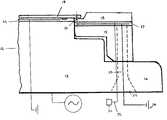
- FIG. 1shows a parallel plate plasma reaction chamber 10 according to one embodiment the invention.
- the apparatuscomprises an upper electrode 11 and a lower electrode assembly 12 .
- the lower electrode assemblycomprises a baseplate 13 and an electrostatic wafer chuck 14 located on an upper surface thereof.
- a coupling ring 15rests on a flange 16 of the baseplate.
- the coupling ring 15has an edge ring chuck 17 located on an upper surface thereof.
- An edge ring 18is supported on the exposed upper surface of the edge ring chuck 17 .
- a wafer 19is mounted on the wafer chuck 14 such as to overlap the wafer chuck and the inner surface of the edge ring 18 .
- the wafer 19overlaps the edge of the wafer chuck so that the exposure of the edge of the wafer chuck 14 to the ions/reactive species in the plasma is reduced. Otherwise, exposure of the wafer chuck 14 to the plasma can cause erosion of the wafer chuck and necessitate replacement of the entire substrate support assembly or at least the wafer chuck portion thereof thus causing production delay and expense associated with the repair.
- the edge ring 18is intended to be a consumable or replaceable part which protects the wafer chuck from plasma erosion.
- the wafer 19overhangs the wafer chuck 14 and a portion of the edge ring 18 extends under the edge of the wafer 19 , e.g., the wafer 19 can overhang the edge of the wafer chuck 14 by 1 to 2 mm.
- the top of the edge ring 18is positioned as closely as possible to the underside of the wafer 19 , thermal expansion of the edge ring during processing of a wafer makes it necessary to provide a clearance gap between the underside of the wafer and the edge ring large enough to allow for the thermal expansion of the edge ring and avoid the expanded edge ring from lifting the wafer off of the wafer chuck during the process.
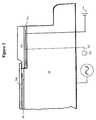
- FIG. 2is an enlarged view of the lower electrode assembly 12 of FIG. 1 .
- the wafer 19is shown overlapping the edge ring 18 to form a gap or clearance 23 between the wafer backside and the edge ring 18 .
- the inner edge of the edge ring 18contacts or is located close to the outer edge of the wafer chuck 14 so as to maintain the edge ring 18 in a desired position with respect to the wafer 19 .
- the edge ring chuck 17can extend completely across the coupling ring 15 or the edge ring chuck 17 can be located in a recess in the upper surface of the coupling ring 15 .
- the coupling ring 15can be supported on the base plate 13 with or without mechanical or adhesive fastening such as a plurality of bolts 24 .
- the edge ring chuck 17which can be a monopolar or bipolar chuck, can be supplied with DC power by a suitable power supply arrangement such as a DC power supply 26 using an electrical connection, e.g., lead line 28 extending through a passage in one of the bolts 24 .
- a heat transfer gassuch as He or process gas from a gas source 30 can be supplied via gas passage 32 to the interface between the coupling ring 15 and the base plate 13 and/or between the edge ring chuck 17 and the edge ring 18 .
- the gas passage 32can extend through the base plate 13 and coupling ring 15 at one or more locations spaced around the base plate 13 , e.g., extending through passages in the bolts 28 .
- FIGS. 3-5show variations of how the edge ring chuck can be mounted on the base plate rather than on a coupling ring.
- an edge ring chuck 34is supported on an outer portion of the baseplate 32 and a wafer chuck 36 is supported on a central portion of the baseplate 32 such that the upper surface of the chuck 36 is vertically higher than the upper surface of the chuck 34 .
- a gas supply 30can supply a heat transfer gas through one or more gas passages 32 into an interface between the edge ring chuck 34 and the edge ring 30 .
- one or more depressionscan be provided in the lower surface of the edge ring and/or the opposed upper surface of the edge ring chuck 34 to enhance the cooling of the edge ring.
- the RF impedance from the baseplate 32 through the chuck 36 and wafer 38 to the plasma above the wafercan be made similar to the RF impedance path from the baseplate 32 through the chuck 34 and edge ring 30 .
- the edge ring chuck and wafer chuckcomprises an integral part 40 mounted on the substrate support. As shown, a peripheral portion of the part 40 is recessed relative to a central portion of the part 40 such that an edge ring 44 fits in the recess and a wafer 42 overlies an inner portion of the edge ring 44 . As in the previous embodiments, the edge ring includes an inner flange which fits beneath the outer edge of the wafer.
- the edge ring chuck and the wafer chuckcould comprise a single monopolar or bipolar electrode, it is preferable for the edge ring to be operated separately from the wafer chuck.
- the edge ring chuckcan be supplied power by a DC power supply 46 and the wafer chuck can be supplied power by another power supply (not shown).
- FIG. 5shows an arrangement wherein the edge ring includes a portion which fits within a groove in the substrate support.
- an edge ring chuck 50 and a wafer chuck 52are mounted directly on a baseplate 54 such that the upper surfaces of the edge ring and wafer chucks 50 , 52 are approximately coplanar.
- An axially extending groove 56is provided in the baseplate 54 at a location which separates the edge ring and wafer chucks 50 , 52 .
- the edge ring 58includes a mating projection 60 configured to fit in the groove 56 in the baseplate 54 and a radially extending portion 62 of the edge ring 58 overlies the edge ring chuck 50 .
- the projection 60is preferable sized to allow for thermal expansion of the edge ring 58 during plasma processing of a wafer 66 .
- the axially and radially extending portions 60 , 62 of the edge ring 58are connected by a transition portion 64 which is configured to allow the wafer 66 to overlap an inner surface of the edge ring 58 .
- the underside of the edge ring 58can be supplied with a heat transfer gas 68 .
- the interfaces between the axially extending portion 60 of the edge ring 58 and the groove 56 in the baseplate 54can also be provided with heat transfer gas to further improve thermal coupling of the baseplate and edge ring 58 .
- the edge ring chuck 50 and wafer chuck 52of similar materials, the RF impedance path can be made more similar from the center to edge of the wafer.
- controlling the temperature of the edge ringcan reduce the amount of thermal expansion of the edge ring during processing of a wafer and thereby allow for smaller clearances between the top of the edge ring and the underside of the wafer.
- the clearance between the backside of the wafer and the edge ringcan be reduced by 50% or more, e.g., the clearance can be reduced from 0.005-0.006 inch to 0.002-0.003 inch.
- the reduced clearancewhich can be realized according to the invention provides more protection to the wafer chuck, i.e., more plasma is prevented from entering the clearance gap and attacking the wafer chuck with the smaller clearance gap. Further, the tendency of particles generated during plasma processing to build up on the edge of the wafer chuck can be reduced. As is known, particle build-up can prevent the wafer from uniformly contacting the wafer chuck resulting in diminished clamping capacity and/or particle contamination of the wafer. Another advantage is that by lowering the temperature of the edge ring during processing it may be possible to reduce the rate of erosion of the edge ring, i.e., reducing the temperature of the edge ring can reduce the chemical reaction rates of the edge ring material with the ions/chemical species in the plasma.
- the edge ring arrangement according to the inventioncan improve plasma etch performance. For example, improvements in etch uniformity can result from better thermal management at the wafer edge and/or improvement in RF impedance path matching.
- temperature at the wafer edgeif the wafer and edge ring are maintained at similar temperatures during processing, the etch characteristics can be made more uniform from center to edge of the wafer.
- RF impedance path matchingusing an edge ring chuck made of the same materials as the wafer chuck minimizes disruption to the RF impedance path from the bottom electrode to the plasma from center to edge of the wafer.
- This effectcan be further improved by selecting a material for the edge ring which is similar in characteristics to the wafer undergoing processing, e.g., if a silicon wafer is being processed the edge ring can be comprised entirely of silicon so that the RF impedance path from the bottom electrode through the edge ring can be made more similar to the impedance path from the bottom electrode through the wafer.
- the current density in the plasma region adjacent the wafer and edge ring surfacescan be made more uniform and thereby improve etch uniformity.
- the edge ringcan be made from any suitable material with electrically conductive material such as silicon and silicon carbide being preferred. Because the edge ring is exposed directly to the plasma, it is desirable to use highly pure materials such as single crystal silicon, polycrystalline silicon, CVD silicon carbide, or the like. Other materials can include quartz, aluminum oxide, aluminum nitride, silicon nitride, etc. In order to achieve clamping of the edge ring it may be advantageous in the case of nonconductive materials to include an electrically conductive insert in the edge ring as disclosed in commonly owned U.S. Pat. No. 6,039,836, the disclosure of which is hereby incorporated by reference.
- the edge ring chuck and the wafer chuckcan be made from any suitable materials such as those used in conventional electrostatic wafer chucks including anodized aluminum, polyimides and ceramic materials.
- the edge ring chuck (and optionally the wafer chuck)can be made from a ceramic material such as alumina or aluminum nitride with the electrode or electrodes being made from any suitable conductive material.
- the electrodesare preferably made from a refractory metal such as tungsten or molybdenum which can withstand the high temperatures encountered during sintering of the chuck, e.g., the edge ring chuck can be made by a sintering process such as sandwiching a refractory metal electrode (tungsten ink) between two ceramic green sheets and firing to form the sintered structure.
- the edge ring chuckcan be of the coulombic (fully insulating) or Johnsen-Rahbeck type (semi-conducting).
- the edge ring chuckmay be secured to the coupling ring or substrate support using any of the methods and materials known in the art for securing wafer chucks.
- the edge ring chuckfor example, may be secured using a high temperature polymer adhesive such as a silicone adhesive.
Landscapes
- Chemical & Material Sciences (AREA)
- Engineering & Computer Science (AREA)
- Physics & Mathematics (AREA)
- Condensed Matter Physics & Semiconductors (AREA)
- General Physics & Mathematics (AREA)
- Manufacturing & Machinery (AREA)
- Computer Hardware Design (AREA)
- Microelectronics & Electronic Packaging (AREA)
- Power Engineering (AREA)
- General Chemical & Material Sciences (AREA)
- Chemical Kinetics & Catalysis (AREA)
- Materials Engineering (AREA)
- Mechanical Engineering (AREA)
- Metallurgy (AREA)
- Organic Chemistry (AREA)
- Plasma & Fusion (AREA)
- Drying Of Semiconductors (AREA)
- Container, Conveyance, Adherence, Positioning, Of Wafer (AREA)
- Application Of Or Painting With Fluid Materials (AREA)
- Chemical Vapour Deposition (AREA)
- Physical Or Chemical Processes And Apparatus (AREA)
- Treatments Of Macromolecular Shaped Articles (AREA)
Abstract
Description
The present invention relates to an improved apparatus and method for plasma processing and, in particular, an improved apparatus and method for plasma etching semiconductor substrates.
In the field of semiconductor processing, vacuum processing chambers are generally used for etching and chemical vapor deposition (CVD) of materials on substrates by supplying an etching or deposition gas to the vacuum chamber and application of an RF field to the gas to energize the gas into a plasma state. Examples of parallel plate, transformer coupled plasma (TCP™) which is also called inductively coupled plasma (ICP), and electron-cyclotron resonance (ECR) reactors and components thereof are disclosed in commonly owned U.S. Pat. Nos. 4,340,462; 4,948,458; 5,200,232 and 5,820,723. U.S. Pat. No. 4,793,975 also discloses a parallel plate plasma reactor.
During processing of semiconductor substrates, the substrates are typically held in place within the vacuum chamber on substrate holders by mechanical clamps and electrostatic clamps (ESC). Examples of such clamping systems and components thereof can be found in commonly owned U.S. Pat. Nos. 5,262,029 and 5,838,529. An example of a monopolar chuck can be found in U.S. Pat. No. 4,665,463 and examples of bipolar chucks can be found in U.S. Pat. Nos. 4,692,836 and 5,055,964. In order to cool the substrates, cooling gas such as helium can be supplied to the backside of the substrate. Examples of such cooling can be found in U.S. Pat. Nos. 5,160,152; 5,238,499; and 5,350,479.
Substrate supports can include consumable (sacrificial) edge rings around the substrate for purposes of confining plasma to the area above the wafer and/or protect the ESC from erosion by the plasma. For instance, an edge ring arrangement is described in commonly owned U.S. Pat. Nos. 5,805,408; 5,998,932; 6,013,984; and 6,039,836. Other examples of edge ring arrangements can be found in U.S. Pat. Nos. 5,494,523; 5,986,874; 6,022,809; 6,096,161; and 6,117,349.
In plasma processing arrangements wherein a sacrificial ring surrounds a wafer, it would be desirable to improve the thermal contact between the ring and an underlying portion of the substrate support. By improving thermal coupling, improved temperature control of the ring could be realized and the clearances required between the ring and the wafer could be reduced. It would also be desirable if the RF impedance path from the baseplate to the plasma in the area above the wafer could be more closely matched to the RF impedance path from the baseplate to the plasma in the area of the edge ring in order to improve plasma uniformity near the edge of the wafer.
The present invention provides an edge ring clamping assembly adapted to surround a substrate support in a plasma reaction chamber. The edge ring clamping assembly includes a member having an annular support surface and an electrostatic edge ring chuck on the support surface. According to one embodiment, the edge ring chuck comprises an outer portion of a ceramic body mounted on the substrate support and the ceramic body includes an electrostatic wafer chuck located radially inward of the edge ring chuck. According to another embodiment, an axially extending groove is located in the annular support surface and the groove is adapted to receive a mating projection of an edge ring clamped on the edge ring chuck. Optionally, at least one gas passage extends through the member and the edge ring chuck such that a heat transfer gas can be supplied to an exposed surface of the edge ring chuck. The edge ring chuck can comprise a bipolar chuck and/or an edge ring of electrically conductive material can be clamped to the member by the edge ring chuck.
The present invention also provides a plasma reaction chamber comprising a substrate support on which a wafer to be processed can be mounted and an electrostatic edge ring chuck on which an edge ring can be supported during processing. In one embodiment, the substrate support comprises a temperature controlled electrode adapted to maintain the edge ring below a threshold temperature by heat conduction from the edge ring to the substrate support. In another embodiment, the edge ring includes a recess on an inside edge of an upper surface thereof and the recess is adapted to fit beneath a wafer mounted on the substrate support with a clearance gap between the edge ring and the wafer of no more than about 0.003 inch. The substrate support can comprise an RF driven electrode and/or the plasma reaction chamber can comprise a parallel plate reactor such as an etch chamber having an upper electrode facing the baseplate.
The present invention also provides a method of treating a semiconductor substrate such as a wafer in a plasma chamber wherein the plasma chamber comprises a substrate support, an electrostatic wafer chuck on an upper surface of the substrate support and an electrostatic edge ring chuck on which an edge ring can be supported. In a preferred embodiment, the method comprises the steps of electrostatically clamping a wafer to the wafer chuck, electrostatically clamping an edge ring to the edge ring chuck, supplying a process gas to the interior of the plasma chamber, energizing the process gas into a plasma state, and processing the wafer with the plasma. During the process, a heat transfer gas can be supplied to an interface between the edge ring and the edge ring clamp to maintain the temperature of the edge ring below a threshold temperature.
FIG. 1 is a partial view of a parallel plate plasma processing apparatus according to the present invention;
FIG. 2 is a partial view of a plasma chamber comprising an edge ring chuck mounted on a coupling ring according to one embodiment of the present invention;
FIG. 3 is a partial view of a plasma chamber comprising an edge ring chuck mounted on a baseplate according to another embodiment of the present invention;
FIG. 4 is a partial view of a plasma chamber according to the invention comprising an integral edge ring/wafer chuck mounted on a baseplate; and
FIG. 5 is a partial view of a plasma chamber according to another embodiment of the invention comprising an edge ring adapted to fit into a groove in the baseplate between the wafer and edge ring chucks.
The invention provides an improved substrate support arrangement for a plasma reactor wherein a sacrificial edge ring surrounds a semiconductor substrate such as a silicon wafer. In arrangements wherein an edge ring merely rests on the underlying substrate support and is held in place by gravity and/or frictional engagement with the substrate support, the ring can become very hot during plasma processing of the substrate. In the case where the substrate overlies a portion of the edge ring, the thermal expansion of the edge ring during plasma processing makes it necessary to provide sufficient clearance between the edge ring and the substrate so that the hot edge ring does not lift the substrate off of the substrate support. According to the present invention, thermal coupling from the edge ring to the substrate support is improved with the result that plasma erosion of the edge ring can be reduced and/or the clearance gap between the edge ring and the wafer can be reduced to thereby minimize erosion of the wafer chuck by plasma penetrating the gap between the edge ring and the wafer chuck.
The edge ring assembly according to the present invention can be designed in a manner which achieves more uniform plasma processing of semiconductor substrates. The improved uniformity can be achieved by providing an RF impedance path which is similar at the center and edge of a substrate undergoing plasma processing. The RF impedance path can be manipulated by choice of materials for the wafer chuck and edge ring chuck according to the present invention. As is known, an RF bias can be applied to a substrate undergoing plasma processing by a powered electrode underlying the wafer chuck. However, because the RF impedance path from the powered electrode through the wafer chuck and substrate to the plasma can be different than the RF impedance path from an outer portion of the powered electrode to the plasma, a nonuniform plasma density which results at the edge of the substrate can lead to nonuniform processing of the substrate. The invention overcomes this using materials for the edge ring chuck and edge ring which provide a more uniform RF impedance path at the center and edge of the substrate so as to provide more uniformity of the plasma density across the substrate.
The invention can be implemented in various plasma reactors such as parallel plate, inductively coupled, ECR, helicon, or other type of plasma reaction chamber. For purposes of explanation, the invention is described in the following with reference to a parallel plate type plasma reaction chamber especially suited for plasma etching. However, the invention is also applicable to other chamber designs and/or plasma processing operations other than etching.
FIG. 1 shows a parallel plateplasma reaction chamber 10 according to one embodiment the invention. The apparatus comprises anupper electrode 11 and alower electrode assembly 12. The lower electrode assembly comprises abaseplate 13 and anelectrostatic wafer chuck 14 located on an upper surface thereof. Acoupling ring 15 rests on aflange 16 of the baseplate. Thecoupling ring 15 has anedge ring chuck 17 located on an upper surface thereof. Anedge ring 18 is supported on the exposed upper surface of theedge ring chuck 17. Awafer 19 is mounted on thewafer chuck 14 such as to overlap the wafer chuck and the inner surface of theedge ring 18.
Thewafer 19 overlaps the edge of the wafer chuck so that the exposure of the edge of thewafer chuck 14 to the ions/reactive species in the plasma is reduced. Otherwise, exposure of thewafer chuck 14 to the plasma can cause erosion of the wafer chuck and necessitate replacement of the entire substrate support assembly or at least the wafer chuck portion thereof thus causing production delay and expense associated with the repair. Theedge ring 18 is intended to be a consumable or replaceable part which protects the wafer chuck from plasma erosion. In order to further protect the wafer chuck, thewafer 19 overhangs thewafer chuck 14 and a portion of theedge ring 18 extends under the edge of thewafer 19, e.g., thewafer 19 can overhang the edge of thewafer chuck 14 by 1 to 2 mm. Further, while the top of theedge ring 18 is positioned as closely as possible to the underside of thewafer 19, thermal expansion of the edge ring during processing of a wafer makes it necessary to provide a clearance gap between the underside of the wafer and the edge ring large enough to allow for the thermal expansion of the edge ring and avoid the expanded edge ring from lifting the wafer off of the wafer chuck during the process.
FIG. 2 is an enlarged view of thelower electrode assembly 12 of FIG.1. Thewafer 19 is shown overlapping theedge ring 18 to form a gap orclearance 23 between the wafer backside and theedge ring 18. The inner edge of theedge ring 18 contacts or is located close to the outer edge of thewafer chuck 14 so as to maintain theedge ring 18 in a desired position with respect to thewafer 19. Theedge ring chuck 17 can extend completely across thecoupling ring 15 or theedge ring chuck 17 can be located in a recess in the upper surface of thecoupling ring 15. Thecoupling ring 15 can be supported on thebase plate 13 with or without mechanical or adhesive fastening such as a plurality ofbolts 24. Theedge ring chuck 17, which can be a monopolar or bipolar chuck, can be supplied with DC power by a suitable power supply arrangement such as aDC power supply 26 using an electrical connection, e.g.,lead line 28 extending through a passage in one of thebolts 24. In order to improve thermal transfer between theedge ring 18 and thebase plate 13, a heat transfer gas such as He or process gas from agas source 30 can be supplied viagas passage 32 to the interface between thecoupling ring 15 and thebase plate 13 and/or between theedge ring chuck 17 and theedge ring 18. Thegas passage 32 can extend through thebase plate 13 andcoupling ring 15 at one or more locations spaced around thebase plate 13, e.g., extending through passages in thebolts 28.
FIGS. 3-5 show variations of how the edge ring chuck can be mounted on the base plate rather than on a coupling ring. As shown in FIG. 3, anedge ring chuck 34 is supported on an outer portion of thebaseplate 32 and awafer chuck 36 is supported on a central portion of thebaseplate 32 such that the upper surface of thechuck 36 is vertically higher than the upper surface of thechuck 34. To promote heat transfer from thechuck 34 to thebaseplate 32, agas supply 30 can supply a heat transfer gas through one ormore gas passages 32 into an interface between theedge ring chuck 34 and theedge ring 30. If desired, one or more depressions (which can be filled with the heat transfer gas) can be provided in the lower surface of the edge ring and/or the opposed upper surface of theedge ring chuck 34 to enhance the cooling of the edge ring. Also, by using similar materials for the edge ring chuck and the wafer chuck, the RF impedance from thebaseplate 32 through thechuck 36 andwafer 38 to the plasma above the wafer can be made similar to the RF impedance path from thebaseplate 32 through thechuck 34 andedge ring 30.
In FIG. 4, the edge ring chuck and wafer chuck comprises anintegral part 40 mounted on the substrate support. As shown, a peripheral portion of thepart 40 is recessed relative to a central portion of thepart 40 such that anedge ring 44 fits in the recess and awafer 42 overlies an inner portion of theedge ring 44. As in the previous embodiments, the edge ring includes an inner flange which fits beneath the outer edge of the wafer. Although the edge ring chuck and the wafer chuck could comprise a single monopolar or bipolar electrode, it is preferable for the edge ring to be operated separately from the wafer chuck. Thus, the edge ring chuck can be supplied power by aDC power supply 46 and the wafer chuck can be supplied power by another power supply (not shown).
FIG. 5 shows an arrangement wherein the edge ring includes a portion which fits within a groove in the substrate support. As shown, anedge ring chuck 50 and awafer chuck 52 are mounted directly on abaseplate 54 such that the upper surfaces of the edge ring and wafer chucks50,52 are approximately coplanar. An axially extendinggroove 56 is provided in thebaseplate 54 at a location which separates the edge ring and wafer chucks50,52. Theedge ring 58 includes amating projection 60 configured to fit in thegroove 56 in thebaseplate 54 and aradially extending portion 62 of theedge ring 58 overlies theedge ring chuck 50. Theprojection 60 is preferable sized to allow for thermal expansion of theedge ring 58 during plasma processing of awafer 66. The axially and radially extendingportions edge ring 58 are connected by atransition portion 64 which is configured to allow thewafer 66 to overlap an inner surface of theedge ring 58. As with the other embodiments, the underside of theedge ring 58 can be supplied with a heat transfer gas68. The interfaces between theaxially extending portion 60 of theedge ring 58 and thegroove 56 in thebaseplate 54 can also be provided with heat transfer gas to further improve thermal coupling of the baseplate andedge ring 58. Further, by making theedge ring chuck 50 andwafer chuck 52 of similar materials, the RF impedance path can be made more similar from the center to edge of the wafer.
Better temperature control of the edge ring allows for process advantages. For example, controlling the temperature of the edge ring can reduce the amount of thermal expansion of the edge ring during processing of a wafer and thereby allow for smaller clearances between the top of the edge ring and the underside of the wafer. Compared to the case where the edge ring merely rests on the underlying coupling ring or substrate support, when using the edge ring chuck according to the invention the clearance between the backside of the wafer and the edge ring can be reduced by 50% or more, e.g., the clearance can be reduced from 0.005-0.006 inch to 0.002-0.003 inch. The reduced clearance which can be realized according to the invention provides more protection to the wafer chuck, i.e., more plasma is prevented from entering the clearance gap and attacking the wafer chuck with the smaller clearance gap. Further, the tendency of particles generated during plasma processing to build up on the edge of the wafer chuck can be reduced. As is known, particle build-up can prevent the wafer from uniformly contacting the wafer chuck resulting in diminished clamping capacity and/or particle contamination of the wafer. Another advantage is that by lowering the temperature of the edge ring during processing it may be possible to reduce the rate of erosion of the edge ring, i.e., reducing the temperature of the edge ring can reduce the chemical reaction rates of the edge ring material with the ions/chemical species in the plasma.
The edge ring arrangement according to the invention can improve plasma etch performance. For example, improvements in etch uniformity can result from better thermal management at the wafer edge and/or improvement in RF impedance path matching. With regard to temperature at the wafer edge, if the wafer and edge ring are maintained at similar temperatures during processing, the etch characteristics can be made more uniform from center to edge of the wafer. With regard to RF impedance path matching, using an edge ring chuck made of the same materials as the wafer chuck minimizes disruption to the RF impedance path from the bottom electrode to the plasma from center to edge of the wafer. This effect can be further improved by selecting a material for the edge ring which is similar in characteristics to the wafer undergoing processing, e.g., if a silicon wafer is being processed the edge ring can be comprised entirely of silicon so that the RF impedance path from the bottom electrode through the edge ring can be made more similar to the impedance path from the bottom electrode through the wafer. Thus, the current density in the plasma region adjacent the wafer and edge ring surfaces can be made more uniform and thereby improve etch uniformity.
The edge ring can be made from any suitable material with electrically conductive material such as silicon and silicon carbide being preferred. Because the edge ring is exposed directly to the plasma, it is desirable to use highly pure materials such as single crystal silicon, polycrystalline silicon, CVD silicon carbide, or the like. Other materials can include quartz, aluminum oxide, aluminum nitride, silicon nitride, etc. In order to achieve clamping of the edge ring it may be advantageous in the case of nonconductive materials to include an electrically conductive insert in the edge ring as disclosed in commonly owned U.S. Pat. No. 6,039,836, the disclosure of which is hereby incorporated by reference.
The edge ring chuck and the wafer chuck can be made from any suitable materials such as those used in conventional electrostatic wafer chucks including anodized aluminum, polyimides and ceramic materials. The edge ring chuck (and optionally the wafer chuck) can be made from a ceramic material such as alumina or aluminum nitride with the electrode or electrodes being made from any suitable conductive material. With sintered ceramic chucks, the electrodes are preferably made from a refractory metal such as tungsten or molybdenum which can withstand the high temperatures encountered during sintering of the chuck, e.g., the edge ring chuck can be made by a sintering process such as sandwiching a refractory metal electrode (tungsten ink) between two ceramic green sheets and firing to form the sintered structure. The edge ring chuck can be of the coulombic (fully insulating) or Johnsen-Rahbeck type (semi-conducting). The edge ring chuck may be secured to the coupling ring or substrate support using any of the methods and materials known in the art for securing wafer chucks. The edge ring chuck, for example, may be secured using a high temperature polymer adhesive such as a silicone adhesive.
Although the present invention has been described in connection with preferred embodiments thereof, it will be appreciated by those skilled in the art that additions, deletions, modifications, and substitutions not specifically described can be made without departing from the spirit and scope of the invention as defined in the appended claims.
Claims (23)
1. An edge ring clamping assembly adapted to surround a substrate support in a plasma reaction chamber, the edge ring clamping assembly comprising:
a member having an annular support surface;
an electrostatic edge ring chuck on the annular support surface; and
an edge ring on the edge ring chuck dimensioned so as to provide a clearance gap between a lower surface of a substrate located on the substrate support and an upper surface of the edge ring.
2. The edge ring clamping assembly ofclaim 1 , wherein the edge ring chuck comprises an outer portion of a ceramic body mounted on the substrate support, the ceramic body including an electrostatic substrate chuck located radially inward of the edge ring chuck.
3. The edge ring clamping assembly ofclaim 1 , wherein a groove is located in the annular support surface, the groove being adapted to receive a mating projection of the edge ring clamped on the edge ring chuck.
4. The edge ring clamping assembly ofclaim 1 , further comprising at least one gas passage extending through the member and the edge ring chuck, the gas passage being adapted to supply a heat transfer gas to an exposed surface of the edge ring chuck.
5. The edge ring clamping assembly ofclaim 1 , wherein the edge ring chuck comprises a bipolar chuck.
6. A plasma reaction chamber, comprising:
an edge ring clamping assembly adapted to surround a substrate support in the plasma reaction chamber, the edge ring clamping assembly comprising:
a member having an annular support surface;
an electrostatic edge ring chuck on the annular support surface; and
an edge ring on the edge ring chuck dimensioned so as to provide a clearance gap between a lower surface of a substrate located on the substrate support and an upper surface of the edge ring.
7. The plasma chamber ofclaim 6 , wherein the substrate support comprises a baseplate having an electrostatic substrate chuck on an upper surface thereof.
8. The plasma chamber ofclaim 7 , wherein an upper surface of the substrate chuck is higher in a vertical direction with respect to an upper ring chuck.
9. The plasma chamber ofclaim 7 , wherein the substrate support includes a groove between the electrostatic substrate chuck and the edge ring chuck, the groove being adapted to receive a mating projection of the edge ring clamped on the edge ring chuck.
10. The plasma chamber ofclaim 7 , wherein the baseplate comprises an RF driven electrode.
11. The plasma chamber ofclaim 10 , wherein the plasma reaction chamber comprises a parallel plate reactor having an upper electrode facing the baseplate.
12. The plasma chamber ofclaim 11 , further comprising a substrate mounted on the substrate chuck such that the outer edge of the substrate overhangs the edge ring with a clearance gap of less than about 0.003 inch between the lower surface of the substrate and an upper surface of the edge ring.
13. A method of treating a semiconductor substrate in the plasma chamber ofclaim 7 , said method comprising the steps of:
electrostatically clamping a substrate to the substrate chuck;
electrostatically clamping the edge ring to the edge ring chuck;
supplying a process gas to the interior of the plasma chamber;
energizing the process gas into a plasma state; and
processing the substrate with the plasma.
14. The method ofclaim 13 , further comprising controlling the temperature of the edge ring by supplying a heat transfer gas between opposed surfaces of the edge ring and the annular support.
15. The plasma chamber ofclaim 6 , wherein the edge ring chuck comprises an outer portion of a ceramic body mounted on the substrate support, the ceramic body including an electrostatic substrate chuck located radially inward of the edge ring chuck.
16. The plasma chamber ofclaim 6 , wherein the edge ring is adapted to be electrostatically clamped to the edge ring chuck.
17. The plasma chamber ofclaim 6 , wherein the edge ring is comprised entirely of an electrically conductive material selected from silicon and silicon carbide.
18. The plasma chamber ofclaim 6 , wherein the substrate support comprises a temperature controlled electrode adapted to maintain the edge ring below a threshold temperature by heat conduction from the edge ring to the substrate support.
19. The plasma chamber ofclaim 6 , wherein the substrate support includes an annular flange and a coupling ring mounted on the annular flange, the edge ring chuck being located on an upper surface of the coupling ring, the edge ring being clamped on the coupling ring such that a recess in an upper surface of the edge ring is located beneath an outer periphery of a substrate mounted on the substrate support.
20. The plasma chamber ofclaim 6 , wherein the plasma chamber is a semiconductor etching apparatus.
21. An edge ring clamping assembly adapted to surround a substrate support in a plasma reaction chamber, the edge ring clamping assembly comprising:
a member having an annular support surface;
an electrostatic edge ring chuck on the annular support surface;
and an edge ring on the edge ring chuck, the edge ring being comprised entirely of an electrically conductive material and dimensioned so as to provide a clearance gap between a lower surface of a substrate located on the substrate support and an upper surface of the edge ring.
22. The edge ring clamping assembly ofclaim 21 , wherein the edge ring consists essentially of an electrically conductive material selected from the group consisting of silicon, silicon carbide, single crystal silicon, polycrystalline silicon, and CVD silicon carbide.
23. An edge ring clamping assembly adapted to surround a substrate support in a plasma reaction chamber, the edge ring clamping assembly comprising:
a member having an annular support surface; and
an electrostatic edge ring chuck on the annular support surface, wherein the substrate support includes an annular flange and a coupling ring mounted on the annular flange, the edge ring chuck being located on an upper surface of the coupling ring, the edge ring being clamped on the edge ring chuck such that a recess in an upper surface of the edge ring is located beneath an outer periphery of a substrate mounted on the substrate support, the edge ring chuck and the edge ring being effective to provide a more uniform RF impedance path at the center and edge of the substrate.
Priority Applications (13)
| Application Number | Priority Date | Filing Date | Title |
|---|---|---|---|
| US09/680,515US6475336B1 (en) | 2000-10-06 | 2000-10-06 | Electrostatically clamped edge ring for plasma processing |
| DE60135672TDE60135672D1 (en) | 2000-10-06 | 2001-09-26 | ELECTROSTATIC FIXED RIM RING FOR PLASMA PROCESSING |
| PCT/US2001/030286WO2002031219A1 (en) | 2000-10-06 | 2001-09-26 | Electrostatically clamped edge ring for plasma processing |
| EP01977216AEP1332241B1 (en) | 2000-10-06 | 2001-09-26 | Electrostatically clamped edge ring for plasma processing |
| CA002419130ACA2419130A1 (en) | 2000-10-06 | 2001-09-26 | Electrostatically clamped edge ring for plasma processing |
| CNB018167756ACN1285757C (en) | 2000-10-06 | 2001-09-26 | Electrostatically clamped edge rings for plasma machining |
| IL15443901AIL154439A0 (en) | 2000-10-06 | 2001-09-26 | Electrostatically clamped edge ring for plasma processing |
| JP2002534582AJP4913313B2 (en) | 2000-10-06 | 2001-09-26 | Edge ring clamping assembly, plasma reaction chamber, and method of processing a semiconductor substrate |
| AU2001296352AAU2001296352A1 (en) | 2000-10-06 | 2001-09-26 | Electrostatically clamped edge ring for plasma processing |
| KR1020037003501AKR100807136B1 (en) | 2000-10-06 | 2001-09-26 | A method of processing a semiconductor substrate using a plasma chamber and a coupling ring assembly comprising an electrostatic edge ring chuck useful in a plasma chamber. |
| CNB2006101592011ACN100424849C (en) | 2000-10-06 | 2001-09-26 | Electrostatically clamped edge rings for plasma machining |
| AT01977216TATE407232T1 (en) | 2000-10-06 | 2001-09-26 | ELECTROSTATIC CLAMPED EDGE RING FOR PLASMA PROCESSING |
| IL154439AIL154439A (en) | 2000-10-06 | 2003-02-13 | Electrostatically clamped edge ring for plasma processing |
Applications Claiming Priority (1)
| Application Number | Priority Date | Filing Date | Title |
|---|---|---|---|
| US09/680,515US6475336B1 (en) | 2000-10-06 | 2000-10-06 | Electrostatically clamped edge ring for plasma processing |
Publications (1)
| Publication Number | Publication Date |
|---|---|
| US6475336B1true US6475336B1 (en) | 2002-11-05 |
Family
ID=24731424
Family Applications (1)
| Application Number | Title | Priority Date | Filing Date |
|---|---|---|---|
| US09/680,515Expired - LifetimeUS6475336B1 (en) | 2000-10-06 | 2000-10-06 | Electrostatically clamped edge ring for plasma processing |
Country Status (11)
| Country | Link |
|---|---|
| US (1) | US6475336B1 (en) |
| EP (1) | EP1332241B1 (en) |
| JP (1) | JP4913313B2 (en) |
| KR (1) | KR100807136B1 (en) |
| CN (2) | CN100424849C (en) |
| AT (1) | ATE407232T1 (en) |
| AU (1) | AU2001296352A1 (en) |
| CA (1) | CA2419130A1 (en) |
| DE (1) | DE60135672D1 (en) |
| IL (2) | IL154439A0 (en) |
| WO (1) | WO2002031219A1 (en) |
Cited By (111)
| Publication number | Priority date | Publication date | Assignee | Title |
|---|---|---|---|---|
| US20030106646A1 (en)* | 2001-12-11 | 2003-06-12 | Applied Materials, Inc. | Plasma chamber insert ring |
| US20040053428A1 (en)* | 2002-09-18 | 2004-03-18 | Steger Robert J. | Method and apparatus for the compensation of edge ring wear in a plasma processing chamber |
| US20040074605A1 (en)* | 2001-02-15 | 2004-04-22 | Takaaki Nezu | Focus ring for semiconductor treatment and plasma treatment device |
| US20040129226A1 (en)* | 2002-12-20 | 2004-07-08 | Tokyo Electron Limited | Method and apparatus for an improved focus ring in a plasma processing system |
| US20040134618A1 (en)* | 2003-01-07 | 2004-07-15 | Tokyo Electron Limited | Plasma processing apparatus and focus ring |
| US20040177927A1 (en)* | 2001-07-10 | 2004-09-16 | Akihiro Kikuchi | Plasma procesor and plasma processing method |
| US20050103274A1 (en)* | 2003-11-14 | 2005-05-19 | Cheng-Tsung Yu | Reliability assessment system and method |
| US20050133164A1 (en)* | 2003-12-17 | 2005-06-23 | Andreas Fischer | Temperature controlled hot edge ring assembly for reducing plasma reactor etch rate drift |
| US20050193951A1 (en)* | 2004-03-08 | 2005-09-08 | Muneo Furuse | Plasma processing apparatus |
| US20050230049A1 (en)* | 2004-04-14 | 2005-10-20 | Ryoji Nishio | Method and apparatus for plasma processing |
| US20050279457A1 (en)* | 2004-06-04 | 2005-12-22 | Tokyo Electron Limited | Plasma processing apparatus and method, and plasma control unit |
| US20060090706A1 (en)* | 2004-11-03 | 2006-05-04 | Applied Materials, Inc. | Support ring assembly |
| US20070032081A1 (en)* | 2005-08-08 | 2007-02-08 | Jeremy Chang | Edge ring assembly with dielectric spacer ring |
| US20070131350A1 (en)* | 2005-07-19 | 2007-06-14 | Anthony Ricci | Method of protecting a bond layer in a substrate support adapted for use in a plasma processing system |
| US20080020574A1 (en)* | 2006-07-18 | 2008-01-24 | Lam Research Corporation | Hybrid RF capacitively and inductively coupled plasma source using multifrequency RF powers and methods of use thereof |
| US20080066868A1 (en)* | 2006-09-19 | 2008-03-20 | Tokyo Electron Limited | Focus ring and plasma processing apparatus |
| US20080173401A1 (en)* | 2005-08-04 | 2008-07-24 | Jusung Engineering Co., Ltd. | Plasma etching apparatus |
| US20080187430A1 (en)* | 2007-02-01 | 2008-08-07 | Amitava Datta | Semiconductor process chamber |
| US20080194113A1 (en)* | 2006-09-20 | 2008-08-14 | Samsung Electronics Co., Ltd. | Methods and apparatus for semiconductor etching including an electro static chuck |
| US20080236749A1 (en)* | 2007-03-28 | 2008-10-02 | Tokyo Electron Limited | Plasma processing apparatus |
| US20080289766A1 (en)* | 2007-05-22 | 2008-11-27 | Samsung Austin Semiconductor Lp | Hot edge ring apparatus and method for increased etch rate uniformity and reduced polymer buildup |
| US20090025636A1 (en)* | 2007-07-27 | 2009-01-29 | Applied Materials, Inc. | High profile minimum contact process kit for hdp-cvd application |
| US20090075687A1 (en)* | 2005-05-15 | 2009-03-19 | Sony Computer Entertainment Inc. | Center Device |
| US20090090695A1 (en)* | 2004-08-26 | 2009-04-09 | Lam Research Corporation | Yttria insulator ring for use inside a plasma chamber |
| US20090089971A1 (en)* | 2007-09-25 | 2009-04-09 | Vanderlinden Roger P | Sealed pick-up head for a mobile sweeper |
| US20090163034A1 (en)* | 2007-12-19 | 2009-06-25 | Lam Research Corporation | Composite showerhead electrode assembly for a plasma processing apparatus |
| US7581511B2 (en) | 2003-10-10 | 2009-09-01 | Micron Technology, Inc. | Apparatus and methods for manufacturing microfeatures on workpieces using plasma vapor processes |
| US7588804B2 (en) | 2002-08-15 | 2009-09-15 | Micron Technology, Inc. | Reactors with isolated gas connectors and methods for depositing materials onto micro-device workpieces |
| US20090261065A1 (en)* | 2008-04-18 | 2009-10-22 | Lam Research Corporation | Components for use in a plasma chamber having reduced particle generation and method of making |
| US20100040768A1 (en)* | 2008-08-15 | 2010-02-18 | Lam Research Corporation | Temperature controlled hot edge ring assembly |
| US20100044974A1 (en)* | 2008-08-19 | 2010-02-25 | Lam Research Corporation | Edge rings for electrostatic chucks |
| US20100078899A1 (en)* | 2008-09-26 | 2010-04-01 | Lam Research Corporation | Adjustable thermal contact between an electrostatic chuck and a hot edge ring by clocking a coupling ring |
| US20100089323A1 (en)* | 2002-09-20 | 2010-04-15 | Tokyo Electron Limited | Method for coating internal member having holes in vacuum processing apparatus and the internal member having holes coated by using the coating method |
| US7699932B2 (en) | 2004-06-02 | 2010-04-20 | Micron Technology, Inc. | Reactors, systems and methods for depositing thin films onto microfeature workpieces |
| US20100116436A1 (en)* | 2008-11-07 | 2010-05-13 | Tokyo Electron Limited | Ring-shaped member and method for manufacturing same |
| US20100159703A1 (en)* | 2008-12-19 | 2010-06-24 | Andreas Fischer | Methods and apparatus for dual confinement and ultra-high pressure in an adjustable gap plasma chamber |
| US7762114B2 (en) | 2005-09-09 | 2010-07-27 | Applied Materials, Inc. | Flow-formed chamber component having a textured surface |
| GB2419895B (en)* | 2004-11-04 | 2010-09-22 | Trikon Technologies Ltd | Shielding design for backside metal deposition |
| US20100304571A1 (en)* | 2007-12-19 | 2010-12-02 | Larson Dean J | Film adhesive for semiconductor vacuum processing apparatus |
| US20110026187A1 (en)* | 2009-01-20 | 2011-02-03 | Reynolds Glyn J | Conductive Seal Ring Electrostatic Chuck |
| US20110031217A1 (en)* | 2009-08-04 | 2011-02-10 | Tokyo Electron Limited | Plasma processing apparatus and plasma processing method |
| US20110043228A1 (en)* | 2009-08-21 | 2011-02-24 | Konstantin Makhratchev | Method and apparatus for measuring wafer bias potential |
| US7910218B2 (en) | 2003-10-22 | 2011-03-22 | Applied Materials, Inc. | Cleaning and refurbishing chamber components having metal coatings |
| US20110092072A1 (en)* | 2009-10-21 | 2011-04-21 | Lam Research Corporation | Heating plate with planar heating zones for semiconductor processing |
| US7942969B2 (en) | 2007-05-30 | 2011-05-17 | Applied Materials, Inc. | Substrate cleaning chamber and components |
| US20110143462A1 (en)* | 2009-12-15 | 2011-06-16 | Lam Research Corporation | Adjusting substrate temperature to improve cd uniformity |
| US7981262B2 (en) | 2007-01-29 | 2011-07-19 | Applied Materials, Inc. | Process kit for substrate processing chamber |
| US20110232843A1 (en)* | 2010-03-25 | 2011-09-29 | Don Bowman | Substrate processing apparatus with composite seal |
| US20120055403A1 (en)* | 2009-03-03 | 2012-03-08 | Tokyo Electron Limited | Mounting table structure, film forming apparatus and raw material recovery method |
| US8133554B2 (en) | 2004-05-06 | 2012-03-13 | Micron Technology, Inc. | Methods for depositing material onto microfeature workpieces in reaction chambers and systems for depositing materials onto microfeature workpieces |
| US20120111500A1 (en)* | 2010-11-09 | 2012-05-10 | Tokyo Electron Limited | Plasma processing apparatus |
| US20120281334A1 (en)* | 2009-12-10 | 2012-11-08 | Sumitomo Osaka Cement Co., Ltd. | Electrostatic chuck apparatus |
| US20130072025A1 (en)* | 2011-09-16 | 2013-03-21 | Lam Research Corporation | Component of a substrate support assembly producing localized magnetic fields |
| US8461674B2 (en) | 2011-09-21 | 2013-06-11 | Lam Research Corporation | Thermal plate with planar thermal zones for semiconductor processing |
| US8546732B2 (en) | 2010-11-10 | 2013-10-01 | Lam Research Corporation | Heating plate with planar heater zones for semiconductor processing |
| KR101319824B1 (en)* | 2012-01-05 | 2013-10-23 | (재)한국나노기술원 | Wafer clamp with Cooling device |
| US8617672B2 (en) | 2005-07-13 | 2013-12-31 | Applied Materials, Inc. | Localized surface annealing of components for substrate processing chambers |
| US8624168B2 (en) | 2011-09-20 | 2014-01-07 | Lam Research Corporation | Heating plate with diode planar heater zones for semiconductor processing |
| US8663391B2 (en) | 2006-04-27 | 2014-03-04 | Applied Materials, Inc. | Electrostatic chuck having a plurality of heater coils |
| US20140103027A1 (en)* | 2012-10-17 | 2014-04-17 | Applied Materials, Inc. | Heated substrate support ring |
| US20140202386A1 (en)* | 2013-01-24 | 2014-07-24 | Tokyo Electron Limited | Substrate processing apparatus and susceptor |
| US8790499B2 (en) | 2005-11-25 | 2014-07-29 | Applied Materials, Inc. | Process kit components for titanium sputtering chamber |
| US8809747B2 (en) | 2012-04-13 | 2014-08-19 | Lam Research Corporation | Current peak spreading schemes for multiplexed heated array |
| US20140262193A1 (en)* | 2013-03-13 | 2014-09-18 | Techest Co., Ltd. | Edge ring cooling module for semi-conductor manufacture chuck |
| US8861170B2 (en) | 2009-05-15 | 2014-10-14 | Entegris, Inc. | Electrostatic chuck with photo-patternable soft protrusion contact surface |
| US8879233B2 (en) | 2009-05-15 | 2014-11-04 | Entegris, Inc. | Electrostatic chuck with polymer protrusions |
| KR200476554Y1 (en)* | 2009-11-02 | 2015-03-09 | 램 리써치 코포레이션 | Hot edge ring with sloped upper surface |
| US9025305B2 (en) | 2010-05-28 | 2015-05-05 | Entegris, Inc. | High surface resistivity electrostatic chuck |
| US9127362B2 (en) | 2005-10-31 | 2015-09-08 | Applied Materials, Inc. | Process kit and target for substrate processing chamber |
| US9307578B2 (en) | 2011-08-17 | 2016-04-05 | Lam Research Corporation | System and method for monitoring temperatures of and controlling multiplexed heater array |
| US9324589B2 (en) | 2012-02-28 | 2016-04-26 | Lam Research Corporation | Multiplexed heater array using AC drive for semiconductor processing |
| US20160181132A1 (en)* | 2014-12-18 | 2016-06-23 | Varian Semiconductor Equipment Associates, Inc. | Apparatus For Improving Temperature Uniformity Of A Workpiece |
| US20160189994A1 (en)* | 2014-12-25 | 2016-06-30 | Tokyo Electron Limited | Electrostatic chucking method and substrate processing apparatus |
| US9543187B2 (en) | 2008-05-19 | 2017-01-10 | Entegris, Inc. | Electrostatic chuck |
| TWI567863B (en)* | 2014-11-10 | 2017-01-21 | Advanced Micro-Fabrication Equipment Inc | Plasma processing device, substrate unloading device and method |
| US20170033008A1 (en)* | 2011-03-14 | 2017-02-02 | Plasma-Therm Llc | Method and Apparatus for Plasma Dicing a Semi-conductor Wafer |
| US9852889B1 (en) | 2016-06-22 | 2017-12-26 | Lam Research Corporation | Systems and methods for controlling directionality of ions in an edge region by using an electrode within a coupling ring |
| US20180012785A1 (en)* | 2016-07-07 | 2018-01-11 | Lam Research Corporation | Electrostatic chuck with features for preventing electrical arcing and light-up and improving process uniformity |
| US20180053674A1 (en)* | 2016-08-18 | 2018-02-22 | Samsung Electronics Co., Ltd. | Electrostatic chuck assembly and substrate processing apparatus including the same |
| US9922857B1 (en)* | 2016-11-03 | 2018-03-20 | Lam Research Corporation | Electrostatically clamped edge ring |
| US10217613B2 (en)* | 2015-12-28 | 2019-02-26 | Hitachi High-Technologies Corporation | Plasma processing apparatus |
| CN109750279A (en)* | 2017-11-07 | 2019-05-14 | 中微半导体设备(上海)股份有限公司 | A substrate tray and reactor for thermal chemical vapor deposition |
| US10340171B2 (en) | 2016-05-18 | 2019-07-02 | Lam Research Corporation | Permanent secondary erosion containment for electrostatic chuck bonds |
| US10358721B2 (en)* | 2015-10-22 | 2019-07-23 | Asm Ip Holding B.V. | Semiconductor manufacturing system including deposition apparatus |
| WO2019143473A1 (en)* | 2018-01-22 | 2019-07-25 | Applied Materials, Inc. | Processing with powered edge ring |
| US10568163B2 (en) | 2010-10-22 | 2020-02-18 | Lam Research Corporation | Methods of fault detection for multiplexed heater array |
| CN111095496A (en)* | 2018-06-12 | 2020-05-01 | 东京毅力科创株式会社 | Electrostatic chuck, focus ring, support table, plasma processing apparatus, and plasma processing method |
| CN111161991A (en)* | 2018-11-08 | 2020-05-15 | 东京毅力科创株式会社 | Substrate holder, plasma processing apparatus, and focus ring |
| CN111180370A (en)* | 2020-02-21 | 2020-05-19 | 北京北方华创微电子装备有限公司 | Wafer bearing tray and semiconductor processing equipment |
| US10766057B2 (en) | 2017-12-28 | 2020-09-08 | Micron Technology, Inc. | Components and systems for cleaning a tool for forming a semiconductor device, and related methods |
| KR20200115228A (en)* | 2019-03-29 | 2020-10-07 | 도쿄엘렉트론가부시키가이샤 | Plasma processing apparatus |
| US10910195B2 (en) | 2017-01-05 | 2021-02-02 | Lam Research Corporation | Substrate support with improved process uniformity |
| US20210066055A1 (en)* | 2019-09-04 | 2021-03-04 | Semes Co., Ltd. | Apparatus and method for treating substrate |
| US10964578B2 (en) | 2018-10-30 | 2021-03-30 | Samsung Electronics Co., Ltd. | Apparatus for manufacturing semiconductor device and manufacturing method of semiconductor device |
| CN112701027A (en)* | 2019-10-22 | 2021-04-23 | 夏泰鑫半导体(青岛)有限公司 | Plasma processing apparatus and method for replacing edge ring |
| US11264260B2 (en)* | 2018-05-14 | 2022-03-01 | Tokyo Electron Limited | Cleaning method and substrate processing apparatus |
| CN114293176A (en)* | 2021-12-31 | 2022-04-08 | 拓荆科技股份有限公司 | Wafer supporting disk and process cavity |
| US20220162749A1 (en)* | 2019-02-08 | 2022-05-26 | Lam Research Corporation | Pedestals for modulating film properties in atomic layer deposition (ald) substrate processing chambers |
| US11410868B2 (en) | 2019-09-06 | 2022-08-09 | Toto Ltd. | Electrostatic chuck |
| US20220344134A1 (en)* | 2018-01-19 | 2022-10-27 | Applied Materials, Inc. | Process kit for a substrate support |
| US20220351933A1 (en)* | 2021-04-28 | 2022-11-03 | Advanced Micro-Fabrication Equipment Inc. China | Plasma treatment apparatus, lower electrode assembly and forming method thereof |
| US11501953B2 (en) | 2018-03-28 | 2022-11-15 | Samsung Electronics Co., Ltd. | Plasma processing equipment |
| US11515193B2 (en) | 2019-10-15 | 2022-11-29 | Samsung Electronics Co., Ltd. | Etching apparatus |
| US11605551B2 (en) | 2021-01-12 | 2023-03-14 | Samsung Electronics Co., Ltd. | Chuck assembly, semiconductor device fabricating apparatus including the same, and method of fabricating semiconductor device |
| US11610798B2 (en) | 2017-11-06 | 2023-03-21 | Ngk Insulators, Ltd. | Electrostatic chuck assembly, electrostatic chuck, and focus ring |
| US11920239B2 (en) | 2015-03-26 | 2024-03-05 | Lam Research Corporation | Minimizing radical recombination using ALD silicon oxide surface coating with intermittent restoration plasma |
| US12051570B2 (en) | 2015-06-23 | 2024-07-30 | Tokyo Electron Limited | Plasma processing apparatus |
| US12163219B2 (en) | 2017-12-15 | 2024-12-10 | Lam Research Corporation | Ex situ coating of chamber components for semiconductor processing |
| US12340989B2 (en) | 2020-02-04 | 2025-06-24 | Lam Research Corporation | Electrostatic edge ring mounting system for substrate processing |
| US12371781B2 (en) | 2018-10-19 | 2025-07-29 | Lam Research Corporation | In situ protective coating of chamber components for semiconductor processing |
| US12417936B2 (en) | 2021-06-03 | 2025-09-16 | Changxin Memory Technologies, Inc. | Semiconductor etching apparatus |
Families Citing this family (34)
| Publication number | Priority date | Publication date | Assignee | Title |
|---|---|---|---|---|
| US7252738B2 (en)* | 2002-09-20 | 2007-08-07 | Lam Research Corporation | Apparatus for reducing polymer deposition on a substrate and substrate support |
| JP5492578B2 (en)* | 2003-04-24 | 2014-05-14 | 東京エレクトロン株式会社 | Plasma processing equipment |
| JP4547182B2 (en)* | 2003-04-24 | 2010-09-22 | 東京エレクトロン株式会社 | Plasma processing equipment |
| KR100610010B1 (en)* | 2004-07-20 | 2006-08-08 | 삼성전자주식회사 | Semiconductor etching device |
| KR100733080B1 (en)* | 2006-01-03 | 2007-06-29 | 삼성전자주식회사 | Etching Device |
| JP5069452B2 (en)* | 2006-04-27 | 2012-11-07 | アプライド マテリアルズ インコーポレイテッド | Substrate support with electrostatic chuck having dual temperature zones |
| JP2008078208A (en)* | 2006-09-19 | 2008-04-03 | Tokyo Electron Ltd | Focus ring and plasma processing apparatus |
| KR101386175B1 (en)* | 2007-09-19 | 2014-04-17 | 삼성전자주식회사 | Semiconductor etching device and method and electro static chuck of the same device |
| US20080296261A1 (en)* | 2007-06-01 | 2008-12-04 | Nordson Corporation | Apparatus and methods for improving treatment uniformity in a plasma process |
| CN101471275B (en)* | 2007-12-26 | 2011-04-06 | 北京北方微电子基地设备工艺研究中心有限责任公司 | Device for holding substance to be processed |
| US8409355B2 (en)* | 2008-04-24 | 2013-04-02 | Applied Materials, Inc. | Low profile process kit |
| US8652260B2 (en)* | 2008-08-08 | 2014-02-18 | Taiwan Semiconductor Manufacturing Company, Ltd. | Apparatus for holding semiconductor wafers |
| JP5508737B2 (en)* | 2009-02-24 | 2014-06-04 | 東京エレクトロン株式会社 | Electrostatic chuck and plasma processing apparatus |
| JP5808750B2 (en)* | 2009-11-30 | 2015-11-10 | ラム リサーチ コーポレーションLam Research Corporation | Electrostatic chuck with inclined side walls |
| US9111729B2 (en)* | 2009-12-03 | 2015-08-18 | Lam Research Corporation | Small plasma chamber systems and methods |
| KR101235151B1 (en) | 2011-07-15 | 2013-02-22 | 주식회사 템네스트 | ESC for semiconductor equipment |
| JP5313375B2 (en)* | 2012-02-20 | 2013-10-09 | 東京エレクトロン株式会社 | Plasma processing apparatus and focus ring and focus ring component |
| JP2014107387A (en) | 2012-11-27 | 2014-06-09 | Tokyo Electron Ltd | Pedestal structure and method of holding focus ring |
| JP6080571B2 (en)* | 2013-01-31 | 2017-02-15 | 東京エレクトロン株式会社 | Mounting table and plasma processing apparatus |
| JP6400273B2 (en)* | 2013-03-11 | 2018-10-03 | 新光電気工業株式会社 | Electrostatic chuck device |
| CN104124126B (en)* | 2013-04-26 | 2016-12-28 | 北京北方微电子基地设备工艺研究中心有限责任公司 | A kind of bogey and plasma processing device |
| DE102013012082A1 (en)* | 2013-07-22 | 2015-01-22 | Aixtron Se | Device for the thermal treatment of a semiconductor substrate, in particular for applying a coating |
| US10804081B2 (en)* | 2013-12-20 | 2020-10-13 | Lam Research Corporation | Edge ring dimensioned to extend lifetime of elastomer seal in a plasma processing chamber |
| JP6149945B2 (en)* | 2014-09-30 | 2017-06-21 | 住友大阪セメント株式会社 | Electrostatic chuck device |
| US10023956B2 (en)* | 2015-04-09 | 2018-07-17 | Lam Research Corporation | Eliminating first wafer metal contamination effect in high density plasma chemical vapor deposition systems |
| US10163610B2 (en)* | 2015-07-13 | 2018-12-25 | Lam Research Corporation | Extreme edge sheath and wafer profile tuning through edge-localized ion trajectory control and plasma operation |
| WO2019117969A1 (en)* | 2017-12-15 | 2019-06-20 | Lam Research Corporation | Ring structures and systems for use in a plasma chamber |
| US11848177B2 (en)* | 2018-02-23 | 2023-12-19 | Lam Research Corporation | Multi-plate electrostatic chucks with ceramic baseplates |
| JP2018164092A (en)* | 2018-05-28 | 2018-10-18 | 東京エレクトロン株式会社 | Electrostatic attraction method, plasma processing method and plasma processing device |
| JP7541005B2 (en) | 2018-12-03 | 2024-08-27 | アプライド マテリアルズ インコーポレイテッド | Electrostatic chuck design with improved chuck and arcing performance |
| JP7474651B2 (en) | 2019-09-09 | 2024-04-25 | 東京エレクトロン株式会社 | Plasma Processing Equipment |
| JP6781320B2 (en)* | 2019-10-24 | 2020-11-04 | 東京エレクトロン株式会社 | Electrostatic adsorption method, plasma processing method and plasma processing equipment |
| JP7361588B2 (en)* | 2019-12-16 | 2023-10-16 | 東京エレクトロン株式会社 | Edge ring and substrate processing equipment |
| KR102637744B1 (en)* | 2021-09-30 | 2024-02-19 | 주식회사 나이스플라즈마 | Clamp chunk having clmap ring |
Citations (23)
| Publication number | Priority date | Publication date | Assignee | Title |
|---|---|---|---|---|
| US4340462A (en) | 1981-02-13 | 1982-07-20 | Lam Research Corporation | Adjustable electrode plasma processing chamber |
| US4665463A (en) | 1983-09-30 | 1987-05-12 | U.S. Philips Corporation | Electrostatic chuck |
| US4692836A (en) | 1983-10-31 | 1987-09-08 | Toshiba Kikai Kabushiki Kaisha | Electrostatic chucks |
| US4793975A (en) | 1985-05-20 | 1988-12-27 | Tegal Corporation | Plasma Reactor with removable insert |
| US4948458A (en) | 1989-08-14 | 1990-08-14 | Lam Research Corporation | Method and apparatus for producing magnetically-coupled planar plasma |
| US5055964A (en) | 1990-09-07 | 1991-10-08 | International Business Machines Corporation | Electrostatic chuck having tapered electrodes |
| US5160152A (en) | 1990-03-13 | 1992-11-03 | Fuji Electric Co., Ltd. | Electrostatic chuck |
| US5200232A (en) | 1990-12-11 | 1993-04-06 | Lam Research Corporation | Reaction chamber design and method to minimize particle generation in chemical vapor deposition reactors |
| US5238499A (en) | 1990-07-16 | 1993-08-24 | Novellus Systems, Inc. | Gas-based substrate protection during processing |
| US5262029A (en) | 1988-05-23 | 1993-11-16 | Lam Research | Method and system for clamping semiconductor wafers |
| JPH06124998A (en)* | 1992-10-12 | 1994-05-06 | Tadahiro Omi | Plasma process equipment |
| US5350479A (en) | 1992-12-02 | 1994-09-27 | Applied Materials, Inc. | Electrostatic chuck for high power plasma processing |
| US5494523A (en) | 1993-05-13 | 1996-02-27 | Applied Materials, Inc. | Controlling plasma particulates by contouring the plasma sheath using materials of differing RF impedances |
| US5805408A (en) | 1995-12-22 | 1998-09-08 | Lam Research Corporation | Electrostatic clamp with lip seal for clamping substrates |
| US5820723A (en) | 1996-06-05 | 1998-10-13 | Lam Research Corporation | Universal vacuum chamber including equipment modules such as a plasma generating source, vacuum pumping arrangement and/or cantilevered substrate support |
| US5838529A (en) | 1995-12-22 | 1998-11-17 | Lam Research Corporation | Low voltage electrostatic clamp for substrates such as dielectric substrates |
| US5986874A (en) | 1997-06-03 | 1999-11-16 | Watkins-Johnson Company | Electrostatic support assembly having an integral ion focus ring |
| US5998932A (en) | 1998-06-26 | 1999-12-07 | Lam Research Corporation | Focus ring arrangement for substantially eliminating unconfined plasma in a plasma processing chamber |
| US6013984A (en) | 1998-06-10 | 2000-01-11 | Lam Research Corporation | Ion energy attenuation method by determining the required number of ion collisions |
| US6022809A (en) | 1998-12-03 | 2000-02-08 | Taiwan Semiconductor Manufacturing Company, Ltd. | Composite shadow ring for an etch chamber and method of using |
| US6039836A (en) | 1997-12-19 | 2000-03-21 | Lam Research Corporation | Focus rings |
| US6096161A (en) | 1997-12-24 | 2000-08-01 | Samsung Electronics Co., Ltd. | Dry etching apparatus having means for preventing micro-arcing |
| US6117349A (en) | 1998-08-28 | 2000-09-12 | Taiwan Semiconductor Manufacturing Company, Ltd. | Composite shadow ring equipped with a sacrificial inner ring |
Family Cites Families (12)
| Publication number | Priority date | Publication date | Assignee | Title |
|---|---|---|---|---|
| JPH08293539A (en)* | 1995-04-21 | 1996-11-05 | Hitachi Ltd | Semiconductor manufacturing method and device |
| US5748434A (en)* | 1996-06-14 | 1998-05-05 | Applied Materials, Inc. | Shield for an electrostatic chuck |
| CN1178392A (en)* | 1996-09-19 | 1998-04-08 | 株式会社日立制作所 | Electrostatic chuck and sample processing method and device using the electrostatic chuck |
| US5740009A (en)* | 1996-11-29 | 1998-04-14 | Applied Materials, Inc. | Apparatus for improving wafer and chuck edge protection |
| US6132517A (en)* | 1997-02-21 | 2000-10-17 | Applied Materials, Inc. | Multiple substrate processing apparatus for enhanced throughput |
| JPH10303288A (en)* | 1997-04-26 | 1998-11-13 | Anelva Corp | Substrate holder for plasma processing equipment |
| DE29813326U1 (en)* | 1998-07-29 | 1998-12-10 | PROTEC Gesellschaft für Werkstoff- und Oberflächentechnik mbH, 57234 Wilnsdorf | Improved device for protecting electrostatic holding systems in systems for processing wafers |
| KR100292410B1 (en)* | 1998-09-23 | 2001-06-01 | 윤종용 | Process chamber for reducing particulate contamination for manufacturing semiconductor device |
| US6170429B1 (en)* | 1998-09-30 | 2001-01-09 | Lam Research Corporation | Chamber liner for semiconductor process chambers |
| JP4119551B2 (en)* | 1998-12-01 | 2008-07-16 | 東京エレクトロン株式会社 | Substrate holder and plasma processing apparatus |
| US6159299A (en)* | 1999-02-09 | 2000-12-12 | Applied Materials, Inc. | Wafer pedestal with a purge ring |
| US6344105B1 (en)* | 1999-06-30 | 2002-02-05 | Lam Research Corporation | Techniques for improving etch rate uniformity |
- 2000
- 2000-10-06USUS09/680,515patent/US6475336B1/ennot_activeExpired - Lifetime
- 2001
- 2001-09-26CACA002419130Apatent/CA2419130A1/ennot_activeAbandoned
- 2001-09-26EPEP01977216Apatent/EP1332241B1/ennot_activeExpired - Lifetime
- 2001-09-26ILIL15443901Apatent/IL154439A0/enactiveIP Right Grant
- 2001-09-26KRKR1020037003501Apatent/KR100807136B1/ennot_activeExpired - Lifetime
- 2001-09-26CNCNB2006101592011Apatent/CN100424849C/ennot_activeExpired - Lifetime
- 2001-09-26WOPCT/US2001/030286patent/WO2002031219A1/enactiveApplication Filing
- 2001-09-26AUAU2001296352Apatent/AU2001296352A1/ennot_activeAbandoned
- 2001-09-26CNCNB018167756Apatent/CN1285757C/ennot_activeExpired - Lifetime
- 2001-09-26JPJP2002534582Apatent/JP4913313B2/ennot_activeExpired - Lifetime
- 2001-09-26DEDE60135672Tpatent/DE60135672D1/ennot_activeExpired - Lifetime
- 2001-09-26ATAT01977216Tpatent/ATE407232T1/ennot_activeIP Right Cessation
- 2003
- 2003-02-13ILIL154439Apatent/IL154439A/ennot_activeIP Right Cessation
Patent Citations (23)
| Publication number | Priority date | Publication date | Assignee | Title |
|---|---|---|---|---|
| US4340462A (en) | 1981-02-13 | 1982-07-20 | Lam Research Corporation | Adjustable electrode plasma processing chamber |
| US4665463A (en) | 1983-09-30 | 1987-05-12 | U.S. Philips Corporation | Electrostatic chuck |
| US4692836A (en) | 1983-10-31 | 1987-09-08 | Toshiba Kikai Kabushiki Kaisha | Electrostatic chucks |
| US4793975A (en) | 1985-05-20 | 1988-12-27 | Tegal Corporation | Plasma Reactor with removable insert |
| US5262029A (en) | 1988-05-23 | 1993-11-16 | Lam Research | Method and system for clamping semiconductor wafers |
| US4948458A (en) | 1989-08-14 | 1990-08-14 | Lam Research Corporation | Method and apparatus for producing magnetically-coupled planar plasma |
| US5160152A (en) | 1990-03-13 | 1992-11-03 | Fuji Electric Co., Ltd. | Electrostatic chuck |
| US5238499A (en) | 1990-07-16 | 1993-08-24 | Novellus Systems, Inc. | Gas-based substrate protection during processing |
| US5055964A (en) | 1990-09-07 | 1991-10-08 | International Business Machines Corporation | Electrostatic chuck having tapered electrodes |
| US5200232A (en) | 1990-12-11 | 1993-04-06 | Lam Research Corporation | Reaction chamber design and method to minimize particle generation in chemical vapor deposition reactors |
| JPH06124998A (en)* | 1992-10-12 | 1994-05-06 | Tadahiro Omi | Plasma process equipment |
| US5350479A (en) | 1992-12-02 | 1994-09-27 | Applied Materials, Inc. | Electrostatic chuck for high power plasma processing |
| US5494523A (en) | 1993-05-13 | 1996-02-27 | Applied Materials, Inc. | Controlling plasma particulates by contouring the plasma sheath using materials of differing RF impedances |
| US5805408A (en) | 1995-12-22 | 1998-09-08 | Lam Research Corporation | Electrostatic clamp with lip seal for clamping substrates |
| US5838529A (en) | 1995-12-22 | 1998-11-17 | Lam Research Corporation | Low voltage electrostatic clamp for substrates such as dielectric substrates |
| US5820723A (en) | 1996-06-05 | 1998-10-13 | Lam Research Corporation | Universal vacuum chamber including equipment modules such as a plasma generating source, vacuum pumping arrangement and/or cantilevered substrate support |
| US5986874A (en) | 1997-06-03 | 1999-11-16 | Watkins-Johnson Company | Electrostatic support assembly having an integral ion focus ring |
| US6039836A (en) | 1997-12-19 | 2000-03-21 | Lam Research Corporation | Focus rings |
| US6096161A (en) | 1997-12-24 | 2000-08-01 | Samsung Electronics Co., Ltd. | Dry etching apparatus having means for preventing micro-arcing |
| US6013984A (en) | 1998-06-10 | 2000-01-11 | Lam Research Corporation | Ion energy attenuation method by determining the required number of ion collisions |
| US5998932A (en) | 1998-06-26 | 1999-12-07 | Lam Research Corporation | Focus ring arrangement for substantially eliminating unconfined plasma in a plasma processing chamber |
| US6117349A (en) | 1998-08-28 | 2000-09-12 | Taiwan Semiconductor Manufacturing Company, Ltd. | Composite shadow ring equipped with a sacrificial inner ring |
| US6022809A (en) | 1998-12-03 | 2000-02-08 | Taiwan Semiconductor Manufacturing Company, Ltd. | Composite shadow ring for an etch chamber and method of using |
Non-Patent Citations (2)
| Title |
|---|
| Notification of Transmittal of the International Search Report or the Declaration for International Application No. PCT/US01/30286, filed Sep. 26, 2001. |
| Written Opinion for PCT/US01/30286 dated Aug. 9, 2002. |
Cited By (228)
| Publication number | Priority date | Publication date | Assignee | Title |
|---|---|---|---|---|
| US20040074605A1 (en)* | 2001-02-15 | 2004-04-22 | Takaaki Nezu | Focus ring for semiconductor treatment and plasma treatment device |
| US7678225B2 (en)* | 2001-02-15 | 2010-03-16 | Tokyo Electron Limited | Focus ring for semiconductor treatment and plasma treatment device |
| US8387562B2 (en)* | 2001-07-10 | 2013-03-05 | Tokyo Electron Limited | Plasma processor and plasma processing method |
| US9728381B2 (en)* | 2001-07-10 | 2017-08-08 | Tokyo Electron Limited | Plasma processor and plasma processing method |
| US20120006492A1 (en)* | 2001-07-10 | 2012-01-12 | Tokyo Electron Limited | Plasma processor and plasma processing method |
| US20150083332A1 (en)* | 2001-07-10 | 2015-03-26 | Tokyo Electron Limited | Plasma processor and plasma processing method |
| US20040177927A1 (en)* | 2001-07-10 | 2004-09-16 | Akihiro Kikuchi | Plasma procesor and plasma processing method |
| US8904957B2 (en)* | 2001-07-10 | 2014-12-09 | Tokyo Electron Limited | Plasma processor and plasma processing method |
| US9437402B2 (en) | 2001-07-10 | 2016-09-06 | Tokyo Electron Limited | Plasma processor and plasma processing method |
| US8056503B2 (en)* | 2001-07-10 | 2011-11-15 | Tokyo Electron Limited | Plasma procesor and plasma processing method |
| US20130174983A1 (en)* | 2001-07-10 | 2013-07-11 | Tokyo Electron Limited | Plasma processor and plasma processing method |
| US20030106646A1 (en)* | 2001-12-11 | 2003-06-12 | Applied Materials, Inc. | Plasma chamber insert ring |
| US7588804B2 (en) | 2002-08-15 | 2009-09-15 | Micron Technology, Inc. | Reactors with isolated gas connectors and methods for depositing materials onto micro-device workpieces |
| US6896765B2 (en)* | 2002-09-18 | 2005-05-24 | Lam Research Corporation | Method and apparatus for the compensation of edge ring wear in a plasma processing chamber |
| US20050056622A1 (en)* | 2002-09-18 | 2005-03-17 | Lam Research Corporation | Method and apparatus for the compensation of edge ring wear in a plasma processing chamber |
| US7176403B2 (en)* | 2002-09-18 | 2007-02-13 | Lam Research Corporation | Method and apparatus for the compensation of edge ring wear in a plasma processing chamber |
| US20040053428A1 (en)* | 2002-09-18 | 2004-03-18 | Steger Robert J. | Method and apparatus for the compensation of edge ring wear in a plasma processing chamber |
| US20100089323A1 (en)* | 2002-09-20 | 2010-04-15 | Tokyo Electron Limited | Method for coating internal member having holes in vacuum processing apparatus and the internal member having holes coated by using the coating method |
| US20040129226A1 (en)* | 2002-12-20 | 2004-07-08 | Tokyo Electron Limited | Method and apparatus for an improved focus ring in a plasma processing system |
| US7582186B2 (en)* | 2002-12-20 | 2009-09-01 | Tokyo Electron Limited | Method and apparatus for an improved focus ring in a plasma processing system |
| US20110048643A1 (en)* | 2003-01-07 | 2011-03-03 | Tokyo Electon Limited | Plasma processing apparatus and focus ring |
| US7850174B2 (en)* | 2003-01-07 | 2010-12-14 | Tokyo Electron Limited | Plasma processing apparatus and focus ring |
| US8114247B2 (en) | 2003-01-07 | 2012-02-14 | Tokyo Electron Limited | Plasma processing apparatus and focus ring |
| US20040134618A1 (en)* | 2003-01-07 | 2004-07-15 | Tokyo Electron Limited | Plasma processing apparatus and focus ring |
| US7581511B2 (en) | 2003-10-10 | 2009-09-01 | Micron Technology, Inc. | Apparatus and methods for manufacturing microfeatures on workpieces using plasma vapor processes |
| US7910218B2 (en) | 2003-10-22 | 2011-03-22 | Applied Materials, Inc. | Cleaning and refurbishing chamber components having metal coatings |
| US20050103274A1 (en)* | 2003-11-14 | 2005-05-19 | Cheng-Tsung Yu | Reliability assessment system and method |
| US7244336B2 (en) | 2003-12-17 | 2007-07-17 | Lam Research Corporation | Temperature controlled hot edge ring assembly for reducing plasma reactor etch rate drift |
| EP1706898A4 (en)* | 2003-12-17 | 2010-01-20 | Lam Res Corp | REGULATED TEMPERATURE HOT BORDER RING ASSEMBLY TO REDUCE THE PLASMA REACTOR ETCHING SPEED DRIFT |
| US20050133164A1 (en)* | 2003-12-17 | 2005-06-23 | Andreas Fischer | Temperature controlled hot edge ring assembly for reducing plasma reactor etch rate drift |
| WO2005059962A3 (en)* | 2003-12-17 | 2006-02-23 | Lam Res Corp | Temperature controlled hot edge ring assembly for reducing plasma reactor etch rate drift |
| US20080314321A1 (en)* | 2004-03-08 | 2008-12-25 | Muneo Furuse | Plasma processing apparatus |
| US20050193951A1 (en)* | 2004-03-08 | 2005-09-08 | Muneo Furuse | Plasma processing apparatus |
| US20070227669A1 (en)* | 2004-04-14 | 2007-10-04 | Ryoji Nishio | Method and apparatus for plasma processing |
| US8057634B2 (en)* | 2004-04-14 | 2011-11-15 | Hitachi High-Technologies Corporation | Method and apparatus for plasma processing |
| US20050230049A1 (en)* | 2004-04-14 | 2005-10-20 | Ryoji Nishio | Method and apparatus for plasma processing |
| US20070232085A1 (en)* | 2004-04-14 | 2007-10-04 | Ryoji Nishio | Method and apparatus for plasma processing |
| US8366870B2 (en) | 2004-04-14 | 2013-02-05 | Hitachi High-Technologies Corporation | Method and apparatus for plasma processing |
| US20110209828A1 (en)* | 2004-04-14 | 2011-09-01 | Ryoji Nishio | Method and apparatus for plasma processing |
| US8632637B2 (en) | 2004-04-14 | 2014-01-21 | Hitachi High-Technologies Corporation | Method and apparatus for plasma processing |
| US9023436B2 (en) | 2004-05-06 | 2015-05-05 | Micron Technology, Inc. | Methods for depositing material onto microfeature workpieces in reaction chambers and systems for depositing materials onto microfeature workpieces |
| US8133554B2 (en) | 2004-05-06 | 2012-03-13 | Micron Technology, Inc. | Methods for depositing material onto microfeature workpieces in reaction chambers and systems for depositing materials onto microfeature workpieces |
| US7699932B2 (en) | 2004-06-02 | 2010-04-20 | Micron Technology, Inc. | Reactors, systems and methods for depositing thin films onto microfeature workpieces |
| US20050279457A1 (en)* | 2004-06-04 | 2005-12-22 | Tokyo Electron Limited | Plasma processing apparatus and method, and plasma control unit |
| US20090090695A1 (en)* | 2004-08-26 | 2009-04-09 | Lam Research Corporation | Yttria insulator ring for use inside a plasma chamber |
| US20060090706A1 (en)* | 2004-11-03 | 2006-05-04 | Applied Materials, Inc. | Support ring assembly |
| US7670436B2 (en)* | 2004-11-03 | 2010-03-02 | Applied Materials, Inc. | Support ring assembly |
| GB2419895B (en)* | 2004-11-04 | 2010-09-22 | Trikon Technologies Ltd | Shielding design for backside metal deposition |
| US20090075687A1 (en)* | 2005-05-15 | 2009-03-19 | Sony Computer Entertainment Inc. | Center Device |
| US9481608B2 (en) | 2005-07-13 | 2016-11-01 | Applied Materials, Inc. | Surface annealing of components for substrate processing chambers |
| US8617672B2 (en) | 2005-07-13 | 2013-12-31 | Applied Materials, Inc. | Localized surface annealing of components for substrate processing chambers |
| US7431788B2 (en)* | 2005-07-19 | 2008-10-07 | Lam Research Corporation | Method of protecting a bond layer in a substrate support adapted for use in a plasma processing system |
| US20070131350A1 (en)* | 2005-07-19 | 2007-06-14 | Anthony Ricci | Method of protecting a bond layer in a substrate support adapted for use in a plasma processing system |
| TWI407501B (en)* | 2005-08-04 | 2013-09-01 | Jusung Eng Co Ltd | Plasma etching device |
| US7951261B2 (en)* | 2005-08-04 | 2011-05-31 | Jusung Engineering Co. Ltd. | Plasma etching apparatus |
| US20080173401A1 (en)* | 2005-08-04 | 2008-07-24 | Jusung Engineering Co., Ltd. | Plasma etching apparatus |
| US8500953B2 (en) | 2005-08-08 | 2013-08-06 | Lam Research Corporation | Edge ring assembly with dielectric spacer ring |
| KR101432832B1 (en)* | 2005-08-08 | 2014-08-26 | 램 리써치 코포레이션 | An edge ring assembly having a dielectric spacer ring |
| WO2007019049A3 (en)* | 2005-08-08 | 2007-12-27 | Lam Res Corp | Edge ring assembly with dielectric spacer ring |
| US20090186487A1 (en)* | 2005-08-08 | 2009-07-23 | Lam Research Corporation | Edge ring assembly with dielectric spacer ring |
| US8911589B2 (en) | 2005-08-08 | 2014-12-16 | Lam Research Corporation | Edge ring assembly with dielectric spacer ring |
| US20070032081A1 (en)* | 2005-08-08 | 2007-02-08 | Jeremy Chang | Edge ring assembly with dielectric spacer ring |
| US7762114B2 (en) | 2005-09-09 | 2010-07-27 | Applied Materials, Inc. | Flow-formed chamber component having a textured surface |
| US10347475B2 (en) | 2005-10-31 | 2019-07-09 | Applied Materials, Inc. | Holding assembly for substrate processing chamber |
| US9127362B2 (en) | 2005-10-31 | 2015-09-08 | Applied Materials, Inc. | Process kit and target for substrate processing chamber |
| US11658016B2 (en) | 2005-10-31 | 2023-05-23 | Applied Materials, Inc. | Shield for a substrate processing chamber |
| US8790499B2 (en) | 2005-11-25 | 2014-07-29 | Applied Materials, Inc. | Process kit components for titanium sputtering chamber |
| US8663391B2 (en) | 2006-04-27 | 2014-03-04 | Applied Materials, Inc. | Electrostatic chuck having a plurality of heater coils |
| US20080020574A1 (en)* | 2006-07-18 | 2008-01-24 | Lam Research Corporation | Hybrid RF capacitively and inductively coupled plasma source using multifrequency RF powers and methods of use thereof |
| US20110059615A1 (en)* | 2006-07-18 | 2011-03-10 | Lam Research Corporation | Hybrid rf capacitively and inductively coupled plasma source using multifrequency rf powers and methods of use thereof |
| US7837826B2 (en) | 2006-07-18 | 2010-11-23 | Lam Research Corporation | Hybrid RF capacitively and inductively coupled plasma source using multifrequency RF powers and methods of use thereof |
| US8222157B2 (en) | 2006-07-18 | 2012-07-17 | Lam Research Corporation | Hybrid RF capacitively and inductively coupled plasma source using multifrequency RF powers and methods of use thereof |
| US20080066868A1 (en)* | 2006-09-19 | 2008-03-20 | Tokyo Electron Limited | Focus ring and plasma processing apparatus |
| US20080194113A1 (en)* | 2006-09-20 | 2008-08-14 | Samsung Electronics Co., Ltd. | Methods and apparatus for semiconductor etching including an electro static chuck |
| US7981262B2 (en) | 2007-01-29 | 2011-07-19 | Applied Materials, Inc. | Process kit for substrate processing chamber |
| US20080187430A1 (en)* | 2007-02-01 | 2008-08-07 | Amitava Datta | Semiconductor process chamber |
| US8104770B2 (en) | 2007-02-01 | 2012-01-31 | Parker-Hannifin Corporation | Semiconductor process chamber |
| US10847341B2 (en) | 2007-03-28 | 2020-11-24 | Tokyo Electron Limited | Plasma processing apparatus |
| US20180294137A1 (en)* | 2007-03-28 | 2018-10-11 | Tokyo Electron Limited | Plasma processing apparatus |
| US20080236749A1 (en)* | 2007-03-28 | 2008-10-02 | Tokyo Electron Limited | Plasma processing apparatus |
| US8298371B2 (en)* | 2007-03-28 | 2012-10-30 | Tokyo Electron Limited | Plasma processing apparatus |
| US10804072B2 (en) | 2007-03-28 | 2020-10-13 | Tokyo Electron Limited | Plasma processing apparatus |
| US20080289766A1 (en)* | 2007-05-22 | 2008-11-27 | Samsung Austin Semiconductor Lp | Hot edge ring apparatus and method for increased etch rate uniformity and reduced polymer buildup |
| US7942969B2 (en) | 2007-05-30 | 2011-05-17 | Applied Materials, Inc. | Substrate cleaning chamber and components |
| US8980045B2 (en) | 2007-05-30 | 2015-03-17 | Applied Materials, Inc. | Substrate cleaning chamber and components |
| US20090025636A1 (en)* | 2007-07-27 | 2009-01-29 | Applied Materials, Inc. | High profile minimum contact process kit for hdp-cvd application |
| US20090089971A1 (en)* | 2007-09-25 | 2009-04-09 | Vanderlinden Roger P | Sealed pick-up head for a mobile sweeper |
| US20100304571A1 (en)* | 2007-12-19 | 2010-12-02 | Larson Dean J | Film adhesive for semiconductor vacuum processing apparatus |
| US8418649B2 (en) | 2007-12-19 | 2013-04-16 | Lam Research Corporation | Composite showerhead electrode assembly for a plasma processing apparatus |
| US8701268B2 (en) | 2007-12-19 | 2014-04-22 | Lam Research Corporation | Composite showerhead electrode assembly for a plasma processing apparatus |
| US8449786B2 (en) | 2007-12-19 | 2013-05-28 | Lam Research Corporation | Film adhesive for semiconductor vacuum processing apparatus |
| US9028646B2 (en) | 2007-12-19 | 2015-05-12 | Lam Research Corporation | Film adhesive for semiconductor vacuum processing apparatus |
| US20090163034A1 (en)* | 2007-12-19 | 2009-06-25 | Lam Research Corporation | Composite showerhead electrode assembly for a plasma processing apparatus |
| US20090261065A1 (en)* | 2008-04-18 | 2009-10-22 | Lam Research Corporation | Components for use in a plasma chamber having reduced particle generation and method of making |
| US10395963B2 (en) | 2008-05-19 | 2019-08-27 | Entegris, Inc. | Electrostatic chuck |
| US9543187B2 (en) | 2008-05-19 | 2017-01-10 | Entegris, Inc. | Electrostatic chuck |
| US20100040768A1 (en)* | 2008-08-15 | 2010-02-18 | Lam Research Corporation | Temperature controlled hot edge ring assembly |
| US8449679B2 (en)* | 2008-08-15 | 2013-05-28 | Lam Research Corporation | Temperature controlled hot edge ring assembly |
| US20100044974A1 (en)* | 2008-08-19 | 2010-02-25 | Lam Research Corporation | Edge rings for electrostatic chucks |
| US8469368B2 (en)* | 2008-08-19 | 2013-06-25 | Lam Research Corporation | Edge rings for electrostatic chucks |
| US8454027B2 (en) | 2008-09-26 | 2013-06-04 | Lam Research Corporation | Adjustable thermal contact between an electrostatic chuck and a hot edge ring by clocking a coupling ring |
| KR20110081160A (en)* | 2008-09-26 | 2011-07-13 | 램 리써치 코포레이션 | Adjustable thermal contact between the electrostatic chuck and the hot edge ring by clocking the coupling ring |
| US20100078899A1 (en)* | 2008-09-26 | 2010-04-01 | Lam Research Corporation | Adjustable thermal contact between an electrostatic chuck and a hot edge ring by clocking a coupling ring |
| WO2010036707A3 (en)* | 2008-09-26 | 2010-07-01 | Lam Research Corporation | Adjustable thermal contact between an electrostatic chuck and a hot edge ring by clocking a coupling ring |
| CN102160161B (en)* | 2008-09-26 | 2013-07-31 | 朗姆研究公司 | Adjustable thermal contact between an electrostatic chuck and a hot edge ring by clocking a coupling ring |
| TWI416658B (en)* | 2008-09-26 | 2013-11-21 | Lam Res Corp | Adjustable thermal contact between an electrostatic chuck and a hot edge ring by providing a rotationally-selectable relative positioning of a coupling ring |
| US20100116436A1 (en)* | 2008-11-07 | 2010-05-13 | Tokyo Electron Limited | Ring-shaped member and method for manufacturing same |
| US20100159703A1 (en)* | 2008-12-19 | 2010-06-24 | Andreas Fischer | Methods and apparatus for dual confinement and ultra-high pressure in an adjustable gap plasma chamber |
| US9548186B2 (en)* | 2008-12-19 | 2017-01-17 | Lam Research Corporation | Methods and apparatus for dual confinement and ultra-high pressure in an adjustable gap plasma chamber |
| US8869741B2 (en)* | 2008-12-19 | 2014-10-28 | Lam Research Corporation | Methods and apparatus for dual confinement and ultra-high pressure in an adjustable gap plasma chamber |
| US20150011097A1 (en)* | 2008-12-19 | 2015-01-08 | Lam Research Corporation | Methods and apparatus for dual confinement and ultra-high pressure in an adjustable gap plasma chamber |
| US20110026187A1 (en)* | 2009-01-20 | 2011-02-03 | Reynolds Glyn J | Conductive Seal Ring Electrostatic Chuck |
| US8139340B2 (en) | 2009-01-20 | 2012-03-20 | Plasma-Therm Llc | Conductive seal ring electrostatic chuck |
| US8992686B2 (en)* | 2009-03-03 | 2015-03-31 | Tokyo Electron Limited | Mounting table structure, film forming apparatus and raw material recovery method |
| US20120055403A1 (en)* | 2009-03-03 | 2012-03-08 | Tokyo Electron Limited | Mounting table structure, film forming apparatus and raw material recovery method |
| US9721821B2 (en) | 2009-05-15 | 2017-08-01 | Entegris, Inc. | Electrostatic chuck with photo-patternable soft protrusion contact surface |
| US8861170B2 (en) | 2009-05-15 | 2014-10-14 | Entegris, Inc. | Electrostatic chuck with photo-patternable soft protrusion contact surface |
| US8879233B2 (en) | 2009-05-15 | 2014-11-04 | Entegris, Inc. | Electrostatic chuck with polymer protrusions |
| US20110031217A1 (en)* | 2009-08-04 | 2011-02-10 | Tokyo Electron Limited | Plasma processing apparatus and plasma processing method |
| US9275836B2 (en)* | 2009-08-04 | 2016-03-01 | Tokyo Electron Limited | Plasma processing apparatus and plasma processing method |
| US20110043228A1 (en)* | 2009-08-21 | 2011-02-24 | Konstantin Makhratchev | Method and apparatus for measuring wafer bias potential |
| US9299539B2 (en) | 2009-08-21 | 2016-03-29 | Lam Research Corporation | Method and apparatus for measuring wafer bias potential |
| WO2011021160A3 (en)* | 2009-08-21 | 2011-08-11 | Lam Research Corporation | Method and apparatus for measuring wafer bias potential |
| US10720346B2 (en) | 2009-10-21 | 2020-07-21 | Lam Research Corporation | Substrate support with thermal zones for semiconductor processing |
| US9392643B2 (en) | 2009-10-21 | 2016-07-12 | Lam Research Corporation | Heating plate with planar heater zones for semiconductor processing |
| US10236193B2 (en) | 2009-10-21 | 2019-03-19 | Lam Research Corporation | Substrate supports with multi-layer structure including independent operated heater zones |
| US9646861B2 (en) | 2009-10-21 | 2017-05-09 | Lam Research Corporation | Heating plate with heating zones for substrate processing and method of use thereof |
| US20110092072A1 (en)* | 2009-10-21 | 2011-04-21 | Lam Research Corporation | Heating plate with planar heating zones for semiconductor processing |
| US8884194B2 (en) | 2009-10-21 | 2014-11-11 | Lam Research Corporation | Heating plate with planar heater zones for semiconductor processing |
| US8637794B2 (en) | 2009-10-21 | 2014-01-28 | Lam Research Corporation | Heating plate with planar heating zones for semiconductor processing |
| KR200476554Y1 (en)* | 2009-11-02 | 2015-03-09 | 램 리써치 코포레이션 | Hot edge ring with sloped upper surface |
| US9721822B2 (en) | 2009-12-10 | 2017-08-01 | Tokyo Electron Limited | Electrostatic chuck apparatus |
| US8981263B2 (en)* | 2009-12-10 | 2015-03-17 | Tokyo Electron Limited | Electrostatic chuck apparatus |
| US20120281334A1 (en)* | 2009-12-10 | 2012-11-08 | Sumitomo Osaka Cement Co., Ltd. | Electrostatic chuck apparatus |
| US10056225B2 (en) | 2009-12-15 | 2018-08-21 | Lam Research Corporation | Adjusting substrate temperature to improve CD uniformity |
| US8642480B2 (en) | 2009-12-15 | 2014-02-04 | Lam Research Corporation | Adjusting substrate temperature to improve CD uniformity |
| US20110143462A1 (en)* | 2009-12-15 | 2011-06-16 | Lam Research Corporation | Adjusting substrate temperature to improve cd uniformity |
| US8623145B2 (en) | 2010-03-25 | 2014-01-07 | Parker-Hannifin Corporation | Substrate processing apparatus with composite seal |
| US20110232843A1 (en)* | 2010-03-25 | 2011-09-29 | Don Bowman | Substrate processing apparatus with composite seal |
| US9025305B2 (en) | 2010-05-28 | 2015-05-05 | Entegris, Inc. | High surface resistivity electrostatic chuck |
| US10568163B2 (en) | 2010-10-22 | 2020-02-18 | Lam Research Corporation | Methods of fault detection for multiplexed heater array |
| US20120111500A1 (en)* | 2010-11-09 | 2012-05-10 | Tokyo Electron Limited | Plasma processing apparatus |
| US8545672B2 (en)* | 2010-11-09 | 2013-10-01 | Tokyo Electron Limited | Plasma processing apparatus |
| US8680441B2 (en) | 2010-11-10 | 2014-03-25 | Lam Research Corporation | Heating plate with planar heater zones for semiconductor processing |
| US8546732B2 (en) | 2010-11-10 | 2013-10-01 | Lam Research Corporation | Heating plate with planar heater zones for semiconductor processing |
| US9711406B2 (en)* | 2011-03-14 | 2017-07-18 | Plasma-Therm Llc | Method and apparatus for plasma dicing a semi-conductor wafer |
| US20170033008A1 (en)* | 2011-03-14 | 2017-02-02 | Plasma-Therm Llc | Method and Apparatus for Plasma Dicing a Semi-conductor Wafer |
| US9307578B2 (en) | 2011-08-17 | 2016-04-05 | Lam Research Corporation | System and method for monitoring temperatures of and controlling multiplexed heater array |
| US9713200B2 (en) | 2011-08-17 | 2017-07-18 | Lam Research Corporation | System and method for monitoring temperatures of and controlling multiplexed heater array |
| US10872748B2 (en)* | 2011-09-16 | 2020-12-22 | Lam Research Corporation | Systems and methods for correcting non-uniformities in plasma processing of substrates |
| WO2013039718A1 (en)* | 2011-09-16 | 2013-03-21 | Lam Research Corporation | A component of a substrate support assembly producing localized magnetic fields |
| US20130072025A1 (en)* | 2011-09-16 | 2013-03-21 | Lam Research Corporation | Component of a substrate support assembly producing localized magnetic fields |
| US10388493B2 (en)* | 2011-09-16 | 2019-08-20 | Lam Research Corporation | Component of a substrate support assembly producing localized magnetic fields |
| US8624168B2 (en) | 2011-09-20 | 2014-01-07 | Lam Research Corporation | Heating plate with diode planar heater zones for semiconductor processing |
| US8461674B2 (en) | 2011-09-21 | 2013-06-11 | Lam Research Corporation | Thermal plate with planar thermal zones for semiconductor processing |
| US8587113B2 (en) | 2011-09-21 | 2013-11-19 | Lam Research Corporation | Thermal plate with planar thermal zones for semiconductor processing |
| KR101319824B1 (en)* | 2012-01-05 | 2013-10-23 | (재)한국나노기술원 | Wafer clamp with Cooling device |
| US9775194B2 (en) | 2012-02-28 | 2017-09-26 | Lam Research Corporation | Multiplexed heater array using AC drive for semiconductor processing |
| US9324589B2 (en) | 2012-02-28 | 2016-04-26 | Lam Research Corporation | Multiplexed heater array using AC drive for semiconductor processing |
| US8809747B2 (en) | 2012-04-13 | 2014-08-19 | Lam Research Corporation | Current peak spreading schemes for multiplexed heated array |
| US20140103027A1 (en)* | 2012-10-17 | 2014-04-17 | Applied Materials, Inc. | Heated substrate support ring |
| US20140202386A1 (en)* | 2013-01-24 | 2014-07-24 | Tokyo Electron Limited | Substrate processing apparatus and susceptor |
| US10941477B2 (en) | 2013-01-24 | 2021-03-09 | Tokyo Electron Limited | Substrate processing apparatus and susceptor |
| US10557190B2 (en)* | 2013-01-24 | 2020-02-11 | Tokyo Electron Limited | Substrate processing apparatus and susceptor |
| US20140262193A1 (en)* | 2013-03-13 | 2014-09-18 | Techest Co., Ltd. | Edge ring cooling module for semi-conductor manufacture chuck |
| TWI567863B (en)* | 2014-11-10 | 2017-01-21 | Advanced Micro-Fabrication Equipment Inc | Plasma processing device, substrate unloading device and method |
| US10109510B2 (en)* | 2014-12-18 | 2018-10-23 | Varian Semiconductor Equipment Associates, Inc. | Apparatus for improving temperature uniformity of a workpiece |
| US20160181132A1 (en)* | 2014-12-18 | 2016-06-23 | Varian Semiconductor Equipment Associates, Inc. | Apparatus For Improving Temperature Uniformity Of A Workpiece |
| US11521886B2 (en) | 2014-12-25 | 2022-12-06 | Tokyo Electron Limited | Substrate processing apparatus and substrate support |
| US10269607B2 (en)* | 2014-12-25 | 2019-04-23 | Tokyo Electron Limited | Electrostatic chucking method and substrate processing apparatus |
| US20160189994A1 (en)* | 2014-12-25 | 2016-06-30 | Tokyo Electron Limited | Electrostatic chucking method and substrate processing apparatus |
| US10825709B2 (en) | 2014-12-25 | 2020-11-03 | Tokyo Electron Limited | Electrostatic chucking method and substrate processing apparatus |
| US11920239B2 (en) | 2015-03-26 | 2024-03-05 | Lam Research Corporation | Minimizing radical recombination using ALD silicon oxide surface coating with intermittent restoration plasma |
| US12051570B2 (en) | 2015-06-23 | 2024-07-30 | Tokyo Electron Limited | Plasma processing apparatus |
| US10358721B2 (en)* | 2015-10-22 | 2019-07-23 | Asm Ip Holding B.V. | Semiconductor manufacturing system including deposition apparatus |
| US10217613B2 (en)* | 2015-12-28 | 2019-02-26 | Hitachi High-Technologies Corporation | Plasma processing apparatus |
| US10340171B2 (en) | 2016-05-18 | 2019-07-02 | Lam Research Corporation | Permanent secondary erosion containment for electrostatic chuck bonds |
| US12074049B2 (en) | 2016-05-18 | 2024-08-27 | Lam Research Corporation | Permanent secondary erosion containment for electrostatic chuck bonds |
| US10615003B2 (en)* | 2016-06-22 | 2020-04-07 | Lam Research Corporation | Systems and methods for controlling directionality of ions in an edge region by using an electrode within a coupling ring |
| TWI840683B (en)* | 2016-06-22 | 2024-05-01 | 美商蘭姆研究公司 | Coupling rings, feed ring systems and plasma electrode assemblies |
| TWI746579B (en)* | 2016-06-22 | 2021-11-21 | 美商蘭姆研究公司 | Systems for controlling directionality of ion flux at an edge region within a plasma chamber |
| US10115568B2 (en)* | 2016-06-22 | 2018-10-30 | Lam Research Corporation | Systems and methods for controlling directionality of ions in an edge region by using an electrode within a coupling ring |
| US20190057839A1 (en)* | 2016-06-22 | 2019-02-21 | Lam Research Corporation | Systems And Methods For Controlling Directionality Of Ions In An Edge Region By Using An Electrode Within A Coupling Ring |
| US20180082822A1 (en)* | 2016-06-22 | 2018-03-22 | Lam Research Corporation | Systems And Methods For Controlling Directionality Of Ions In An Edge Region By Using An Electrode Within A Coupling Ring |
| US9852889B1 (en) | 2016-06-22 | 2017-12-26 | Lam Research Corporation | Systems and methods for controlling directionality of ions in an edge region by using an electrode within a coupling ring |
| US11069553B2 (en)* | 2016-07-07 | 2021-07-20 | Lam Research Corporation | Electrostatic chuck with features for preventing electrical arcing and light-up and improving process uniformity |
| US20180012785A1 (en)* | 2016-07-07 | 2018-01-11 | Lam Research Corporation | Electrostatic chuck with features for preventing electrical arcing and light-up and improving process uniformity |
| US20180053674A1 (en)* | 2016-08-18 | 2018-02-22 | Samsung Electronics Co., Ltd. | Electrostatic chuck assembly and substrate processing apparatus including the same |
| US10497597B2 (en)* | 2016-08-18 | 2019-12-03 | Samsung Electronics Co., Ltd. | Electrostatic chuck assembly and substrate processing apparatus including the same |
| US9922857B1 (en)* | 2016-11-03 | 2018-03-20 | Lam Research Corporation | Electrostatically clamped edge ring |
| US10923380B2 (en) | 2016-11-03 | 2021-02-16 | Lam Research Corporation | Electrostatically clamped edge ring |
| US11935776B2 (en) | 2016-11-03 | 2024-03-19 | Lam Research Corporation | Electrostatically clamped edge ring |
| US11984296B2 (en) | 2017-01-05 | 2024-05-14 | Lam Research Corporation | Substrate support with improved process uniformity |
| US10910195B2 (en) | 2017-01-05 | 2021-02-02 | Lam Research Corporation | Substrate support with improved process uniformity |
| US11610798B2 (en) | 2017-11-06 | 2023-03-21 | Ngk Insulators, Ltd. | Electrostatic chuck assembly, electrostatic chuck, and focus ring |
| CN109750279A (en)* | 2017-11-07 | 2019-05-14 | 中微半导体设备(上海)股份有限公司 | A substrate tray and reactor for thermal chemical vapor deposition |
| US12163219B2 (en) | 2017-12-15 | 2024-12-10 | Lam Research Corporation | Ex situ coating of chamber components for semiconductor processing |
| US12227837B2 (en) | 2017-12-15 | 2025-02-18 | Lam Research Corporation | Ex situ coating of chamber components for semiconductor processing |
| US10766057B2 (en) | 2017-12-28 | 2020-09-08 | Micron Technology, Inc. | Components and systems for cleaning a tool for forming a semiconductor device, and related methods |
| US20220344134A1 (en)* | 2018-01-19 | 2022-10-27 | Applied Materials, Inc. | Process kit for a substrate support |
| US12293902B2 (en)* | 2018-01-19 | 2025-05-06 | Applied Materials, Inc. | Process kit for a substrate support |
| CN111095523A (en)* | 2018-01-22 | 2020-05-01 | 应用材料公司 | Processing with powered edge rings |
| WO2019143473A1 (en)* | 2018-01-22 | 2019-07-25 | Applied Materials, Inc. | Processing with powered edge ring |
| US12437969B2 (en) | 2018-03-28 | 2025-10-07 | Samsung Electronics Co., Ltd. | Plasma processing equipment |
| US11501953B2 (en) | 2018-03-28 | 2022-11-15 | Samsung Electronics Co., Ltd. | Plasma processing equipment |
| US11264260B2 (en)* | 2018-05-14 | 2022-03-01 | Tokyo Electron Limited | Cleaning method and substrate processing apparatus |
| CN111095496A (en)* | 2018-06-12 | 2020-05-01 | 东京毅力科创株式会社 | Electrostatic chuck, focus ring, support table, plasma processing apparatus, and plasma processing method |
| US12046457B2 (en)* | 2018-06-12 | 2024-07-23 | Tokyo Electron Limited | Electrostatic chuck, focus ring, support base, plasma processing apparatus, and plasma processing method |
| US20210366694A1 (en)* | 2018-06-12 | 2021-11-25 | Tokyo Electron Limited | Electrostatic chuck, focus ring, support base, plasma processing apparatus, and plasma processing method |
| US12371781B2 (en) | 2018-10-19 | 2025-07-29 | Lam Research Corporation | In situ protective coating of chamber components for semiconductor processing |
| US10964578B2 (en) | 2018-10-30 | 2021-03-30 | Samsung Electronics Co., Ltd. | Apparatus for manufacturing semiconductor device and manufacturing method of semiconductor device |
| US11437264B2 (en) | 2018-10-30 | 2022-09-06 | Samsung Electronics Co., Ltd. | Apparatus for manufacturing semiconductor device and manufacturing method of semiconductor device |
| CN111161991A (en)* | 2018-11-08 | 2020-05-15 | 东京毅力科创株式会社 | Substrate holder, plasma processing apparatus, and focus ring |
| US11600471B2 (en)* | 2018-11-08 | 2023-03-07 | Tokyo Electron Limited | Substrate support, plasma processing apparatus, and focus ring |
| US12110586B2 (en)* | 2019-02-08 | 2024-10-08 | Lam Research Corporation | Pedestals for modulating film properties in atomic layer deposition (ALD) substrate processing chambers |
| US20220162749A1 (en)* | 2019-02-08 | 2022-05-26 | Lam Research Corporation | Pedestals for modulating film properties in atomic layer deposition (ald) substrate processing chambers |
| KR20200115228A (en)* | 2019-03-29 | 2020-10-07 | 도쿄엘렉트론가부시키가이샤 | Plasma processing apparatus |
| US20210066055A1 (en)* | 2019-09-04 | 2021-03-04 | Semes Co., Ltd. | Apparatus and method for treating substrate |
| US11410868B2 (en) | 2019-09-06 | 2022-08-09 | Toto Ltd. | Electrostatic chuck |
| US11515193B2 (en) | 2019-10-15 | 2022-11-29 | Samsung Electronics Co., Ltd. | Etching apparatus |
| CN112701027A (en)* | 2019-10-22 | 2021-04-23 | 夏泰鑫半导体(青岛)有限公司 | Plasma processing apparatus and method for replacing edge ring |
| US12340989B2 (en) | 2020-02-04 | 2025-06-24 | Lam Research Corporation | Electrostatic edge ring mounting system for substrate processing |
| CN111180370A (en)* | 2020-02-21 | 2020-05-19 | 北京北方华创微电子装备有限公司 | Wafer bearing tray and semiconductor processing equipment |
| US11605551B2 (en) | 2021-01-12 | 2023-03-14 | Samsung Electronics Co., Ltd. | Chuck assembly, semiconductor device fabricating apparatus including the same, and method of fabricating semiconductor device |
| US12261012B2 (en)* | 2021-04-28 | 2025-03-25 | Advanced Micro-Fabrication Equipment Inc. | Plasma treatment apparatus, lower electrode assembly and forming method thereof |
| US20220351933A1 (en)* | 2021-04-28 | 2022-11-03 | Advanced Micro-Fabrication Equipment Inc. China | Plasma treatment apparatus, lower electrode assembly and forming method thereof |
| US12417936B2 (en) | 2021-06-03 | 2025-09-16 | Changxin Memory Technologies, Inc. | Semiconductor etching apparatus |
| CN114293176A (en)* | 2021-12-31 | 2022-04-08 | 拓荆科技股份有限公司 | Wafer supporting disk and process cavity |
Also Published As
| Publication number | Publication date |
|---|---|
| DE60135672D1 (en) | 2008-10-16 |
| EP1332241A1 (en) | 2003-08-06 |
| CN1468322A (en) | 2004-01-14 |
| KR100807136B1 (en) | 2008-02-27 |
| IL154439A (en) | 2006-04-10 |
| ATE407232T1 (en) | 2008-09-15 |
| CA2419130A1 (en) | 2002-04-18 |
| EP1332241B1 (en) | 2008-09-03 |
| WO2002031219A8 (en) | 2002-09-06 |
| KR20030051645A (en) | 2003-06-25 |
| IL154439A0 (en) | 2003-09-17 |
| CN1917164A (en) | 2007-02-21 |
| CN100424849C (en) | 2008-10-08 |
| EP1332241A4 (en) | 2006-08-16 |
| AU2001296352A1 (en) | 2002-04-22 |
| CN1285757C (en) | 2006-11-22 |
| WO2002031219A1 (en) | 2002-04-18 |
| JP4913313B2 (en) | 2012-04-11 |
| JP2004511901A (en) | 2004-04-15 |
Similar Documents
| Publication | Publication Date | Title |
|---|---|---|
| US6475336B1 (en) | Electrostatically clamped edge ring for plasma processing | |
| JP7551765B2 (en) | Sheath and temperature control of a process kit in a substrate processing chamber - Patents.com | |
| US8084375B2 (en) | Hot edge ring with sloped upper surface | |
| RU2237314C2 (en) | Plasma treatment chamber and method for treating semiconductor substrate in the chamber | |
| KR100907848B1 (en) | High-temperature electrostatic chuck | |
| KR101057610B1 (en) | Dielectric material etching method | |
| EP2015343A2 (en) | High temperature cathode for plasma etching | |
| JP3408245B2 (en) | Elastomer binders for plasma processing and methods of making and using the same | |
| KR20200127135A (en) | Edge ring dimensioned to extend lifetime of elastomer seal in a plasma processing chamber | |
| US20020171994A1 (en) | Apparatus for regulating temperature of a process kit in a semiconductor wafer-processing chamber | |
| WO2011063084A2 (en) | Electrostatic chuck with reduced arcing | |
| US20240186171A1 (en) | Support | |
| WO2020185395A1 (en) | Electrostatic chuck for high bias radio frequency (rf) power application in a plasma processing chamber | |
| US20220028720A1 (en) | Lift pin interface in a substrate support | |
| US20230118651A1 (en) | Replaceable electrostatic chuck outer ring for edge arcing mitigation | |
| KR102799000B1 (en) | Plasma processing apparatus | |
| US20220293397A1 (en) | Substrate edge ring that extends process environment beyond substrate diameter | |
| US20250317077A1 (en) | Electrostatic chuck with perforated or screened chucking electrode |
Legal Events
| Date | Code | Title | Description |
|---|---|---|---|
| AS | Assignment | Owner name:LAM RESEARCH CORPORATION, CALIFORNIA Free format text:ASSIGNMENT OF ASSIGNORS INTEREST;ASSIGNOR:HUBACEK, JEROME S.;REEL/FRAME:011386/0762 Effective date:20001120 | |
| STCF | Information on status: patent grant | Free format text:PATENTED CASE | |
| FPAY | Fee payment | Year of fee payment:4 | |
| FPAY | Fee payment | Year of fee payment:8 | |
| FPAY | Fee payment | Year of fee payment:12 |