US6475170B1 - Acoustic biosensor for monitoring physiological conditions in a body implantation site - Google Patents
Acoustic biosensor for monitoring physiological conditions in a body implantation siteDownload PDFInfo
- Publication number
- US6475170B1 US6475170B1US09/523,413US52341300AUS6475170B1US 6475170 B1US6475170 B1US 6475170B1US 52341300 AUS52341300 AUS 52341300AUS 6475170 B1US6475170 B1US 6475170B1
- Authority
- US
- United States
- Prior art keywords
- biosensor
- layer
- acoustic
- transducer element
- transducer
- Prior art date
- Legal status (The legal status is an assumption and is not a legal conclusion. Google has not performed a legal analysis and makes no representation as to the accuracy of the status listed.)
- Expired - Lifetime
Links
- 230000004962physiological conditionEffects0.000titleclaimsabstractdescription13
- 238000012544monitoring processMethods0.000titleclaimsdescription7
- 238000002513implantationMethods0.000titleabstractdescription19
- 238000000034methodMethods0.000claimsdescription22
- 210000000702aorta abdominalAnatomy0.000claimsdescription6
- 208000002223abdominal aortic aneurysmDiseases0.000abstractdescription11
- 208000007474aortic aneurysmDiseases0.000abstractdescription7
- 230000004044responseEffects0.000description20
- 239000000758substrateSubstances0.000description15
- 206010002329AneurysmDiseases0.000description14
- 238000006073displacement reactionMethods0.000description14
- 208000001750EndoleakDiseases0.000description13
- 230000002463transducing effectEffects0.000description12
- 206010064396Stent-graft endoleakDiseases0.000description10
- 239000008280bloodSubstances0.000description9
- 210000004369bloodAnatomy0.000description9
- 238000002591computed tomographyMethods0.000description8
- 230000006870functionEffects0.000description8
- 210000001367arteryAnatomy0.000description6
- 210000004204blood vesselAnatomy0.000description6
- 239000000463materialSubstances0.000description5
- 238000007789sealingMethods0.000description5
- 230000002792vascularEffects0.000description5
- 230000008859changeEffects0.000description4
- 238000010276constructionMethods0.000description4
- 238000001514detection methodMethods0.000description4
- 238000005516engineering processMethods0.000description4
- 239000007943implantSubstances0.000description4
- 230000008439repair processEffects0.000description4
- 230000035945sensitivityEffects0.000description4
- 241001465754MetazoaSpecies0.000description3
- 239000002033PVDF binderSubstances0.000description3
- 210000000709aortaAnatomy0.000description3
- 230000005540biological transmissionEffects0.000description3
- 230000003247decreasing effectEffects0.000description3
- 239000012530fluidSubstances0.000description3
- 239000007789gasSubstances0.000description3
- 210000003090iliac arteryAnatomy0.000description3
- 238000003384imaging methodMethods0.000description3
- 229920000642polymerPolymers0.000description3
- 229920001343polytetrafluoroethylenePolymers0.000description3
- 239000004810polytetrafluoroethyleneSubstances0.000description3
- 229920002981polyvinylidene fluoridePolymers0.000description3
- 230000003068static effectEffects0.000description3
- 238000001356surgical procedureMethods0.000description3
- 210000001519tissueAnatomy0.000description3
- XUIMIQQOPSSXEZ-UHFFFAOYSA-NSiliconChemical compound[Si]XUIMIQQOPSSXEZ-UHFFFAOYSA-N0.000description2
- 230000003187abdominal effectEffects0.000description2
- 238000013459approachMethods0.000description2
- 230000008901benefitEffects0.000description2
- 230000015572biosynthetic processEffects0.000description2
- 229940039231contrast mediaDrugs0.000description2
- 239000002872contrast mediaSubstances0.000description2
- 238000009826distributionMethods0.000description2
- 239000004744fabricSubstances0.000description2
- 239000012528membraneSubstances0.000description2
- 238000004377microelectronicMethods0.000description2
- 238000005457optimizationMethods0.000description2
- 229920000728polyesterPolymers0.000description2
- 230000005855radiationEffects0.000description2
- 230000002829reductive effectEffects0.000description2
- 210000002254renal arteryAnatomy0.000description2
- 229910052710siliconInorganic materials0.000description2
- 239000010703siliconSubstances0.000description2
- 238000011477surgical interventionMethods0.000description2
- 238000002604ultrasonographyMethods0.000description2
- 208000032170Congenital AbnormalitiesDiseases0.000description1
- RYGMFSIKBFXOCR-UHFFFAOYSA-NCopperChemical compound[Cu]RYGMFSIKBFXOCR-UHFFFAOYSA-N0.000description1
- 229910000881Cu alloyInorganic materials0.000description1
- 229920004934Dacron®Polymers0.000description1
- 238000012276Endovascular treatmentMethods0.000description1
- 102000004190EnzymesHuman genes0.000description1
- 108090000790EnzymesProteins0.000description1
- 208000008952Iliac AneurysmDiseases0.000description1
- WHXSMMKQMYFTQS-UHFFFAOYSA-NLithiumChemical compound[Li]WHXSMMKQMYFTQS-UHFFFAOYSA-N0.000description1
- 239000004642PolyimideSubstances0.000description1
- 208000004717Ruptured AneurysmDiseases0.000description1
- 201000008982Thoracic Aortic AneurysmDiseases0.000description1
- 208000027418Wounds and injuryDiseases0.000description1
- 210000001015abdomenAnatomy0.000description1
- 238000012084abdominal surgeryMethods0.000description1
- 230000002159abnormal effectEffects0.000description1
- 238000010521absorption reactionMethods0.000description1
- 230000001133accelerationEffects0.000description1
- 238000004873anchoringMethods0.000description1
- QVGXLLKOCUKJST-UHFFFAOYSA-Natomic oxygenChemical compound[O]QVGXLLKOCUKJST-UHFFFAOYSA-N0.000description1
- 230000004888barrier functionEffects0.000description1
- 230000017531blood circulationEffects0.000description1
- 238000009530blood pressure measurementMethods0.000description1
- 210000001124body fluidAnatomy0.000description1
- 239000010839body fluidSubstances0.000description1
- 238000006243chemical reactionMethods0.000description1
- 210000000038chestAnatomy0.000description1
- 238000004891communicationMethods0.000description1
- 230000006835compressionEffects0.000description1
- 238000007906compressionMethods0.000description1
- 210000002808connective tissueAnatomy0.000description1
- 229920001577copolymerPolymers0.000description1
- 229910052802copperInorganic materials0.000description1
- 239000010949copperSubstances0.000description1
- YOCUPQPZWBBYIX-UHFFFAOYSA-Ncopper nickelChemical compound[Ni].[Cu]YOCUPQPZWBBYIX-UHFFFAOYSA-N0.000description1
- 230000008878couplingEffects0.000description1
- 238000010168coupling processMethods0.000description1
- 238000005859coupling reactionMethods0.000description1
- 230000006378damageEffects0.000description1
- 230000007423decreaseEffects0.000description1
- 230000001419dependent effectEffects0.000description1
- 230000005672electromagnetic fieldEffects0.000description1
- 238000005530etchingMethods0.000description1
- 238000011156evaluationMethods0.000description1
- 230000005284excitationEffects0.000description1
- 229920000295expanded polytetrafluoroethylenePolymers0.000description1
- 208000003457familial thoracic 1 aortic aneurysmDiseases0.000description1
- 239000000835fiberSubstances0.000description1
- 229920002313fluoropolymerPolymers0.000description1
- 239000004811fluoropolymerSubstances0.000description1
- 230000002706hydrostatic effectEffects0.000description1
- 229910052738indiumInorganic materials0.000description1
- APFVFJFRJDLVQX-UHFFFAOYSA-Nindium atomChemical compound[In]APFVFJFRJDLVQX-UHFFFAOYSA-N0.000description1
- 208000015181infectious diseaseDiseases0.000description1
- 238000002347injectionMethods0.000description1
- 239000007924injectionSubstances0.000description1
- 208000014674injuryDiseases0.000description1
- 230000010354integrationEffects0.000description1
- 230000005865ionizing radiationEffects0.000description1
- 210000003734kidneyAnatomy0.000description1
- 210000005240left ventricleAnatomy0.000description1
- 229910052744lithiumInorganic materials0.000description1
- 210000003141lower extremityAnatomy0.000description1
- 238000004519manufacturing processMethods0.000description1
- 239000011159matrix materialSubstances0.000description1
- 238000005259measurementMethods0.000description1
- 230000007246mechanismEffects0.000description1
- 238000005459micromachiningMethods0.000description1
- 239000000203mixtureSubstances0.000description1
- 238000012986modificationMethods0.000description1
- 230000004048modificationEffects0.000description1
- 239000012811non-conductive materialSubstances0.000description1
- 239000001301oxygenSubstances0.000description1
- 229910052760oxygenInorganic materials0.000description1
- 238000010422paintingMethods0.000description1
- 238000000206photolithographyMethods0.000description1
- 239000005020polyethylene terephthalateSubstances0.000description1
- 229920001721polyimidePolymers0.000description1
- -1polytetrafluoroethylenePolymers0.000description1
- 238000011084recoveryMethods0.000description1
- 230000009467reductionEffects0.000description1
- 230000011664signalingEffects0.000description1
- 239000000243solutionSubstances0.000description1
- 238000010561standard procedureMethods0.000description1
- 239000000126substanceSubstances0.000description1
- 210000000115thoracic cavityAnatomy0.000description1
- 230000036962time dependentEffects0.000description1
- 238000003325tomographyMethods0.000description1
- 230000001052transient effectEffects0.000description1
- 238000012285ultrasound imagingMethods0.000description1
- 238000001771vacuum depositionMethods0.000description1
- 208000019553vascular diseaseDiseases0.000description1
- 230000003313weakening effectEffects0.000description1
Images


Classifications
- A—HUMAN NECESSITIES
- A61—MEDICAL OR VETERINARY SCIENCE; HYGIENE
- A61B—DIAGNOSIS; SURGERY; IDENTIFICATION
- A61B5/00—Measuring for diagnostic purposes; Identification of persons
- A61B5/02—Detecting, measuring or recording for evaluating the cardiovascular system, e.g. pulse, heart rate, blood pressure or blood flow
- A61B5/02007—Evaluating blood vessel condition, e.g. elasticity, compliance
- A61B5/02014—Determining aneurysm
- A—HUMAN NECESSITIES
- A61—MEDICAL OR VETERINARY SCIENCE; HYGIENE
- A61B—DIAGNOSIS; SURGERY; IDENTIFICATION
- A61B5/00—Measuring for diagnostic purposes; Identification of persons
- A61B5/0002—Remote monitoring of patients using telemetry, e.g. transmission of vital signals via a communication network
- A61B5/0031—Implanted circuitry
- A—HUMAN NECESSITIES
- A61—MEDICAL OR VETERINARY SCIENCE; HYGIENE
- A61B—DIAGNOSIS; SURGERY; IDENTIFICATION
- A61B5/00—Measuring for diagnostic purposes; Identification of persons
- A61B5/02—Detecting, measuring or recording for evaluating the cardiovascular system, e.g. pulse, heart rate, blood pressure or blood flow
- A61B5/021—Measuring pressure in heart or blood vessels
- A61B5/0215—Measuring pressure in heart or blood vessels by means inserted into the body
- A61B5/02158—Measuring pressure in heart or blood vessels by means inserted into the body provided with two or more sensor elements
- A—HUMAN NECESSITIES
- A61—MEDICAL OR VETERINARY SCIENCE; HYGIENE
- A61B—DIAGNOSIS; SURGERY; IDENTIFICATION
- A61B5/00—Measuring for diagnostic purposes; Identification of persons
- A61B5/02—Detecting, measuring or recording for evaluating the cardiovascular system, e.g. pulse, heart rate, blood pressure or blood flow
- A61B5/026—Measuring blood flow
- A—HUMAN NECESSITIES
- A61—MEDICAL OR VETERINARY SCIENCE; HYGIENE
- A61B—DIAGNOSIS; SURGERY; IDENTIFICATION
- A61B5/00—Measuring for diagnostic purposes; Identification of persons
- A61B5/03—Measuring fluid pressure within the body other than blood pressure, e.g. cerebral pressure ; Measuring pressure in body tissues or organs
- A61B5/031—Intracranial pressure
- A—HUMAN NECESSITIES
- A61—MEDICAL OR VETERINARY SCIENCE; HYGIENE
- A61B—DIAGNOSIS; SURGERY; IDENTIFICATION
- A61B5/00—Measuring for diagnostic purposes; Identification of persons
- A61B5/41—Detecting, measuring or recording for evaluating the immune or lymphatic systems
- A61B5/413—Monitoring transplanted tissue or organ, e.g. for possible rejection reactions after a transplant
- G—PHYSICS
- G01—MEASURING; TESTING
- G01F—MEASURING VOLUME, VOLUME FLOW, MASS FLOW OR LIQUID LEVEL; METERING BY VOLUME
- G01F1/00—Measuring the volume flow or mass flow of fluid or fluent solid material wherein the fluid passes through a meter in a continuous flow
- G01F1/05—Measuring the volume flow or mass flow of fluid or fluent solid material wherein the fluid passes through a meter in a continuous flow by using mechanical effects
- G01F1/34—Measuring the volume flow or mass flow of fluid or fluent solid material wherein the fluid passes through a meter in a continuous flow by using mechanical effects by measuring pressure or differential pressure
- G01F1/36—Measuring the volume flow or mass flow of fluid or fluent solid material wherein the fluid passes through a meter in a continuous flow by using mechanical effects by measuring pressure or differential pressure the pressure or differential pressure being created by the use of flow constriction
- G—PHYSICS
- G01—MEASURING; TESTING
- G01F—MEASURING VOLUME, VOLUME FLOW, MASS FLOW OR LIQUID LEVEL; METERING BY VOLUME
- G01F1/00—Measuring the volume flow or mass flow of fluid or fluent solid material wherein the fluid passes through a meter in a continuous flow
- G01F1/72—Devices for measuring pulsing fluid flows
- H—ELECTRICITY
- H04—ELECTRIC COMMUNICATION TECHNIQUE
- H04R—LOUDSPEAKERS, MICROPHONES, GRAMOPHONE PICK-UPS OR LIKE ACOUSTIC ELECTROMECHANICAL TRANSDUCERS; DEAF-AID SETS; PUBLIC ADDRESS SYSTEMS
- H04R17/00—Piezoelectric transducers; Electrostrictive transducers
- A—HUMAN NECESSITIES
- A61—MEDICAL OR VETERINARY SCIENCE; HYGIENE
- A61B—DIAGNOSIS; SURGERY; IDENTIFICATION
- A61B2562/00—Details of sensors; Constructional details of sensor housings or probes; Accessories for sensors
- A61B2562/02—Details of sensors specially adapted for in-vivo measurements
- A61B2562/028—Microscale sensors, e.g. electromechanical sensors [MEMS]
- A—HUMAN NECESSITIES
- A61—MEDICAL OR VETERINARY SCIENCE; HYGIENE
- A61M—DEVICES FOR INTRODUCING MEDIA INTO, OR ONTO, THE BODY; DEVICES FOR TRANSDUCING BODY MEDIA OR FOR TAKING MEDIA FROM THE BODY; DEVICES FOR PRODUCING OR ENDING SLEEP OR STUPOR
- A61M2205/00—General characteristics of the apparatus
- A61M2205/35—Communication
- A61M2205/3507—Communication with implanted devices, e.g. external control
- A61M2205/3523—Communication with implanted devices, e.g. external control using telemetric means
Definitions
- the present inventionpertains generally to the field of implantable biosensors and, in particular, to methods and apparatus for monitoring physiological conditions in a patient using a biosensor at an implantation site in the body, such as, e.g., an aneurysmal sac, equipped with an acoustic telemetry and energy conversion mechanism.
- An aneurysmis an abnormal ballooning of the wall of an artery that results from the weakening of the artery due to injury, infection, or other conditions, such as a congenital defect in the arterial connective tissue.
- Common forms of such an aneurysminclude an abdominal aortic aneurysm, an iliac aneurysm, a bifurcated aneurysm of the abdominal aorta and the iliac, and a thoracic aortic aneurysm.
- the aortawhich is the main arterial link in the circulatory system, begins at the left ventricle of the heart, forms an arch above the heart, and passes behind the heart, continuing downward through the thorax and the abdomen.
- the abdominal aortabranches into two vessels, called the renal arteries, that supply blood to the kidneys.
- the abdominal aortaextends approximately to the level of the fourth lumbar vertebra, where it branches into the iliac arteries.
- the iliac arteriesin turn, supply blood to the lower extremities and the perineal region.
- Abdominal aortic aneurysmscan occur in the portion of the abdominal aorta between the renal and the iliac arteries. This condition, which is most often seen in elderly men, often leads to serious complications, including rupture of the aneurysmal sac. A ruptured aneurysm occurs in approximately 3.6 out of 10,000 people and is considered a medical emergency, since the resultant rapid hemorrhaging is frequently fatal.
- Surgical repair of the aneurysminvolves the implantation of a tubular prosthetic vascular graft, traditionally made of fluoropolymers, such as polytetrafluoroethylene (PTFE) or polyester (Dacron), into the aorta.
- PTFEpolytetrafluoroethylene
- Dacronpolyester
- prosthetic vascular graftstraditionally have been implanted by open surgical techniques, whereby a diseased or damaged segment of the blood vessel is surgically cut along its longitudinal axis and the tubular bioprosthetic graft is then inserted coaxial to the original artery and anastomosed within the host blood vessel as an internal replacement for the diseased segment. Then the longitudinal cut in the artery is sutured.
- prosthetic vascular graftshave been used as bypass grafts wherein opposite ends of the graft are sutured to the host blood vessel in order to form a conduit around the diseased, injured, or occluded segment of the host vessel.
- An endoluminal stent graftnormally consists of a vascular graft that is supported by a metallic stent skeleton over a portion of the length of the graft.
- a surgeonmay then repair the damaged aortic segment using only percutaneous or minimal incisions in the patient.
- This techniqueinitially involves translumenal delivery of the graft in a compacted low profile configuration by way of a catheter or some other transluminally advancable delivery apparatus.
- the stentis then radially expanded, thereby anchoring the graft to the surrounding blood vessel wall and sealing off the aneurysm from the rest of the circulatory system.
- the pressure within the isolated aneurysmal sac and the endotension of the arteryare both reduced.
- an endovascular stent graftmay also be used to treat occlusive vascular disease.
- the stented graftis constructed in such a manner that the tubular graft material forms a complete barrier between the stent and the blood, which is flowing through the blood vessel.
- the tubular graft materialserves as a smooth, biologically compatible inner lining for the stent.
- Graft material known in the prior artincludes woven or knitted fabrics, such as polyester fiber, or a porous form of PTFE known as ePTFE.
- An endoleakis defined as blood leakage into the aneurysmal sac causing the sac to fill with blood and increasing the endotension.
- Endotensionis defined by the internal pressure within the aneurysm, the aneurysm diameter and wall thickness. In particular, endotension is a physical parameter that indicates the chances of aneurysm rupture.
- the implantation of a stent graftprevents blood from filling the aneurysmal sac, resulting in a depressurization of the sac with minimal influence on the aneurysm wall thickness.
- the diameter of the aneurysmmight change with pressure reduction, but the direct parameter that varies is the pressure.
- Endoleakscan be divided into four categories: Type I, which results from leakage due to insufficient sealing of the graft against the aortic wall; type II, which results from blood flow to the aneurysmal sac through bypass arteries; type III, which arises from mechanical failure of the graft system; and type IV, which arises from leakage through the graft fabric due to the porosity of the material.
- CTcontrast-enhanced computerized tomography
- CT scansare considered a reliable method for detecting endoleaks, they suffer from several disadvantages.
- ultrasound imaging methodshave also been used to detect endoleaks.
- Ultrasound-based methodologiesposses several advantages over CT, including a simpler apparatus and the absence of ionizing radiation. Consequently, such imaging can be performed more often and at a lower cost than CT scans.
- ultrasound-based imagingis operator dependent and less reliable than CT scans.
- Endoleaksmay also be detected by directly monitoring the internal pressure within an aneurysmal sac.
- van Bockelpublished EPO application EP 0 897 690 A1 (“van Bockel”), which is fully incorporated herein by reference for all that it teaches and discloses, discloses the placement of a pressure sensing device in an aneurysmal sac in conjunction with the placement of an endoprosthesis.
- the van Bockel deviceincludes a pressure sensor and a transponder capable of wireless transmission of data obtained from the sensor back out of the body.
- the transponder device proposed by Van Bockelemploys electric or magnetic fields to transmit the pressure data.
- an acoustic powered telemetric biosensorfor deployment at an implantation site within a body, such as an abdominal aortic aneurysm.
- the biosensorcomprises a sensor element for measuring a physiological condition at the implantation site, and for generating an information signal representative of the physiological condition.
- the biosensorfurther comprises a piezoelectric transducer element for converting an externally originated acoustic interrogation signal into energy for operating the sensor, and for modulating the interrogation signal (e.g., by employing a switching element to alternate the mechanical impedance of the transducer element) to transmit the information signal outside of the body.
- the transducer elementis preferably tailored so as to allow the usage of low frequency acoustic interrogation signals for vibrating the piezoelectric layer at its resonant frequency, wherein substantially low frequency signals herein refer to signals having a wavelength that is much larger than dimensions of the transducer.
- substantially low frequency signalsherein refer to signals having a wavelength that is much larger than dimensions of the transducer.
- the use of such low frequency signalsallows for reliable transmission of the acoustic waves to and from deep body implant sites.
- the transducer elementis preferably shaped so as to maximize its electrical output.
- Preferred embodiments of the transducer elementmay be integrally manufactured with any combination of electronic circuits by using photolithographic and microelectronics technologies.
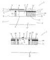
- FIG. 1 ais a longitudinal section of a preferred transducer element for use in an acoustic powered telemetric biosensor constructed in accordance with the present invention, taken along lines A—A in FIGS. 2 a - 2 e;
- FIG. 1 bis a longitudinal section of the transducer element of FIG. 1 a, taken along lines B—B in FIGS. 2 a - 2 e;
- FIGS. 2 a - 2 eare cross sections of the transducer element, taken at the respective sections C, D, E, F and G shown in FIG. 1 a;
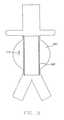
- FIG. 3shows the distribution of charge density across a piezoelectric layer of a preferred transducer element, resulting from the application of a constant pressure over the entire surface of the layer;
- FIG. 4shows the results of optimization performed for the power response of a preferred transducer element, constructed in accordance with the present invention
- FIG. 5shows a preferred electrode shape for maximizing the power response of a preferred transducer element, constructed in accordance with the present invention
- FIG. 6is a longitudinal section of an alternate preferred transducer element for use in an acoustic powered telemetric deep-implant biosensor constructed in accordance with the present invention, which is configured to function as a transmitter;
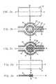
- FIGS. 7 a - 7 fare schematic views of possible configurations of acoustic biosensor transmitters constructed in accordance with the present invention, including parallel and anti-parallel electrical connections for controllably changing the mechanical impedance of the piezoelectric layer;
- FIG. 8is a longitudinal section of a preferred acoustic transmitter element constructed in accordance with the present invention, including an anti-parallel electrical connection;
- FIG. 9is a longitudinal section of another embodiment of an acoustic transmitter element constructed in accordance with the present invention.
- FIG. 10depicts a simplified abdominal aortic aneurysm in which an acoustic powered telemetric biosensor constructed in accordance with the present invention has been deployed in conjunction with a stent graft.
- an acoustic biosensor constructed in accordance with the present inventionfunctions to deliver physiologic data from an implantation site within a human or animal body to an external instrument.
- the biosensormay comprise any of a number of sensor types, such as a sensor selected from the group consisting of a pressure sensor, a temperature sensor, a position sensor, a tactility sensor, an electrical impedance sensor, a pH sensor, a blood sugar sensor, a blood oxygen sensor, a motion sensor, a flow sensor, a velocity sensor, an acceleration sensor, a force sensor, a strain sensor, an acoustics sensor, a moisture sensor, an osmolarity sensor, a light sensor, a turbidity sensor, a radiation sensor, an electrical energy sensor, an electromagnetic field sensor, a chemical sensor, an ionic sensor, and an enzyme sensor.
- the biosensormay comprise multiple sensors of a single type, or a mix of various types and quantities of sensors, depending on the implantation site and application
- a preferred biosensoris constructed in accordance with the teachings of U.S. patent application Ser. No. 09/303,644, which is fully incorporated by reference for all that it teaches and discloses.
- acoustic energy received from an externally originated interrogation signalis converted by a specially constructed piezoelectric transducer element into a current supply for powering one or more sensors embedded in the biosensor for measuring various biological parameters at the implantation site.
- the biosensoremploys a switching element to alternate the mechanical impedance of the transducer element to modulate the interrogation signal to thereby transmit the measured information, i.e., representative of the physiological condition at the implantation site, external to the body.
- a suitable transceiver outside of the bodymay be utilized to detect and interpret this modulated signal, as well as to emit the originating interrogation signal.
- an acoustic powered telemetric biosensor 172is shown implanted in an abdominal or thoracic aortic aneurysmal sac 180 in conjunction with a stent graft 182 .
- the biosensor 172provides for more precise monitoring of the aneurysmal sac 180 following the implantation of the stent graft 182 .
- the biosensor 172may occupy several possible positions relative to the stent graft 182 .
- the biosensor 172may be freely disposed within the aneurysmal sac 180 , as shown in FIG. 10 .
- the biosensor 172may be directly attached to the side of the stent graft 182 (not shown), or may be indirectly coupled to the stent graft 182 though a tether (not shown). Any changes in the pressure within the aneurysmal sac 180 , for example, may indicate the formation of a potentially dangerous endoleak. Because the biosensor 172 allows for non-invasive pressure measurements, aneurysmal pressure may be evaluated more conveniently and at more frequent intervals, and endoleaks may be more easily detected.
- Translumenal delivery of the biosensor 172is suitable for positioning the biosensor 172 in the aneuysmal sac 180 .
- Preferred methods and apparatus for delivering a biosensor to a desired implantation site within a human or animal bodyare provided in U.S. patent application Ser. Nos. 09/522,370, entitled “Systems and Methods for Deploying a Biosensor in Conjunction with a Prosthesis,” Ser. No. 09/522,724, entitled “Systems and Methods for Deploying a Biosensor with a Stent Graft,” and Ser. No.
- biosensor 172may also be placed in the aneurysmal sac 180 by a conventional surgical technique. Notably, multiple biosensors 172 may be placed in a given site, if desirable.
- FIGS. 1 a, 1 b and 2 a - 2 eillustrate a first preferred embodiment of a transducer element for use in an implantable acoustic biosensor (e.g., such as biosensor 172 in FIG. 10 ).
- an implantable acoustic biosensore.g., such as biosensor 172 in FIG. 10 .
- the transducer element 1includes at least one cell member 3 including a cavity 4 etched into a substrate and covered by a substantially flexible piezoelectric layer 2 . Attached to piezoelectric layer 2 are an upper electrode 8 and a lower electrode 6 , the electrodes for connection to an electronic circuit.
- the substrateis preferably made of an electrical conducting layer 11 disposed on an electrically insulating layer 12 , such that the cavity 4 is etched substantially through the thickness of electrically conducting layer 11 .
- Electrically conducting layer 11is preferably made of copper and insulating layer 12 is preferably made of a polymer such as polyimide.
- a polymersuch as polyimide.
- Conventional copper-plated polymer laminatesuch as KaptonTM sheets may be used for the production of transducer element 1 .
- commercially available laminatessuch as NovacladTM may be used.
- the substratemay include a silicon layer, or any other suitable material.
- layer 11is made of a non-conductive material such as PyralinTM.
- the cavity 4may be etched into the substrate by using conventional printed-circuit photolithography methods. Alternatively, the cavity 4 may be etched into the substrate by using VLSI/micro-machining technology or any other suitable technology.
- Piezoelectric layer 2may be made of PVDF or a copolymer thereof. Alternatively, piezoelectric layer 2 is made of a substantially flexible piezoceramic. Preferably, piezoelectric layer 2 is a poled PVDF sheet having a thickness of about 9-28 ⁇ m. Preferably, the thickness and radius of flexible layer 2 , as well as the pressure within cavity 4 , are specifically selected so as to provide a predetermined resonant frequency. When using the embodiment of FIGS. 1 a and 1 b, the radius of layer 2 is defined by the radius of cavity 4 .
- the present inventionallows to provide a miniature transducer element whose resonant frequency is such that the acoustic wavelength is much larger than the extent of the transducer. This enables the transducer to be omnidirectional even at resonance, and further allows the use of relatively low frequency acoustic signals which do not suffer from significant attenuation in the surrounding medium.
- the resonant frequencyrelates to the size of the element and speed of sound in the piezoceramic, and is higher by several orders of magnitude.
- the transducer of the present inventionis omnidirectional, i.e., insensitive to the direction of the impinging acoustic rays, thereby substantially simplifying the transducer's operation relative to other resonant devices.
- Such a transducer elementis thus suitable for application in confined or hidden locations, where the orientation of the transducer element cannot be ascertained in advance.
- the cavity 4features a circular or hexagonal shape with radius of about 200 ⁇ m.
- Electrically conducting layer 11preferably has a thickness of about 15 ⁇ m.
- Cell member 3is preferably etched completely through the thickness of electrically conducting layer 11 .
- Electrically insulating layer 12preferably features a thickness of about 50 ⁇ m. The precise dimensions of the various elements of a transducer element according to the present invention may be specifically tailored according to the requirements of the specific application.
- the cavity 4is preferably filled with a gas such as air, wherein the pressure of gas within cavity 4 may be specifically selected relative to the pressure external to the device (i.e., at the implantation site within a body), so as to adjust the sensitivity and ruggedness of the transducer, as well as the resonant frequency of layer 2 .
- a gassuch as air
- an insulating chamber 18is etched into the substrate, preferably through the thickness of conducting layer 11 , so as to insulate the transducer element from other portions of the substrate which may include other electrical components such as other transducer elements etched into the substrate.
- the width of insulating chamber 18is about 100 ⁇ m.
- the insulating chamber 18is etched into the substrate so as to form a wall 10 of a predetermined thickness, enclosing the cavity 4 .
- a conducting line 17is integrally made with wall 10 for connecting the transducer element to another electronic component, which is preferably etched into the same substrate, or to an external electronic circuit.
- upper electrode 8 and lower electrode 6attached to piezoelectric layer 2 are upper electrode 8 and lower electrode 6 .
- upper electrode 8 and lower electrode 6are preferably precisely shaped so as to cover a predetermined area of piezoelectric layer 2 .
- Electrodes 6 and 8may be deposited on the upper and lower surfaces of piezoelectric membrane 2 , respectively, by using various methods such as vacuum deposition, mask etching, painting, and the like.
- the lower electrode 6is preferably made as an integral part of a substantially thin electrically conducting layer 14 disposed on electrically conducting layer 11 .
- electrically conducting layer 14is made of a Nickel-Copper alloy and is attached to electrically conducting layer 11 by means of a sealing connection 16 , which may be made of indium.
- the sealing connection 16has a thickness of about 10 ⁇ m, such that the overall height of wall 10 of the cavity 4 is about 20-25 ⁇ m.
- electrically conducting layer 14covers the various portions of conducting layer 11 , including wall 10 and conducting line 17 .
- the portion of conducting layer 14 covering conducting line 17is for connection to an electronic component such as a neighboring cell.
- electrodes 6 and 8are specifically shaped to include the most energy-productive region of piezoelectric layer 2 . This configuration provides maximal response of the transducer while optimizing the electrode area, and therefore the cell capacitance, thereby maximizing a selected parameter such as voltage sensitivity, current sensitivity, or power sensitivity of the transducer element.
- ⁇ ( r, ⁇ )is time-dependent and represents the displacement of a selected point located on circular layer 2 , the specific location of which is given by radius r and angle ⁇ ;
- J and Iare the normal and modified Bessel functions of the first kind, respectively;
- P A , H Aare the air pressure within cavity 4 and the height of chamber 4 , respectively; and ⁇ W is the density of body fluid external to the cavity 4 (e.g., in the aneurysmal sac 180 in FIG. 10 ), once the biosensor 172 is implanted.
- the first term of the impedance Zrelates to the stiffness resulting from compression of air within cavity 4
- the second term of Zrelates to the mass added by the fluid boundary layer.
- An additional term of the impedance Z relating to the radiated acoustic energyis substantially negligible in this example.
- Q( r, ⁇ ,t)represents the charge density at a selected point located on circular layer 2 , the specific location of which is given by radius r and angle ⁇ ;
- xis the stretch direction of piezoelectric layer 2 ;
- yis the transverse direction (the direction perpendicular to the stretch direction) of layer 2 ;
- e 31 , e 32are off-diagonal elements of the piezoelectric strain coefficient tensor representing the charge accumulated at a selected point on layer 2 due to a given strain along the x and y directions, respectively, which coefficients being substantially dissimilar when using a PVDF layer.
- ⁇is the displacement of layer 2 , taken as the sum of the displacement for a given acoustic pressure P at frequency f, and the static displacement resulting from the pressure differential between the interior and exterior of cavity 4 , which displacements being extractable from the equations given above.
- ⁇is the dielectric constant of piezoelectric layer 2 ; and 2 h is the thickness of piezoelectric layer 2 .
- the DC components of Qare usually removed prior to the evaluation, since the DC currents are usually filtered out.
- the values of Q given aboverepresent peak values of the AC components of Q, and should be modified accordingly so as to obtain other required values such as RMS values.
- the electrical output of the transducerexpressed in terms of voltage, current and power responses depend on the AC components of Q, and on the shape S of the electrodes. Further, as can be seen from the above equations, the voltage response of the transducer may be substantially maximized by minimizing the area of the electrode. The current response, however, may be substantially maximized by maximizing the area of the electrode.
- FIG. 3shows the distribution of charge density on a circular piezoelectric layer 2 obtained as a result of pressure (acoustic and hydrostatic) applied uniformly over the entire area of layer 2 , wherein specific locations on layer 2 are herein defined by using Cartesian coordinates including the stretch direction (x direction) and the transverse direction (y direction) of layer 2 . It can be seen that distinct locations on layer 2 contribute differently to the charge density.
- the charge densityvanishes at the external periphery 70 and at the center 72 of layer 2 due to minimal deformation of these portions.
- the charge densityis maximal at two cores 74 a and 74 b located symmetrically on each side of center 72 due to maximal strains (in the stretch direction) of these portions.
- a preferred strategy for optimizing the electrical responses of the transduceris to shape the electrode by selecting the areas contributing at least a selected threshold percentage of the maximal charge density, wherein the threshold value is the parameter to be optimized.
- a threshold value of 0%relates to an electrode covering the entire area of layer 2 .
- FIG. 4shows the results of an optimization performed for the power response of a transducer having a layer 2 of a predetermined area.
- the threshold value which provides an optimal power responseis about 30% (graph b).
- an electrode which covers only the portions of layer 2 contributing at least 30% of the maximal charge densityyields a maximal power response.
- the pertinent voltage response obtained by such an electrodeis higher by a factor of 2 relative to an electrode completely covering layer 2 (graph a).
- the current response obtained by such electrodeis slightly lower relative to an electrode completely covering layer 2 (graph c).
- the deflection of layer 2is maximal when applying an acoustic signal at the resonant frequency of layer 2 (graph d).
- FIG. 5A preferred electrode shape for maximizing the power response of the transducer is shown in FIG. 5, wherein the electrode includes two electrode portions 80 a and 80 b substantially covering the maximal charge density portions of layer 2 , the electrode portions being interconnected by means of a connecting member 82 having a minimal area.
- portions 80 a and 80 bcover the portions of layer 2 , which yield at least a selected threshold (e.g. 30%) of the maximal charge density.
- electrodes 6 and 8other parameters may be optimized so as to determine the shape of electrodes 6 and 8 .
- one electrodeupper electrode 8 or lower electrode 6
- the other electrodecovering the entire area of layer 2 . Since the charge is collected only at the portions of layer 2 received between upper electrode 8 and lower electrode 6 , such configuration is operatively equivalent to a configuration including two shaped electrodes having identical shapes.
- chamber 4 of transducer element 1may contain gas of substantially low pressure, thereby conferring a substantially concave shape to piezoelectric membrane 2 at equilibrium.
- gas of substantially low pressurethereby conferring a substantially concave shape to piezoelectric membrane 2 at equilibrium.
- Such a configurationenables to further increase the electrical response of the transducer by increasing the total charge obtained for a given displacement of layer 2 .
- This preferred transducer constructionmakes it possible to increase the charge output of layer 2 for a given displacement, thereby increasing the voltage, current and power responses of the transducer without having to increase the acoustic pressure P. Also, this construction enables further miniaturization of the transducer element, same electrical response may obtain for smaller acoustic deflections. Such an embodiment is substantially more robust mechanically and therefore more durable than the embodiment shown in FIGS. 1 a and 1 b. Such further miniaturization of the transducer enables to use higher resonance frequencies relative to the embodiment shown in FIGS. 1 a and 1 b.
- a transducer element 1 according to the present inventionis fabricated by using technologies, which are in wide use in the microelectronics industry so as to allow integration thereof with other conventional electronic components.
- the transducer elementincludes a substrate such as Copper-polymer laminate or silicon, a variety of conventional electronic components may be fabricated onto the same substrate.
- a plurality of cavities 4may be etched into a single substrate 12 and covered by a single piezoelectric layer 2 so as to provide a transducer element including a matrix of transducing cells members 3 .
- the transducing cell members 3may be electrically interconnected in parallel or serial connections, or combinations thereof, so as to tailor the voltage and current response of the transducer. Parallel connections are preferably used so as to increase the current output while serial connections are preferably used so as to increase the voltage output of the transducer.
- piezoelectric layer 2may be completely depolarized and then re-polarized at specific regions thereof so as to provide a predetermined polarity to each of the transducing cell members 3 . This configuration enables to reduce the complexity of interconnections between the cell members 3 .
- a preferred biosensor transducer element according to the present inventionmay be further used as a transmitter element for transmitting information to a remote (e.g., external to the body) receiver by modulating the reflection of an external impinging acoustic wave arrived from a remote transmitter.
- a remotee.g., external to the body
- the transducer element shownmay function as a transmitter element due to the asymmetric fluctuations of piezoelectric layer 2 with respect to positive and negative transient acoustic pressures obtained as a result of the pressure differential between the interior and exterior of cavity 4 .
- a transmitter elementpreferably modulates the reflection of an external impinging acoustic wave by means of a switching element connected thereto.
- the switching elementencodes the information that is to be transmitted, such as the output of a sensor, thereby frequency modulating a reflected acoustic wave.
- Such configurationrequires very little expenditure of energy from the transmitting module itself, since the acoustic wave that is received is externally generated, such that the only energy required for transmission is the energy of modulation.
- the reflected acoustic signalis modulated by switching the switching element according to the frequency of a message electric signal arriving from another electronic component such as a sensor, so as to controllably change the mechanical impedance of layer 2 according to the frequency of the message signal.
- a specific array of electrodes connected to a single cell member 3 , or to a plurality of cell members,are used to control the mechanical impedance of layer 2 .
- FIGS. 7 a - 7 gillustrate possible configurations for controllably change the impedance of layer 2 of a transmitter element.
- a transmitter element according to the present inventionmay include a first and second pairs of electrodes, the first pair including an upper electrode 40 a and a lower electrode 38 a, and the second pair including an upper electrode 40 b and a lower electrode 38 b. Electrodes 38 a, 38 b, 40 a and 40 b are electrically connected to an electrical circuit by means of conducting lines 36 a, 36 b, 34 a and 34 b, respectively, the electrical circuit including a switching element (not shown) so as to alternately change the electrical connections of conducting lines 36 a, 36 b, 34 a and 34 b.
- the switching elementswitches between a parallel connection and an antiparallel connection of the electrodes.
- a parallel connectiondecreases the mechanical impedance of layer 2 , wherein an anti-parallel connection increases the mechanical impedance of layer 2 .
- An anti-parallel connectionmay be obtained by interconnecting line 34 a to 36 b and line 34 b to 36 a.
- a parallel connectionmay be obtained by connecting line 34 a to 34 b and line 36 a to 36 b.
- the switching frequencyequals the frequency of a message signal arriving from an electrical component such as a sensor.
- upper electrode 40 ais connected to lower electrode 38 b by means of a conducting line 28 , and electrodes 38 a and 40 b are connected to an electrical circuit by means of conducting lines 27 and 29 , respectively, the electrical circuit including a switching element.
- Such configurationprovides an anti-parallel connection of the electrodes, wherein the switching element functions as an on/off switch, thereby alternately increasing the mechanical impedance of layer 2 .
- layer 2may be depolarized and then re-polarized at specific regions thereof. As shown in FIG. 7 c, the polarity of the portion of layer 2 received between electrodes 40 a and 38 a is opposite to the polarity of the portion of layer 2 received between electrodes 40 b and 38 b.
- An anti-parallel connectionis thus achieved by interconnecting electrodes 38 a and 38 b by means of a conducting line 28 , and providing conducting lines 27 and 29 connected to electrodes 40 a and 40 b, respectively, the conducting lines for connection to an electrical circuit including a switching element.
- the transmitting elementincludes a plurality of transducing cell members, such that the mechanical impedance of layer 2 controllably changed by appropriately interconnecting the cell members.
- a first transducing cell member 3 a including a layer 2 a and a cavity 4 a, and a second transducing cell member 3 b including a layer 2 b and a cavity 4 bare preferably contained within the same substrate; and layers 2 a and 2 b are preferably integrally made (not shown).
- a first pair of electrodes including electrodes 6 a and 8 ais attached to layer 2
- a second pair of electrode including electrodes 6 b and 8 bis attached to layer 2 b.
- Electrodes 6 a, 8 a, 6 b and 8 bare electrically connected to an electrical circuit by means of conducting lines 37 a, 35 a, 37 b and 35 b, respectively, the electrical circuit including a switching element so as to alternately switch the electrical connections of conducting lines 37 a, 35 a, 37 b and 35 b so as to alternately provide parallel and anti-parallel connections, substantially as described for FIG. 7 a, thereby alternately decreasing and increasing the mechanical impedance of layers 2 a and 2 b.
- FIG. 7 eillustrates yet another embodiment, wherein the first and second transducing cell members are interconnected by means of an anti-parallel connection.
- the polarity of layer 2 ais opposite to the polarity of layer 2 b so as to reduce the complexity of the electrical connections between cell members 3 a and 3 b.
- electrode 6 ais connected to electrode 6 b by means of a conducting line 21
- electrodes 8 a and 8 bare provided with conducting lines 20 and 22 , respectively, for connection to an electrical circuit including a switching element, wherein the switching element preferably functions as an on/off switch so as to alternately increase the mechanical impedance of layers 2 a and 2 b.
- FIG. 7 fshows still another embodiment, wherein the first and second transducing cell members are interconnected by means of a parallel connection. Electrodes 6 a and 6 b are interconnected by means of conducting line 24 , electrodes 8 a and 8 b are interconnected by means of conducting line 23 , and electrodes 6 b and 8 b are provided with conducting lines 26 and 25 , respectively.
- the respective conducting lines for connection to an electrical circuitinclude a switching element, which preferably functions as an on/off switch for alternately decreasing and increasing the mechanical impedance of layers 2 a and 2 b.
- FIG. 8shows a possible configuration of two transducing cell members etched onto the same substrate and interconnected by means of an anti-parallel connection.
- the transducing cell membersare covered by a common piezoelectric layer 2 , wherein the polarity of the portion of layer 2 received between electrodes 6 a and 8 a is opposite to the polarity of the portion of layer 2 received between electrodes 6 b and 8 b.
- Electrodes 8 a and 8 bare bonded by means of a conducting line 9 and electrodes 6 a and 6 b are provided with conducting lines 16 for connection to an electrical circuit.
- FIG. 9Another preferred embodiment of an acoustic biosensor transmitter element is shown in FIG. 9, and includes a transducing cell member having a cavity 4 covered by a first and second piezoelectric layers, 50 a and 50 b, preferably having opposite polarities.
- layers 50 a and 50 bare interconnected by means of an insulating layer 52 .
- Attached to layer 50 aare upper and lower electrodes 44 a and 42 a, and attached to layer 50 b are upper and lower electrodes 44 b and 42 b.
- Electrodes 44 a, 42 a, 44 b and 42 bare provided with conducting lines 54 , 55 , 56 and 57 , respectively, for connection to an electrical circuit.
- the preferred acoustic biosensor embodiments described hereinemploy a transducer element to both convert acoustic energy to electrical power and to transmit the physiological information signal
- a transducer elementto both convert acoustic energy to electrical power and to transmit the physiological information signal
- a batterysuch as a lithium battery used in implantable pacemakers, may be employed in an implantable acoustic biosensor contemplated by the invention.
Landscapes
- Health & Medical Sciences (AREA)
- Life Sciences & Earth Sciences (AREA)
- Physics & Mathematics (AREA)
- Engineering & Computer Science (AREA)
- General Health & Medical Sciences (AREA)
- Public Health (AREA)
- Pathology (AREA)
- Veterinary Medicine (AREA)
- Biomedical Technology (AREA)
- Heart & Thoracic Surgery (AREA)
- Medical Informatics (AREA)
- Molecular Biology (AREA)
- Surgery (AREA)
- Animal Behavior & Ethology (AREA)
- Biophysics (AREA)
- Cardiology (AREA)
- Vascular Medicine (AREA)
- Physiology (AREA)
- General Physics & Mathematics (AREA)
- Neurosurgery (AREA)
- Fluid Mechanics (AREA)
- Hematology (AREA)
- Transplantation (AREA)
- Immunology (AREA)
- Computer Networks & Wireless Communication (AREA)
- Acoustics & Sound (AREA)
- Signal Processing (AREA)
- Ultra Sonic Daignosis Equipment (AREA)
Abstract
Description


Claims (6)
Priority Applications (2)
| Application Number | Priority Date | Filing Date | Title |
|---|---|---|---|
| US09/523,413US6475170B1 (en) | 1997-12-30 | 2000-03-10 | Acoustic biosensor for monitoring physiological conditions in a body implantation site |
| US09/872,129US6486588B2 (en) | 1997-12-30 | 2001-06-01 | Acoustic biosensor for monitoring physiological conditions in a body implantation site |
Applications Claiming Priority (3)
| Application Number | Priority Date | Filing Date | Title |
|---|---|---|---|
| US09/000,553US6140740A (en) | 1997-12-30 | 1997-12-30 | Piezoelectric transducer |
| US09/303,644US6432050B1 (en) | 1997-12-30 | 1999-05-03 | Implantable acoustic bio-sensing system and method |
| US09/523,413US6475170B1 (en) | 1997-12-30 | 2000-03-10 | Acoustic biosensor for monitoring physiological conditions in a body implantation site |
Related Parent Applications (2)
| Application Number | Title | Priority Date | Filing Date |
|---|---|---|---|
| US09/000,553Continuation-In-PartUS6140740A (en) | 1997-12-30 | 1997-12-30 | Piezoelectric transducer |
| US09/303,644Continuation-In-PartUS6432050B1 (en) | 1997-12-30 | 1999-05-03 | Implantable acoustic bio-sensing system and method |
Related Child Applications (1)
| Application Number | Title | Priority Date | Filing Date |
|---|---|---|---|
| US09/872,129ContinuationUS6486588B2 (en) | 1997-12-30 | 2001-06-01 | Acoustic biosensor for monitoring physiological conditions in a body implantation site |
Publications (1)
| Publication Number | Publication Date |
|---|---|
| US6475170B1true US6475170B1 (en) | 2002-11-05 |
Family
ID=46276697
Family Applications (1)
| Application Number | Title | Priority Date | Filing Date |
|---|---|---|---|
| US09/523,413Expired - LifetimeUS6475170B1 (en) | 1997-12-30 | 2000-03-10 | Acoustic biosensor for monitoring physiological conditions in a body implantation site |
Country Status (1)
| Country | Link |
|---|---|
| US (1) | US6475170B1 (en) |
Cited By (116)
| Publication number | Priority date | Publication date | Assignee | Title |
|---|---|---|---|---|
| US20020137991A1 (en)* | 1998-09-30 | 2002-09-26 | Scarantino Charles W. | Methods, systems, and associated implantable devices for dynamic monitoring of physiological and biological properties of tumors |
| US20030199772A1 (en)* | 2002-04-23 | 2003-10-23 | Michel Letort | Sensing device and method for determining aneurysmal pressure in a body cavity |
| US20030229388A1 (en)* | 2002-06-07 | 2003-12-11 | Hayashi Reid K. | Endovascular graft with pressure, temperature, flow and voltage sensors |
| WO2003103539A1 (en)* | 2002-06-07 | 2003-12-18 | Endovascular Technologies,Inc. | Endovascular graft with sensors design and attachment methods |
| US6702847B2 (en) | 2001-06-29 | 2004-03-09 | Scimed Life Systems, Inc. | Endoluminal device with indicator member for remote detection of endoleaks and/or changes in device morphology |
| US20050004478A1 (en)* | 2001-05-31 | 2005-01-06 | Fitz Matthew J. | Implantable device for monitoring aneurysm sac parameters |
| US6840956B1 (en)* | 2000-03-10 | 2005-01-11 | Remon Medical Technologies Ltd | Systems and methods for deploying a biosensor with a stent graft |
| US20050065592A1 (en)* | 2003-09-23 | 2005-03-24 | Asher Holzer | System and method of aneurism monitoring and treatment |
| US20050107866A1 (en)* | 2002-06-07 | 2005-05-19 | Brown Peter S. | Endovascular graft with pressor and attachment methods |
| US20050187594A1 (en)* | 2004-02-20 | 2005-08-25 | Hatlestad John D. | System and method for transmitting energy to and establishing a communications network with one or more implanted devices |
| US6953475B2 (en) | 1998-12-11 | 2005-10-11 | Endologix, Inc. | Bifurcation graft deployment catheter |
| US20060064143A1 (en)* | 2004-09-17 | 2006-03-23 | Cardiac Pacemakers, Inc. | Systems and methods for deriving relative physiologic measurements using a backend computing system |
| US20060064134A1 (en)* | 2004-09-17 | 2006-03-23 | Cardiac Pacemakers, Inc. | Systems and methods for deriving relative physiologic measurements |
| US7037335B2 (en)* | 2002-11-19 | 2006-05-02 | Eagle Vision, Inc. | Bulbous scleral implants for the treatment of eye disorders such as presbyopia and glaucoma |
| US20060107749A1 (en)* | 2004-11-22 | 2006-05-25 | Honeywell International Inc. | Disposable wireless pressure sensor |
| US20060122683A1 (en)* | 2004-12-07 | 2006-06-08 | Scimed Life Systems, Inc. | Medical device that signals lumen loss |
| US20060276870A1 (en)* | 2005-06-03 | 2006-12-07 | Mcginnis William J | Osseus stimulating electrodes |
| US7211048B1 (en) | 2002-10-07 | 2007-05-01 | Integrated Sensing Systems, Inc. | System for monitoring conduit obstruction |
| US20070142727A1 (en)* | 2005-12-15 | 2007-06-21 | Cardiac Pacemakers, Inc. | System and method for analyzing cardiovascular pressure measurements made within a human body |
| US20070208390A1 (en)* | 2006-03-01 | 2007-09-06 | Von Arx Jeffrey A | Implantable wireless sound sensor |
| US20070249950A1 (en)* | 2006-04-20 | 2007-10-25 | Thomas Piaget | Implanted air passage sensors |
| US20080021325A1 (en)* | 2006-06-12 | 2008-01-24 | Drost Cornelis J | System and method of perivascular pressure and flow measurement |
| US20080051838A1 (en)* | 2006-08-24 | 2008-02-28 | Shuros Allan C | Integrated cardiac rhythm management system with heart valve |
| US20080168921A1 (en)* | 2002-08-16 | 2008-07-17 | Uhland Scott A | Method for making device for controlled reservoir opening by electrothermal ablation |
| US20080246629A1 (en)* | 2007-04-04 | 2008-10-09 | The Hong Kong University Of Science And Technology | Mobile devices as centers for health information, monitoring and services |
| US20090036754A1 (en)* | 2007-07-31 | 2009-02-05 | Captomed Eurl | Self-calibrating pressure sensor |
| US7522962B1 (en) | 2004-12-03 | 2009-04-21 | Remon Medical Technologies, Ltd | Implantable medical device with integrated acoustic transducer |
| US7570998B2 (en) | 2005-08-26 | 2009-08-04 | Cardiac Pacemakers, Inc. | Acoustic communication transducer in implantable medical device header |
| US7572228B2 (en) | 2004-01-13 | 2009-08-11 | Remon Medical Technologies Ltd | Devices for fixing a sensor in a lumen |
| US7580750B2 (en) | 2004-11-24 | 2009-08-25 | Remon Medical Technologies, Ltd. | Implantable medical device with integrated acoustic transducer |
| US7615012B2 (en) | 2005-08-26 | 2009-11-10 | Cardiac Pacemakers, Inc. | Broadband acoustic sensor for an implantable medical device |
| US7621905B2 (en) | 1997-12-30 | 2009-11-24 | Remon Medical Technologies Ltd. | Devices for intrabody delivery of molecules and systems and methods utilizing same |
| US7634318B2 (en) | 2007-06-14 | 2009-12-15 | Cardiac Pacemakers, Inc. | Multi-element acoustic recharging system |
| US7641619B2 (en) | 2000-10-16 | 2010-01-05 | Remon Medical Technologies, Ltd. | Barometric pressure correction based on remote sources of information |
| US7658196B2 (en) | 2005-02-24 | 2010-02-09 | Ethicon Endo-Surgery, Inc. | System and method for determining implanted device orientation |
| US7686762B1 (en) | 2002-10-03 | 2010-03-30 | Integrated Sensing Systems, Inc. | Wireless device and system for monitoring physiologic parameters |
| US7742815B2 (en) | 2005-09-09 | 2010-06-22 | Cardiac Pacemakers, Inc. | Using implanted sensors for feedback control of implanted medical devices |
| US7775966B2 (en) | 2005-02-24 | 2010-08-17 | Ethicon Endo-Surgery, Inc. | Non-invasive pressure measurement in a fluid adjustable restrictive device |
| US7775215B2 (en) | 2005-02-24 | 2010-08-17 | Ethicon Endo-Surgery, Inc. | System and method for determining implanted device positioning and obtaining pressure data |
| US7813808B1 (en) | 2004-11-24 | 2010-10-12 | Remon Medical Technologies Ltd | Implanted sensor system with optimized operational and sensing parameters |
| US7844342B2 (en) | 2008-02-07 | 2010-11-30 | Ethicon Endo-Surgery, Inc. | Powering implantable restriction systems using light |
| US20110054333A1 (en)* | 2009-08-28 | 2011-03-03 | Stentronics, Inc. | Stent Flow Sensor |
| US7912548B2 (en) | 2006-07-21 | 2011-03-22 | Cardiac Pacemakers, Inc. | Resonant structures for implantable devices |
| US7927270B2 (en) | 2005-02-24 | 2011-04-19 | Ethicon Endo-Surgery, Inc. | External mechanical pressure sensor for gastric band pressure measurements |
| US7949396B2 (en) | 2006-07-21 | 2011-05-24 | Cardiac Pacemakers, Inc. | Ultrasonic transducer for a metallic cavity implated medical device |
| US7955268B2 (en) | 2006-07-21 | 2011-06-07 | Cardiac Pacemakers, Inc. | Multiple sensor deployment |
| US20110184245A1 (en)* | 2010-01-28 | 2011-07-28 | Warsaw Orthopedic, Inc., An Indiana Corporation | Tissue monitoring surgical retractor system |
| US8016745B2 (en) | 2005-02-24 | 2011-09-13 | Ethicon Endo-Surgery, Inc. | Monitoring of a food intake restriction device |
| US8016744B2 (en) | 2005-02-24 | 2011-09-13 | Ethicon Endo-Surgery, Inc. | External pressure-based gastric band adjustment system and method |
| US8034100B2 (en) | 1999-03-11 | 2011-10-11 | Endologix, Inc. | Graft deployment system |
| US8034065B2 (en) | 2008-02-26 | 2011-10-11 | Ethicon Endo-Surgery, Inc. | Controlling pressure in adjustable restriction devices |
| US8057492B2 (en) | 2008-02-12 | 2011-11-15 | Ethicon Endo-Surgery, Inc. | Automatically adjusting band system with MEMS pump |
| US8057399B2 (en) | 2006-09-15 | 2011-11-15 | Cardiac Pacemakers, Inc. | Anchor for an implantable sensor |
| US8060214B2 (en) | 2006-01-05 | 2011-11-15 | Cardiac Pacemakers, Inc. | Implantable medical device with inductive coil configurable for mechanical fixation |
| US8066629B2 (en) | 2005-02-24 | 2011-11-29 | Ethicon Endo-Surgery, Inc. | Apparatus for adjustment and sensing of gastric band pressure |
| US8082041B1 (en) | 2007-06-15 | 2011-12-20 | Piezo Energy Technologies, LLC | Bio-implantable ultrasound energy capture and storage assembly including transmitter and receiver cooling |
| US8100870B2 (en) | 2007-12-14 | 2012-01-24 | Ethicon Endo-Surgery, Inc. | Adjustable height gastric restriction devices and methods |
| US8114345B2 (en) | 2008-02-08 | 2012-02-14 | Ethicon Endo-Surgery, Inc. | System and method of sterilizing an implantable medical device |
| US8118856B2 (en) | 2009-07-27 | 2012-02-21 | Endologix, Inc. | Stent graft |
| US8126736B2 (en) | 2009-01-23 | 2012-02-28 | Warsaw Orthopedic, Inc. | Methods and systems for diagnosing, treating, or tracking spinal disorders |
| US8142452B2 (en) | 2007-12-27 | 2012-03-27 | Ethicon Endo-Surgery, Inc. | Controlling pressure in adjustable restriction devices |
| US8152710B2 (en) | 2006-04-06 | 2012-04-10 | Ethicon Endo-Surgery, Inc. | Physiological parameter analysis for an implantable restriction device and a data logger |
| US8167925B2 (en) | 1999-03-11 | 2012-05-01 | Endologix, Inc. | Single puncture bifurcation graft deployment system |
| US8187162B2 (en) | 2008-03-06 | 2012-05-29 | Ethicon Endo-Surgery, Inc. | Reorientation port |
| US8187163B2 (en) | 2007-12-10 | 2012-05-29 | Ethicon Endo-Surgery, Inc. | Methods for implanting a gastric restriction device |
| US8192350B2 (en) | 2008-01-28 | 2012-06-05 | Ethicon Endo-Surgery, Inc. | Methods and devices for measuring impedance in a gastric restriction system |
| US8204599B2 (en) | 2007-05-02 | 2012-06-19 | Cardiac Pacemakers, Inc. | System for anchoring an implantable sensor in a vessel |
| US8216295B2 (en) | 2008-07-01 | 2012-07-10 | Endologix, Inc. | Catheter system and methods of using same |
| US8221494B2 (en) | 2008-02-22 | 2012-07-17 | Endologix, Inc. | Apparatus and method of placement of a graft or graft system |
| US8221439B2 (en) | 2008-02-07 | 2012-07-17 | Ethicon Endo-Surgery, Inc. | Powering implantable restriction systems using kinetic motion |
| US8233995B2 (en) | 2008-03-06 | 2012-07-31 | Ethicon Endo-Surgery, Inc. | System and method of aligning an implantable antenna |
| US8236040B2 (en) | 2008-04-11 | 2012-08-07 | Endologix, Inc. | Bifurcated graft deployment systems and methods |
| US8317776B2 (en) | 2007-12-18 | 2012-11-27 | The Invention Science Fund I, Llc | Circulatory monitoring systems and methods |
| US8337389B2 (en) | 2008-01-28 | 2012-12-25 | Ethicon Endo-Surgery, Inc. | Methods and devices for diagnosing performance of a gastric restriction system |
| US8369960B2 (en) | 2008-02-12 | 2013-02-05 | Cardiac Pacemakers, Inc. | Systems and methods for controlling wireless signal transfers between ultrasound-enabled medical devices |
| US8377079B2 (en) | 2007-12-27 | 2013-02-19 | Ethicon Endo-Surgery, Inc. | Constant force mechanisms for regulating restriction devices |
| US8409132B2 (en) | 2007-12-18 | 2013-04-02 | The Invention Science Fund I, Llc | Treatment indications informed by a priori implant information |
| US8491646B2 (en) | 2009-07-15 | 2013-07-23 | Endologix, Inc. | Stent graft |
| US8523931B2 (en) | 2007-01-12 | 2013-09-03 | Endologix, Inc. | Dual concentric guidewire and methods of bifurcated graft deployment |
| US8591423B2 (en) | 2008-10-10 | 2013-11-26 | Cardiac Pacemakers, Inc. | Systems and methods for determining cardiac output using pulmonary artery pressure measurements |
| US8591395B2 (en) | 2008-01-28 | 2013-11-26 | Ethicon Endo-Surgery, Inc. | Gastric restriction device data handling devices and methods |
| US8591532B2 (en) | 2008-02-12 | 2013-11-26 | Ethicon Endo-Sugery, Inc. | Automatically adjusting band system |
| US8632470B2 (en) | 2008-11-19 | 2014-01-21 | Cardiac Pacemakers, Inc. | Assessment of pulmonary vascular resistance via pulmonary artery pressure |
| US8636670B2 (en) | 2008-05-13 | 2014-01-28 | The Invention Science Fund I, Llc | Circulatory monitoring systems and methods |
| US8649875B2 (en) | 2005-09-10 | 2014-02-11 | Artann Laboratories Inc. | Systems for remote generation of electrical signal in tissue based on time-reversal acoustics |
| US8676349B2 (en) | 2006-09-15 | 2014-03-18 | Cardiac Pacemakers, Inc. | Mechanism for releasably engaging an implantable medical device for implantation |
| US8685093B2 (en) | 2009-01-23 | 2014-04-01 | Warsaw Orthopedic, Inc. | Methods and systems for diagnosing, treating, or tracking spinal disorders |
| US8694129B2 (en) | 2009-02-13 | 2014-04-08 | Cardiac Pacemakers, Inc. | Deployable sensor platform on the lead system of an implantable device |
| US8725260B2 (en) | 2008-02-11 | 2014-05-13 | Cardiac Pacemakers, Inc | Methods of monitoring hemodynamic status for rhythm discrimination within the heart |
| US8808350B2 (en) | 2011-03-01 | 2014-08-19 | Endologix, Inc. | Catheter system and methods of using same |
| US8825161B1 (en) | 2007-05-17 | 2014-09-02 | Cardiac Pacemakers, Inc. | Acoustic transducer for an implantable medical device |
| US8870742B2 (en) | 2006-04-06 | 2014-10-28 | Ethicon Endo-Surgery, Inc. | GUI for an implantable restriction device and a data logger |
| US8915866B2 (en) | 2008-01-18 | 2014-12-23 | Warsaw Orthopedic, Inc. | Implantable sensor and associated methods |
| US8934987B2 (en) | 2008-07-15 | 2015-01-13 | Cardiac Pacemakers, Inc. | Implant assist apparatus for acoustically enabled implantable medical device |
| US8945202B2 (en) | 2009-04-28 | 2015-02-03 | Endologix, Inc. | Fenestrated prosthesis |
| US8974366B1 (en) | 2012-01-10 | 2015-03-10 | Piezo Energy Technologies, LLC | High power ultrasound wireless transcutaneous energy transfer (US-TET) source |
| US9108018B2 (en) | 2006-04-20 | 2015-08-18 | Limflow Gmbh | Methods for fluid flow through body passages |
| US20150342469A1 (en)* | 2012-12-21 | 2015-12-03 | Heraeus Deutschland GmbH & Co. KG | Thin metal membrane with support |
| US9314329B2 (en) | 2013-03-08 | 2016-04-19 | Limflow Gmbh | Methods and systems for providing or maintaining fluid flow through body passages |
| US9393100B2 (en) | 2010-11-17 | 2016-07-19 | Endologix, Inc. | Devices and methods to treat vascular dissections |
| US9545263B2 (en) | 2014-06-19 | 2017-01-17 | Limflow Gmbh | Devices and methods for treating lower extremity vasculature |
| US9579103B2 (en) | 2009-05-01 | 2017-02-28 | Endologix, Inc. | Percutaneous method and device to treat dissections |
| US9757574B2 (en) | 2015-05-11 | 2017-09-12 | Rainbow Medical Ltd. | Dual chamber transvenous pacemaker |
| EP3278823A1 (en)* | 2016-08-04 | 2018-02-07 | Roche Diabetes Care GmbH | Device for monitoring the flow of a fluid in a fluid administration system |
| US10390714B2 (en) | 2005-01-12 | 2019-08-27 | Remon Medical Technologies, Ltd. | Devices for fixing a sensor in a lumen |
| US10398580B2 (en) | 2004-09-08 | 2019-09-03 | Limflow Gmbh | Minimally invasive surgical apparatus and methods |
| US10543308B2 (en) | 2017-04-10 | 2020-01-28 | Limflow Gmbh | Methods for routing a guidewire from a first vessel and through a second vessel in lower extremity vasculature |
| CN111466337A (en)* | 2020-05-19 | 2020-07-31 | 山东大学齐鲁医院 | Abdominal aortic aneurysm animal model and construction method thereof |
| US10772717B2 (en) | 2009-05-01 | 2020-09-15 | Endologix, Inc. | Percutaneous method and device to treat dissections |
| US10835367B2 (en) | 2013-03-08 | 2020-11-17 | Limflow Gmbh | Devices for fluid flow through body passages |
| US11116943B2 (en) | 2018-10-09 | 2021-09-14 | Limflow Gmbh | Methods for accessing pedal veins |
| US11129737B2 (en) | 2015-06-30 | 2021-09-28 | Endologix Llc | Locking assembly for coupling guidewire to delivery system |
| US11406518B2 (en) | 2010-11-02 | 2022-08-09 | Endologix Llc | Apparatus and method of placement of a graft or graft system |
| US11612397B2 (en) | 2019-11-01 | 2023-03-28 | Limflow Gmbh | Devices and methods for increasing blood perfusion to a distal extremity |
| US12218518B2 (en) | 2023-04-14 | 2025-02-04 | Ultrapower, Inc. | System and method for powering an implantable device using acoustic energy |
| US12407558B2 (en) | 2021-06-29 | 2025-09-02 | Ulink Labs, Inc. | Systems, devices, and methods for establishing a wireless link in a heterogeneous medium |
Citations (43)
| Publication number | Priority date | Publication date | Assignee | Title |
|---|---|---|---|---|
| US3568661A (en) | 1968-10-02 | 1971-03-09 | Us Health Education & Welfare | Frequency modulated ultrasound technique for measurement of fluid velocity |
| US3757770A (en) | 1971-02-22 | 1973-09-11 | Bio Tel Western | Physiological pressure sensing and telemetry means employing a diode connected transistor transducer |
| US4127110A (en) | 1976-05-24 | 1978-11-28 | Huntington Institute Of Applied Medical Research | Implantable pressure transducer |
| US4227407A (en) | 1978-11-30 | 1980-10-14 | Cornell Research Foundation, Inc. | Volume flow measurement system |
| WO1983003345A1 (en) | 1982-03-24 | 1983-10-13 | Rozario, Rodney, A. | Temporary microvascular occluder |
| US4519401A (en) | 1983-09-20 | 1985-05-28 | Case Western Reserve University | Pressure telemetry implant |
| US4541431A (en) | 1984-09-20 | 1985-09-17 | Telectronics Pty. Ltd. | Use of telemetry coil to replace magnetically activated reed switch in implantable devices |
| US4593703A (en) | 1976-06-21 | 1986-06-10 | Cosman Eric R | Telemetric differential pressure sensor with the improvement of a conductive shorted loop tuning element and a resonant circuit |
| US4600855A (en) | 1983-09-28 | 1986-07-15 | Medex, Inc. | Piezoelectric apparatus for measuring bodily fluid pressure within a conduit |
| US4653508A (en) | 1976-06-21 | 1987-03-31 | Cosman Eric R | Pressure-balanced telemetric pressure sensing system and method therefore |
| US4660568A (en) | 1976-06-21 | 1987-04-28 | Cosman Eric R | Telemetric differential pressure sensing system and method therefore |
| US4676255A (en) | 1985-07-03 | 1987-06-30 | Cosman Eric R | Telemetric in-vivo calibration method and apparatus using a negative pressure applicator |
| US4781715A (en) | 1986-04-30 | 1988-11-01 | Temple University Of The Commonwealth System Of Higher Education | Cardiac prosthesis having integral blood pressure sensor |
| US4846191A (en) | 1988-05-27 | 1989-07-11 | Data Sciences, Inc. | Device for chronic measurement of internal body pressure |
| US5024224A (en) | 1988-09-01 | 1991-06-18 | Storz Instrument Company | Method of readout of implanted hearing aid device and apparatus therefor |
| US5178153A (en) | 1984-03-08 | 1993-01-12 | Einzig Robert E | Fluid flow sensing apparatus for in vivo and industrial applications employing novel differential optical fiber pressure sensors |
| US5289821A (en) | 1993-06-30 | 1994-03-01 | Swartz William M | Method of ultrasonic Doppler monitoring of blood flow in a blood vessel |
| US5314457A (en) | 1993-04-08 | 1994-05-24 | Jeutter Dean C | Regenerative electrical |
| US5411551A (en) | 1992-08-05 | 1995-05-02 | Ultrasonic Sensing And Monitoring Systems, Inc. | Stent assembly with sensor |
| US5423334A (en) | 1993-02-01 | 1995-06-13 | C. R. Bard, Inc. | Implantable medical device characterization system |
| US5476488A (en) | 1993-12-15 | 1995-12-19 | Pacesetter, Inc. | Telemetry system power control for implantable medical devices |
| US5562714A (en) | 1995-02-03 | 1996-10-08 | Medtronic, Inc. | Magnetic field strength regulator for implant |
| US5571152A (en) | 1995-05-26 | 1996-11-05 | Light Sciences Limited Partnership | Microminiature illuminator for administering photodynamic therapy |
| WO1997001986A1 (en) | 1995-07-06 | 1997-01-23 | Thomas Jefferson University | Implantable sensor and system for measurement and control of blood constituent levels |
| US5628782A (en) | 1992-12-11 | 1997-05-13 | W. L. Gore & Associates, Inc. | Method of making a prosthetic vascular graft |
| WO1997033513A1 (en) | 1996-03-13 | 1997-09-18 | Lipomatrix Incorporated | Implantable biosensing transponder |
| WO1997047236A1 (en) | 1996-06-12 | 1997-12-18 | K-One Technologies | Wideband external pulse cardiac monitor |
| US5704352A (en) | 1995-11-22 | 1998-01-06 | Tremblay; Gerald F. | Implantable passive bio-sensor |
| US5733313A (en) | 1996-08-01 | 1998-03-31 | Exonix Corporation | RF coupled, implantable medical device with rechargeable back-up power source |
| US5735887A (en) | 1996-12-10 | 1998-04-07 | Exonix Corporation | Closed-loop, RF-coupled implanted medical device |
| US5741316A (en) | 1996-12-02 | 1998-04-21 | Light Sciences Limited Partnership | Electromagnetic coil configurations for power transmission through tissue |
| WO1998026716A1 (en) | 1996-12-18 | 1998-06-25 | Sailor Mohler | Piezoelectric sensor for blood pressure measurement |
| WO1998029030A1 (en) | 1997-01-03 | 1998-07-09 | Biosense Inc. | Pressure-sensing stent |
| US5807258A (en) | 1997-10-14 | 1998-09-15 | Cimochowski; George E. | Ultrasonic sensors for monitoring the condition of a vascular graft |
| US5832924A (en) | 1995-02-16 | 1998-11-10 | Medwave, Inc. | Method of positioning a sensor for determining blood pressure of an artery |
| US5843135A (en) | 1997-10-20 | 1998-12-01 | Medtronic, Inc. | Pacing system with lead having a single conductor for connecting to pressure sensor and electrode |
| US5873835A (en) | 1993-04-29 | 1999-02-23 | Scimed Life Systems, Inc. | Intravascular pressure and flow sensor |
| EP0897690A1 (en) | 1997-08-15 | 1999-02-24 | Rijksuniversiteit te Leiden | Pressure sensor for use in an artery |
| WO1999026530A1 (en) | 1997-11-25 | 1999-06-03 | Cimochowski George E | Endoluminal implant with parameter sensing capability |
| US5941249A (en)* | 1996-09-05 | 1999-08-24 | Maynard; Ronald S. | Distributed activator for a two-dimensional shape memory alloy |
| US5957950A (en) | 1997-01-21 | 1999-09-28 | Northwestern University Medical School | Vascular acoustic emission analysis in a balloon angioplasty system |
| WO1999059460A2 (en) | 1998-05-15 | 1999-11-25 | Biosys Ab (Publ) | A medical measuring system |
| WO2000016686A2 (en) | 1998-09-24 | 2000-03-30 | Data Sciences International, Inc. | Implantable sensor with wireless communication |
- 2000
- 2000-03-10USUS09/523,413patent/US6475170B1/ennot_activeExpired - Lifetime
Patent Citations (46)
| Publication number | Priority date | Publication date | Assignee | Title |
|---|---|---|---|---|
| US3568661A (en) | 1968-10-02 | 1971-03-09 | Us Health Education & Welfare | Frequency modulated ultrasound technique for measurement of fluid velocity |
| US3757770A (en) | 1971-02-22 | 1973-09-11 | Bio Tel Western | Physiological pressure sensing and telemetry means employing a diode connected transistor transducer |
| US4127110A (en) | 1976-05-24 | 1978-11-28 | Huntington Institute Of Applied Medical Research | Implantable pressure transducer |
| US4593703A (en) | 1976-06-21 | 1986-06-10 | Cosman Eric R | Telemetric differential pressure sensor with the improvement of a conductive shorted loop tuning element and a resonant circuit |
| US4660568A (en) | 1976-06-21 | 1987-04-28 | Cosman Eric R | Telemetric differential pressure sensing system and method therefore |
| US4653508A (en) | 1976-06-21 | 1987-03-31 | Cosman Eric R | Pressure-balanced telemetric pressure sensing system and method therefore |
| US4227407A (en) | 1978-11-30 | 1980-10-14 | Cornell Research Foundation, Inc. | Volume flow measurement system |
| WO1983003345A1 (en) | 1982-03-24 | 1983-10-13 | Rozario, Rodney, A. | Temporary microvascular occluder |
| US4519401A (en) | 1983-09-20 | 1985-05-28 | Case Western Reserve University | Pressure telemetry implant |
| US4600855A (en) | 1983-09-28 | 1986-07-15 | Medex, Inc. | Piezoelectric apparatus for measuring bodily fluid pressure within a conduit |
| US5178153A (en) | 1984-03-08 | 1993-01-12 | Einzig Robert E | Fluid flow sensing apparatus for in vivo and industrial applications employing novel differential optical fiber pressure sensors |
| US4541431A (en) | 1984-09-20 | 1985-09-17 | Telectronics Pty. Ltd. | Use of telemetry coil to replace magnetically activated reed switch in implantable devices |
| US4676255A (en) | 1985-07-03 | 1987-06-30 | Cosman Eric R | Telemetric in-vivo calibration method and apparatus using a negative pressure applicator |
| US4781715A (en) | 1986-04-30 | 1988-11-01 | Temple University Of The Commonwealth System Of Higher Education | Cardiac prosthesis having integral blood pressure sensor |
| US4846191A (en) | 1988-05-27 | 1989-07-11 | Data Sciences, Inc. | Device for chronic measurement of internal body pressure |
| US5024224A (en) | 1988-09-01 | 1991-06-18 | Storz Instrument Company | Method of readout of implanted hearing aid device and apparatus therefor |
| US5411551A (en) | 1992-08-05 | 1995-05-02 | Ultrasonic Sensing And Monitoring Systems, Inc. | Stent assembly with sensor |
| US5628782A (en) | 1992-12-11 | 1997-05-13 | W. L. Gore & Associates, Inc. | Method of making a prosthetic vascular graft |
| US5423334A (en) | 1993-02-01 | 1995-06-13 | C. R. Bard, Inc. | Implantable medical device characterization system |
| US5314457A (en) | 1993-04-08 | 1994-05-24 | Jeutter Dean C | Regenerative electrical |
| US5873835A (en) | 1993-04-29 | 1999-02-23 | Scimed Life Systems, Inc. | Intravascular pressure and flow sensor |
| US5289821A (en) | 1993-06-30 | 1994-03-01 | Swartz William M | Method of ultrasonic Doppler monitoring of blood flow in a blood vessel |
| US5476488A (en) | 1993-12-15 | 1995-12-19 | Pacesetter, Inc. | Telemetry system power control for implantable medical devices |
| US5562714A (en) | 1995-02-03 | 1996-10-08 | Medtronic, Inc. | Magnetic field strength regulator for implant |
| US5832924A (en) | 1995-02-16 | 1998-11-10 | Medwave, Inc. | Method of positioning a sensor for determining blood pressure of an artery |
| US5571152A (en) | 1995-05-26 | 1996-11-05 | Light Sciences Limited Partnership | Microminiature illuminator for administering photodynamic therapy |
| WO1997001986A1 (en) | 1995-07-06 | 1997-01-23 | Thomas Jefferson University | Implantable sensor and system for measurement and control of blood constituent levels |
| US5704352A (en) | 1995-11-22 | 1998-01-06 | Tremblay; Gerald F. | Implantable passive bio-sensor |
| US5833603A (en) | 1996-03-13 | 1998-11-10 | Lipomatrix, Inc. | Implantable biosensing transponder |
| WO1997033513A1 (en) | 1996-03-13 | 1997-09-18 | Lipomatrix Incorporated | Implantable biosensing transponder |
| WO1997047236A1 (en) | 1996-06-12 | 1997-12-18 | K-One Technologies | Wideband external pulse cardiac monitor |
| US5733313A (en) | 1996-08-01 | 1998-03-31 | Exonix Corporation | RF coupled, implantable medical device with rechargeable back-up power source |
| US5941249A (en)* | 1996-09-05 | 1999-08-24 | Maynard; Ronald S. | Distributed activator for a two-dimensional shape memory alloy |
| US5741316A (en) | 1996-12-02 | 1998-04-21 | Light Sciences Limited Partnership | Electromagnetic coil configurations for power transmission through tissue |
| US5735887A (en) | 1996-12-10 | 1998-04-07 | Exonix Corporation | Closed-loop, RF-coupled implanted medical device |
| WO1998026716A1 (en) | 1996-12-18 | 1998-06-25 | Sailor Mohler | Piezoelectric sensor for blood pressure measurement |
| WO1998029030A1 (en) | 1997-01-03 | 1998-07-09 | Biosense Inc. | Pressure-sensing stent |
| US6053873A (en) | 1997-01-03 | 2000-04-25 | Biosense, Inc. | Pressure-sensing stent |
| US5957950A (en) | 1997-01-21 | 1999-09-28 | Northwestern University Medical School | Vascular acoustic emission analysis in a balloon angioplasty system |
| EP0897690A1 (en) | 1997-08-15 | 1999-02-24 | Rijksuniversiteit te Leiden | Pressure sensor for use in an artery |
| US5807258A (en) | 1997-10-14 | 1998-09-15 | Cimochowski; George E. | Ultrasonic sensors for monitoring the condition of a vascular graft |
| US5843135A (en) | 1997-10-20 | 1998-12-01 | Medtronic, Inc. | Pacing system with lead having a single conductor for connecting to pressure sensor and electrode |
| WO1999026530A1 (en) | 1997-11-25 | 1999-06-03 | Cimochowski George E | Endoluminal implant with parameter sensing capability |
| US5967986A (en) | 1997-11-25 | 1999-10-19 | Vascusense, Inc. | Endoluminal implant with fluid flow sensing capability |
| WO1999059460A2 (en) | 1998-05-15 | 1999-11-25 | Biosys Ab (Publ) | A medical measuring system |
| WO2000016686A2 (en) | 1998-09-24 | 2000-03-30 | Data Sciences International, Inc. | Implantable sensor with wireless communication |
Non-Patent Citations (12)
| Title |
|---|
| C. Hierold et al. (Germany, 1998) "Implantable Low Power Integrated Pressure Sensor System For Minimal Invasive Telemetric Patient Monitoring" IEEE, pp. 568-573. |
| Dipl.-Ing. Torsten Eggers et al. (Germany) "Implantable Telemetric Endosystem (ITES)" IMSAS Institut Fur Mikrosensoren-Aktuatoren Und-Systeme. 2 pp. |
| Dr. Hartmut Runge (Germany, May 1998) "Implanted blood pressure sensor reduces risk of infection for patients hospitalized for long-term observation" Siemens Press Release pp. 1-2. |
| E. R. Cosman et. al. (Massachussetts, Apr. 1979) "A Telemetric Pressure Sensor for Ventricular Shunt Systems" Surgical Neurology vol. 11, No. 4, pp. 287-294. |
| G. W. H. Schurink et al. (1998) "Late Endoleak After Endovascular Therapy for Abdominal Aortic Aneurysm", Eur. J. Vasc. Endovasc. Surg. vol. 17, pp. 448-450. |
| GH White et al. (1997) "Endoleak Following Endoluminal Repair of AAA: Management Options and Patient Outcomes", J Endovasc Surg, p. I-45. |
| Karl E. Richard et al. (Germany, Jan. 1999) "First clinical results with a telemetric shunt-integrated ICP-sensor" Neurological Research vol. 21, pp. 117-120. |
| Prof. Dr. Johannes Zacheja et al. (Germany, Sep. 1996) "An Implantable Microsystem For Biomedical Applications" Micro System Technologies 96, pp. 717-722. |
| S. K. Gupta et al. (1999) "Use of a Piezoelectric Film Sensor for Monitoring Vascular Grafts" The American Journal of Surgery vol. 160, pp. 182-186. |
| T. A. Cochran et al. (1990) "Aortic Aneurysm Abdominal", Current Therapy in Adult Medicine, Fourth Edition. |
| T. Chuter et al. (Sweden, Jan. 1997) "Aneurysm Pressure following Endovascular Exclusion" Eur. J. Vasc. Endovasc. Surg. vol. 13, pp. 85-87. |
| Z. Tang et al. (May 1995) "Data Transmission from an Implantable Biotelemeter by Load-Shift Keying Using Circuit Configuration Modulator" IEEE Transactions on Biomedical Engineering. vol. 42, No. 5, pp. 524-528. |
Cited By (205)
| Publication number | Priority date | Publication date | Assignee | Title |
|---|---|---|---|---|
| US8647328B2 (en) | 1997-12-30 | 2014-02-11 | Remon Medical Technologies, Ltd. | Reflected acoustic wave modulation |
| US7621905B2 (en) | 1997-12-30 | 2009-11-24 | Remon Medical Technologies Ltd. | Devices for intrabody delivery of molecules and systems and methods utilizing same |
| US7948148B2 (en) | 1997-12-30 | 2011-05-24 | Remon Medical Technologies Ltd. | Piezoelectric transducer |
| US8277441B2 (en) | 1997-12-30 | 2012-10-02 | Remon Medical Technologies, Ltd. | Piezoelectric transducer |
| US7756568B2 (en) | 1998-09-30 | 2010-07-13 | North Carolina State University | Methods, systems, and associated implantable devices for dynamic monitoring of physiological and biological properties of tumors |
| US9662049B2 (en) | 1998-09-30 | 2017-05-30 | North Carolina State University | Methods and systems for monitoring patients undergoing treatment for cancer |
| US7778692B2 (en) | 1998-09-30 | 2010-08-17 | North Carolina State University | Methods, systems, and associated implantable devices for detecting radiation in patients undergoing treatment for cancer |
| US7769431B2 (en) | 1998-09-30 | 2010-08-03 | North Carolina State University | Methods, systems, and associated implantable devices for detecting radiation in patients undergoing treatment for cancer |
| US20020137991A1 (en)* | 1998-09-30 | 2002-09-26 | Scarantino Charles W. | Methods, systems, and associated implantable devices for dynamic monitoring of physiological and biological properties of tumors |
| US7787937B2 (en) | 1998-09-30 | 2010-08-31 | North Carolina State University | Methods, systems, and associated implantable devices for detecting radiation in patients undergoing treatment for cancer |
| US6963771B2 (en) | 1998-09-30 | 2005-11-08 | North Carolina State University | Methods, systems, and associated implantable devices for radiation dose verification for therapies used to treat tumors |
| US6963770B2 (en) | 1998-09-30 | 2005-11-08 | North Carolina State University | Methods, systems, and associated implantable devices for dynamic monitoring of physiological and biological properties of tumors |
| US7010340B2 (en) | 1998-09-30 | 2006-03-07 | North Carolina State University | Methods, systems, and associated implantable devices for dynamic monitoring of physiological and biological properties of tumors |
| US8380290B2 (en) | 1998-09-30 | 2013-02-19 | North Carolina State University | Implantable devices for dynamic monitoring of physiological and biological properties of tumors |
| US8147535B2 (en) | 1998-12-11 | 2012-04-03 | Endologix, Inc. | Bifurcation graft deployment catheter |
| US6953475B2 (en) | 1998-12-11 | 2005-10-11 | Endologix, Inc. | Bifurcation graft deployment catheter |
| US8034100B2 (en) | 1999-03-11 | 2011-10-11 | Endologix, Inc. | Graft deployment system |
| US8167925B2 (en) | 1999-03-11 | 2012-05-01 | Endologix, Inc. | Single puncture bifurcation graft deployment system |
| US6840956B1 (en)* | 2000-03-10 | 2005-01-11 | Remon Medical Technologies Ltd | Systems and methods for deploying a biosensor with a stent graft |
| US7641619B2 (en) | 2000-10-16 | 2010-01-05 | Remon Medical Technologies, Ltd. | Barometric pressure correction based on remote sources of information |
| US20050004478A1 (en)* | 2001-05-31 | 2005-01-06 | Fitz Matthew J. | Implantable device for monitoring aneurysm sac parameters |
| US7344561B2 (en) | 2001-06-29 | 2008-03-18 | Boston Scientific Scimed, Inc. | Monitoring system for remote detection of endoleaks and/or changes in morphology of implanted endoluminal devices |
| US20040098093A1 (en)* | 2001-06-29 | 2004-05-20 | Dicarlo Paul | Monitoring system for remote detection of endoleaks and/or changes in morphology of implanted endoluminal devices |
| US6702847B2 (en) | 2001-06-29 | 2004-03-09 | Scimed Life Systems, Inc. | Endoluminal device with indicator member for remote detection of endoleaks and/or changes in device morphology |
| US20030199772A1 (en)* | 2002-04-23 | 2003-10-23 | Michel Letort | Sensing device and method for determining aneurysmal pressure in a body cavity |
| US7261733B1 (en) | 2002-06-07 | 2007-08-28 | Endovascular Technologies, Inc. | Endovascular graft with sensors design and attachment methods |
| US20060200220A1 (en)* | 2002-06-07 | 2006-09-07 | Brown Peter S | Endovascular graft with sensors design and attachment methods |
| US20050107866A1 (en)* | 2002-06-07 | 2005-05-19 | Brown Peter S. | Endovascular graft with pressor and attachment methods |
| US20060149347A1 (en)* | 2002-06-07 | 2006-07-06 | Hayashi Reid K | Endovascular graft with pressure, temperature, flow and voltage sensors |
| US20030229388A1 (en)* | 2002-06-07 | 2003-12-11 | Hayashi Reid K. | Endovascular graft with pressure, temperature, flow and voltage sensors |
| US7488345B2 (en)* | 2002-06-07 | 2009-02-10 | Endovascular Technologies, Inc. | Endovascular graft with pressor and attachment methods |
| WO2003103539A1 (en)* | 2002-06-07 | 2003-12-18 | Endovascular Technologies,Inc. | Endovascular graft with sensors design and attachment methods |
| US7025778B2 (en)* | 2002-06-07 | 2006-04-11 | Endovascular Technologies, Inc. | Endovascular graft with pressure, temperature, flow and voltage sensors |
| US20080168921A1 (en)* | 2002-08-16 | 2008-07-17 | Uhland Scott A | Method for making device for controlled reservoir opening by electrothermal ablation |
| US7910151B2 (en) | 2002-08-16 | 2011-03-22 | Microchips, Inc. | Method for making device for controlled reservoir opening by electrothermal ablation |
| US7455667B2 (en) | 2002-08-16 | 2008-11-25 | Microchips, Inc. | Controlled release device and method using electrothermal ablation |
| US8211092B2 (en) | 2002-08-16 | 2012-07-03 | Microchips, Inc. | Containment device with multi-layer reservoir cap structure |
| US20090030404A1 (en)* | 2002-08-16 | 2009-01-29 | Microchips, Inc. | Containment device with multi-layer reservoir cap structure |
| US7686762B1 (en) | 2002-10-03 | 2010-03-30 | Integrated Sensing Systems, Inc. | Wireless device and system for monitoring physiologic parameters |
| US7211048B1 (en) | 2002-10-07 | 2007-05-01 | Integrated Sensing Systems, Inc. | System for monitoring conduit obstruction |
| US7037335B2 (en)* | 2002-11-19 | 2006-05-02 | Eagle Vision, Inc. | Bulbous scleral implants for the treatment of eye disorders such as presbyopia and glaucoma |
| US20050065592A1 (en)* | 2003-09-23 | 2005-03-24 | Asher Holzer | System and method of aneurism monitoring and treatment |
| US9149193B2 (en) | 2004-01-13 | 2015-10-06 | Remon Medical Technologies Ltd | Devices for fixing a sensor in a lumen |
| US7572228B2 (en) | 2004-01-13 | 2009-08-11 | Remon Medical Technologies Ltd | Devices for fixing a sensor in a lumen |
| US20050187594A1 (en)* | 2004-02-20 | 2005-08-25 | Hatlestad John D. | System and method for transmitting energy to and establishing a communications network with one or more implanted devices |
| US7471986B2 (en) | 2004-02-20 | 2008-12-30 | Cardiac Pacemakers, Inc. | System and method for transmitting energy to and establishing a communications network with one or more implanted devices |
| US11446170B2 (en) | 2004-09-08 | 2022-09-20 | Limflow Gmbh | Minimally invasive surgical apparatus and methods |
| US10398580B2 (en) | 2004-09-08 | 2019-09-03 | Limflow Gmbh | Minimally invasive surgical apparatus and methods |
| US20060064142A1 (en)* | 2004-09-17 | 2006-03-23 | Cardiac Pacemakers, Inc. | Systems and methods for deriving relative physiologic measurements using an implanted sensor device |
| US20060064134A1 (en)* | 2004-09-17 | 2006-03-23 | Cardiac Pacemakers, Inc. | Systems and methods for deriving relative physiologic measurements |
| US20060064143A1 (en)* | 2004-09-17 | 2006-03-23 | Cardiac Pacemakers, Inc. | Systems and methods for deriving relative physiologic measurements using a backend computing system |
| US20060064133A1 (en)* | 2004-09-17 | 2006-03-23 | Cardiac Pacemakers, Inc. | System and method for deriving relative physiologic measurements using an external computing device |
| US8852099B2 (en) | 2004-09-17 | 2014-10-07 | Cardiac Pacemakers, Inc. | Systems and methods for deriving relative physiologic measurements |
| US8271093B2 (en) | 2004-09-17 | 2012-09-18 | Cardiac Pacemakers, Inc. | Systems and methods for deriving relative physiologic measurements using a backend computing system |
| US20060107749A1 (en)* | 2004-11-22 | 2006-05-25 | Honeywell International Inc. | Disposable wireless pressure sensor |
| US7059196B1 (en) | 2004-11-22 | 2006-06-13 | Honeywell International Inc. | Disposable wireless pressure sensor |
| US7580750B2 (en) | 2004-11-24 | 2009-08-25 | Remon Medical Technologies, Ltd. | Implantable medical device with integrated acoustic transducer |
| US7813808B1 (en) | 2004-11-24 | 2010-10-12 | Remon Medical Technologies Ltd | Implanted sensor system with optimized operational and sensing parameters |
| US8744580B2 (en) | 2004-11-24 | 2014-06-03 | Remon Medical Technologies, Ltd. | Implantable medical device with integrated acoustic transducer |
| US7522962B1 (en) | 2004-12-03 | 2009-04-21 | Remon Medical Technologies, Ltd | Implantable medical device with integrated acoustic transducer |
| US20060122683A1 (en)* | 2004-12-07 | 2006-06-08 | Scimed Life Systems, Inc. | Medical device that signals lumen loss |
| US8048141B2 (en)* | 2004-12-07 | 2011-11-01 | Boston Scientific Scimed, Inc. | Medical device that signals lumen loss |
| US10390714B2 (en) | 2005-01-12 | 2019-08-27 | Remon Medical Technologies, Ltd. | Devices for fixing a sensor in a lumen |
| US7927270B2 (en) | 2005-02-24 | 2011-04-19 | Ethicon Endo-Surgery, Inc. | External mechanical pressure sensor for gastric band pressure measurements |
| US7775215B2 (en) | 2005-02-24 | 2010-08-17 | Ethicon Endo-Surgery, Inc. | System and method for determining implanted device positioning and obtaining pressure data |
| US8016744B2 (en) | 2005-02-24 | 2011-09-13 | Ethicon Endo-Surgery, Inc. | External pressure-based gastric band adjustment system and method |
| US8016745B2 (en) | 2005-02-24 | 2011-09-13 | Ethicon Endo-Surgery, Inc. | Monitoring of a food intake restriction device |
| US7775966B2 (en) | 2005-02-24 | 2010-08-17 | Ethicon Endo-Surgery, Inc. | Non-invasive pressure measurement in a fluid adjustable restrictive device |
| US7658196B2 (en) | 2005-02-24 | 2010-02-09 | Ethicon Endo-Surgery, Inc. | System and method for determining implanted device orientation |
| US8066629B2 (en) | 2005-02-24 | 2011-11-29 | Ethicon Endo-Surgery, Inc. | Apparatus for adjustment and sensing of gastric band pressure |
| US20060276870A1 (en)* | 2005-06-03 | 2006-12-07 | Mcginnis William J | Osseus stimulating electrodes |
| US7615012B2 (en) | 2005-08-26 | 2009-11-10 | Cardiac Pacemakers, Inc. | Broadband acoustic sensor for an implantable medical device |
| US7570998B2 (en) | 2005-08-26 | 2009-08-04 | Cardiac Pacemakers, Inc. | Acoustic communication transducer in implantable medical device header |
| US7949394B2 (en) | 2005-09-09 | 2011-05-24 | Cardiac Pacemakers, Inc. | Using implanted sensors for feedback control of implanted medical devices |
| US7742815B2 (en) | 2005-09-09 | 2010-06-22 | Cardiac Pacemakers, Inc. | Using implanted sensors for feedback control of implanted medical devices |
| US8649875B2 (en) | 2005-09-10 | 2014-02-11 | Artann Laboratories Inc. | Systems for remote generation of electrical signal in tissue based on time-reversal acoustics |
| US20070142727A1 (en)* | 2005-12-15 | 2007-06-21 | Cardiac Pacemakers, Inc. | System and method for analyzing cardiovascular pressure measurements made within a human body |
| US8060214B2 (en) | 2006-01-05 | 2011-11-15 | Cardiac Pacemakers, Inc. | Implantable medical device with inductive coil configurable for mechanical fixation |
| US20070208390A1 (en)* | 2006-03-01 | 2007-09-06 | Von Arx Jeffrey A | Implantable wireless sound sensor |
| US8870742B2 (en) | 2006-04-06 | 2014-10-28 | Ethicon Endo-Surgery, Inc. | GUI for an implantable restriction device and a data logger |
| US8152710B2 (en) | 2006-04-06 | 2012-04-10 | Ethicon Endo-Surgery, Inc. | Physiological parameter analysis for an implantable restriction device and a data logger |
| US20070249950A1 (en)* | 2006-04-20 | 2007-10-25 | Thomas Piaget | Implanted air passage sensors |
| US9782201B2 (en) | 2006-04-20 | 2017-10-10 | Limflow Gmbh | Methods for fluid flow through body passages |
| US10390933B2 (en) | 2006-04-20 | 2019-08-27 | Limflow Gmbh | Devices for fluid flow through body vessels |
| US9326792B2 (en) | 2006-04-20 | 2016-05-03 | Limflow Gmbh | Methods for fluid flow through body passages |
| US7744542B2 (en) | 2006-04-20 | 2010-06-29 | Cardiac Pacemakers, Inc. | Implanted air passage sensors |
| US11241304B2 (en) | 2006-04-20 | 2022-02-08 | Limflow Gmbh | Method for fluid flow through body passages |
| US10136987B2 (en) | 2006-04-20 | 2018-11-27 | Limflow Gmbh | Devices for fluid flow through body passages |
| US9532803B2 (en) | 2006-04-20 | 2017-01-03 | Limflow Gmbh | Devices for fluid flow through body passages |
| US9108018B2 (en) | 2006-04-20 | 2015-08-18 | Limflow Gmbh | Methods for fluid flow through body passages |
| US20080021325A1 (en)* | 2006-06-12 | 2008-01-24 | Drost Cornelis J | System and method of perivascular pressure and flow measurement |
| US8968204B2 (en)* | 2006-06-12 | 2015-03-03 | Transonic Systems, Inc. | System and method of perivascular pressure and flow measurement |
| US8548592B2 (en) | 2006-07-21 | 2013-10-01 | Cardiac Pacemakers, Inc. | Ultrasonic transducer for a metallic cavity implanted medical device |
| US7912548B2 (en) | 2006-07-21 | 2011-03-22 | Cardiac Pacemakers, Inc. | Resonant structures for implantable devices |
| US7949396B2 (en) | 2006-07-21 | 2011-05-24 | Cardiac Pacemakers, Inc. | Ultrasonic transducer for a metallic cavity implated medical device |
| US7955268B2 (en) | 2006-07-21 | 2011-06-07 | Cardiac Pacemakers, Inc. | Multiple sensor deployment |
| US7643879B2 (en) | 2006-08-24 | 2010-01-05 | Cardiac Pacemakers, Inc. | Integrated cardiac rhythm management system with heart valve |
| US8239023B2 (en) | 2006-08-24 | 2012-08-07 | Cardiac Pacemakers, Inc. | Integrated cardiac rhythm management system with heart valve |
| US8504151B2 (en) | 2006-08-24 | 2013-08-06 | Cardiac Pacemakers, Inc. | Integrated cardiac rhythm management system with heart valve |
| US20080051838A1 (en)* | 2006-08-24 | 2008-02-28 | Shuros Allan C | Integrated cardiac rhythm management system with heart valve |
| US20100100144A1 (en)* | 2006-08-24 | 2010-04-22 | Shuros Allan C | Integrated cardiac rhythm management system with heart valve |
| US9713427B2 (en) | 2006-09-15 | 2017-07-25 | Cardiac Pacemakers, Inc. | Mechanism for releasably engaging an implantable medical device for implantation |
| US8676349B2 (en) | 2006-09-15 | 2014-03-18 | Cardiac Pacemakers, Inc. | Mechanism for releasably engaging an implantable medical device for implantation |
| US8057399B2 (en) | 2006-09-15 | 2011-11-15 | Cardiac Pacemakers, Inc. | Anchor for an implantable sensor |
| US9026229B2 (en) | 2006-09-15 | 2015-05-05 | Cardiac Pacemakers, Inc. | Mechanism for releasably engaging an implantable medical device for implantation |
| US8523931B2 (en) | 2007-01-12 | 2013-09-03 | Endologix, Inc. | Dual concentric guidewire and methods of bifurcated graft deployment |
| US20080246629A1 (en)* | 2007-04-04 | 2008-10-09 | The Hong Kong University Of Science And Technology | Mobile devices as centers for health information, monitoring and services |
| US8204599B2 (en) | 2007-05-02 | 2012-06-19 | Cardiac Pacemakers, Inc. | System for anchoring an implantable sensor in a vessel |
| US8825161B1 (en) | 2007-05-17 | 2014-09-02 | Cardiac Pacemakers, Inc. | Acoustic transducer for an implantable medical device |
| US8340778B2 (en) | 2007-06-14 | 2012-12-25 | Cardiac Pacemakers, Inc. | Multi-element acoustic recharging system |
| US9731141B2 (en) | 2007-06-14 | 2017-08-15 | Cardiac Pacemakers, Inc. | Multi-element acoustic recharging system |
| US7634318B2 (en) | 2007-06-14 | 2009-12-15 | Cardiac Pacemakers, Inc. | Multi-element acoustic recharging system |
| US8082041B1 (en) | 2007-06-15 | 2011-12-20 | Piezo Energy Technologies, LLC | Bio-implantable ultrasound energy capture and storage assembly including transmitter and receiver cooling |
| FR2919486A1 (en)* | 2007-07-31 | 2009-02-06 | Captomed Entpr Unipersonnelle | SELF-CALIBRAL PRESSURE SENSOR. |
| EP2022395A1 (en)* | 2007-07-31 | 2009-02-11 | Captomed EURL | Self-calibrating pressure sensor |
| US8622923B2 (en) | 2007-07-31 | 2014-01-07 | Captomed Eurl | Self-calibrating pressure sensor |
| US20090036754A1 (en)* | 2007-07-31 | 2009-02-05 | Captomed Eurl | Self-calibrating pressure sensor |
| US8187163B2 (en) | 2007-12-10 | 2012-05-29 | Ethicon Endo-Surgery, Inc. | Methods for implanting a gastric restriction device |
| US8100870B2 (en) | 2007-12-14 | 2012-01-24 | Ethicon Endo-Surgery, Inc. | Adjustable height gastric restriction devices and methods |
| US8403881B2 (en) | 2007-12-18 | 2013-03-26 | The Invention Science Fund I, Llc | Circulatory monitoring systems and methods |
| US8317776B2 (en) | 2007-12-18 | 2012-11-27 | The Invention Science Fund I, Llc | Circulatory monitoring systems and methods |
| US9717896B2 (en) | 2007-12-18 | 2017-08-01 | Gearbox, Llc | Treatment indications informed by a priori implant information |
| US8870813B2 (en) | 2007-12-18 | 2014-10-28 | The Invention Science Fund I, Llc | Circulatory monitoring systems and methods |
| US8409132B2 (en) | 2007-12-18 | 2013-04-02 | The Invention Science Fund I, Llc | Treatment indications informed by a priori implant information |
| US8142452B2 (en) | 2007-12-27 | 2012-03-27 | Ethicon Endo-Surgery, Inc. | Controlling pressure in adjustable restriction devices |
| US8377079B2 (en) | 2007-12-27 | 2013-02-19 | Ethicon Endo-Surgery, Inc. | Constant force mechanisms for regulating restriction devices |
| US8915866B2 (en) | 2008-01-18 | 2014-12-23 | Warsaw Orthopedic, Inc. | Implantable sensor and associated methods |
| US8192350B2 (en) | 2008-01-28 | 2012-06-05 | Ethicon Endo-Surgery, Inc. | Methods and devices for measuring impedance in a gastric restriction system |
| US8591395B2 (en) | 2008-01-28 | 2013-11-26 | Ethicon Endo-Surgery, Inc. | Gastric restriction device data handling devices and methods |
| US8337389B2 (en) | 2008-01-28 | 2012-12-25 | Ethicon Endo-Surgery, Inc. | Methods and devices for diagnosing performance of a gastric restriction system |
| US8221439B2 (en) | 2008-02-07 | 2012-07-17 | Ethicon Endo-Surgery, Inc. | Powering implantable restriction systems using kinetic motion |
| US7844342B2 (en) | 2008-02-07 | 2010-11-30 | Ethicon Endo-Surgery, Inc. | Powering implantable restriction systems using light |
| US8114345B2 (en) | 2008-02-08 | 2012-02-14 | Ethicon Endo-Surgery, Inc. | System and method of sterilizing an implantable medical device |
| US8725260B2 (en) | 2008-02-11 | 2014-05-13 | Cardiac Pacemakers, Inc | Methods of monitoring hemodynamic status for rhythm discrimination within the heart |
| US8369960B2 (en) | 2008-02-12 | 2013-02-05 | Cardiac Pacemakers, Inc. | Systems and methods for controlling wireless signal transfers between ultrasound-enabled medical devices |
| US8057492B2 (en) | 2008-02-12 | 2011-11-15 | Ethicon Endo-Surgery, Inc. | Automatically adjusting band system with MEMS pump |
| US8591532B2 (en) | 2008-02-12 | 2013-11-26 | Ethicon Endo-Sugery, Inc. | Automatically adjusting band system |
| US9149381B2 (en) | 2008-02-22 | 2015-10-06 | Endologix, Inc. | Apparatus and method of placement of a graft or graft system |
| US8672989B2 (en) | 2008-02-22 | 2014-03-18 | Endologix, Inc. | Apparatus and method of placement of a graft or graft system |
| US10245166B2 (en) | 2008-02-22 | 2019-04-02 | Endologix, Inc. | Apparatus and method of placement of a graft or graft system |
| US8221494B2 (en) | 2008-02-22 | 2012-07-17 | Endologix, Inc. | Apparatus and method of placement of a graft or graft system |
| US8034065B2 (en) | 2008-02-26 | 2011-10-11 | Ethicon Endo-Surgery, Inc. | Controlling pressure in adjustable restriction devices |
| US8233995B2 (en) | 2008-03-06 | 2012-07-31 | Ethicon Endo-Surgery, Inc. | System and method of aligning an implantable antenna |
| US8187162B2 (en) | 2008-03-06 | 2012-05-29 | Ethicon Endo-Surgery, Inc. | Reorientation port |
| US8236040B2 (en) | 2008-04-11 | 2012-08-07 | Endologix, Inc. | Bifurcated graft deployment systems and methods |
| US8357192B2 (en) | 2008-04-11 | 2013-01-22 | Endologix, Inc. | Bifurcated graft deployment systems and methods |
| US8764812B2 (en) | 2008-04-11 | 2014-07-01 | Endologix, Inc. | Bifurcated graft deployment systems and methods |
| US8636670B2 (en) | 2008-05-13 | 2014-01-28 | The Invention Science Fund I, Llc | Circulatory monitoring systems and methods |
| US9700701B2 (en) | 2008-07-01 | 2017-07-11 | Endologix, Inc. | Catheter system and methods of using same |
| US8216295B2 (en) | 2008-07-01 | 2012-07-10 | Endologix, Inc. | Catheter system and methods of using same |
| US10512758B2 (en) | 2008-07-01 | 2019-12-24 | Endologix, Inc. | Catheter system and methods of using same |
| US8934987B2 (en) | 2008-07-15 | 2015-01-13 | Cardiac Pacemakers, Inc. | Implant assist apparatus for acoustically enabled implantable medical device |
| US8591423B2 (en) | 2008-10-10 | 2013-11-26 | Cardiac Pacemakers, Inc. | Systems and methods for determining cardiac output using pulmonary artery pressure measurements |
| US8632470B2 (en) | 2008-11-19 | 2014-01-21 | Cardiac Pacemakers, Inc. | Assessment of pulmonary vascular resistance via pulmonary artery pressure |
| US8126736B2 (en) | 2009-01-23 | 2012-02-28 | Warsaw Orthopedic, Inc. | Methods and systems for diagnosing, treating, or tracking spinal disorders |
| US8685093B2 (en) | 2009-01-23 | 2014-04-01 | Warsaw Orthopedic, Inc. | Methods and systems for diagnosing, treating, or tracking spinal disorders |
| US8694129B2 (en) | 2009-02-13 | 2014-04-08 | Cardiac Pacemakers, Inc. | Deployable sensor platform on the lead system of an implantable device |
| US10603196B2 (en) | 2009-04-28 | 2020-03-31 | Endologix, Inc. | Fenestrated prosthesis |
| US8945202B2 (en) | 2009-04-28 | 2015-02-03 | Endologix, Inc. | Fenestrated prosthesis |
| US9579103B2 (en) | 2009-05-01 | 2017-02-28 | Endologix, Inc. | Percutaneous method and device to treat dissections |
| US10772717B2 (en) | 2009-05-01 | 2020-09-15 | Endologix, Inc. | Percutaneous method and device to treat dissections |
| US9757262B2 (en) | 2009-07-15 | 2017-09-12 | Endologix, Inc. | Stent graft |
| US8491646B2 (en) | 2009-07-15 | 2013-07-23 | Endologix, Inc. | Stent graft |
| US9907642B2 (en) | 2009-07-27 | 2018-03-06 | Endologix, Inc. | Stent graft |
| US8821564B2 (en) | 2009-07-27 | 2014-09-02 | Endologix, Inc. | Stent graft |
| US8118856B2 (en) | 2009-07-27 | 2012-02-21 | Endologix, Inc. | Stent graft |
| US10874502B2 (en) | 2009-07-27 | 2020-12-29 | Endologix Llc | Stent graft |
| US20110054333A1 (en)* | 2009-08-28 | 2011-03-03 | Stentronics, Inc. | Stent Flow Sensor |
| US8376937B2 (en) | 2010-01-28 | 2013-02-19 | Warsaw Orhtopedic, Inc. | Tissue monitoring surgical retractor system |
| US20110184245A1 (en)* | 2010-01-28 | 2011-07-28 | Warsaw Orthopedic, Inc., An Indiana Corporation | Tissue monitoring surgical retractor system |
| US11406518B2 (en) | 2010-11-02 | 2022-08-09 | Endologix Llc | Apparatus and method of placement of a graft or graft system |
| US9393100B2 (en) | 2010-11-17 | 2016-07-19 | Endologix, Inc. | Devices and methods to treat vascular dissections |
| US9549835B2 (en) | 2011-03-01 | 2017-01-24 | Endologix, Inc. | Catheter system and methods of using same |
| US8808350B2 (en) | 2011-03-01 | 2014-08-19 | Endologix, Inc. | Catheter system and methods of using same |
| US12239558B2 (en) | 2011-03-01 | 2025-03-04 | Endologix Llc | Catheter system and methods of using same |
| US10660775B2 (en) | 2011-03-01 | 2020-05-26 | Endologix, Inc. | Catheter system and methods of using same |
| US9687374B2 (en) | 2011-03-01 | 2017-06-27 | Endologix, Inc. | Catheter system and methods of using same |
| US8974366B1 (en) | 2012-01-10 | 2015-03-10 | Piezo Energy Technologies, LLC | High power ultrasound wireless transcutaneous energy transfer (US-TET) source |
| US20150342469A1 (en)* | 2012-12-21 | 2015-12-03 | Heraeus Deutschland GmbH & Co. KG | Thin metal membrane with support |
| US10973420B2 (en) | 2012-12-21 | 2021-04-13 | Heraeus Deutschland GmbH & Co. KG | Thin metal membrane with support |
| US9706998B2 (en) | 2013-03-08 | 2017-07-18 | Limflow Gmbh | Methods for targeting body passages |
| US10524894B1 (en) | 2013-03-08 | 2020-01-07 | Limflow Gmbh | Methods for effecting retroperfusion in a body passage |
| US10405967B1 (en) | 2013-03-08 | 2019-09-10 | Limflow Gmbh | Methods for puncturing an expandable member to confirm advancement into a body passage |
| US9314329B2 (en) | 2013-03-08 | 2016-04-19 | Limflow Gmbh | Methods and systems for providing or maintaining fluid flow through body passages |
| US10285800B2 (en) | 2013-03-08 | 2019-05-14 | Limflow Gmbh | Systems for providing or maintaining fluid flow through body passages |
| US10835367B2 (en) | 2013-03-08 | 2020-11-17 | Limflow Gmbh | Devices for fluid flow through body passages |
| US11471262B2 (en) | 2013-03-08 | 2022-10-18 | Limflow Gmbh | Methods for targeting a body passage to effect fluid flow |
| US10596356B2 (en) | 2014-06-19 | 2020-03-24 | Limflow Gmbh | Methods for placing a stent-graft to cover collateral vessels in lower extremity vasculature |
| US9545263B2 (en) | 2014-06-19 | 2017-01-17 | Limflow Gmbh | Devices and methods for treating lower extremity vasculature |
| US9757574B2 (en) | 2015-05-11 | 2017-09-12 | Rainbow Medical Ltd. | Dual chamber transvenous pacemaker |
| US12186215B2 (en) | 2015-06-30 | 2025-01-07 | Endologix Llc | Locking assembly for coupling guidewire to delivery system |
| US11129737B2 (en) | 2015-06-30 | 2021-09-28 | Endologix Llc | Locking assembly for coupling guidewire to delivery system |
| EP3278823A1 (en)* | 2016-08-04 | 2018-02-07 | Roche Diabetes Care GmbH | Device for monitoring the flow of a fluid in a fluid administration system |
| US10543308B2 (en) | 2017-04-10 | 2020-01-28 | Limflow Gmbh | Methods for routing a guidewire from a first vessel and through a second vessel in lower extremity vasculature |
| US11826504B2 (en) | 2017-04-10 | 2023-11-28 | Limflow Gmbh | Methods for routing a guidewire from a first vessel and through a second vessel in lower extremity vasculature |
| US11478614B2 (en) | 2018-10-09 | 2022-10-25 | Limflow Gmbh | Method for accessing pedal veins for deep vein arterialization |
| US11116943B2 (en) | 2018-10-09 | 2021-09-14 | Limflow Gmbh | Methods for accessing pedal veins |
| US11129965B2 (en) | 2018-10-09 | 2021-09-28 | Limflow Gmbh | Devices and methods for catheter alignment |
| US11850379B2 (en) | 2018-10-09 | 2023-12-26 | Limflow Gmbh | Devices and methods for catheter alignment |
| US11311700B2 (en) | 2018-10-09 | 2022-04-26 | Limflow Gmbh | Methods for accessing pedal veins |
| US11612397B2 (en) | 2019-11-01 | 2023-03-28 | Limflow Gmbh | Devices and methods for increasing blood perfusion to a distal extremity |
| US12096938B2 (en) | 2019-11-01 | 2024-09-24 | Limflow Gmbh | Devices and methods for increasing blood perfusion to a distal extremity |
| CN111466337A (en)* | 2020-05-19 | 2020-07-31 | 山东大学齐鲁医院 | Abdominal aortic aneurysm animal model and construction method thereof |
| US12407558B2 (en) | 2021-06-29 | 2025-09-02 | Ulink Labs, Inc. | Systems, devices, and methods for establishing a wireless link in a heterogeneous medium |
| US12218518B2 (en) | 2023-04-14 | 2025-02-04 | Ultrapower, Inc. | System and method for powering an implantable device using acoustic energy |
Similar Documents
| Publication | Publication Date | Title |
|---|---|---|
| US6475170B1 (en) | Acoustic biosensor for monitoring physiological conditions in a body implantation site | |
| US6486588B2 (en) | Acoustic biosensor for monitoring physiological conditions in a body implantation site | |
| US6092530A (en) | Remotely interrogated implant device with sensor for detecting accretion of biological matter | |
| US6277078B1 (en) | System and method for monitoring a parameter associated with the performance of a heart | |
| US20220265157A1 (en) | Systems, devices, and methods for wireless monitoring | |
| US6432050B1 (en) | Implantable acoustic bio-sensing system and method | |
| US6198965B1 (en) | Acoustic telemetry system and method for monitoring a rejection reaction of a transplanted organ | |
| EP1511443B1 (en) | Endovascular graft with sensors | |
| US20080058652A1 (en) | Medical Devices | |
| EP1026984B1 (en) | Ultrasonic sensors for monitoring the condition of a vascular graft | |
| US6682490B2 (en) | Apparatus and method for monitoring a condition inside a body cavity | |
| EP1039831B1 (en) | Endoluminal implant with parameter sensing capability | |
| US6170488B1 (en) | Acoustic-based remotely interrogated diagnostic implant device and system | |
| CN101524299B (en) | Implantable restriction system and method having an antenna | |
| CN107252312B (en) | Method for detecting portal vein and/or hepatic vein pressure and portal vein high pressure monitoring system | |
| JP2019509116A (en) | Valve implant with integrated sensor and transmitter | |
| US20080077016A1 (en) | Monitoring system having implantable inductive sensor | |
| JP2003532440A (en) | Remotely queried diagnostic implant device with electrically passive sensors | |
| US7963920B2 (en) | Vessel flow monitoring system and method | |
| CN100563553C (en) | medical equipment | |
| US8052608B2 (en) | Transducer apparatus and method for intravascular blood flow measurement | |
| WO2024031014A1 (en) | Monitoring of endoleaks | |
| WO2002000118A2 (en) | Pressure gradient measurement for detection of shunt stenosis | |
| CHOI et al. | In Vitro Study on Smart Stent for Autonomous Post-Endovascular Aneurysm Repair Surveillance |
Legal Events
| Date | Code | Title | Description |
|---|---|---|---|
| AS | Assignment | Owner name:REMON MEDICAL TECHNOLOGIES LTD., ISRAEL Free format text:ASSIGNMENT OF ASSIGNORS INTEREST;ASSIGNORS:DORON, EYAL;PENNER, AVI;REEL/FRAME:010903/0915 Effective date:20000622 | |
| STCF | Information on status: patent grant | Free format text:PATENTED CASE | |
| FEPP | Fee payment procedure | Free format text:PAYER NUMBER DE-ASSIGNED (ORIGINAL EVENT CODE: RMPN); ENTITY STATUS OF PATENT OWNER: LARGE ENTITY Free format text:PAYOR NUMBER ASSIGNED (ORIGINAL EVENT CODE: ASPN); ENTITY STATUS OF PATENT OWNER: LARGE ENTITY | |
| FEPP | Fee payment procedure | Free format text:PAT HOLDER NO LONGER CLAIMS SMALL ENTITY STATUS, ENTITY STATUS SET TO UNDISCOUNTED (ORIGINAL EVENT CODE: STOL); ENTITY STATUS OF PATENT OWNER: LARGE ENTITY | |
| REFU | Refund | Free format text:REFUND - SURCHARGE, PETITION TO ACCEPT PYMT AFTER EXP, UNINTENTIONAL (ORIGINAL EVENT CODE: R2551); ENTITY STATUS OF PATENT OWNER: LARGE ENTITY | |
| FPAY | Fee payment | Year of fee payment:4 | |
| SULP | Surcharge for late payment | ||
| FEPP | Fee payment procedure | Free format text:PAYER NUMBER DE-ASSIGNED (ORIGINAL EVENT CODE: RMPN); ENTITY STATUS OF PATENT OWNER: LARGE ENTITY Free format text:PAYOR NUMBER ASSIGNED (ORIGINAL EVENT CODE: ASPN); ENTITY STATUS OF PATENT OWNER: LARGE ENTITY | |
| FEPP | Fee payment procedure | Free format text:PAYER NUMBER DE-ASSIGNED (ORIGINAL EVENT CODE: RMPN); ENTITY STATUS OF PATENT OWNER: LARGE ENTITY Free format text:PAYOR NUMBER ASSIGNED (ORIGINAL EVENT CODE: ASPN); ENTITY STATUS OF PATENT OWNER: LARGE ENTITY | |
| FPAY | Fee payment | Year of fee payment:8 | |
| FPAY | Fee payment | Year of fee payment:12 |