US6474700B2 - Gas panel - Google Patents
Gas panelDownload PDFInfo
- Publication number
- US6474700B2 US6474700B2US09/732,434US73243400AUS6474700B2US 6474700 B2US6474700 B2US 6474700B2US 73243400 AUS73243400 AUS 73243400AUS 6474700 B2US6474700 B2US 6474700B2
- Authority
- US
- United States
- Prior art keywords
- gas
- manifold
- base
- active device
- valve
- Prior art date
- Legal status (The legal status is an assumption and is not a legal conclusion. Google has not performed a legal analysis and makes no representation as to the accuracy of the status listed.)
- Expired - Lifetime, expires
Links
Images


Classifications
- H—ELECTRICITY
- H01—ELECTRIC ELEMENTS
- H01L—SEMICONDUCTOR DEVICES NOT COVERED BY CLASS H10
- H01L21/00—Processes or apparatus adapted for the manufacture or treatment of semiconductor or solid state devices or of parts thereof
- H01L21/67—Apparatus specially adapted for handling semiconductor or electric solid state devices during manufacture or treatment thereof; Apparatus specially adapted for handling wafers during manufacture or treatment of semiconductor or electric solid state devices or components ; Apparatus not specifically provided for elsewhere
- H01L21/67005—Apparatus not specifically provided for elsewhere
- H01L21/67011—Apparatus for manufacture or treatment
- H01L21/67017—Apparatus for fluid treatment
- F—MECHANICAL ENGINEERING; LIGHTING; HEATING; WEAPONS; BLASTING
- F16—ENGINEERING ELEMENTS AND UNITS; GENERAL MEASURES FOR PRODUCING AND MAINTAINING EFFECTIVE FUNCTIONING OF MACHINES OR INSTALLATIONS; THERMAL INSULATION IN GENERAL
- F16K—VALVES; TAPS; COCKS; ACTUATING-FLOATS; DEVICES FOR VENTING OR AERATING
- F16K11/00—Multiple-way valves, e.g. mixing valves; Pipe fittings incorporating such valves
- F16K11/10—Multiple-way valves, e.g. mixing valves; Pipe fittings incorporating such valves with two or more closure members not moving as a unit
- C—CHEMISTRY; METALLURGY
- C23—COATING METALLIC MATERIAL; COATING MATERIAL WITH METALLIC MATERIAL; CHEMICAL SURFACE TREATMENT; DIFFUSION TREATMENT OF METALLIC MATERIAL; COATING BY VACUUM EVAPORATION, BY SPUTTERING, BY ION IMPLANTATION OR BY CHEMICAL VAPOUR DEPOSITION, IN GENERAL; INHIBITING CORROSION OF METALLIC MATERIAL OR INCRUSTATION IN GENERAL
- C23C—COATING METALLIC MATERIAL; COATING MATERIAL WITH METALLIC MATERIAL; SURFACE TREATMENT OF METALLIC MATERIAL BY DIFFUSION INTO THE SURFACE, BY CHEMICAL CONVERSION OR SUBSTITUTION; COATING BY VACUUM EVAPORATION, BY SPUTTERING, BY ION IMPLANTATION OR BY CHEMICAL VAPOUR DEPOSITION, IN GENERAL
- C23C16/00—Chemical coating by decomposition of gaseous compounds, without leaving reaction products of surface material in the coating, i.e. chemical vapour deposition [CVD] processes
- C23C16/44—Chemical coating by decomposition of gaseous compounds, without leaving reaction products of surface material in the coating, i.e. chemical vapour deposition [CVD] processes characterised by the method of coating
- C23C16/455—Chemical coating by decomposition of gaseous compounds, without leaving reaction products of surface material in the coating, i.e. chemical vapour deposition [CVD] processes characterised by the method of coating characterised by the method used for introducing gases into reaction chamber or for modifying gas flows in reaction chamber
- C23C16/45561—Gas plumbing upstream of the reaction chamber
- H—ELECTRICITY
- H01—ELECTRIC ELEMENTS
- H01J—ELECTRIC DISCHARGE TUBES OR DISCHARGE LAMPS
- H01J37/00—Discharge tubes with provision for introducing objects or material to be exposed to the discharge, e.g. for the purpose of examination or processing thereof
- H01J37/32—Gas-filled discharge tubes
- H01J37/32431—Constructional details of the reactor
- H01J37/3244—Gas supply means
- H—ELECTRICITY
- H01—ELECTRIC ELEMENTS
- H01L—SEMICONDUCTOR DEVICES NOT COVERED BY CLASS H10
- H01L21/00—Processes or apparatus adapted for the manufacture or treatment of semiconductor or solid state devices or of parts thereof
- H01L21/02—Manufacture or treatment of semiconductor devices or of parts thereof
- H01L21/04—Manufacture or treatment of semiconductor devices or of parts thereof the devices having potential barriers, e.g. a PN junction, depletion layer or carrier concentration layer
- H01L21/18—Manufacture or treatment of semiconductor devices or of parts thereof the devices having potential barriers, e.g. a PN junction, depletion layer or carrier concentration layer the devices having semiconductor bodies comprising elements of Group IV of the Periodic Table or AIIIBV compounds with or without impurities, e.g. doping materials
- H01L21/30—Treatment of semiconductor bodies using processes or apparatus not provided for in groups H01L21/20 - H01L21/26
- H01L21/302—Treatment of semiconductor bodies using processes or apparatus not provided for in groups H01L21/20 - H01L21/26 to change their surface-physical characteristics or shape, e.g. etching, polishing, cutting
- H01L21/304—Mechanical treatment, e.g. grinding, polishing, cutting
- Y—GENERAL TAGGING OF NEW TECHNOLOGICAL DEVELOPMENTS; GENERAL TAGGING OF CROSS-SECTIONAL TECHNOLOGIES SPANNING OVER SEVERAL SECTIONS OF THE IPC; TECHNICAL SUBJECTS COVERED BY FORMER USPC CROSS-REFERENCE ART COLLECTIONS [XRACs] AND DIGESTS
- Y10—TECHNICAL SUBJECTS COVERED BY FORMER USPC
- Y10T—TECHNICAL SUBJECTS COVERED BY FORMER US CLASSIFICATION
- Y10T137/00—Fluid handling
- Y10T137/4238—With cleaner, lubrication added to fluid or liquid sealing at valve interface
- Y10T137/4245—Cleaning or steam sterilizing
- Y10T137/4259—With separate material addition
- Y—GENERAL TAGGING OF NEW TECHNOLOGICAL DEVELOPMENTS; GENERAL TAGGING OF CROSS-SECTIONAL TECHNOLOGIES SPANNING OVER SEVERAL SECTIONS OF THE IPC; TECHNICAL SUBJECTS COVERED BY FORMER USPC CROSS-REFERENCE ART COLLECTIONS [XRACs] AND DIGESTS
- Y10—TECHNICAL SUBJECTS COVERED BY FORMER USPC
- Y10T—TECHNICAL SUBJECTS COVERED BY FORMER US CLASSIFICATION
- Y10T137/00—Fluid handling
- Y10T137/5109—Convertible
- Y10T137/5283—Units interchangeable between alternate locations
- Y—GENERAL TAGGING OF NEW TECHNOLOGICAL DEVELOPMENTS; GENERAL TAGGING OF CROSS-SECTIONAL TECHNOLOGIES SPANNING OVER SEVERAL SECTIONS OF THE IPC; TECHNICAL SUBJECTS COVERED BY FORMER USPC CROSS-REFERENCE ART COLLECTIONS [XRACs] AND DIGESTS
- Y10—TECHNICAL SUBJECTS COVERED BY FORMER USPC
- Y10T—TECHNICAL SUBJECTS COVERED BY FORMER US CLASSIFICATION
- Y10T137/00—Fluid handling
- Y10T137/8593—Systems
- Y10T137/877—With flow control means for branched passages
- Y10T137/87885—Sectional block structure
- Y—GENERAL TAGGING OF NEW TECHNOLOGICAL DEVELOPMENTS; GENERAL TAGGING OF CROSS-SECTIONAL TECHNOLOGIES SPANNING OVER SEVERAL SECTIONS OF THE IPC; TECHNICAL SUBJECTS COVERED BY FORMER USPC CROSS-REFERENCE ART COLLECTIONS [XRACs] AND DIGESTS
- Y10—TECHNICAL SUBJECTS COVERED BY FORMER USPC
- Y10T—TECHNICAL SUBJECTS COVERED BY FORMER US CLASSIFICATION
- Y10T137/00—Fluid handling
- Y10T137/8593—Systems
- Y10T137/87917—Flow path with serial valves and/or closures
Definitions
- the inventionrelates in general to gas handling systems for semiconductor processing and in particular, to gas panel systems whether of a localized nature or distributed around a semiconductor processing tool.
- Wafer fabrication facilitiesare commonly organized to include areas in which chemical vapor deposition, plasma deposition, plasma etching, sputtering and the like are carried out.
- the tools which are used for the processbe they chemical vapor deposition reactors, vacuum sputtering machines, plasma etchers or plasma enhanced chemical vapor deposition, be supplied with various process gases which gases may be reactive or inert or provide reactive species.
- silicon tetrachloridein order to perform epitaxial deposition, silicon tetrachloride has bubbled through it a carrier gas such as dry nitrogen, which then carries silicon tetrachloride vapor into an epitaxial deposition chamber.
- a silicon oxide dielectric coatingalso known as a deposited oxide coating
- silane (SiH 4 )is flowed into the tool and oxygen is flowed into the tool where they react to form (SiO 2 ) on the surface of the wafer.
- Plasma etchingis carried out by supplying carbon tetrachloride and sulfur hexafluoride to a plasma etcher tool. The compounds are ionized, to form reactive halogen species which then etch the silicon wafer.
- Silicon nitridemay be deposited by the reaction of dichlorosilane and ammonia in a tool. It may be appreciated that in each instance pure carrier gases or reactant gases must be supplied to the tool in contaminant-free, precisely metered quantities.
- the inert and reactant gasesare stored in tanks which may be located in the basement of the facility and which are connected via piping or conduit to a valve manifold box.
- the tanks and the valve manifold boxare considered to be part of the facility level system.
- an overall tool systemsuch as a plasma etcher or the like, includes a gas panel and the tool itself.
- the gas panel contained in the toolincludes a plurality of gas paths having connected therein manual valves, pneumatic valves, pressure regulators, pressure transducers, mass flow controllers, filters, purifiers and the like. All have the purpose of delivering precisely metered amounts of pure inert or reactant gas from the valve manifold box to the tool itself.
- the gas panelis located in the cabinet with the tool and typically occupies a relatively large amount of space, as each of the active devices are plumbed into the gas panel, either through welding tubing to the devices or combinations of welds and connectors such as VCR connectors available from Cajon Corporation or the like.
- VCR fittingsoften tend to come loose in transit and some gas panel manufacturers assume that the VCR fittings have loosened during transit, possibly admitting contaminants to the system.
- Weldsare relatively expensive to make in such systems but are typically carried out using a tungsten inert gas (TIG) system, having an orbital welding head to weld a tube stub and a tube together.
- TIGtungsten inert gas
- the weldingmust take place in an inert atmosphere, such as argon, and even then leads to deterioration of the surface finish within the tubes.
- an inert atmospheresuch as argon
- One of the important characteristics of modern-day gas panel systems and gas handling systemsis that the surfaces of the gas handling equipment that tend to have the gas or vapor contact them must be made as smooth and nonreactive as possible in order to reduce the number of nucleation sites and collection sites where contaminants may tend to deposit in the tube, leading to the formation of particulates or dust which would contaminate the wafers being processed.
- a gas panel assemblyincluding a plurality of active device receiving one-piece gas or vapor manifolds.
- the active device receiving manifoldsare arranged so that they receive gas or vapor at an inlet end, pass the gas or vapor along to a plurality of interior channels to a plurality of active device receiving stations which may be connected to an active device or have connected thereto a gas return cap and ultimately deliver the gas or vapor from an outlet for ultimate supply to a tool.
- the inventive gas panel assemblyis easy to manufacture, in that a standardized manifold is used with a standardized footprint for connection to the active devices.
- Each of the active device sitesis positioned along the face of the substantially rectangular manifold and is oriented to extend at substantially right angles to, the face of the active device manifold and therefore out of the general flow path.
- Each of the devicesis connected to the manifold by a plurality of Allen-head bolts which hold the device base onto the manifold and which may be quickly and easily removed in order to remove a particular device from the system without disturbing other portions of the system.
- the manifolding systemis also self-aligning, in that each manifold is a repeatable machined component which has been prefabricated. There is no necessity either to provide welded connections or VCR and tube connections directly to the active devices as the connections are made through and support provided by the manifold itself. By tucking within the manifold each of the inlet and outlet connection loops from the manifold between adjacent stations, this greatly saves space and allows a great reduction in the amount of space over that required by a prior gas panel assembly.
- the gas panel assembly embodying the present inventionis easy to manufacture in that each of the active devices is separately aligned. If misalignment were to occur, for instance, between a pressure regulator and the device receiving station on the surface of a one-piece manifold, an adjacent valve mass flow controller or the like would not be positioned out of alignment with the general manifolding structure as a result thereof. Thus, any misalignment which may occur has been uncoupled from neighboring stations through the use of the manifolding system. Tolerance stack-up problems are also avoided by the simultaneous ability of the manifold to connect with and register the active devices.
- Each of the active devices which are connected to the manifoldmay be prefabricated in that they include a combination seal and screw capture mechanism component, the seal including a keeper for holding the seal in alignment with the active device and the screws being held captured by nylon split rings to hold the screws within the bores of the active device mount.
- the active devicesare seated upon edge seals at the active sites.
- the edge sealsdo not require extensive or fine surface preparation yet provide good, leak-free and contaminant-free joins at the gas flow inlets and outlets between the manifold and the active devices.
- the sealsare easily removable for replacement during repair. They include keepers for self-locating which is particularly helpful when replacing an active device on a manifold face in the field.
- the inventive gas panel manifold systemalso allows an entire manifolding assembly, or stick, to have applied thereto heated tape or other types of heaters in order to heat all of the manifold bores extending among..the active device components and maintain a low vapor pressure gas or vapor in a vapor state throughout each of the process gas lines of the system.
- the inventive gas panel manifolding systemallows the gas panel to be easily reconfigured by a user in the field as welds and VCR connections need not be broken.
- An active devicemay be replaced or added simply by lifting it out of connection with an active device site and a new one connected thereto.
- a pair of nitrogen purge inletsis provided, both at the upstream and the downstream end of the one-piece manifolds so that should it be necessary to remove an active device from the manifold, dry nitrogen can be blown both backward and forward through the manifold. Dry, clean nitrogen would exit at both the exposed inlet and outlet ports the active device site and contamination of the rest of the manifold during the course of the changing of the active device site be eliminated.
- the manifolded gas panel systemincludes pressure transducers having visual digital readouts so that the pressure can be directly viewed by an operator at the site as well as transmitted to a control computer.
- the gas panel systemis enclosed within a gas panel housing having a floor, sides and a cover. Extending across the floor of the gas panel housing is a plurality of threaded mounts adapted to engage mounting apertures in the ends of each of the gas panel manifolds.
- the mountsallow the upper surfaces of the manifold, which receive the active devices, to be individually aligned into a single plane. This allows a rapid assembly of active devices across the gas panel system and allows bridging connectors to be easily aligned with the overall gas panel active device plane defined by each of the manifolds.
- the single device plane constructionalso provides easy access to the Allen head bolts holding the active devices to the manifolds.
- U-tube type bridge connectorshaving long-connector legs and short cross tubes connected together by Cajon elbows for interconnecting successive manifolds to bridge various manifolds, provide a route for purge gas, such as nitrogen.
- the long tubingprovides mechanical advantage allowing limited flexure of the short bridging tube.
- the U-tube connectionis thus dimensionally forgiving for any slight misalignment which may occur in the horizontal plane defining the active device surfaces. It may also be appreciated that a snug fit is not provided between the threaded support fasteners and the active device manifolds to allow a slight amount of horizontal play between the manifolds for easy U-tube connection therebetween.
- the U-tubemay also be formed by bending a tube into a U-shaped configuration which would avoid the necessity of welding.
- the ability to suspend the manifolds above the surface of the gas panel enclosureallows circulation of purge and vacuum air around assemblies. Many building codes for wafer fabrication facilities require prescribed amounts of purge air to sweep leaked process gas out of the housings of the gas panels for safe disposal.
- the improved sweep provided by the suspension of the manifolding assemblies above the flooraids in the isolation of any leaks which may occur within the gas panel system from the wafer fabrication operators.
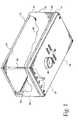
- FIG. 1is a perspective view of a gas panel system including a housing and a gas panel mounting plate;
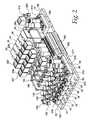
- FIG. 2is a perspective view of the gas panel shown in FIG. 1;
- FIG. 3is a top elevational view of the gas panel shown in FIG. 2;
- FIG. 4is a perspective view of a bottom portion of the gas panel shown in FIG. 2;
- FIG. 5is a perspective view, with portions shown in phantom, of a gas manifold shown in FIG. 2;
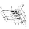
- FIG. 6is an exploded perspective view, with portions shown in phantom, of an outlet gas panel manifold for an alternative embodiment
- FIG. 7is a perspective view of an inlet gas panel manifold for an alternative embodiment
- FIG. 8is a perspective section view of a mass flow controller used with the gas panel embodying the present invention.
- FIG. 9is a view of a bottom portion of a mass flow control base block connected in jumpering configuration with portions of the gas panel system;
- FIG. 10is an exploded perspective view of a bottom block of the mass flow controller showing details of its assembly with a gas panel manifold;
- FIG. 11is a perspective view of a deformable edge-type seal element shown in FIG. 10;
- FIG. 12is an exploded perspective view of a keeper and C-ring seal
- FIG. 13is a perspective view of the keeper shown in FIG. 12 engaging the C-ring seal
- FIG. 14is a sectional view taken between a portion of the mass flow controller and a portion of one of the gas panel manifold showing details of the engagement between the C-ring seal and the manifold;
- FIG. 15is an exploded perspective of a pneumatic control valve showing details of a flange mounting assembly for coupling with a gas manifold;
- FIG. 16is a perspective view of an edge-type seal used in the assembly shown in FIG. 15;
- FIG. 17is an exploded perspective view of a jumper conduit
- FIG. 18is a view, partially in section, and exploded, of details of a connection fitting of the jumper conduit shown in FIG. 17;
- FIG. 19is a perspective view, partially in section, showing details of the mounting of a gas manifold above the as panel support platform;
- FIG. 20is a perspective view of a partially disassembled gas panel stick to show details of some of the connection relations therein;
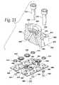
- FIG. 21is an exploded perspective view of a flange or coupling a valve to a gas manifold
- FIG. 22is a section view of the flange shown in FIG. 1;
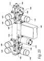
- FIG. 23is a perspective view of an alternative embodiment of an assembly gas manifold
- FIG. 24is a top elevation, with portions in phantom, of the manifold shown in FIG. 23;
- FIG. 25is a side elevation, with portions in phantom, of the manifold shown in FIG. 23;
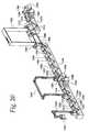
- FIG. 26is a section of a portion of the assembled gas manifold shown in FIG. 23 .
- a gas panel assemblygenerally identified by numeral 10 , is shown therein and includes a gas panel housing 12 having a gas panel 14 positioned between an upper housing half 16 and a lower housing half 18 .
- the gas panel assemblyreceives multiple process gases from a source and provides them to a tool for fabricating a semiconductor wafer.
- the housingis adapted to confine gases which may leak from the gas panel 14 to the immediate vicinity of the gas panel and to carry them away efficiency.
- the gas panelitself has extending therefrom a plurality of posts 20 which contact a top wall 24 of the upper portion of the housing 16 .
- the housingalso includes a pair of end walls 26 and 28 , a back wall 30 and a front wall 32 .
- the bottom housing 18includes a bottom wall 34 having a plurality of inlet apertures 36 formed therein adapted to receive gas flow lines coupled to other portions of the gas panel 14 .
- the apertures 36are sized significantly larger than the diameter of the gas flow lines to also function as sweep air inlets into the housing 12 . Swept air is exhausted through an exhaust plenum 38 which may be coupled to a suitable low pressure or vacuum source.
- a plurality of electrical connections 40is also positioned in the bottom wall 34 to allow wiring to be connected to portions of the gas panel 14 .
- the gas panel 14is shown therein and has a plurality of process gas sticks or process gas assemblies 50 , 52 , 54 , 56 and 58 .
- a nitrogen purge gas assembly 60is also positioned on an aluminum platform 62 .
- the aluminum platform 62has tubing inlet bores 70 , 72 , 74 , 76 , and 78 as well as a purge gas bore 80 formed therein for connection to inlets of each the gas sticks.
- the process gas sticks 50 , 52 , 54 , 56 and 58are substantially identical.
- Each of the sticksincludes an inlet 100 as is shown in the exemplary stick 50 .
- the inlet 100comprising a U-shaped tube having a threaded portion of a VCR fitting 102 connected thereto.
- the U-shaped tube 100is coupled to a tube base 104 which is coupled to an inlet manifold 118 are shown.
- the manifoldalso includes an end wall or face 120 .
- Each of the sticksincludes a plurality of active devices or
- a process gas such as silane or the likeis delivered from a line connected to nut 102 through the U-tube 100 and into the base 104 where it is delivered to the inlet manifold.
- a manual valve 130comprising one of the active devices or gas components and mounted on the base, may be turned to close transmission for the process gas through the manifold.
- the manifoldhas a plurality of bores formed therein, which bores are in communication between the inlet 100 and the valve 130 .
- the gasis then passed to a pneumatic valve 134 which is controllable through a pneumatic stem 136 from a suitable source of pneumatic gas.
- a purge valve 140is connected through a bridging U-tube 150 to a second manifold 152 .
- Elongated rectangular manifold 152includes a pair of sidewalls 160 and 162 , a lateral bottom wall 164 , a lateral top wall 166 , and end walls 168 and 170 .
- the manifoldis substantially unitary and comprising a solid piece defining an inlet station 170 and a plurality of active device stations 172 a - 172 f extending there along, including a mass flow controller station 174 , second mass flow controller station 176 , and an outlet station 180 . It may be appreciated that successive stations are connected by bores drilled into the block or manifold 152 .
- the bendable element 150is connected to the inlet 170 and delivers gas to a bore 190 which is coupled to a second bore 192 providing an inlet tube to first active device station 172 a.
- the first active device station 172 ahas a pressure regulator 200 mounted on it, which receives gas from the bore 192 and delivers gas with reduced pressure back through the bore 194 , which is then delivered to a bore 196 .
- the gasis supplied to second station 172 b having a pressure transducer device 206 positioned thereon.
- the pressure transducer 206has a visual read-out 207 for providing a visual indication or the pressure to a user it also has an electrical signalling connection for sending a pressure signal off panel.
- the flow of gascontinues through a bore 208 , to a bore 210 and delivered to a third station 172 c to which a filter/purifier 212 is mounted.
- the filter/purifierremoves moisture from the gas stream and delivers the dried gas stream back through a bore 213 , to a bore 214 .
- the dried gas supplied through the bore 214 to the active device station 172is delivered to a pressure transducer 220 which then delivers the gas after measuring the pressure to a bore 222 , supplying gas to a bore 224 , which is coupled by an aperture 226 to an inlet of a mass flow controller 228 .
- the mass flow controller 228meters the flow of gas in accordance with electrical signals it receives. It delivers the metered gas output to an aperture 230 which supplies the metered output of the gas to a bore 32 , coupled to supply gas to a bore 234 providing gas at the outlet 180 .
- the outlet 180has connected to it a pneumatic valve 240 which is connected by a bridging connectors through chained pneumatic valves 242 , 244 , 246 and 248 , which selectively allowed gas to flow to an outlet line 250 for delivery off the gas panel.
- purge gassuch as dry nitrogen or argon
- purge gascan be received at the purged gas inlet 270 , supplied by a U-tube 272 to a purge gas rectangular manifold 274 , having laterally extending faces including a manual valve 276 positioned in communication with bores therein to enable or disable purged gas, such as nitrogen from traveling through the remainder of the manifold 274 .
- a pneumatic valve 280couples the gas to a pressure transducer 282 , which then may feed the gas through either an elongated U-tube 284 to other portions of the purged gas manifolding system 60 , including an outlet manifold 286 .
- the pneumatic valvesare controlled by a plurality of pneumatic lines 300 , which are driven from an electrical control block 302 , which receives electrical inputs from a suitable outside source.
- the purge gasis then delivered through the U-tube into the block 286 , where it passes through a pneumatic valve 310 and a pressure regulator 312 , and is delivered to the outlet 250 .
- the valvesmay be cycled in such a manner that purge gas may be flowed both into the inlet valve stack side, including valves 290 through 296 and 140 , and the outlet stack side, valves 240 through 248 , causing purge gas to sweep inwardly from both ends of the manifold 152 , keeping the manifold clean while a repair is taking place.
- an inlet manifoldincludes a first active device site 400 , a second active device site 402 , and a third active device site 404 .
- Each of the sites 400 , 402 and 404includes an outer circumferential ring respectively, 406 , 408 and 410 for engagement with an outer edge type connector.
- the U-tube inletis connected to an aperture 412 to feed gas through a bore 414 to a second bore 416 which delivers the gas to an inlet 420 .
- the gasthen flows through the manual valve 130 and is delivered to an outlet aperture 418 which supplies a gas through a bore 420 to a second slanting bore 422 , coupled with the active site 402 .
- the bore 422is connected to an aperture 424 for supplying gas to the pneumatic valve 134 and the gas exits the pneumatic valve- 134 at an opening 430 which supplies gas to a bore 432 connected to a bore 434 .
- a second pneumatic valvemay be coupled at the site 404 which pneumatic valve is a three-way valve able to receive process gas such as silane or the like from the bore 434 which is delivered to the valve at the aperture 440 .
- the valvewill then transfer the process gas to its outlet aperture 442 , which supplies the gas to a bore 444 and a bore 446 to deliver the gas to a manifold outlet 450 coupled to the jumper 150 .
- purge gasmay be received at the aperture 460 and supplied by a transverse bore 462 to a vertical bore 464 to the valve and thereby supply either backward through the bore 434 or in most practical applications, forward through the aperture 442 for flushing of other parts of the line.
- the transfer bore 462is used for transferring gas across blocks so that nitrogen from the nitrogen manifold 60 may be transferred across all of the inlet blocks via the transverse bores.
- FIG. 6An alternative embodiment of an outlet manifold 500 is shown in FIG. 6 and includes an inlet bore 502 for receiving gas from a mass flow controller, regulated gas flow is then transferred through a slanting bore 504 to a second slanting bore 506 and delivered to an active device site 508 to which a valve is connected.
- the gasis delivered to an aperture 510 for delivery to a valve such as the valve 240 or the like.
- the gasis then delivered downward through a vertical bore 515 to a transverse bore 514 , terminating in a first bore coupling 516 and a second bore coupling 518 .
- Fittings 520 and 522respectively connected to the bore couplings for delivery of gas transversely so that a selected gas may be supplied through the panel through the single outlet 250 .
- a typical pneumatic valvesuch as the pneumatic valve 112
- the valve actuatorhas valve components which communicate through a pneumatic interface fitting 552 , which is coupled by a pneumatic line to the pneumatic manifold.
- the valve 112is connected to a flange 554 , having a rectangular base 556 , and a valve accepting collar 558 .
- a plurality of manifold mounting bolts 560extend through apertures 562 for connection with the gas manifold block.
- the valve 112may be preassembled with seal elements attached to it through the use of a prefabricated keeper 570 which is substantially rectangular and includes a plurality of apertures 572 through which the bolts 560 extend.
- the bolts 560are trapped by nylon split rings 574 which lightly engage the bolts, but hold them in the bores 562 so that after preassembly the bolts will not fall out and the unit can be packaged together.
- a seal ring 580having a ring proper 582 , for effecting sealing engagement between the valve and the manifold, includes a ledge 584 having a plurality of semicircular tabs 586 positioned thereabout.
- the tabs 586engage an edge or shoulder 590 , which defines an aperture 592 and the keeper 570 .
- the keeper 570receives a plurality of small bolts 594 at respective apertures 596 , which are in registration with apertures formed in the bottom of the rectangular base 556 of the flange 554 , which holds the keeper against the bottom of the flange 554 .
- the bolts 594engage threaded and counterbored apertures 595 formed in the flange 554 .
- the threaded bores 595act as a holder or retainer for coupling the keeper 570 , and hence the seal ring 580 to the bottom 556 of the flange 554 prior to assembly with the manifold block.
- the sealing ring 580extends slightly below the keeper 570 but is trapped in registration with an opening 602 in the bottom of the flange and extends slightly below the keeper at an extension portion. At best, the unit may be completely preassembled and may be quickly added to the manifold.
- the flange type baseis exemplary of similar flange type bases used throughout the manifolding system wherein the flange may be preassembled with seal rings held securely by keepers.
- FIGS. 17 through 18Another example of such an arrangement is shown in FIGS. 17 through 18, wherein a typical jumper, such as the jumper 150 , is shown therein.
- the jumper 150includes an inlet block 702 having a stem 704 for connection in gas conducting contact with a tube 706 .
- An elbow 708is welded to the tube 706 and a second elbow 710 carries gas from the elbow 708 to a cross piece tube 712 .
- a first return elbow 714is connected to a second returned elbow 716 to deliver gas to an outlet tube 718 coupled at a tube fitting 720 to a block 722 .
- Each of the blocks 702 and 722includes respective bolts 726 , 728 , 730 and 732 , which extend through the block.
- Bolt 726is held by a plastic split ring 740 within a bore 742 of the block.
- the bolt 728is held by a split ring 744 within a bore 746 of the block 702 .
- a tabbed seal table ring 750is positioned in a ring keeper aperture 752 of a metal keeper 754 .
- the keeper 754has a pair of keeper mounting bolt apertures 756 and 758 , which receive keeper mounting bolts 760 and 762 to hold the keeper and to trap the seal ring 750 in registration with the opening from the tube 704 into the keeper and ultimately into the manifold.
- the bolt 730extends through a bolt aperture 770 .
- the bolt 732extends through a bolt aperture 772 into apertures 774 and 776 of a keeper 780 .
- the boltsare held in light engagement prior to assembly by snap rings 790 and 792 and keeper 780 holds a seal ring 794 in engagement with the bottom of the block via the bolts 800 and 802 , which extend through apertures 804 and 806 of the keeper.
- a valve flange 820includes a flange base 820 to having an upstanding cylindrical flange section for contact with a valve such as a pneumatic valve or the like.
- a first bore 826extends between a gas connection aperture 828 and a second bore 830 extends to a gas connection aperture 832 . Both apertures 828 and 832 terminate bottom ends of the bore.
- the upper end of the bore 826terminates in an aperture 836 .
- the upper end of the bore 830terminates in an aperture 838 .
- the bores 828 and 832are at a bottom portion 832 of the flange bottom 822 .
- a pair of metal keepers 850 and 852are substantially rectangular hold a plurality of edge type seals 854 , 856 and 858 .
- the seal 854is positioned at an opening 855 a of a bore 855 b extending to a bore aperture 855 c.
- the seal 856is positioned at the aperture 828 and the seal 858 is positioned at the aperture 832 .
- the seal 854sits in a sealing receiving aperture 860 of the keeper 850 .
- the seal 856sits in a sealing ring receiving aperture 862 of the keeper 850 .
- Seal ring 858sits in a keeper receiving aperture 864 of keeper 852 , and keeper 864 also includes a spare or extra aperture 866 which may be used in other applications.
- a plurality of keeper holding bolts 880 , 882 and 884extend through respective apertures 890 , 892 and 894 of the keeper 852 and to contact with the flange 822 .
- a plurality of split rings 910 , 912 , 914 and 916contact the threaded fasteners including threaded fasteners 870 and 872 for mounting a flange on the gas panel.
- a plurality of keeper bolts 924 , 926 and 928extends through apertures 930 , 932 and 934 to secure the keeper 850 and the accompanying seal rings 854 and 856 against the bottom of the flange 852 .
- the entire flange assemblyprovides highly localized apertures for connection to a manifold body.
- Each aperturehas associated with it a relatively small seal ring for the prevention of leakage between the respective bores 830 , 826 and 855 b, and the manifold. This allows leaks to be easily detected.
- An exemplary mass flow controller 228is used with the gas panel.
- the mass flow controllerincludes a pair of body blocks 1000 and 1002 , bypass 1004 is mounted in a block 1000 .
- Gasis received is in an inlet block 1006 through a gas aperture 1008 and is delivered through a bore 1010 to a bore 1012 within which the bypass is mounted.
- a portion of the gasflows through a sensor tube 1016 which provides an electrical signal to circuitry 1018 indicative of the rate of flow.
- a control signalis supplied to an electromagnetic valve 1020 , which receives gas through an aperture 1022 of a block 1024 , upon which the valve is mounted. Gas is then released through a bore 1026 to a bore aperture 1028 for delivery to other parts of the gas panel system.
- a simplified version of the mass flow controller 28 with some detail removed for clarity, as may best be seen in FIG. 9,discloses the manner in which the mass flow controller may be connected to a manifolding system having a first gas panel manifold 1030 with active site regions 1032 and 1034 thereon.
- a manifold bore 1036is connected to the inlet block bore 1010 .
- the outlet bore 1026is connected to a manifold bore 1042 in a second one-piece gas panel manifold 1040 .
- a keeper 1050as shown in FIGS. 10 and 11, having a seal ring 1052 mounted in a keeper aperture 1054 , is positioned at the aperture 1034 ; which is the inlet to the mass flow controller.
- a keeper 1060having a seal ring 1062 , positioned in a bore 1064 , is mounted on the manifold 1040 , and couples the outlet aperture 1028 of the control block 1024 to the manifold 1040 .
- the controlleris mounted by a pair of bolts 1070 and 1072 to the manifolds 1030 and 1040 .
- edge seal 1050includes a plurality of semi-circular tabs 1080 extending thereabout for supporting the seal in the keeper prior to assembly.
- a C-ring type seal 1098may be used between the inlet block 1010 of the mass flow controller and the manifold block 1030 .
- the C-ring seal 1098includes a substantially toroidal split ring 1100 having a helically wound spring 1102 positioned therein for supporting the split ring 1100 .
- a keeper 1104holds the split ring assembly 1098 in contact with itself.
- the keeper 1104includes a first arcuate section 1116 having a split ring tab 1118 formed thereon for engagement with an open slot 1120 in the split ring.
- the second wave-like arcuate section 1122has a tab 1124 for engaging the split ring seal 1098 .
- a shoulder section 1130 , and the shoulder section 1132also engage the opening 1120 to the split ring 1098 .
- the keeperfunctions as the other keepers do in the system. It holds the split ring 1098 in registration with one of the apertures of the mass flow controller, when the mass flow controller is being attached to a manifold.
- an inlet manifold 110is mounted on a standoff 1200 , which is identical to other standoffs 1200 , extending through the platform 62 .
- the standoff 1200includes a bolt portion 1204 which is in threaded engagement with a sleeve 1206 at a bottom bore 1208 .
- the sleeve. 1206includes an upper bore 1210 which receives a second or mounting bolt 1212 in threaded engagement therewith.
- the mounting boltextending through a mounting bracket 1214 .
- the height at which the upper wall 51 of the inlet manifold 51 may be supportedmay be adjusted and may be aligned with other upper walls to provide a substantially planar, multiple wall surface for the attachment of bridging connections between successive gas sticks.
- a slight amount of playis allowed between a bore 1226 within which the sleeve is located and the sleeve itself, to allow for slight lateral transitions or movement of the manifolds with respect to one another to allow easy cross connections between the manifolds.
- a gas manifold assembly 1300in another embodiment, as may best be seen in FIG. 20, includes a VCR inlet 1302 , which receives gas and sends gas through a jumper 1304 to a first gas manifold 1306 , having a laterally extending upper wall 1308 , having a plurality of active sites 1310 , 1312 and 1314 , positioned thereon.
- the active sitesare unpopulated. But for instance, site 1310 would likely have a manual valve and sites 1312 and 1314 would likely have pneumatic valves connected to them.
- the position between the sitesare inlet and outlet bores 1324 and 1326 , pair of bores 1328 and 1330 , extending between site 1310 and active site 1312 and the like.
- a cross connect 1334which receives a gas, such as a-purged gas or nitrogen at a bore 1336 , passes a gas to a second bore 1338 , and then into a bore 1340 , which is connected to the active site 1312 , which is able to route gas to a second jumper 1344 , coupled to a second gas manifold 1346 .
- the second gas manifold 1346includes an upper wall 1348 , having a plurality of active sites 1350 , 1352 , 1354 and 1356 coupled by pair of v-connected bores which are connected to a mass flow controller 1362 of which only the blocks and the housing are shown.
- the mass flow controllerhaving an inlet block 1364 connected to receive gas, a first body block 1366 having a bypass 1368 therein, and a valve or outlet block 1370 connected to an outlet manifold 1372 .
- the outlet manifold 1372receives regulated gas from the mass flow controller at a bore 1374 , and passes the gas to an active site 1376 which includes a valve or the like.
- Another manifolding system 1400is specifically adapted to be used in a moisture sampling system for determining the levels of trace amounts of moisture carried in a gas or other vapor stream.
- gasis flowed into the inlet 1408 and is received at a port 1420 and is delivered to a first valve station 1422 , having a first pneumatic valve 1424 mounted thereon.
- the gasmay then be supplied to a moisture scrubber station through the valve 1424 .
- the scrubber station 1426has a scrubber connector 1428 connected thereto with a pair or tubing stubs 1430 and 1432 for connection to a moisture scrubber.
- Also connected to the inletis a pneumatic valve 1442 , connected at a pneumatic valve station 1444 to receive gas therefrom.
- the scrubber station 1426is connected to a third valve station 1450 having a pneumatic valve 1452 connected thereto.
- the pneumatic valve 1452is connectable to send gas from the inlet to a mass flow controller 1460 mounted at a controller station 1462 .
- valves 1424 and 1452are closed.
- Valve 1442is opened, and the gas to be measured is flowed directly into the mass flow controller.
- Downstream of the mass flow controlleris a permeation site 1468 having a permeation cell 1470 connected thereto for supplying a trace amount of moisture to the gas, after it flows out of the mass flow controller.
- the gasis then delivered to a first pneumatic valve 1486 and a second pneumatic valve 1488 at valve sites 1490 and 1492 , respectively.
- a trace moisture sensor 1496is connected to receive gas from the valve 1486 and delivers the gas to a valve 1498 .
- gas from the permeation cell 1470may be delivered to the valve 1488 for later downstream delivery to other locations.
- An outlet 1500is provided from valve 1498 and an outlet is provided from the valve 1488 .
- Zero mode operationwhen the scrubber is connected in series with the mass flow controller, causes the valves 1486 , 1488 , and 1498 to be opened allowing some moisture carrying gas to enter the sensor cell 1496 and other moisture carrying gas to be exhausted out through the valve 1488 .
- valves 1486 and 1498are open, causing all of the gas to flow through the sensor 1496 and out the valve V 6 at a low flow rate.
- valves 1486 , 1488 and 1498are all open.
Landscapes
- Chemical & Material Sciences (AREA)
- Engineering & Computer Science (AREA)
- Mechanical Engineering (AREA)
- Organic Chemistry (AREA)
- Metallurgy (AREA)
- Materials Engineering (AREA)
- Chemical Kinetics & Catalysis (AREA)
- General Chemical & Material Sciences (AREA)
- Physics & Mathematics (AREA)
- Manufacturing & Machinery (AREA)
- Power Engineering (AREA)
- Microelectronics & Electronic Packaging (AREA)
- Computer Hardware Design (AREA)
- General Physics & Mathematics (AREA)
- Condensed Matter Physics & Semiconductors (AREA)
- Plasma & Fusion (AREA)
- General Engineering & Computer Science (AREA)
- Analytical Chemistry (AREA)
- Valve Housings (AREA)
- Chemical Vapour Deposition (AREA)
- Feeding, Discharge, Calcimining, Fusing, And Gas-Generation Devices (AREA)
- Multiple-Way Valves (AREA)
- Details Of Valves (AREA)
- Filling Or Discharging Of Gas Storage Vessels (AREA)
Abstract
Description
Claims (6)
Priority Applications (2)
| Application Number | Priority Date | Filing Date | Title |
|---|---|---|---|
| US09/732,434US6474700B2 (en) | 1996-10-30 | 2000-12-07 | Gas panel |
| US09/939,487US6435215B1 (en) | 1996-10-30 | 2001-08-23 | Gas panel |
Applications Claiming Priority (3)
| Application Number | Priority Date | Filing Date | Title |
|---|---|---|---|
| US08/739,936US5992463A (en) | 1996-10-30 | 1996-10-30 | Gas panel |
| US09/371,655US6189570B1 (en) | 1996-10-30 | 1999-08-10 | Gas panel |
| US09/732,434US6474700B2 (en) | 1996-10-30 | 2000-12-07 | Gas panel |
Related Parent Applications (1)
| Application Number | Title | Priority Date | Filing Date |
|---|---|---|---|
| US09/371,655DivisionUS6189570B1 (en) | 1996-10-30 | 1999-08-10 | Gas panel |
Related Child Applications (1)
| Application Number | Title | Priority Date | Filing Date |
|---|---|---|---|
| US09/939,487DivisionUS6435215B1 (en) | 1996-10-30 | 2001-08-23 | Gas panel |
Publications (2)
| Publication Number | Publication Date |
|---|---|
| US20020020353A1 US20020020353A1 (en) | 2002-02-21 |
| US6474700B2true US6474700B2 (en) | 2002-11-05 |
Family
ID=24974393
Family Applications (7)
| Application Number | Title | Priority Date | Filing Date |
|---|---|---|---|
| US08/739,936Expired - LifetimeUS5992463A (en) | 1996-10-30 | 1996-10-30 | Gas panel |
| US09/371,408Expired - Fee RelatedUS6192938B1 (en) | 1996-10-30 | 1999-08-10 | Gas panel |
| US09/371,655Expired - Fee RelatedUS6189570B1 (en) | 1996-10-30 | 1999-08-10 | Gas panel |
| US09/371,659Expired - LifetimeUS6142539A (en) | 1996-10-30 | 1999-08-10 | Gas panel |
| US09/732,435AbandonedUS20010013371A1 (en) | 1996-10-30 | 2000-12-07 | Gas panel |
| US09/732,434Expired - LifetimeUS6474700B2 (en) | 1996-10-30 | 2000-12-07 | Gas panel |
| US09/939,487Expired - LifetimeUS6435215B1 (en) | 1996-10-30 | 2001-08-23 | Gas panel |
Family Applications Before (5)
| Application Number | Title | Priority Date | Filing Date |
|---|---|---|---|
| US08/739,936Expired - LifetimeUS5992463A (en) | 1996-10-30 | 1996-10-30 | Gas panel |
| US09/371,408Expired - Fee RelatedUS6192938B1 (en) | 1996-10-30 | 1999-08-10 | Gas panel |
| US09/371,655Expired - Fee RelatedUS6189570B1 (en) | 1996-10-30 | 1999-08-10 | Gas panel |
| US09/371,659Expired - LifetimeUS6142539A (en) | 1996-10-30 | 1999-08-10 | Gas panel |
| US09/732,435AbandonedUS20010013371A1 (en) | 1996-10-30 | 2000-12-07 | Gas panel |
Family Applications After (1)
| Application Number | Title | Priority Date | Filing Date |
|---|---|---|---|
| US09/939,487Expired - LifetimeUS6435215B1 (en) | 1996-10-30 | 2001-08-23 | Gas panel |
Country Status (8)
| Country | Link |
|---|---|
| US (7) | US5992463A (en) |
| EP (1) | EP0938634B1 (en) |
| JP (1) | JP2001503840A (en) |
| KR (1) | KR100633190B1 (en) |
| AU (1) | AU5097198A (en) |
| DE (1) | DE69734997T2 (en) |
| TW (1) | TW406306B (en) |
| WO (1) | WO1998021744A2 (en) |
Cited By (31)
| Publication number | Priority date | Publication date | Assignee | Title |
|---|---|---|---|---|
| US20040129324A1 (en)* | 2002-08-27 | 2004-07-08 | Celerity Group, Inc. | Modular substrate gas panel having manifold connections in a common plane |
| US20040173270A1 (en)* | 2003-03-03 | 2004-09-09 | Harris James M. | Fluid delivery system and mounting panel therefor |
| US20050028878A1 (en)* | 2003-08-07 | 2005-02-10 | Reid Kenneth Edward | Modular component connector substrate assembly system |
| US20050224121A1 (en)* | 2004-04-13 | 2005-10-13 | Milburn Matthew L | Gas-panel assembly |
| US20050284529A1 (en)* | 2004-06-25 | 2005-12-29 | Toshiaki Iwabuchi | Integrated gas control device |
| US20060272720A1 (en)* | 2005-06-02 | 2006-12-07 | Milburn Matthew L | Gas-panel assembly |
| US20060272721A1 (en)* | 2005-06-02 | 2006-12-07 | Milburn Matthew L | Gas-panel assembly |
| US20070204912A1 (en)* | 2006-03-01 | 2007-09-06 | Asahi Organic Chemicals Industry Co., Ltd. | Fluid mixing system |
| US20070224708A1 (en)* | 2006-03-21 | 2007-09-27 | Sowmya Krishnan | Mass pulse sensor and process-gas system and method |
| US7279398B2 (en) | 2003-09-17 | 2007-10-09 | Micron Technology, Inc. | Microfeature workpiece processing apparatus and methods for controlling deposition of materials on microfeature workpieces |
| US20080009977A1 (en)* | 2006-07-10 | 2008-01-10 | Ultra Clean Holdings | Apparatus and Method for Monitoring a Chemical-Supply System |
| US7335396B2 (en) | 2003-04-24 | 2008-02-26 | Micron Technology, Inc. | Methods for controlling mass flow rates and pressures in passageways coupled to reaction chambers and systems for depositing material onto microfeature workpieces in reaction chambers |
| US7387685B2 (en) | 2002-07-08 | 2008-06-17 | Micron Technology, Inc. | Apparatus and method for depositing materials onto microelectronic workpieces |
| US20080302426A1 (en)* | 2007-06-06 | 2008-12-11 | Greg Patrick Mulligan | System and method of securing removable components for distribution of fluids |
| US7481887B2 (en) | 2002-05-24 | 2009-01-27 | Micron Technology, Inc. | Apparatus for controlling gas pulsing in processes for depositing materials onto micro-device workpieces |
| US20090078324A1 (en)* | 2007-09-21 | 2009-03-26 | Ultra Clean Technology, Inc. | Gas-panel system |
| US20090114295A1 (en)* | 2007-11-06 | 2009-05-07 | Ultra Clean Holdings, Inc. | Gas-panel assembly |
| US20090308799A1 (en)* | 2005-04-28 | 2009-12-17 | Keuk Rae Cho | Water filter housing cap |
| US7699932B2 (en) | 2004-06-02 | 2010-04-20 | Micron Technology, Inc. | Reactors, systems and methods for depositing thin films onto microfeature workpieces |
| US20100112814A1 (en)* | 2006-09-06 | 2010-05-06 | Sowmya Krishnan | Pre-certified process chamber and method |
| US7771537B2 (en) | 2003-12-10 | 2010-08-10 | Micron Technology, Inc. | Methods and systems for controlling temperature during microfeature workpiece processing, E.G. CVD deposition |
| US20110030815A1 (en)* | 2006-03-01 | 2011-02-10 | Asahi Organic Chemicals Industry Co., Ltd. | Fluid mixing system |
| US8384192B2 (en) | 2004-01-28 | 2013-02-26 | Micron Technology, Inc. | Methods for forming small-scale capacitor structures |
| US20140252724A1 (en)* | 2013-03-08 | 2014-09-11 | Denso Corporation | Self-retaining gasket |
| US20140252723A1 (en)* | 2013-03-08 | 2014-09-11 | Denso Corporation | Self-retaining gasket and fastener retainer |
| US8950433B2 (en) | 2011-05-02 | 2015-02-10 | Advantage Group International Inc. | Manifold system for gas and fluid delivery |
| US20170322568A1 (en)* | 2016-05-09 | 2017-11-09 | Applied Materials, Inc. | Gas panel apparatus and method for reducing exhaust requirements |
| US9869409B2 (en) | 2013-01-15 | 2018-01-16 | Vistadeltek, Llc | Gasket retainer for surface mount fluid component |
| US10400332B2 (en)* | 2017-03-14 | 2019-09-03 | Eastman Kodak Company | Deposition system with interlocking deposition heads |
| US10502321B2 (en) | 2014-01-14 | 2019-12-10 | Compart Systems Pte, Ltd. | Gasket retainer for surface mount fluid component |
| US10731768B2 (en) | 2016-10-12 | 2020-08-04 | Ecolab Usa Inc. | Systems and methods for manifold valves |
Families Citing this family (110)
| Publication number | Priority date | Publication date | Assignee | Title |
|---|---|---|---|---|
| US5992463A (en) | 1996-10-30 | 1999-11-30 | Unit Instruments, Inc. | Gas panel |
| US6394138B1 (en) | 1996-10-30 | 2002-05-28 | Unit Instruments, Inc. | Manifold system of removable components for distribution of fluids |
| US6293310B1 (en) | 1996-10-30 | 2001-09-25 | Unit Instruments, Inc. | Gas panel |
| US6302141B1 (en) | 1996-12-03 | 2001-10-16 | Insync Systems, Inc. | Building blocks for integrated gas panel |
| JP3997338B2 (en)* | 1997-02-14 | 2007-10-24 | 忠弘 大見 | Fluid control device |
| JP3737869B2 (en)* | 1997-05-13 | 2006-01-25 | シーケーディ株式会社 | Process gas supply unit |
| JP4378553B2 (en)* | 1997-10-13 | 2009-12-09 | 忠弘 大見 | Fluid control device |
| JP3780096B2 (en)* | 1998-04-27 | 2006-05-31 | シーケーディ株式会社 | Process gas supply unit |
| JP2000145979A (en)* | 1998-11-16 | 2000-05-26 | Fujikin Inc | Lower stage member fixing device and fluid controller equipped with the same |
| WO2000031462A1 (en) | 1998-11-20 | 2000-06-02 | Mykrolis Corporation | System and method for integrating gas components |
| US6189238B1 (en)* | 1998-11-30 | 2001-02-20 | Lucent Technologies Inc. | Portable purge system for transporting materials |
| US6345642B1 (en)* | 1999-02-19 | 2002-02-12 | Applied Materials, Inc. | Method and apparatus for removing processing liquid from a processing liquid path |
| FR2794844B1 (en)* | 1999-06-08 | 2001-08-03 | Air Liquide | METHOD AND DEVICE FOR GASTING A CORROSIVE GAS DISTRIBUTION LINE |
| US6186177B1 (en)* | 1999-06-23 | 2001-02-13 | Mks Instruments, Inc. | Integrated gas delivery system |
| US6729353B2 (en) | 1999-09-01 | 2004-05-04 | Asml Us, Inc. | Modular fluid delivery apparatus |
| USD435087S (en)* | 1999-09-30 | 2000-12-12 | Griffin Llc | Valve seal |
| US6283155B1 (en)* | 1999-12-06 | 2001-09-04 | Insync Systems, Inc. | System of modular substrates for enabling the distribution of process fluids through removable components |
| DE10013192B4 (en)* | 2000-03-17 | 2004-05-06 | Festo Ag & Co. | valve assembly |
| JP2001269567A (en)* | 2000-03-24 | 2001-10-02 | Bioneer Corp | Multichannel quantitative control valve device |
| US6357760B1 (en) | 2000-05-19 | 2002-03-19 | Michael Doyle | Ring seal |
| JP2002089798A (en)* | 2000-09-11 | 2002-03-27 | Ulvac Japan Ltd | Fluid control device and gas treatment equipment using it |
| US6349744B1 (en) | 2000-10-13 | 2002-02-26 | Mks Instruments, Inc. | Manifold for modular gas box system |
| TW524944B (en) | 2001-05-16 | 2003-03-21 | Unit Instr Inc | Fluid flow system |
| US7150475B2 (en)* | 2001-07-13 | 2006-12-19 | Talon Innovations, Inc. | Shear-resistant modular fluidic blocks |
| US6670071B2 (en)* | 2002-01-15 | 2003-12-30 | Quallion Llc | Electric storage battery construction and method of manufacture |
| US7039999B2 (en)* | 2002-04-25 | 2006-05-09 | Tarr Adam L | Method for installation of semiconductor fabrication tools |
| US6955725B2 (en)* | 2002-08-15 | 2005-10-18 | Micron Technology, Inc. | Reactors with isolated gas connectors and methods for depositing materials onto micro-device workpieces |
| CN100339629C (en)* | 2002-10-21 | 2007-09-26 | 喜开理株式会社 | Integrated gas valve |
| US20040140211A1 (en)* | 2003-01-21 | 2004-07-22 | Broy Stephen H. | Modular interface and coupling system and method |
| US20050005981A1 (en)* | 2003-03-26 | 2005-01-13 | Paul Eidsmore | Modular fluid components and assembly |
| US7344755B2 (en)* | 2003-08-21 | 2008-03-18 | Micron Technology, Inc. | Methods and apparatus for processing microfeature workpieces; methods for conditioning ALD reaction chambers |
| US7235138B2 (en) | 2003-08-21 | 2007-06-26 | Micron Technology, Inc. | Microfeature workpiece processing apparatus and methods for batch deposition of materials on microfeature workpieces |
| US7422635B2 (en) | 2003-08-28 | 2008-09-09 | Micron Technology, Inc. | Methods and apparatus for processing microfeature workpieces, e.g., for depositing materials on microfeature workpieces |
| US7282239B2 (en)* | 2003-09-18 | 2007-10-16 | Micron Technology, Inc. | Systems and methods for depositing material onto microfeature workpieces in reaction chambers |
| US7323231B2 (en)* | 2003-10-09 | 2008-01-29 | Micron Technology, Inc. | Apparatus and methods for plasma vapor deposition processes |
| US7581511B2 (en)* | 2003-10-10 | 2009-09-01 | Micron Technology, Inc. | Apparatus and methods for manufacturing microfeatures on workpieces using plasma vapor processes |
| US7647886B2 (en) | 2003-10-15 | 2010-01-19 | Micron Technology, Inc. | Systems for depositing material onto workpieces in reaction chambers and methods for removing byproducts from reaction chambers |
| JP2007511052A (en)* | 2003-11-07 | 2007-04-26 | セレリティ・インコーポレイテッド | Surface mount heater |
| US7044147B2 (en)* | 2004-03-15 | 2006-05-16 | Atmel Corporation | System, apparatus and method for contaminant reduction in semiconductor device fabrication equipment components |
| US7584942B2 (en) | 2004-03-31 | 2009-09-08 | Micron Technology, Inc. | Ampoules for producing a reaction gas and systems for depositing materials onto microfeature workpieces in reaction chambers |
| US20050249873A1 (en)* | 2004-05-05 | 2005-11-10 | Demetrius Sarigiannis | Apparatuses and methods for producing chemically reactive vapors used in manufacturing microelectronic devices |
| US8133554B2 (en) | 2004-05-06 | 2012-03-13 | Micron Technology, Inc. | Methods for depositing material onto microfeature workpieces in reaction chambers and systems for depositing materials onto microfeature workpieces |
| WO2006020424A2 (en)* | 2004-08-02 | 2006-02-23 | Veeco Instruments Inc. | Multi-gas distribution injector for chemical vapor deposition reactors |
| JP4555052B2 (en)* | 2004-11-04 | 2010-09-29 | シーケーディ株式会社 | Gas supply integrated unit |
| EP1836422A2 (en)* | 2004-12-24 | 2007-09-26 | Picanol N.V. | Throttle valve for weaving looms |
| US7628168B2 (en) | 2005-06-10 | 2009-12-08 | Lam Research Corporation | Optimized activation prevention assembly for a gas delivery system and methods therefor |
| KR100706251B1 (en)* | 2005-07-14 | 2007-04-12 | 삼성전자주식회사 | Semiconductor manufacturing apparatus and refrigerant circulation method |
| JP2007034667A (en)* | 2005-07-27 | 2007-02-08 | Surpass Kogyo Kk | Flow controller, and regulator unit and valve unit used therefor |
| JP2007102754A (en)* | 2005-09-09 | 2007-04-19 | Advance Denki Kogyo Kk | Flow controller |
| US7651585B2 (en)* | 2005-09-26 | 2010-01-26 | Lam Research Corporation | Apparatus for the removal of an edge polymer from a substrate and methods therefor |
| US20070068623A1 (en)* | 2005-09-27 | 2007-03-29 | Yunsang Kim | Apparatus for the removal of a set of byproducts from a substrate edge and methods therefor |
| US7691278B2 (en)* | 2005-09-27 | 2010-04-06 | Lam Research Corporation | Apparatus for the removal of a fluorinated polymer from a substrate and methods therefor |
| US7662253B2 (en)* | 2005-09-27 | 2010-02-16 | Lam Research Corporation | Apparatus for the removal of a metal oxide from a substrate and methods therefor |
| US7909960B2 (en)* | 2005-09-27 | 2011-03-22 | Lam Research Corporation | Apparatus and methods to remove films on bevel edge and backside of wafer |
| US7664607B2 (en) | 2005-10-04 | 2010-02-16 | Teledyne Technologies Incorporated | Pre-calibrated gas sensor |
| WO2007052853A1 (en)* | 2005-11-01 | 2007-05-10 | Sun Young Lee | Gas guide apparatus |
| US7439558B2 (en) | 2005-11-04 | 2008-10-21 | Atmel Corporation | Method and system for controlled oxygen incorporation in compound semiconductor films for device performance enhancement |
| US20070102729A1 (en)* | 2005-11-04 | 2007-05-10 | Enicks Darwin G | Method and system for providing a heterojunction bipolar transistor having SiGe extensions |
| US7651919B2 (en)* | 2005-11-04 | 2010-01-26 | Atmel Corporation | Bandgap and recombination engineered emitter layers for SiGe HBT performance optimization |
| US7300849B2 (en)* | 2005-11-04 | 2007-11-27 | Atmel Corporation | Bandgap engineered mono-crystalline silicon cap layers for SiGe HBT performance enhancement |
| US7575616B2 (en)* | 2006-02-10 | 2009-08-18 | Entegris, Inc. | Low-profile surface mount filter |
| JP5096696B2 (en)* | 2006-03-02 | 2012-12-12 | サーパス工業株式会社 | Fluid equipment unit structure |
| DE202006004749U1 (en)* | 2006-03-24 | 2006-06-29 | Bürkert Werke GmbH & Co. KG | Device and valve combination for flow reversal of flowing media |
| FR2899302B1 (en)* | 2006-03-28 | 2011-06-10 | Eif | FLUID DISPENSING ASSEMBLY AND CORRESPONDING USE THEREOF. |
| JP2007327542A (en)* | 2006-06-07 | 2007-12-20 | Surpass Kogyo Kk | Fluid apparatus unit structure |
| JP5037510B2 (en) | 2006-08-23 | 2012-09-26 | 株式会社堀場エステック | Integrated gas panel device |
| KR100773756B1 (en)* | 2006-09-13 | 2007-11-09 | 주식회사 아이피에스 | Gas flow block |
| FR2907037B1 (en)* | 2006-10-13 | 2009-01-09 | Sidel Participations | DEPOSITION INSTALLATION, USING MICROWAVE PLASMA, INTERNAL BARRIER COATING IN THERMOPLASTIC CONTAINERS |
| US7798388B2 (en)* | 2007-05-31 | 2010-09-21 | Applied Materials, Inc. | Method of diffusion bonding a fluid flow apparatus |
| US20080296354A1 (en)* | 2007-05-31 | 2008-12-04 | Mark Crockett | Stainless steel or stainless steel alloy for diffusion bonding |
| US7784496B2 (en)* | 2007-06-11 | 2010-08-31 | Lam Research Corporation | Triple valve inlet assembly |
| US7806143B2 (en)* | 2007-06-11 | 2010-10-05 | Lam Research Corporation | Flexible manifold for integrated gas system gas panels |
| US7784497B2 (en)* | 2007-07-12 | 2010-08-31 | Eriksson Mark L | MSM component and associated gas panel assembly |
| US8307854B1 (en) | 2009-05-14 | 2012-11-13 | Vistadeltek, Inc. | Fluid delivery substrates for building removable standard fluid delivery sticks |
| US20110031704A1 (en)* | 2009-05-15 | 2011-02-10 | Lehr Brian C | Segmented Gaskets |
| TWI534922B (en) | 2009-06-10 | 2016-05-21 | 威士塔戴爾泰克有限責任公司 | Extreme flow rate and/or high temperature fluid delivery substrates |
| JP2012097879A (en)* | 2010-11-05 | 2012-05-24 | Surpass Kogyo Kk | Fluidic device unit structure |
| US20120298238A1 (en)* | 2011-05-25 | 2012-11-29 | Parker-Hannifin Corporation | Modular fluidic mixing system |
| US9188990B2 (en)* | 2011-10-05 | 2015-11-17 | Horiba Stec, Co., Ltd. | Fluid mechanism, support member constituting fluid mechanism and fluid control system |
| JP5868219B2 (en)* | 2012-02-29 | 2016-02-24 | 株式会社フジキン | Fluid control device |
| US8851113B2 (en)* | 2012-03-27 | 2014-10-07 | Lam Research Coporation | Shared gas panels in plasma processing systems |
| US9091397B2 (en) | 2012-03-27 | 2015-07-28 | Lam Research Corporation | Shared gas panels in plasma processing chambers employing multi-zone gas feeds |
| JP5887188B2 (en)* | 2012-04-12 | 2016-03-16 | 株式会社堀場エステック | Fluid control equipment |
| JP6012247B2 (en)* | 2012-04-27 | 2016-10-25 | 株式会社フジキン | Fluid control device |
| CN104061973B (en)* | 2013-03-18 | 2017-07-25 | 北京堀场汇博隆精密仪器有限公司 | Flowmeter |
| US9335768B2 (en)* | 2013-09-12 | 2016-05-10 | Lam Research Corporation | Cluster mass flow devices and multi-line mass flow devices incorporating the same |
| TWI646278B (en)* | 2013-12-05 | 2019-01-01 | Ckd股份有限公司 | Piping joint, fluid supply control device, and piping connection structure |
| EP3835629A1 (en) | 2014-04-17 | 2021-06-16 | Compart Systems Pte. Ltd. | Gasket with ultra-sealing effect for joining high purity fluid pathways |
| TWI679364B (en) | 2014-06-13 | 2019-12-11 | 日商堀場Stec股份有限公司 | High conductance valve for fluids and vapors |
| DE102014114227A1 (en)* | 2014-09-30 | 2016-03-31 | Elringklinger Ag | Connecting device and component composite |
| EP3218626B1 (en)* | 2014-11-15 | 2023-11-15 | Versum Materials US, LLC | Improved valve block having minimal deadleg |
| JP6054470B2 (en) | 2015-05-26 | 2016-12-27 | 株式会社日本製鋼所 | Atomic layer growth equipment |
| JP6054471B2 (en) | 2015-05-26 | 2016-12-27 | 株式会社日本製鋼所 | Atomic layer growth apparatus and exhaust layer of atomic layer growth apparatus |
| JP5990626B1 (en)* | 2015-05-26 | 2016-09-14 | 株式会社日本製鋼所 | Atomic layer growth equipment |
| DE102017002471A1 (en)* | 2017-03-10 | 2018-09-13 | Hydac Systems & Services Gmbh | control device |
| US10364897B2 (en) | 2017-06-05 | 2019-07-30 | Vistadeltek, Llc | Control plate for a high conductance valve |
| CN110709633B (en) | 2017-06-05 | 2022-04-22 | 威斯塔德尔特有限责任公司 | Control Board for High Conductivity Valves |
| US10458553B1 (en) | 2017-06-05 | 2019-10-29 | Vistadeltek, Llc | Control plate for a high conductive valve |
| US11248708B2 (en) | 2017-06-05 | 2022-02-15 | Illinois Tool Works Inc. | Control plate for a high conductance valve |
| KR102607020B1 (en)* | 2017-09-19 | 2023-11-29 | 가부시키가이샤 호리바 에스텍 | Concentration control apparatus and material gas supply system |
| CN119532484A (en)* | 2018-07-17 | 2025-02-28 | 肯发系统有限公司 | Installation structure of flow substrate |
| KR20250057125A (en) | 2019-04-15 | 2025-04-28 | 램 리써치 코포레이션 | Modular-component system for gas delivery |
| JP7393788B2 (en)* | 2020-01-08 | 2023-12-07 | アドバンス電気工業株式会社 | valve structure |
| CN116250069A (en)* | 2020-09-28 | 2023-06-09 | 朗姆研究公司 | Compact modular gas distribution duct and heating system for multi-station deposition module |
| JP7687791B2 (en)* | 2021-03-15 | 2025-06-03 | 東京エレクトロン株式会社 | Temperature control unit and processing device |
| US20220336235A1 (en)* | 2021-04-16 | 2022-10-20 | Taiwan Semiconductor Manufacturing Company Ltd. | Valve box module, semiconductor device manufacturing system and method for manufacturing semiconductor device |
| JP2025506812A (en)* | 2022-02-23 | 2025-03-13 | アイコール・システムズ・インク | Fluid Delivery Module |
| TW202426686A (en)* | 2022-08-19 | 2024-07-01 | 美商蘭姆研究公司 | Dual-channel monoblock gas manifold |
| CN116447355A (en)* | 2023-03-16 | 2023-07-18 | 苏州天一信德环保科技有限公司 | An auxiliary valve group of a nitrogen oxide analyzer |
| JP2024158856A (en)* | 2023-04-28 | 2024-11-08 | 株式会社堀場エステック | FLUID CONTROL VALVE, FLUID CONTROL DEVICE, AND MATERIAL SUPPLY SYSTEM |
Citations (63)
| Publication number | Priority date | Publication date | Assignee | Title |
|---|---|---|---|---|
| US3025878A (en) | 1959-06-02 | 1962-03-20 | Robert C Hupp | Mounting panel for fluid control components |
| US3234964A (en) | 1963-09-23 | 1966-02-15 | Cleere B Tinsley | Manifold |
| US3384115A (en) | 1964-09-29 | 1968-05-21 | Zd Y Prumyslove Automatisace | Pneumatic logic system on the block principle |
| US3476214A (en) | 1968-02-01 | 1969-11-04 | Mccord Corp | Divisional lubricant feeder with bypass means |
| US3486519A (en) | 1967-12-26 | 1969-12-30 | Westinghouse Air Brake Co | Panel block assembly |
| US3509904A (en) | 1967-12-26 | 1970-05-05 | Westinghouse Air Brake Co | Panel block assembly |
| FR2250907A1 (en) | 1973-11-09 | 1975-06-06 | Bouteille Daniel | Assembly baseplates for pneumatic or hydraulic distributors - tongue and groove are standard modules which connect with into rigid block |
| US3915194A (en) | 1973-01-18 | 1975-10-28 | Abex Corp | Conduit column assembly for hydraulic valves |
| US3934605A (en) | 1973-07-03 | 1976-01-27 | Societe Legris France S.A. | Modular distributor box for fluids |
| FR2307151A1 (en) | 1975-04-07 | 1976-11-05 | Crouzet Sa | Module for pneumatic control system - uses standard base with surface connections and inserts lanking off unwanted passages |
| US3993091A (en) | 1975-10-06 | 1976-11-23 | General Gas Light Company | Manifold and valve system |
| US4008736A (en) | 1974-03-21 | 1977-02-22 | Wittmann Liebold Brigitte | Valve arrangement for distributing fluids |
| US4080752A (en) | 1975-05-01 | 1978-03-28 | Burge David A | Toy blocks with conduits and fluid seal means |
| US4082324A (en) | 1976-10-04 | 1978-04-04 | Obrecht Robert E | Connection arrangement for manifold blocks |
| US4093329A (en) | 1977-03-22 | 1978-06-06 | Robertshaw Controls Company | Manifolding means and system for electrical and/or pneumatic control devices and methods |
| US4168724A (en) | 1976-10-27 | 1979-09-25 | Max-Planck-Gesellschaft Zur Forderung Der Wissenschaften, E.V. | Valve arrangement for distributing fluids |
| US4181141A (en) | 1977-02-05 | 1980-01-01 | Manfred Rudle | Pneumatic circuit arrangement |
| US4247133A (en) | 1978-12-06 | 1981-01-27 | Wabco Steuerungstechnik Gmbh & Co. | Device with mounting plates for a valve battery |
| US4304120A (en) | 1980-03-21 | 1981-12-08 | Myers Tommy E | Automatic gas measurement and analysis for a test cell |
| US4352532A (en) | 1980-09-15 | 1982-10-05 | Robertshaw Controls Company | Manifolding means for electrical and/or pneumatic control units and parts and methods therefor |
| US4524807A (en) | 1982-05-21 | 1985-06-25 | Humphrey Products Company | Snap-together modular manifold construction |
| US4815280A (en) | 1986-05-27 | 1989-03-28 | Stec Inc. | Thermal flow meter |
| US4815496A (en) | 1986-12-29 | 1989-03-28 | Smc Corporation | Power feeder for solenoid valves |
| US4921072A (en) | 1987-10-19 | 1990-05-01 | Dropsa S.P.A. | Modular progressive hydraulic distributor for lubrication systems |
| WO1990012239A1 (en) | 1989-04-13 | 1990-10-18 | Unit Instruments, Inc. | Sealing means for fluid handling system |
| US4984460A (en) | 1987-12-08 | 1991-01-15 | Lintec Co., Ltd. | Mass flowmeter |
| JPH0435835A (en) | 1990-05-30 | 1992-02-06 | Fanuc Ltd | Stage piled type workfeding device |
| US5141021A (en) | 1991-09-06 | 1992-08-25 | Stec Inc. | Mass flow meter and mass flow controller |
| US5178191A (en) | 1990-09-05 | 1993-01-12 | Newmatic Controls Inc. | Modular pneumatic control systems |
| US5255553A (en) | 1989-11-17 | 1993-10-26 | Orbisphere Laboratories Neuchatel Sa | Method and apparatus for determining specific thermal conductivity parameters of gases |
| US5292224A (en) | 1990-05-30 | 1994-03-08 | Fanuc Ltd. | Apparatus for holding stacked workpieces and feeding the same |
| US5303584A (en) | 1991-12-24 | 1994-04-19 | Ngk Insulators, Ltd. | Intake air flow rate measuring apparatus for internal combustion engine, having water-absorptive porous protective member |
| WO1994009344A1 (en) | 1992-10-16 | 1994-04-28 | Unit Instruments, Inc. | Thermal mass flow controller having orthogonal thermal mass flow sensor |
| US5368062A (en) | 1992-01-29 | 1994-11-29 | Kabushiki Kaisha Toshiba | Gas supplying system and gas supplying apparatus |
| JPH0758721A (en) | 1993-08-17 | 1995-03-03 | Fujitsu Denso Ltd | Multiple transmission system |
| JPH0774113A (en) | 1993-09-02 | 1995-03-17 | Ckd Corp | Gas supply device |
| JPH0778128A (en) | 1993-06-17 | 1995-03-20 | Kanebo Ltd | Method and device for reverse discrete cosine transformation |
| WO1995010001A1 (en) | 1993-10-06 | 1995-04-13 | Unit Instruments, Inc. | Apparatus for handling process fluid |
| US5410912A (en) | 1991-06-13 | 1995-05-02 | Mks Japan, Inc. | Mass flow sensor |
| WO1995020823A1 (en) | 1994-01-27 | 1995-08-03 | Insync Systems, Inc. | Methods for improving semiconductor processing |
| US5460204A (en) | 1993-08-06 | 1995-10-24 | Vygon | Strip of cocks |
| WO1996029529A1 (en) | 1995-03-17 | 1996-09-26 | Insync Systems, Inc. | An integrated gas panel |
| WO1996034705A1 (en) | 1995-05-05 | 1996-11-07 | Insync Systems, Inc. | Mfc-quick change method and apparatus |
| JPH08312900A (en) | 1995-05-19 | 1996-11-26 | Ckd Corp | Gas supply integration unit |
| EP0751301A2 (en) | 1995-06-30 | 1997-01-02 | Tadahiro Ohmi | Fluid control apparatus |
| EP0754896A2 (en) | 1995-07-19 | 1997-01-22 | Fujikin Incorporated | Fluid controller |
| EP0777259A1 (en) | 1995-11-29 | 1997-06-04 | Applied Materials, Inc. | Apparatus for delivering fluid to a point of use location |
| US5653259A (en) | 1994-10-17 | 1997-08-05 | Applied Biosystems, Inc. | Valve block |
| US5662143A (en) | 1996-05-16 | 1997-09-02 | Gasonics International | Modular gas box system |
| US5711342A (en) | 1993-07-23 | 1998-01-27 | Hitachi Metals, Ltd. | Mass flow controller, operating method and electromagnetic valve |
| US5730181A (en) | 1994-07-15 | 1998-03-24 | Unit Instruments, Inc. | Mass flow controller with vertical purifier |
| US5749562A (en) | 1995-03-24 | 1998-05-12 | Mannesmann Aktiengesellschaft | Modular valve arrangement |
| EP0845623A1 (en) | 1996-11-20 | 1998-06-03 | Tadahiro Ohmi | Shutoff-opening device |
| WO1998025058A1 (en) | 1996-12-03 | 1998-06-11 | Insync Systems, Inc. | Building blocks for integrated gas panel |
| US5819782A (en) | 1996-01-05 | 1998-10-13 | Ckd Corporation | Gas supply unit |
| US5860676A (en) | 1997-06-13 | 1999-01-19 | Swagelok Marketing Co. | Modular block assembly using angled fasteners for interconnecting fluid components |
| WO1999015818A1 (en) | 1997-09-25 | 1999-04-01 | Applied Materials, Inc. | Modular fluid flow system with integrated pump-purge |
| US5979910A (en)* | 1996-10-15 | 1999-11-09 | Fujikin Incorporated | Retainer for use in fluid couplings |
| US5984318A (en)* | 1996-07-16 | 1999-11-16 | Ckd Corporation | Gasket holder |
| US5992463A (en) | 1996-10-30 | 1999-11-30 | Unit Instruments, Inc. | Gas panel |
| US6241254B1 (en)* | 1999-03-01 | 2001-06-05 | Otkrytoe Aktsionernoe Obschestvo “Nauchno-Proizvodstvennoe Obiedinenie “Energomash”Imeni Akademika V.P. Glushko” | Detachable stationary sealing device |
| US6257592B1 (en)* | 1997-10-21 | 2001-07-10 | Yazaki Corporation | Packing and mounting structure thereof |
| US6260854B1 (en)* | 1998-10-09 | 2001-07-17 | Georg Fischer Rohleitungssysteme Ag | Flat gasket ring |
Family Cites Families (10)
| Publication number | Priority date | Publication date | Assignee | Title |
|---|---|---|---|---|
| US3831951A (en)* | 1972-04-26 | 1974-08-27 | Weatherhead Co | Face type o-ring seal groove and method of producing same |
| US3909011A (en)* | 1974-04-08 | 1975-09-30 | John M Sheesley | Retainer |
| US4378123A (en)* | 1980-08-11 | 1983-03-29 | Largent James O | Seal means for underwater connectors |
| JPS622081A (en)* | 1985-06-10 | 1987-01-08 | エムコ−ル,インコ−ポレイテツド | Module type gas treater |
| US5439026A (en)* | 1992-12-11 | 1995-08-08 | Tokyo Electron Limited | Processing apparatus and flow control arrangement therefor |
| JP3737869B2 (en)* | 1997-05-13 | 2006-01-25 | シーケーディ株式会社 | Process gas supply unit |
| US6260581B1 (en)* | 1998-06-12 | 2001-07-17 | J. Gregory Hollingshead | Apparatus for assembling modular chemical distribution substrate blocks |
| US6298881B1 (en)* | 1999-03-16 | 2001-10-09 | Shigemoto & Annett Ii, Inc. | Modular fluid handling assembly and modular fluid handling units with double containment |
| US6186177B1 (en)* | 1999-06-23 | 2001-02-13 | Mks Instruments, Inc. | Integrated gas delivery system |
| US6125887A (en)* | 1999-09-20 | 2000-10-03 | Pinto; James V. | Welded interconnection modules for high purity fluid flow control applications |
- 1996
- 1996-10-30USUS08/739,936patent/US5992463A/ennot_activeExpired - Lifetime
- 1997
- 1997-10-29AUAU50971/98Apatent/AU5097198A/ennot_activeAbandoned
- 1997-10-29WOPCT/US1997/019709patent/WO1998021744A2/ennot_activeApplication Discontinuation
- 1997-10-29KRKR1019997003781Apatent/KR100633190B1/ennot_activeExpired - Fee Related
- 1997-10-29DEDE69734997Tpatent/DE69734997T2/ennot_activeRevoked
- 1997-10-29EPEP97913896Apatent/EP0938634B1/ennot_activeRevoked
- 1997-10-29JPJP52259798Apatent/JP2001503840A/ennot_activeCeased
- 1997-10-30TWTW086116147Apatent/TW406306B/ennot_activeIP Right Cessation
- 1999
- 1999-08-10USUS09/371,408patent/US6192938B1/ennot_activeExpired - Fee Related
- 1999-08-10USUS09/371,655patent/US6189570B1/ennot_activeExpired - Fee Related
- 1999-08-10USUS09/371,659patent/US6142539A/ennot_activeExpired - Lifetime
- 2000
- 2000-12-07USUS09/732,435patent/US20010013371A1/ennot_activeAbandoned
- 2000-12-07USUS09/732,434patent/US6474700B2/ennot_activeExpired - Lifetime
- 2001
- 2001-08-23USUS09/939,487patent/US6435215B1/ennot_activeExpired - Lifetime
Patent Citations (67)
| Publication number | Priority date | Publication date | Assignee | Title |
|---|---|---|---|---|
| US3025878A (en) | 1959-06-02 | 1962-03-20 | Robert C Hupp | Mounting panel for fluid control components |
| US3234964A (en) | 1963-09-23 | 1966-02-15 | Cleere B Tinsley | Manifold |
| US3384115A (en) | 1964-09-29 | 1968-05-21 | Zd Y Prumyslove Automatisace | Pneumatic logic system on the block principle |
| US3486519A (en) | 1967-12-26 | 1969-12-30 | Westinghouse Air Brake Co | Panel block assembly |
| US3509904A (en) | 1967-12-26 | 1970-05-05 | Westinghouse Air Brake Co | Panel block assembly |
| US3476214A (en) | 1968-02-01 | 1969-11-04 | Mccord Corp | Divisional lubricant feeder with bypass means |
| US3915194A (en) | 1973-01-18 | 1975-10-28 | Abex Corp | Conduit column assembly for hydraulic valves |
| US3934605A (en) | 1973-07-03 | 1976-01-27 | Societe Legris France S.A. | Modular distributor box for fluids |
| FR2250907A1 (en) | 1973-11-09 | 1975-06-06 | Bouteille Daniel | Assembly baseplates for pneumatic or hydraulic distributors - tongue and groove are standard modules which connect with into rigid block |
| US4008736A (en) | 1974-03-21 | 1977-02-22 | Wittmann Liebold Brigitte | Valve arrangement for distributing fluids |
| FR2307151A1 (en) | 1975-04-07 | 1976-11-05 | Crouzet Sa | Module for pneumatic control system - uses standard base with surface connections and inserts lanking off unwanted passages |
| US4080752A (en) | 1975-05-01 | 1978-03-28 | Burge David A | Toy blocks with conduits and fluid seal means |
| US3993091A (en) | 1975-10-06 | 1976-11-23 | General Gas Light Company | Manifold and valve system |
| US4082324A (en) | 1976-10-04 | 1978-04-04 | Obrecht Robert E | Connection arrangement for manifold blocks |
| US4168724A (en) | 1976-10-27 | 1979-09-25 | Max-Planck-Gesellschaft Zur Forderung Der Wissenschaften, E.V. | Valve arrangement for distributing fluids |
| US4181141A (en) | 1977-02-05 | 1980-01-01 | Manfred Rudle | Pneumatic circuit arrangement |
| US4093329A (en) | 1977-03-22 | 1978-06-06 | Robertshaw Controls Company | Manifolding means and system for electrical and/or pneumatic control devices and methods |
| US4247133A (en) | 1978-12-06 | 1981-01-27 | Wabco Steuerungstechnik Gmbh & Co. | Device with mounting plates for a valve battery |
| US4304120A (en) | 1980-03-21 | 1981-12-08 | Myers Tommy E | Automatic gas measurement and analysis for a test cell |
| US4352532A (en) | 1980-09-15 | 1982-10-05 | Robertshaw Controls Company | Manifolding means for electrical and/or pneumatic control units and parts and methods therefor |
| US4524807A (en) | 1982-05-21 | 1985-06-25 | Humphrey Products Company | Snap-together modular manifold construction |
| US4815280A (en) | 1986-05-27 | 1989-03-28 | Stec Inc. | Thermal flow meter |
| US4815496A (en) | 1986-12-29 | 1989-03-28 | Smc Corporation | Power feeder for solenoid valves |
| US4921072A (en) | 1987-10-19 | 1990-05-01 | Dropsa S.P.A. | Modular progressive hydraulic distributor for lubrication systems |
| US4984460A (en) | 1987-12-08 | 1991-01-15 | Lintec Co., Ltd. | Mass flowmeter |
| WO1990012239A1 (en) | 1989-04-13 | 1990-10-18 | Unit Instruments, Inc. | Sealing means for fluid handling system |
| US5255553A (en) | 1989-11-17 | 1993-10-26 | Orbisphere Laboratories Neuchatel Sa | Method and apparatus for determining specific thermal conductivity parameters of gases |
| JPH0435835A (en) | 1990-05-30 | 1992-02-06 | Fanuc Ltd | Stage piled type workfeding device |
| US5292224A (en) | 1990-05-30 | 1994-03-08 | Fanuc Ltd. | Apparatus for holding stacked workpieces and feeding the same |
| US5178191A (en) | 1990-09-05 | 1993-01-12 | Newmatic Controls Inc. | Modular pneumatic control systems |
| US5410912A (en) | 1991-06-13 | 1995-05-02 | Mks Japan, Inc. | Mass flow sensor |
| US5141021A (en) | 1991-09-06 | 1992-08-25 | Stec Inc. | Mass flow meter and mass flow controller |
| US5303584A (en) | 1991-12-24 | 1994-04-19 | Ngk Insulators, Ltd. | Intake air flow rate measuring apparatus for internal combustion engine, having water-absorptive porous protective member |
| US5368062A (en) | 1992-01-29 | 1994-11-29 | Kabushiki Kaisha Toshiba | Gas supplying system and gas supplying apparatus |
| WO1994009344A1 (en) | 1992-10-16 | 1994-04-28 | Unit Instruments, Inc. | Thermal mass flow controller having orthogonal thermal mass flow sensor |
| JPH0778128A (en) | 1993-06-17 | 1995-03-20 | Kanebo Ltd | Method and device for reverse discrete cosine transformation |
| US5711342A (en) | 1993-07-23 | 1998-01-27 | Hitachi Metals, Ltd. | Mass flow controller, operating method and electromagnetic valve |
| US5460204A (en) | 1993-08-06 | 1995-10-24 | Vygon | Strip of cocks |
| JPH0758721A (en) | 1993-08-17 | 1995-03-03 | Fujitsu Denso Ltd | Multiple transmission system |
| JPH0774113A (en) | 1993-09-02 | 1995-03-17 | Ckd Corp | Gas supply device |
| WO1995010001A1 (en) | 1993-10-06 | 1995-04-13 | Unit Instruments, Inc. | Apparatus for handling process fluid |
| US5803507A (en) | 1993-10-06 | 1998-09-08 | Unit Instruments, Inc. | Apparatus for handling process fluid |
| WO1995020823A1 (en) | 1994-01-27 | 1995-08-03 | Insync Systems, Inc. | Methods for improving semiconductor processing |
| US5730181A (en) | 1994-07-15 | 1998-03-24 | Unit Instruments, Inc. | Mass flow controller with vertical purifier |
| US5653259A (en) | 1994-10-17 | 1997-08-05 | Applied Biosystems, Inc. | Valve block |
| US5605179A (en) | 1995-03-17 | 1997-02-25 | Insync Systems, Inc. | Integrated gas panel |
| WO1996029529A1 (en) | 1995-03-17 | 1996-09-26 | Insync Systems, Inc. | An integrated gas panel |
| US5749562A (en) | 1995-03-24 | 1998-05-12 | Mannesmann Aktiengesellschaft | Modular valve arrangement |
| WO1996034705A1 (en) | 1995-05-05 | 1996-11-07 | Insync Systems, Inc. | Mfc-quick change method and apparatus |
| JPH08312900A (en) | 1995-05-19 | 1996-11-26 | Ckd Corp | Gas supply integration unit |
| US5769110A (en) | 1995-06-30 | 1998-06-23 | Fujikin Incorporated | Fluid control apparatus |
| EP0751301A2 (en) | 1995-06-30 | 1997-01-02 | Tadahiro Ohmi | Fluid control apparatus |
| EP0754896A2 (en) | 1995-07-19 | 1997-01-22 | Fujikin Incorporated | Fluid controller |
| EP0777259A1 (en) | 1995-11-29 | 1997-06-04 | Applied Materials, Inc. | Apparatus for delivering fluid to a point of use location |
| JPH09184577A (en) | 1995-11-29 | 1997-07-15 | Applied Materials Inc | Flat bottom components and structures for fluid and gas systems |
| US5819782A (en) | 1996-01-05 | 1998-10-13 | Ckd Corporation | Gas supply unit |
| US5662143A (en) | 1996-05-16 | 1997-09-02 | Gasonics International | Modular gas box system |
| US5984318A (en)* | 1996-07-16 | 1999-11-16 | Ckd Corporation | Gasket holder |
| US5979910A (en)* | 1996-10-15 | 1999-11-09 | Fujikin Incorporated | Retainer for use in fluid couplings |
| US5992463A (en) | 1996-10-30 | 1999-11-30 | Unit Instruments, Inc. | Gas panel |
| EP0845623A1 (en) | 1996-11-20 | 1998-06-03 | Tadahiro Ohmi | Shutoff-opening device |
| WO1998025058A1 (en) | 1996-12-03 | 1998-06-11 | Insync Systems, Inc. | Building blocks for integrated gas panel |
| US5860676A (en) | 1997-06-13 | 1999-01-19 | Swagelok Marketing Co. | Modular block assembly using angled fasteners for interconnecting fluid components |
| WO1999015818A1 (en) | 1997-09-25 | 1999-04-01 | Applied Materials, Inc. | Modular fluid flow system with integrated pump-purge |
| US6257592B1 (en)* | 1997-10-21 | 2001-07-10 | Yazaki Corporation | Packing and mounting structure thereof |
| US6260854B1 (en)* | 1998-10-09 | 2001-07-17 | Georg Fischer Rohleitungssysteme Ag | Flat gasket ring |
| US6241254B1 (en)* | 1999-03-01 | 2001-06-05 | Otkrytoe Aktsionernoe Obschestvo “Nauchno-Proizvodstvennoe Obiedinenie “Energomash”Imeni Akademika V.P. Glushko” | Detachable stationary sealing device |
Non-Patent Citations (3)
| Title |
|---|
| "What you can get in manifolds", Hydraulics and Pneumatics, vol. 16, No. 11, pp. 88-89, Nov. 1963. |
| CKD Corporation Brochure, "Integrated Valves and MFC with Metal Seal Rings", 5 pages undated. |
| International Search Report from International patent application PCT/US99/15272, Filed Jul. 7, 1999. |
Cited By (48)
| Publication number | Priority date | Publication date | Assignee | Title |
|---|---|---|---|---|
| US7481887B2 (en) | 2002-05-24 | 2009-01-27 | Micron Technology, Inc. | Apparatus for controlling gas pulsing in processes for depositing materials onto micro-device workpieces |
| US7387685B2 (en) | 2002-07-08 | 2008-06-17 | Micron Technology, Inc. | Apparatus and method for depositing materials onto microelectronic workpieces |
| US20060011247A1 (en)* | 2002-08-27 | 2006-01-19 | Celerity, Inc. | Modular substrate gas panel having manifold connections in a common plane |
| US7334605B2 (en) | 2002-08-27 | 2008-02-26 | Celerity, Inc. | Modular substrate gas panel having manifold connections in a common plane |
| US7225835B2 (en) | 2002-08-27 | 2007-06-05 | Celerity, Inc. | Modular substrate gas panel having manifold connections in a common plane |
| US20040129324A1 (en)* | 2002-08-27 | 2004-07-08 | Celerity Group, Inc. | Modular substrate gas panel having manifold connections in a common plane |
| US6907904B2 (en) | 2003-03-03 | 2005-06-21 | Redwood Microsystems, Inc. | Fluid delivery system and mounting panel therefor |
| US20040173270A1 (en)* | 2003-03-03 | 2004-09-09 | Harris James M. | Fluid delivery system and mounting panel therefor |
| US7335396B2 (en) | 2003-04-24 | 2008-02-26 | Micron Technology, Inc. | Methods for controlling mass flow rates and pressures in passageways coupled to reaction chambers and systems for depositing material onto microfeature workpieces in reaction chambers |
| US7178556B2 (en) | 2003-08-07 | 2007-02-20 | Parker-Hannifin Corporation | Modular component connector substrate assembly system |
| US20050028878A1 (en)* | 2003-08-07 | 2005-02-10 | Reid Kenneth Edward | Modular component connector substrate assembly system |
| US7279398B2 (en) | 2003-09-17 | 2007-10-09 | Micron Technology, Inc. | Microfeature workpiece processing apparatus and methods for controlling deposition of materials on microfeature workpieces |
| US7771537B2 (en) | 2003-12-10 | 2010-08-10 | Micron Technology, Inc. | Methods and systems for controlling temperature during microfeature workpiece processing, E.G. CVD deposition |
| US8518184B2 (en) | 2003-12-10 | 2013-08-27 | Micron Technology, Inc. | Methods and systems for controlling temperature during microfeature workpiece processing, E.G., CVD deposition |
| US8384192B2 (en) | 2004-01-28 | 2013-02-26 | Micron Technology, Inc. | Methods for forming small-scale capacitor structures |
| US7213618B2 (en) | 2004-04-13 | 2007-05-08 | Ultra Clean Holdings, Inc. | Gas-panel assembly |
| US20050224120A1 (en)* | 2004-04-13 | 2005-10-13 | Milburn Matthew L | Gas-panel assembly |
| US20050224121A1 (en)* | 2004-04-13 | 2005-10-13 | Milburn Matthew L | Gas-panel assembly |
| US7048008B2 (en) | 2004-04-13 | 2006-05-23 | Ultra Clean Holdings, Inc. | Gas-panel assembly |
| US7699932B2 (en) | 2004-06-02 | 2010-04-20 | Micron Technology, Inc. | Reactors, systems and methods for depositing thin films onto microfeature workpieces |
| US20050284529A1 (en)* | 2004-06-25 | 2005-12-29 | Toshiaki Iwabuchi | Integrated gas control device |
| US20090308799A1 (en)* | 2005-04-28 | 2009-12-17 | Keuk Rae Cho | Water filter housing cap |
| US20060272720A1 (en)* | 2005-06-02 | 2006-12-07 | Milburn Matthew L | Gas-panel assembly |
| US7320339B2 (en) | 2005-06-02 | 2008-01-22 | Ultra Clean Holdings, Inc. | Gas-panel assembly |
| US7299825B2 (en) | 2005-06-02 | 2007-11-27 | Ultra Clean Holdings, Inc. | Gas-panel assembly |
| US20060272721A1 (en)* | 2005-06-02 | 2006-12-07 | Milburn Matthew L | Gas-panel assembly |
| US20070204912A1 (en)* | 2006-03-01 | 2007-09-06 | Asahi Organic Chemicals Industry Co., Ltd. | Fluid mixing system |
| US20110030815A1 (en)* | 2006-03-01 | 2011-02-10 | Asahi Organic Chemicals Industry Co., Ltd. | Fluid mixing system |
| US20070224708A1 (en)* | 2006-03-21 | 2007-09-27 | Sowmya Krishnan | Mass pulse sensor and process-gas system and method |
| US20080009977A1 (en)* | 2006-07-10 | 2008-01-10 | Ultra Clean Holdings | Apparatus and Method for Monitoring a Chemical-Supply System |
| US20100112814A1 (en)* | 2006-09-06 | 2010-05-06 | Sowmya Krishnan | Pre-certified process chamber and method |
| US20080302426A1 (en)* | 2007-06-06 | 2008-12-11 | Greg Patrick Mulligan | System and method of securing removable components for distribution of fluids |
| US20090078324A1 (en)* | 2007-09-21 | 2009-03-26 | Ultra Clean Technology, Inc. | Gas-panel system |
| US20090114295A1 (en)* | 2007-11-06 | 2009-05-07 | Ultra Clean Holdings, Inc. | Gas-panel assembly |
| US8950433B2 (en) | 2011-05-02 | 2015-02-10 | Advantage Group International Inc. | Manifold system for gas and fluid delivery |
| US9869409B2 (en) | 2013-01-15 | 2018-01-16 | Vistadeltek, Llc | Gasket retainer for surface mount fluid component |
| US11796089B2 (en) | 2013-01-15 | 2023-10-24 | Compart Systems Pte. Ltd. | Gasket retainer for surface mount fluid component |
| DE112014006157B4 (en)* | 2013-01-15 | 2021-05-20 | Compart Systems Pte, Ltd. | Seal holder for surface mount fluid component |
| US9879779B2 (en)* | 2013-03-08 | 2018-01-30 | Denso International America, Inc. | Self-retaining gasket |
| US20140252724A1 (en)* | 2013-03-08 | 2014-09-11 | Denso Corporation | Self-retaining gasket |
| US9046178B2 (en)* | 2013-03-08 | 2015-06-02 | Denso International America, Inc. | Self-retaining gasket and fastener retainer |
| US20140252723A1 (en)* | 2013-03-08 | 2014-09-11 | Denso Corporation | Self-retaining gasket and fastener retainer |
| US10502321B2 (en) | 2014-01-14 | 2019-12-10 | Compart Systems Pte, Ltd. | Gasket retainer for surface mount fluid component |
| US11226039B2 (en) | 2014-01-14 | 2022-01-18 | Compart Systems Pte. Ltd. | Gasket retainer for surface mount fluid component |
| US20170322568A1 (en)* | 2016-05-09 | 2017-11-09 | Applied Materials, Inc. | Gas panel apparatus and method for reducing exhaust requirements |
| US10460960B2 (en)* | 2016-05-09 | 2019-10-29 | Applied Materials, Inc. | Gas panel apparatus and method for reducing exhaust requirements |
| US10731768B2 (en) | 2016-10-12 | 2020-08-04 | Ecolab Usa Inc. | Systems and methods for manifold valves |
| US10400332B2 (en)* | 2017-03-14 | 2019-09-03 | Eastman Kodak Company | Deposition system with interlocking deposition heads |
Also Published As
| Publication number | Publication date |
|---|---|
| US5992463A (en) | 1999-11-30 |
| US6435215B1 (en) | 2002-08-20 |
| WO1998021744A9 (en) | 1999-06-10 |
| WO1998021744A2 (en) | 1998-05-22 |
| DE69734997D1 (en) | 2006-02-02 |
| TW406306B (en) | 2000-09-21 |
| US20020020353A1 (en) | 2002-02-21 |
| US6142539A (en) | 2000-11-07 |
| EP0938634A2 (en) | 1999-09-01 |
| KR20000052913A (en) | 2000-08-25 |
| US6192938B1 (en) | 2001-02-27 |
| US6189570B1 (en) | 2001-02-20 |
| EP0938634A4 (en) | 2004-10-06 |
| WO1998021744A3 (en) | 1998-10-22 |
| US20010013371A1 (en) | 2001-08-16 |
| DE69734997T2 (en) | 2006-09-21 |
| US20020046775A1 (en) | 2002-04-25 |
| AU5097198A (en) | 1998-06-03 |
| EP0938634B1 (en) | 2005-12-28 |
| JP2001503840A (en) | 2001-03-21 |
| KR100633190B1 (en) | 2006-10-11 |
Similar Documents
| Publication | Publication Date | Title |
|---|---|---|
| US6474700B2 (en) | Gas panel | |
| US6293310B1 (en) | Gas panel | |
| US6394138B1 (en) | Manifold system of removable components for distribution of fluids | |
| US6283143B1 (en) | System and method for providing an integrated gas stick | |
| US6224676B1 (en) | Gas supply apparatus and film forming apparatus | |
| US20080302426A1 (en) | System and method of securing removable components for distribution of fluids | |
| HK1031756B (en) | Gas panel | |
| MXPA00004198A (en) | Gas panel | |
| KR100556162B1 (en) | Manifold system of removable components for fluid distribution | |
| JPS60207337A (en) | Module plasma reactor having local contamination gas | |
| TW202427636A (en) | Flow control arrangement, semiconductor processing system, and flow control method | |
| CN117410205A (en) | Flow control device, semiconductor processing system and flow control method |
Legal Events
| Date | Code | Title | Description |
|---|---|---|---|
| STCF | Information on status: patent grant | Free format text:PATENTED CASE | |
| AS | Assignment | Owner name:CELERITY GROUP INC., CALIFORNIA Free format text:MERGER;ASSIGNOR:UNIT INSTRUMENTS, INC.;REEL/FRAME:014532/0187 Effective date:20021227 | |
| AS | Assignment | Owner name:TENNENBAUM CAPITAL PARTNERS, LLC, CALIFORNIA Free format text:SECURITY AGREEMENT;ASSIGNOR:CELERITY, INC.;REEL/FRAME:015487/0160 Effective date:20041223 | |
| AS | Assignment | Owner name:CELERITY, INC., TEXAS Free format text:CONFIRMATORY ASSIGNMENT;ASSIGNOR:CELERITY GROUP, INC.;REEL/FRAME:016686/0262 Effective date:20050324 | |
| FPAY | Fee payment | Year of fee payment:4 | |
| AS | Assignment | Owner name:THE BANK OF NEW YORK, NEW YORK Free format text:SECURITY AGREEMENT;ASSIGNORS:CELERITY, INC.;CELERITY HOLDING COMPANY, INC.;CELERITY SYSTEMS, INC.;REEL/FRAME:020808/0538 Effective date:20080415 Owner name:THE BANK OF NEW YORK,NEW YORK Free format text:SECURITY AGREEMENT;ASSIGNORS:CELERITY, INC.;CELERITY HOLDING COMPANY, INC.;CELERITY SYSTEMS, INC.;REEL/FRAME:020808/0538 Effective date:20080415 | |
| AS | Assignment | Owner name:OBSIDIAN, LLC, CALIFORNIA Free format text:SECURITY AGREEMENT;ASSIGNORS:CELERITY, INC.;TENENBAUM CAPITAL PARTNERS, LLC;REEL/FRAME:020951/0907 Effective date:20080415 | |
| AS | Assignment | Owner name:OBSIDIAN, LLC, CALIFORNIA Free format text:SECURITY AGREEMENT;ASSIGNOR:CELERITY, INC.;REEL/FRAME:020995/0403 Effective date:20080415 Owner name:OBSIDIAN, LLC,CALIFORNIA Free format text:SECURITY AGREEMENT;ASSIGNOR:CELERITY, INC.;REEL/FRAME:020995/0403 Effective date:20080415 | |
| AS | Assignment | Owner name:CELERITY, INC., CALIFORNIA Free format text:RELEASE BY SECURED PARTY;ASSIGNOR:OBSIDIAN, LLC;REEL/FRAME:023546/0789 Effective date:20091026 | |
| AS | Assignment | Owner name:AIP/IS HOLDINGS, LLC,NEW YORK Free format text:ASSIGNMENT OF ASSIGNORS INTEREST;ASSIGNOR:CELERITY, INC.;REEL/FRAME:023957/0263 Effective date:20091019 Owner name:AIP/IS HOLDINGS, LLC, NEW YORK Free format text:ASSIGNMENT OF ASSIGNORS INTEREST;ASSIGNOR:CELERITY, INC.;REEL/FRAME:023957/0263 Effective date:20091019 | |
| AS | Assignment | Owner name:ICHOR SYSTEMS, INC.,OREGON Free format text:ASSIGNMENT OF ASSIGNORS INTEREST;ASSIGNOR:AIP/IS HOLDINGS, LLC;REEL/FRAME:024136/0773 Effective date:20100319 | |
| AS | Assignment | Owner name:GMAC COMMERCIAL FINANCE LLC,NEW YORK Free format text:SECURITY INTEREST;ASSIGNORS:ICHOR SYSTEMS, INC.;MEGA FLUID SYSTEMS, INC.;REEL/FRAME:024160/0429 Effective date:20100329 Owner name:GMAC COMMERCIAL FINANCE LLC, NEW YORK Free format text:SECURITY INTEREST;ASSIGNORS:ICHOR SYSTEMS, INC.;MEGA FLUID SYSTEMS, INC.;REEL/FRAME:024160/0429 Effective date:20100329 | |
| FPAY | Fee payment | Year of fee payment:8 | |
| AS | Assignment | Owner name:SILICON VALLEY BANK, CALIFORNIA Free format text:SECURITY AGREEMENT;ASSIGNORS:ICICLE ACQUISITION HOLDING B.V.;ICICLE ACQUISITION HOLDING, LLC;ICHOR SYSTEMS, INC.;AND OTHERS;REEL/FRAME:027466/0083 Effective date:20111230 Owner name:ICHOR SYSTEMS, INC., OREGON Free format text:RELEASE BY SECURED PARTY;ASSIGNOR:ALLY COMMERCIAL FINANCE LLC (F/K/A GMAC COMMERCIAL FINANCE LLC);REEL/FRAME:027465/0005 Effective date:20111230 | |
| AS | Assignment | Owner name:ICHOR SYSTEMS, INC., TEXAS Free format text:RELEASE BY SECURED PARTY;ASSIGNOR:THE BANK OF NEW YORK MELLON;REEL/FRAME:027564/0012 Effective date:20120119 | |
| FPAY | Fee payment | Year of fee payment:12 | |
| AS | Assignment | Owner name:ICICLE ACQUISITION HOLDING B.V., NETHERLANDS Free format text:RELEASE BY SECURED PARTY;ASSIGNOR:SILICON VALLEY BANK, AS ADMINISTRATIVE AGENT;REEL/FRAME:036299/0365 Effective date:20150811 Owner name:ICHOR SYSTEMS, INC., CALIFORNIA Free format text:RELEASE BY SECURED PARTY;ASSIGNOR:SILICON VALLEY BANK, AS ADMINISTRATIVE AGENT;REEL/FRAME:036299/0365 Effective date:20150811 Owner name:PRECISION FLOW TECHNOLOGIES, INC., NEW YORK Free format text:RELEASE BY SECURED PARTY;ASSIGNOR:SILICON VALLEY BANK, AS ADMINISTRATIVE AGENT;REEL/FRAME:036299/0365 Effective date:20150811 Owner name:ICHOR HOLDINGS, LLC (F/K/A ICICLE ACQUISITION HOLD Free format text:RELEASE BY SECURED PARTY;ASSIGNOR:SILICON VALLEY BANK, AS ADMINISTRATIVE AGENT;REEL/FRAME:036299/0365 Effective date:20150811 Owner name:BANK OF AMERICA, N.A., AS ADMINISTRATIVE AGENT, IL Free format text:SECURITY INTEREST;ASSIGNOR:ICHOR SYSTEMS, INC.;REEL/FRAME:036300/0138 Effective date:20150811 |