US6473943B1 - Hose clamp - Google Patents
Hose clampDownload PDFInfo
- Publication number
- US6473943B1 US6473943B1US09/652,631US65263100AUS6473943B1US 6473943 B1US6473943 B1US 6473943B1US 65263100 AUS65263100 AUS 65263100AUS 6473943 B1US6473943 B1US 6473943B1
- Authority
- US
- United States
- Prior art keywords
- clamp
- hose
- tabs
- radially
- stop member
- Prior art date
- Legal status (The legal status is an assumption and is not a legal conclusion. Google has not performed a legal analysis and makes no representation as to the accuracy of the status listed.)
- Expired - Fee Related
Links
- 229910000639Spring steelInorganic materials0.000description1
- 230000015572biosynthetic processEffects0.000description1
- 239000000463materialSubstances0.000description1
- 230000004048modificationEffects0.000description1
- 238000012986modificationMethods0.000description1
Images

Classifications
- F—MECHANICAL ENGINEERING; LIGHTING; HEATING; WEAPONS; BLASTING
- F16—ENGINEERING ELEMENTS AND UNITS; GENERAL MEASURES FOR PRODUCING AND MAINTAINING EFFECTIVE FUNCTIONING OF MACHINES OR INSTALLATIONS; THERMAL INSULATION IN GENERAL
- F16L—PIPES; JOINTS OR FITTINGS FOR PIPES; SUPPORTS FOR PIPES, CABLES OR PROTECTIVE TUBING; MEANS FOR THERMAL INSULATION IN GENERAL
- F16L33/00—Arrangements for connecting hoses to rigid members; Rigid hose-connectors, i.e. single members engaging both hoses
- F16L33/02—Hose-clips
- F16L33/03—Self-locking elastic clips
- B—PERFORMING OPERATIONS; TRANSPORTING
- B65—CONVEYING; PACKING; STORING; HANDLING THIN OR FILAMENTARY MATERIAL
- B65D—CONTAINERS FOR STORAGE OR TRANSPORT OF ARTICLES OR MATERIALS, e.g. BAGS, BARRELS, BOTTLES, BOXES, CANS, CARTONS, CRATES, DRUMS, JARS, TANKS, HOPPERS, FORWARDING CONTAINERS; ACCESSORIES, CLOSURES, OR FITTINGS THEREFOR; PACKAGING ELEMENTS; PACKAGES
- B65D63/00—Flexible elongated elements, e.g. straps, for bundling or supporting articles
- B65D63/02—Metallic straps, tapes, or bands; Joints between ends thereof
- F—MECHANICAL ENGINEERING; LIGHTING; HEATING; WEAPONS; BLASTING
- F16—ENGINEERING ELEMENTS AND UNITS; GENERAL MEASURES FOR PRODUCING AND MAINTAINING EFFECTIVE FUNCTIONING OF MACHINES OR INSTALLATIONS; THERMAL INSULATION IN GENERAL
- F16L—PIPES; JOINTS OR FITTINGS FOR PIPES; SUPPORTS FOR PIPES, CABLES OR PROTECTIVE TUBING; MEANS FOR THERMAL INSULATION IN GENERAL
- F16L33/00—Arrangements for connecting hoses to rigid members; Rigid hose-connectors, i.e. single members engaging both hoses
- F16L33/02—Hose-clips
- F16L33/035—Hose-clips fixed by means of teeth or hooks
- Y—GENERAL TAGGING OF NEW TECHNOLOGICAL DEVELOPMENTS; GENERAL TAGGING OF CROSS-SECTIONAL TECHNOLOGIES SPANNING OVER SEVERAL SECTIONS OF THE IPC; TECHNICAL SUBJECTS COVERED BY FORMER USPC CROSS-REFERENCE ART COLLECTIONS [XRACs] AND DIGESTS
- Y10—TECHNICAL SUBJECTS COVERED BY FORMER USPC
- Y10T—TECHNICAL SUBJECTS COVERED BY FORMER US CLASSIFICATION
- Y10T24/00—Buckles, buttons, clasps, etc.
- Y10T24/14—Bale and package ties, hose clamps
- Y10T24/1457—Metal bands
- Y10T24/148—End-to-end integral band end connection
- Y—GENERAL TAGGING OF NEW TECHNOLOGICAL DEVELOPMENTS; GENERAL TAGGING OF CROSS-SECTIONAL TECHNOLOGIES SPANNING OVER SEVERAL SECTIONS OF THE IPC; TECHNICAL SUBJECTS COVERED BY FORMER USPC CROSS-REFERENCE ART COLLECTIONS [XRACs] AND DIGESTS
- Y10—TECHNICAL SUBJECTS COVERED BY FORMER USPC
- Y10T—TECHNICAL SUBJECTS COVERED BY FORMER US CLASSIFICATION
- Y10T24/00—Buckles, buttons, clasps, etc.
- Y10T24/14—Bale and package ties, hose clamps
- Y10T24/1457—Metal bands
- Y10T24/1482—Ratchet and tool tightened band clamp
Definitions
- the present inventionrelates to a circular spring band hose clamp for clamping a hose end onto a member such as a connecting pipe.
- This inventionalso provides a hose clamp having a generally circular spring band with a clamping portion and opposite ends which overlap each other, the ends having outwardly extending tabs which may be held so that the clamp is radially unstressed and can be loosely place around the hose end.
- the bandtightly envelops the hose and contacts the outer surface; in the same manner as the prior art.
- the endsare adapted to inter-engage so that the clamp expands and holds this position even when internal stresses are applied to the hose, and further expansion of the band cannot occur.
- the novel clamp structure hereinprovides several features that perform the desired function in a superior manner.
- the outwardly extending tabsare spaced from each other at an angular distance of about 30 degrees when the band is in unstressed condition, this being accomplished by utilizing a stop member integral with the first tab, this stop member engaging the second tap. then when the squeezing force on the tabs is released, the band contracts radially until the stop member engages a selected one of the parallel series of locking members located on the clamping portion of the band which is adjacent to the second end.
- the selected locking memberis one which provides the smallest possible diameter of the clamp in the radially stressed position.
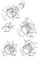
- FIG. 1is a perspective view of the novel hose clamp with the clamp in unstressed position, with the hose shown in phantom.
- FIG. 2is a view similar to FIG. 1 with the clamp in stressed position.
- FIG. 3is a view similar to FIG. 1 illustrating a modified form of the invention.
- FIG. 4is a section taken along lines 4 — 4 of FIG. 3 .
- FIG. 5is a view similar to FIG. 2, showing the modified clamp.
- FIGS. 1 and 2illustrate a preferred form of the novel spring band clamp 11 mounted on a typical hose 12 (shown in phantom).
- the clamphas a principal clamping portion 13 and first and second ends 14 and 15 which overlap each other in the same plane. This is accomplished by providing a slot or opening 16 in the portion 13 which is adjacent the first end 14 into which second end 15 extends.
- the clampis formed of a spring steel material of the type referred to in the prior art devices referred to above, and will exert radial pressure upon the hose being clamped when the clamp is in radially stressed position.
- the term “radially stressed”refers to the condition of the clamp when no effort is made to force the ends toward each other by any external forces other than external radial pressure of the hose upon the clamp. This condition is illustrated in FIG. 2 .
- the opposite position of the clampis “radially unstressed”, which refers to the condition wherein the ends are forced together under external forces so that the clamp has a larger diameter than in the radially stressed condition and will fit loosely around the outer surface of the hose. This position is shown in FIG. 1 .
- the first end 14has a radially outwardly extending tab 17 at approximately right angles to the end.
- the tab 17has an integral stop member 18 extending inwardly therefrom at an angle of approximately 135 degrees, having a function described below.
- the second end 15has a similar tab 19 also extending at about right angles to the end.
- the stop member 18engages the surface of tab 19 when the tabs are squeezed toward each other, and held in place by use of fingers or by use of an external tool 20 , which is shown in exploded position.
- the tabs 17 and 19are squeezed together using a hand tool or other special equipment. At this position the tabs are spaced about 30 degrees apart. In this position the clamp is placed loosely around the hose by slipping it over the end thereof, but may be glued or taped in place, if desired.
- a plurality of parallel slots 21are formed transversely through the clamping portion 13 adjacent the end 15 , and serve as locking members. These are used in conjunction with stop member 18 to achieve the radially stressed position of FIG. 2, in the following manner.
- the retaining force shown in FIG. 1is released after the clamp is positioned around the hose such as by removing the tool 20 .
- Thisallows the clamp to be forced radially inward due to the inherent forces of the spring band, the end 15 moving into slot 16 , and the clamp then reaches the smallest possible closed diameter which the hose diameter will allow.
- the stop member 18engages the locking member 21 which is thus automatically selected. At this position the tabs are spaced approximately 90 degrees apart. The inter-engagement of the member 18 and 21 will maintain constant optimum clamping action regardless of increased internal forces in the hose.
- FIG. 3illustrates a modified form of the invention comprising a clamp 22 which is similar to clamp 11 except for the formation of the locking arrangement.
- the clamp 22also shown in radially unstressed position, comprises a principal clamping portion 23 and ends 24 and 25 , having outwardly extending tabs 26 and 27 similar to tabs 17 and 19 .
- the stop member 28which is an integral part of tab 26 , has a curved end configuration.
- the locking members 30are not formed of a series of slots such as slots 21 of clamp 11 , but instead are formed of a series of transversely extending shoulders 31 , into which curved end of the stop member 28 is engaged as best shown in FIG. 4 .
Landscapes
- Engineering & Computer Science (AREA)
- General Engineering & Computer Science (AREA)
- Mechanical Engineering (AREA)
- Joints That Cut Off Fluids, And Hose Joints (AREA)
Abstract
Description
Claims (20)
Priority Applications (1)
| Application Number | Priority Date | Filing Date | Title |
|---|---|---|---|
| US09/652,631US6473943B1 (en) | 2000-08-31 | 2000-08-31 | Hose clamp |
Applications Claiming Priority (1)
| Application Number | Priority Date | Filing Date | Title |
|---|---|---|---|
| US09/652,631US6473943B1 (en) | 2000-08-31 | 2000-08-31 | Hose clamp |
Publications (1)
| Publication Number | Publication Date |
|---|---|
| US6473943B1true US6473943B1 (en) | 2002-11-05 |
Family
ID=24617542
Family Applications (1)
| Application Number | Title | Priority Date | Filing Date |
|---|---|---|---|
| US09/652,631Expired - Fee RelatedUS6473943B1 (en) | 2000-08-31 | 2000-08-31 | Hose clamp |
Country Status (1)
| Country | Link |
|---|---|
| US (1) | US6473943B1 (en) |
Cited By (24)
| Publication number | Priority date | Publication date | Assignee | Title |
|---|---|---|---|---|
| US6773036B1 (en)* | 2002-05-03 | 2004-08-10 | Tom King Harmony Products, Inc. | Saddle tee, saddle tee and tap, and fluid connection for irrigation lines |
| US20050038374A1 (en)* | 2001-11-21 | 2005-02-17 | E-Z-Em, Inc. | Device, system, kit or method for collecting effluent from an individual |
| US6898825B1 (en) | 2003-08-18 | 2005-05-31 | Scott R. Charest | Hose clamp |
| US20060100500A1 (en)* | 2004-06-03 | 2006-05-11 | E-Z-Em, Inc. | System, imaging suite, and method for using an electro-pneumatic insufflator for magnetic resonance imaging |
| DE102006027071A1 (en)* | 2006-06-13 | 2007-12-20 | Volkswagen Ag | Hose clamp for fastening a hose assembly on a pipe connection piece has a curved flexible band shaped like a ring with middle and end sections |
| US20090083950A1 (en)* | 2007-10-01 | 2009-04-02 | Thomas Corogin | Clamp |
| US20090171268A1 (en)* | 2004-04-23 | 2009-07-02 | Williams Jr Robert C | Manually Operated Insufflator |
| WO2010013563A1 (en) | 2008-07-28 | 2010-02-04 | Yazaki Corporation | Electrical wire fixing member |
| US20110074116A1 (en)* | 2009-09-29 | 2011-03-31 | Press-Seal Gasket Corporation | Collapsible expansion mechanism for effecting a seal |
| US8172276B1 (en) | 2006-10-06 | 2012-05-08 | Blazing Products, Inc. | Fittings connectable to end portions of pipes and related methods |
| US8662541B2 (en) | 2009-04-01 | 2014-03-04 | Blazing Products, Inc. | Fittings for sealed retention to end portions of pipes and related methods |
| US8720907B2 (en) | 2010-03-23 | 2014-05-13 | Press-Seal Gasket Corporation | Expansion ring assembly |
| US9297486B2 (en) | 2006-10-06 | 2016-03-29 | Blazing Products, Inc. | Pipe fittings with insert retaining seals and related methods |
| US9561335B2 (en) | 2010-11-24 | 2017-02-07 | Bracco Diagnostics Inc. | System, device, and method for providing and controlling the supply of a distending media for CT colonography |
| US9593789B2 (en) | 2006-10-06 | 2017-03-14 | Blazing Products, Inc. | Pipe-fitting with adaptor assembly and related methods |
| US9987439B2 (en) | 2005-10-24 | 2018-06-05 | United States Endoscopy Group, Inc. | Insufflating system, method, and computer program product for controlling the supply of a distending media to an endoscopic device |
| US10005600B2 (en)* | 2013-07-02 | 2018-06-26 | Togo Seisakusyo Corporation | Hose clamp |
| US10036500B2 (en)* | 2014-02-04 | 2018-07-31 | Piolax, Inc. | Hose clamp |
| US10092234B2 (en) | 2007-10-15 | 2018-10-09 | University Of Maryland, Baltimore | Apparatus and method for use in analyzing a patient'S bowel |
| US10550979B2 (en) | 2017-02-02 | 2020-02-04 | North American Pipe Corporation | System for conduit squeeze retainer |
| US10610054B2 (en)* | 2016-08-29 | 2020-04-07 | Weber-Stephen Products Llc | Ash catcher and support clip for grills |
| US10801654B2 (en) | 2006-10-06 | 2020-10-13 | King Technology Of Missouri, Llc | Tubular pipe fitting insert with interior reinforcement ribs |
| US11098834B2 (en) | 2017-09-18 | 2021-08-24 | North American Pipe Corporation | System, method and apparatus for debris shield for squeeze-activated retainer for a conduit |
| US20220396387A1 (en)* | 2019-11-12 | 2022-12-15 | Genbe Co., Ltd. | Collecting tool |
Citations (10)
| Publication number | Priority date | Publication date | Assignee | Title |
|---|---|---|---|---|
| GB977757A (en)* | 1961-11-18 | 1964-12-16 | Jurid Werke Gmbh | Improvements in or relating to hose clamping straps |
| US4483556A (en)* | 1982-09-22 | 1984-11-20 | Dayco Corporation | Hose clamp for a wire reinforced hose |
| US4882814A (en) | 1988-05-20 | 1989-11-28 | Kato Hatsujo Kaisha, Ltd. | Hose clamp furnished with tacking function |
| US5115541A (en)* | 1990-02-22 | 1992-05-26 | Rasmussen Gmbh | Hose clip |
| US5414905A (en)* | 1992-04-13 | 1995-05-16 | Togo Seisakusho Corporation | Hose clip |
| US5620209A (en) | 1995-02-22 | 1997-04-15 | Rasmussen Gmbh | Device for clamping a hose end section fitted onto a pipe end section |
| US5675871A (en) | 1996-10-10 | 1997-10-14 | Acd Tridon Inc. | Hose clamp location device |
| US5706557A (en) | 1995-10-24 | 1998-01-13 | Rasmussen Gmbh | Spring band hose clamp |
| US5864926A (en)* | 1996-09-09 | 1999-02-02 | Rasmussen Gmbh | Spring band clamp |
| US5996186A (en) | 1997-10-17 | 1999-12-07 | Piolax, Inc. | Hose clamp |
- 2000
- 2000-08-31USUS09/652,631patent/US6473943B1/ennot_activeExpired - Fee Related
Patent Citations (10)
| Publication number | Priority date | Publication date | Assignee | Title |
|---|---|---|---|---|
| GB977757A (en)* | 1961-11-18 | 1964-12-16 | Jurid Werke Gmbh | Improvements in or relating to hose clamping straps |
| US4483556A (en)* | 1982-09-22 | 1984-11-20 | Dayco Corporation | Hose clamp for a wire reinforced hose |
| US4882814A (en) | 1988-05-20 | 1989-11-28 | Kato Hatsujo Kaisha, Ltd. | Hose clamp furnished with tacking function |
| US5115541A (en)* | 1990-02-22 | 1992-05-26 | Rasmussen Gmbh | Hose clip |
| US5414905A (en)* | 1992-04-13 | 1995-05-16 | Togo Seisakusho Corporation | Hose clip |
| US5620209A (en) | 1995-02-22 | 1997-04-15 | Rasmussen Gmbh | Device for clamping a hose end section fitted onto a pipe end section |
| US5706557A (en) | 1995-10-24 | 1998-01-13 | Rasmussen Gmbh | Spring band hose clamp |
| US5864926A (en)* | 1996-09-09 | 1999-02-02 | Rasmussen Gmbh | Spring band clamp |
| US5675871A (en) | 1996-10-10 | 1997-10-14 | Acd Tridon Inc. | Hose clamp location device |
| US5996186A (en) | 1997-10-17 | 1999-12-07 | Piolax, Inc. | Hose clamp |
Cited By (37)
| Publication number | Priority date | Publication date | Assignee | Title |
|---|---|---|---|---|
| US10758399B2 (en) | 2001-11-21 | 2020-09-01 | Bracco Diagnostics Inc. | Device, system, kit or method for collecting effluent from an individual |
| US20050038374A1 (en)* | 2001-11-21 | 2005-02-17 | E-Z-Em, Inc. | Device, system, kit or method for collecting effluent from an individual |
| US8771245B2 (en) | 2001-11-21 | 2014-07-08 | Bracco Diagnostics Inc. | Device, system, kit or method for collecting effluent from an individual |
| US8057448B2 (en) | 2001-11-21 | 2011-11-15 | Bracco Diagnostics Inc. | Device, system, kit or method for collecting effluent from an individual |
| US7361170B2 (en) | 2001-11-21 | 2008-04-22 | E-Z-Em, Inc. | Device, system, kit or method for collecting effluent from an individual |
| US20080228154A1 (en)* | 2001-11-21 | 2008-09-18 | E-Z-Em, Inc. | Device, system, kit or method for collecting effluent from an individual |
| US6773036B1 (en)* | 2002-05-03 | 2004-08-10 | Tom King Harmony Products, Inc. | Saddle tee, saddle tee and tap, and fluid connection for irrigation lines |
| US6898825B1 (en) | 2003-08-18 | 2005-05-31 | Scott R. Charest | Hose clamp |
| US20090171268A1 (en)* | 2004-04-23 | 2009-07-02 | Williams Jr Robert C | Manually Operated Insufflator |
| US20060100500A1 (en)* | 2004-06-03 | 2006-05-11 | E-Z-Em, Inc. | System, imaging suite, and method for using an electro-pneumatic insufflator for magnetic resonance imaging |
| US9987439B2 (en) | 2005-10-24 | 2018-06-05 | United States Endoscopy Group, Inc. | Insufflating system, method, and computer program product for controlling the supply of a distending media to an endoscopic device |
| DE102006027071A1 (en)* | 2006-06-13 | 2007-12-20 | Volkswagen Ag | Hose clamp for fastening a hose assembly on a pipe connection piece has a curved flexible band shaped like a ring with middle and end sections |
| US10801654B2 (en) | 2006-10-06 | 2020-10-13 | King Technology Of Missouri, Llc | Tubular pipe fitting insert with interior reinforcement ribs |
| US8172276B1 (en) | 2006-10-06 | 2012-05-08 | Blazing Products, Inc. | Fittings connectable to end portions of pipes and related methods |
| US8596691B2 (en) | 2006-10-06 | 2013-12-03 | Blazing Products, Inc. | Fittings connectable to end portions of pipes and related methods |
| US9593789B2 (en) | 2006-10-06 | 2017-03-14 | Blazing Products, Inc. | Pipe-fitting with adaptor assembly and related methods |
| US9297486B2 (en) | 2006-10-06 | 2016-03-29 | Blazing Products, Inc. | Pipe fittings with insert retaining seals and related methods |
| US20090083950A1 (en)* | 2007-10-01 | 2009-04-02 | Thomas Corogin | Clamp |
| USD709994S1 (en) | 2007-10-05 | 2014-07-29 | Blazing Products, Inc. | Insert portion of a pipe fitting |
| US10092234B2 (en) | 2007-10-15 | 2018-10-09 | University Of Maryland, Baltimore | Apparatus and method for use in analyzing a patient'S bowel |
| US10702204B2 (en) | 2007-10-15 | 2020-07-07 | University Of Maryland, Baltimore | Apparatus and method for use in analyzing a patient's bowel |
| WO2010013563A1 (en) | 2008-07-28 | 2010-02-04 | Yazaki Corporation | Electrical wire fixing member |
| US20110108680A1 (en)* | 2008-07-28 | 2011-05-12 | Yazaki Corporation | Electrical wire fixing member |
| EP2318721A4 (en)* | 2008-07-28 | 2017-05-17 | Yazaki Corporation | Electrical wire fixing member |
| US8336834B2 (en)* | 2008-07-28 | 2012-12-25 | Yazaki Corporation | Electrical wire fixing member |
| US8662541B2 (en) | 2009-04-01 | 2014-03-04 | Blazing Products, Inc. | Fittings for sealed retention to end portions of pipes and related methods |
| US20110074116A1 (en)* | 2009-09-29 | 2011-03-31 | Press-Seal Gasket Corporation | Collapsible expansion mechanism for effecting a seal |
| US8720907B2 (en) | 2010-03-23 | 2014-05-13 | Press-Seal Gasket Corporation | Expansion ring assembly |
| US9561335B2 (en) | 2010-11-24 | 2017-02-07 | Bracco Diagnostics Inc. | System, device, and method for providing and controlling the supply of a distending media for CT colonography |
| US10005600B2 (en)* | 2013-07-02 | 2018-06-26 | Togo Seisakusyo Corporation | Hose clamp |
| US10036500B2 (en)* | 2014-02-04 | 2018-07-31 | Piolax, Inc. | Hose clamp |
| US10610054B2 (en)* | 2016-08-29 | 2020-04-07 | Weber-Stephen Products Llc | Ash catcher and support clip for grills |
| US10550979B2 (en) | 2017-02-02 | 2020-02-04 | North American Pipe Corporation | System for conduit squeeze retainer |
| US12264763B2 (en) | 2017-02-02 | 2025-04-01 | Westlake Pipe &Fittings Corporation | System for conduit squeeze retainer |
| US11098834B2 (en) | 2017-09-18 | 2021-08-24 | North American Pipe Corporation | System, method and apparatus for debris shield for squeeze-activated retainer for a conduit |
| US20220396387A1 (en)* | 2019-11-12 | 2022-12-15 | Genbe Co., Ltd. | Collecting tool |
| US12252290B2 (en)* | 2019-11-12 | 2025-03-18 | Genbe Co., Ltd | Collecting tool |
Similar Documents
| Publication | Publication Date | Title |
|---|---|---|
| US6473943B1 (en) | Hose clamp | |
| US5669590A (en) | Retaining clip with multiple clamps | |
| US3995897A (en) | Coupling | |
| EP0928389B1 (en) | Hose clamp location device | |
| US5855044A (en) | Hose clamp with claw | |
| EP3833896B1 (en) | Clamp assembly with retainer | |
| US20100058563A1 (en) | Clamp Securement | |
| US2472172A (en) | Hose clamp | |
| KR102237354B1 (en) | Antirotation band for hydraulic connector | |
| US20140090875A1 (en) | Cold shrink assembly | |
| JPS5980514A (en) | Sash clip with no screw | |
| KR100391196B1 (en) | Holderless hose clamp | |
| JP3513237B2 (en) | Automatic tightening clamp structure | |
| KR101785632B1 (en) | water and sewage pipe set integrated with protective socket for improved water tightness by prevent breakage of connection end and prevent separation of the pipes | |
| WO2010092702A1 (en) | Hose clamp | |
| US4754531A (en) | Elastic tie down | |
| JP2001280566A (en) | Hose clamp | |
| US9739401B1 (en) | Pipe gripping elements and pipe joint restraints incorporating same | |
| US10036500B2 (en) | Hose clamp | |
| US7228609B2 (en) | Extractor | |
| US3836184A (en) | Pipe coupling | |
| JP2010019311A (en) | Connection structure and connection method of pipe to joint | |
| US6481062B1 (en) | Fastening belt | |
| JP3543215B2 (en) | Pipe fittings | |
| KR200362507Y1 (en) | Clamp for hose |
Legal Events
| Date | Code | Title | Description |
|---|---|---|---|
| AS | Assignment | Owner name:DAYCO PRODUCTS, INC., OHIO Free format text:ASSIGNMENT OF ASSIGNORS INTEREST;ASSIGNOR:THACKER, JAMES C.;REEL/FRAME:011226/0636 Effective date:20000828 | |
| AS | Assignment | Owner name:DAYCO PRODUCTS, LLC, OHIO Free format text:CHANGE OF NAME;ASSIGNOR:DAYCO PRODUCTS, INC.;REEL/FRAME:014863/0103 Effective date:20000912 | |
| REMI | Maintenance fee reminder mailed | ||
| FPAY | Fee payment | Year of fee payment:4 | |
| SULP | Surcharge for late payment | ||
| AS | Assignment | Owner name:FLUID ROUTING SOLUTIONS, INC., MICHIGAN Free format text:ASSIGNMENT OF ASSIGNORS INTEREST;ASSIGNOR:DAYCO PRODUCTS, LLC;REEL/FRAME:019562/0478 Effective date:20070524 | |
| AS | Assignment | Owner name:WELLS FARGO FOOTHILL, INC., AS ADMINISTRATIVE AGEN Free format text:SECURITY AGREEMENT;ASSIGNORS:FLUID ROUTING SOLUTIONS, INC.;FLUID ROUTING SOLUTIONS AUTOMOTIVE, LLC;DETROIT FUEL, INC.;AND OTHERS;REEL/FRAME:019668/0301 Effective date:20070730 | |
| AS | Assignment | Owner name:SUN FLUID ROUTING FINANCE, LLC, FLORIDA Free format text:PATENT SECURITY AGREEMENT;ASSIGNORS:FLUID ROUTING SOLUTIONS, INC.;FLUID ROUTING SOLUTIONS AUTOMOTIVE, LLC;DETROIT FUEL, INC.;REEL/FRAME:021096/0865 Effective date:20080616 | |
| AS | Assignment | Owner name:FLUID ROUTING SOLUTIONS, INC., MICHIGAN Free format text:RELEASE OF SECURITY INTEREST RECORDED AT REEL/FRAME 019668/0301;ASSIGNOR:WELLS FARGO FOOTHILL, INC.;REEL/FRAME:022460/0171 Effective date:20090327 Owner name:FLUID ROUTING SOLUTIONS AUTOMOTIVE, LLC, MICHIGAN Free format text:RELEASE OF SECURITY INTEREST RECORDED AT REEL/FRAME 019668/0301;ASSIGNOR:WELLS FARGO FOOTHILL, INC.;REEL/FRAME:022460/0171 Effective date:20090327 Owner name:DETROIT FUEL, INC., MICHIGAN Free format text:RELEASE OF SECURITY INTEREST RECORDED AT REEL/FRAME 019668/0301;ASSIGNOR:WELLS FARGO FOOTHILL, INC.;REEL/FRAME:022460/0171 Effective date:20090327 Owner name:FLUID ROUTING SOLUTIONS INTERMEDIATE HOLDINGS CORP Free format text:RELEASE OF SECURITY INTEREST RECORDED AT REEL/FRAME 019668/0301;ASSIGNOR:WELLS FARGO FOOTHILL, INC.;REEL/FRAME:022460/0171 Effective date:20090327 Owner name:FRS GROUP, LP, FLORIDA Free format text:SECURITY AGREEMENT;ASSIGNOR:FRS HOLDING CORP.;REEL/FRAME:022460/0214 Effective date:20090327 Owner name:FRS GROUP, LP,FLORIDA Free format text:SECURITY AGREEMENT;ASSIGNOR:FRS HOLDING CORP.;REEL/FRAME:022460/0214 Effective date:20090327 | |
| AS | Assignment | Owner name:FRS HOLDING CORP., MICHIGAN Free format text:ASSIGNMENT OF ASSIGNORS INTEREST;ASSIGNOR:FLUID ROUTING SOLUTIONS, INC.;REEL/FRAME:023379/0627 Effective date:20090327 Owner name:FRS HOLDING CORP.,MICHIGAN Free format text:ASSIGNMENT OF ASSIGNORS INTEREST;ASSIGNOR:FLUID ROUTING SOLUTIONS, INC.;REEL/FRAME:023379/0627 Effective date:20090327 | |
| AS | Assignment | Owner name:FLUID ROUTING SOLUTIONS, INC., MICHIGAN Free format text:CHANGE OF NAME;ASSIGNOR:FRS HOLDING CORP.;REEL/FRAME:023390/0031 Effective date:20090330 Owner name:FLUID ROUTING SOLUTIONS, INC.,MICHIGAN Free format text:CHANGE OF NAME;ASSIGNOR:FRS HOLDING CORP.;REEL/FRAME:023390/0031 Effective date:20090330 | |
| AS | Assignment | Owner name:FLUID ROUTING SOLUTIONS, INC.,MICHIGAN Free format text:PARTIAL RELEASE OF SECURITY INTEREST RECORDED AT REEL/FRAME 021096/0865;ASSIGNOR:FRS GROUP, LP, AS SUCCESSOR BY CONVERSION OF SUN FLUID ROUTING FINANCE, LLC;REEL/FRAME:024515/0079 Effective date:20100607 | |
| AS | Assignment | Owner name:BMO CAPITAL MARKETS FINANCING, INC.,ILLINOIS Free format text:ASSIGNMENT OF SECURITY INTEREST RECORDED AT REEL/FRAME 022460/0214;ASSIGNOR:FRS GROUP, LP;REEL/FRAME:024515/0708 Effective date:20100607 Owner name:BANK OF MONTREAL,ILLINOIS Free format text:ASSIGNMENT OF SECURITY INTEREST RECORDED AT REEL/FRAME 022460/0214;ASSIGNOR:FRS GROUP, LP;REEL/FRAME:024515/0708 Effective date:20100607 Owner name:BANK OF MONTREAL, ILLINOIS Free format text:ASSIGNMENT OF SECURITY INTEREST RECORDED AT REEL/FRAME 022460/0214;ASSIGNOR:FRS GROUP, LP;REEL/FRAME:024515/0708 Effective date:20100607 Owner name:BMO CAPITAL MARKETS FINANCING, INC., ILLINOIS Free format text:ASSIGNMENT OF SECURITY INTEREST RECORDED AT REEL/FRAME 022460/0214;ASSIGNOR:FRS GROUP, LP;REEL/FRAME:024515/0708 Effective date:20100607 | |
| REMI | Maintenance fee reminder mailed | ||
| AS | Assignment | Owner name:FRS GROUP, LP, MICHIGAN Free format text:RELEASE BY SECURED PARTY;ASSIGNORS:BMO CAPITAL MARKETS FINANCING, INC.;BANK OF MONTREAL;REEL/FRAME:025114/0285 Effective date:20101007 | |
| LAPS | Lapse for failure to pay maintenance fees | ||
| STCH | Information on status: patent discontinuation | Free format text:PATENT EXPIRED DUE TO NONPAYMENT OF MAINTENANCE FEES UNDER 37 CFR 1.362 | |
| FP | Lapsed due to failure to pay maintenance fee | Effective date:20101105 |