US6473631B1 - Video swivel phone - Google Patents
Video swivel phoneDownload PDFInfo
- Publication number
- US6473631B1 US6473631B1US09/466,645US46664599AUS6473631B1US 6473631 B1US6473631 B1US 6473631B1US 46664599 AUS46664599 AUS 46664599AUS 6473631 B1US6473631 B1US 6473631B1
- Authority
- US
- United States
- Prior art keywords
- video
- phone
- user
- module
- ear
- Prior art date
- Legal status (The legal status is an assumption and is not a legal conclusion. Google has not performed a legal analysis and makes no representation as to the accuracy of the status listed.)
- Expired - Lifetime
Links
- 238000004891communicationMethods0.000abstractdescription16
- 230000003750conditioning effectEffects0.000description6
- 238000005516engineering processMethods0.000description6
- 230000001413cellular effectEffects0.000description5
- 230000006835compressionEffects0.000description4
- 238000007906compressionMethods0.000description4
- 230000003466anti-cipated effectEffects0.000description3
- 238000007667floatingMethods0.000description3
- 230000006870functionEffects0.000description3
- 238000004091panningMethods0.000description3
- 230000000694effectsEffects0.000description2
- 230000004044responseEffects0.000description2
- 230000005236sound signalEffects0.000description2
- HBBGRARXTFLTSG-UHFFFAOYSA-NLithium ionChemical compound[Li+]HBBGRARXTFLTSG-UHFFFAOYSA-N0.000description1
- 230000009471actionEffects0.000description1
- 230000005540biological transmissionEffects0.000description1
- 238000010276constructionMethods0.000description1
- 230000007812deficiencyEffects0.000description1
- 238000010586diagramMethods0.000description1
- 230000006872improvementEffects0.000description1
- 229910001416lithium ionInorganic materials0.000description1
- 230000007246mechanismEffects0.000description1
- 230000004048modificationEffects0.000description1
- 238000012986modificationMethods0.000description1
- 230000000284resting effectEffects0.000description1
Images

Classifications
- H—ELECTRICITY
- H04—ELECTRIC COMMUNICATION TECHNIQUE
- H04M—TELEPHONIC COMMUNICATION
- H04M1/00—Substation equipment, e.g. for use by subscribers
- H04M1/02—Constructional features of telephone sets
- H04M1/03—Constructional features of telephone transmitters or receivers, e.g. telephone hand-sets
- H04M1/035—Improving the acoustic characteristics by means of constructional features of the housing, e.g. ribs, walls, resonating chambers or cavities
- H—ELECTRICITY
- H04—ELECTRIC COMMUNICATION TECHNIQUE
- H04M—TELEPHONIC COMMUNICATION
- H04M1/00—Substation equipment, e.g. for use by subscribers
- H04M1/02—Constructional features of telephone sets
- H04M1/0202—Portable telephone sets, e.g. cordless phones, mobile phones or bar type handsets
- H04M1/026—Details of the structure or mounting of specific components
- H04M1/0264—Details of the structure or mounting of specific components for a camera module assembly
- H—ELECTRICITY
- H04—ELECTRIC COMMUNICATION TECHNIQUE
- H04M—TELEPHONIC COMMUNICATION
- H04M2250/00—Details of telephonic subscriber devices
- H04M2250/20—Details of telephonic subscriber devices including a rotatable camera
- H—ELECTRICITY
- H04—ELECTRIC COMMUNICATION TECHNIQUE
- H04N—PICTORIAL COMMUNICATION, e.g. TELEVISION
- H04N7/00—Television systems
- H04N7/14—Systems for two-way working
- H04N7/141—Systems for two-way working between two video terminals, e.g. videophone
- H04N7/142—Constructional details of the terminal equipment, e.g. arrangements of the camera and the display
- H04N2007/145—Handheld terminals
Definitions
- This inventionrelates in general to wireless communication devices that can capture and transmit video images and that can receive and display video images, and more particularly to a portable videophone.
- wireless communication devicessuch as cellular telephones, cordless telephones, two-way wireless communicators, and other such two-way portable wireless communication devices, are including powerful and fast processors capable of managing video signals and compression for communication over a wireless communication channel. Therefore, with the combination of the aforementioned technologies it is becoming commercially practicable to offer wireless communication devices capable of capturing and transmitting video images and receiving and displaying video images to provide a wireless video phone consumer product.
- a telephone unitcomprises a handset that includes an ear portion and a mouth portion for a user to listen and to speak over the telephone.
- a wireless communication devicesuch as a cellular telephone or cordless telephone includes an ear portion and a mouth portion for listening and for speaking.
- the ear portion in these devicesis normally constructed suitable for resting in close proximity to a users ear.
- the mouth portionnormally includes a microphone transducer with an audio response profile directed generally in the vicinity of the user's mouth.
- a video camera lensis typically located in a fixed location allowing the user to move into or out of a fixed video scene.
- the captured video image of the video sceneis delivered from the video camera device in the telephone unit across a wired network, such as the public switched telephone network (PSTN) to another receiving device that can display the image on a screen of a video display.
- PSTNpublic switched telephone network
- capturing a fixed video scenehas its merits, such as allowing the user to move into and out of the fixed scene, this arrangement lacks flexibility for the user in certain applications. For example, the user may wish to capture a moving scene rather than a fixed scene. In such a case, the user would typically have to pan the entire telephone communication device across a field of view to create a moving scene.
- This panning activitywill typically also move the audio input and output portions of the unit.
- the usermay be precluded from speaking and/or listening via the telephone unit due to the panning activity.
- the telephone unitincludes a video display screen then the user may also be precluded from viewing the video display screen during the panning action.
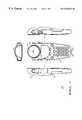
- FIG. 1comprises front, right, left, and top, planar views of an exemplary video swivel phone according to a preferred embodiment of the present invention.
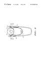
- FIG. 2is a rear planar view of the video swivel phone of FIG. 1 in accordance with a preferred embodiment of the present invention.
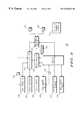
- FIG. 3is an electrical block diagram illustrating an exemplary electrical circuit model for the video swivel phone of FIG. 1 according to a preferred embodiment of the present invention.
- FIG. 4is a front perspective view of an exemplary video swivel phone according to an alternative preferred embodiment of the present invention.
- an exemplary video swivel phone 100includes an ear portion, or ear cup 102 , and provides an ear audio output transducer 104 located in the ear portion to deliver an audio signal to a user's ear during communication.
- the phone 100also includes a mouth portion, or microphone audio input 106 , that receives audio input generally directed from the user's mouth.
- the ear audio output transducer 104 and the microphone audio input 106are arranged on the video swivel phone 100 for using the video swivel phone as an ear-to-mouth audio phone communication device.
- a speakerphone audio output 108provides the user with an alternative means of audio communication via the phone 100 .
- the speaker phone audio output 108in combination with the microphone audio input 106 allows the user to use the phone 100 similar to a speaker phone. The user can speak into the microphone audio input 106 and can listen via the speakerphone audio output 108 .
- a set of keys, or keypad 110provide a means for user input into the phone 100 . These keys 110 can be used to enter control and/or data user input into the phone 100 . Other forms of user input means are also anticipated as would be obvious to those of ordinary skill in the art.
- a push-to-talk switch 112is included in the exemplary phone 100 to allow the user control over when to activate the microphone audio input 106 to capture audio input into the phone 100 . When the push-to-talk switch 112 is released normally the phone 100 is in an audio output mode delivering audio output to the ear audio output transducer 104 and/or the speaker phone audio output 108 as may be required by a mode of communication with the user.
- buttons 114may be used to control certain functions of the phone 100 .
- the buttons 114can control the level of audio a output.
- One buttoncan be pushed by the user to raise the level of audio output and the other button can be pushed by the user to lower the level of audio output, such as to adjust the level of audio output in response to varying ambient noise audio conditions.
- a video display screen 116is included in the phone 100 to provide the user with moving video images that are received from a remote video capturing device such as another video phone being used by another person to communicate with the user of the video phone 100 .
- the video display screen 116can be constructed for monochrome video image display and alternatively for color video image display as may be desired by particular applications. With the advent of powerful compression algorithms and embedded microprocessors in portable devices such as the videophone 100 it is commercially feasible to wirelessly communicate the larger amount of information utilized in delivering color video images to the user.
- a miniaturized charge couple device (CCD) based video camera 118in the preferred embodiment, is located in a substantially opposing arrangement to the ear cup 102 .
- the video camera 118includes a lens 119 that is aiming generally in an opposing direction to the ear cup 102 .
- the lens 119is recessed into the housing for the ear portion of the phone 100 to protect the lens from direct contact with external surfaces when the phone 100 is, for example, located on top of another object such as a table top.
- the userBy locating the video camera 118 in a substantially opposing arrangement to the ear cup 102 the user is able to view the video display screen 116 , for example, while the video camera is aimed outwardly toward a subject who's moving image is being captured by the video camera. Further, the user can view on the video display screen 116 the moving image being captured by the video camera 118 .
- the ear portion of the phone 100comprises a floating module arrangement as will be discussed below.
- the ear cup 102 and the video camera 118are contained in a housing module that is cradled between, in this example, support bearings 204 , 206 , which extend from the main housing of the phone 100 .
- These bearings 204 , 206are formed as the front and rear halves of a main phone housing are attached to each other.
- the main housingcomprises a handheld portion of the phone 100 .
- the usercan manually hold the phone 100 while orienting the ear cup 102 and the video camera 118 as discussed below.
- the pivoting or floating module 202is suspended between the bearings 204 , 206 , by an integrated perpendicular shaft extending through a centerline of the pivoting module 202 .
- the pivoting module 202can rotate 208 about an axis generally formed by these bearings 204 , 206 .
- rotation about another axisis anticipated by the present invention as may be obvious to one of ordinary skill in the art.
- electrical connection from the main phone housing to the pivoting module 202is routed via the bearings 204 , 206 .
- a shaf-mounted pair of stopspermit rotation or pivoting about a limited angular distance, such as 180 degrees. In this way, the video camera 118 can be aimed outwardly toward a subject or a scene for capturing video images while viewing the images on the video display screen 116 .
- the floating module 202can also be pivoted to aim the video camera 118 directly at the user of the phone 100 to utilize the phone 100 in a video conferencing application.
- the image of the useris captured by the video camera 118 and transmitted to the phone unit of another user while the video image of the other user is transmitted from the other unit and received and displayed on the video display screen 116 during the video conference application.
- the speaker phone audio output 108 and the microphone audio input 106provide audio I/O for the video conferencing application.
- the pivoting modulecan be arranged to continuously rotate about the axis of the bearings 204 , 206 , as discussed below.
- the continuously rotatable module configurationdoes not include the stops.
- the electrical interconnection between the continuously rotatable module 202 and the main housing of the phone 100utilizes electrical contacts that maintain electrical connection while the pivoting module 202 continuously rotates about the axis of the bearings 204 , 206 .
- Thisis accomplished, for example, by utilizing spring loaded contacts which rest against a rotary contact shaft parallel to the axis of rotation.
- Thisis similar to commonly available “tangle eliminators” used for corded telephone handsets and similar devices. It allows unlimited rotation with continuous electrical contact.
- a latched door 120can be removed to expose a battery compartment.
- the battery for the phone 100is preferably rechargeable and replaceable. As illustrated in FIG. 3, the a battery power source 312 supplies power to all the electrical circuits in the video swivel phone 100 .
- the battery 312preferably comprises lithium ion technology. However, other suitable rechargeable battery technology may be substituted to supply the necessary power for the electrical circuits.
- the controller 302operates with the memory 304 to provide functions and features of the phone 100 as will be discussed below.
- the phone 100comprises a wireless cellular phone technology.
- Such wireless cellular phone technologyis commercially available in the iDEN 1000 cellular phone product manufactured by Motorola Inc. of Schaumburg Illinois, U.S.A.
- the controller 302is powerful enough to handle video compression algorithms that are commercially available today.
- the user input 305is electrically coupled to the controller 302 to monitor and receive input from the user of the videophone 100 .
- the user input 305for example, comprises the keypad 110 , and the push-to-talk button 112 and the audio level control buttons 114 . See FIG. 1 .
- other suitable user input meansare anticipated by the present invention as are well known to those of ordinary skill in the art.
- An encoder/decoder module 306is electrically coupled to the controller 302 and to a receiver module 308 and to a transmitter module 310 .
- a transmitted messageis received by the receiver module 308 and then decoded by the decoder module 306 .
- Video image information contained in the received messagescan be displayed on the video display screen.
- messagescan be encoded by the encoder 306 and then transmitted by the transmitter module 310 .
- the transmitted messagescontain image information corresponding to captured images such as captured by the video camera 118 . In this way, messages, typically transmitted in packets of information, are wirelessly received and/or transmitted by the videophone 100 . This wireless message communication mechanism is well known to those of ordinary skill in the art.
- the controller 302 and the encoder/decoder module 306are electrically coupled to an audio control and conditioning module 314 .
- the audio control and conditioning module 314can be controlled by the controller 302 for multiplexing, amplifying, and conditioning audio signals between the audio I/O of the video phone 100 and the encoder/decoder module 306 .
- a microphone audio input transducer 316is electrically coupled to the audio control and conditioning module 314 .
- the microphone audio input module 316is shown as the microphone audio input 106 in FIG. 1 .
- An ear audio output transducer 318is electrically coupled to the audio control and conditioning module 314 .
- the ear audio output transducer 318generates audio output signals that can be provided to the user of the phone 100 such as via the ear audio output 104 in the ear cup 102 . See FIG. 1 .
- the speaker audio output transducer 320is also electrically coupled to the audio control and conditioning module 314 .
- the speaker audio output transducer 320is shown in FIG. 1 as part of the speakerphone audio output 108 .
- a video control module 322is electrically coupled to the controller 302 .
- the video control module 322is also electrically coupled to the encoder/decoder module 306 .
- Video signals that are part of messages being encoded/decoded by the encoder/decoder module 306are processed by the video control module 322 .
- Received and decoded video imagesare passed from the decoder 306 to the video control module 322 and then presented to the user via the video display module 324 .
- the usercan view the video images on the video display screen 116 .
- a charge coupled device based video camera input module 326is electrically coupled to the video control module 322 .
- the video camera input module 326captures video images such as via the video camera 118 as illustrated in FIG. 1 .
- the video control module 322can receive the video image information from the video camera input module 326 and route this information to the encoder 306 to create a message containing the video image information to be transmitted via the transmitter module 310 .
- the video camera input module 326provides the video input information to the video control module 322 which then forwards the video information to the video display module 324 to display the image on the video display screen 116 .
- the video camera input module 326 and the ear audio output module 318are located in the pivoting module 202 and are electrically coupled to the other electrical circuit elements of the video phone 100 through wire cabling that is routed via the bearings 204 , 206 , as discussed above.
- a set of continuously rotatable electrical contacts 330 , 340can be utilized to provide continuous electrical connection while the pivoting module 202 is continuously rotated about the axis of the bearings 204 , 206 .
- the construction use of such continuously rotatable electrical contacts 330 , 340has also been discussed above.
- the video swivel phone 100allows the user the flexibility to aim the lens 119 of the video camera module 118 in a number of directions while conveniently holding the phone 100 in the user's hand.
- the video camera 118can be aimed outwardly away from the user and capture video image of a subject while the user of the phone 100 can view the captured image on the video display screen 116 .
- the pivoting module 202can be rotated such that the lens 119 of the video camera 118 is aimed directly at the user while the user conducts a teleconference using the phone 100 .
- the phone 100operates like a speaker phone with audio input 106 and audio output 108 providing the speaker phone I/O functions.
- a video camera 402comprises a lens 404 located in a recess in the ear cup 406 .
- Ear audio output 408is also located in the ear cup 406 .
- the ear audio output 408is oriented about the rotatable portion 202 in substantially the same direction as the lens 404 .
- the ear cup 406conveniently allows the user's ear to listen to the audio output from the audio output module 408 and the microphone audio input 106 allows the user to speak into the phone 100 .
- the video camera 402is included in combination with the video camera 118 in one videophone unit 100 .
- Each video camera 404 , 118is electrically coupled to the video camera input module 326 and to the video control module 322 .
- This flexible arrangementallows the user to select, such as via the user input 110 , the source of the video input to the phone 100 . Either video camera 118 , 402 , or both can be selected as a source of video image input into the video phone 100 .
- the usercan engage in a video conference using the phone 100 while selectively capturing video input from the outwardly aiming video camera 118 to capture video images from a surrounding scene or a subject other than the user.
- Thisis an extremely flexible arrangement that is a significant improvement over any known video capture and transmission communication device.
Landscapes
- Engineering & Computer Science (AREA)
- Signal Processing (AREA)
- Physics & Mathematics (AREA)
- Acoustics & Sound (AREA)
- Two-Way Televisions, Distribution Of Moving Picture Or The Like (AREA)
- Telephone Set Structure (AREA)
Abstract
Description
Claims (5)
Priority Applications (1)
| Application Number | Priority Date | Filing Date | Title |
|---|---|---|---|
| US09/466,645US6473631B1 (en) | 1999-12-20 | 1999-12-20 | Video swivel phone |
Applications Claiming Priority (1)
| Application Number | Priority Date | Filing Date | Title |
|---|---|---|---|
| US09/466,645US6473631B1 (en) | 1999-12-20 | 1999-12-20 | Video swivel phone |
Publications (1)
| Publication Number | Publication Date |
|---|---|
| US6473631B1true US6473631B1 (en) | 2002-10-29 |
Family
ID=23852571
Family Applications (1)
| Application Number | Title | Priority Date | Filing Date |
|---|---|---|---|
| US09/466,645Expired - LifetimeUS6473631B1 (en) | 1999-12-20 | 1999-12-20 | Video swivel phone |
Country Status (1)
| Country | Link |
|---|---|
| US (1) | US6473631B1 (en) |
Cited By (63)
| Publication number | Priority date | Publication date | Assignee | Title |
|---|---|---|---|---|
| US20020015102A1 (en)* | 2000-03-27 | 2002-02-07 | Hisanori Itoh | Information communication apparatus |
| US20020021901A1 (en)* | 2000-06-28 | 2002-02-21 | Shuji Shimizu | Exposure control device for camera mounted on electronic apparatus |
| US20020058531A1 (en)* | 2000-11-10 | 2002-05-16 | Sanyo Electric Co., Ltd. | Mobile phone provided with video camera |
| US20020058536A1 (en)* | 2000-11-10 | 2002-05-16 | Youichi Horii | Mobile phone |
| US20020077069A1 (en)* | 2000-05-17 | 2002-06-20 | Sagem Sa | Mobile telephone provided with a camera and programming method |
| US20020083329A1 (en)* | 2000-12-25 | 2002-06-27 | Shoichi Kiyomoto | Fingerprint reading security system in an electronic device |
| US20020090919A1 (en)* | 2001-01-09 | 2002-07-11 | Ofer Hofman | Adapter to convert cell phone to desktop telephone |
| US20020102947A1 (en)* | 2001-01-09 | 2002-08-01 | Sital Technology And Hardwear Development (1997) Ltd. | Cell phone -hand set combination unit |
| US20020147033A1 (en)* | 2001-01-17 | 2002-10-10 | Denso Corporation (Jp) | Mobile terminal and program executed therein |
| US20020160724A1 (en)* | 2000-02-28 | 2002-10-31 | Fujio Arai | Mobile information communicating terminal device having video camera |
| US20030137422A1 (en)* | 2002-01-21 | 2003-07-24 | Nec Corporation | Portable telephone set with crime prevention function |
| US20030146903A1 (en)* | 2002-02-01 | 2003-08-07 | Leland Yi | Wired keyboard with built-in web camera |
| USD481032S1 (en) | 2002-01-30 | 2003-10-21 | Nokia Corporation | Back cover for a handset |
| USD482010S1 (en) | 2002-05-20 | 2003-11-11 | Nokia Corporation | Handset |
| USD482027S1 (en) | 2002-01-30 | 2003-11-11 | Nokia Corporation | Portion of a handset |
| US6697117B1 (en)* | 1997-12-23 | 2004-02-24 | Samsung Electronics Co., Ltd. | Folded compact image capture apparatus |
| US20040056887A1 (en)* | 2002-09-24 | 2004-03-25 | Lg Electronics Inc. | System and method for multiplexing media information over a network using reduced communications resources and prior knowledge/experience of a called or calling party |
| US20040061034A1 (en)* | 2002-08-27 | 2004-04-01 | Lumberg Connect Gmbh & Co. Kg | Pivotal camera mount for portable electronic device |
| USD490791S1 (en) | 2002-09-06 | 2004-06-01 | Nokia Corporation | Handset |
| WO2004059995A1 (en)* | 2002-12-16 | 2004-07-15 | Motorola, Inc. | Method and apparatus for mixed mode personal communication |
| US20040145865A1 (en)* | 2003-01-20 | 2004-07-29 | Che-Li Lin | Electronic device with display and sensor |
| US20040150713A1 (en)* | 2003-01-31 | 2004-08-05 | Cheng Y. P. | Cordless IP video phone |
| WO2004066598A1 (en)* | 2003-01-23 | 2004-08-05 | Siemens Aktiengesellschaft | Mobile telephone fitted with a pivotal camera |
| US20040169938A1 (en)* | 1999-11-04 | 2004-09-02 | Yoshitaka Nakamura | Portable information terminal device |
| US20040189851A1 (en)* | 2003-03-29 | 2004-09-30 | Samsung Electro-Mechanics Co., Ltd. | Camera driving module using motor and sensor |
| US20040229594A1 (en)* | 2003-05-13 | 2004-11-18 | Jae-Ik Jung | Speaker apparatus and method in a wireless telephone |
| US20040257473A1 (en)* | 2003-06-17 | 2004-12-23 | Keisuke Miyagawa | Display device having an image pickup function and a two-way communication system |
| US20040259606A1 (en)* | 2003-06-20 | 2004-12-23 | Samsung Electronics Co., Ltd. | Key button device for portable communication terminal |
| US20050012842A1 (en)* | 2003-07-16 | 2005-01-20 | Keisuke Miyagawa | Dispaly device having image pickup function and two-way communication system |
| US20050026656A1 (en)* | 2003-07-16 | 2005-02-03 | Samsung Electronics Co., Ltd. | Portable communication device including a camera module |
| US20050041148A1 (en)* | 2003-08-21 | 2005-02-24 | Samsung Electronics Co., Ltd. | Camera lens assembly for portable wireless terminals |
| US20050073575A1 (en)* | 2003-10-07 | 2005-04-07 | Librestream Technologies Inc. | Camera for communication of streaming media to a remote client |
| US20050168628A1 (en)* | 2004-01-30 | 2005-08-04 | John C. Wang | [handheld electronic device] |
| USD508903S1 (en)* | 2004-05-13 | 2005-08-30 | Samsung Electronics Co., Ltd. | Portable telephone |
| US20050190536A1 (en)* | 2004-02-26 | 2005-09-01 | Microsoft Corporation | Method for expanding PC functionality while maintaining reliability and stability |
| EP1596597A1 (en)* | 2004-05-10 | 2005-11-16 | High Tech Computer Corp. | Handheld electronic device |
| US20060085753A1 (en)* | 2004-10-19 | 2006-04-20 | Vance Scott L | Systems, methods and computer program products for displaying content on multiple display screens using handheld wireless communicators |
| USD521481S1 (en)* | 2004-09-24 | 2006-05-23 | Lg Electronics, Inc. | Cellular phone |
| US20060114314A1 (en)* | 2004-11-19 | 2006-06-01 | Sony Ericsson Mobile Communications Ab | Picture/video telephony for a push-to-talk wireless communications device |
| US7062300B1 (en)* | 2000-11-09 | 2006-06-13 | Ki Il Kim | Cellular phone holder with charger mounted to vehicle dashboard |
| USD524776S1 (en)* | 2003-05-26 | 2006-07-11 | Lg Electronics Inc. | Cellular phone |
| USD524785S1 (en)* | 2005-02-07 | 2006-07-11 | Li Huang | Mobile-phone thermal imager |
| US20060172755A1 (en)* | 2005-02-02 | 2006-08-03 | Samsung Electronics Co., Ltd. | System and method for push-to-talk image communications in a mobile communication terminal |
| US20070070189A1 (en)* | 2005-06-30 | 2007-03-29 | Pantech Co., Ltd. | Mobile terminal having camera |
| US20070099601A1 (en)* | 2005-10-28 | 2007-05-03 | Tzung-Shian Yang | Method of varying the behavior of a mobile phone based on unhandled events on the mobile phone |
| US20070259634A1 (en)* | 2006-05-02 | 2007-11-08 | Navteq North America Llc. | Methods of providing advertisements in traffic channels and supporting apparatus, readable medium, and data structure |
| US7321783B2 (en) | 1997-04-25 | 2008-01-22 | Minerva Industries, Inc. | Mobile entertainment and communication device |
| CN100442798C (en)* | 2003-10-31 | 2008-12-10 | 乐金电子(中国)研究开发中心有限公司 | Portable terminal rotary speaker and camera integrated device |
| CN100515026C (en)* | 2003-10-07 | 2009-07-15 | 利伯里斯特里姆技术公司 | Camera for communication of streaming media to a remote client |
| WO2009088486A3 (en)* | 2008-01-04 | 2009-10-15 | Viable Communications, Inc. | Audio video communications device |
| USD618264S1 (en)* | 2009-10-01 | 2010-06-22 | Aiptek International Inc. | Mini audio/video capturing device |
| USD632269S1 (en)* | 2010-06-04 | 2011-02-08 | Motorola, Inc. | Communication device |
| USD635946S1 (en)* | 2010-07-29 | 2011-04-12 | Motorola Solutions, Inc. | Communication device |
| US20110249075A1 (en)* | 2010-04-07 | 2011-10-13 | Abuan Joe S | Remote Control Operations in a Video Conference |
| WO2011140091A1 (en)* | 2010-05-04 | 2011-11-10 | Qwest Communications International Inc. | Multi-client local network base station |
| USRE44115E1 (en)* | 2001-12-11 | 2013-04-02 | Transpacific Plasma, Llc | Electronic messenger |
| US8605240B2 (en) | 2010-05-20 | 2013-12-10 | Semiconductor Energy Laboratory Co., Ltd. | Liquid crystal display device and manufacturing method thereof |
| US8819566B2 (en) | 2010-05-04 | 2014-08-26 | Qwest Communications International Inc. | Integrated multi-modal chat |
| US9003306B2 (en) | 2010-05-04 | 2015-04-07 | Qwest Communications International Inc. | Doodle-in-chat-context |
| US9356790B2 (en) | 2010-05-04 | 2016-05-31 | Qwest Communications International Inc. | Multi-user integrated task list |
| US9501802B2 (en) | 2010-05-04 | 2016-11-22 | Qwest Communications International Inc. | Conversation capture |
| US9559869B2 (en) | 2010-05-04 | 2017-01-31 | Qwest Communications International Inc. | Video call handling |
| US20220335917A1 (en)* | 2021-04-19 | 2022-10-20 | William Phillips | Vocal Music Production Apparatus |
Citations (6)
| Publication number | Priority date | Publication date | Assignee | Title |
|---|---|---|---|---|
| US5111498A (en)* | 1987-09-25 | 1992-05-05 | Jacques Guichard | Hinged-case sound and vision communications terminal, in particular a video-phone |
| US5491507A (en)* | 1992-10-23 | 1996-02-13 | Hitachi, Ltd. | Video telephone equipment |
| US5711013A (en)* | 1995-01-18 | 1998-01-20 | Cycomm Corporation | Conformant compact portable cellular phone case system and connector |
| US6314302B1 (en)* | 1996-12-09 | 2001-11-06 | Siemens Aktiengesellschaft | Method and telecommunication system for supporting multimedia services via an interface and a correspondingly configured subscriber terminal |
| US6323892B1 (en)* | 1998-08-04 | 2001-11-27 | Olympus Optical Co., Ltd. | Display and camera device for videophone and videophone apparatus |
| US6335753B1 (en)* | 1998-06-15 | 2002-01-01 | Mcdonald Arcaster | Wireless communication video telephone |
- 1999
- 1999-12-20USUS09/466,645patent/US6473631B1/ennot_activeExpired - Lifetime
Patent Citations (6)
| Publication number | Priority date | Publication date | Assignee | Title |
|---|---|---|---|---|
| US5111498A (en)* | 1987-09-25 | 1992-05-05 | Jacques Guichard | Hinged-case sound and vision communications terminal, in particular a video-phone |
| US5491507A (en)* | 1992-10-23 | 1996-02-13 | Hitachi, Ltd. | Video telephone equipment |
| US5711013A (en)* | 1995-01-18 | 1998-01-20 | Cycomm Corporation | Conformant compact portable cellular phone case system and connector |
| US6314302B1 (en)* | 1996-12-09 | 2001-11-06 | Siemens Aktiengesellschaft | Method and telecommunication system for supporting multimedia services via an interface and a correspondingly configured subscriber terminal |
| US6335753B1 (en)* | 1998-06-15 | 2002-01-01 | Mcdonald Arcaster | Wireless communication video telephone |
| US6323892B1 (en)* | 1998-08-04 | 2001-11-27 | Olympus Optical Co., Ltd. | Display and camera device for videophone and videophone apparatus |
Cited By (96)
| Publication number | Priority date | Publication date | Assignee | Title |
|---|---|---|---|---|
| US7321783B2 (en) | 1997-04-25 | 2008-01-22 | Minerva Industries, Inc. | Mobile entertainment and communication device |
| US7746406B2 (en) | 1997-12-23 | 2010-06-29 | Samsung Electronics Co., Ltd. | Folded compact image capture apparatus |
| US20040130644A1 (en)* | 1997-12-23 | 2004-07-08 | Samsung Electronics Co., Ltd. | Folded compact image capture apparatus |
| US6697117B1 (en)* | 1997-12-23 | 2004-02-24 | Samsung Electronics Co., Ltd. | Folded compact image capture apparatus |
| US6856695B1 (en)* | 1999-11-04 | 2005-02-15 | Nec Corporation | Portable information terminal device using a single imaging element to perform identity verification |
| US20040169938A1 (en)* | 1999-11-04 | 2004-09-02 | Yoshitaka Nakamura | Portable information terminal device |
| US6996258B2 (en)* | 1999-11-04 | 2006-02-07 | Nec Corporation | Portable information terminal device with a rotating imaging element for capturing an image of a fingerprint |
| US6904298B2 (en)* | 2000-02-28 | 2005-06-07 | Matsushita Electric Industrial Co., Ltd. | Mobile information communicating terminal device having video camera |
| US20020160724A1 (en)* | 2000-02-28 | 2002-10-31 | Fujio Arai | Mobile information communicating terminal device having video camera |
| US20020015102A1 (en)* | 2000-03-27 | 2002-02-07 | Hisanori Itoh | Information communication apparatus |
| US6995799B2 (en)* | 2000-03-27 | 2006-02-07 | Minolta Co., Ltd. | Portable information communication apparatus with rotating mechanism |
| US20020077069A1 (en)* | 2000-05-17 | 2002-06-20 | Sagem Sa | Mobile telephone provided with a camera and programming method |
| US20020021901A1 (en)* | 2000-06-28 | 2002-02-21 | Shuji Shimizu | Exposure control device for camera mounted on electronic apparatus |
| US7268806B2 (en)* | 2000-06-28 | 2007-09-11 | Sony Corporation | Exposure control device for camera mounted on electronic apparatus |
| US7062300B1 (en)* | 2000-11-09 | 2006-06-13 | Ki Il Kim | Cellular phone holder with charger mounted to vehicle dashboard |
| US7119843B2 (en)* | 2000-11-10 | 2006-10-10 | Sanyo Electric Co., Ltd. | Mobile phone provided with video camera |
| US20020058536A1 (en)* | 2000-11-10 | 2002-05-16 | Youichi Horii | Mobile phone |
| US20020058531A1 (en)* | 2000-11-10 | 2002-05-16 | Sanyo Electric Co., Ltd. | Mobile phone provided with video camera |
| US20020083329A1 (en)* | 2000-12-25 | 2002-06-27 | Shoichi Kiyomoto | Fingerprint reading security system in an electronic device |
| US20020102947A1 (en)* | 2001-01-09 | 2002-08-01 | Sital Technology And Hardwear Development (1997) Ltd. | Cell phone -hand set combination unit |
| US20020090919A1 (en)* | 2001-01-09 | 2002-07-11 | Ofer Hofman | Adapter to convert cell phone to desktop telephone |
| US7236803B2 (en) | 2001-01-17 | 2007-06-26 | Denso Corporation | Mobile terminal and program executed therein |
| US7076271B2 (en)* | 2001-01-17 | 2006-07-11 | Denso Corporation | Mobile terminal and program executed therein |
| US20020147033A1 (en)* | 2001-01-17 | 2002-10-10 | Denso Corporation (Jp) | Mobile terminal and program executed therein |
| USRE44115E1 (en)* | 2001-12-11 | 2013-04-02 | Transpacific Plasma, Llc | Electronic messenger |
| US7091866B2 (en)* | 2002-01-21 | 2006-08-15 | Nec Corporation | Portable telephone set with crime prevention function |
| US20030137422A1 (en)* | 2002-01-21 | 2003-07-24 | Nec Corporation | Portable telephone set with crime prevention function |
| USD482027S1 (en) | 2002-01-30 | 2003-11-11 | Nokia Corporation | Portion of a handset |
| USD481032S1 (en) | 2002-01-30 | 2003-10-21 | Nokia Corporation | Back cover for a handset |
| US20030146903A1 (en)* | 2002-02-01 | 2003-08-07 | Leland Yi | Wired keyboard with built-in web camera |
| USD482010S1 (en) | 2002-05-20 | 2003-11-11 | Nokia Corporation | Handset |
| US20040061034A1 (en)* | 2002-08-27 | 2004-04-01 | Lumberg Connect Gmbh & Co. Kg | Pivotal camera mount for portable electronic device |
| US6843457B2 (en)* | 2002-08-27 | 2005-01-18 | Lumberg Connect Gmbh & Co. Kg | Pivotal camera mount for portable electronic device |
| USD500499S1 (en)* | 2002-09-06 | 2005-01-04 | Nokia Corporation | Front cover for a handset |
| USD500312S1 (en) | 2002-09-06 | 2004-12-28 | Nokia Corporation | Back cover for a handset |
| USD490791S1 (en) | 2002-09-06 | 2004-06-01 | Nokia Corporation | Handset |
| US20040056887A1 (en)* | 2002-09-24 | 2004-03-25 | Lg Electronics Inc. | System and method for multiplexing media information over a network using reduced communications resources and prior knowledge/experience of a called or calling party |
| US20040060067A1 (en)* | 2002-09-24 | 2004-03-25 | Lg Electronics Inc. | System and method for multiplexing media information over a network using reduced communications resources and prior knowledge/experience of a called or calling party |
| US7003040B2 (en) | 2002-09-24 | 2006-02-21 | Lg Electronics Inc. | System and method for multiplexing media information over a network using reduced communications resources and prior knowledge/experience of a called or calling party |
| US7882532B2 (en) | 2002-09-24 | 2011-02-01 | Lg Electronics Inc. | System and method for multiplexing media information over a network with reduced communications resources using prior knowledge/experience of a called or calling party |
| WO2004059995A1 (en)* | 2002-12-16 | 2004-07-15 | Motorola, Inc. | Method and apparatus for mixed mode personal communication |
| US20040145865A1 (en)* | 2003-01-20 | 2004-07-29 | Che-Li Lin | Electronic device with display and sensor |
| US20080188262A1 (en)* | 2003-01-23 | 2008-08-07 | Siemens Aktiengesellschaft | Mobile telephone with camera |
| WO2004066598A1 (en)* | 2003-01-23 | 2004-08-05 | Siemens Aktiengesellschaft | Mobile telephone fitted with a pivotal camera |
| US8600438B2 (en) | 2003-01-23 | 2013-12-03 | Palm, Inc. | Mobile telephone with camera |
| US20040150713A1 (en)* | 2003-01-31 | 2004-08-05 | Cheng Y. P. | Cordless IP video phone |
| US20040189851A1 (en)* | 2003-03-29 | 2004-09-30 | Samsung Electro-Mechanics Co., Ltd. | Camera driving module using motor and sensor |
| US8233944B2 (en)* | 2003-05-13 | 2012-07-31 | Samsung Electronics Co., Ltd. | Speaker apparatus and method in a wireless telephone |
| US20040229594A1 (en)* | 2003-05-13 | 2004-11-18 | Jae-Ik Jung | Speaker apparatus and method in a wireless telephone |
| USD524776S1 (en)* | 2003-05-26 | 2006-07-11 | Lg Electronics Inc. | Cellular phone |
| US7609310B2 (en) | 2003-06-17 | 2009-10-27 | Semiconductor Energy Laboratory Co., Ltd. | Display device having an image pickup function and a two-way communication system |
| US20040257473A1 (en)* | 2003-06-17 | 2004-12-23 | Keisuke Miyagawa | Display device having an image pickup function and a two-way communication system |
| US20040259606A1 (en)* | 2003-06-20 | 2004-12-23 | Samsung Electronics Co., Ltd. | Key button device for portable communication terminal |
| US7916167B2 (en) | 2003-07-16 | 2011-03-29 | Semiconductor Energy Laboratory Co., Ltd. | Display device having image pickup function and two-way communication system |
| US20110169718A1 (en)* | 2003-07-16 | 2011-07-14 | Semiconductor Energy Laboratory Co., Ltd. | Display Device Having Image Pickup Function and Two-Way Communication System |
| US20050012842A1 (en)* | 2003-07-16 | 2005-01-20 | Keisuke Miyagawa | Dispaly device having image pickup function and two-way communication system |
| US20050026656A1 (en)* | 2003-07-16 | 2005-02-03 | Samsung Electronics Co., Ltd. | Portable communication device including a camera module |
| US8384824B2 (en) | 2003-07-16 | 2013-02-26 | Semiconductor Energy Laboratory Co., Ltd. | Display device having image pickup function and two-way communication system |
| US9398178B2 (en) | 2003-07-16 | 2016-07-19 | Semiconductor Energy Laboratory Co., Ltd. | Display device having image pickup function and two-way communication system |
| US20050041148A1 (en)* | 2003-08-21 | 2005-02-24 | Samsung Electronics Co., Ltd. | Camera lens assembly for portable wireless terminals |
| US20050073575A1 (en)* | 2003-10-07 | 2005-04-07 | Librestream Technologies Inc. | Camera for communication of streaming media to a remote client |
| CN100515026C (en)* | 2003-10-07 | 2009-07-15 | 利伯里斯特里姆技术公司 | Camera for communication of streaming media to a remote client |
| US7221386B2 (en)* | 2003-10-07 | 2007-05-22 | Librestream Technologies Inc. | Camera for communication of streaming media to a remote client |
| CN100442798C (en)* | 2003-10-31 | 2008-12-10 | 乐金电子(中国)研究开发中心有限公司 | Portable terminal rotary speaker and camera integrated device |
| US7522212B2 (en) | 2004-01-30 | 2009-04-21 | Htc Corporation | Handheld electronic device with rotatable image-capturing apparatus |
| US20050168628A1 (en)* | 2004-01-30 | 2005-08-04 | John C. Wang | [handheld electronic device] |
| US20050190536A1 (en)* | 2004-02-26 | 2005-09-01 | Microsoft Corporation | Method for expanding PC functionality while maintaining reliability and stability |
| EP1596597A1 (en)* | 2004-05-10 | 2005-11-16 | High Tech Computer Corp. | Handheld electronic device |
| USD508903S1 (en)* | 2004-05-13 | 2005-08-30 | Samsung Electronics Co., Ltd. | Portable telephone |
| USD521481S1 (en)* | 2004-09-24 | 2006-05-23 | Lg Electronics, Inc. | Cellular phone |
| US7962854B2 (en)* | 2004-10-19 | 2011-06-14 | Sony Ericsson Mobile Communications Ab | Systems, methods and computer program products for displaying content on multiple display screens using handheld wireless communicators |
| US20060085753A1 (en)* | 2004-10-19 | 2006-04-20 | Vance Scott L | Systems, methods and computer program products for displaying content on multiple display screens using handheld wireless communicators |
| US20060114314A1 (en)* | 2004-11-19 | 2006-06-01 | Sony Ericsson Mobile Communications Ab | Picture/video telephony for a push-to-talk wireless communications device |
| US20060172755A1 (en)* | 2005-02-02 | 2006-08-03 | Samsung Electronics Co., Ltd. | System and method for push-to-talk image communications in a mobile communication terminal |
| USD524785S1 (en)* | 2005-02-07 | 2006-07-11 | Li Huang | Mobile-phone thermal imager |
| US20070070189A1 (en)* | 2005-06-30 | 2007-03-29 | Pantech Co., Ltd. | Mobile terminal having camera |
| US20070099601A1 (en)* | 2005-10-28 | 2007-05-03 | Tzung-Shian Yang | Method of varying the behavior of a mobile phone based on unhandled events on the mobile phone |
| US20070259634A1 (en)* | 2006-05-02 | 2007-11-08 | Navteq North America Llc. | Methods of providing advertisements in traffic channels and supporting apparatus, readable medium, and data structure |
| WO2009088486A3 (en)* | 2008-01-04 | 2009-10-15 | Viable Communications, Inc. | Audio video communications device |
| USD618264S1 (en)* | 2009-10-01 | 2010-06-22 | Aiptek International Inc. | Mini audio/video capturing device |
| US8941706B2 (en) | 2010-04-07 | 2015-01-27 | Apple Inc. | Image processing for a dual camera mobile device |
| US8917632B2 (en) | 2010-04-07 | 2014-12-23 | Apple Inc. | Different rate controller configurations for different cameras of a mobile device |
| US20110249075A1 (en)* | 2010-04-07 | 2011-10-13 | Abuan Joe S | Remote Control Operations in a Video Conference |
| US8874090B2 (en)* | 2010-04-07 | 2014-10-28 | Apple Inc. | Remote control operations in a video conference |
| US8819566B2 (en) | 2010-05-04 | 2014-08-26 | Qwest Communications International Inc. | Integrated multi-modal chat |
| WO2011140091A1 (en)* | 2010-05-04 | 2011-11-10 | Qwest Communications International Inc. | Multi-client local network base station |
| US9003306B2 (en) | 2010-05-04 | 2015-04-07 | Qwest Communications International Inc. | Doodle-in-chat-context |
| US9356790B2 (en) | 2010-05-04 | 2016-05-31 | Qwest Communications International Inc. | Multi-user integrated task list |
| US9501802B2 (en) | 2010-05-04 | 2016-11-22 | Qwest Communications International Inc. | Conversation capture |
| US9559869B2 (en) | 2010-05-04 | 2017-01-31 | Qwest Communications International Inc. | Video call handling |
| US8605240B2 (en) | 2010-05-20 | 2013-12-10 | Semiconductor Energy Laboratory Co., Ltd. | Liquid crystal display device and manufacturing method thereof |
| US9337218B2 (en) | 2010-05-20 | 2016-05-10 | Semiconductor Energy Laboratory Co., Ltd. | Liquid crystal display device and manufacturing method thereof |
| USD632269S1 (en)* | 2010-06-04 | 2011-02-08 | Motorola, Inc. | Communication device |
| USD635946S1 (en)* | 2010-07-29 | 2011-04-12 | Motorola Solutions, Inc. | Communication device |
| US20220335917A1 (en)* | 2021-04-19 | 2022-10-20 | William Phillips | Vocal Music Production Apparatus |
| US11955105B2 (en)* | 2021-04-19 | 2024-04-09 | William Phillips | Vocal music production apparatus |
Similar Documents
| Publication | Publication Date | Title |
|---|---|---|
| US6473631B1 (en) | Video swivel phone | |
| ES2741016T3 (en) | Camera to communicate a continuous multimedia transmission to a Remote Client | |
| US7436427B2 (en) | Integrated camera stand with wireless audio conversion and battery charging | |
| US8107645B2 (en) | Remote microphone teleconferencing configurations | |
| US7783321B2 (en) | Cell phone device | |
| US6812954B1 (en) | Mobile communications | |
| JPH1098561A (en) | Communication equipment | |
| CN101355680B (en) | Portable communication terminal and video telephone system using the same | |
| JPH06292195A (en) | Portable radio type tv telephone | |
| JP2002171321A (en) | Mobile wireless terminal | |
| JP3153747B2 (en) | Wireless image transmission telephone | |
| JP5983993B2 (en) | Conference equipment | |
| JP2003032344A (en) | Mobile terminal | |
| JP4509315B2 (en) | Display device and video phone | |
| JP2004120056A (en) | Portable telephone with television telephony function | |
| KR100864900B1 (en) | Remote control for television outfitted with communication medium linked to a cellular telephony network | |
| KR101432588B1 (en) | Portable terminal | |
| GB2364859A (en) | Desktop charger for mobile with camera and screen. | |
| JP2005130176A (en) | Mobile device | |
| KR101466026B1 (en) | Portable terminal | |
| KR100617832B1 (en) | Mobile terminal with rotatable folder | |
| JPH05316512A (en) | Doorphone camera system | |
| EP1292141A1 (en) | Communication device for use in a communications network | |
| US20080062303A1 (en) | Mobile communication device and base or holder therefor | |
| JP2006262508A (en) | Mobile communication terminal |
Legal Events
| Date | Code | Title | Description |
|---|---|---|---|
| AS | Assignment | Owner name:MOTOROLA, INC., ILLINOIS Free format text:ASSIGNMENT OF ASSIGNORS INTEREST;ASSIGNORS:SIDDOWAY, CRAIG F.;RICHARDS, SCOTT H.;REEL/FRAME:010477/0017 Effective date:19991210 | |
| STCF | Information on status: patent grant | Free format text:PATENTED CASE | |
| FPAY | Fee payment | Year of fee payment:4 | |
| FPAY | Fee payment | Year of fee payment:8 | |
| AS | Assignment | Owner name:MOTOROLA MOBILITY, INC, ILLINOIS Free format text:ASSIGNMENT OF ASSIGNORS INTEREST;ASSIGNOR:MOTOROLA, INC;REEL/FRAME:025673/0558 Effective date:20100731 | |
| AS | Assignment | Owner name:MOTOROLA MOBILITY LLC, ILLINOIS Free format text:CHANGE OF NAME;ASSIGNOR:MOTOROLA MOBILITY, INC.;REEL/FRAME:029216/0282 Effective date:20120622 | |
| FPAY | Fee payment | Year of fee payment:12 | |
| AS | Assignment | Owner name:GOOGLE TECHNOLOGY HOLDINGS LLC, CALIFORNIA Free format text:ASSIGNMENT OF ASSIGNORS INTEREST;ASSIGNOR:MOTOROLA MOBILITY LLC;REEL/FRAME:034413/0001 Effective date:20141028 |