US6473495B1 - Apparatus and method for coupling analog subscriber lines connected to a private branch exchange for transmission of network data signals in a home network - Google Patents
Apparatus and method for coupling analog subscriber lines connected to a private branch exchange for transmission of network data signals in a home networkDownload PDFInfo
- Publication number
- US6473495B1 US6473495B1US09/302,294US30229499AUS6473495B1US 6473495 B1US6473495 B1US 6473495B1US 30229499 AUS30229499 AUS 30229499AUS 6473495 B1US6473495 B1US 6473495B1
- Authority
- US
- United States
- Prior art keywords
- telephone
- network
- pbx
- high pass
- signals
- Prior art date
- Legal status (The legal status is an assumption and is not a legal conclusion. Google has not performed a legal analysis and makes no representation as to the accuracy of the status listed.)
- Expired - Fee Related
Links
Images

Classifications
- H—ELECTRICITY
- H04—ELECTRIC COMMUNICATION TECHNIQUE
- H04Q—SELECTING
- H04Q3/00—Selecting arrangements
- H04Q3/58—Arrangements providing connection between main exchange and sub-exchange or satellite
- H04Q3/62—Arrangements providing connection between main exchange and sub-exchange or satellite for connecting to private branch exchanges
- H—ELECTRICITY
- H04—ELECTRIC COMMUNICATION TECHNIQUE
- H04M—TELEPHONIC COMMUNICATION
- H04M3/00—Automatic or semi-automatic exchanges
- H04M3/42—Systems providing special services or facilities to subscribers
- H04M3/42314—Systems providing special services or facilities to subscribers in private branch exchanges
- H—ELECTRICITY
- H04—ELECTRIC COMMUNICATION TECHNIQUE
- H04Q—SELECTING
- H04Q2213/00—Indexing scheme relating to selecting arrangements in general and for multiplex systems
- H04Q2213/13034—A/D conversion, code compression/expansion
- H—ELECTRICITY
- H04—ELECTRIC COMMUNICATION TECHNIQUE
- H04Q—SELECTING
- H04Q2213/00—Indexing scheme relating to selecting arrangements in general and for multiplex systems
- H04Q2213/13093—Personal computer, PC
- H—ELECTRICITY
- H04—ELECTRIC COMMUNICATION TECHNIQUE
- H04Q—SELECTING
- H04Q2213/00—Indexing scheme relating to selecting arrangements in general and for multiplex systems
- H04Q2213/1319—Amplifier, attenuation circuit, echo suppressor
- H—ELECTRICITY
- H04—ELECTRIC COMMUNICATION TECHNIQUE
- H04Q—SELECTING
- H04Q2213/00—Indexing scheme relating to selecting arrangements in general and for multiplex systems
- H04Q2213/13209—ISDN
- H—ELECTRICITY
- H04—ELECTRIC COMMUNICATION TECHNIQUE
- H04Q—SELECTING
- H04Q2213/00—Indexing scheme relating to selecting arrangements in general and for multiplex systems
- H04Q2213/1322—PBX
- H—ELECTRICITY
- H04—ELECTRIC COMMUNICATION TECHNIQUE
- H04Q—SELECTING
- H04Q2213/00—Indexing scheme relating to selecting arrangements in general and for multiplex systems
- H04Q2213/13299—Bus
Definitions
- the present inventionrelates to network interfacing, and more particularly, to methods and systems for controlling transmission of data between network stations connected to a telephone line medium.
- Local area networksuse a network cable or other media to link stations on the network.
- Each local area network architectureuses a media access control (MAC) enabling network interface cards at each station to share access to the media.
- MACmedia access control
- a home network environmentprovides the advantage that existing telephone wiring in a home may be used to implement a home network environment.
- telephone linesare inherently noisy due to spurious noise caused by electrical devices in the home, for example dimmer switches, transformers of home appliances, etc.
- the twisted pair telephone linessuffer from turn-on transients due to on-hook and off-hook and noise pulses from the standard POTS telephones, and electrical systems such as heating and air conditioning systems, etc.
- An additional problem in telephone wiring networksis that the signal condition (i.e., shape) of a transmitted waveform depends largely on the wiring topology. Numerous branch connections in the twisted pair telephone line medium, as well as the different associated lengths of the branch connections, may cause multiple signal reflections on a transmitted network signal. Telephone wiring topology may cause the network signal from one network station to have a peak-to-peak voltage on the order of 10 to 20 millivolts, whereas network signals from another network station may have a value on the order of one to two volts. Hence, the amplitude and shape of a received pulse may be so distorted that recovery of a transmit clock or transmit data from the received pulse becomes substantially difficult.
- NTBANetwork Termination Basic Access
- ISDNIntegrated Services Digital Network
- European-based telephone systemstypically use a private branch exchange (PBX), coupled to the customer premises end of the NTBA device, to interconnect a plurality of analog telephone devices via respective twisted pair telephone wire for transmission of analog telephone signals carrying connection voice information.
- PBXprivate branch exchange
- analog telephones within a customer premiseswill be wired in a star-type configuration by the private branch exchange.
- the telephone switch within the PBXis designed for transfer of analog telephone signals below 4 kHz, preventing the transfer of network data signals at the higher frequencies associated with one megabit per second or ten megabit per second data transmission rates.
- a high-pass filteris connected between the telephone line pairs connected to the private branch exchange, enabling transmission of network data signals between the telephone line pairs for respective connected end stations.
- a methodis provided of interconnecting first and second computer end stations, connected to respective first and second telephone line pairs in a home telephone network wherein each of the telephone line pairs has a corresponding analog port connection to a private branch exchange (PBX), the PBX configured for communication of analog telephone signals on at least one of the first and second telephone line pairs.
- the methodincludes connecting a high pass filter between the first and second telephone line pairs, and transmitting network data signals, having frequencies substantially higher than the analog telephone signals, between the first and second computer end stations via the high pass filter.
- the high pass filterenables the network data signals to bypass the PBX circuitry, without interfering with the analog telephone signals.
- a computer networkincludes first and second end stations, first and second twisted pair telephone wiring having first ends coupled to the first and second end stations, respectively, a private branch exchange coupling second ends of the first and second twisted pair telephone wiring and configured for communication of analog telephone signals on at least one of the first and second twisted pair telephone wiring, and a high pass circuit.
- the high pass circuitis coupled between the first and second twisted pair telephone wiring, for transmission of network data signals, having frequencies substantially higher than the analog telephone signals, between the first and second end stations.
- FIG. 1is a block diagram illustrating a computer network implemented in a customer premises having a private branch exchange (PBX) according to an embodiment of the present invention.
- PBXprivate branch exchange
- FIG. 2is a diagram illustrating a variation of the network of FIG. 1, wherein the high pass circuit is coupled to the twisted pair telephone wiring external to the PBX.
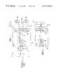
- FIG. 3is a block diagram illustrating in detail the high pass filter of FIGS. 1 and 2 according to an embodiment of the present invention.
- FIG. 1is a diagram of an Ethernet (IEEE 802.3) local area network 10 implemented in a home environment using twisted pair network media according to an embodiment of the present invention.
- the home environmentincludes a network termination basic access (NTBA) device 12 , configured for sending and receiving integrated services digital network (ISDN) signals to and from a public switch telephone network.
- the NTBA device 12is configured for outputting ISDN-type telephone signals onto a 4-wire S0 bus ( 14 ) having 2 wires for a send path and 2 wires for a receive path.
- the S0 bus 14may have a single termination, or multiple “taps” connected in parallel off the S0 bus 14 .
- a single terminationis shown as a private branch exchange 16 .
- the private branch exchange (PBX) 16is configured for coupling the telephone signal on the S0 bus 14 to a plurality of twisted pair wiring 18 , used to connect analog telephones 20 or computers via modem 22 according to a star topology.
- Conventional PBX systemssuch as PBX 16 ′ of FIG. 2, include a first connection 24 for connecting the S0 bus 14 from the NTBA 12 , an switch 26 and a plurality of analog port connections 28 .
- the switch 26is configured for switching analog telephone signals between the NTBA 12 via the S0 bus 14 and analog telephones 20 connected to the twisted pair 18 .
- the switch 26may interconnect two telephones 20 a and 20 b coupled via respective twisted pairs 18 , or may connect the telephones 20 to the public switched telephone network via the NTBA 12 .
- the switch 26supplies eight (8) pairs (A, B) of twisted wire to the connections 28 .
- Each pair of twisted wirehas a corresponding pair of connections (A, B) 28 in the PBX 16 and 16 ′.
- the telephone 20 ahas its pair of telephone wires connected to connections A 1 and B 1
- end station 22 ahas its twisted pair connected to connections A 2 and B 2
- telephone 20 bhas its corresponding twisted pair connected to connections A 3 , B 3 , etc.
- the switch 26is band limited to 4 kilohertz for the switching of analog telephone signals between the connections 28 .
- the switch 26would attenuate the high-frequency home network signals generated by the end stations 22 .
- a high-pass filter circuit (HPF) 30is added between the switch 26 and the connected twisted pair telephone lines 18 , enabling the higher-frequency network data signals (i.e., home network signals) transmitted by the end stations 22 a and 22 b to bypass the switch 26 .
- a computer networkmay be implemented in a customer premises having a star topology-based telephone network.
- the high-pass circuit 30rejects lower-frequency signals within the analog telephone signal band, enabling the switch to be bypassed for transmission of network data signals without interfering with the normal switch operations for analog telephone signals.
- the PBX 16includes a high pass circuit coupled between the switch 26 and the connections 28 .
- the actual connection of the high pass filter 30 in both FIGS. 1 and 2coupled corresponding lines of each twisted pair telephone wiring to form a high pass circuit, such that each of the twisted pair wiring 18 are connected in parallel.
- FIG. 2is a diagram illustrating a variation of the embodiment of FIG. 1, where the high pass filter 30 is connected to the twisted pair media 18 external to the PBX 16 ′.
- the PBX 16 of FIG. 1is considered an improvement over the conventional PBX system 16 ′, whereas the arrangement of FIG. 2 is advantageous for upgrading or retrofiting existing customer premises systems that already have the conventional PBX 16 ′ installed.
- FIG. 3is a block diagram illustrating in detail the high pass filter 30 according to an embodiment of the present invention.
- the high pass filter 30includes connectors 40 , 42 , 44 , and 46 for connecting the first and second pairs 18 of telephone wire.
- connections 40 , 42 , 44 , and 46are coupled to connectors A 1 , B 1 , A 2 , and B 2 of connector 28 , respectively.
- the connectors 40 and 42establish a high pass filter across the twisted pair with corresponding to end station 20 a
- the connectors 44 and 46establish a high pass filter connection for the twisted pair wire connecting the end station 22 a.
- a high pass filteris formed across the connections A 1 and B 1 based on the capacitors C 1 and C 2 , and the inductance element 50 , shown as a choke.
- the choke 50includes a first winding 52 coupled to nodes A and B.
- the nodes A and B of high pass filter 30are capacitively coupled to a corresponding one of the telephone lines for each twisted pair.
- the node Ais capacitively coupled to terminal connections A 1 , A 2 , A 3 , . . . A 8 and node B is capacitively coupled to connections B 1 , B 2 , B 3 . . . B 8 .
- the first winding 52 of choke 50provides an inductive load across all the associated twisted pair telephone wires 18 , resulting in a parallel connection of the twisted pair wires 18 for transmission of network data signals at frequency substantially higher than the analog telephone signals.
- the choke 50also includes a second winding 54 that is galvanically isolated from the first winding. Since the second winding 54 is inductively coupled to the first winding 52 via the core 56 , the inductive coupling generates a copy of the transmitted network data signals onto the second winding 54 . Hence, the terminal ends of the second winding 54 may be used for additional monitoring of the transmitted network data signals passing through the first winding 52 without adding any additional distortion to the network medium.
- the capacitance between A and B terminalsmay be substantially high as to cause a short circuit for high frequency signals between terminals A and B.
- the high pass filter circuit 30further includes a second high-impedance device 60 , labeled as choke 1 , which is inserted in between the terminal ends 40 and 42 and the actual terminal connections A 1 and B 1 of connector 28 .
- the high inductance device 60compensates for the high capacitance within the switch 26 , eliminating the possibility of a short circuit for the high frequency network signals.
- a high pass filteris added to a PBX configured for switching analog telephone signals, enabling implementation of a parallel-type shared medium local area network in a customer premises telephone system having a start-wiring topology.
- home networking technologiesmay be implemented in residential premises using analog PBX switches with minimal modifications.
Landscapes
- Physics & Mathematics (AREA)
- Astronomy & Astrophysics (AREA)
- General Physics & Mathematics (AREA)
- Engineering & Computer Science (AREA)
- Computer Networks & Wireless Communication (AREA)
- Sub-Exchange Stations And Push- Button Telephones (AREA)
- Telephonic Communication Services (AREA)
- Small-Scale Networks (AREA)
Abstract
Description
Claims (18)
Priority Applications (10)
| Application Number | Priority Date | Filing Date | Title |
|---|---|---|---|
| US09/302,294US6473495B1 (en) | 1999-04-15 | 1999-04-30 | Apparatus and method for coupling analog subscriber lines connected to a private branch exchange for transmission of network data signals in a home network |
| JP2000613122AJP4373613B2 (en) | 1999-04-15 | 1999-08-25 | Apparatus and method for combining analog subscriber lines in a home network |
| DE29918150UDE29918150U1 (en) | 1999-04-15 | 1999-08-25 | Computer network device |
| PCT/US1999/019761WO2000064105A1 (en) | 1999-04-15 | 1999-08-25 | Apparatus and method for coupling analog subscriber lines in a home network |
| AT99945288TATE284103T1 (en) | 1999-04-15 | 1999-08-25 | METHOD AND DEVICE FOR COUPLING ANALOGUE SUBSCRIBE LINES IN A HOUSE NETWORK |
| AU57916/99AAU759224B2 (en) | 1999-04-15 | 1999-08-25 | Apparatus and method for coupling analog subscriber lines in a home network |
| CNB998166472ACN1144424C (en) | 1999-04-15 | 1999-08-25 | Device and method for coupling analog subscriber lines in a home network |
| BR9917258-5ABR9917258A (en) | 1999-04-15 | 1999-08-25 | Method for controlling data transmission between network stations connected to a telephone line medium |
| EP99945288AEP1169821B1 (en) | 1999-04-15 | 1999-08-25 | Apparatus and method for coupling analog subscriber lines in a home network |
| DE69922416TDE69922416T2 (en) | 1999-04-15 | 1999-08-25 | METHOD AND DEVICE THE COUPLING OF ANALOG PARTICULAR LINES IN A HOME NETWORK |
Applications Claiming Priority (2)
| Application Number | Priority Date | Filing Date | Title |
|---|---|---|---|
| US12935599P | 1999-04-15 | 1999-04-15 | |
| US09/302,294US6473495B1 (en) | 1999-04-15 | 1999-04-30 | Apparatus and method for coupling analog subscriber lines connected to a private branch exchange for transmission of network data signals in a home network |
Publications (1)
| Publication Number | Publication Date |
|---|---|
| US6473495B1true US6473495B1 (en) | 2002-10-29 |
Family
ID=26827489
Family Applications (1)
| Application Number | Title | Priority Date | Filing Date |
|---|---|---|---|
| US09/302,294Expired - Fee RelatedUS6473495B1 (en) | 1999-04-15 | 1999-04-30 | Apparatus and method for coupling analog subscriber lines connected to a private branch exchange for transmission of network data signals in a home network |
Country Status (9)
| Country | Link |
|---|---|
| US (1) | US6473495B1 (en) |
| EP (1) | EP1169821B1 (en) |
| JP (1) | JP4373613B2 (en) |
| CN (1) | CN1144424C (en) |
| AT (1) | ATE284103T1 (en) |
| AU (1) | AU759224B2 (en) |
| BR (1) | BR9917258A (en) |
| DE (2) | DE29918150U1 (en) |
| WO (1) | WO2000064105A1 (en) |
Cited By (25)
| Publication number | Priority date | Publication date | Assignee | Title |
|---|---|---|---|---|
| US20020071532A1 (en)* | 2000-07-19 | 2002-06-13 | Thomas Bebko | Private branch exchange for interconnecting data networks |
| WO2003067867A1 (en)* | 2002-02-06 | 2003-08-14 | Bellsouth Intellectual Property Corporation | Hpna network bridge |
| US6836546B1 (en)* | 1999-11-03 | 2004-12-28 | Advanced Micro Devices, Inc. | Apparatus and method of coupling home network signals between an analog phone line and a digital bus |
| US20050105718A1 (en)* | 2002-03-20 | 2005-05-19 | Sennheiser Communications A/S | Active audio compressing in telecommunication |
| US20070178868A1 (en)* | 2006-01-30 | 2007-08-02 | Research In Motion Limited | Telephone system having reduced sensitivity to RF interference and related methods |
| US7274688B2 (en) | 2000-04-18 | 2007-09-25 | Serconet Ltd. | Telephone communication system over a single telephone line |
| US7305006B1 (en)* | 2001-08-24 | 2007-12-04 | Westell Technologies, Inc. | System for allowing a single device to share multiple transmission lines |
| US7317793B2 (en) | 2003-01-30 | 2008-01-08 | Serconet Ltd | Method and system for providing DC power on local telephone lines |
| US7436842B2 (en) | 2001-10-11 | 2008-10-14 | Serconet Ltd. | Outlet with analog signal adapter, a method for use thereof and a network using said outlet |
| US7483524B2 (en) | 1999-07-20 | 2009-01-27 | Serconet, Ltd | Network for telephony and data communication |
| US7522714B2 (en) | 2000-03-20 | 2009-04-21 | Serconet Ltd. | Telephone outlet for implementing a local area network over telephone lines and a local area network using such outlets |
| US7542554B2 (en) | 2001-07-05 | 2009-06-02 | Serconet, Ltd | Telephone outlet with packet telephony adapter, and a network using same |
| US7587001B2 (en) | 2006-01-11 | 2009-09-08 | Serconet Ltd. | Apparatus and method for frequency shifting of a wireless signal and systems using frequency shifting |
| US7633966B2 (en) | 2000-04-19 | 2009-12-15 | Mosaid Technologies Incorporated | Network combining wired and non-wired segments |
| US7686653B2 (en) | 2003-09-07 | 2010-03-30 | Mosaid Technologies Incorporated | Modular outlet |
| US7873058B2 (en) | 2004-11-08 | 2011-01-18 | Mosaid Technologies Incorporated | Outlet with analog signal adapter, a method for use thereof and a network using said outlet |
| US8175649B2 (en) | 2008-06-20 | 2012-05-08 | Corning Mobileaccess Ltd | Method and system for real time control of an active antenna over a distributed antenna system |
| US8238328B2 (en) | 2003-03-13 | 2012-08-07 | Mosaid Technologies Incorporated | Telephone system having multiple distinct sources and accessories therefor |
| US8270430B2 (en) | 1998-07-28 | 2012-09-18 | Mosaid Technologies Incorporated | Local area network of serial intelligent cells |
| US8325759B2 (en) | 2004-05-06 | 2012-12-04 | Corning Mobileaccess Ltd | System and method for carrying a wireless based signal over wiring |
| US8594133B2 (en) | 2007-10-22 | 2013-11-26 | Corning Mobileaccess Ltd. | Communication system using low bandwidth wires |
| US8897215B2 (en) | 2009-02-08 | 2014-11-25 | Corning Optical Communications Wireless Ltd | Communication system using cables carrying ethernet signals |
| US9184960B1 (en) | 2014-09-25 | 2015-11-10 | Corning Optical Communications Wireless Ltd | Frequency shifting a communications signal(s) in a multi-frequency distributed antenna system (DAS) to avoid or reduce frequency interference |
| US9338823B2 (en) | 2012-03-23 | 2016-05-10 | Corning Optical Communications Wireless Ltd | Radio-frequency integrated circuit (RFIC) chip(s) for providing distributed antenna system functionalities, and related components, systems, and methods |
| US10986164B2 (en) | 2004-01-13 | 2021-04-20 | May Patents Ltd. | Information device |
Families Citing this family (2)
| Publication number | Priority date | Publication date | Assignee | Title |
|---|---|---|---|---|
| CA2559133C (en) | 2006-09-08 | 2011-10-25 | Bce Inc | Apparatus and system for controlling signal filtering |
| FR2941119B1 (en)* | 2009-01-09 | 2017-12-22 | Avivox | HIGH VOLUME COMMUNICATION SYSTEM THROUGH A PRIVATE TELECOMMUNICATION NETWORK |
Citations (6)
| Publication number | Priority date | Publication date | Assignee | Title |
|---|---|---|---|---|
| US4785448A (en)* | 1987-02-25 | 1988-11-15 | Reichert Andrew R | System for communicating digital data on a standard office telephone system |
| US4918688A (en)* | 1986-10-31 | 1990-04-17 | Convergent Technologies, Inc. | Method and apparatus for coupling computer work stations |
| WO1998002985A1 (en) | 1996-07-12 | 1998-01-22 | Inline Connection Corporation | Digital communication system for apartment buildings and similar structures using existing telephone wires |
| US5841841A (en)* | 1995-03-16 | 1998-11-24 | Telecommunications Research Laboratories | Networking computers via shared use of voice telephone lines |
| US6115466A (en)* | 1998-03-12 | 2000-09-05 | Westell Technologies, Inc. | Subscriber line system having a dual-mode filter for voice communications over a telephone line |
| US6243446B1 (en)* | 1997-03-11 | 2001-06-05 | Inline Connections Corporation | Distributed splitter for data transmission over twisted wire pairs |
- 1999
- 1999-04-30USUS09/302,294patent/US6473495B1/ennot_activeExpired - Fee Related
- 1999-08-25DEDE29918150Upatent/DE29918150U1/ennot_activeExpired - Lifetime
- 1999-08-25DEDE69922416Tpatent/DE69922416T2/ennot_activeExpired - Lifetime
- 1999-08-25EPEP99945288Apatent/EP1169821B1/ennot_activeExpired - Lifetime
- 1999-08-25BRBR9917258-5Apatent/BR9917258A/ennot_activeIP Right Cessation
- 1999-08-25ATAT99945288Tpatent/ATE284103T1/ennot_activeIP Right Cessation
- 1999-08-25CNCNB998166472Apatent/CN1144424C/ennot_activeExpired - Fee Related
- 1999-08-25WOPCT/US1999/019761patent/WO2000064105A1/enactiveIP Right Grant
- 1999-08-25JPJP2000613122Apatent/JP4373613B2/ennot_activeExpired - Fee Related
- 1999-08-25AUAU57916/99Apatent/AU759224B2/ennot_activeCeased
Patent Citations (6)
| Publication number | Priority date | Publication date | Assignee | Title |
|---|---|---|---|---|
| US4918688A (en)* | 1986-10-31 | 1990-04-17 | Convergent Technologies, Inc. | Method and apparatus for coupling computer work stations |
| US4785448A (en)* | 1987-02-25 | 1988-11-15 | Reichert Andrew R | System for communicating digital data on a standard office telephone system |
| US5841841A (en)* | 1995-03-16 | 1998-11-24 | Telecommunications Research Laboratories | Networking computers via shared use of voice telephone lines |
| WO1998002985A1 (en) | 1996-07-12 | 1998-01-22 | Inline Connection Corporation | Digital communication system for apartment buildings and similar structures using existing telephone wires |
| US6243446B1 (en)* | 1997-03-11 | 2001-06-05 | Inline Connections Corporation | Distributed splitter for data transmission over twisted wire pairs |
| US6115466A (en)* | 1998-03-12 | 2000-09-05 | Westell Technologies, Inc. | Subscriber line system having a dual-mode filter for voice communications over a telephone line |
Cited By (83)
| Publication number | Priority date | Publication date | Assignee | Title |
|---|---|---|---|---|
| US8885659B2 (en) | 1998-07-28 | 2014-11-11 | Conversant Intellectual Property Management Incorporated | Local area network of serial intelligent cells |
| US8270430B2 (en) | 1998-07-28 | 2012-09-18 | Mosaid Technologies Incorporated | Local area network of serial intelligent cells |
| US8325636B2 (en) | 1998-07-28 | 2012-12-04 | Mosaid Technologies Incorporated | Local area network of serial intelligent cells |
| US8867523B2 (en) | 1998-07-28 | 2014-10-21 | Conversant Intellectual Property Management Incorporated | Local area network of serial intelligent cells |
| US8908673B2 (en) | 1998-07-28 | 2014-12-09 | Conversant Intellectual Property Management Incorporated | Local area network of serial intelligent cells |
| US8885660B2 (en) | 1998-07-28 | 2014-11-11 | Conversant Intellectual Property Management Incorporated | Local area network of serial intelligent cells |
| US7483524B2 (en) | 1999-07-20 | 2009-01-27 | Serconet, Ltd | Network for telephony and data communication |
| US8351582B2 (en) | 1999-07-20 | 2013-01-08 | Mosaid Technologies Incorporated | Network for telephony and data communication |
| US7522713B2 (en) | 1999-07-20 | 2009-04-21 | Serconet, Ltd. | Network for telephony and data communication |
| US8929523B2 (en) | 1999-07-20 | 2015-01-06 | Conversant Intellectual Property Management Inc. | Network for telephony and data communication |
| US7492875B2 (en) | 1999-07-20 | 2009-02-17 | Serconet, Ltd. | Network for telephony and data communication |
| US6836546B1 (en)* | 1999-11-03 | 2004-12-28 | Advanced Micro Devices, Inc. | Apparatus and method of coupling home network signals between an analog phone line and a digital bus |
| US8855277B2 (en) | 2000-03-20 | 2014-10-07 | Conversant Intellectual Property Managment Incorporated | Telephone outlet for implementing a local area network over telephone lines and a local area network using such outlets |
| US7715534B2 (en) | 2000-03-20 | 2010-05-11 | Mosaid Technologies Incorporated | Telephone outlet for implementing a local area network over telephone lines and a local area network using such outlets |
| US8363797B2 (en) | 2000-03-20 | 2013-01-29 | Mosaid Technologies Incorporated | Telephone outlet for implementing a local area network over telephone lines and a local area network using such outlets |
| US7522714B2 (en) | 2000-03-20 | 2009-04-21 | Serconet Ltd. | Telephone outlet for implementing a local area network over telephone lines and a local area network using such outlets |
| US7466722B2 (en) | 2000-04-18 | 2008-12-16 | Serconet Ltd | Telephone communication system over a single telephone line |
| US7397791B2 (en) | 2000-04-18 | 2008-07-08 | Serconet, Ltd. | Telephone communication system over a single telephone line |
| US7274688B2 (en) | 2000-04-18 | 2007-09-25 | Serconet Ltd. | Telephone communication system over a single telephone line |
| US8223800B2 (en) | 2000-04-18 | 2012-07-17 | Mosaid Technologies Incorporated | Telephone communication system over a single telephone line |
| US8000349B2 (en) | 2000-04-18 | 2011-08-16 | Mosaid Technologies Incorporated | Telephone communication system over a single telephone line |
| US7593394B2 (en) | 2000-04-18 | 2009-09-22 | Mosaid Technologies Incorporated | Telephone communication system over a single telephone line |
| US8559422B2 (en) | 2000-04-18 | 2013-10-15 | Mosaid Technologies Incorporated | Telephone communication system over a single telephone line |
| US7633966B2 (en) | 2000-04-19 | 2009-12-15 | Mosaid Technologies Incorporated | Network combining wired and non-wired segments |
| US8867506B2 (en) | 2000-04-19 | 2014-10-21 | Conversant Intellectual Property Management Incorporated | Network combining wired and non-wired segments |
| US8873575B2 (en) | 2000-04-19 | 2014-10-28 | Conversant Intellectual Property Management Incorporated | Network combining wired and non-wired segments |
| US8848725B2 (en) | 2000-04-19 | 2014-09-30 | Conversant Intellectual Property Management Incorporated | Network combining wired and non-wired segments |
| US8873586B2 (en) | 2000-04-19 | 2014-10-28 | Conversant Intellectual Property Management Incorporated | Network combining wired and non-wired segments |
| US8982904B2 (en) | 2000-04-19 | 2015-03-17 | Conversant Intellectual Property Management Inc. | Network combining wired and non-wired segments |
| US20020071532A1 (en)* | 2000-07-19 | 2002-06-13 | Thomas Bebko | Private branch exchange for interconnecting data networks |
| US7542554B2 (en) | 2001-07-05 | 2009-06-02 | Serconet, Ltd | Telephone outlet with packet telephony adapter, and a network using same |
| US8472593B2 (en) | 2001-07-05 | 2013-06-25 | Mosaid Technologies Incorporated | Telephone outlet with packet telephony adaptor, and a network using same |
| US7680255B2 (en) | 2001-07-05 | 2010-03-16 | Mosaid Technologies Incorporated | Telephone outlet with packet telephony adaptor, and a network using same |
| US8761186B2 (en) | 2001-07-05 | 2014-06-24 | Conversant Intellectual Property Management Incorporated | Telephone outlet with packet telephony adapter, and a network using same |
| US7769030B2 (en) | 2001-07-05 | 2010-08-03 | Mosaid Technologies Incorporated | Telephone outlet with packet telephony adapter, and a network using same |
| US7305006B1 (en)* | 2001-08-24 | 2007-12-04 | Westell Technologies, Inc. | System for allowing a single device to share multiple transmission lines |
| US7453895B2 (en) | 2001-10-11 | 2008-11-18 | Serconet Ltd | Outlet with analog signal adapter, a method for use thereof and a network using said outlet |
| US7953071B2 (en) | 2001-10-11 | 2011-05-31 | Mosaid Technologies Incorporated | Outlet with analog signal adapter, a method for use thereof and a network using said outlet |
| US7436842B2 (en) | 2001-10-11 | 2008-10-14 | Serconet Ltd. | Outlet with analog signal adapter, a method for use thereof and a network using said outlet |
| US7889720B2 (en) | 2001-10-11 | 2011-02-15 | Mosaid Technologies Incorporated | Outlet with analog signal adapter, a method for use thereof and a network using said outlet |
| US7860084B2 (en) | 2001-10-11 | 2010-12-28 | Mosaid Technologies Incorporated | Outlet with analog signal adapter, a method for use thereof and a network using said outlet |
| WO2003067867A1 (en)* | 2002-02-06 | 2003-08-14 | Bellsouth Intellectual Property Corporation | Hpna network bridge |
| US7231037B2 (en) | 2002-03-20 | 2007-06-12 | Sennheiser Communications A/S | Active audio compressing in telecommunication |
| US20050105718A1 (en)* | 2002-03-20 | 2005-05-19 | Sennheiser Communications A/S | Active audio compressing in telecommunication |
| USRE42093E1 (en)* | 2002-03-20 | 2011-02-01 | Sennheiser Communications A/S | Active audio compressing in telecommunication |
| US8787562B2 (en) | 2003-01-30 | 2014-07-22 | Conversant Intellectual Property Management Inc. | Method and system for providing DC power on local telephone lines |
| US7317793B2 (en) | 2003-01-30 | 2008-01-08 | Serconet Ltd | Method and system for providing DC power on local telephone lines |
| US8107618B2 (en) | 2003-01-30 | 2012-01-31 | Mosaid Technologies Incorporated | Method and system for providing DC power on local telephone lines |
| US7702095B2 (en) | 2003-01-30 | 2010-04-20 | Mosaid Technologies Incorporated | Method and system for providing DC power on local telephone lines |
| US8238328B2 (en) | 2003-03-13 | 2012-08-07 | Mosaid Technologies Incorporated | Telephone system having multiple distinct sources and accessories therefor |
| US7867035B2 (en) | 2003-07-09 | 2011-01-11 | Mosaid Technologies Incorporated | Modular outlet |
| US7686653B2 (en) | 2003-09-07 | 2010-03-30 | Mosaid Technologies Incorporated | Modular outlet |
| US8360810B2 (en) | 2003-09-07 | 2013-01-29 | Mosaid Technologies Incorporated | Modular outlet |
| US8235755B2 (en) | 2003-09-07 | 2012-08-07 | Mosaid Technologies Incorporated | Modular outlet |
| US8092258B2 (en) | 2003-09-07 | 2012-01-10 | Mosaid Technologies Incorporated | Modular outlet |
| US8591264B2 (en) | 2003-09-07 | 2013-11-26 | Mosaid Technologies Incorporated | Modular outlet |
| US10986165B2 (en) | 2004-01-13 | 2021-04-20 | May Patents Ltd. | Information device |
| US11095708B2 (en) | 2004-01-13 | 2021-08-17 | May Patents Ltd. | Information device |
| US10986164B2 (en) | 2004-01-13 | 2021-04-20 | May Patents Ltd. | Information device |
| US11032353B2 (en) | 2004-01-13 | 2021-06-08 | May Patents Ltd. | Information device |
| US8325759B2 (en) | 2004-05-06 | 2012-12-04 | Corning Mobileaccess Ltd | System and method for carrying a wireless based signal over wiring |
| US7873058B2 (en) | 2004-11-08 | 2011-01-18 | Mosaid Technologies Incorporated | Outlet with analog signal adapter, a method for use thereof and a network using said outlet |
| US7587001B2 (en) | 2006-01-11 | 2009-09-08 | Serconet Ltd. | Apparatus and method for frequency shifting of a wireless signal and systems using frequency shifting |
| US7813451B2 (en) | 2006-01-11 | 2010-10-12 | Mobileaccess Networks Ltd. | Apparatus and method for frequency shifting of a wireless signal and systems using frequency shifting |
| US8184681B2 (en) | 2006-01-11 | 2012-05-22 | Corning Mobileaccess Ltd | Apparatus and method for frequency shifting of a wireless signal and systems using frequency shifting |
| US7480523B2 (en) | 2006-01-30 | 2009-01-20 | Reseach In Motion Limited | Telephone system having reduced sensitivity to RF interference and related methods |
| US20070178868A1 (en)* | 2006-01-30 | 2007-08-02 | Research In Motion Limited | Telephone system having reduced sensitivity to RF interference and related methods |
| US8086286B2 (en) | 2006-01-30 | 2011-12-27 | Research In Motion Limited | Telephone system having reduced sensitivity to RF interference and related methods |
| US7869841B2 (en) | 2006-01-30 | 2011-01-11 | Research In Motion Limited | Telephone system having reduced sensitivity to RF interference and related methods |
| US20110092258A1 (en)* | 2006-01-30 | 2011-04-21 | Research In Motion Limited | Telephone system having reduced sensitivity to rf interference and related methods |
| US20090080643A1 (en)* | 2006-01-30 | 2009-03-26 | Research In Motion Limited | Telephone System Having Reduced Sensitivity To RF Interference And Related Methods |
| US8417299B2 (en) | 2006-01-30 | 2013-04-09 | Research In Motion Limited | Telephone system having reduced sensitivity to RF interference and related methods |
| US8594133B2 (en) | 2007-10-22 | 2013-11-26 | Corning Mobileaccess Ltd. | Communication system using low bandwidth wires |
| US9813229B2 (en) | 2007-10-22 | 2017-11-07 | Corning Optical Communications Wireless Ltd | Communication system using low bandwidth wires |
| US9549301B2 (en) | 2007-12-17 | 2017-01-17 | Corning Optical Communications Wireless Ltd | Method and system for real time control of an active antenna over a distributed antenna system |
| US8175649B2 (en) | 2008-06-20 | 2012-05-08 | Corning Mobileaccess Ltd | Method and system for real time control of an active antenna over a distributed antenna system |
| US8897215B2 (en) | 2009-02-08 | 2014-11-25 | Corning Optical Communications Wireless Ltd | Communication system using cables carrying ethernet signals |
| US9338823B2 (en) | 2012-03-23 | 2016-05-10 | Corning Optical Communications Wireless Ltd | Radio-frequency integrated circuit (RFIC) chip(s) for providing distributed antenna system functionalities, and related components, systems, and methods |
| US9948329B2 (en) | 2012-03-23 | 2018-04-17 | Corning Optical Communications Wireless, LTD | Radio-frequency integrated circuit (RFIC) chip(s) for providing distributed antenna system functionalities, and related components, systems, and methods |
| US10141959B2 (en) | 2012-03-23 | 2018-11-27 | Corning Optical Communications Wireless Ltd | Radio-frequency integrated circuit (RFIC) chip(s) for providing distributed antenna system functionalities, and related components, systems, and methods |
| US9515855B2 (en) | 2014-09-25 | 2016-12-06 | Corning Optical Communications Wireless Ltd | Frequency shifting a communications signal(s) in a multi-frequency distributed antenna system (DAS) to avoid or reduce frequency interference |
| US9253003B1 (en) | 2014-09-25 | 2016-02-02 | Corning Optical Communications Wireless Ltd | Frequency shifting a communications signal(S) in a multi-frequency distributed antenna system (DAS) to avoid or reduce frequency interference |
| US9184960B1 (en) | 2014-09-25 | 2015-11-10 | Corning Optical Communications Wireless Ltd | Frequency shifting a communications signal(s) in a multi-frequency distributed antenna system (DAS) to avoid or reduce frequency interference |
Also Published As
| Publication number | Publication date |
|---|---|
| AU5791699A (en) | 2000-11-02 |
| DE29918150U1 (en) | 2000-03-30 |
| ATE284103T1 (en) | 2004-12-15 |
| EP1169821B1 (en) | 2004-12-01 |
| EP1169821A1 (en) | 2002-01-09 |
| CN1350737A (en) | 2002-05-22 |
| AU759224B2 (en) | 2003-04-10 |
| WO2000064105A1 (en) | 2000-10-26 |
| CN1144424C (en) | 2004-03-31 |
| DE69922416D1 (en) | 2005-01-05 |
| BR9917258A (en) | 2002-01-08 |
| DE69922416T2 (en) | 2005-12-22 |
| JP4373613B2 (en) | 2009-11-25 |
| JP2002542717A (en) | 2002-12-10 |
Similar Documents
| Publication | Publication Date | Title |
|---|---|---|
| US6473495B1 (en) | Apparatus and method for coupling analog subscriber lines connected to a private branch exchange for transmission of network data signals in a home network | |
| US6836546B1 (en) | Apparatus and method of coupling home network signals between an analog phone line and a digital bus | |
| US6522728B1 (en) | Apparatus and method of implementing a universal home network on a customer premises ISDN bus | |
| US6624745B1 (en) | Low pass filter for a universal home network on a customer premises european installation bus | |
| US7305006B1 (en) | System for allowing a single device to share multiple transmission lines | |
| US6377665B1 (en) | Apparatus and method of implementing a universal home network on a customer premises UPN telephone lines | |
| US6584079B1 (en) | Apparatus and method of implementing a home network by filtering ISDN-based signals within the customer premises | |
| US6393109B1 (en) | Apparatus and method of coupling home network signals between an analog phone line and a digital UPN line |
Legal Events
| Date | Code | Title | Description |
|---|---|---|---|
| AS | Assignment | Owner name:ADVANCED MICRO DEVICES, INC., CALIFORNIA Free format text:ASSIGNMENT OF ASSIGNORS INTEREST;ASSIGNOR:WILLER, BERND;REEL/FRAME:009930/0584 Effective date:19990430 | |
| FEPP | Fee payment procedure | Free format text:PAYOR NUMBER ASSIGNED (ORIGINAL EVENT CODE: ASPN); ENTITY STATUS OF PATENT OWNER: LARGE ENTITY | |
| FPAY | Fee payment | Year of fee payment:4 | |
| AS | Assignment | Owner name:GLOBALFOUNDRIES INC., CAYMAN ISLANDS Free format text:ASSIGNMENT OF ASSIGNORS INTEREST;ASSIGNOR:AMD TECHNOLOGIES HOLDINGS, INC.;REEL/FRAME:022764/0544 Effective date:20090302 Owner name:AMD TECHNOLOGIES HOLDINGS, INC., CALIFORNIA Free format text:ASSIGNMENT OF ASSIGNORS INTEREST;ASSIGNOR:ADVANCED MICRO DEVICES, INC.;REEL/FRAME:022764/0488 Effective date:20090302 | |
| FPAY | Fee payment | Year of fee payment:8 | |
| REMI | Maintenance fee reminder mailed | ||
| LAPS | Lapse for failure to pay maintenance fees | ||
| STCH | Information on status: patent discontinuation | Free format text:PATENT EXPIRED DUE TO NONPAYMENT OF MAINTENANCE FEES UNDER 37 CFR 1.362 | |
| FP | Lapsed due to failure to pay maintenance fee | Effective date:20141029 | |
| AS | Assignment | Owner name:GLOBALFOUNDRIES U.S. INC., NEW YORK Free format text:RELEASE BY SECURED PARTY;ASSIGNOR:WILMINGTON TRUST, NATIONAL ASSOCIATION;REEL/FRAME:056987/0001 Effective date:20201117 |