US6473487B1 - Method and apparatus for physical characteristics discrimination of objects using a limited view three dimensional reconstruction - Google Patents
Method and apparatus for physical characteristics discrimination of objects using a limited view three dimensional reconstructionDownload PDFInfo
- Publication number
- US6473487B1 US6473487B1US09/752,811US75281100AUS6473487B1US 6473487 B1US6473487 B1US 6473487B1US 75281100 AUS75281100 AUS 75281100AUS 6473487 B1US6473487 B1US 6473487B1
- Authority
- US
- United States
- Prior art keywords
- physical characteristic
- specified physical
- electromagnetic radiation
- sources
- explosives
- Prior art date
- Legal status (The legal status is an assumption and is not a legal conclusion. Google has not performed a legal analysis and makes no representation as to the accuracy of the status listed.)
- Expired - Lifetime
Links
- 238000000034methodMethods0.000titleclaimsabstractdescription55
- 230000005670electromagnetic radiationEffects0.000claimsabstractdescription45
- 239000002360explosiveSubstances0.000claimsdescription33
- 239000003814drugSubstances0.000claimsdescription12
- 229940079593drugDrugs0.000claimsdescription12
- 230000005855radiationEffects0.000claimsdescription9
- 238000003491arrayMethods0.000claims7
- 239000000463materialSubstances0.000description22
- 238000010586diagramMethods0.000description20
- 238000001514detection methodMethods0.000description12
- 230000008569processEffects0.000description11
- 239000011368organic materialSubstances0.000description6
- 238000002601radiographyMethods0.000description6
- 230000009977dual effectEffects0.000description5
- 238000003325tomographyMethods0.000description5
- 238000007689inspectionMethods0.000description4
- 230000008901benefitEffects0.000description3
- 230000007246mechanismEffects0.000description3
- 230000010355oscillationEffects0.000description3
- XEEYBQQBJWHFJM-UHFFFAOYSA-NIronChemical compound[Fe]XEEYBQQBJWHFJM-UHFFFAOYSA-N0.000description2
- 229910052782aluminiumInorganic materials0.000description2
- XAGFODPZIPBFFR-UHFFFAOYSA-NaluminiumChemical compound[Al]XAGFODPZIPBFFR-UHFFFAOYSA-N0.000description2
- 238000011161developmentMethods0.000description2
- 238000003384imaging methodMethods0.000description2
- 230000033001locomotionEffects0.000description2
- 238000005259measurementMethods0.000description2
- 230000000007visual effectEffects0.000description2
- 238000010521absorption reactionMethods0.000description1
- 238000013459approachMethods0.000description1
- 238000012790confirmationMethods0.000description1
- 230000007423decreaseEffects0.000description1
- 230000007812deficiencyEffects0.000description1
- 230000003111delayed effectEffects0.000description1
- 230000000694effectsEffects0.000description1
- 230000010006flightEffects0.000description1
- 239000011888foilSubstances0.000description1
- 229910052742ironInorganic materials0.000description1
- 229910052751metalInorganic materials0.000description1
- 239000002184metalSubstances0.000description1
- 239000007769metal materialSubstances0.000description1
- 150000002739metalsChemical class0.000description1
- 238000012986modificationMethods0.000description1
- 230000004048modificationEffects0.000description1
- 230000032258transportEffects0.000description1
Images


Classifications
- G—PHYSICS
- G01—MEASURING; TESTING
- G01V—GEOPHYSICS; GRAVITATIONAL MEASUREMENTS; DETECTING MASSES OR OBJECTS; TAGS
- G01V5/00—Prospecting or detecting by the use of ionising radiation, e.g. of natural or induced radioactivity
- G01V5/20—Detecting prohibited goods, e.g. weapons, explosives, hazardous substances, contraband or smuggled objects
- G01V5/22—Active interrogation, i.e. by irradiating objects or goods using external radiation sources, e.g. using gamma rays or cosmic rays
- G01V5/226—Active interrogation, i.e. by irradiating objects or goods using external radiation sources, e.g. using gamma rays or cosmic rays using tomography
- G—PHYSICS
- G01—MEASURING; TESTING
- G01N—INVESTIGATING OR ANALYSING MATERIALS BY DETERMINING THEIR CHEMICAL OR PHYSICAL PROPERTIES
- G01N23/00—Investigating or analysing materials by the use of wave or particle radiation, e.g. X-rays or neutrons, not covered by groups G01N3/00 – G01N17/00, G01N21/00 or G01N22/00
- G01N23/02—Investigating or analysing materials by the use of wave or particle radiation, e.g. X-rays or neutrons, not covered by groups G01N3/00 – G01N17/00, G01N21/00 or G01N22/00 by transmitting the radiation through the material
- G01N23/04—Investigating or analysing materials by the use of wave or particle radiation, e.g. X-rays or neutrons, not covered by groups G01N3/00 – G01N17/00, G01N21/00 or G01N22/00 by transmitting the radiation through the material and forming images of the material
Definitions
- the present inventionrelates to the discrimination of physical characteristics of objects. More particularly, the present invention relates to a scanning system used to detect explosives or drugs and other items in baggage using a limited view three-dimensional reconstruction.
- Projection radiographyhas long been used for detection of metallic contraband in baggage.
- X-raysmay be used in projection radiography to measure the Compton scattering effects and photoelectric absorption to determine the number of electrons and the effective atomic number, respectively, of an object.
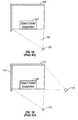
- FIG. 1 AAn example of a conventional projection radiography system is shown in FIG. 1 A.
- the conventional projection radiography systemincludes an X-ray tube source 102 , mounted in a suitable housing, to emit X-ray radiation toward an object 104 under inspection.
- a beam 106passes through object 104 and hit a conventional X-ray screen 108 of suitable phosphorescent material.
- Object 104is supported on a conveyor belt (not shown) that moves successive portions of the object through beam 106 such that successive slices of the object are scanned by beam 106 .
- a photo-detector array(not shown) that may comprise a linear array of photo-diodes (not shown) positioned coextensively beneath screen 108 .
- screen 108emits light in accordance with the energy and number of X-ray photons, which depend upon the characteristics of the portion of object 104 through which the X-ray ray photons pass.
- the photo-diodesreceive light generated by contiguous portions of screen 108 , and each photo-diode generates an electrical charge in accordance with the intensity of the light received thereby.
- the conventional system described aboveis effective in detecting materials that have a high radiographic contrast, such as metallic objects.
- organic materials that have a low radiographic contrastsuch as explosives, drugs, etc., are more difficult to detect with the conventional system.
- organic materialsdo not necessarily have a regular shape that would otherwise aid identification.
- Dual energy detection systemshave been developed which can detect organic materials.
- two X-ray beams having characteristically different photon energiesare used.
- organic materialstend to transmit approximately the same amount of high energy and low energy X-rays.
- Metalstransmit different amount of high energy and low energy X-ray. The amount of organic material present can therefore be determined.
- FIG. 1BOther dual energy detection systems, as illustrated in FIG. 1B, use two X-ray sources 110 and 112 positioned at distinct locations around object 104 . For each x-ray source, there exist a corresponding detector system 111 and 113 . The fan shape x-ray projection of both first and second sources intersects at object 104 . By capturing different views of the projected image of object 104 , an algorithm can be used to reconstruct a three-dimensional image of the object.
- the only characteristics that can be determinedare line of sight characteristics, such as the projected number of electrons and the effective atomic number along the line of sight through the object.
- line of sight characteristicssuch as the projected number of electrons and the effective atomic number along the line of sight through the object.
- a particular high measurement of N electrons/cm 2 along the line of sightcould be created by either a very thin object of high density or by a relatively thick object of low density.
- a measurement of an effective atomic number along the line of sight appropriate to aluminumcould be caused by a plate of aluminum or by a slab of explosives coupled with a thin foil of iron.
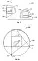
- FIG. 1Cillustrates the problem with projection imaging.
- a baggage scanning systemhas two x-ray sources 110 and 112 .
- An enclosure 114contains object 104 to be examined.
- Object 104is, for example, a parcel or a piece of luggage containing several thin sheets of explosives 116 and 118 .
- sheet of explosives 116is lined up to a very small angle relative to the X-ray beam as the position of x-ray source 112 , its density projection spreads out so that it is overwhelmed by clutters of other objects (not shown) in object 104 .
- Sheet explosive 116can only be resolved by x-ray source 112 .
- sheet explosive 118cannot be resolved by either source.
- projection imaging aloneis reliable to detect sheet explosives.
- Conventional computerized tomographycan overcome the problems described above associated with conventional projection radiography using both single and dual energy X-rays. That is, the three-dimensional nature of the reconstructed image generated by computerized tomography removes many of the problems associated with projection radiography and permits an absolute determination of electron densities and atomic numbers.
- conventional computerized tomographyrequires many views over 180 degrees of rotation about the object being scanned in order to generate a high quality reconstructed image. That is, for each cross-sectional view or slice of the object, the X-ray source must be positioned at a relatively large number of locations about the object and at each location the object is exposed and a projection (i.e., a shadow of the object) of the object is measured.
- Conventional computerized tomographyis therefore expensive, time consuming, and requires physically large and expensive hardware. Such equipment can cost $500,000 to $1,000,000 or more per unit.
- a method and apparatus for determining a specified physical characteristic in an objectexposes the object to at least two angularly fixed sources of electromagnetic radiation to create projected images of the object.
- the sourcesare rotationally scanned about the object so as to oscillate in an angular range about the object.
- the sourcesare relatively stationary to one another.
- a three dimensional reconstructed image of the object based on the projected images of the objectis created and examined for a specified physical characteristic in the object.
- FIG. 1Ais a schematic diagram of a side view of a conventional projection radiographic system having one x-ray source.
- FIG. 1Bis a schematic diagram of a side view of a conventional projection X-ray device having two x-ray sources and two detector systems.
- FIG. 1Cis a schematic diagram of a side view of a conventional projection X-ray device with two x-ray sources and two detector systems examining a parcel containing several thin explosive sheets.
- FIG. 1Dis a schematic diagram of a side view of a conventional computerized tomography scanner.
- FIG. 2is a schematic diagram of a side view of a projection radiographic system in accordance with one aspect of the present invention.
- FIG. 3Ais a schematic diagram of a side view of a projection radiographic system illustrating an example of a position of the X-ray sources in accordance with one aspect of the present invention.
- FIG. 3Bis a schematic diagram of a side view of a projection radiographic system illustrating another example of a position of the X-ray sources in accordance with one aspect of the present invention.
- FIG. 4Ais a schematic diagram of a side view of a projection radiographic system illustrating an example of a detection range based on the projected images of the object in accordance with one aspect of the present invention.
- FIG. 4Bis a schematic diagram of a side view of a projection radiographic system illustrating another example of a detection range based on the projected images of the object in accordance with one aspect of the present invention.
- FIG. 5is a schematic of a top view of a projection radiographic system in accordance with one aspect of the present invention.
- FIG. 6is a flow diagram of an overview of the process in accordance with one aspect of the present invention.
- FIG. 7is a flow diagram of the initialization process in accordance with one aspect of the present invention.
- FIG. 8is a flow diagram of the scanning process in accordance with one aspect of the present invention.
- FIG. 9is a flow diagram of the display process in accordance with one aspect of the present invention.
- Embodiments of the present inventionare described herein in the context of a method and apparatus for physical characteristics discrimination of objects using a limited view three-dimensional reconstruction. Those of ordinary skill in the art will realize that the following detailed description of the present invention is illustrative only and is not intended to be in any way limiting. Other embodiments of the present invention will readily suggest themselves to such skilled persons having the benefit of this disclosure. Reference will now be made in detail to implementations of the present invention as illustrated in the accompanying drawings. The same reference indicators will be used throughout the drawings and the following detailed description to refer to the same or like parts.
- FIG. 2is a schematic diagram of a side view of a projection radiographic system in accordance with one aspect of the present invention.
- a projection radiographic system 200 having a physical boundary, such as an inspection tunnel 202is used for determining a specified physical characteristic in an object 204 placed therein.
- Object 204may be a parcel, or a piece of luggage, or any object which may fit into the physical boundary of projection radiographic system 200 .
- Object 204may lay flat or upright on a moving mechanism, such as a conveyor belt, that transports object 204 through projection radiographic system 200 .
- Object 204contains, for example, an organic or metallic material 206 such as contraband comprising thin sheets of explosives or thin sheets of drugs.
- At least two sources of electromagnetic radiationsuch as x-ray sources 208 and 210 , expose object 204 and material 206 to create projected images on screens 212 and 214 .
- Some specified or predetermined physical characteristic of material 206 within object 204may be, for example, the density of an explosive, the Z number of explosive, or the shape of the contraband with respect to its density as x-ray sources 208 and 210 move around material 206 .
- Both x-ray sources 208 and 210may be located at different positions around object 204 to create several views of the projected images of object 204 and material 206 .
- Sources 208 and 210are relatively stationary to each other so that their respective projected images stay fixed in relation to each other.
- a three dimensional image of material 206 within object 204is created by generating a contiguous series of slices of object 204 .
- the three dimensional imageis preferably a representation of the density of object 204 in units of grams/cm 3 or a material type in terms of a Z-number.
- Each sliceis a reconstructed cross-sectional view of object 204 generated from the two view X-ray projections 212 and 214 taken at cross-section.
- X-ray sources 208 and 210emit a fan shaped beams of X-rays 216 and 218 respectively which are transmitted through object 204 to create a two-dimensional projected image that is detected by two array of sensors, such as photodetectors behind screen 212 and 214 .
- the screenspreferably include a large number of sensors uniformly distributed along a line that is aligned with fan shaped beam 216 and 218 . There may be one screen for each x-ray source.
- FIGS. 3A and 3Billustrate schematic diagrams of a projection radiographic system illustrating examples of positions of X-ray sources in accordance with one aspect of the present invention.
- a projection radiographic system 300has a first x-ray source 302 positioned at point A and a second x-ray source 304 positioned at point A′.
- Both X-ray sources 302 and 304are affixed to and from a part of a rotor 305 which rotates within a limited range around an object 306 in an inspection tunnel 307 so that X-ray sources 302 and 304 are moved to positions B and B′ as illustrated in FIG. 3 B.
- X-ray source 302may thus oscillate about object 306 between position A and A′
- X-ray source 304may thus oscillate about object 306 between position B and B′.
- the limited range of movement of electromagnetic sources around an objectdepends on the number of electromagnetic sources. For example, in a projection radiographic system having two electromagnetic sources, such as the one illustrated in FIGS. 3A and 3B, the full limited range of the rotation angle of the x-ray sources would be 90 degrees so that all possible locations for explosives in an object are examined.
- sources 302 and 304 along with their respective sensorsoscillate back and forth within their respective limited range.
- the total combined limited range of both x-ray sourcesshould equal 180 degrees for optimal detection range.
- the projected viewsstay in fixed relation to each other and cover several views of any material in object 306 .
- the maximum moving mechanism speed and the minimum projection length of material 306determine the oscillation frequency of sources 302 and 304 and their corresponding sensors.
- sources 302 and 304 along with their corresponding sensors and screensmay rotate at least one full respective limited range to assure at least one optimal view of object 306 .
- the oscillation frequency of sources and sensorscorrelates with the maximum moving mechanism speed and is inversely related to the minimum projection length of a material in object 306 .
- X-ray sources 302 and 304 along with their sensorsmust oscillate faster to capture as many slice images of the material in object 306 .
- the X-ray sources and sensorscan oscillate at a slower rate because they have “more time” to capture slice images of the material in object 306 to assure at least one optimal view.
- a “thicker” materialwould allow sensors 302 and 304 to capture the projected image of the material more easily.
- the oscillation frequency of the sources 308 and 310 and sensors 312 and 314decreases.
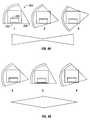
- FIGS. 4A and 4Bare schematic diagrams of a side view of a projection radiographic system illustrating examples of a detection range based on the projected images of an object in accordance with one aspect of the present invention.
- positions 1 through 6illustrate examples of different positions of x-ray sources and sensors.
- the x-ray sources and sensorsoscillate around a parcel 402 inside a projection radiographic system 404 , the relative position of a source beam 406 to the thickness of a sheet of explosives 408 in object 402 varies.
- the range of the beam from source 406defines the regions of accurate detection.
- x-ray source 406in positions 1 and 3 , exposes thin sheet of explosives 408 .
- FIG. 4Aillustrates the optimal position of x-ray source 406 for the best resolution.
- FIG. 4Billustrates another example of a good detection region when x-ray source 406 is in positions 4 and 6 since the beam is lined up with the length of sheet of explosives 408 .
- a limited view reconstruction techniquecan be used to approximate a three-dimensional model of the parcel content.
- the systemcan approximate the three-dimensional model of the parcel content while the conveyor moves at full speed, for example 500 mm per second.
- the sheet of explosivescan be detected by its characteristic appearance and further confirmed by its signature character within the “good detection region.”
- FIG. 5is a schematic of a top view of an object 502 being scanned by a projection radiographic system in accordance with one aspect of the present invention.
- FIG. 5is a schematic of a top view of an object 502 being scanned by a projection radiographic system in accordance with one aspect of the present invention.
- the projected images of a parcel 502are supplied to a control system 514 for generating a reconstructed three-dimensional image of the content of parcel 502 .
- the two x-ray sources 504 and 506oscillate within their respective limited range around parcel 502 as parcel 502 travels in direction 516 across both x-ray sources 504 and 506 on top of a conveyor belt 508 .
- Sensors 510 and 512opposite to x-ray sources 504 and 506 , respectively, capture the projected images of the content of parcel 502 and transmit the data to control system 514 .
- a processor or several processorswithin the control system 514 connected with the sensors 510 , 512 , receive and process the data from the sensors using a limited view reconstruction technique to generate a three-dimensional image of the content of parcel 502 .
- a storage device 518such as a hard drive, within the control system stores the data received from the sensors 510 , 512 and data of specified physical characteristics of contraband, for example the density of explosives and drugs.
- the processed three-dimensional images of the content of parcel 502are examined using data from the specified physical characteristic of contrabands stored in the storage device 518 to detect the presence of contraband or explosives in parcel 502 .
- a display device 520such as a monitor or television screen, is used to display the processed three-dimensional image of the content of parcel 502 . In the event potential explosives are detected in parcel 502 , an operator is alerted visually and optionally through sounds, such as an alarm 522 . A flashing light or a noticeable visual display may be used to capture the operator's attention.
- the operatormay examine closely the display device 520 and control the display of the processed image for confirmation.
- the operatormay also choose to re-examine the content of parcel 502 by controlling the speed and direction of conveyor belt 508 via means of an input device, such as a mouse and a keyboard 524 .
- FIG. 6is a flow diagram of an overview of a process in accordance with one aspect of the present invention.
- the projection radiographic systemis initialized. Once the x-rays and sensors are positioned and initialized, the projection radiographic system starts scanning an object in block 604 . The result of the scanning process is displayed in block 606 .
- a control systemhelps determine whether the object may contain suspicious material. An alarm in block 610 is activated once the control system determines suspicious material.
- FIG. 7is a flow diagram of an initialization as specified in block 602 of FIG. 6 .
- the detector systemi.e. the screens and sensors
- the detector systemis first calibrated without the x-ray sources in block 702 .
- the detector systemis then calibrated with the x-ray sources in block 704 .
- an adjustment factor for detector systemis determined in block 706 .
- the calibration processstops in block 708 to wait for a command from an interface to initiate the scanning.
- FIG. 8is a flow diagram of a scanning process as specified in block 604 of FIG. 6 .
- the radiation sourcesi.e. the x-ray sources
- the x-ray sourcesare energized creating x-ray beams in block 802 .
- the x-ray sourcesalong with their corresponding detectors oscillate around the scanning tunnel in block 804 .
- the object to be scannedis then brought into the x-ray beam of x-ray sources in block 806 .
- Each x-ray sourceproduces a line of image that is captured by each detector in block 808 .
- the collected sampleis then adjusted for distortion by the oscillating movement of the x-ray sources in block 810 .
- a three-dimensional reconstruction sliceis created based on the matching data line from each source.
- the scanning systemscans for telltale signature of sheet of explosives. The system then expands its influence out from the optimal location of the telltale signature in block 816 . As the number of data lines reaches some predetermined value, the system begins to estimate the material type of the object by background material subtraction in block 818 .
- FIG. 9is a flow diagram of a display process as specified in block 606 of FIG. 6 .
- a two-dimentional image projectionis displayed on a screen such as a monitor.
- a cursorallows an operator to display a view of the captured slice of the object in block 904 .
- the scanning systemmay also highlight suspicious areas for an operator to further investigate in block 906 .
- the scanning systemdisplays physical information of the object in block 908 .
- a display of confidence level of detectionaccompany the display of block 908 in block 910 .
- a limited three-dimensional reconstruction techniqueis used to create a three-dimensional reconstructed image of the content of the parcel based on the data captured by the sensors. The resulting image is shown using a display device such as a monitor or television.
- a control systemexamines the three-dimensional reconstructed image for a specified physical characteristic, such as the density or shape of explosives, in the parcel. In the event that there are potential explosives in the parcel, an operator is alerted through visual and audio cues, such as alarms and flashing lights as specified in block 610 of FIG. 6 . Otherwise, the parcel leaves the projection radiation system.
Landscapes
- Physics & Mathematics (AREA)
- General Physics & Mathematics (AREA)
- Life Sciences & Earth Sciences (AREA)
- General Health & Medical Sciences (AREA)
- Analytical Chemistry (AREA)
- Biochemistry (AREA)
- Chemical & Material Sciences (AREA)
- Health & Medical Sciences (AREA)
- Immunology (AREA)
- Pathology (AREA)
- High Energy & Nuclear Physics (AREA)
- General Life Sciences & Earth Sciences (AREA)
- Geophysics (AREA)
- Analysing Materials By The Use Of Radiation (AREA)
- Image Processing (AREA)
Abstract
Description
Claims (64)
Priority Applications (3)
| Application Number | Priority Date | Filing Date | Title |
|---|---|---|---|
| US09/752,811US6473487B1 (en) | 2000-12-27 | 2000-12-27 | Method and apparatus for physical characteristics discrimination of objects using a limited view three dimensional reconstruction |
| AU2001298032AAU2001298032A1 (en) | 2000-12-27 | 2001-12-20 | Method and apparatus for discrimination of objects by physical characteristics using a limited-view three-dimensional reconstitution |
| PCT/US2001/050615WO2003027653A2 (en) | 2000-12-27 | 2001-12-20 | Method and apparatus for discrimination of objects by physical characteristics using a limited-view three-dimensional reconstitution |
Applications Claiming Priority (1)
| Application Number | Priority Date | Filing Date | Title |
|---|---|---|---|
| US09/752,811US6473487B1 (en) | 2000-12-27 | 2000-12-27 | Method and apparatus for physical characteristics discrimination of objects using a limited view three dimensional reconstruction |
Publications (1)
| Publication Number | Publication Date |
|---|---|
| US6473487B1true US6473487B1 (en) | 2002-10-29 |
Family
ID=25027949
Family Applications (1)
| Application Number | Title | Priority Date | Filing Date |
|---|---|---|---|
| US09/752,811Expired - LifetimeUS6473487B1 (en) | 2000-12-27 | 2000-12-27 | Method and apparatus for physical characteristics discrimination of objects using a limited view three dimensional reconstruction |
Country Status (3)
| Country | Link |
|---|---|
| US (1) | US6473487B1 (en) |
| AU (1) | AU2001298032A1 (en) |
| WO (1) | WO2003027653A2 (en) |
Cited By (85)
| Publication number | Priority date | Publication date | Assignee | Title |
|---|---|---|---|---|
| US20030190011A1 (en)* | 2001-10-05 | 2003-10-09 | Knut Beneke | Method and device for detecting a given material in an object using electromagnetic rays |
| US20040101097A1 (en)* | 2002-11-25 | 2004-05-27 | Kyoichiro Wakayama | Apparatus and method for detecting threats |
| US20050053185A1 (en)* | 2003-08-07 | 2005-03-10 | Predrag Sukovic | CT extremity scanner |
| US20050117701A1 (en)* | 2003-12-01 | 2005-06-02 | Nelson James M. | Backscatter imaging using hadamard transform masking |
| US20050157842A1 (en)* | 2002-07-23 | 2005-07-21 | Neeraj Agrawal | Single boom cargo scanning system |
| US20060056584A1 (en)* | 2002-07-23 | 2006-03-16 | Bryan Allman | Self-contained mobile inspection system and method |
| US7062074B1 (en)* | 1999-04-14 | 2006-06-13 | Heimann Systems Gmbh | Method of processing X-ray images |
| US20070217572A1 (en)* | 2002-07-23 | 2007-09-20 | Andreas Kotowski | Single boom cargo scanning system |
| US20070258562A1 (en)* | 2006-04-21 | 2007-11-08 | Dan-Cristian Dinca | X-ray Imaging of Baggage and Personnel Using Arrays of Discrete Sources and Multiple Collimated Beams |
| US20070269007A1 (en)* | 2006-05-05 | 2007-11-22 | Alan Akery | Multiple pass cargo inspection system |
| US20080025461A1 (en)* | 2006-02-09 | 2008-01-31 | L-3 Communications Security and Detection Systems Inc. | Tomographic imaging systems and methods |
| US20080123809A1 (en)* | 2004-09-30 | 2008-05-29 | S.C. Mb Telecom Ltd.-S.R.L. | Nonintrusive Inspection Method And System |
| US20080144768A1 (en)* | 2005-06-01 | 2008-06-19 | Endicott Interconnect Technologies, Inc. | Method of making an imaging inspection apparatus with improved cooling |
| US20080152081A1 (en)* | 2004-04-09 | 2008-06-26 | Cason W Randall | Backscatter inspection portal |
| US7453987B1 (en)* | 2004-03-04 | 2008-11-18 | Science Applications International Corporation | Method and system for high energy, low radiation power X-ray imaging of the contents of a target |
| US20090116617A1 (en)* | 2004-04-09 | 2009-05-07 | American Science And Engineering, Inc. | Multiple Image Collection and Synthesis for Personnel Screening |
| US20090116614A1 (en)* | 2002-07-23 | 2009-05-07 | Andreas Kotowski | Cargo Scanning System |
| US20090161825A1 (en)* | 2003-06-20 | 2009-06-25 | James Carver | Relocatable X-Ray Imaging System and Method for Inspecting Commercial Vehicles and Cargo Containers |
| US20100011863A1 (en)* | 2006-06-14 | 2010-01-21 | The Secretary Of State For Home Affairs | Method and apparatus for computed tomography |
| US7702069B2 (en) | 2005-02-25 | 2010-04-20 | Rapiscan Security Products, Inc. | X-ray security inspection machine |
| US20100189226A1 (en)* | 2002-07-23 | 2010-07-29 | Andreas Kotowski | Rotatable boom cargo scanning system |
| US7856081B2 (en) | 2003-09-15 | 2010-12-21 | Rapiscan Systems, Inc. | Methods and systems for rapid detection of concealed objects using fluorescence |
| US20110038453A1 (en)* | 2002-07-23 | 2011-02-17 | Edward James Morton | Compact Mobile Cargo Scanning System |
| US20110064192A1 (en)* | 2002-07-23 | 2011-03-17 | Edward James Morton | Four Sided Imaging System and Method for Detection of Contraband |
| US20110135060A1 (en)* | 2008-05-20 | 2011-06-09 | Edward James Morton | High Energy X-Ray Inspection System Using a Fan-Shaped Beam and Collimated Backscatter Detectors |
| US8098794B1 (en) | 2009-09-11 | 2012-01-17 | The United States Of America As Represented By The Administrator Of The National Aeronautics And Space Administration | Moving-article X-ray imaging system and method for 3-D image generation |
| US8135112B2 (en) | 2007-02-01 | 2012-03-13 | Rapiscan Systems, Inc. | Personnel security screening system with enhanced privacy |
| US8138770B2 (en) | 2003-09-15 | 2012-03-20 | Rapiscan Systems, Inc. | Methods and systems for the rapid detection of concealed objects |
| US8199996B2 (en) | 2007-06-21 | 2012-06-12 | Rapiscan Systems, Inc. | Systems and methods for improving directed people screening |
| US8213570B2 (en) | 2006-02-27 | 2012-07-03 | Rapiscan Systems, Inc. | X-ray security inspection machine |
| US8314394B1 (en) | 2009-11-04 | 2012-11-20 | Science Applications International Corporation | System and method for three-dimensional imaging using scattering from annihilation coincidence photons |
| US8345819B2 (en) | 2009-07-29 | 2013-01-01 | American Science And Engineering, Inc. | Top-down X-ray inspection trailer |
| US8389942B2 (en) | 2008-06-11 | 2013-03-05 | Rapiscan Systems, Inc. | Photomultiplier and detection systems |
| US8433036B2 (en) | 2008-02-28 | 2013-04-30 | Rapiscan Systems, Inc. | Scanning systems |
| US8576982B2 (en) | 2008-02-01 | 2013-11-05 | Rapiscan Systems, Inc. | Personnel screening system |
| US8576989B2 (en) | 2010-03-14 | 2013-11-05 | Rapiscan Systems, Inc. | Beam forming apparatus |
| US8579506B2 (en) | 2008-05-20 | 2013-11-12 | Rapiscan Systems, Inc. | Gantry scanner systems |
| US8644453B2 (en) | 2008-02-28 | 2014-02-04 | Rapiscan Systems, Inc. | Scanning systems |
| US8824632B2 (en) | 2009-07-29 | 2014-09-02 | American Science And Engineering, Inc. | Backscatter X-ray inspection van with top-down imaging |
| US8837669B2 (en) | 2003-04-25 | 2014-09-16 | Rapiscan Systems, Inc. | X-ray scanning system |
| US8840303B2 (en) | 2008-05-20 | 2014-09-23 | Rapiscan Systems, Inc. | Scanner systems |
| US8885794B2 (en) | 2003-04-25 | 2014-11-11 | Rapiscan Systems, Inc. | X-ray tomographic inspection system for the identification of specific target items |
| US20150030125A1 (en)* | 2013-07-23 | 2015-01-29 | Rapiscan Systems, Inc. | Methods for Improving Processing Speed For Object Inspection |
| US8963094B2 (en) | 2008-06-11 | 2015-02-24 | Rapiscan Systems, Inc. | Composite gamma-neutron detection system |
| US8971485B2 (en) | 2008-02-28 | 2015-03-03 | Rapiscan Systems, Inc. | Drive-through scanning systems |
| US8995619B2 (en) | 2010-03-14 | 2015-03-31 | Rapiscan Systems, Inc. | Personnel screening system |
| US9020095B2 (en) | 2003-04-25 | 2015-04-28 | Rapiscan Systems, Inc. | X-ray scanners |
| US9036779B2 (en) | 2008-02-28 | 2015-05-19 | Rapiscan Systems, Inc. | Dual mode X-ray vehicle scanning system |
| US9048061B2 (en) | 2005-12-16 | 2015-06-02 | Rapiscan Systems, Inc. | X-ray scanners and X-ray sources therefor |
| US9057679B2 (en) | 2012-02-03 | 2015-06-16 | Rapiscan Systems, Inc. | Combined scatter and transmission multi-view imaging system |
| US9069092B2 (en) | 2012-02-22 | 2015-06-30 | L-3 Communication Security and Detection Systems Corp. | X-ray imager with sparse detector array |
| US9113839B2 (en) | 2003-04-25 | 2015-08-25 | Rapiscon Systems, Inc. | X-ray inspection system and method |
| US9158027B2 (en) | 2008-02-28 | 2015-10-13 | Rapiscan Systems, Inc. | Mobile scanning systems |
| US9218933B2 (en) | 2011-06-09 | 2015-12-22 | Rapidscan Systems, Inc. | Low-dose radiographic imaging system |
| US9223050B2 (en) | 2005-04-15 | 2015-12-29 | Rapiscan Systems, Inc. | X-ray imaging system having improved mobility |
| US9285325B2 (en) | 2007-02-01 | 2016-03-15 | Rapiscan Systems, Inc. | Personnel screening system |
| US9310323B2 (en) | 2009-05-16 | 2016-04-12 | Rapiscan Systems, Inc. | Systems and methods for high-Z threat alarm resolution |
| US9557427B2 (en) | 2014-01-08 | 2017-01-31 | Rapiscan Systems, Inc. | Thin gap chamber neutron detectors |
| US20170031053A1 (en)* | 2015-07-22 | 2017-02-02 | UHV Technologies, Inc. | X-ray imaging and chemical analysis of plant roots |
| US9632205B2 (en) | 2011-02-08 | 2017-04-25 | Rapiscan Systems, Inc. | Covert surveillance using multi-modality sensing |
| US20170287173A1 (en)* | 2016-03-31 | 2017-10-05 | General Electric Company | Ct imaging apparatus and method, and x-ray transceiving component for ct imaging apparatus |
| US9791590B2 (en) | 2013-01-31 | 2017-10-17 | Rapiscan Systems, Inc. | Portable security inspection system |
| US9823383B2 (en) | 2013-01-07 | 2017-11-21 | Rapiscan Systems, Inc. | X-ray scanner with partial energy discriminating detector array |
| US9891314B2 (en) | 2014-03-07 | 2018-02-13 | Rapiscan Systems, Inc. | Ultra wide band detectors |
| US9958569B2 (en) | 2002-07-23 | 2018-05-01 | Rapiscan Systems, Inc. | Mobile imaging system and method for detection of contraband |
| US10134254B2 (en) | 2014-11-25 | 2018-11-20 | Rapiscan Systems, Inc. | Intelligent security management system |
| US10295483B2 (en) | 2005-12-16 | 2019-05-21 | Rapiscan Systems, Inc. | Data collection, processing and storage systems for X-ray tomographic images |
| US10345479B2 (en) | 2015-09-16 | 2019-07-09 | Rapiscan Systems, Inc. | Portable X-ray scanner |
| US10591424B2 (en) | 2003-04-25 | 2020-03-17 | Rapiscan Systems, Inc. | X-ray tomographic inspection systems for the identification of specific target items |
| US10720300B2 (en) | 2016-09-30 | 2020-07-21 | American Science And Engineering, Inc. | X-ray source for 2D scanning beam imaging |
| US11175245B1 (en) | 2020-06-15 | 2021-11-16 | American Science And Engineering, Inc. | Scatter X-ray imaging with adaptive scanning beam intensity |
| US11280898B2 (en) | 2014-03-07 | 2022-03-22 | Rapiscan Systems, Inc. | Radar-based baggage and parcel inspection systems |
| US11300703B2 (en) | 2015-03-20 | 2022-04-12 | Rapiscan Systems, Inc. | Hand-held portable backscatter inspection system |
| US11340361B1 (en) | 2020-11-23 | 2022-05-24 | American Science And Engineering, Inc. | Wireless transmission detector panel for an X-ray scanner |
| US11397269B2 (en) | 2020-01-23 | 2022-07-26 | Rapiscan Systems, Inc. | Systems and methods for compton scatter and/or pulse pileup detection |
| US11525930B2 (en) | 2018-06-20 | 2022-12-13 | American Science And Engineering, Inc. | Wavelength-shifting sheet-coupled scintillation detectors |
| US11579327B2 (en) | 2012-02-14 | 2023-02-14 | American Science And Engineering, Inc. | Handheld backscatter imaging systems with primary and secondary detector arrays |
| US11778717B2 (en) | 2020-06-30 | 2023-10-03 | VEC Imaging GmbH & Co. KG | X-ray source with multiple grids |
| US11796489B2 (en) | 2021-02-23 | 2023-10-24 | Rapiscan Systems, Inc. | Systems and methods for eliminating cross-talk signals in one or more scanning systems having multiple X-ray sources |
| US12061309B2 (en) | 2008-02-28 | 2024-08-13 | Rapiscan Systems, Inc. | Drive-through scanning systems |
| US12181422B2 (en) | 2019-09-16 | 2024-12-31 | Rapiscan Holdings, Inc. | Probabilistic image analysis |
| US12230468B2 (en) | 2022-06-30 | 2025-02-18 | Varex Imaging Corporation | X-ray system with field emitters and arc protection |
| US12259341B2 (en) | 2021-11-04 | 2025-03-25 | Rapiscan Holdings, Inc. | Targeted collimation of detectors using rear collimators |
| US12283389B2 (en) | 2021-10-01 | 2025-04-22 | Rapiscan Holdings, Inc. | Methods and systems for the concurrent generation of multiple substantially similar X-ray beams |
| US12385854B2 (en) | 2022-07-26 | 2025-08-12 | Rapiscan Holdings, Inc. | Methods and systems for performing on-the-fly automatic calibration adjustments of X-ray inspection systems |
Citations (51)
| Publication number | Priority date | Publication date | Assignee | Title |
|---|---|---|---|---|
| US3581087A (en) | 1968-10-25 | 1971-05-25 | Panametrics | X-ray fluorescence measuring system employing balanced x-ray filters and circuit means to vary the effective relative transmission thereof |
| US3884816A (en) | 1972-12-19 | 1975-05-20 | Jeol Ltd | Method and apparatus for detecting dangerous articles and/or precious metals |
| USRE28544E (en) | 1971-07-07 | 1975-09-02 | Radiant energy imaging with scanning pencil beam | |
| US3924064A (en) | 1973-03-27 | 1975-12-02 | Hitachi Medical Corp | X-ray inspection equipment for baggage |
| US4075492A (en) | 1974-11-29 | 1978-02-21 | The Board Of Trustees Of Leland Stanford Junior University | Fan beam X- or γ-ray 3-D tomography |
| US4138721A (en) | 1976-11-11 | 1979-02-06 | Board of Trustees of The Lelane Standard Junior University | Limited scan angle fan beam computerized tomography |
| US4174481A (en) | 1976-03-31 | 1979-11-13 | Siemens Aktiengesellschaft | Tomographic X-ray apparatus for the production of transverse layer images |
| US4196352A (en)* | 1978-04-28 | 1980-04-01 | General Electric Company | Multiple purpose high speed tomographic x-ray scanner |
| US4228353A (en) | 1978-05-02 | 1980-10-14 | Johnson Steven A | Multiple-phase flowmeter and materials analysis apparatus and method |
| US4267446A (en) | 1979-04-03 | 1981-05-12 | Geoco, Inc. | Dual scintillation detector for determining grade of uranium ore |
| US4298800A (en) | 1978-02-27 | 1981-11-03 | Computome Corporation | Tomographic apparatus and method for obtaining three-dimensional information by radiation scanning |
| US4303830A (en)* | 1978-12-07 | 1981-12-01 | Siemens Aktiengesellschaft | Tomographic apparatus for producing transverse layer images of a radiography subject |
| US4426721A (en) | 1980-10-07 | 1984-01-17 | Diagnostic Information, Inc. | X-ray intensifier detector system for x-ray electronic radiography |
| US4472822A (en) | 1980-05-19 | 1984-09-18 | American Science And Engineering, Inc. | X-Ray computed tomography using flying spot mechanical scanning mechanism |
| USRE32164E (en) | 1980-12-01 | 1986-05-27 | The University Of Utah | Radiographic systems employing multi-linear arrays of electronic radiation detectors |
| US4637040A (en) | 1983-07-28 | 1987-01-13 | Elscint, Ltd. | Plural source computerized tomography device with improved resolution |
| USRE32779E (en) | 1980-12-01 | 1988-11-08 | University Of Utah | Radiographic systems employing multi-linear arrays of electronic radiation detectors |
| US4783794A (en) | 1985-08-29 | 1988-11-08 | Heimann Gmbh | Baggage inspection system |
| US4809312A (en) | 1986-07-22 | 1989-02-28 | American Science And Engineering, Inc. | Method and apparatus for producing tomographic images |
| US4821306A (en) | 1984-06-19 | 1989-04-11 | B.V. Optische Industrie "De Oude Delft" | System for detecting two X-ray energies |
| US4825454A (en) | 1987-12-28 | 1989-04-25 | American Science And Engineering, Inc. | Tomographic imaging with concentric conical collimator |
| US4841554A (en) | 1987-03-11 | 1989-06-20 | Heimann Gmbh | X-ray scanner for inspecting articles moving therethrough |
| US4899283A (en) | 1987-11-23 | 1990-02-06 | American Science And Engineering, Inc. | Tomographic apparatus including means to illuminate the bounded field of view from a plurality of directions |
| US4958363A (en) | 1986-08-15 | 1990-09-18 | Nelson Robert S | Apparatus for narrow bandwidth and multiple energy x-ray imaging |
| US5073782A (en) | 1988-04-19 | 1991-12-17 | Millitech Corporation | Contraband detection system |
| WO1992002892A1 (en) | 1990-08-10 | 1992-02-20 | Vivid Technologies, Inc. | Device and method for inspection of baggage and other objects |
| US5179581A (en) | 1989-09-13 | 1993-01-12 | American Science And Engineering, Inc. | Automatic threat detection based on illumination by penetrating radiant energy |
| US5181234A (en) | 1990-08-06 | 1993-01-19 | Irt Corporation | X-ray backscatter detection system |
| US5227800A (en) | 1988-04-19 | 1993-07-13 | Millitech Corporation | Contraband detection system |
| US5247561A (en) | 1991-01-02 | 1993-09-21 | Kotowski Andreas F | Luggage inspection device |
| US5349191A (en) | 1993-11-03 | 1994-09-20 | Triumf | Gamma ray detector for three-dimensional position encoding |
| US5432234A (en) | 1989-12-20 | 1995-07-11 | Nippon Oil Co., Ltd. | Resin, process for preparing the same and compositon comprising the same |
| US5442672A (en) | 1993-03-31 | 1995-08-15 | Bjorkholm; Paul J. | Three-dimensional reconstruction based on a limited number of X-ray projections |
| US5479023A (en) | 1992-04-09 | 1995-12-26 | Institute Of Geological And Nuclear Sciences, Ltd. | Method and apparatus for detecting concealed substances |
| US5481584A (en) | 1994-11-23 | 1996-01-02 | Tang; Jihong | Device for material separation using nondestructive inspection imaging |
| US5490196A (en) | 1994-03-18 | 1996-02-06 | Metorex International Oy | Multi energy system for x-ray imaging applications |
| US5600700A (en) | 1995-09-25 | 1997-02-04 | Vivid Technologies, Inc. | Detecting explosives or other contraband by employing transmitted and scattered X-rays |
| US5642393A (en) | 1995-09-26 | 1997-06-24 | Vivid Technologies, Inc. | Detecting contraband by employing interactive multiprobe tomography |
| US5699400A (en) | 1996-05-08 | 1997-12-16 | Vivid Technologies, Inc. | Operator console for article inspection systems |
| US5712926A (en) | 1994-10-20 | 1998-01-27 | Eberhard; Jeffrey Wayne | X-ray computed tomography (CT) system for detecting thin objects |
| US5812630A (en) | 1993-09-15 | 1998-09-22 | U.S. Philips Corporation | Examination method for the evaluation of location-dependent spectra |
| US5901198A (en) | 1997-10-10 | 1999-05-04 | Analogic Corporation | Computed tomography scanning target detection using target surface normals |
| US5917880A (en) | 1997-05-29 | 1999-06-29 | Eg&G Astrophysics | X-ray inspection apparatus |
| US5940468A (en) | 1996-11-08 | 1999-08-17 | American Science And Engineering, Inc. | Coded aperture X-ray imaging system |
| US5966422A (en)* | 1992-07-20 | 1999-10-12 | Picker Medical Systems, Ltd. | Multiple source CT scanner |
| US5974111A (en) | 1996-09-24 | 1999-10-26 | Vivid Technologies, Inc. | Identifying explosives or other contraband by employing transmitted or scattered X-rays |
| US6018562A (en)* | 1995-11-13 | 2000-01-25 | The United States Of America As Represented By The Secretary Of The Army | Apparatus and method for automatic recognition of concealed objects using multiple energy computed tomography |
| US6078642A (en) | 1998-02-11 | 2000-06-20 | Analogice Corporation | Apparatus and method for density discrimination of objects in computed tomography data using multiple density ranges |
| US6081580A (en) | 1997-09-09 | 2000-06-27 | American Science And Engineering, Inc. | Tomographic inspection system |
| US6088423A (en) | 1998-06-05 | 2000-07-11 | Vivid Technologies, Inc. | Multiview x-ray based system for detecting contraband such as in baggage |
| US6094472A (en) | 1998-04-14 | 2000-07-25 | Rapiscan Security Products, Inc. | X-ray backscatter imaging system including moving body tracking assembly |
Family Cites Families (5)
| Publication number | Priority date | Publication date | Assignee | Title |
|---|---|---|---|---|
| DE2614083B2 (en)* | 1976-04-01 | 1979-02-08 | Siemens Ag, 1000 Berlin Und 8000 Muenchen | X-ray film device for the production of transverse slice images |
| DE2658533C2 (en)* | 1976-12-23 | 1987-02-26 | Siemens AG, 1000 Berlin und 8000 München | Device for displaying longitudinal body layers |
| DE4023414A1 (en)* | 1989-08-09 | 1991-02-14 | Heimann Gmbh | Security arrangement passing fan-shaped beam through objects - has two sources passing beams through object from different directions to associated L=shaped receivers |
| US5367552A (en)* | 1991-10-03 | 1994-11-22 | In Vision Technologies, Inc. | Automatic concealed object detection system having a pre-scan stage |
| DE4210516C2 (en)* | 1992-03-30 | 1994-10-20 | Jens Rainer Schuessler | Process for checking luggage and use of luggage in the process |
- 2000
- 2000-12-27USUS09/752,811patent/US6473487B1/ennot_activeExpired - Lifetime
- 2001
- 2001-12-20WOPCT/US2001/050615patent/WO2003027653A2/ennot_activeApplication Discontinuation
- 2001-12-20AUAU2001298032Apatent/AU2001298032A1/ennot_activeAbandoned
Patent Citations (55)
| Publication number | Priority date | Publication date | Assignee | Title |
|---|---|---|---|---|
| US3581087A (en) | 1968-10-25 | 1971-05-25 | Panametrics | X-ray fluorescence measuring system employing balanced x-ray filters and circuit means to vary the effective relative transmission thereof |
| USRE28544E (en) | 1971-07-07 | 1975-09-02 | Radiant energy imaging with scanning pencil beam | |
| US3884816A (en) | 1972-12-19 | 1975-05-20 | Jeol Ltd | Method and apparatus for detecting dangerous articles and/or precious metals |
| US3924064A (en) | 1973-03-27 | 1975-12-02 | Hitachi Medical Corp | X-ray inspection equipment for baggage |
| US4075492A (en) | 1974-11-29 | 1978-02-21 | The Board Of Trustees Of Leland Stanford Junior University | Fan beam X- or γ-ray 3-D tomography |
| US4174481A (en) | 1976-03-31 | 1979-11-13 | Siemens Aktiengesellschaft | Tomographic X-ray apparatus for the production of transverse layer images |
| US4138721A (en) | 1976-11-11 | 1979-02-06 | Board of Trustees of The Lelane Standard Junior University | Limited scan angle fan beam computerized tomography |
| US4298800A (en) | 1978-02-27 | 1981-11-03 | Computome Corporation | Tomographic apparatus and method for obtaining three-dimensional information by radiation scanning |
| US4196352A (en)* | 1978-04-28 | 1980-04-01 | General Electric Company | Multiple purpose high speed tomographic x-ray scanner |
| US4228353A (en) | 1978-05-02 | 1980-10-14 | Johnson Steven A | Multiple-phase flowmeter and materials analysis apparatus and method |
| US4303830A (en)* | 1978-12-07 | 1981-12-01 | Siemens Aktiengesellschaft | Tomographic apparatus for producing transverse layer images of a radiography subject |
| US4267446A (en) | 1979-04-03 | 1981-05-12 | Geoco, Inc. | Dual scintillation detector for determining grade of uranium ore |
| US4472822A (en) | 1980-05-19 | 1984-09-18 | American Science And Engineering, Inc. | X-Ray computed tomography using flying spot mechanical scanning mechanism |
| US4426721A (en) | 1980-10-07 | 1984-01-17 | Diagnostic Information, Inc. | X-ray intensifier detector system for x-ray electronic radiography |
| USRE32164E (en) | 1980-12-01 | 1986-05-27 | The University Of Utah | Radiographic systems employing multi-linear arrays of electronic radiation detectors |
| USRE32779E (en) | 1980-12-01 | 1988-11-08 | University Of Utah | Radiographic systems employing multi-linear arrays of electronic radiation detectors |
| US4637040A (en) | 1983-07-28 | 1987-01-13 | Elscint, Ltd. | Plural source computerized tomography device with improved resolution |
| US4821306A (en) | 1984-06-19 | 1989-04-11 | B.V. Optische Industrie "De Oude Delft" | System for detecting two X-ray energies |
| US4783794A (en) | 1985-08-29 | 1988-11-08 | Heimann Gmbh | Baggage inspection system |
| US4809312A (en) | 1986-07-22 | 1989-02-28 | American Science And Engineering, Inc. | Method and apparatus for producing tomographic images |
| US4958363A (en) | 1986-08-15 | 1990-09-18 | Nelson Robert S | Apparatus for narrow bandwidth and multiple energy x-ray imaging |
| US4841554A (en) | 1987-03-11 | 1989-06-20 | Heimann Gmbh | X-ray scanner for inspecting articles moving therethrough |
| US4899283A (en) | 1987-11-23 | 1990-02-06 | American Science And Engineering, Inc. | Tomographic apparatus including means to illuminate the bounded field of view from a plurality of directions |
| US4825454A (en) | 1987-12-28 | 1989-04-25 | American Science And Engineering, Inc. | Tomographic imaging with concentric conical collimator |
| US5073782A (en) | 1988-04-19 | 1991-12-17 | Millitech Corporation | Contraband detection system |
| US5227800A (en) | 1988-04-19 | 1993-07-13 | Millitech Corporation | Contraband detection system |
| US5179581A (en) | 1989-09-13 | 1993-01-12 | American Science And Engineering, Inc. | Automatic threat detection based on illumination by penetrating radiant energy |
| US5432234A (en) | 1989-12-20 | 1995-07-11 | Nippon Oil Co., Ltd. | Resin, process for preparing the same and compositon comprising the same |
| US5181234A (en) | 1990-08-06 | 1993-01-19 | Irt Corporation | X-ray backscatter detection system |
| US5181234B1 (en) | 1990-08-06 | 2000-01-04 | Rapiscan Security Products Inc | X-ray backscatter detection system |
| US5490218A (en) | 1990-08-10 | 1996-02-06 | Vivid Technologies, Inc. | Device and method for inspection of baggage and other objects |
| WO1992002892A1 (en) | 1990-08-10 | 1992-02-20 | Vivid Technologies, Inc. | Device and method for inspection of baggage and other objects |
| US5838758A (en) | 1990-08-10 | 1998-11-17 | Vivid Technologies | Device and method for inspection of baggage and other objects |
| US5247561A (en) | 1991-01-02 | 1993-09-21 | Kotowski Andreas F | Luggage inspection device |
| US5479023A (en) | 1992-04-09 | 1995-12-26 | Institute Of Geological And Nuclear Sciences, Ltd. | Method and apparatus for detecting concealed substances |
| US5966422A (en)* | 1992-07-20 | 1999-10-12 | Picker Medical Systems, Ltd. | Multiple source CT scanner |
| US5442672A (en) | 1993-03-31 | 1995-08-15 | Bjorkholm; Paul J. | Three-dimensional reconstruction based on a limited number of X-ray projections |
| US5812630A (en) | 1993-09-15 | 1998-09-22 | U.S. Philips Corporation | Examination method for the evaluation of location-dependent spectra |
| US5349191A (en) | 1993-11-03 | 1994-09-20 | Triumf | Gamma ray detector for three-dimensional position encoding |
| US5490196A (en) | 1994-03-18 | 1996-02-06 | Metorex International Oy | Multi energy system for x-ray imaging applications |
| US5712926A (en) | 1994-10-20 | 1998-01-27 | Eberhard; Jeffrey Wayne | X-ray computed tomography (CT) system for detecting thin objects |
| US5481584A (en) | 1994-11-23 | 1996-01-02 | Tang; Jihong | Device for material separation using nondestructive inspection imaging |
| US5600700A (en) | 1995-09-25 | 1997-02-04 | Vivid Technologies, Inc. | Detecting explosives or other contraband by employing transmitted and scattered X-rays |
| US5642393A (en) | 1995-09-26 | 1997-06-24 | Vivid Technologies, Inc. | Detecting contraband by employing interactive multiprobe tomography |
| US6018562A (en)* | 1995-11-13 | 2000-01-25 | The United States Of America As Represented By The Secretary Of The Army | Apparatus and method for automatic recognition of concealed objects using multiple energy computed tomography |
| US5699400A (en) | 1996-05-08 | 1997-12-16 | Vivid Technologies, Inc. | Operator console for article inspection systems |
| US5870449A (en) | 1996-05-08 | 1999-02-09 | Vivid Technologies, Inc. | Operator console for article inspection systems |
| US5974111A (en) | 1996-09-24 | 1999-10-26 | Vivid Technologies, Inc. | Identifying explosives or other contraband by employing transmitted or scattered X-rays |
| US5940468A (en) | 1996-11-08 | 1999-08-17 | American Science And Engineering, Inc. | Coded aperture X-ray imaging system |
| US5917880A (en) | 1997-05-29 | 1999-06-29 | Eg&G Astrophysics | X-ray inspection apparatus |
| US6081580A (en) | 1997-09-09 | 2000-06-27 | American Science And Engineering, Inc. | Tomographic inspection system |
| US5901198A (en) | 1997-10-10 | 1999-05-04 | Analogic Corporation | Computed tomography scanning target detection using target surface normals |
| US6078642A (en) | 1998-02-11 | 2000-06-20 | Analogice Corporation | Apparatus and method for density discrimination of objects in computed tomography data using multiple density ranges |
| US6094472A (en) | 1998-04-14 | 2000-07-25 | Rapiscan Security Products, Inc. | X-ray backscatter imaging system including moving body tracking assembly |
| US6088423A (en) | 1998-06-05 | 2000-07-11 | Vivid Technologies, Inc. | Multiview x-ray based system for detecting contraband such as in baggage |
Non-Patent Citations (8)
| Title |
|---|
| "Passenger Screening Technologies", Airline Passenger Security Screening, pp. 13-21. |
| Alvarez, et al., "Energy-Selective Reconstructions in X-ray Computerized Tomography", 1976, Phys. Med. Biol., vol. 21, No. 5, pp. 733-744. |
| Bossi et al., "Backscatter X-Ray Imaging", Oct. 1988, Materials Evaluation, vol. 46. |
| Ellenbogen, Mike, "Checking in with New Bomb Detection Strategies", printed from http://www.securityman...om/library/000190.html on Dec. 1, 1996, 6 pages. |
| Gregory, William, Medical X-Ray Measuring Device Finds Use in Explosive Detection:, Apr. 28, 1986, Aviation Week & Space Technology, vol. 124, No. 17. |
| PerkinElmer Instruments, "Z-Scan7", printed from http://instruments.perkinelmer.com/products/catalog/products/prod81.asp on Aug. 4, 2000 (3 pages). |
| Rutt, Brian, "Split-Filter Computed Tomography: A Simple Technique for Dual Energy Scanning", pages J. 1980, Comput. Assist. Tomogr., vol. 4, No. 4, pp. 501-509. |
| Technical Digest Image Processing for 2-D and 3-D Reconstruction from Projections: Theory andPractice in Medicine and the Physical Sciences. |
Cited By (206)
| Publication number | Priority date | Publication date | Assignee | Title |
|---|---|---|---|---|
| US7062074B1 (en)* | 1999-04-14 | 2006-06-13 | Heimann Systems Gmbh | Method of processing X-ray images |
| US7020241B2 (en)* | 2001-10-05 | 2006-03-28 | Heimann Systems Gmbh | Method and device for detecting a given material in an object using electromagnetic rays |
| US20030190011A1 (en)* | 2001-10-05 | 2003-10-09 | Knut Beneke | Method and device for detecting a given material in an object using electromagnetic rays |
| US8503605B2 (en) | 2002-07-23 | 2013-08-06 | Rapiscan Systems, Inc. | Four sided imaging system and method for detection of contraband |
| US7995705B2 (en) | 2002-07-23 | 2011-08-09 | Rapiscan Security Products, Inc. | Self-contained mobile inspection system and method |
| US11143783B2 (en) | 2002-07-23 | 2021-10-12 | Rapiscan Systems, Inc. | Four-sided imaging system and method for detection of contraband |
| US20060056584A1 (en)* | 2002-07-23 | 2006-03-16 | Bryan Allman | Self-contained mobile inspection system and method |
| US8385501B2 (en) | 2002-07-23 | 2013-02-26 | Rapiscan Systems, Inc. | Self contained mobile inspection system and method |
| US8356937B2 (en) | 2002-07-23 | 2013-01-22 | Rapiscan Systems, Inc. | Rotatable boom cargo scanning system |
| US7783004B2 (en) | 2002-07-23 | 2010-08-24 | Rapiscan Systems, Inc. | Cargo scanning system |
| US20070217572A1 (en)* | 2002-07-23 | 2007-09-20 | Andreas Kotowski | Single boom cargo scanning system |
| US10976465B2 (en) | 2002-07-23 | 2021-04-13 | Rapiscan Systems, Inc. | Two-sided, multi-energy imaging system and method for the inspection of cargo |
| US8059781B2 (en) | 2002-07-23 | 2011-11-15 | Rapiscan Systems, Inc. | Cargo scanning system |
| US7322745B2 (en) | 2002-07-23 | 2008-01-29 | Rapiscan Security Products, Inc. | Single boom cargo scanning system |
| US10670769B2 (en) | 2002-07-23 | 2020-06-02 | Rapiscan Systems, Inc. | Compact mobile cargo scanning system |
| US20080075232A1 (en)* | 2002-07-23 | 2008-03-27 | Neeraj Agrawal | Cargo Scanning System |
| US7486768B2 (en) | 2002-07-23 | 2009-02-03 | Rapiscan Security Products, Inc. | Self-contained mobile inspection system and method |
| US8275091B2 (en) | 2002-07-23 | 2012-09-25 | Rapiscan Systems, Inc. | Compact mobile cargo scanning system |
| US20110116597A1 (en)* | 2002-07-23 | 2011-05-19 | Neeraj Agrawal | Cargo Scanning System |
| US8491189B2 (en) | 2002-07-23 | 2013-07-23 | Rapiscan Systems, Inc. | Radiation source apparatus |
| US10007019B2 (en) | 2002-07-23 | 2018-06-26 | Rapiscan Systems, Inc. | Compact mobile cargo scanning system |
| US20080165926A1 (en)* | 2002-07-23 | 2008-07-10 | Andreas Kotowski | Single Boom Cargo Scanning System |
| US9958569B2 (en) | 2002-07-23 | 2018-05-01 | Rapiscan Systems, Inc. | Mobile imaging system and method for detection of contraband |
| US7963695B2 (en) | 2002-07-23 | 2011-06-21 | Rapiscan Systems, Inc. | Rotatable boom cargo scanning system |
| US8929509B2 (en) | 2002-07-23 | 2015-01-06 | Rapiscan Systems, Inc. | Four-sided imaging system and method for detection of contraband |
| US20050157842A1 (en)* | 2002-07-23 | 2005-07-21 | Neeraj Agrawal | Single boom cargo scanning system |
| US8668386B2 (en) | 2002-07-23 | 2014-03-11 | Rapiscan Systems, Inc. | Compact mobile cargo scanning system |
| US7369643B2 (en) | 2002-07-23 | 2008-05-06 | Rapiscan Security Products, Inc. | Single boom cargo scanning system |
| US20110064192A1 (en)* | 2002-07-23 | 2011-03-17 | Edward James Morton | Four Sided Imaging System and Method for Detection of Contraband |
| US20110038453A1 (en)* | 2002-07-23 | 2011-02-17 | Edward James Morton | Compact Mobile Cargo Scanning System |
| US7517149B2 (en) | 2002-07-23 | 2009-04-14 | Rapiscan Security Products, Inc. | Cargo scanning system |
| US7519148B2 (en) | 2002-07-23 | 2009-04-14 | Rapiscan Security Products, Inc. | Single boom cargo scanning system |
| US9223049B2 (en) | 2002-07-23 | 2015-12-29 | Rapiscan Systems, Inc. | Cargo scanning system with boom structure |
| US20110033027A1 (en)* | 2002-07-23 | 2011-02-10 | Bryan Allman | Self-Contained Mobile Inspection System and Method |
| US20090116614A1 (en)* | 2002-07-23 | 2009-05-07 | Andreas Kotowski | Cargo Scanning System |
| US8687765B2 (en) | 2002-07-23 | 2014-04-01 | Rapiscan Systems, Inc. | Cargo scanning system with boom structure |
| US20090202037A1 (en)* | 2002-07-23 | 2009-08-13 | Bryan Allman | Self-Contained Mobile Inspection System and Method |
| US9052403B2 (en) | 2002-07-23 | 2015-06-09 | Rapiscan Systems, Inc. | Compact mobile cargo scanning system |
| US20090245462A1 (en)* | 2002-07-23 | 2009-10-01 | Neeraj Agrawal | Cargo Scanning System |
| US7876880B2 (en) | 2002-07-23 | 2011-01-25 | Rapiscan Systems, Inc. | Single boom cargo scanning system |
| US20090274270A1 (en)* | 2002-07-23 | 2009-11-05 | Andreas Kotowski | Single Boom Cargo Scanning System |
| US9025731B2 (en) | 2002-07-23 | 2015-05-05 | Rapiscan Systems, Inc. | Cargo scanning system |
| US9020096B2 (en) | 2002-07-23 | 2015-04-28 | Rapiscan Systems, Inc. | Self contained mobile inspection system and method |
| US7817776B2 (en) | 2002-07-23 | 2010-10-19 | Rapiscan Systems, Inc. | Cargo scanning system |
| US7720195B2 (en) | 2002-07-23 | 2010-05-18 | Rapiscan Security Products, Inc. | Self-contained mobile inspection system and method |
| US20100189226A1 (en)* | 2002-07-23 | 2010-07-29 | Andreas Kotowski | Rotatable boom cargo scanning system |
| US20040101097A1 (en)* | 2002-11-25 | 2004-05-27 | Kyoichiro Wakayama | Apparatus and method for detecting threats |
| US7260173B2 (en)* | 2002-11-25 | 2007-08-21 | Hitachi, Ltd. | Apparatus and method for detecting threats |
| US10591424B2 (en) | 2003-04-25 | 2020-03-17 | Rapiscan Systems, Inc. | X-ray tomographic inspection systems for the identification of specific target items |
| US9113839B2 (en) | 2003-04-25 | 2015-08-25 | Rapiscon Systems, Inc. | X-ray inspection system and method |
| US10175381B2 (en) | 2003-04-25 | 2019-01-08 | Rapiscan Systems, Inc. | X-ray scanners having source points with less than a predefined variation in brightness |
| US9020095B2 (en) | 2003-04-25 | 2015-04-28 | Rapiscan Systems, Inc. | X-ray scanners |
| US8837669B2 (en) | 2003-04-25 | 2014-09-16 | Rapiscan Systems, Inc. | X-ray scanning system |
| US11796711B2 (en) | 2003-04-25 | 2023-10-24 | Rapiscan Systems, Inc. | Modular CT scanning system |
| US8885794B2 (en) | 2003-04-25 | 2014-11-11 | Rapiscan Systems, Inc. | X-ray tomographic inspection system for the identification of specific target items |
| US10901112B2 (en) | 2003-04-25 | 2021-01-26 | Rapiscan Systems, Inc. | X-ray scanning system with stationary x-ray sources |
| US9675306B2 (en) | 2003-04-25 | 2017-06-13 | Rapiscan Systems, Inc. | X-ray scanning system |
| US9442082B2 (en) | 2003-04-25 | 2016-09-13 | Rapiscan Systems, Inc. | X-ray inspection system and method |
| US9618648B2 (en) | 2003-04-25 | 2017-04-11 | Rapiscan Systems, Inc. | X-ray scanners |
| US9285498B2 (en) | 2003-06-20 | 2016-03-15 | Rapiscan Systems, Inc. | Relocatable X-ray imaging system and method for inspecting commercial vehicles and cargo containers |
| US7991113B2 (en) | 2003-06-20 | 2011-08-02 | Rapiscan Security Products, Inc. | Relocatable x-ray imaging system and method for inspecting commercial vehicles and cargo containers |
| US20090161825A1 (en)* | 2003-06-20 | 2009-06-25 | James Carver | Relocatable X-Ray Imaging System and Method for Inspecting Commercial Vehicles and Cargo Containers |
| US7769133B2 (en) | 2003-06-20 | 2010-08-03 | Rapiscan Systems, Inc. | Relocatable X-ray imaging system and method for inspecting commercial vehicles and cargo containers |
| US20080205584A1 (en)* | 2003-08-07 | 2008-08-28 | Predrag Sukovic | Ct extremity scanner |
| US7388941B2 (en)* | 2003-08-07 | 2008-06-17 | Xoran Technologies, Inc. | CT extremity scanner |
| US20050053185A1 (en)* | 2003-08-07 | 2005-03-10 | Predrag Sukovic | CT extremity scanner |
| US9915752B2 (en) | 2003-08-08 | 2018-03-13 | Rapiscan Systems, Inc. | Inspection systems with two X-ray scanners in a first stage inspection system |
| US9042511B2 (en) | 2003-08-08 | 2015-05-26 | Rapiscan Systems, Inc. | Methods and systems for the rapid detection of concealed objects |
| US7856081B2 (en) | 2003-09-15 | 2010-12-21 | Rapiscan Systems, Inc. | Methods and systems for rapid detection of concealed objects using fluorescence |
| US8428217B2 (en) | 2003-09-15 | 2013-04-23 | Rapiscan Systems, Inc. | Methods and systems for rapid detection of concealed objects |
| US9268058B2 (en) | 2003-09-15 | 2016-02-23 | Rapiscan Systems, Inc. | Methods and systems for the rapid detection of concealed objects |
| US8138770B2 (en) | 2003-09-15 | 2012-03-20 | Rapiscan Systems, Inc. | Methods and systems for the rapid detection of concealed objects |
| US8674706B2 (en) | 2003-09-15 | 2014-03-18 | Rapiscan Systems, Inc. | Methods and systems for the rapid detection of concealed objects |
| US20050117701A1 (en)* | 2003-12-01 | 2005-06-02 | Nelson James M. | Backscatter imaging using hadamard transform masking |
| US6950495B2 (en) | 2003-12-01 | 2005-09-27 | The Boeing Company | Backscatter imaging using Hadamard transform masking |
| US7453987B1 (en)* | 2004-03-04 | 2008-11-18 | Science Applications International Corporation | Method and system for high energy, low radiation power X-ray imaging of the contents of a target |
| US7796734B2 (en) | 2004-04-09 | 2010-09-14 | American Science And Engineering, Inc. | Multiple image collection and synthesis for personnel screening |
| US8605859B2 (en) | 2004-04-09 | 2013-12-10 | American Science And Engineering, Inc. | Multiple image collection and synthesis for personnel screening |
| US7809109B2 (en) | 2004-04-09 | 2010-10-05 | American Science And Engineering, Inc. | Multiple image collection and synthesis for personnel screening |
| US20080310591A1 (en)* | 2004-04-09 | 2008-12-18 | American Science And Engineering, Inc. | Backscatter Inspection Portal |
| US20100104069A1 (en)* | 2004-04-09 | 2010-04-29 | American Science And Engineering, Inc. | Multiple Image Collection and Synthesis for Personnel Screening |
| US20090116617A1 (en)* | 2004-04-09 | 2009-05-07 | American Science And Engineering, Inc. | Multiple Image Collection and Synthesis for Personnel Screening |
| US20110017917A1 (en)* | 2004-04-09 | 2011-01-27 | American Science And Engineering, Inc. | Multiple Image Collection and Synthesis for Personnel Screening |
| US20110164726A1 (en)* | 2004-04-09 | 2011-07-07 | American Science And Engineering, Inc. | Multiple Image Collection and Synthesis for Personnel Screening |
| US9020100B2 (en) | 2004-04-09 | 2015-04-28 | America Science and Engineering, Inc. | Multiple image collection and synthesis for personnel screening |
| US7593506B2 (en) | 2004-04-09 | 2009-09-22 | American Science And Engineering, Inc. | Backscatter inspection portal |
| US7400701B1 (en)* | 2004-04-09 | 2008-07-15 | American Science And Engineering, Inc. | Backscatter inspection portal |
| US20080152081A1 (en)* | 2004-04-09 | 2008-06-26 | Cason W Randall | Backscatter inspection portal |
| US20080123809A1 (en)* | 2004-09-30 | 2008-05-29 | S.C. Mb Telecom Ltd.-S.R.L. | Nonintrusive Inspection Method And System |
| US7460639B2 (en) | 2004-09-30 | 2008-12-02 | S.C. Mb Telecom Ltd.-S.R.L. | Nonintrusive inspection method and system |
| US7702069B2 (en) | 2005-02-25 | 2010-04-20 | Rapiscan Security Products, Inc. | X-ray security inspection machine |
| US9223050B2 (en) | 2005-04-15 | 2015-12-29 | Rapiscan Systems, Inc. | X-ray imaging system having improved mobility |
| US20080144768A1 (en)* | 2005-06-01 | 2008-06-19 | Endicott Interconnect Technologies, Inc. | Method of making an imaging inspection apparatus with improved cooling |
| US7490984B2 (en)* | 2005-06-01 | 2009-02-17 | Endicott Interconnect Technologies, Inc. | Method of making an imaging inspection apparatus with improved cooling |
| US10295483B2 (en) | 2005-12-16 | 2019-05-21 | Rapiscan Systems, Inc. | Data collection, processing and storage systems for X-ray tomographic images |
| US9638646B2 (en) | 2005-12-16 | 2017-05-02 | Rapiscan Systems, Inc. | X-ray scanners and X-ray sources therefor |
| US9048061B2 (en) | 2005-12-16 | 2015-06-02 | Rapiscan Systems, Inc. | X-ray scanners and X-ray sources therefor |
| US10976271B2 (en) | 2005-12-16 | 2021-04-13 | Rapiscan Systems, Inc. | Stationary tomographic X-ray imaging systems for automatically sorting objects based on generated tomographic images |
| US20080025461A1 (en)* | 2006-02-09 | 2008-01-31 | L-3 Communications Security and Detection Systems Inc. | Tomographic imaging systems and methods |
| US7606348B2 (en)* | 2006-02-09 | 2009-10-20 | L-3 Communications Security and Detection Systems Inc. | Tomographic imaging systems and methods |
| US8213570B2 (en) | 2006-02-27 | 2012-07-03 | Rapiscan Systems, Inc. | X-ray security inspection machine |
| US9310322B2 (en) | 2006-02-27 | 2016-04-12 | Rapiscan Systems, Inc. | X-ray security inspection machine |
| US20070258562A1 (en)* | 2006-04-21 | 2007-11-08 | Dan-Cristian Dinca | X-ray Imaging of Baggage and Personnel Using Arrays of Discrete Sources and Multiple Collimated Beams |
| US7505562B2 (en) | 2006-04-21 | 2009-03-17 | American Science And Engineering, Inc. | X-ray imaging of baggage and personnel using arrays of discrete sources and multiple collimated beams |
| US20110127426A1 (en)* | 2006-05-05 | 2011-06-02 | Alan Akery | Multiple Pass Cargo Inspection System |
| US8457275B2 (en) | 2006-05-05 | 2013-06-04 | Rapiscan Systems, Inc. | Multiple pass cargo inspection system |
| US8170177B2 (en) | 2006-05-05 | 2012-05-01 | Rapiscan Systems, Inc. | Multiple pass cargo inspection system |
| US7526064B2 (en) | 2006-05-05 | 2009-04-28 | Rapiscan Security Products, Inc. | Multiple pass cargo inspection system |
| US9279901B2 (en) | 2006-05-05 | 2016-03-08 | Rapiscan Systems, Inc. | Cargo inspection system |
| US7860213B2 (en) | 2006-05-05 | 2010-12-28 | Rapiscan Systems, Inc. | Multiple pass cargo inspection system |
| US20070269007A1 (en)* | 2006-05-05 | 2007-11-22 | Alan Akery | Multiple pass cargo inspection system |
| US8837670B2 (en) | 2006-05-05 | 2014-09-16 | Rapiscan Systems, Inc. | Cargo inspection system |
| US20100011863A1 (en)* | 2006-06-14 | 2010-01-21 | The Secretary Of State For Home Affairs | Method and apparatus for computed tomography |
| US8135112B2 (en) | 2007-02-01 | 2012-03-13 | Rapiscan Systems, Inc. | Personnel security screening system with enhanced privacy |
| US9291741B2 (en) | 2007-02-01 | 2016-03-22 | Rapiscan Systems, Inc. | Personnel screening system |
| US9285325B2 (en) | 2007-02-01 | 2016-03-15 | Rapiscan Systems, Inc. | Personnel screening system |
| US9182516B2 (en) | 2007-02-01 | 2015-11-10 | Rapiscan Systems, Inc. | Personnel screening system |
| US8774362B2 (en) | 2007-06-21 | 2014-07-08 | Rapiscan Systems, Inc. | Systems and methods for improving directed people screening |
| US8199996B2 (en) | 2007-06-21 | 2012-06-12 | Rapiscan Systems, Inc. | Systems and methods for improving directed people screening |
| US8576982B2 (en) | 2008-02-01 | 2013-11-05 | Rapiscan Systems, Inc. | Personnel screening system |
| US9429530B2 (en) | 2008-02-28 | 2016-08-30 | Rapiscan Systems, Inc. | Scanning systems |
| US9036779B2 (en) | 2008-02-28 | 2015-05-19 | Rapiscan Systems, Inc. | Dual mode X-ray vehicle scanning system |
| US9158027B2 (en) | 2008-02-28 | 2015-10-13 | Rapiscan Systems, Inc. | Mobile scanning systems |
| US10754058B2 (en) | 2008-02-28 | 2020-08-25 | Rapiscan Systems, Inc. | Drive-through scanning systems |
| US8433036B2 (en) | 2008-02-28 | 2013-04-30 | Rapiscan Systems, Inc. | Scanning systems |
| US9121958B2 (en) | 2008-02-28 | 2015-09-01 | Rapiscan Systems, Inc. | Scanning systems |
| US11579328B2 (en) | 2008-02-28 | 2023-02-14 | Rapiscan Systems, Inc. | Drive-through scanning systems |
| US10816691B2 (en) | 2008-02-28 | 2020-10-27 | Rapiscan Systems, Inc. | Multi-element detector systems |
| US9817151B2 (en) | 2008-02-28 | 2017-11-14 | Rapiscan Systems, Inc. | Drive-through scanning systems |
| US10007021B2 (en) | 2008-02-28 | 2018-06-26 | Rapiscan Systems, Inc. | Scanning systems |
| US8971485B2 (en) | 2008-02-28 | 2015-03-03 | Rapiscan Systems, Inc. | Drive-through scanning systems |
| US8774357B2 (en) | 2008-02-28 | 2014-07-08 | Rapiscan Systems, Inc. | Scanning systems |
| US8644453B2 (en) | 2008-02-28 | 2014-02-04 | Rapiscan Systems, Inc. | Scanning systems |
| US9835756B2 (en) | 2008-02-28 | 2017-12-05 | Rapiscan Systems, Inc. | Dual mode X-ray vehicle scanning system |
| US12061309B2 (en) | 2008-02-28 | 2024-08-13 | Rapiscan Systems, Inc. | Drive-through scanning systems |
| US8579506B2 (en) | 2008-05-20 | 2013-11-12 | Rapiscan Systems, Inc. | Gantry scanner systems |
| US8840303B2 (en) | 2008-05-20 | 2014-09-23 | Rapiscan Systems, Inc. | Scanner systems |
| US8831176B2 (en) | 2008-05-20 | 2014-09-09 | Rapiscan Systems, Inc. | High energy X-ray inspection system using a fan-shaped beam and collimated backscatter detectors |
| US9332624B2 (en) | 2008-05-20 | 2016-05-03 | Rapiscan Systems, Inc. | Gantry scanner systems |
| US10098214B2 (en) | 2008-05-20 | 2018-10-09 | Rapiscan Systems, Inc. | Detector support structures for gantry scanner systems |
| US20110135060A1 (en)* | 2008-05-20 | 2011-06-09 | Edward James Morton | High Energy X-Ray Inspection System Using a Fan-Shaped Beam and Collimated Backscatter Detectors |
| US9688517B2 (en) | 2008-05-20 | 2017-06-27 | Rapiscan Systems, Inc. | Scanner systems |
| US9329285B2 (en) | 2008-06-11 | 2016-05-03 | Rapiscan Systems, Inc. | Composite gamma-neutron detection system |
| US8963094B2 (en) | 2008-06-11 | 2015-02-24 | Rapiscan Systems, Inc. | Composite gamma-neutron detection system |
| US8735833B2 (en) | 2008-06-11 | 2014-05-27 | Rapiscan Systems, Inc | Photomultiplier and detection systems |
| US8389941B2 (en) | 2008-06-11 | 2013-03-05 | Rapiscan Systems, Inc. | Composite gamma-neutron detection system |
| US8389942B2 (en) | 2008-06-11 | 2013-03-05 | Rapiscan Systems, Inc. | Photomultiplier and detection systems |
| US8993970B2 (en) | 2008-06-11 | 2015-03-31 | Rapiscan Systems, Inc. | Photomultiplier and detection systems |
| US9310323B2 (en) | 2009-05-16 | 2016-04-12 | Rapiscan Systems, Inc. | Systems and methods for high-Z threat alarm resolution |
| US9625606B2 (en) | 2009-05-16 | 2017-04-18 | Rapiscan Systems, Inc. | Systems and methods for high-Z threat alarm resolution |
| US8824632B2 (en) | 2009-07-29 | 2014-09-02 | American Science And Engineering, Inc. | Backscatter X-ray inspection van with top-down imaging |
| US8345819B2 (en) | 2009-07-29 | 2013-01-01 | American Science And Engineering, Inc. | Top-down X-ray inspection trailer |
| US8098794B1 (en) | 2009-09-11 | 2012-01-17 | The United States Of America As Represented By The Administrator Of The National Aeronautics And Space Administration | Moving-article X-ray imaging system and method for 3-D image generation |
| US8426822B1 (en) | 2009-11-04 | 2013-04-23 | Science Application International Corporation | System and method for three-dimensional imaging using scattering from annihilation coincidence photons |
| US8314394B1 (en) | 2009-11-04 | 2012-11-20 | Science Applications International Corporation | System and method for three-dimensional imaging using scattering from annihilation coincidence photons |
| US8664609B2 (en) | 2009-11-04 | 2014-03-04 | Leidos, Inc. | System and method for three-dimensional imaging using scattering from annihilation coincidence photons |
| US9058909B2 (en) | 2010-03-14 | 2015-06-16 | Rapiscan Systems, Inc. | Beam forming apparatus |
| US8576989B2 (en) | 2010-03-14 | 2013-11-05 | Rapiscan Systems, Inc. | Beam forming apparatus |
| US8995619B2 (en) | 2010-03-14 | 2015-03-31 | Rapiscan Systems, Inc. | Personnel screening system |
| US9632205B2 (en) | 2011-02-08 | 2017-04-25 | Rapiscan Systems, Inc. | Covert surveillance using multi-modality sensing |
| US10408967B2 (en) | 2011-02-08 | 2019-09-10 | Rapiscan Systems, Inc. | Covert surveillance using multi-modality sensing |
| US10942291B2 (en) | 2011-02-08 | 2021-03-09 | Rapiscan Systems, Inc. | Covert surveillance using multi-modality sensing |
| US11822041B2 (en) | 2011-02-08 | 2023-11-21 | Rapiscan Systems, Inc. | Systems and methods for improved atomic-number based material discrimination |
| US11307325B2 (en) | 2011-02-08 | 2022-04-19 | Rapiscan Systems, Inc. | Covert surveillance using multi-modality sensing |
| US9218933B2 (en) | 2011-06-09 | 2015-12-22 | Rapidscan Systems, Inc. | Low-dose radiographic imaging system |
| US12235226B2 (en) | 2012-02-03 | 2025-02-25 | Rapiscan Systems, Inc. | Combined scatter and transmission multi-view imaging system |
| US11371948B2 (en) | 2012-02-03 | 2022-06-28 | Rapiscan Systems, Inc. | Multi-view imaging system |
| US9057679B2 (en) | 2012-02-03 | 2015-06-16 | Rapiscan Systems, Inc. | Combined scatter and transmission multi-view imaging system |
| US9823201B2 (en) | 2012-02-03 | 2017-11-21 | Rapiscan Systems, Inc. | Combined scatter and transmission multi-view imaging system |
| US10746674B2 (en) | 2012-02-03 | 2020-08-18 | Rapiscan Systems, Inc. | Combined scatter and transmission multi-view imaging system |
| US11579327B2 (en) | 2012-02-14 | 2023-02-14 | American Science And Engineering, Inc. | Handheld backscatter imaging systems with primary and secondary detector arrays |
| US9069092B2 (en) | 2012-02-22 | 2015-06-30 | L-3 Communication Security and Detection Systems Corp. | X-ray imager with sparse detector array |
| US10353109B2 (en) | 2013-01-07 | 2019-07-16 | Rapiscan Systems, Inc. | X-ray scanner with partial energy discriminating detector array |
| US9823383B2 (en) | 2013-01-07 | 2017-11-21 | Rapiscan Systems, Inc. | X-ray scanner with partial energy discriminating detector array |
| US10782440B2 (en) | 2013-01-07 | 2020-09-22 | Rapiscan Systems, Inc. | X-ray scanner with partial energy discriminating detector array |
| US10317566B2 (en) | 2013-01-31 | 2019-06-11 | Rapiscan Systems, Inc. | Portable security inspection system |
| US9791590B2 (en) | 2013-01-31 | 2017-10-17 | Rapiscan Systems, Inc. | Portable security inspection system |
| US11550077B2 (en) | 2013-01-31 | 2023-01-10 | Rapiscan Systems, Inc. | Portable vehicle inspection portal with accompanying workstation |
| US20150030125A1 (en)* | 2013-07-23 | 2015-01-29 | Rapiscan Systems, Inc. | Methods for Improving Processing Speed For Object Inspection |
| US9880314B2 (en)* | 2013-07-23 | 2018-01-30 | Rapiscan Systems, Inc. | Methods for improving processing speed for object inspection |
| US9557427B2 (en) | 2014-01-08 | 2017-01-31 | Rapiscan Systems, Inc. | Thin gap chamber neutron detectors |
| US9891314B2 (en) | 2014-03-07 | 2018-02-13 | Rapiscan Systems, Inc. | Ultra wide band detectors |
| US11280898B2 (en) | 2014-03-07 | 2022-03-22 | Rapiscan Systems, Inc. | Radar-based baggage and parcel inspection systems |
| US10713914B2 (en) | 2014-11-25 | 2020-07-14 | Rapiscan Systems, Inc. | Intelligent security management system |
| US10134254B2 (en) | 2014-11-25 | 2018-11-20 | Rapiscan Systems, Inc. | Intelligent security management system |
| US11561320B2 (en) | 2015-03-20 | 2023-01-24 | Rapiscan Systems, Inc. | Hand-held portable backscatter inspection system |
| US11300703B2 (en) | 2015-03-20 | 2022-04-12 | Rapiscan Systems, Inc. | Hand-held portable backscatter inspection system |
| US12259518B2 (en) | 2015-03-20 | 2025-03-25 | Rapiscan Systems, Inc. | Hand-held portable backscatter inspection system |
| US20170031053A1 (en)* | 2015-07-22 | 2017-02-02 | UHV Technologies, Inc. | X-ray imaging and chemical analysis of plant roots |
| US10436721B2 (en)* | 2015-07-22 | 2019-10-08 | UHV Technologies, Inc. | X-ray imaging and chemical analysis of plant roots |
| US10345479B2 (en) | 2015-09-16 | 2019-07-09 | Rapiscan Systems, Inc. | Portable X-ray scanner |
| US10517545B2 (en)* | 2016-03-31 | 2019-12-31 | General Electric Company | CT imaging apparatus and method, and X-ray transceiving component for CT imaging apparatus |
| US20170287173A1 (en)* | 2016-03-31 | 2017-10-05 | General Electric Company | Ct imaging apparatus and method, and x-ray transceiving component for ct imaging apparatus |
| US10720300B2 (en) | 2016-09-30 | 2020-07-21 | American Science And Engineering, Inc. | X-ray source for 2D scanning beam imaging |
| US11525930B2 (en) | 2018-06-20 | 2022-12-13 | American Science And Engineering, Inc. | Wavelength-shifting sheet-coupled scintillation detectors |
| US12181422B2 (en) | 2019-09-16 | 2024-12-31 | Rapiscan Holdings, Inc. | Probabilistic image analysis |
| US11397269B2 (en) | 2020-01-23 | 2022-07-26 | Rapiscan Systems, Inc. | Systems and methods for compton scatter and/or pulse pileup detection |
| US11175245B1 (en) | 2020-06-15 | 2021-11-16 | American Science And Engineering, Inc. | Scatter X-ray imaging with adaptive scanning beam intensity |
| US11778717B2 (en) | 2020-06-30 | 2023-10-03 | VEC Imaging GmbH & Co. KG | X-ray source with multiple grids |
| US11726218B2 (en) | 2020-11-23 | 2023-08-15 | American Science arid Engineering, Inc. | Methods and systems for synchronizing backscatter signals and wireless transmission signals in x-ray scanning |
| US11340361B1 (en) | 2020-11-23 | 2022-05-24 | American Science And Engineering, Inc. | Wireless transmission detector panel for an X-ray scanner |
| US11796489B2 (en) | 2021-02-23 | 2023-10-24 | Rapiscan Systems, Inc. | Systems and methods for eliminating cross-talk signals in one or more scanning systems having multiple X-ray sources |
| US12283389B2 (en) | 2021-10-01 | 2025-04-22 | Rapiscan Holdings, Inc. | Methods and systems for the concurrent generation of multiple substantially similar X-ray beams |
| US12259341B2 (en) | 2021-11-04 | 2025-03-25 | Rapiscan Holdings, Inc. | Targeted collimation of detectors using rear collimators |
| US12230468B2 (en) | 2022-06-30 | 2025-02-18 | Varex Imaging Corporation | X-ray system with field emitters and arc protection |
| US12385854B2 (en) | 2022-07-26 | 2025-08-12 | Rapiscan Holdings, Inc. | Methods and systems for performing on-the-fly automatic calibration adjustments of X-ray inspection systems |
Also Published As
| Publication number | Publication date |
|---|---|
| WO2003027653A3 (en) | 2003-11-20 |
| AU2001298032A1 (en) | 2003-04-07 |
| WO2003027653A2 (en) | 2003-04-03 |
Similar Documents
| Publication | Publication Date | Title |
|---|---|---|
| US6473487B1 (en) | Method and apparatus for physical characteristics discrimination of objects using a limited view three dimensional reconstruction | |
| US7020242B2 (en) | X-ray inspection system | |
| US7260173B2 (en) | Apparatus and method for detecting threats | |
| EP0852717B1 (en) | Detecting contraband by employing interactive multiprobe tomography | |
| US6453007B2 (en) | X-ray inspection using co-planar pencil and fan beams | |
| RU2444723C2 (en) | Apparatus and method of inspecting objects | |
| US8199996B2 (en) | Systems and methods for improving directed people screening | |
| US3790799A (en) | Radiant energy imaging with rocking scanning | |
| US6282260B1 (en) | Unilateral hand-held x-ray inspection apparatus | |
| US5260982A (en) | Scattered radiation imaging apparatus | |
| US7529341B2 (en) | Automatic material discrimination by using computer tomography | |
| US5970113A (en) | Computed tomography scanning apparatus and method with temperature compensation for dark current offsets | |
| JP2001235434A (en) | Explosive detection apparatus and method using double energy information in scanning | |
| WO2015196857A1 (en) | Detector device, dual energy ct system and detection method using same | |
| US20050276468A1 (en) | Method of and system for extracting 3D bag images from continuously reconstructed 2D image slices in computed tomography | |
| WO2000037928A9 (en) | Unilateral hand-held x-ray inspection apparatus | |
| CN102422178A (en) | X-ray scanner | |
| CN101918820A (en) | Improved security system for security of persons | |
| US20100166285A1 (en) | System and method for acquiring image data | |
| WO2014029195A1 (en) | Back scattering human body security inspection system capable of monitoring radioactive substance and scanning method therefor |
Legal Events
| Date | Code | Title | Description |
|---|---|---|---|
| AS | Assignment | Owner name:RAPISCAN SECURITY PRODUCTS, INC., CALIFORNIA Free format text:ASSIGNMENT OF ASSIGNORS INTEREST;ASSIGNOR:LE, KHAI MINH;REEL/FRAME:011830/0081 Effective date:20010511 | |
| CC | Certificate of correction | ||
| AS | Assignment | Owner name:BANK OF THE WEST, A CALIFORNIA BANKING CORPORATION Free format text:SECURITY AGREEMENT;ASSIGNOR:RAPISCAN SECURITY PRODUCTS, INC.;REEL/FRAME:016182/0832 Effective date:20050624 | |
| FEPP | Fee payment procedure | Free format text:PAT HOLDER NO LONGER CLAIMS SMALL ENTITY STATUS, ENTITY STATUS SET TO UNDISCOUNTED (ORIGINAL EVENT CODE: STOL); ENTITY STATUS OF PATENT OWNER: LARGE ENTITY | |
| REFU | Refund | Free format text:REFUND - SURCHARGE, PETITION TO ACCEPT PYMT AFTER EXP, UNINTENTIONAL (ORIGINAL EVENT CODE: R2551); ENTITY STATUS OF PATENT OWNER: LARGE ENTITY | |
| FPAY | Fee payment | Year of fee payment:4 | |
| AS | Assignment | Owner name:WACHOVIA BANK, NATIONAL ASSOCIATION, AS ADMINISTRA Free format text:NOTICE OF GRANT OF SECURITY INTEREST;ASSIGNOR:RAPISCAN SECURITY PRODUCTS, INC.;REEL/FRAME:019690/0142 Effective date:20070727 | |
| FEPP | Fee payment procedure | Free format text:PAYOR NUMBER ASSIGNED (ORIGINAL EVENT CODE: ASPN); ENTITY STATUS OF PATENT OWNER: LARGE ENTITY | |
| AS | Assignment | Owner name:RAPISCAN SECURITY PRODUCTS, INC., CALIFORNIA Free format text:TERMINATION OF SECURITY INTEREST IN PATENTS;ASSIGNOR:BANK OF THE WEST;REEL/FRAME:020638/0727 Effective date:20070727 Owner name:RAPISCAN SECURITY PRODUCTS, INC., CALIFORNIA Free format text:TERMINATION OF SECURITY INTEREST IN PATENTS;ASSIGNOR:BANK OF THE WEST;REEL/FRAME:020638/0722 Effective date:20070727 | |
| AS | Assignment | Owner name:RAPISCAN SYSTEMS, INC., CALIFORNIA Free format text:CHANGE OF NAME;ASSIGNOR:RAPISCAN SECURITY PRODUCTS, INC.;REEL/FRAME:022222/0844 Effective date:20090115 Owner name:RAPISCAN SYSTEMS, INC.,CALIFORNIA Free format text:CHANGE OF NAME;ASSIGNOR:RAPISCAN SECURITY PRODUCTS, INC.;REEL/FRAME:022222/0844 Effective date:20090115 | |
| FPAY | Fee payment | Year of fee payment:8 | |
| AS | Assignment | Owner name:WELLS FARGO BANK, NATIONAL ASSOCIATION, AS ADMINIS Free format text:NOTICE OF GRANT OF SECURITY INTEREST IN PATENTS;ASSIGNOR:RAPISCAN SYSTEMS, INC.;REEL/FRAME:025150/0944 Effective date:20070727 | |
| AS | Assignment | Owner name:RAPISCAN SECURITY PRODUCTS, INC., CALIFORNIA Free format text:TERMINATION OF SECURITY INTEREST IN PATENTS;ASSIGNOR:WELLS FARGO BANK, NATIONAL ASSOCIATION, SUCCESSOR-BY-MERGER TO WACHOVIA BANK, NATIONAL ASSOCIATION, AS ADMINISTRATIVE AGENT;REEL/FRAME:025227/0169 Effective date:20101015 | |
| REMI | Maintenance fee reminder mailed | ||
| LAPS | Lapse for failure to pay maintenance fees | ||
| REIN | Reinstatement after maintenance fee payment confirmed | ||
| FEPP | Fee payment procedure | Free format text:PETITION RELATED TO MAINTENANCE FEES FILED (ORIGINAL EVENT CODE: PMFP); ENTITY STATUS OF PATENT OWNER: LARGE ENTITY Free format text:PETITION RELATED TO MAINTENANCE FEES GRANTED (ORIGINAL EVENT CODE: PMFG); ENTITY STATUS OF PATENT OWNER: LARGE ENTITY | |
| FP | Lapsed due to failure to pay maintenance fee | Effective date:20141029 | |
| PRDP | Patent reinstated due to the acceptance of a late maintenance fee | Effective date:20150821 | |
| FPAY | Fee payment | Year of fee payment:12 | |
| STCF | Information on status: patent grant | Free format text:PATENTED CASE | |
| SULP | Surcharge for late payment |