US6473167B1 - Position and orientation determination using stationary fan beam sources and rotating mirrors to sweep fan beams - Google Patents
Position and orientation determination using stationary fan beam sources and rotating mirrors to sweep fan beamsDownload PDFInfo
- Publication number
- US6473167B1 US6473167B1US09/880,146US88014601AUS6473167B1US 6473167 B1US6473167 B1US 6473167B1US 88014601 AUS88014601 AUS 88014601AUS 6473167 B1US6473167 B1US 6473167B1
- Authority
- US
- United States
- Prior art keywords
- mirrors
- shaft
- beams
- fan
- light
- Prior art date
- Legal status (The legal status is an assumption and is not a legal conclusion. Google has not performed a legal analysis and makes no representation as to the accuracy of the status listed.)
- Expired - Lifetime
Links
- 238000000034methodMethods0.000claimsabstractdescription23
- 238000005259measurementMethods0.000abstractdescription6
- 230000005019pattern of movementEffects0.000abstractdescription2
- 230000004075alterationEffects0.000description1
- 238000013459approachMethods0.000description1
- 230000003190augmentative effectEffects0.000description1
- 238000011960computer-aided designMethods0.000description1
- 238000001514detection methodMethods0.000description1
- 239000003814drugSubstances0.000description1
- 230000000694effectsEffects0.000description1
- 230000007246mechanismEffects0.000description1
- 238000012986modificationMethods0.000description1
- 230000004048modificationEffects0.000description1
- 238000012544monitoring processMethods0.000description1
- 230000003287optical effectEffects0.000description1
- 238000012360testing methodMethods0.000description1
Images


Classifications
- G—PHYSICS
- G01—MEASURING; TESTING
- G01S—RADIO DIRECTION-FINDING; RADIO NAVIGATION; DETERMINING DISTANCE OR VELOCITY BY USE OF RADIO WAVES; LOCATING OR PRESENCE-DETECTING BY USE OF THE REFLECTION OR RERADIATION OF RADIO WAVES; ANALOGOUS ARRANGEMENTS USING OTHER WAVES
- G01S5/00—Position-fixing by co-ordinating two or more direction or position line determinations; Position-fixing by co-ordinating two or more distance determinations
- G01S5/16—Position-fixing by co-ordinating two or more direction or position line determinations; Position-fixing by co-ordinating two or more distance determinations using electromagnetic waves other than radio waves
Definitions
- the present inventionrelates to position and orientation determination using stationary fan beam sources and rotating mirrors to sweep fan beams.
- the present inventionhas applications in diverse areas such as medicine, aerospace, and virtual reality. Additionally, the present invention may be employed for position and orientation monitoring of surgical instruments, for cockpit-based helmet mounted siting mechanisms, and for augmented reality computer-aided design.
- Parker and Dornbuschuse three scanner mirrors and laser sources to measure angles of inclination from three source points. Orman measures position of a detector using three fan beams rotating about one axis but Orman requires an awkward arrangement of optical fan beam sources with the sources rotating about a common axis.
- the present inventiondiffers from the teachings of the prior art listed above in that, in the present invention, the fan beam sources are stationary and are directed toward one or more rotating mirrors with the fan beams reflected from the mirrors moving through a measuring space in a controlled predictable manner.
- the present inventionrelates to position and orientation determination using moving means comprising stationary fan beam sources and rotating mirrors to sweep fan beams.
- moving meanscomprising stationary fan beam sources and rotating mirrors to sweep fan beams.
- the present inventionincludes the following interrelated objects, aspects and features:
- motor meanscomprises a single motor having drive shaft means comprising an elongated drive shaft.
- the drive shafthas preferably mounted thereon reflector means comprising two mirrors, the reflective faces of which lie in common planes.
- the reflector meanscan comprise a single elongated mirror. In any event, the reflective surfaces thereof should be in a common plane.
- each reflective face of each mirroris generally rectangular and the reflective faces or facets face in diametrically opposite directions spaced 180° apart.
- the shaftmay be provided with a single elongated mirror having one or more faces or some amount of mirrors greater than two mirrors. If desired, four reflective faces spaced 90° apart may be employed.
- Fan beamsare generated in the first embodiment through the use of stationary laser beam sources which are aimed at each mirror. As the mirrors rotate, each stationary source is reflected off a particular mirror and into a measuring space in a predictable pattern of movement.
- the control means incorporated in the first embodiment of the present inventionis provided with knowledge as to the rotative position of the mirrors at any given time.
- Sensor meanscomprising a sensor is attached to the object to be measured, which sensor is able to detect the time of arrival of impinging scanning beams. At least one of the fan-shaped beams is skewed with respect to other beams, and at least two of the fan-shaped beams have origins sufficiently separated to allow accurate triangulation of the position of the sensor over various regions of the measuring space. In this way, accurate measurement of position and orientation may be carried out.
- Computing meansdetermine reflected fan beam planes from knowledge of incident fan beam planes and mirror positions corresponding to detector times of arrival. As is familiar to those skilled in the art, the reflected beam angle with respect to the mirror normal is equal to the incident beam angle.
- Detector positionis computed as the intersection of three beam planes, as is a well known procedure to those skilled in the art. The positions of three detectors are used to define a plane, from which the sensor orientation is determined, also a familiar procedure to those skilled in the art. In this way, the sensor position and orientation (6DOF) is determined.
- motor meanscomprises separate drive motors, each of which carries reflector means comprising a mirror with the drive shafts of the motors preferably being parallel to one another and with the reflective surfaces of the mirrors lying in either common planes or parallel planes.
- reflector meanscomprising a mirror with the drive shafts of the motors preferably being parallel to one another and with the reflective surfaces of the mirrors lying in either common planes or parallel planes.
- reflective surfaces of the mirrorslie in common planes. As the mirrors rotate from those positions, at other orientations thereof, the mirrors lie in parallel planes.
- fan-shaped beamsare generated through stationary sources of laser beams that are directed at the reflective surfaces of the mirrors and thence reflect into the measuring space.
- Each mirrormay consist of a single reflective surface or a plurality of reflective surfaces such as two opposed surfaces or four surfaces where each reflective surface is related to adjacent reflective surfaces by a right angle.
- control means of the present inventionelectrical circuitry is incorporated in the second embodiment and provided with knowledge of the rotative position of each shaft and reflective surface and the sensor detects times of arrival of the various fan-shaped beams. With the shafts of the two motors spaced sufficiently apart and with at least two of the fan-shaped beams skewed with respect to one another, the control means is programmed so that triangulation may be carried out to determine the position and orientation of an object within the measuring space.
- Computing meansdetermine reflected fan beam planes from knowledge of incident fan beam planes and mirror positions corresponding to detector times of arrival. As is familiar to those skilled in the art, the reflected beam angle with respect to the mirror normal is equal to the incident beam angle.
- Detector positionis computed as the intersection of three beam planes, as is a well known procedure to those skilled in the art. The positions of three detectors are used to define a plane, from which the sensor orientation is determined, also a familiar procedure to those skilled in the art. In this way, the sensor position and orientation (6DOF) is determined.
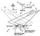
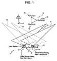
- FIG. 1shows a schematic representation of a first embodiment of the present invention.
- FIG. 2shows a front view of the fan-shaped beam generating system of the embodiment of FIG. 1 .
- FIG. 3shows a top view of the beam generating subsystem of the first embodiment of the present invention.
- FIG. 4shows a side view of the beam generating subsystem of the first embodiment of the present invention.
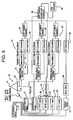
- FIG. 5shows a schematic representation of the electrical circuitry of the first embodiment of the present invention.
- FIG. 6shows a front view of a second embodiment of fan-shaped beam generating subsystem.
- FIG. 7shows a top view of a second embodiment of fan-shaped beam generating subsystem.
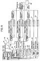
- FIG. 8shows a schematic representation of the electrical circuitry for the second embodiment of the present invention.
- the systemis generally designated by the reference numeral 10 and is seen to include a scanner housing 11 on which is mounted a motor 13 having a shaft 15 to which are affixed two mirrors 17 and 19 .
- the mirror 17includes two reflective faces 21 and 23 which face in diametrically opposite directions.
- the face 21is seen in FIG. 2 .
- the mirror 19includes faces 25 and 27 which face in diametrically opposite directions with the face 25 seen in FIG. 2 .
- the housing 11includes four laser beam sources numbered 29 , 31 , 33 and 35 , respectively.
- the laser beamsreflect from the mirrors 17 and 19 to form the fan-shaped beams illustrated in FIG. 1 .
- the beam 29reflects off one of the faces 21 , 23 of the mirror 17 to create the beam 37 .
- the laser beam 31reflects off one of the faces of the mirror 17 to create the beam 39 .
- the laser beam 33reflects off one of the faces of the mirror 19 to create the beam 41
- the laser beam 35reflects off one of the faces of the mirror 19 to create the fan-shaped beam 43 .
- the mirror 17is shown with its faces 21 and 23 , and the laser beam generator 29 is seen with an incident fan beam 30 emanating therefrom, and reflecting to form the beam 37 .
- FIG. 4should be considered exemplary.
- the systemalso includes a reference laser beam generator 45 , which generates a laser beam designated by the reference numeral 47 in FIG. 3, which is received by the reference detector 49 .
- the reference laser beam generator 45 , the beam 47 , and detector 49are provided to allow the inventive system to closely monitor the rotative position of the shaft 15 .
- one or more indiciamay be provided about the circumference of the shaft 15 to be detected by the beam 47 with information responsive to such detection being conveyed to the detector 49 .
- a shaft angular reference or fiduciary markis generated by sensing the mirror facet orientation optically.
- a disk encodermay be attached to the shaft 15 for this purpose.
- each mirrorhas two faces or facets which are diametrically opposed, for example, the faces or facets 21 and 23 .
- the measurement spacemay be swept twice per shaft revolution with fan-shaped beams.
- the use of four intersecting fan-shaped laser beamsprovides a redundant solution of the position and orientation of a detector in space.
- the fourth planesignificantly improves triangulation capability over the use of three planes. Where retro-reflectors are used instead of detectors, the fourth plane is required to test three plane combinations since the target responsible for causing the reflection is not specifically known.
- the senoris generally designated by the reference numeral 50 and is seen to be triangular in shape with three corners designated as follows: P 1 (X 1 , Y 1 , Z 1 ); P 2 (X 2 , Y 2 , Z 2 ); and P 3 (X 3 , Y 3 , Z 3 ).
- the sensor 50is affixed to the object, the position and orientation of which are to be measured.
- a detectoris placed in close proximity to each laser beam source to record reflections caused by the adjacent laser beam.
- the position and orientation sensor designated by the reference numeral 50consists of at least three active detectors or retro-reflectors. The position of at least three points in space must be measured in order to determine orientation.
- the sensor 50consists of three detectors 51 , 52 and 53 corresponding to the corners P 1 , P 2 and P 3 .
- the laser beam generators 29 , 31 , 33 and 35are controlled by a laser driver 61 receiving signals from a host computer 63 .
- the host computeralso controls a motor driver 65 via a D/A converter 67 and a DSP-detector position and orientation device 69 .
- the sensor 50is interconnected with the circuit through the use of a sensor cable 71 .
- the interconnection between the sensor 50 and the electrical circuitrycan be made wireless through the use of appropriate transmitter-receiver sub-circuitry.
- signals received therefromare amplified by a variable gain amplifier 73 and are sent to a signal conditioner 75 consisting of a demodulator 77 and an A/D converter 79 , and are then transmitted to a DSP 81 that computes detector event centroids.
- Feedback signalsare sent back to the variable gain amplifier 73 via a D/A converter 83 , so that the gain on the amplifier 73 may be suitably adjusted responsive to sensing of the strength of the signal received.
- Signals from the DSP-centroids detector 1 sub-circuit 81are sent to the sub-circuit 69 and thence to the host computer 63 .
- the detectors 52 and 53have substantially identical circuitry connecting them to the host computer 63 as designated by the respective reference numerals 85 and 87 .
- the signals sent from the detectors 51 , 52 and 53 to the host computer 63 via the sub-circuits described aboveconsist of information relating to times of arrival of the various fan-shaped beams generated by the laser beam generators 29 , 31 , 33 and 35 .
- the shaft reference circuit 45 , 47 , 49transmits to the host computer 63 instantaneous information concerning the instantaneous rotative position of the drive shaft 15 .
- the host computercan calculate position and orientation in a manner that should be well understood.
- Computing meansdetermine reflected fan beam planes from knowledge of incident fan beam planes and mirror positions corresponding to detector times of arrival. As is familiar to those skilled in the art, the reflected beam angle with respect to the mirror normal is equal to the incident beam angle.
- Detector positionis computed as the intersection of three beam planes, as is a well known procedure to those skilled in the art. The positions of three detectors are used to define a plane, from which the sensor orientation is determined, also a familiar procedure to those skilled in the art. In this way, the sensor position and orientation (6DOF) is determined.
- the systemis generally designated by the reference numeral 100 and is seen to include a scanner housing 101 in which two motors 103 and 105 are mounted.
- the motor 103has a drive shaft 107 to which is mounted a mirror 109 which includes, in the embodiment shown, two diametrically opposed faces 111 and 112 as best seen in FIG. 7 .
- Laser beam generators 113 and 115face the mirror 109 from opposite sides thereof.
- the motor 105has a drive it shaft 117 parallel to the drive shaft 107 of the motor 103 .
- the drive shaft 117carries a mirror 119 which includes opposed reflective faces 121 and 122 .
- FIG. 6schematically shows incident fan beams 131 and 133 emanating from the laser beam generators 113 and 115 , respectively, as well as the incident fan beams 135 and 137 emanating from the laser beam generators 123 and 125 , respectively.
- FIG. 7shows the reflected fan beams 139 , 141 , 143 and 145 as they emanate from the mirrors 109 and 119 and travel into the space where a sensor (not shown, but the same as the sensor 50 ) is located.
- the sensor 150is shown in FIG. 8 and includes detectors 151 , 152 and 153 (or, alternatively, retro-reflectors). With further reference to FIG. 8, the reference numerals from FIGS. 6 and 7 are reproduced therein. Although not shown in FIGS. 6 and 7, FIG. 8 schematically refers to the shaft reference circuits 161 (for the motor 105 ) and 163 (for the motor 103 ). The shaft reference circuits 161 and 163 operate in the same manner as the shaft reference circuit 45 , 47 , 49 , depicted in FIGS. 1-5, and provides the host computer 163 with information as to the rotative position of the drive shafts 107 , 117 , at any given moment.
- the motor drivers 165 and 167operate in analogous fashion to the motor driver 65 depicted in FIG. 5 .
- the laser driver 169operates in analogous fashion to the laser driver 61 shown in FIG. 5 .
- Control signals to the motor driverstravel from the host computer 163 via D/A converters 171 and 173 .
- the operation of the sub-circuits receiving signals from the detectors 151 , 152 and 153is the same as shown in FIG. 5, and there is no need to provide reference numerals in association with those components.
- the sub-circuits for the detectors 151 , 152 and 153receive signals related to times of arrival of the fan-shaped beams at each detector.
- the host computer 163can calculate the position and orientation of the sensor 150 as attached to an object within a work space.
- signal receiversare located adjacent each laser beam source in the same way as set forth regarding the embodiment of FIGS. 1-5.
- the shafts 107 and 117are parallel to one another, with beam fan angles of approximately +and ⁇ 30° skew with respect to the scanning axis.
- the second embodimenthas enhanced performance under situations where it is desired to separate the shafts 107 and 117 a greater distance to permit longer range operation.
- the use of two motors and shaftscomplicates the circuitry with the need to record two shaft positions and to calibrate the position and orientation of each scanning unit.
- FIGS. 6-8may easily be modified by those skilled in the art to provide wireless interconnection between the sensor 150 and the rest of the circuitry thereof.
- detectors 151 , 152 and 153retro-reflectors could be substituted with detectors placed adjacent the location of emanation of the laser beams from the mirrors.
- direct or retro-reflector detected signals from the four channelsare amplified, demodulated, and converted from analog to digital signals.
- Signal activity above a processor selected thresholdis digitized, sampled and stored in a memory along with the associated time of occurrence, namely, the exact time at which each beam is received by the respective sensor.
- the computer 63 or 163reads data from memory and reduces the data captured in one revolution of a shaft or shafts to a set of beam centroid amplitudes and “time stamps”.
- the scanner processortransmits centroid data serially to the computer 63 or 163 which may be provided with a software driver for performing sensor position and orientation calculations in a manner well known to those skilled in the art.
Landscapes
- Physics & Mathematics (AREA)
- Electromagnetism (AREA)
- Engineering & Computer Science (AREA)
- General Physics & Mathematics (AREA)
- Radar, Positioning & Navigation (AREA)
- Remote Sensing (AREA)
- Length Measuring Devices By Optical Means (AREA)
Abstract
Description
Claims (36)
Priority Applications (1)
| Application Number | Priority Date | Filing Date | Title |
|---|---|---|---|
| US09/880,146US6473167B1 (en) | 2001-06-14 | 2001-06-14 | Position and orientation determination using stationary fan beam sources and rotating mirrors to sweep fan beams |
Applications Claiming Priority (1)
| Application Number | Priority Date | Filing Date | Title |
|---|---|---|---|
| US09/880,146US6473167B1 (en) | 2001-06-14 | 2001-06-14 | Position and orientation determination using stationary fan beam sources and rotating mirrors to sweep fan beams |
Publications (1)
| Publication Number | Publication Date |
|---|---|
| US6473167B1true US6473167B1 (en) | 2002-10-29 |
Family
ID=25375605
Family Applications (1)
| Application Number | Title | Priority Date | Filing Date |
|---|---|---|---|
| US09/880,146Expired - LifetimeUS6473167B1 (en) | 2001-06-14 | 2001-06-14 | Position and orientation determination using stationary fan beam sources and rotating mirrors to sweep fan beams |
Country Status (1)
| Country | Link |
|---|---|
| US (1) | US6473167B1 (en) |
Cited By (86)
| Publication number | Priority date | Publication date | Assignee | Title |
|---|---|---|---|---|
| US20030174305A1 (en)* | 2000-08-01 | 2003-09-18 | Michael Kasper | Measuring device and measuring method for determining distance and/or position |
| US20050052635A1 (en)* | 2003-09-04 | 2005-03-10 | Tong Xie | Method and system for optically tracking a target using a triangulation technique |
| US20050099617A1 (en)* | 2003-10-14 | 2005-05-12 | Kabushiki Kaisha Topcon | Method and system for measuring height or relatively axial position |
| US20060279727A1 (en)* | 2004-07-23 | 2006-12-14 | Nichols Mark E | Combination laser detector and global navigation satellite receiver system |
| EP1792788A1 (en)* | 2005-12-05 | 2007-06-06 | Delphi Technologies, Inc. | Scanned laser-line sensing apparatus for a vehicle occupant |
| US20080015811A1 (en)* | 2006-07-12 | 2008-01-17 | Apache Technologies, Inc. | Handheld laser light detector with height correction, using a GPS receiver to provide two-dimensional position data |
| US20090046269A1 (en)* | 2004-11-03 | 2009-02-19 | Mirko Essling | Light beam receiver |
| US20090228104A1 (en)* | 2008-03-06 | 2009-09-10 | Peter Strzepa | Cartilage implants and methods of use |
| US20090262363A1 (en)* | 2008-04-01 | 2009-10-22 | Perceptron, Inc. | Contour sensor incorporating mems mirrors |
| US20100004743A1 (en)* | 2008-07-03 | 2010-01-07 | Fellowship of Orthopaedic Researchers, LLC | Talar implants and methods of use |
| US20100085581A1 (en)* | 2008-09-26 | 2010-04-08 | Thales | Optical scanning-based system for detecting position and/or orientation of objects |
| US7706917B1 (en) | 2004-07-07 | 2010-04-27 | Irobot Corporation | Celestial navigation system for an autonomous robot |
| US20100222711A1 (en)* | 2009-02-25 | 2010-09-02 | Sherlock NMD, LLC, a Nevada Corporation | Devices, systems and methods for capturing biomechanical motion |
| US7794407B2 (en) | 2006-10-23 | 2010-09-14 | Bard Access Systems, Inc. | Method of locating the tip of a central venous catheter |
| US20110141488A1 (en)* | 2008-06-19 | 2011-06-16 | Trimble Navigation Limited | Positioning device and method for detecting a laser beam |
| US8239992B2 (en) | 2007-05-09 | 2012-08-14 | Irobot Corporation | Compact autonomous coverage robot |
| US8253368B2 (en) | 2004-01-28 | 2012-08-28 | Irobot Corporation | Debris sensor for cleaning apparatus |
| US8368339B2 (en) | 2001-01-24 | 2013-02-05 | Irobot Corporation | Robot confinement |
| US8374721B2 (en) | 2005-12-02 | 2013-02-12 | Irobot Corporation | Robot system |
| US8380350B2 (en) | 2005-12-02 | 2013-02-19 | Irobot Corporation | Autonomous coverage robot navigation system |
| US8386081B2 (en) | 2002-09-13 | 2013-02-26 | Irobot Corporation | Navigational control system for a robotic device |
| US8382906B2 (en) | 2005-02-18 | 2013-02-26 | Irobot Corporation | Autonomous surface cleaning robot for wet cleaning |
| US8388546B2 (en) | 2006-10-23 | 2013-03-05 | Bard Access Systems, Inc. | Method of locating the tip of a central venous catheter |
| US8387193B2 (en) | 2005-02-18 | 2013-03-05 | Irobot Corporation | Autonomous surface cleaning robot for wet and dry cleaning |
| US8390251B2 (en) | 2004-01-21 | 2013-03-05 | Irobot Corporation | Autonomous robot auto-docking and energy management systems and methods |
| US8388541B2 (en) | 2007-11-26 | 2013-03-05 | C. R. Bard, Inc. | Integrated system for intravascular placement of a catheter |
| US8396592B2 (en) | 2001-06-12 | 2013-03-12 | Irobot Corporation | Method and system for multi-mode coverage for an autonomous robot |
| US8412377B2 (en) | 2000-01-24 | 2013-04-02 | Irobot Corporation | Obstacle following sensor scheme for a mobile robot |
| US8417383B2 (en) | 2006-05-31 | 2013-04-09 | Irobot Corporation | Detecting robot stasis |
| US8418303B2 (en) | 2006-05-19 | 2013-04-16 | Irobot Corporation | Cleaning robot roller processing |
| US8428778B2 (en) | 2002-09-13 | 2013-04-23 | Irobot Corporation | Navigational control system for a robotic device |
| US8437833B2 (en) | 2008-10-07 | 2013-05-07 | Bard Access Systems, Inc. | Percutaneous magnetic gastrostomy |
| US8463438B2 (en) | 2001-06-12 | 2013-06-11 | Irobot Corporation | Method and system for multi-mode coverage for an autonomous robot |
| US8478382B2 (en) | 2008-02-11 | 2013-07-02 | C. R. Bard, Inc. | Systems and methods for positioning a catheter |
| US8474090B2 (en) | 2002-01-03 | 2013-07-02 | Irobot Corporation | Autonomous floor-cleaning robot |
| US8515578B2 (en) | 2002-09-13 | 2013-08-20 | Irobot Corporation | Navigational control system for a robotic device |
| US8520219B2 (en) | 2011-12-19 | 2013-08-27 | Perceptron, Inc. | Non-contact sensor having improved laser spot |
| US8584307B2 (en) | 2005-12-02 | 2013-11-19 | Irobot Corporation | Modular robot |
| US8600553B2 (en) | 2005-12-02 | 2013-12-03 | Irobot Corporation | Coverage robot mobility |
| USD699359S1 (en) | 2011-08-09 | 2014-02-11 | C. R. Bard, Inc. | Ultrasound probe head |
| US20140074295A1 (en)* | 2012-09-12 | 2014-03-13 | Kabushiki Kaisha Topcon | Construction Machine Control Method And Construction Machine Control System |
| US8690956B2 (en) | 2010-08-23 | 2014-04-08 | Fellowship Of Orthopaedic Researchers, Inc. | Talar implants and methods of use |
| US8739355B2 (en) | 2005-02-18 | 2014-06-03 | Irobot Corporation | Autonomous surface cleaning robot for dry cleaning |
| US8781555B2 (en) | 2007-11-26 | 2014-07-15 | C. R. Bard, Inc. | System for placement of a catheter including a signal-generating stylet |
| US8788092B2 (en) | 2000-01-24 | 2014-07-22 | Irobot Corporation | Obstacle following sensor scheme for a mobile robot |
| US8784336B2 (en) | 2005-08-24 | 2014-07-22 | C. R. Bard, Inc. | Stylet apparatuses and methods of manufacture |
| US8801693B2 (en) | 2010-10-29 | 2014-08-12 | C. R. Bard, Inc. | Bioimpedance-assisted placement of a medical device |
| US8800107B2 (en) | 2010-02-16 | 2014-08-12 | Irobot Corporation | Vacuum brush |
| US8849382B2 (en) | 2007-11-26 | 2014-09-30 | C. R. Bard, Inc. | Apparatus and display methods relating to intravascular placement of a catheter |
| US8852286B2 (en) | 2009-08-25 | 2014-10-07 | Fellowship Of Orthopaedic Researchers, Inc. | Trochlear implants and methods of use |
| US8930023B2 (en) | 2009-11-06 | 2015-01-06 | Irobot Corporation | Localization by learning of wave-signal distributions |
| US8972052B2 (en) | 2004-07-07 | 2015-03-03 | Irobot Corporation | Celestial navigation system for an autonomous vehicle |
| USD724745S1 (en) | 2011-08-09 | 2015-03-17 | C. R. Bard, Inc. | Cap for an ultrasound probe |
| US9008835B2 (en) | 2004-06-24 | 2015-04-14 | Irobot Corporation | Remote control scheduler and method for autonomous robotic device |
| US9013711B2 (en) | 2008-04-01 | 2015-04-21 | Perceptron, Inc. | Contour sensor incorporating MEMS mirrors |
| US9125578B2 (en) | 2009-06-12 | 2015-09-08 | Bard Access Systems, Inc. | Apparatus and method for catheter navigation and tip location |
| EP1857260B1 (en) | 2006-05-16 | 2015-09-16 | The Boeing Company | Systems and methods for monitoring automated composite fabrication processes |
| US9170097B2 (en) | 2008-04-01 | 2015-10-27 | Perceptron, Inc. | Hybrid system |
| US9204129B2 (en) | 2010-09-15 | 2015-12-01 | Perceptron, Inc. | Non-contact sensing system having MEMS-based light source |
| US9211107B2 (en) | 2011-11-07 | 2015-12-15 | C. R. Bard, Inc. | Ruggedized ultrasound hydrogel insert |
| US9320398B2 (en) | 2005-12-02 | 2016-04-26 | Irobot Corporation | Autonomous coverage robots |
| US9339206B2 (en) | 2009-06-12 | 2016-05-17 | Bard Access Systems, Inc. | Adaptor for endovascular electrocardiography |
| US9445734B2 (en) | 2009-06-12 | 2016-09-20 | Bard Access Systems, Inc. | Devices and methods for endovascular electrography |
| US9456766B2 (en) | 2007-11-26 | 2016-10-04 | C. R. Bard, Inc. | Apparatus for use with needle insertion guidance system |
| US9492097B2 (en) | 2007-11-26 | 2016-11-15 | C. R. Bard, Inc. | Needle length determination and calibration for insertion guidance system |
| US9521961B2 (en) | 2007-11-26 | 2016-12-20 | C. R. Bard, Inc. | Systems and methods for guiding a medical instrument |
| US9532724B2 (en) | 2009-06-12 | 2017-01-03 | Bard Access Systems, Inc. | Apparatus and method for catheter navigation using endovascular energy mapping |
| US9554716B2 (en) | 2007-11-26 | 2017-01-31 | C. R. Bard, Inc. | Insertion guidance system for needles and medical components |
| CN106405498A (en)* | 2016-08-31 | 2017-02-15 | 珠海真幻科技有限公司 | Multiple light source-based method and device for mobile device space position measurement |
| US9636031B2 (en) | 2007-11-26 | 2017-05-02 | C.R. Bard, Inc. | Stylets for use with apparatus for intravascular placement of a catheter |
| US9649048B2 (en) | 2007-11-26 | 2017-05-16 | C. R. Bard, Inc. | Systems and methods for breaching a sterile field for intravascular placement of a catheter |
| US9839372B2 (en) | 2014-02-06 | 2017-12-12 | C. R. Bard, Inc. | Systems and methods for guidance and placement of an intravascular device |
| US9901714B2 (en) | 2008-08-22 | 2018-02-27 | C. R. Bard, Inc. | Catheter assembly including ECG sensor and magnetic assemblies |
| US10046139B2 (en) | 2010-08-20 | 2018-08-14 | C. R. Bard, Inc. | Reconfirmation of ECG-assisted catheter tip placement |
| US10349890B2 (en) | 2015-06-26 | 2019-07-16 | C. R. Bard, Inc. | Connector interface for ECG-based catheter positioning system |
| US10449330B2 (en) | 2007-11-26 | 2019-10-22 | C. R. Bard, Inc. | Magnetic element-equipped needle assemblies |
| US10524691B2 (en) | 2007-11-26 | 2020-01-07 | C. R. Bard, Inc. | Needle assembly including an aligned magnetic element |
| US10639008B2 (en) | 2009-10-08 | 2020-05-05 | C. R. Bard, Inc. | Support and cover structures for an ultrasound probe head |
| US10725147B2 (en)* | 2016-03-16 | 2020-07-28 | Beijing Guo Cheng Wan Tong Information Technology Co., Ltd | Positioning light beam emission system, method and indoor positioning system |
| US10751509B2 (en) | 2007-11-26 | 2020-08-25 | C. R. Bard, Inc. | Iconic representations for guidance of an indwelling medical device |
| CN111736113A (en)* | 2020-07-03 | 2020-10-02 | 苏州大学 | Three-dimensional wireless optical positioning system and method |
| US10820885B2 (en) | 2012-06-15 | 2020-11-03 | C. R. Bard, Inc. | Apparatus and methods for detection of a removable cap on an ultrasound probe |
| US10973584B2 (en) | 2015-01-19 | 2021-04-13 | Bard Access Systems, Inc. | Device and method for vascular access |
| US10992079B2 (en) | 2018-10-16 | 2021-04-27 | Bard Access Systems, Inc. | Safety-equipped connection systems and methods thereof for establishing electrical connections |
| US11000207B2 (en) | 2016-01-29 | 2021-05-11 | C. R. Bard, Inc. | Multiple coil system for tracking a medical device |
| US11103213B2 (en) | 2009-10-08 | 2021-08-31 | C. R. Bard, Inc. | Spacers for use with an ultrasound probe |
Citations (7)
| Publication number | Priority date | Publication date | Assignee | Title |
|---|---|---|---|---|
| US3375375A (en)* | 1965-01-08 | 1968-03-26 | Honeywell Inc | Orientation sensing means comprising photodetectors and projected fans of light |
| US4123165A (en)* | 1977-05-31 | 1978-10-31 | The United States Of America As Represented By The Secretary Of The Army | Attitude determination using two color, dual-sweeping laser system |
| US4373808A (en)* | 1980-10-20 | 1983-02-15 | The United States Of America As Represented By The Secretary Of The Army | Laser doppler attitude measurement |
| US5100229A (en)* | 1990-08-17 | 1992-03-31 | Spatial Positioning Systems, Inc. | Spatial positioning system |
| US5128794A (en)* | 1990-12-31 | 1992-07-07 | Honeywell Inc. | Scanning laser helmet mounted sight |
| US5187540A (en)* | 1990-10-31 | 1993-02-16 | Gec Ferranti Defence Systems Limited | Optical system for the remote determination of position and orientation |
| US5742394A (en)* | 1996-06-14 | 1998-04-21 | Ascension Technology Corporation | Optical 6D measurement system with two fan shaped beams rotating around one axis |
- 2001
- 2001-06-14USUS09/880,146patent/US6473167B1/ennot_activeExpired - Lifetime
Patent Citations (9)
| Publication number | Priority date | Publication date | Assignee | Title |
|---|---|---|---|---|
| US3375375A (en)* | 1965-01-08 | 1968-03-26 | Honeywell Inc | Orientation sensing means comprising photodetectors and projected fans of light |
| US4123165A (en)* | 1977-05-31 | 1978-10-31 | The United States Of America As Represented By The Secretary Of The Army | Attitude determination using two color, dual-sweeping laser system |
| US4373808A (en)* | 1980-10-20 | 1983-02-15 | The United States Of America As Represented By The Secretary Of The Army | Laser doppler attitude measurement |
| US5100229A (en)* | 1990-08-17 | 1992-03-31 | Spatial Positioning Systems, Inc. | Spatial positioning system |
| US5110202A (en)* | 1990-08-17 | 1992-05-05 | Spatial Positioning Systems, Inc. | Spatial positioning and measurement system |
| US5187540A (en)* | 1990-10-31 | 1993-02-16 | Gec Ferranti Defence Systems Limited | Optical system for the remote determination of position and orientation |
| US5128794A (en)* | 1990-12-31 | 1992-07-07 | Honeywell Inc. | Scanning laser helmet mounted sight |
| EP0493651A2 (en)* | 1990-12-31 | 1992-07-08 | Honeywell Inc. | System for the detection of the position and orientation of an object in space |
| US5742394A (en)* | 1996-06-14 | 1998-04-21 | Ascension Technology Corporation | Optical 6D measurement system with two fan shaped beams rotating around one axis |
Cited By (217)
| Publication number | Priority date | Publication date | Assignee | Title |
|---|---|---|---|---|
| US8412377B2 (en) | 2000-01-24 | 2013-04-02 | Irobot Corporation | Obstacle following sensor scheme for a mobile robot |
| US8788092B2 (en) | 2000-01-24 | 2014-07-22 | Irobot Corporation | Obstacle following sensor scheme for a mobile robot |
| US9446521B2 (en) | 2000-01-24 | 2016-09-20 | Irobot Corporation | Obstacle following sensor scheme for a mobile robot |
| US8478442B2 (en) | 2000-01-24 | 2013-07-02 | Irobot Corporation | Obstacle following sensor scheme for a mobile robot |
| US8565920B2 (en) | 2000-01-24 | 2013-10-22 | Irobot Corporation | Obstacle following sensor scheme for a mobile robot |
| US8761935B2 (en) | 2000-01-24 | 2014-06-24 | Irobot Corporation | Obstacle following sensor scheme for a mobile robot |
| US9144361B2 (en) | 2000-04-04 | 2015-09-29 | Irobot Corporation | Debris sensor for cleaning apparatus |
| US7394527B2 (en)* | 2000-08-01 | 2008-07-01 | Androtec Gmbh | Measuring device and measuring method for determining distance and/or position |
| US20070024845A1 (en)* | 2000-08-01 | 2007-02-01 | Androtec Gmbh | Measuring device and measuring method for determining distance and/or position |
| US20030174305A1 (en)* | 2000-08-01 | 2003-09-18 | Michael Kasper | Measuring device and measuring method for determining distance and/or position |
| US7110092B2 (en)* | 2000-08-01 | 2006-09-19 | Michael Kasper | Measuring device and measuring method for determining distance and/or position |
| US9622635B2 (en) | 2001-01-24 | 2017-04-18 | Irobot Corporation | Autonomous floor-cleaning robot |
| US8686679B2 (en) | 2001-01-24 | 2014-04-01 | Irobot Corporation | Robot confinement |
| US9582005B2 (en) | 2001-01-24 | 2017-02-28 | Irobot Corporation | Robot confinement |
| US8368339B2 (en) | 2001-01-24 | 2013-02-05 | Irobot Corporation | Robot confinement |
| US9167946B2 (en) | 2001-01-24 | 2015-10-27 | Irobot Corporation | Autonomous floor cleaning robot |
| US9038233B2 (en) | 2001-01-24 | 2015-05-26 | Irobot Corporation | Autonomous floor-cleaning robot |
| US9104204B2 (en) | 2001-06-12 | 2015-08-11 | Irobot Corporation | Method and system for multi-mode coverage for an autonomous robot |
| US8396592B2 (en) | 2001-06-12 | 2013-03-12 | Irobot Corporation | Method and system for multi-mode coverage for an autonomous robot |
| US8463438B2 (en) | 2001-06-12 | 2013-06-11 | Irobot Corporation | Method and system for multi-mode coverage for an autonomous robot |
| US8516651B2 (en) | 2002-01-03 | 2013-08-27 | Irobot Corporation | Autonomous floor-cleaning robot |
| US8474090B2 (en) | 2002-01-03 | 2013-07-02 | Irobot Corporation | Autonomous floor-cleaning robot |
| US9128486B2 (en) | 2002-01-24 | 2015-09-08 | Irobot Corporation | Navigational control system for a robotic device |
| US8428778B2 (en) | 2002-09-13 | 2013-04-23 | Irobot Corporation | Navigational control system for a robotic device |
| US8793020B2 (en) | 2002-09-13 | 2014-07-29 | Irobot Corporation | Navigational control system for a robotic device |
| US8781626B2 (en) | 2002-09-13 | 2014-07-15 | Irobot Corporation | Navigational control system for a robotic device |
| US8515578B2 (en) | 2002-09-13 | 2013-08-20 | Irobot Corporation | Navigational control system for a robotic device |
| US8386081B2 (en) | 2002-09-13 | 2013-02-26 | Irobot Corporation | Navigational control system for a robotic device |
| US9949608B2 (en) | 2002-09-13 | 2018-04-24 | Irobot Corporation | Navigational control system for a robotic device |
| US7359041B2 (en)* | 2003-09-04 | 2008-04-15 | Avago Technologies Ecbu Ip Pte Ltd | Method and system for optically tracking a target using a triangulation technique |
| US20050052635A1 (en)* | 2003-09-04 | 2005-03-10 | Tong Xie | Method and system for optically tracking a target using a triangulation technique |
| US7148958B2 (en)* | 2003-10-14 | 2006-12-12 | Kabushiki Kaisha Topcon | Method and system for measuring height or relatively axial position |
| US20050099617A1 (en)* | 2003-10-14 | 2005-05-12 | Kabushiki Kaisha Topcon | Method and system for measuring height or relatively axial position |
| US8461803B2 (en) | 2004-01-21 | 2013-06-11 | Irobot Corporation | Autonomous robot auto-docking and energy management systems and methods |
| US9215957B2 (en) | 2004-01-21 | 2015-12-22 | Irobot Corporation | Autonomous robot auto-docking and energy management systems and methods |
| US8749196B2 (en) | 2004-01-21 | 2014-06-10 | Irobot Corporation | Autonomous robot auto-docking and energy management systems and methods |
| US8854001B2 (en) | 2004-01-21 | 2014-10-07 | Irobot Corporation | Autonomous robot auto-docking and energy management systems and methods |
| US8390251B2 (en) | 2004-01-21 | 2013-03-05 | Irobot Corporation | Autonomous robot auto-docking and energy management systems and methods |
| US8456125B2 (en) | 2004-01-28 | 2013-06-04 | Irobot Corporation | Debris sensor for cleaning apparatus |
| US8253368B2 (en) | 2004-01-28 | 2012-08-28 | Irobot Corporation | Debris sensor for cleaning apparatus |
| US8598829B2 (en) | 2004-01-28 | 2013-12-03 | Irobot Corporation | Debris sensor for cleaning apparatus |
| US8378613B2 (en) | 2004-01-28 | 2013-02-19 | Irobot Corporation | Debris sensor for cleaning apparatus |
| US9008835B2 (en) | 2004-06-24 | 2015-04-14 | Irobot Corporation | Remote control scheduler and method for autonomous robotic device |
| US9486924B2 (en) | 2004-06-24 | 2016-11-08 | Irobot Corporation | Remote control scheduler and method for autonomous robotic device |
| US8634958B1 (en) | 2004-07-07 | 2014-01-21 | Irobot Corporation | Celestial navigation system for an autonomous robot |
| US8634956B1 (en) | 2004-07-07 | 2014-01-21 | Irobot Corporation | Celestial navigation system for an autonomous robot |
| US8972052B2 (en) | 2004-07-07 | 2015-03-03 | Irobot Corporation | Celestial navigation system for an autonomous vehicle |
| US8594840B1 (en) | 2004-07-07 | 2013-11-26 | Irobot Corporation | Celestial navigation system for an autonomous robot |
| US7706917B1 (en) | 2004-07-07 | 2010-04-27 | Irobot Corporation | Celestial navigation system for an autonomous robot |
| US8874264B1 (en) | 2004-07-07 | 2014-10-28 | Irobot Corporation | Celestial navigation system for an autonomous robot |
| US9229454B1 (en) | 2004-07-07 | 2016-01-05 | Irobot Corporation | Autonomous mobile robot system |
| US9223749B2 (en) | 2004-07-07 | 2015-12-29 | Irobot Corporation | Celestial navigation system for an autonomous vehicle |
| US7764365B2 (en)* | 2004-07-23 | 2010-07-27 | Trimble Navigation Limited | Combination laser detector and global navigation satellite receiver system |
| US20060279727A1 (en)* | 2004-07-23 | 2006-12-14 | Nichols Mark E | Combination laser detector and global navigation satellite receiver system |
| US20090046269A1 (en)* | 2004-11-03 | 2009-02-19 | Mirko Essling | Light beam receiver |
| US7724352B2 (en) | 2004-11-03 | 2010-05-25 | Androtec Gmbh | Light beam receiver |
| US9445702B2 (en) | 2005-02-18 | 2016-09-20 | Irobot Corporation | Autonomous surface cleaning robot for wet and dry cleaning |
| US8739355B2 (en) | 2005-02-18 | 2014-06-03 | Irobot Corporation | Autonomous surface cleaning robot for dry cleaning |
| US8774966B2 (en) | 2005-02-18 | 2014-07-08 | Irobot Corporation | Autonomous surface cleaning robot for wet and dry cleaning |
| US8985127B2 (en) | 2005-02-18 | 2015-03-24 | Irobot Corporation | Autonomous surface cleaning robot for wet cleaning |
| US8782848B2 (en) | 2005-02-18 | 2014-07-22 | Irobot Corporation | Autonomous surface cleaning robot for dry cleaning |
| US8387193B2 (en) | 2005-02-18 | 2013-03-05 | Irobot Corporation | Autonomous surface cleaning robot for wet and dry cleaning |
| US10470629B2 (en) | 2005-02-18 | 2019-11-12 | Irobot Corporation | Autonomous surface cleaning robot for dry cleaning |
| US8382906B2 (en) | 2005-02-18 | 2013-02-26 | Irobot Corporation | Autonomous surface cleaning robot for wet cleaning |
| US8392021B2 (en) | 2005-02-18 | 2013-03-05 | Irobot Corporation | Autonomous surface cleaning robot for wet cleaning |
| US8966707B2 (en) | 2005-02-18 | 2015-03-03 | Irobot Corporation | Autonomous surface cleaning robot for dry cleaning |
| US8670866B2 (en) | 2005-02-18 | 2014-03-11 | Irobot Corporation | Autonomous surface cleaning robot for wet and dry cleaning |
| US8784336B2 (en) | 2005-08-24 | 2014-07-22 | C. R. Bard, Inc. | Stylet apparatuses and methods of manufacture |
| US11207496B2 (en) | 2005-08-24 | 2021-12-28 | C. R. Bard, Inc. | Stylet apparatuses and methods of manufacture |
| US10004875B2 (en) | 2005-08-24 | 2018-06-26 | C. R. Bard, Inc. | Stylet apparatuses and methods of manufacture |
| US8950038B2 (en) | 2005-12-02 | 2015-02-10 | Irobot Corporation | Modular robot |
| US8600553B2 (en) | 2005-12-02 | 2013-12-03 | Irobot Corporation | Coverage robot mobility |
| US9144360B2 (en) | 2005-12-02 | 2015-09-29 | Irobot Corporation | Autonomous coverage robot navigation system |
| US8584305B2 (en) | 2005-12-02 | 2013-11-19 | Irobot Corporation | Modular robot |
| US8584307B2 (en) | 2005-12-02 | 2013-11-19 | Irobot Corporation | Modular robot |
| US9149170B2 (en) | 2005-12-02 | 2015-10-06 | Irobot Corporation | Navigating autonomous coverage robots |
| US8661605B2 (en) | 2005-12-02 | 2014-03-04 | Irobot Corporation | Coverage robot mobility |
| US8978196B2 (en) | 2005-12-02 | 2015-03-17 | Irobot Corporation | Coverage robot mobility |
| US8374721B2 (en) | 2005-12-02 | 2013-02-12 | Irobot Corporation | Robot system |
| US10524629B2 (en) | 2005-12-02 | 2020-01-07 | Irobot Corporation | Modular Robot |
| US8380350B2 (en) | 2005-12-02 | 2013-02-19 | Irobot Corporation | Autonomous coverage robot navigation system |
| US8954192B2 (en) | 2005-12-02 | 2015-02-10 | Irobot Corporation | Navigating autonomous coverage robots |
| US9599990B2 (en) | 2005-12-02 | 2017-03-21 | Irobot Corporation | Robot system |
| US9320398B2 (en) | 2005-12-02 | 2016-04-26 | Irobot Corporation | Autonomous coverage robots |
| US9392920B2 (en) | 2005-12-02 | 2016-07-19 | Irobot Corporation | Robot system |
| US8761931B2 (en) | 2005-12-02 | 2014-06-24 | Irobot Corporation | Robot system |
| EP1792788A1 (en)* | 2005-12-05 | 2007-06-06 | Delphi Technologies, Inc. | Scanned laser-line sensing apparatus for a vehicle occupant |
| EP1857260B1 (en) | 2006-05-16 | 2015-09-16 | The Boeing Company | Systems and methods for monitoring automated composite fabrication processes |
| US8418303B2 (en) | 2006-05-19 | 2013-04-16 | Irobot Corporation | Cleaning robot roller processing |
| US8528157B2 (en) | 2006-05-19 | 2013-09-10 | Irobot Corporation | Coverage robots and associated cleaning bins |
| US9955841B2 (en) | 2006-05-19 | 2018-05-01 | Irobot Corporation | Removing debris from cleaning robots |
| US10244915B2 (en) | 2006-05-19 | 2019-04-02 | Irobot Corporation | Coverage robots and associated cleaning bins |
| US8572799B2 (en) | 2006-05-19 | 2013-11-05 | Irobot Corporation | Removing debris from cleaning robots |
| US9492048B2 (en) | 2006-05-19 | 2016-11-15 | Irobot Corporation | Removing debris from cleaning robots |
| US8417383B2 (en) | 2006-05-31 | 2013-04-09 | Irobot Corporation | Detecting robot stasis |
| US9317038B2 (en) | 2006-05-31 | 2016-04-19 | Irobot Corporation | Detecting robot stasis |
| US7409312B2 (en) | 2006-07-12 | 2008-08-05 | Apache Technologies, Inc. | Handheld laser light detector with height correction, using a GPS receiver to provide two-dimensional position data |
| US20080015811A1 (en)* | 2006-07-12 | 2008-01-17 | Apache Technologies, Inc. | Handheld laser light detector with height correction, using a GPS receiver to provide two-dimensional position data |
| US8858455B2 (en) | 2006-10-23 | 2014-10-14 | Bard Access Systems, Inc. | Method of locating the tip of a central venous catheter |
| US7794407B2 (en) | 2006-10-23 | 2010-09-14 | Bard Access Systems, Inc. | Method of locating the tip of a central venous catheter |
| US9345422B2 (en) | 2006-10-23 | 2016-05-24 | Bard Acess Systems, Inc. | Method of locating the tip of a central venous catheter |
| US8512256B2 (en) | 2006-10-23 | 2013-08-20 | Bard Access Systems, Inc. | Method of locating the tip of a central venous catheter |
| US8388546B2 (en) | 2006-10-23 | 2013-03-05 | Bard Access Systems, Inc. | Method of locating the tip of a central venous catheter |
| US8774907B2 (en) | 2006-10-23 | 2014-07-08 | Bard Access Systems, Inc. | Method of locating the tip of a central venous catheter |
| US9265443B2 (en) | 2006-10-23 | 2016-02-23 | Bard Access Systems, Inc. | Method of locating the tip of a central venous catheter |
| US9833169B2 (en) | 2006-10-23 | 2017-12-05 | Bard Access Systems, Inc. | Method of locating the tip of a central venous catheter |
| US8726454B2 (en) | 2007-05-09 | 2014-05-20 | Irobot Corporation | Autonomous coverage robot |
| US10299652B2 (en) | 2007-05-09 | 2019-05-28 | Irobot Corporation | Autonomous coverage robot |
| US11498438B2 (en) | 2007-05-09 | 2022-11-15 | Irobot Corporation | Autonomous coverage robot |
| US11072250B2 (en) | 2007-05-09 | 2021-07-27 | Irobot Corporation | Autonomous coverage robot sensing |
| US10070764B2 (en) | 2007-05-09 | 2018-09-11 | Irobot Corporation | Compact autonomous coverage robot |
| US8239992B2 (en) | 2007-05-09 | 2012-08-14 | Irobot Corporation | Compact autonomous coverage robot |
| US8839477B2 (en) | 2007-05-09 | 2014-09-23 | Irobot Corporation | Compact autonomous coverage robot |
| US8438695B2 (en) | 2007-05-09 | 2013-05-14 | Irobot Corporation | Autonomous coverage robot sensing |
| US9480381B2 (en) | 2007-05-09 | 2016-11-01 | Irobot Corporation | Compact autonomous coverage robot |
| US10238418B2 (en) | 2007-11-26 | 2019-03-26 | C. R. Bard, Inc. | Apparatus for use with needle insertion guidance system |
| US10966630B2 (en) | 2007-11-26 | 2021-04-06 | C. R. Bard, Inc. | Integrated system for intravascular placement of a catheter |
| US11779240B2 (en) | 2007-11-26 | 2023-10-10 | C. R. Bard, Inc. | Systems and methods for breaching a sterile field for intravascular placement of a catheter |
| US11707205B2 (en) | 2007-11-26 | 2023-07-25 | C. R. Bard, Inc. | Integrated system for intravascular placement of a catheter |
| US11529070B2 (en) | 2007-11-26 | 2022-12-20 | C. R. Bard, Inc. | System and methods for guiding a medical instrument |
| US10602958B2 (en) | 2007-11-26 | 2020-03-31 | C. R. Bard, Inc. | Systems and methods for guiding a medical instrument |
| US9681823B2 (en) | 2007-11-26 | 2017-06-20 | C. R. Bard, Inc. | Integrated system for intravascular placement of a catheter |
| US10105121B2 (en) | 2007-11-26 | 2018-10-23 | C. R. Bard, Inc. | System for placement of a catheter including a signal-generating stylet |
| US9649048B2 (en) | 2007-11-26 | 2017-05-16 | C. R. Bard, Inc. | Systems and methods for breaching a sterile field for intravascular placement of a catheter |
| US10751509B2 (en) | 2007-11-26 | 2020-08-25 | C. R. Bard, Inc. | Iconic representations for guidance of an indwelling medical device |
| US9636031B2 (en) | 2007-11-26 | 2017-05-02 | C.R. Bard, Inc. | Stylets for use with apparatus for intravascular placement of a catheter |
| US10165962B2 (en) | 2007-11-26 | 2019-01-01 | C. R. Bard, Inc. | Integrated systems for intravascular placement of a catheter |
| US9554716B2 (en) | 2007-11-26 | 2017-01-31 | C. R. Bard, Inc. | Insertion guidance system for needles and medical components |
| US10524691B2 (en) | 2007-11-26 | 2020-01-07 | C. R. Bard, Inc. | Needle assembly including an aligned magnetic element |
| US10849695B2 (en) | 2007-11-26 | 2020-12-01 | C. R. Bard, Inc. | Systems and methods for breaching a sterile field for intravascular placement of a catheter |
| US9456766B2 (en) | 2007-11-26 | 2016-10-04 | C. R. Bard, Inc. | Apparatus for use with needle insertion guidance system |
| US9549685B2 (en) | 2007-11-26 | 2017-01-24 | C. R. Bard, Inc. | Apparatus and display methods relating to intravascular placement of a catheter |
| US10231753B2 (en) | 2007-11-26 | 2019-03-19 | C. R. Bard, Inc. | Insertion guidance system for needles and medical components |
| US10449330B2 (en) | 2007-11-26 | 2019-10-22 | C. R. Bard, Inc. | Magnetic element-equipped needle assemblies |
| US10342575B2 (en) | 2007-11-26 | 2019-07-09 | C. R. Bard, Inc. | Apparatus for use with needle insertion guidance system |
| US9526440B2 (en) | 2007-11-26 | 2016-12-27 | C.R. Bard, Inc. | System for placement of a catheter including a signal-generating stylet |
| US9521961B2 (en) | 2007-11-26 | 2016-12-20 | C. R. Bard, Inc. | Systems and methods for guiding a medical instrument |
| US8388541B2 (en) | 2007-11-26 | 2013-03-05 | C. R. Bard, Inc. | Integrated system for intravascular placement of a catheter |
| US8849382B2 (en) | 2007-11-26 | 2014-09-30 | C. R. Bard, Inc. | Apparatus and display methods relating to intravascular placement of a catheter |
| US11123099B2 (en) | 2007-11-26 | 2021-09-21 | C. R. Bard, Inc. | Apparatus for use with needle insertion guidance system |
| US11134915B2 (en) | 2007-11-26 | 2021-10-05 | C. R. Bard, Inc. | System for placement of a catheter including a signal-generating stylet |
| US9492097B2 (en) | 2007-11-26 | 2016-11-15 | C. R. Bard, Inc. | Needle length determination and calibration for insertion guidance system |
| US8781555B2 (en) | 2007-11-26 | 2014-07-15 | C. R. Bard, Inc. | System for placement of a catheter including a signal-generating stylet |
| US9999371B2 (en) | 2007-11-26 | 2018-06-19 | C. R. Bard, Inc. | Integrated system for intravascular placement of a catheter |
| US8478382B2 (en) | 2008-02-11 | 2013-07-02 | C. R. Bard, Inc. | Systems and methods for positioning a catheter |
| US8971994B2 (en) | 2008-02-11 | 2015-03-03 | C. R. Bard, Inc. | Systems and methods for positioning a catheter |
| US8177842B2 (en) | 2008-03-06 | 2012-05-15 | Moirai Orthopaedics, Llc | Implants and methods of use |
| US20090228106A1 (en)* | 2008-03-06 | 2009-09-10 | Peter Strzepa | Implants and Methods of Use |
| US20100121452A1 (en)* | 2008-03-06 | 2010-05-13 | Peter Strzepa | Methods of Use of Cartilage Implants |
| US8591581B2 (en) | 2008-03-06 | 2013-11-26 | Moirai Orthopedics, Llc | Methods of use of cartilage implants |
| US8876902B2 (en) | 2008-03-06 | 2014-11-04 | Moirai Orthopaedics, Llc | Methods of articular cartilage implants |
| US8876901B2 (en) | 2008-03-06 | 2014-11-04 | Moirai Orthopaedics, Llc | Articular cartilage implants |
| US20100121451A1 (en)* | 2008-03-06 | 2010-05-13 | Peter Strzepa | Cartilage Implants and Methods of Use |
| US20090228104A1 (en)* | 2008-03-06 | 2009-09-10 | Peter Strzepa | Cartilage implants and methods of use |
| US8092530B2 (en) | 2008-03-06 | 2012-01-10 | Moirai Orthopedics, Llc | Cartilage implants |
| US8043375B2 (en) | 2008-03-06 | 2011-10-25 | MoiRai Orthopaedic, LLC | Cartilage implants |
| US8152847B2 (en) | 2008-03-06 | 2012-04-10 | Moirai Orthopaedics, Llc | Methods of use of cartilage implants |
| US20090262363A1 (en)* | 2008-04-01 | 2009-10-22 | Perceptron, Inc. | Contour sensor incorporating mems mirrors |
| US9013711B2 (en) | 2008-04-01 | 2015-04-21 | Perceptron, Inc. | Contour sensor incorporating MEMS mirrors |
| US8014002B2 (en) | 2008-04-01 | 2011-09-06 | Perceptron, Inc. | Contour sensor incorporating MEMS mirrors |
| US9170097B2 (en) | 2008-04-01 | 2015-10-27 | Perceptron, Inc. | Hybrid system |
| US8743376B2 (en)* | 2008-06-19 | 2014-06-03 | Trimble Navigation Limited | Surveying instrument and method for detecting a laser beam |
| US8526014B2 (en)* | 2008-06-19 | 2013-09-03 | Trimble Navigation Limited | Positioning device and method for detecting a laser beam |
| US20110141488A1 (en)* | 2008-06-19 | 2011-06-16 | Trimble Navigation Limited | Positioning device and method for detecting a laser beam |
| US8012217B2 (en) | 2008-07-03 | 2011-09-06 | Fellowship of Orthopaedic Researchers, LLC | Talar implants and methods of use |
| US20100004743A1 (en)* | 2008-07-03 | 2010-01-07 | Fellowship of Orthopaedic Researchers, LLC | Talar implants and methods of use |
| US9901714B2 (en) | 2008-08-22 | 2018-02-27 | C. R. Bard, Inc. | Catheter assembly including ECG sensor and magnetic assemblies |
| US11027101B2 (en) | 2008-08-22 | 2021-06-08 | C. R. Bard, Inc. | Catheter assembly including ECG sensor and magnetic assemblies |
| US20100085581A1 (en)* | 2008-09-26 | 2010-04-08 | Thales | Optical scanning-based system for detecting position and/or orientation of objects |
| US8553932B2 (en)* | 2008-09-26 | 2013-10-08 | Thales | Optical scanning-based system for detecting position and/or orientation of objects |
| US9907513B2 (en) | 2008-10-07 | 2018-03-06 | Bard Access Systems, Inc. | Percutaneous magnetic gastrostomy |
| US8437833B2 (en) | 2008-10-07 | 2013-05-07 | Bard Access Systems, Inc. | Percutaneous magnetic gastrostomy |
| US20100222711A1 (en)* | 2009-02-25 | 2010-09-02 | Sherlock NMD, LLC, a Nevada Corporation | Devices, systems and methods for capturing biomechanical motion |
| US11419517B2 (en) | 2009-06-12 | 2022-08-23 | Bard Access Systems, Inc. | Apparatus and method for catheter navigation using endovascular energy mapping |
| US10231643B2 (en) | 2009-06-12 | 2019-03-19 | Bard Access Systems, Inc. | Apparatus and method for catheter navigation and tip location |
| US9445734B2 (en) | 2009-06-12 | 2016-09-20 | Bard Access Systems, Inc. | Devices and methods for endovascular electrography |
| US9125578B2 (en) | 2009-06-12 | 2015-09-08 | Bard Access Systems, Inc. | Apparatus and method for catheter navigation and tip location |
| US10271762B2 (en) | 2009-06-12 | 2019-04-30 | Bard Access Systems, Inc. | Apparatus and method for catheter navigation using endovascular energy mapping |
| US9339206B2 (en) | 2009-06-12 | 2016-05-17 | Bard Access Systems, Inc. | Adaptor for endovascular electrocardiography |
| US10912488B2 (en) | 2009-06-12 | 2021-02-09 | Bard Access Systems, Inc. | Apparatus and method for catheter navigation and tip location |
| US9532724B2 (en) | 2009-06-12 | 2017-01-03 | Bard Access Systems, Inc. | Apparatus and method for catheter navigation using endovascular energy mapping |
| US8852286B2 (en) | 2009-08-25 | 2014-10-07 | Fellowship Of Orthopaedic Researchers, Inc. | Trochlear implants and methods of use |
| US8920499B2 (en) | 2009-08-25 | 2014-12-30 | Fellowship Of Orthopaedic Researchers, Inc. | Method of use of trochlear implants |
| US9668865B2 (en) | 2009-08-25 | 2017-06-06 | Fellowship Of Orthopaedic Researchers, Inc. | Trochlear implants and methods of use |
| US11998386B2 (en) | 2009-10-08 | 2024-06-04 | C. R. Bard, Inc. | Support and cover structures for an ultrasound probe head |
| US11103213B2 (en) | 2009-10-08 | 2021-08-31 | C. R. Bard, Inc. | Spacers for use with an ultrasound probe |
| US10639008B2 (en) | 2009-10-08 | 2020-05-05 | C. R. Bard, Inc. | Support and cover structures for an ultrasound probe head |
| US8930023B2 (en) | 2009-11-06 | 2015-01-06 | Irobot Corporation | Localization by learning of wave-signal distributions |
| US8800107B2 (en) | 2010-02-16 | 2014-08-12 | Irobot Corporation | Vacuum brush |
| US11058271B2 (en) | 2010-02-16 | 2021-07-13 | Irobot Corporation | Vacuum brush |
| US10314449B2 (en) | 2010-02-16 | 2019-06-11 | Irobot Corporation | Vacuum brush |
| US10046139B2 (en) | 2010-08-20 | 2018-08-14 | C. R. Bard, Inc. | Reconfirmation of ECG-assisted catheter tip placement |
| US8690956B2 (en) | 2010-08-23 | 2014-04-08 | Fellowship Of Orthopaedic Researchers, Inc. | Talar implants and methods of use |
| US9204129B2 (en) | 2010-09-15 | 2015-12-01 | Perceptron, Inc. | Non-contact sensing system having MEMS-based light source |
| US8801693B2 (en) | 2010-10-29 | 2014-08-12 | C. R. Bard, Inc. | Bioimpedance-assisted placement of a medical device |
| US9415188B2 (en) | 2010-10-29 | 2016-08-16 | C. R. Bard, Inc. | Bioimpedance-assisted placement of a medical device |
| USD724745S1 (en) | 2011-08-09 | 2015-03-17 | C. R. Bard, Inc. | Cap for an ultrasound probe |
| USD699359S1 (en) | 2011-08-09 | 2014-02-11 | C. R. Bard, Inc. | Ultrasound probe head |
| USD754357S1 (en) | 2011-08-09 | 2016-04-19 | C. R. Bard, Inc. | Ultrasound probe head |
| US9211107B2 (en) | 2011-11-07 | 2015-12-15 | C. R. Bard, Inc. | Ruggedized ultrasound hydrogel insert |
| US8520219B2 (en) | 2011-12-19 | 2013-08-27 | Perceptron, Inc. | Non-contact sensor having improved laser spot |
| US10820885B2 (en) | 2012-06-15 | 2020-11-03 | C. R. Bard, Inc. | Apparatus and methods for detection of a removable cap on an ultrasound probe |
| US9279679B2 (en)* | 2012-09-12 | 2016-03-08 | Kabushiki Kaisha Topcon | Construction machine control method and construction machine control system |
| US20140074295A1 (en)* | 2012-09-12 | 2014-03-13 | Kabushiki Kaisha Topcon | Construction Machine Control Method And Construction Machine Control System |
| US10863920B2 (en) | 2014-02-06 | 2020-12-15 | C. R. Bard, Inc. | Systems and methods for guidance and placement of an intravascular device |
| US9839372B2 (en) | 2014-02-06 | 2017-12-12 | C. R. Bard, Inc. | Systems and methods for guidance and placement of an intravascular device |
| US10973584B2 (en) | 2015-01-19 | 2021-04-13 | Bard Access Systems, Inc. | Device and method for vascular access |
| US11026630B2 (en) | 2015-06-26 | 2021-06-08 | C. R. Bard, Inc. | Connector interface for ECG-based catheter positioning system |
| US10349890B2 (en) | 2015-06-26 | 2019-07-16 | C. R. Bard, Inc. | Connector interface for ECG-based catheter positioning system |
| US11000207B2 (en) | 2016-01-29 | 2021-05-11 | C. R. Bard, Inc. | Multiple coil system for tracking a medical device |
| US10725147B2 (en)* | 2016-03-16 | 2020-07-28 | Beijing Guo Cheng Wan Tong Information Technology Co., Ltd | Positioning light beam emission system, method and indoor positioning system |
| CN106405498A (en)* | 2016-08-31 | 2017-02-15 | 珠海真幻科技有限公司 | Multiple light source-based method and device for mobile device space position measurement |
| US10992079B2 (en) | 2018-10-16 | 2021-04-27 | Bard Access Systems, Inc. | Safety-equipped connection systems and methods thereof for establishing electrical connections |
| US11621518B2 (en) | 2018-10-16 | 2023-04-04 | Bard Access Systems, Inc. | Safety-equipped connection systems and methods thereof for establishing electrical connections |
| WO2022000523A1 (en)* | 2020-07-03 | 2022-01-06 | 苏州大学 | Three-dimensional wireless optical positioning system and method |
| CN111736113B (en)* | 2020-07-03 | 2023-11-24 | 苏州大学 | Three-dimensional wireless light positioning system |
| CN111736113A (en)* | 2020-07-03 | 2020-10-02 | 苏州大学 | Three-dimensional wireless optical positioning system and method |
Similar Documents
| Publication | Publication Date | Title |
|---|---|---|
| US6473167B1 (en) | Position and orientation determination using stationary fan beam sources and rotating mirrors to sweep fan beams | |
| JP4553573B2 (en) | Method and apparatus for calibration of measurement systems | |
| US5076690A (en) | Computer aided positioning system and method | |
| US5137354A (en) | Computer aided three dimensional positioning sensing system and method | |
| US6417839B1 (en) | System for position and orientation determination of a point in space using scanning laser beams | |
| US7394527B2 (en) | Measuring device and measuring method for determining distance and/or position | |
| US7312862B2 (en) | Measurement system for determining six degrees of freedom of an object | |
| KR101026611B1 (en) | Apparatus and method for determining direction variables of long objects | |
| US6017125A (en) | Bar coded retroreflective target | |
| US5267014A (en) | Position and orientation measurement device | |
| US5110202A (en) | Spatial positioning and measurement system | |
| US6545751B2 (en) | Low cost 2D position measurement system and method | |
| US4691446A (en) | Three-dimensional position measuring apparatus | |
| US7436522B2 (en) | Method for determining the 3D coordinates of the surface of an object | |
| US9739595B2 (en) | Multi-dimensional measuring system with measuring instrument having 360° angular working range | |
| US3898445A (en) | Digitizing device | |
| US5298737A (en) | Measuring apparatus for determining the position of a movable element with respect to a reference | |
| US6618132B1 (en) | Miniature laser tracker | |
| US20030043362A1 (en) | Six dimensional laser tracking system and method | |
| JP2005502053A5 (en) | ||
| WO2014152178A1 (en) | Compensation of a structured light scanner that is tracked in six degrees-of-freedom | |
| CN1218177A (en) | Portable Laser Digitization System for Large Parts | |
| JPH06265307A (en) | Method and apparatus for decision of position of reverse reflecting element | |
| JP2019020209A (en) | Surveying system | |
| JPH05240940A (en) | Optical measuring system |
Legal Events
| Date | Code | Title | Description |
|---|---|---|---|
| AS | Assignment | Owner name:ASCENSION TECHNOLOGY CORPORATION, VERMONT Free format text:ASSIGNMENT OF ASSIGNORS INTEREST;ASSIGNOR:ODELL, DON;REEL/FRAME:011908/0255 Effective date:20010605 | |
| STCF | Information on status: patent grant | Free format text:PATENTED CASE | |
| FEPP | Fee payment procedure | Free format text:PAT HOLDER CLAIMS SMALL ENTITY STATUS, ENTITY STATUS SET TO SMALL (ORIGINAL EVENT CODE: LTOS); ENTITY STATUS OF PATENT OWNER: SMALL ENTITY | |
| REFU | Refund | Free format text:REFUND - PAYMENT OF MAINTENANCE FEE, 4TH YEAR, LARGE ENTITY (ORIGINAL EVENT CODE: R1551); ENTITY STATUS OF PATENT OWNER: SMALL ENTITY | |
| FPAY | Fee payment | Year of fee payment:4 | |
| FPAY | Fee payment | Year of fee payment:8 | |
| FEPP | Fee payment procedure | Free format text:PAYOR NUMBER ASSIGNED (ORIGINAL EVENT CODE: ASPN); ENTITY STATUS OF PATENT OWNER: SMALL ENTITY | |
| AS | Assignment | Owner name:ROPER ASCENSION ACQUISITION, INC., FLORIDA Free format text:ASSIGNMENT OF ASSIGNORS INTEREST;ASSIGNOR:ASCENSION TECHNOLOGY CORPORATION;REEL/FRAME:028816/0923 Effective date:20120531 Owner name:ASCENSION TECHNOLOGY CORPORATION, FLORIDA Free format text:CHANGE OF NAME;ASSIGNOR:ROPER ASCENSION ACQUISITION, INC.;REEL/FRAME:028816/0920 Effective date:20120531 | |
| FPAY | Fee payment | Year of fee payment:12 |