US6473053B1 - Dual frequency single polarization feed network - Google Patents
Dual frequency single polarization feed networkDownload PDFInfo
- Publication number
- US6473053B1 US6473053B1US09/860,105US86010501AUS6473053B1US 6473053 B1US6473053 B1US 6473053B1US 86010501 AUS86010501 AUS 86010501AUS 6473053 B1US6473053 B1US 6473053B1
- Authority
- US
- United States
- Prior art keywords
- signal
- transducer
- linearly polarized
- polarized
- uplink
- Prior art date
- Legal status (The legal status is an assumption and is not a legal conclusion. Google has not performed a legal analysis and makes no representation as to the accuracy of the status listed.)
- Expired - Lifetime
Links
- 230000009977dual effectEffects0.000titleclaimsabstractdescription33
- 230000010287polarizationEffects0.000titledescription9
- 210000000554irisAnatomy0.000claimsdescription14
- 238000001914filtrationMethods0.000claims4
- 101710195281Chlorophyll a-b binding proteinProteins0.000abstract1
- 101710143415Chlorophyll a-b binding protein 1, chloroplasticProteins0.000abstract1
- 101710181042Chlorophyll a-b binding protein 1A, chloroplasticProteins0.000abstract1
- 101710091905Chlorophyll a-b binding protein 2, chloroplasticProteins0.000abstract1
- 101710095244Chlorophyll a-b binding protein 3, chloroplasticProteins0.000abstract1
- 101710127489Chlorophyll a-b binding protein of LHCII type 1Proteins0.000abstract1
- 101710184917Chlorophyll a-b binding protein of LHCII type I, chloroplasticProteins0.000abstract1
- 101710102593Chlorophyll a-b binding protein, chloroplasticProteins0.000abstract1
- 238000006243chemical reactionMethods0.000description4
- 230000005540biological transmissionEffects0.000description2
- 230000001419dependent effectEffects0.000description2
- 238000010586diagramMethods0.000description2
- 230000001902propagating effectEffects0.000description2
- 230000001413cellular effectEffects0.000description1
- 230000003111delayed effectEffects0.000description1
- 238000002955isolationMethods0.000description1
- 238000012986modificationMethods0.000description1
- 230000004048modificationEffects0.000description1
- 238000000926separation methodMethods0.000description1
Images

Classifications
- H—ELECTRICITY
- H01—ELECTRIC ELEMENTS
- H01Q—ANTENNAS, i.e. RADIO AERIALS
- H01Q13/00—Waveguide horns or mouths; Slot antennas; Leaky-waveguide antennas; Equivalent structures causing radiation along the transmission path of a guided wave
- H01Q13/02—Waveguide horns
- H01Q13/025—Multimode horn antennas; Horns using higher mode of propagation
- H01Q13/0258—Orthomode horns
- H—ELECTRICITY
- H01—ELECTRIC ELEMENTS
- H01Q—ANTENNAS, i.e. RADIO AERIALS
- H01Q5/00—Arrangements for simultaneous operation of antennas on two or more different wavebands, e.g. dual-band or multi-band arrangements
- H01Q5/50—Feeding or matching arrangements for broad-band or multi-band operation
- H01Q5/55—Feeding or matching arrangements for broad-band or multi-band operation for horn or waveguide antennas
Definitions
- This inventionrelates generally to a dual frequency antenna system and, more particularly, to a satellite antenna system employing a dual frequency polarizer and a dual band orthomode transducer that separates a dual frequency signal having different polarizations.
- a satellite uplink communications signalis transmitted to the satellite from one or more ground stations, that retransmits the signal to another satellite or to the Earth as a satellite downlink communications signal to cover a desirable reception area depending on the particular use.
- the uplink and downlink signalsare typically transmitted at different frequency bands. For example, the uplink signal may be transmitted at 30 GHz band and the downlink signal may be transmitted at 20 GHz band.
- the satelliteis equipped with antenna systems including a number of antenna feeds that receive the uplink signals and transmit the downlink signals to the Earth.
- one antenna systemis provided for receiving the uplink signals and another antenna system is provided for transmitting the downlink signals.
- Each antenna systemtypically employs an array of antenna feed horns and one or more reflectors to collect and direct the signals.
- the uplink and downlink signalsare circularly polarized so that the orientation of the reception antenna can be arbitrary relative to the incoming signal.
- one of the signalsmay be left hand circularly polarized (LHCP) and the other signal may be right hand circularly polarized (RHCP), where the signals rotate in opposite directions.
- LHCPleft hand circularly polarized
- RHCPright hand circularly polarized
- Polarizersare employed in the antenna systems to convert the circularly polarized signals to linearly polarized signals suitable for propagation through a waveguide with low signal losses.
- the feed hornswould have to be designed to transmit and receive the signals at both the uplink and downlink frequency bands. It would also be necessary to employ a dual band polarizer that could effectively convert the downlink signal from a linearly polarized signal to a circularly polarized signal and convert the uplink signal from a circularly polarized signal to a linearly polarized signal.
- known polarizerscan only be optimized for a single frequency band, making them unsuitable for polarizing signals of different frequencies.
- turnstile junctionscan be found in U.S. patent application Ser. No. 09/494,612, titled “Wideband TE11 mode Coaxial Turnstile Junction,” and assigned to the assignee of this application.
- What is neededis an antenna system and associated feed network capable of transmitting a satellite downlink signal and receiving a satellite uplink signal, that is able to effectively provide polarization conversion in two separate frequency bands. It is therefore an object of the present invention to provide such an antenna system.
- an antenna systememploys antenna elements that provide both transmit and receive functions. Signals received by each antenna element are directed to a dual band polarizer that converts the signals to linearly polarized signals. Signals to be transmitted by each antenna element are converted to circularly polarized signals by the polarizer. Depending on the orientation of the dual band polarizer and whether the received signal is LHCP and/or RHCP, the polarizer will convert the circularly polarized signal to a vertically and/or horizontally linearly polarized signals.
- linearly polarized signals received by the polarizerwill be converted to LHCP and/or RHCP signal depending on the orientation of the polarizer with respect to the OMTand whether the linearly polarized signal is vertically or horizontally linearly polarized.
- a dual-band orthomode transduceris employed to direct the transmit signals to the polarizer and receive the received signal from the polarizer.
- the transducerreceives separate linearly horizontally polarized signals and/or linearly vertically polarized signals, and couples them together for the transmit signal.
- the transducerreceives the receive signal and separates it into its linearly horizontally polarized components and/or linearly vertically polarized component at one and/or two ports of the transducer.
- a high pass filteris used to help separate the receive signals
- a low pass filteris used to help separate the transmit signals.
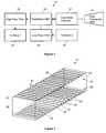
- FIG. 1is a block diagram of an antenna system employing a dual band orthomode transducer, according to an embodiment of the present invention
- FIG. 2is a perspective view of a dual band polarizer used in the antenna system shown in FIG. 1, according to the invention
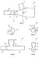
- FIG. 3is a cross-sectional view of a dual-band orthomode transducer that can be used in the antenna system shown in FIG. 1, according to one embodiment of the present invention
- FIG. 4is a cross-sectional view through line 4 — 4 of the orthomode transducer shown in FIG. 3;
- FIG. 5is a cross-sectional view through line 5 — 5 of the orthomode transducer shown in FIG. 3;
- FIG. 6is a cross-sectional view of a dual-band orthomode transducer that can be used in the antenna system shown in FIG. 1, according to another embodiment of the present invention.
- FIG. 7is an end view of the orthomode transducer shown in FIG. 6 .
- FIG. 1is a block diagram of an antenna system 10 employing a dual band feed network, according to the invention.
- the antenna system 10includes a dual band feed horn 14 that receives a satellite uplink signal at a particular frequency band, for example, 28-30 GHz or 40 GHz, and transmits a downlink signal at another frequency band, for example, 18.3-20.3 GHz. Only a single feed horn is shown in the antenna system 10 , with the understanding that the antenna system 10 would include an array of feed horns arranged in a desirable manner depending on the particular application.
- the horn 14is shown as a square or rectangular feed horn, but is intended to represent any feed horn operable in dual frequency bands having any suitable shape, including circular or elliptical shapes.
- the antenna system 10may also employ reflectors and the like for collecting and directing the uplink and downlink signals, depending on the particular application.
- the antenna system 10may also employ reflectors and the like for collecting and directing the uplink and downlink signals, depending on the particular application.
- the satellite uplink and downlink signalsare circularly polarized so that the orientation of the antenna elements relative to the signal can be arbitrary.
- the use of RHCP and LHCP signalsis important in high density applications for cell distinction, such as for cellular telephone applications.
- Polarizersare necessary after the feed horn 14 to convert the downlink signal from a linearly polarized signal to a circularly polarized signal, and for converting the uplink signal from a circularly polarized signal to a linearly polarized signal.
- a dual band polarizer 12performs this function for both the uplink and downlink frequency bands, either separately in time or simultaneously. Particularly, circularly polarized signals received on the satellite uplink by the dual frequency feed horn 14 are converted to a linearly polarized signal by the polarizer 12 , and the linearly polarized signals to be transmitted on the satellite downlink are converted to circularly polarized signals by the polarizer 12 before being sent to the feed horn 14 .
- the orientation of the dual band polarizer 12 relative to the signaldetermines whether LHCP or RHCP signals are converted to vertically or horizontally linearly polarized signals.
- the uplink and downlink signals at the separate frequency bandsmust be separated between the polarizer 12 and the reception and transmission circuitry.
- a diplexerwas used for this purpose.
- the diplexeris a complicated waveguide device that includes many signal ports, and is limited in its effectiveness to separate the signals.
- a dual-band orthomode transducer (OMT) 16is used to separate the signals into their respective frequency bands.
- the uplink signalincludes both vertically and horizontally linearly polarized components after passing through the polarizer 12
- the downlink signalincludes vertically and horizontally linearly polarized components when it enters the polarizer 12 .
- the OMT 16separates the signals by whether they are vertically polarized or horizontally polarized.
- the OMT 16is a waveguide device that includes waveguides ports and openings critically located to separate the vertical and horizontally polarized signals.
- the OMT 16has a reduced number of waveguides over known frequency separating devices, and provides dual band separation in a more desirable manner.
- the uplink and downlink signalsare at different frequencies.
- the OMT 16can separate vertically and horizontally polarized signals having the same frequency.
- the uplink signalsare directed to a high pass filter 18 that passes the uplink frequency band, and then to receiver circuitry 20 .
- the downlink signal generated by transmission circuitry 52is sent to a low pass filter 54 that passes the downlink frequency band, and then to the OMT 16 .
- the filters 18 and 24provide increased signal isolation.
- FIG. 2is a perspective view of the polarizer 12 .
- the polarizer 12is a hollow, square waveguide 22 that includes a first corrugated structure 24 extending from one sidewall 26 of the waveguide 22 , and a second corrugated structure 28 extending from an opposing sidewall 30 of the waveguide 22 .
- the corrugated structures 24 and 28are Identical, and therefore only the corrugated structure 28 will be described herein with the understanding that the corrugated structure 24 is the same.
- the corrugated structure 28includes a plurality of parallel ribs 32 defining spaces 34 therebetween. The width of the ribs 32 and the width of the spaces 34 remain constant along the length of the waveguide 22 .
- each of the ribs 32 from the wall 30is such that the corrugated structure 28 has a tapered configuration from one end 38 of the waveguide 22 to a center of the waveguide 22 , and from the center of the waveguide 22 to an opposite end 40 of the waveguide 22 .
- the height of the ribs 32 proximate the ends 38 and 40are at their lowest, and the height of the ribs 32 get progressively taller in a sequential manner towards the center of the waveguide 22 .
- the center rib 42has the largest height. This tapering of the height of the ribs 32 significantly eliminates reflections of the signal that may occur from discontinuities within the waveguide 22 .
- the other opposing side walls 44 and 46 of the waveguide 22are smooth. Further details of the polarizer 12 can be found in patent application Ser. No. 09/860,045.
- the signal propagating through the waveguide 22has orthogonal E x and E y field components.
- the E-field component that is perpendicular to the ribs 32interacts therewith and is delayed relative to the E-field component that is parallel or transverse to the ribs 32 and does not interact with the ribs 32 .
- the spaces 34 between the ribs 32act as waveguides that create a phase delay between the E x and E y field components. This delay causes the signal to rotate if the input signal is linearly polarized.
- the length of the waveguide 22is selected so that the E-field components end up out of phase by 90 degrees at the output end creating circular polarization.
- the orientation of the E x , and E y field components relative to the ribs 32determines which way the signal will rotate and whether the signal will be an RHCP or an LHCP signal.
- the E-field components of the linearly polarized downlink signalare oriented at an angle 45 degrees relative to perpendicular sides of the waveguide 22 .
- the ribs 32can speed up the E-field component that interacts with the ribs 32 to also create a phase discrepancy between the field components.
- the delay caused by the ribs 32matches the phases of the E-field components so that by the time they reach the opposite end of the waveguide 22 , they are in phase with each other making the signal linearly polarized.
- the dimensions of the waveguide 22 and the dimensions and spacing of the ribs 32are selected so that the lowest fundamental mode of the signal propagates through the waveguide 22 , and the phase relationship between the E-field components are 90 degrees apart, as described above. These parameters are also dependent on the speed of the signal propagating through the waveguide 22 that is also frequency dependent. For dual band polarization conversion, these dimensions are selected so that the higher frequency band, here 30 or 40 GHz, will be polarized in the desirable manner. Then, the dimensions are optimized for the lower frequency band, here 20 GHz.
- the dimensions of the waveguide 22are selected so that the components of the E-field are 90 degrees out of phase with each other for the high frequency, and then these values are slightly varied relative to each other to make the E-field components of the lower frequency band to also be 90 degrees out of phase with each other.
- This design criteriais possible because the lower frequency band is a subset of the higher frequency band.
- the spacing between the ribswas typically selected to be one-quarter of a wavelength of the center of the frequency band of interest. Typically only a few corrugations were necessary to perform the polarization conversion. However, in the design disclosed herein, that operates in two bands, the number of corrugations required is greater, typically on order of more than five.
- the width of the walls 26 , 30 , 44 and 46 of the waveguide 22are 0.456 inches
- the thickness of the ribs 32is 0.018 inches
- the space 34 between the ribs 32is 0.073 inches
- the number of ribs 32 and the number of spaces 34 between the ribs 32is thirty-nine
- the length of the waveguide 22is 1.802 inches.
- FIG. 3is a cross-sectional view of a dual-band orthomode transducer 60 that can be used as the transducer 16 discussed above.
- FIG. 4is a cross-sectional view of the transducer 60 through line 4 — 4 and
- FIG. 5is a cross-sectional view of the transducer 60 through line 5 — 5 in FIG. 3 .
- the transducer 60is a cylindrical waveguide device that includes a widened portion 62 at one end of the transducer 60 and a narrowed portion 64 at an opposite end of the transducer 60 , where the portions 62 and 64 are connected together by a conical section 66 .
- Two rectangular waveguides 70 and 72are connected to the conical portion 66 by narrowed irises 74 and 76 , respectively. Additionally, a rectangular waveguide 78 is attached to the narrowed cylindrical portion 64 by a narrowed iris 80 , and a rectangular waveguide 68 is connected to the end of the waveguide 64 by a narrowed iris 82 .
- the present embodimentmay be used for either single or dual polarized feed networks. By terminating the appropriate ports in a matched load or by selection of the rectangular waveguide dimensions such that ports 76 and 80 are eliminated, the OMT in this embodiment is for single polarization. Use “as is” results in dual polarization operation.
- the signals received by the feed horn 14propagate through the dual-band polarizer 12 and enter the end portion 62 of the transducer 60 .
- the signals from the polarizer 12include both horizontal and vertically linearly polarized components.
- the orientation and configuration of the transducer 60decouples the horizontally and vertically polarized components so that one of the horizontally or vertically polarized components propagates through the iris 82 and into the waveguide 68 , and the other horizontally or vertically polarized component propagates through the iris 80 and into the waveguide 78 .
- the separated signalsare then applied to the high pass filter 18 and to the receiver circuitry 20 .
- the irises 80 and 82provide phase and impedance matching between the two components of the signal. In an alternate variation, the irises 80 and 82 can be stepped transformers.
- Signals from the transmit circuitry 52are separated by their horizontal and linearly polarized components, and separately enter the transducer 60 through the waveguides 70 and 72 .
- the irises 74 and 76provide phase and impedance matching between the waveguides 70 and 72 , and the transducer 60 couples the signals together in phase to be sent to the polarizer 12 as a combined signal having both linearly and horizontally polarized components.
- FIG. 6shows a cross-sectional view of a dual-band orthomode transducer 90 that can also be used as the dual-band transducer 16 .
- FIG. 7is an end view of the transducer 90 .
- the transducer 90includes a cylindrical waveguide 92 extending the length of the transducer 90 .
- a rectangular waveguide 94is connected to the circular waveguide 92 at one end of the transducer 90 by a stepped transformer 98 .
- a rectangular waveguide 102is connected to a sidewall of the circular waveguide 92 by a stepped transformer 104 .
- the transformers 98 and 104provide impedance matching for the frequency of the uplink and downlink signals.
- the transducer 90is a three port device, where the waveguides 94 and 102 accommodate the uplink and/or downlink signals, respectively and/or vise versa at the different frequency bands.
- the uplink signals received from the polarizer 12propagate through the waveguide 92 .
- the horizontally and vertically polarized components of the uplink signalare separated so that one of the two components enters the waveguide 94 through the transformer 98 , and the other of the components enters the waveguide 102 through the transformer 104 .
- the downlink signals to be transmitted by the feedhorn 14are received by the transducer 90 also through the waveguides 94 and 102 .
- One of either the horizontally or vertically polarized componentspropagate through the waveguide 94 , and the other of the horizontally or vertically components propagate through the waveguide 102 .
- the waveguide 92 phasematches and couples the components together so that the horizontal and vertical components of the signal are sent to the polarizer 12 .
Landscapes
- Waveguide Aerials (AREA)
- Waveguide Switches, Polarizers, And Phase Shifters (AREA)
Abstract
Description
Claims (15)
Priority Applications (1)
| Application Number | Priority Date | Filing Date | Title |
|---|---|---|---|
| US09/860,105US6473053B1 (en) | 2001-05-17 | 2001-05-17 | Dual frequency single polarization feed network |
Applications Claiming Priority (1)
| Application Number | Priority Date | Filing Date | Title |
|---|---|---|---|
| US09/860,105US6473053B1 (en) | 2001-05-17 | 2001-05-17 | Dual frequency single polarization feed network |
Publications (2)
| Publication Number | Publication Date |
|---|---|
| US6473053B1true US6473053B1 (en) | 2002-10-29 |
| US20020171597A1 US20020171597A1 (en) | 2002-11-21 |
Family
ID=25332501
Family Applications (1)
| Application Number | Title | Priority Date | Filing Date |
|---|---|---|---|
| US09/860,105Expired - LifetimeUS6473053B1 (en) | 2001-05-17 | 2001-05-17 | Dual frequency single polarization feed network |
Country Status (1)
| Country | Link |
|---|---|
| US (1) | US6473053B1 (en) |
Cited By (17)
| Publication number | Priority date | Publication date | Assignee | Title |
|---|---|---|---|---|
| US20030006866A1 (en)* | 2000-06-05 | 2003-01-09 | Naofumi Yoneda | Waveguide group branching filter |
| US20040160292A1 (en)* | 2003-02-18 | 2004-08-19 | Chen Ming H. | Orthomode Transducer Having Improved Cross-Polarization Suppression and Method of Manufacture |
| US20060145782A1 (en)* | 2005-01-04 | 2006-07-06 | Kai Liu | Multiplexers employing bandpass-filter architectures |
| WO2006127610A3 (en)* | 2005-05-23 | 2007-03-15 | Gen Dynamics Satcom Technologi | Tri-band circularly-polarized antenna for a satellite communications ground terminal |
| US20080297428A1 (en)* | 2006-02-24 | 2008-12-04 | Northrop Grumman Corporation | High-power dual-frequency coaxial feedhorn antenna |
| US20100081373A1 (en)* | 2008-10-01 | 2010-04-01 | Lockheed Martin Corporation | Satellite feed assembly with integrated filters and test couplers |
| US7808427B1 (en) | 2009-05-28 | 2010-10-05 | Raytheon Company | Radar system having dual band polarization versatile active electronically scanned lens array |
| CN102842765A (en)* | 2012-08-30 | 2012-12-26 | 南京信息工程大学 | Novel high-isolation common-frequency dual-polarization horn antenna |
| CN103779663A (en)* | 2014-02-26 | 2014-05-07 | 南京信息工程大学 | Dual-frequency orthogonal polarization high-isolation horn antenna |
| CN103956548A (en)* | 2014-05-23 | 2014-07-30 | 成都赛纳赛德科技有限公司 | E plane wave separator |
| US20150015440A1 (en)* | 2013-07-11 | 2015-01-15 | Honeywell International Inc. | Frequency selective polarizer |
| WO2015044476A1 (en) | 2013-09-24 | 2015-04-02 | Universidad Politécnica de Madrid | Feeder line of an antenna with a double frequency band and different circular polarisation in each band |
| US20150381265A1 (en)* | 2014-06-30 | 2015-12-31 | Viasat, Inc. | Systems and methods for polarization control |
| US20200227832A1 (en)* | 2017-10-03 | 2020-07-16 | Murata Manufacturing Co., Ltd. | Antenna module and method for inspecting antenna module |
| US10892549B1 (en) | 2020-02-28 | 2021-01-12 | Northrop Grumman Systems Corporation | Phased-array antenna system |
| US11329391B2 (en)* | 2015-02-27 | 2022-05-10 | Viasat, Inc. | Enhanced directivity feed and feed array |
| CN114976626A (en)* | 2022-06-30 | 2022-08-30 | 休斯网络技术有限公司 | Ku and Ka dual-band integrated feed source and satellite antenna in satellite communication |
Families Citing this family (6)
| Publication number | Priority date | Publication date | Assignee | Title |
|---|---|---|---|---|
| KR100763579B1 (en)* | 2006-11-17 | 2007-10-04 | 한국전자통신연구원 | Comb polarizer suitable for millimeter wave band applications |
| US7659861B2 (en)* | 2008-01-14 | 2010-02-09 | Wistron Neweb Corp. | Dual frequency feed assembly |
| WO2010056609A2 (en)* | 2008-11-11 | 2010-05-20 | Viasat, Inc. | Integrated orthomode transducer |
| US8254851B2 (en)* | 2008-11-11 | 2012-08-28 | Viasat, Inc. | Integrated orthomode transducer |
| US20110109501A1 (en)* | 2009-11-06 | 2011-05-12 | Viasat, Inc. | Automated beam peaking satellite ground terminal |
| US8981886B2 (en) | 2009-11-06 | 2015-03-17 | Viasat, Inc. | Electromechanical polarization switch |
Citations (9)
| Publication number | Priority date | Publication date | Assignee | Title |
|---|---|---|---|---|
| US3731235A (en)* | 1971-11-03 | 1973-05-01 | Gte Sylvania Inc | Dual polarized diplexer |
| US4228410A (en)* | 1979-01-19 | 1980-10-14 | Ford Aerospace & Communications Corp. | Microwave circular polarizer |
| US4847574A (en)* | 1986-09-12 | 1989-07-11 | Gauthier Simon R | Wide bandwidth multiband feed system with polarization diversity |
| US5280297A (en)* | 1992-04-06 | 1994-01-18 | General Electric Co. | Active reflectarray antenna for communication satellite frequency re-use |
| US5635944A (en)* | 1994-12-15 | 1997-06-03 | Unisys Corporation | Multi-band antenna feed with switchably shared I/O port |
| US6094175A (en)* | 1998-11-17 | 2000-07-25 | Hughes Electronics Corporation | Omni directional antenna |
| US6163304A (en)* | 1999-03-16 | 2000-12-19 | Trw Inc. | Multimode, multi-step antenna feed horn |
| US6323819B1 (en)* | 2000-10-05 | 2001-11-27 | Harris Corporation | Dual band multimode coaxial tracking feed |
| US6329957B1 (en)* | 1998-10-30 | 2001-12-11 | Austin Information Systems, Inc. | Method and apparatus for transmitting and receiving multiple frequency bands simultaneously |
- 2001
- 2001-05-17USUS09/860,105patent/US6473053B1/ennot_activeExpired - Lifetime
Patent Citations (9)
| Publication number | Priority date | Publication date | Assignee | Title |
|---|---|---|---|---|
| US3731235A (en)* | 1971-11-03 | 1973-05-01 | Gte Sylvania Inc | Dual polarized diplexer |
| US4228410A (en)* | 1979-01-19 | 1980-10-14 | Ford Aerospace & Communications Corp. | Microwave circular polarizer |
| US4847574A (en)* | 1986-09-12 | 1989-07-11 | Gauthier Simon R | Wide bandwidth multiband feed system with polarization diversity |
| US5280297A (en)* | 1992-04-06 | 1994-01-18 | General Electric Co. | Active reflectarray antenna for communication satellite frequency re-use |
| US5635944A (en)* | 1994-12-15 | 1997-06-03 | Unisys Corporation | Multi-band antenna feed with switchably shared I/O port |
| US6329957B1 (en)* | 1998-10-30 | 2001-12-11 | Austin Information Systems, Inc. | Method and apparatus for transmitting and receiving multiple frequency bands simultaneously |
| US6094175A (en)* | 1998-11-17 | 2000-07-25 | Hughes Electronics Corporation | Omni directional antenna |
| US6163304A (en)* | 1999-03-16 | 2000-12-19 | Trw Inc. | Multimode, multi-step antenna feed horn |
| US6323819B1 (en)* | 2000-10-05 | 2001-11-27 | Harris Corporation | Dual band multimode coaxial tracking feed |
Cited By (30)
| Publication number | Priority date | Publication date | Assignee | Title |
|---|---|---|---|---|
| US20030006866A1 (en)* | 2000-06-05 | 2003-01-09 | Naofumi Yoneda | Waveguide group branching filter |
| US6847270B2 (en)* | 2000-06-05 | 2005-01-25 | Mitsubishi Denki Kabushiki Kaisha | Waveguide group branching filter |
| US20040160292A1 (en)* | 2003-02-18 | 2004-08-19 | Chen Ming H. | Orthomode Transducer Having Improved Cross-Polarization Suppression and Method of Manufacture |
| US6842085B2 (en) | 2003-02-18 | 2005-01-11 | Victory Microwave Corporation | Orthomode transducer having improved cross-polarization suppression and method of manufacture |
| US7606184B2 (en) | 2005-01-04 | 2009-10-20 | Tdk Corporation | Multiplexers employing bandpass-filter architectures |
| US20060145782A1 (en)* | 2005-01-04 | 2006-07-06 | Kai Liu | Multiplexers employing bandpass-filter architectures |
| WO2006127610A3 (en)* | 2005-05-23 | 2007-03-15 | Gen Dynamics Satcom Technologi | Tri-band circularly-polarized antenna for a satellite communications ground terminal |
| US20080297428A1 (en)* | 2006-02-24 | 2008-12-04 | Northrop Grumman Corporation | High-power dual-frequency coaxial feedhorn antenna |
| US7511678B2 (en) | 2006-02-24 | 2009-03-31 | Northrop Grumman Corporation | High-power dual-frequency coaxial feedhorn antenna |
| US20100081373A1 (en)* | 2008-10-01 | 2010-04-01 | Lockheed Martin Corporation | Satellite feed assembly with integrated filters and test couplers |
| WO2010039396A1 (en)* | 2008-10-01 | 2010-04-08 | Lockheed Martin Corporation | Satellite feed assembly with integrated filters and test couplers |
| US7808427B1 (en) | 2009-05-28 | 2010-10-05 | Raytheon Company | Radar system having dual band polarization versatile active electronically scanned lens array |
| CN102842765A (en)* | 2012-08-30 | 2012-12-26 | 南京信息工程大学 | Novel high-isolation common-frequency dual-polarization horn antenna |
| US20150015440A1 (en)* | 2013-07-11 | 2015-01-15 | Honeywell International Inc. | Frequency selective polarizer |
| US9490545B2 (en)* | 2013-07-11 | 2016-11-08 | Honeywell International Inc. | Frequency selective polarizer |
| WO2015044476A1 (en) | 2013-09-24 | 2015-04-02 | Universidad Politécnica de Madrid | Feeder line of an antenna with a double frequency band and different circular polarisation in each band |
| CN103779663A (en)* | 2014-02-26 | 2014-05-07 | 南京信息工程大学 | Dual-frequency orthogonal polarization high-isolation horn antenna |
| CN103779663B (en)* | 2014-02-26 | 2016-08-17 | 南京信息工程大学 | Double frequency cross polarization high-isolation electromagnetic horn |
| CN103956548A (en)* | 2014-05-23 | 2014-07-30 | 成都赛纳赛德科技有限公司 | E plane wave separator |
| CN103956548B (en)* | 2014-05-23 | 2016-03-23 | 成都赛纳赛德科技有限公司 | E face channel-splitting filter |
| US20150381265A1 (en)* | 2014-06-30 | 2015-12-31 | Viasat, Inc. | Systems and methods for polarization control |
| US9571183B2 (en)* | 2014-06-30 | 2017-02-14 | Viasat, Inc. | Systems and methods for polarization control |
| US11329391B2 (en)* | 2015-02-27 | 2022-05-10 | Viasat, Inc. | Enhanced directivity feed and feed array |
| US11996618B2 (en) | 2015-02-27 | 2024-05-28 | Viasat, Inc. | Enhanced directivity feed and feed array |
| US20200227832A1 (en)* | 2017-10-03 | 2020-07-16 | Murata Manufacturing Co., Ltd. | Antenna module and method for inspecting antenna module |
| US11495874B2 (en)* | 2017-10-03 | 2022-11-08 | Murata Manufacturing Co., Ltd. | Antenna module and method for inspecting antenna module |
| US12142816B2 (en) | 2017-10-03 | 2024-11-12 | Murata Manufacturing Co., Ltd. | Antenna module and method for inspecting antenna module |
| US10892549B1 (en) | 2020-02-28 | 2021-01-12 | Northrop Grumman Systems Corporation | Phased-array antenna system |
| US11251524B1 (en) | 2020-02-28 | 2022-02-15 | Northrop Grumman Systems Corporation | Phased-array antenna system |
| CN114976626A (en)* | 2022-06-30 | 2022-08-30 | 休斯网络技术有限公司 | Ku and Ka dual-band integrated feed source and satellite antenna in satellite communication |
Also Published As
| Publication number | Publication date |
|---|---|
| US20020171597A1 (en) | 2002-11-21 |
Similar Documents
| Publication | Publication Date | Title |
|---|---|---|
| US6473053B1 (en) | Dual frequency single polarization feed network | |
| US11569554B2 (en) | Orthomode transducer | |
| US6566976B2 (en) | Symmetric orthomode coupler for cellular application | |
| US6563470B2 (en) | Dual band frequency polarizer using corrugated geometry profile | |
| US4847574A (en) | Wide bandwidth multiband feed system with polarization diversity | |
| US7239285B2 (en) | Circular polarity elliptical horn antenna | |
| US7642982B2 (en) | Multi-band circular polarity elliptical horn antenna | |
| US4410866A (en) | Antenna transducer for a transmission-reception antenna | |
| US20150097747A1 (en) | Antenna system for simultaneous triple-band satellite communication | |
| US6504514B1 (en) | Dual-band equal-beam reflector antenna system | |
| EP3583661B1 (en) | Compact dual circular polarization multi-band waveguide feed network | |
| US6577207B2 (en) | Dual-band electromagnetic coupler | |
| US7659861B2 (en) | Dual frequency feed assembly | |
| KR100815154B1 (en) | Feeding device for satellite communication multiband antenna with waveguide structure | |
| US6529098B2 (en) | Transmitting and receiving apparatus for satellite communication via dual-polarized signals | |
| JPH1117402A (en) | Antenna source for sending and receiving microwave | |
| US6313714B1 (en) | Waveguide coupler | |
| US5534881A (en) | Microwave filter assembly having a nonsymmetrical waveguide and an antenna | |
| US6657516B1 (en) | Wideband TE11 mode coaxial turnstile junction | |
| US6046702A (en) | Probe coupled, multi-band combiner/divider | |
| US4366453A (en) | Orthogonal mode transducer having interface plates at the junction of the waveguides | |
| US11387563B2 (en) | Radiofrequency exciter of a receiving and transmitting antenna | |
| CA2567417C (en) | Circular polarity elliptical horn antenna | |
| CA2967966C (en) | Compact multifrequency dual-polarization radiofrequency exciter for a primary antenna source and a primary antenna source equipped with such a radiofrequency exciter | |
| KR950004803B1 (en) | Circularly Polarized Diplexer Device for 4 / 6GHz Satellite Communication |
Legal Events
| Date | Code | Title | Description |
|---|---|---|---|
| AS | Assignment | Owner name:TRW INC., CALIFORNIA Free format text:ASSIGNMENT OF ASSIGNORS INTEREST;ASSIGNORS:KRISHMAR-JUNKER, GREGORY P.;CHANDLER, CHARLES W.;EM, MAKKALON;REEL/FRAME:011827/0161 Effective date:20010505 | |
| STCF | Information on status: patent grant | Free format text:PATENTED CASE | |
| AS | Assignment | Owner name:NORTHROP GRUMMAN CORPORATION, CALIFORNIA Free format text:ASSIGNMENT OF ASSIGNORS INTEREST;ASSIGNOR:TRW, INC. N/K/A NORTHROP GRUMMAN SPACE AND MISSION SYSTEMS CORPORATION, AN OHIO CORPORATION;REEL/FRAME:013751/0849 Effective date:20030122 Owner name:NORTHROP GRUMMAN CORPORATION,CALIFORNIA Free format text:ASSIGNMENT OF ASSIGNORS INTEREST;ASSIGNOR:TRW, INC. N/K/A NORTHROP GRUMMAN SPACE AND MISSION SYSTEMS CORPORATION, AN OHIO CORPORATION;REEL/FRAME:013751/0849 Effective date:20030122 | |
| FPAY | Fee payment | Year of fee payment:4 | |
| FEPP | Fee payment procedure | Free format text:PAYOR NUMBER ASSIGNED (ORIGINAL EVENT CODE: ASPN); ENTITY STATUS OF PATENT OWNER: LARGE ENTITY | |
| AS | Assignment | Owner name:NORTHROP GRUMMAN SPACE & MISSION SYSTEMS CORP.,CAL Free format text:ASSIGNMENT OF ASSIGNORS INTEREST;ASSIGNOR:NORTHROP GRUMMAN CORPORTION;REEL/FRAME:023699/0551 Effective date:20091125 Owner name:NORTHROP GRUMMAN SPACE & MISSION SYSTEMS CORP., CA Free format text:ASSIGNMENT OF ASSIGNORS INTEREST;ASSIGNOR:NORTHROP GRUMMAN CORPORTION;REEL/FRAME:023699/0551 Effective date:20091125 | |
| AS | Assignment | Owner name:NORTHROP GRUMMAN SYSTEMS CORPORATION,CALIFORNIA Free format text:ASSIGNMENT OF ASSIGNORS INTEREST;ASSIGNOR:NORTHROP GRUMMAN SPACE & MISSION SYSTEMS CORP.;REEL/FRAME:023915/0446 Effective date:20091210 Owner name:NORTHROP GRUMMAN SYSTEMS CORPORATION, CALIFORNIA Free format text:ASSIGNMENT OF ASSIGNORS INTEREST;ASSIGNOR:NORTHROP GRUMMAN SPACE & MISSION SYSTEMS CORP.;REEL/FRAME:023915/0446 Effective date:20091210 | |
| FPAY | Fee payment | Year of fee payment:8 | |
| FPAY | Fee payment | Year of fee payment:12 |