US6471930B2 - Silicon oxide particles - Google Patents
Silicon oxide particlesDownload PDFInfo
- Publication number
- US6471930B2 US6471930B2US09/731,286US73128600AUS6471930B2US 6471930 B2US6471930 B2US 6471930B2US 73128600 AUS73128600 AUS 73128600AUS 6471930 B2US6471930 B2US 6471930B2
- Authority
- US
- United States
- Prior art keywords
- particles
- percent
- average diameter
- polishing
- laser
- Prior art date
- Legal status (The legal status is an assumption and is not a legal conclusion. Google has not performed a legal analysis and makes no representation as to the accuracy of the status listed.)
- Expired - Lifetime
Links
Images


Classifications
- B—PERFORMING OPERATIONS; TRANSPORTING
- B01—PHYSICAL OR CHEMICAL PROCESSES OR APPARATUS IN GENERAL
- B01J—CHEMICAL OR PHYSICAL PROCESSES, e.g. CATALYSIS OR COLLOID CHEMISTRY; THEIR RELEVANT APPARATUS
- B01J12/00—Chemical processes in general for reacting gaseous media with gaseous media; Apparatus specially adapted therefor
- B01J12/005—Chemical processes in general for reacting gaseous media with gaseous media; Apparatus specially adapted therefor carried out at high temperatures, e.g. by pyrolysis
- C—CHEMISTRY; METALLURGY
- C09—DYES; PAINTS; POLISHES; NATURAL RESINS; ADHESIVES; COMPOSITIONS NOT OTHERWISE PROVIDED FOR; APPLICATIONS OF MATERIALS NOT OTHERWISE PROVIDED FOR
- C09K—MATERIALS FOR MISCELLANEOUS APPLICATIONS, NOT PROVIDED FOR ELSEWHERE
- C09K3/00—Materials not provided for elsewhere
- C09K3/14—Anti-slip materials; Abrasives
- B—PERFORMING OPERATIONS; TRANSPORTING
- B01—PHYSICAL OR CHEMICAL PROCESSES OR APPARATUS IN GENERAL
- B01J—CHEMICAL OR PHYSICAL PROCESSES, e.g. CATALYSIS OR COLLOID CHEMISTRY; THEIR RELEVANT APPARATUS
- B01J12/00—Chemical processes in general for reacting gaseous media with gaseous media; Apparatus specially adapted therefor
- B01J12/02—Chemical processes in general for reacting gaseous media with gaseous media; Apparatus specially adapted therefor for obtaining at least one reaction product which, at normal temperature, is in the solid state
- B—PERFORMING OPERATIONS; TRANSPORTING
- B01—PHYSICAL OR CHEMICAL PROCESSES OR APPARATUS IN GENERAL
- B01J—CHEMICAL OR PHYSICAL PROCESSES, e.g. CATALYSIS OR COLLOID CHEMISTRY; THEIR RELEVANT APPARATUS
- B01J19/00—Chemical, physical or physico-chemical processes in general; Their relevant apparatus
- B01J19/08—Processes employing the direct application of electric or wave energy, or particle radiation; Apparatus therefor
- B01J19/12—Processes employing the direct application of electric or wave energy, or particle radiation; Apparatus therefor employing electromagnetic waves
- B01J19/121—Coherent waves, e.g. laser beams
- B—PERFORMING OPERATIONS; TRANSPORTING
- B82—NANOTECHNOLOGY
- B82Y—SPECIFIC USES OR APPLICATIONS OF NANOSTRUCTURES; MEASUREMENT OR ANALYSIS OF NANOSTRUCTURES; MANUFACTURE OR TREATMENT OF NANOSTRUCTURES
- B82Y30/00—Nanotechnology for materials or surface science, e.g. nanocomposites
- C—CHEMISTRY; METALLURGY
- C01—INORGANIC CHEMISTRY
- C01B—NON-METALLIC ELEMENTS; COMPOUNDS THEREOF; METALLOIDS OR COMPOUNDS THEREOF NOT COVERED BY SUBCLASS C01C
- C01B33/00—Silicon; Compounds thereof
- C01B33/113—Silicon oxides; Hydrates thereof
- C01B33/12—Silica; Hydrates thereof, e.g. lepidoic silicic acid
- C01B33/18—Preparation of finely divided silica neither in sol nor in gel form; After-treatment thereof
- C01B33/181—Preparation of finely divided silica neither in sol nor in gel form; After-treatment thereof by a dry process
- C01B33/183—Preparation of finely divided silica neither in sol nor in gel form; After-treatment thereof by a dry process by oxidation or hydrolysis in the vapour phase of silicon compounds such as halides, trichlorosilane, monosilane
- C—CHEMISTRY; METALLURGY
- C09—DYES; PAINTS; POLISHES; NATURAL RESINS; ADHESIVES; COMPOSITIONS NOT OTHERWISE PROVIDED FOR; APPLICATIONS OF MATERIALS NOT OTHERWISE PROVIDED FOR
- C09G—POLISHING COMPOSITIONS; SKI WAXES
- C09G1/00—Polishing compositions
- C09G1/02—Polishing compositions containing abrasives or grinding agents
- C—CHEMISTRY; METALLURGY
- C09—DYES; PAINTS; POLISHES; NATURAL RESINS; ADHESIVES; COMPOSITIONS NOT OTHERWISE PROVIDED FOR; APPLICATIONS OF MATERIALS NOT OTHERWISE PROVIDED FOR
- C09K—MATERIALS FOR MISCELLANEOUS APPLICATIONS, NOT PROVIDED FOR ELSEWHERE
- C09K3/00—Materials not provided for elsewhere
- C09K3/14—Anti-slip materials; Abrasives
- C09K3/1409—Abrasive particles per se
- C—CHEMISTRY; METALLURGY
- C09—DYES; PAINTS; POLISHES; NATURAL RESINS; ADHESIVES; COMPOSITIONS NOT OTHERWISE PROVIDED FOR; APPLICATIONS OF MATERIALS NOT OTHERWISE PROVIDED FOR
- C09K—MATERIALS FOR MISCELLANEOUS APPLICATIONS, NOT PROVIDED FOR ELSEWHERE
- C09K3/00—Materials not provided for elsewhere
- C09K3/14—Anti-slip materials; Abrasives
- C09K3/1454—Abrasive powders, suspensions and pastes for polishing
- C09K3/1463—Aqueous liquid suspensions
- C—CHEMISTRY; METALLURGY
- C01—INORGANIC CHEMISTRY
- C01P—INDEXING SCHEME RELATING TO STRUCTURAL AND PHYSICAL ASPECTS OF SOLID INORGANIC COMPOUNDS
- C01P2002/00—Crystal-structural characteristics
- C01P2002/50—Solid solutions
- C—CHEMISTRY; METALLURGY
- C01—INORGANIC CHEMISTRY
- C01P—INDEXING SCHEME RELATING TO STRUCTURAL AND PHYSICAL ASPECTS OF SOLID INORGANIC COMPOUNDS
- C01P2004/00—Particle morphology
- C01P2004/30—Particle morphology extending in three dimensions
- C01P2004/32—Spheres
- C—CHEMISTRY; METALLURGY
- C01—INORGANIC CHEMISTRY
- C01P—INDEXING SCHEME RELATING TO STRUCTURAL AND PHYSICAL ASPECTS OF SOLID INORGANIC COMPOUNDS
- C01P2004/00—Particle morphology
- C01P2004/51—Particles with a specific particle size distribution
- C—CHEMISTRY; METALLURGY
- C01—INORGANIC CHEMISTRY
- C01P—INDEXING SCHEME RELATING TO STRUCTURAL AND PHYSICAL ASPECTS OF SOLID INORGANIC COMPOUNDS
- C01P2004/00—Particle morphology
- C01P2004/60—Particles characterised by their size
- C01P2004/62—Submicrometer sized, i.e. from 0.1-1 micrometer
- C—CHEMISTRY; METALLURGY
- C01—INORGANIC CHEMISTRY
- C01P—INDEXING SCHEME RELATING TO STRUCTURAL AND PHYSICAL ASPECTS OF SOLID INORGANIC COMPOUNDS
- C01P2004/00—Particle morphology
- C01P2004/60—Particles characterised by their size
- C01P2004/64—Nanometer sized, i.e. from 1-100 nanometer
Definitions
- the inventionrelates to abrasive compositions useful for surface polishing, especially mechanochemical polishing, and methods for producing abrasive particles.
- polishing technologycan employ mechanochemical polishing involving a polishing composition that acts by way of a chemical interaction of the substrate with the polishing agents as well as an abrasive effective for mechanical smoothing of the surface.
- Improved polishing compositionsare described for smoothing surfaces to very low tolerances.
- the polishing compositionsare based on small particles with a very narrow distribution of particle diameters to provide for more control over the polishing process.
- a collection of preferred particleshave effectively no particles with significantly larger diameters.
- the preferred particleshave a very high level of purity with respect to a single crystalline phase.
- Laser pyrolysisprovides for the production of preferred particles. Laser pyrolysis not only provides for the production of particles with preferred properties for abrasive applications but also for efficient and controlled production of the particles. These features provide for cost effective commercialization of the improved abrasive compositions.
- the inventionfeatures a composition comprising a dispersion of particles, the particles including metal compounds and having an average particle diameter from about 5 nm to about 200 nm and a distribution of diameters such that at least about 95 percent of the particles have a diameter greater than about 60 percent of the average diameter and less than about 140 percent of the average diameter.
- the particlescan be dispersed in an aqueous or nonaqueous solution.
- the particlespreferably comprise a composition selected from the group consisting of SiO 2 , SiC, TiO 2 , Fe 3 C, Fe 7 C 3 , Fe 2 O 3 , Fe 3 O 4 , MoS 2 , MoO 2 , WC, WO 3 and WS 2 .
- the particlespreferably have an average diameter less than about 100 nm.
- the inventionfeatures a composition
- a compositioncomprising a dispersion of particles, the particles including metal compounds with an average particle diameter from about 5 nm to about 200 nm and a single crystalline phase with a uniformity of at least about 90 percent by weight.
- the particlescan be dispersed in an aqueous or nonaqueous solution.
- the particlespreferably have a single phase uniformity of at least about 95 percent by weight, more preferably at least about 99 percent by weight and even more preferably at least about 99.9 percent by weight.
- the inventionfeatures a composition comprising a dispersion of particles, the particles including metal carbides or metal sulfides and having an average particle diameter from about 5 nm to about 200 nm.
- the inventionfeatures a method of smoothing a surface comprising the step of polishing the surface with a composition of the invention, as summarized above and further described below.
- the polishingcan be performed with a polishing pad and can involve a motorized polisher.
- the inventionfeatures a method of producing SiO 2 particles including the step of pyrolyzing a molecular stream comprising a silicon compound precursor, an oxidizing agent and a radiation absorbing gas in a reaction chamber, where the pyrolysis is driven by heat absorbed from a laser beam.
- the silicon compound precursorcan include a compound that is selected from the group consisting of CH 3 SiCl 3 .
- the laser beampreferably is supplied by a CO 2 laser.
- the molecular streampreferably is generated by a nozzle elongated in one dimension.
- the inventionfeatures a method of producing iron oxide particles comprising the step of pyrolyzing a molecular stream comprising a iron compound precursor, an oxidizing agent and a radiation absorbing gas in a reaction chamber, where the pyrolysis is driven by heat absorbed from a laser beam.
- the iron precursorcan comprise Fe(CO) 5 .
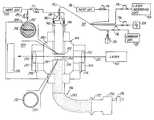
- FIG. 1is a schematic, sectional view of an embodiment of a laser pyrolysis apparatus taken through the middle of the laser radiation path.
- the upper insertis a bottom view of the injection nozzle, and the lower insert is a top view of the collection nozzle.
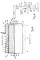
- FIG. 2is a schematic, perspective view of a reaction chamber of an alternative embodiment of the laser pyrolysis apparatus, where the materials of the chamber are depicted as transparent to reveal the interior of the apparatus.
- FIG. 3is a sectional view of the reaction chamber of FIG. 2 taken along line 3 — 3 .
- FIG. 4is a schematic, sectional view of an oven for heating vanadium oxide particles, in which the section is taken through the center of the quartz tube.
- Nanoscale particleswith a small distribution of particle diameters. These particles generally have a single crystalline phase and a high level of uniformity. These particles are useful as abrasives, especially for polishing hard surfaces that have restrictive tolerance requirements with respect to smoothness.
- the small diameters together with the narrow spread in distribution of diametersprovide for polishing to generate a surface with reduced degree of surface roughness.
- the particlescan be used in polishing compositions containing other polishing agents that supplement the abrasive properties of the particles alone.
- the polishing compositionscan be used for manual polishing or for polishing with a motorized polisher.
- Suitable abrasive particlesgenerally are ceramics, although not necessarily electrical insulators, and can include a variety of metal oxides, sulfides and carbides as well as silica compounds. Preferred particles are relatively hard.
- the particlecan include, for example, one of the following compounds: SiO 2 , SiC, TiO 2 , Fe 2 O 3 , Fe 3 O 4 , Fe 3 C, Fe 7 C 3 , MoS 2 , MoO 2 , WC, WO 3 , and WS 2 .
- a mixture of abrasive particles of different chemical compositioncan be used to form a polishing formulation. The appropriate composition of the abrasive particles depends on the composition of the substrate to be polished.
- Laser pyrolysisas described below, is an excellent process for efficiently producing suitable ceramic particles with a narrow distribution of average particle diameters.
- a basic feature of successful application of laser pyrolysis for the production of appropriate small scale particlesis production of a molecular stream containing a precursor compound, a radiation absorber and a reactant serving as an oxygen, sulfur or carbon source.
- the molecular streamis pyrolyzed by an intense laser beam. As the molecular stream leaves the laser beam, the particles are rapidly quenched.
- Laser pyrolysisprovides for formation of phases of metal compounds that may be difficult to form under thermodynamic equilibrium conditions.
- the particles produced by laser pyrolysisalso are suitable for optional further processing to alter and/or improve the properties of the particles.
- Laser pyrolysishas been discovered to be a valuable tool for the production of nanoscale silicon dioxide, silicon carbide and metal oxide, metal carbide and metal sulfide particles of interest.
- the particles produced by laser pyrolysisare a convenient material for further processing to expand the pathways for the production of desirable metal compound particles.
- laser pyrolysisalone or in combination with additional processes, a wide variety of silicon dioxide, silicon carbide and metal oxide, metal carbide and metal sulfide particles can be produced. In some cases, alternative production pathways can be followed to produce comparable particles.
- the reaction conditionsdetermine the qualities of the particles produced by laser pyrolysis.
- the reaction conditions for laser pyrolysiscan be controlled relatively precisely in order to produce particles with desired properties.
- the appropriate reaction conditions to produce a certain type of particlesgenerally depend on the design of the particular apparatus. Nevertheless, some general observations on the relationship between reaction conditions and the resulting particles can be made.
- Reactant gas flow rate and velocity of the reactant gas streamare inversely related to particle size so that increasing the reactant gas flow rate or velocity tends to result in smaller particle size. Also, the growth dynamics of the particles have a significant influence on the size of the resulting particles. In other words, different crystal forms of a product compound have a tendency to form different size particles from other crystal forms under relatively similar conditions. Laser power also influences particle size with increased laser power favoring larger particle formation for lower melting materials and smaller particle formation for higher melting materials.
- Appropriate precursor compoundsgenerally include metal or silicon compounds with reasonable vapor pressures, i.e., vapor pressures sufficient to get desired amounts of precursor vapor in the reactant stream.
- the vessel holding the precursor compoundscan be heated to increase the vapor pressure of the metal (silicon) compound precursor, if desired.
- Preferred silicon precursorsinclude, for example, CH 3 SiCl 3 .
- Preferred iron precursorsinclude, for example, Fe(CO) 5 .
- Preferred reactants serving as oxygen sourcesinclude, for example, O 2 , CO, CO 2 , O 3 and mixtures thereof.
- Preferred reactants serving as carbon sourcesinclude, for example, C 2 H 4 and C 6 H 6 .
- Preferred reactants serving as sulfur sourcesinclude, for example, H 2 S.
- the reactant compound from the oxygen, carbon or sulfur sourceshould not react significantly with the metal compound precursor prior to entering the reaction zone since this generally would result in the formation of large particles.
- Laser pyrolysiscan be performed with a variety of optical laser frequencies.
- Preferred lasersoperate in the infrared portion of the electromagnetic spectrum.
- CO 2 lasersare particularly preferred sources of laser light.
- Infrared absorbers for inclusion in the molecular streaminclude, for example, C 2 H 4 , NH 3 , SF 6 , SiH 4 and O 3 .
- O 3can act as both an infrared absorber and as an oxygen source.
- C 2 H 4can act as both a infrared absorber and as a carbon source.
- the radiation absorbersuch as the infrared absorber, absorbs energy from the radiation beam and distributes the energy to the other reactants to drive the pyrolysis.
- the energy absorbed from the radiation beamincreases the temperature at a tremendous rate, many times the rate that energy generally would be produced even by strongly exothermic reactions under controlled condition. While the process generally involves nonequilibrium conditions, the temperature can be described approximately based on the energy in the absorbing region.
- the laser pyrolysis processis qualitatively different from the process in a combustion reactor where an energy source initiates a reaction, but the reaction is driven by energy given off by an exothermic reaction.
- An inert shielding gascan be used to reduce the amount of reactant and product molecules contacting the reactant chamber components.
- Appropriate shielding gasesinclude, for example, Ar, He and N 2 .
- An appropriate laser pyrolysis apparatusgenerally includes a reaction chamber isolated from the ambient environment.
- a reactant inlet connected to a reactant supply systemproduces a molecular stream through the reaction chamber.
- a laser beam pathintersects the molecular stream at a reaction zone. The molecular stream continues after the reaction zone to an outlet, where the molecular stream exits the reaction chamber and passes into a collection system.
- the laseris located external to the reaction chamber, and the laser beam enters the reaction chamber through an appropriate window.
- a particular embodiment 100 of a pyrolysis apparatusinvolves a reactant supply system 102 , reaction chamber 104 , collection system 106 and laser 108 .
- Reactant supply system 102includes a source 120 of precursor compound.
- a carrier gas from carrier gas source 122can be introduced into precursor source 120 , containing liquid precursor to facilitate delivery of the precursor.
- the carrier gas from source 122preferably is either an infrared absorber or an inert gas and is preferably bubbled through the liquid, precursor compound.
- the quantity of precursor vapor in the reaction zoneis roughly proportional to the flow rate of the carrier gas.
- carrier gascan be supplied directly from infrared absorber source 124 or inert gas source 126 , as appropriate.
- the reactant providing the oxygen, carbon or sulfuris supplied from reactant source 128 , which can be a gas cylinder or other suitable container.
- the gases from the precursor source 120are mixed with gases from reactant source 128 , infrared absorber source 124 and inert gas source 126 by combining the gases in a single portion of tubing 130 .
- the gasesare combined a sufficient distance from reaction chamber 104 such that the gases become well mixed prior to their entrance into reaction chamber 104 .
- the combined gas in tube 130passes through a duct 132 into rectangular channel 134 , which forms part of an injection nozzle for directing reactants into the reaction chamber.
- Mass flow controllers 136Flow from sources 122 , 124 , 126 and 128 are preferably independently controlled by mass flow controllers 136 .
- Mass flow controllers 136preferably provide a controlled flow rate from each respective source.
- Suitable mass flow controllersinclude, for example, Edwards Mass Flow Controller, Model 825 series, from Edwards High Vacuum International, Wilmington, Mass.
- Inert gas source 138is connected to an inert gas .duct 140 , which flows into annular channel 142 .
- a mass flow controller 144regulates the flow of inert gas into inert gas duct 140 .
- Inert gas source 126can also function as the inert gas source for duct 140 , if desired.
- the reaction chamber 104includes a main chamber 200 .
- Reactant supply system 102connects to the main chamber 200 at injection nozzle 202 .
- the end of injection nozzle 202has an annular opening 204 for the passage of inert shielding gas, and a rectangular slit 206 for the passage of reactant gases to form a molecular stream in the reaction chamber.
- Annular opening 204has, for example, a diameter of about 1.5 inches and a width along the radial direction of about ⁇ fraction (1/16) ⁇ in.
- the flow of shielding gas through annular opening 204helps to prevent the spread of the reactant gases and product particles throughout reaction chamber 104 .
- Tubular sections 208 , 210are located on either side of injection nozzle 202 .
- Tubular sections 208 , 210include ZnSe windows 212 , 214 , respectively.
- Windows 212 , 214are about 1 inch in diameter.
- Windows 212 , 214are preferably plane-focusing lenses with a focal length equal to the distance between the center of the chamber to the surface of the lens to focus the beam to a point just below the center of the nozzle opening.
- Windows 212 , 214preferably have an antireflective coating.
- Appropriate ZnSe lensesare available from Janos Technology, Townshend, VT.
- Tubular sections 208 , 210provide for the displacement of windows 212 , 214 away from main chamber 200 such that windows 212 , 214 are less likely to be contaminated by reactants or products.
- Window 212 , 214are displaced, for example, about 3 cm from the edge of the main chamber 200 .
- Windows 212 , 214are sealed with a rubber o-ring to tubular sections 208 , 210 to prevent the flow of ambient air into reaction chamber 104 .
- Tubular inlets 216 , 218provide for the-flow of shielding gas into tubular sections 208 , 210 to reduce the contamination of windows 212 , 214 .
- Tubular inlets 216 , 218are connected to inert gas source 138 or to a separate inert gas source. In either case, flow to inlets 216 , 218 preferably is controlled by a mass flow controller 220 .
- Laser 108is aligned to generate a laser beam 222 that enters window 212 and exits window 214 .
- Windows 212 , 214define a laser light path through main chamber 200 intersecting the flow of reactants at reaction zone 224 .
- laser beam 222strikes power meter 226 , which also acts as a beam dump.
- An appropriate power meteris available from Coherent Inc., Santa Clara, Calif.
- Laser 108can be replaced with an intense conventional light source such as an arc lamp.
- laser 108is an infrared laser, especially a CW CO 2 laser such as an 1800 watt maximum power output laser available from PRC Corp., Landing, N.J. or a Coherent® model 525 (Coherent, Inc., Santa Clara, Calif.) with a maximum power output of 375 watts.
- Reactants passing through slit 206 in injection nozzle 202initiate a molecular stream.
- the molecular streampasses through reaction zone 224 , where reaction involving the precursor compound takes place. Heating of the gases in reaction zone 224 is extremely rapid, roughly on the order of 10 5 ° C./sec depending on the specific conditions.
- the reactionis rapidly quenched upon leaving reaction zone 224 , and particles 228 are formed in the molecular stream.
- the nonequilibrium nature of the processallows for the production of particles with a highly uniform size distribution and structural homogeneity.
- Collection nozzle 230is spaced about 2 cm from injection nozzle 202 . The small spacing between injection nozzle 202 and collection nozzle 230 helps reduce the contamination of reaction chamber 104 with reactants and products. Collection nozzle 230 has a circular opening 232 . Circular opening 232 feeds into collection system 106 .
- the chamber pressureis monitored with a pressure gauge attached to the main chamber.
- the preferred chamber pressure for the production of the desired oxides, sulfides and carbidesgenerally ranges from about 80 Torr to about 500 Torr.
- Reaction chamber 104has two additional tubular sections not shown.
- One of the additional tubular sectionsprojects into the plane of the sectional view in FIG. 1, and the second additional tubular section projects out of the plane of the sectional view in FIG. 1 .
- the four tubular sectionsare distributed roughly, symmetrically around the center of the chamber. These additional tubular sections have windows for observing the inside of the chamber. In this configuration of the apparatus, the two additional tubular sections are not used to facilitate production of particles.
- Collection system 106can include a curved channel 250 leading from collection nozzle 230 . Because of the small size of the particles, the product particles follow the flow of the gas around curves. Collection system 106 includes a filter 252 within the gas flow to collect the product particles.
- a variety of materialssuch as teflon, glass fibers and the like can be used for the filter as long as the material is inert and has a fine enough mesh to trap the particles.
- Preferred materials for the filterinclude, for example, a glass fiber filter from ACE Glass Inc., Vineland, N.J.
- Pump 254is used to maintain collection system 106 at a selected pressure.
- Appropriate pumps for use as pump 254include, for example, Busch Model B0024 pump from Busch, Inc., Virginia Beach, Va. with a pumping capacity of about 25 cubic feet per minute (cfm) and Leybold Model SV300 pump from Leybold Vacuum Products, Export, Pa. with a pumping capacity of about 195 cfm. It may be desirable to flow the exhaust of the pump through a scrubber 256 to remove any remaining reactive chemicals before venting into the atmosphere.
- the entire apparatus 100can be placed in a fume hood for ventilation purposes and for safety considerations. Generally, the laser remains outside of the fume hood because of its large size.
- the apparatusis controlled by a computer.
- the computercontrols the laser and monitors the pressure in the reaction chamber.
- the computercan be used to control the flow of reactants and/or the shielding gas.
- the pumping rateis controlled by either a manual needle valve or an automatic throttle valve inserted between pump 254 and filter 252 . As the chamber pressure increases due to the accumulation of particles on filter 252 , the manual valve or the throttle valve can be adjusted to maintain the pumping rate and the corresponding chamber pressure.
- the reactioncan be continued until sufficient particles are collected on filter 252 such that the pump can no longer maintain the desired pressure in the reaction chamber 104 against the resistance through filter 252 .
- the pressure in reaction chamber 104can no longer be maintained at the desired value, the reaction is stopped, and the filter 252 is removed.
- about 3-75 grams of particlescan be collected in a single run before the chamber pressure can no longer be maintained.
- a single rungenerally can last from about 10 minutes to about 3 hours depending on the type of particle being produced and the particular filter. Therefore, it is straightforward to produce a macroscopic quantity of particles, i.e., a quantity visible with the naked eye.
- the reaction conditionscan be controlled relatively precisely.
- the mass flow controllersare quite accurate.
- the lasergenerally has about 0.5 percent power stability. With either a manual control or a throttle valve, the chamber pressure can be controlled to within about 1 percent.
- the configuration of the reactant supply system 102 and the collection system 106can be reversed.
- the reactantsare supplied from the bottom of the reaction chamber, and the product particles are collected from the top of the chamber.
- This alternative configurationcan result in a slightly higher collection of product for particles that are buoyant in the surrounding gases.
- the alternative apparatusincludes a reaction chamber designed to minimize contamination of the walls of the chamber with particles, to increase the production capacity and to make efficient use of resources.
- the reaction chamberconforms generally to the shape of an elongated reactant inlet, decreasing the dead volume outside of the molecular stream. Gases can accumulate in the dead volume, increasing the amount of wasted radiation through scattering or absorption by nonreacting molecules. Also, due to reduced gas flow in the dead volume, particles can accumulate in the dead volume causing chamber contamination.
- FIGS. 2 and 3The design of the improved reaction chamber 300 is schematically shown in FIGS. 2 and 3.
- a reactant gas channel 302is located within block 304 . Facets 306 of block 304 form a portion of conduits 308 . Another portion of conduits 308 join at edge 310 with an inner surface of main chamber 312 . Conduits 308 terminate at shielding gas inlets 314 .
- Block 304can be repositioned or replaced, depending on the reaction and desired conditions, to vary the relationship between the elongated reactant inlet 316 and shielding gas inlets 314 .
- the shielding gases from shielding gas inlets 314form blankets around the molecular stream originating from reactant inlet 316 .
- the dimensions of elongated reactant inlet 316preferably are designed for high efficiency particle production.
- Reasonable dimensions for the reactant inlet for the production of the relevant oxide, sulfide and carbide particles, when used with a 1800 watt CO 2 laser,are from about 5 mm to about 1 meter.
- Main chamber 312conforms generally to the shape of elongated reactant inlet 316 .
- Main chamber 312includes an outlet 318 along the molecular stream for removal of particulate products, any unreacted gases and inert gases.
- Tubular sections 320 , 322extend from the main chamber 312 .
- Tubular sections 320 , 322hold windows 324 , 326 to define a laser beam path 328 through the reaction chamber 300 .
- Tubular sections 320 , 322can include shielding gas inlets 330 , 332 for the introduction of shielding gas into tubular sections 320 , 322 .
- the improved apparatusincludes a collection system to remove the particles from the molecular stream.
- the collection systemcan be designed to collect a large quantity of particles without terminating production or, preferably, to run in continuous production by switching between different particle collectors within the collection system.
- the collection systemcan include curved components within the flow path similar to curved portion of the collection system shown in FIG. 1 . The configuration of the reactant injection components and the collection system can be reversed such that the particles are collected at the top of the apparatus.
- oxide nanoscale particlescan be heated in an oven in an oxidizing environment or an inert environment to alter the oxygen content and/or crystal structure of the metal oxide.
- the processing of metal oxide nanoscale particles in an ovenis further discussed in commonly assigned, U.S. patent application Ser. No. 08/1897,903, filed Jul. 21, 1997, now U.S. Pat. No. 5,989,514 entitled “Processing of Vanadium Oxide Particles With Heat,” incorporated herein by reference.
- the heating processcan be used possibly to remove adsorbed compounds on the particles to increase the quality of the particles. It has been discovered that use of mild conditions, i.e., temperatures well below the melting point of the particles, results in modification of the stoichiometry or crystal structure of metal oxides without significantly sintering the particles into larger particles.
- Apparatus 400includes a tube 402 into which the particles are placed. Tube 402 is connected to a reactant gas source 404 and inert gas source 406 . Reactant gas, inert gas or a combination thereof to produce the desired atmosphere are placed within tube 402 .
- the desired gasesare flowed through tube 402 .
- Appropriate reactant gases to produce an oxidizing environmentinclude, for example, O 2 , O 3 , CO, CO 2 and combinations thereof.
- the reactant gascan be diluted with inert gases such as Ar, He and N 2 .
- the gases in tube 402can be exclusively inert gases if an inert atmosphere is desired. The reactant gases may not result in changes to the stoichiometry of the particles being heated.
- Tube 402is located within oven or furnace 408 .
- Oven 408maintains the relevant portions of the tube at a relatively constant temperature, although the temperature can be varied systematically through the processing step, if desired. Temperature in oven 408 generally is measured with a thermocouple 410 .
- the silicon oxide, silicon carbide, metal oxide, metal sulfide or metal carbide particlescan be placed in tube 402 within a vial 412 . Vial 412 prevents loss of the particles due to gas flow. Vial 412 generally is oriented with the open end directed toward the direction of the source of the gas flow.
- the precise conditions including type of oxidizing gas (if any), concentration of oxidizing gas, pressure or flow rate of gas, temperature and processing timecan be selected to produce the desired type of product material.
- the temperaturesgenerally are mild, i.e., significantly below the melting point of the material. The use of mild conditions avoids interparticle sintering resulting in larger particle sizes.
- Some controlled sintering of the particlescan be performed in oven 408 at somewhat higher temperatures to produce slightly larger average particle diameters.
- the temperaturespreferably range from about 50° C. to about 1000° C., and more preferably from about 50° C. to about 500° C. and even more preferably from about 50° C. to about 200° C.
- the particlespreferably are heated for about 1 hour to about 100 hours. Some empirical adjustment may be required to produce the conditions appropriate for yielding a desired material.
- a collection of particles of interestgenerally has an average diameter of less than a micron, preferably from about 5 nm to about 500 nm, more preferably from about 5 nm to about 100 nm, and even more preferably from about 5 nm to about 50 nm.
- the particlesusually have a roughly spherical gross appearance. Upon closer examination, the particles generally have facets corresponding to the underlying crystal lattice. Nevertheless, the particles tend to exhibit growth that is roughly equal in the three physical dimensions to give a gross spherical appearance.
- Diameter measurements on particles with asymmetriesare based on an average of length measurements along the principle axes of the particle. The measurements along the principle axes preferably are each less than about 1 micron for at least about 95 percent of the particles, and more preferably for at least about 98 percent of the particles.
- the particlestend to form loose agglomerates due to van der Waals and other electromagnetic forces between nearby particles. Nevertheless, the nanometer scale of the particles (i.e., primary particles) is clearly observable in transmission electron micrographs of the particles.
- the particle sizegenerally corresponds to the crystal size.
- the particlesgenerally have a surface area corresponding to particles on a nanometer scale as observed in the micrographs.
- the particlesmanifest unique properties due to their small size and large surface area per weight of material. For example, TiO 2 nanoparticles generally exhibit altered absorption properties based on their small size, as described in commonly assigned and simultaneously filed U.S. Patent Application, entitled “Ultraviolet Light Block and Photocatalytic Materials,” incorporated herein by reference.
- the particlespreferably have a high degree of uniformity in size. As determined from examination of transmission electron micrographs, the particles generally have a distribution in sizes such that at least about 95 percent of the particles have a diameter greater than about 40 percent of the average diameter and less than about 160 percent of the average diameter. Preferably, the particles have a distribution of diameters such that at least about 95 percent of the particles have a diameter greater than about 60 percent of the average diameter and less than about 140 percent of the average diameter.
- essentially no particleshave a diameter greater than about 5 times the average diameter.
- the particle size distributioneffectively does not have a tail indicative of a small number of particles with significantly larger sizes. This is a result of the small reaction region and corresponding rapid quench of the particles.
- less than about 1 particle in 10 6have a diameter greater than about 5 times the average diameter.
- the particlesgenerally have a very high uniformity with respect to displaying a single crystalline phase and corresponding stoichiometry within the phase.
- the silicon oxide, silicon carbide, metal oxide, metal sulfide and metal carbide particles produced by the above methodsgenerally have a purity greater than the reactant gases because the crystal formation process tends to exclude contaminants from the lattice.
- particles produced by laser pyrolysisgenerally have been found to have a high degree of crystallinity. High degrees of crystallinity can result in harder and/or more abrasion resistant particles, which may be desirable for some applications. In view of all of these characteristics, especially small particle size, uniformity in size, crystalline phase and purity, the particles described herein are particularly suitable for abrasive applications.
- laser pyrolysisgenerally is effective to produce single phase, crystalline particles with a high degree of uniformity.
- Primary particlesgenerally consist of single crystals of the material.
- the single phase, single crystal properties of the particlescan be used advantageously along with the uniformity and narrow size distribution.
- amorphous particlesare formed by laser pyrolysis.
- the amorphous particlescan be useful for certain applications, and the amorphous particles generally can be heated under mild conditions to form crystalline particles.
- Ironis known to exist in several different oxidation states.
- iron oxidesare known with stoichiometries of Fe 2 O 3 , Fe 3 O 4 and FeO.
- FeOhas a cubic crystal structure similar to NaCl
- Fe 3 O 4has a cubic, inverse spinel crystal structure.
- ⁇ -Fe 2 O 3has a trigonal crystal structure while ⁇ -Fe 2 O 3 has a cubic, spinel crystal structure that transforms to ⁇ -Fe 2 O 3 above 600° C.
- iron carbideshave been observed with stoichiometries of Fe 3 C (cementite-orthorhombic), Fe 7 C 3 (triclinic and hexagonal, pseudo-hexagonal or orthorhombic), Fe 5 C 2 (Hagg carbide—monoclinic) Fe 2 C (cementite, orthorhombic), Fe 20 C 9 , Fe 4 C and ⁇ -carbide (Fe x C, 2 ⁇ x ⁇ 3, hexagonal).
- the conditions used in laser pyrolysisgenerally can be altered to select the desired forms of the iron compounds.
- the conditions in a particular apparatus for the selective production of Fe 3 C and Fe 7 C 3have been described in the Bi et al., J. Material Res. article, supra.
- Silicon oxidescan have stoichiometries of SiO (amorphous) and SiO 2 .
- Silicon dioxidecan have a variety of crystal structures such as hexagonal (quartz), trigonal, monoclinic (coesite), amorphous and combinations thereof.
- Silicon carbidesimilarly can have a variety of crystal structures.
- Molybdenum and tungstenalso exhibits multiple oxidation states.
- molybdenum oxidescan have stoichiometries of, for example, MoO 2 (monoclinic, deformed rutile), MoO 3 (triclinic), Mo 3 O 8 and Mo 8 O 23 .
- Molybdenum sulfidescan have stoichiometries of, for example, Mo 2 S 3 , MoS 2 , MoS 3 and Mo 2 S 5 .
- Tungsten oxidescan have stoichiometries of, for example, WO 2 (tetragonal, deformed rutile), WO 3 (orthorhombic), W 18 O 49 and W 20 O 58 .
- Tungsten carbidesare known with stoichiometries of W 2 C (hexagonal) and WC ( ⁇ -tetragonal and ⁇ -cubic).
- polishing compositionscan advantageously incorporate the abrasive particles described above.
- the polishing compositioncan just involve the abrasive particles, produced as described above. More preferably, the abrasive particles are dispersed in an aqueous or nonaqueous solution.
- the solutiongenerally includes a solvent such as water, alcohol, acetone or the like.
- the abrasive particlesshould not be significantly soluble in the solvent.
- the polishing compositiongenerally includes from about 0.05 percent to about 50 percent, and preferably from about 0.1 percent to about 10 percent by weight abrasive particles.
- the solventspreferably have a low level of contaminants.
- water used as a solventshould be deionized and/or distilled. Any solvent should be greater than about 99 percent pure, and more preferably at least about 99.9 percent pure.
- the polishing compositionpreferably is free from any contaminants, i.e., any composition not included for effectuating the polishing process. In particular, the polishing composition should be free from particulate contaminants, which are not soluble in the solvent.
- the polishing compositionscan include other components to assist with the polishing process.
- the polishing compositioncan include a slurry of colloidal silica.
- colloidal silicafor polishing hard substrates is described in U.S. Pat. No. 5,228,886, incorporated herein by reference. Colloidal silica has been suggested to chemically react with certain surfaces. Silica particles produced by laser pyrolysis are ideally suited for the production of colloidal silica due to all of the properties described above.
- the polishing compositionpreferably includes from about 0.05 to about 5 percent abrasive particles and more preferably from about 0.1 to about 2 percent by weight.
- the polishing compositioncan be acidic or basic to improve the polishing characteristics.
- an acidic pHgenerally is preferred, for example, in the range from about 3.0 to about 3.5.
- a variety of acidscan be used such as glacial acetic acid.
- a basic polishing compositioncan be used, for example, with a pH from about 10.5 to about 11.
- Preferred abrasive particlesinclude silicon oxide, silicon carbide, metal oxides, metal sulfides and metal carbides with average diameters less than about 100 nm and more preferably from about 5 nm to about 50 nm.
- Preferred abrasive particlesinclude compounds such as SiO 2 , SiC, TiO 2 , Fe 2 O 3 , Fe 3 O 4 , Fe 3 C, Fe 7 C 3 , MoS 2 , MoO 2 , WC, WO 3 , and WS 2 .
- preferred abrasive particleshave a relatively narrow diameter distribution and an effective cut of particle diameters that are several times larger than the average diameter, as described above.
- abrasive particlesshould be selected such that the particles have an appropriate hardness for the surface to be polished as well as an appropriate distribution of diameters to obtain efficiently the desired smoothness. Abrasive particles that are too hard can result in undesired scratches in the surface while particles that are too soft may not be suitably abrasive.
- composition of the abrasive particlesshould also provide for removal of the polishing compositions after completion of the polishing.
- One,approach to cleaning polished surfacesinvolves dissolving the abrasive particles with a cleaning solution that does not damage the polished surface.
- the polishing compositionscan be used for mechanical or mechanochemical polishing that is performed manually or using a powered polishing machine. In either case, the polishing composition is generally applied to a polishing pad or cloth to perform the polishing. Any of a variety of mechanical polishers can be used, for example, vibratory polishers and rotary polishers.
- the polishing compositionsare particularly useful for the polishing of substrate surfaces for the production of integrated circuits. As the density of integrated circuits on a single surface increases, the tolerances for smoothness of the corresponding substrates become more stringent. Therefore, it is important that polishing process is able to remove small surface discontinuities prior to applying circuit patterns onto the substrate.
- the small size and uniformity of the abrasive particles disclosed hereinare particularly suitable in polishing compositions for these applications. SiO 2 particles are suitable for the polishing of silicon based semiconductor substrates.
- layered structures involving patterned portions of insulating layers and conducting layerscan be simultaneously planarized, as described in U.S. Pat. No. 4,956,313, incorporated herein by reference.
Landscapes
- Chemical & Material Sciences (AREA)
- Organic Chemistry (AREA)
- Engineering & Computer Science (AREA)
- Materials Engineering (AREA)
- Chemical Kinetics & Catalysis (AREA)
- Physics & Mathematics (AREA)
- Nanotechnology (AREA)
- General Physics & Mathematics (AREA)
- Condensed Matter Physics & Semiconductors (AREA)
- Composite Materials (AREA)
- Crystallography & Structural Chemistry (AREA)
- Inorganic Chemistry (AREA)
- Optics & Photonics (AREA)
- Electromagnetism (AREA)
- Health & Medical Sciences (AREA)
- General Health & Medical Sciences (AREA)
- Toxicology (AREA)
- Carbon And Carbon Compounds (AREA)
- Physical Or Chemical Processes And Apparatus (AREA)
Abstract
Description
Claims (20)
Priority Applications (5)
| Application Number | Priority Date | Filing Date | Title |
|---|---|---|---|
| US09/731,286US6471930B2 (en) | 1997-10-31 | 2000-12-06 | Silicon oxide particles |
| US10/195,851US7384680B2 (en) | 1997-07-21 | 2002-07-15 | Nanoparticle-based power coatings and corresponding structures |
| US11/357,711US20060147369A1 (en) | 1997-07-21 | 2006-02-17 | Nanoparticle production and corresponding structures |
| US12/152,428US20090075083A1 (en) | 1997-07-21 | 2008-05-13 | Nanoparticle production and corresponding structures |
| US13/240,785US8435477B2 (en) | 1997-07-21 | 2011-09-22 | Dispersions of submicron doped silicon particles |
Applications Claiming Priority (2)
| Application Number | Priority Date | Filing Date | Title |
|---|---|---|---|
| US08/961,735US6290735B1 (en) | 1997-10-31 | 1997-10-31 | Abrasive particles for surface polishing |
| US09/731,286US6471930B2 (en) | 1997-10-31 | 2000-12-06 | Silicon oxide particles |
Related Parent Applications (1)
| Application Number | Title | Priority Date | Filing Date |
|---|---|---|---|
| US08/961,735DivisionUS6290735B1 (en) | 1997-07-21 | 1997-10-31 | Abrasive particles for surface polishing |
Related Child Applications (4)
| Application Number | Title | Priority Date | Filing Date |
|---|---|---|---|
| US09/715,935ContinuationUS7575784B1 (en) | 1997-07-21 | 2000-11-17 | Coating formation by reactive deposition |
| US09/715,935DivisionUS7575784B1 (en) | 1997-07-21 | 2000-11-17 | Coating formation by reactive deposition |
| US10/195,851Continuation-In-PartUS7384680B2 (en) | 1997-07-21 | 2002-07-15 | Nanoparticle-based power coatings and corresponding structures |
| US11/357,711DivisionUS20060147369A1 (en) | 1997-07-21 | 2006-02-17 | Nanoparticle production and corresponding structures |
Publications (2)
| Publication Number | Publication Date |
|---|---|
| US20010000912A1 US20010000912A1 (en) | 2001-05-10 |
| US6471930B2true US6471930B2 (en) | 2002-10-29 |
Family
ID=25504905
Family Applications (3)
| Application Number | Title | Priority Date | Filing Date |
|---|---|---|---|
| US08/961,735Expired - LifetimeUS6290735B1 (en) | 1997-07-21 | 1997-10-31 | Abrasive particles for surface polishing |
| US09/731,286Expired - LifetimeUS6471930B2 (en) | 1997-07-21 | 2000-12-06 | Silicon oxide particles |
| US09/841,255Expired - Fee RelatedUS7258706B2 (en) | 1997-07-21 | 2001-04-24 | Abrasive particles for surface polishing |
Family Applications Before (1)
| Application Number | Title | Priority Date | Filing Date |
|---|---|---|---|
| US08/961,735Expired - LifetimeUS6290735B1 (en) | 1997-07-21 | 1997-10-31 | Abrasive particles for surface polishing |
Family Applications After (1)
| Application Number | Title | Priority Date | Filing Date |
|---|---|---|---|
| US09/841,255Expired - Fee RelatedUS7258706B2 (en) | 1997-07-21 | 2001-04-24 | Abrasive particles for surface polishing |
Country Status (6)
| Country | Link |
|---|---|
| US (3) | US6290735B1 (en) |
| EP (1) | EP1027394A1 (en) |
| JP (1) | JP2001521979A (en) |
| KR (2) | KR100635312B1 (en) |
| TW (1) | TW418245B (en) |
| WO (1) | WO1999023189A1 (en) |
Cited By (17)
| Publication number | Priority date | Publication date | Assignee | Title |
|---|---|---|---|---|
| US20030203205A1 (en)* | 1997-07-21 | 2003-10-30 | Xiangxin Bi | Nanoparticle production and corresponding structures |
| US20040150140A1 (en)* | 2003-01-30 | 2004-08-05 | The Regents Of The University Of California | Nanocrystalline ceramic materials reinforced with single-wall carbon nanotubes |
| US20040229447A1 (en)* | 2003-03-12 | 2004-11-18 | Swihart Mark T. | Process for producing luminescent silicon nanoparticles |
| US20050089649A1 (en)* | 1999-09-02 | 2005-04-28 | Doan Trung T. | Particle forming methods |
| WO2005012451A3 (en)* | 2003-07-30 | 2006-05-18 | Climax Engineered Mat Llc | Slurries and methods for chemical-mechanical planarization of copper |
| US20060225534A1 (en)* | 2004-10-13 | 2006-10-12 | The Research Foundation Of State University Of New York | Production of nickel nanoparticles from a nickel precursor via laser pyrolysis |
| US20070043230A1 (en)* | 2003-07-30 | 2007-02-22 | Jha Sunil C | Polishing slurries and methods for chemical mechanical polishing |
| US20070102282A1 (en)* | 2004-03-30 | 2007-05-10 | James Beckman | Ultra-violet radiation absorbing silicon particle nanoclusters |
| US20070196297A1 (en)* | 2005-04-19 | 2007-08-23 | The Research Foundation Of State University Of New York | Production of photoluminescent silicon nanoparticles having surfaces that are essentially free of residual oxygen |
| US20080160733A1 (en)* | 2007-01-03 | 2008-07-03 | Henry Hieslmair | Silicon/germanium oxide particle inks, inkjet printing and processes for doping semiconductor substrates |
| US20080277378A1 (en)* | 2003-07-30 | 2008-11-13 | Climax Engineered Materials, Llc | Method for Chemical-Mechanical Planarization of Copper |
| US20090020411A1 (en)* | 2007-07-20 | 2009-01-22 | Holunga Dean M | Laser pyrolysis with in-flight particle manipulation for powder engineering |
| US20100116743A1 (en)* | 2007-06-04 | 2010-05-13 | James Neil Pryor | Silica particles and methods of making and using the same |
| US20100147675A1 (en)* | 2007-05-18 | 2010-06-17 | Commissarat A L'energie Atomique | Synthesis of Silicon Nanocrystals by Laser Pyrolysis |
| US20100252413A1 (en)* | 2009-04-06 | 2010-10-07 | Tsti Tech Co., Ltd | Apparatus and Method of Manufacturing Polysilicon |
| WO2014078488A1 (en)* | 2012-11-16 | 2014-05-22 | Liquipel Ip Llc | Apparatus and methods for plasma enhanced chemical vapor deposition of polymer coatings |
| US9402791B1 (en) | 2004-03-30 | 2016-08-02 | James Beckman | Ultra-violet radiation absorbing silicon particle nanoclusters |
Families Citing this family (37)
| Publication number | Priority date | Publication date | Assignee | Title |
|---|---|---|---|---|
| US7683098B2 (en)* | 1996-09-03 | 2010-03-23 | Ppg Industries Ohio, Inc. | Manufacturing methods for nanomaterial dispersions and products thereof |
| US6290735B1 (en)* | 1997-10-31 | 2001-09-18 | Nanogram Corporation | Abrasive particles for surface polishing |
| US20010051118A1 (en)* | 1999-07-21 | 2001-12-13 | Ronald J. Mosso | Particle production apparatus |
| US6849334B2 (en) | 2001-08-17 | 2005-02-01 | Neophotonics Corporation | Optical materials and optical devices |
| US7112449B1 (en)* | 2000-04-05 | 2006-09-26 | Nanogram Corporation | Combinatorial chemical synthesis |
| US20090255189A1 (en)* | 1998-08-19 | 2009-10-15 | Nanogram Corporation | Aluminum oxide particles |
| US6692660B2 (en)* | 2001-04-26 | 2004-02-17 | Nanogram Corporation | High luminescence phosphor particles and related particle compositions |
| US7575784B1 (en)* | 2000-10-17 | 2009-08-18 | Nanogram Corporation | Coating formation by reactive deposition |
| WO2002032588A1 (en)* | 2000-10-17 | 2002-04-25 | Neophotonics Corporation | Coating formation by reactive deposition |
| WO2002044765A2 (en) | 2000-10-26 | 2002-06-06 | Nanogram Corporation | Multilayered optical structures |
| US6952504B2 (en) | 2001-12-21 | 2005-10-04 | Neophotonics Corporation | Three dimensional engineering of planar optical structures |
| US6099798A (en)* | 1997-10-31 | 2000-08-08 | Nanogram Corp. | Ultraviolet light block and photocatalytic materials |
| WO2001032799A1 (en)* | 1999-11-04 | 2001-05-10 | Nanogram Corporation | Particle dispersions |
| JP3592218B2 (en)* | 2000-09-06 | 2004-11-24 | 株式会社ヒューモラボラトリー | Manufacturing method of crystal thin film |
| JP3884246B2 (en)* | 2001-08-08 | 2007-02-21 | 本田技研工業株式会社 | CVT belt hoop manufacturing method |
| US6917511B1 (en) | 2001-08-14 | 2005-07-12 | Neophotonics Corporation | Reactive deposition for the formation of chip capacitors |
| US7708974B2 (en)* | 2002-12-10 | 2010-05-04 | Ppg Industries Ohio, Inc. | Tungsten comprising nanomaterials and related nanotechnology |
| DE10319439A1 (en)* | 2003-04-30 | 2004-11-18 | Basf Ag | Activated metathesis catalysts |
| US8865271B2 (en) | 2003-06-06 | 2014-10-21 | Neophotonics Corporation | High rate deposition for the formation of high quality optical coatings |
| US7521097B2 (en) | 2003-06-06 | 2009-04-21 | Nanogram Corporation | Reactive deposition for electrochemical cell production |
| US20050087451A1 (en)* | 2003-10-24 | 2005-04-28 | Berman Michael J. | Abrasive electrolyte |
| WO2005069767A2 (en)* | 2003-11-26 | 2005-08-04 | Cabot Corporation | Particulate absorbent materials and methods for making same |
| KR100576479B1 (en)* | 2003-12-24 | 2006-05-10 | 주식회사 하이닉스반도체 | CPM process using slurry containing low concentration of abrasive |
| FR2877591B1 (en)* | 2004-11-09 | 2007-06-08 | Commissariat Energie Atomique | SYSTEM AND PROCESS FOR PRODUCING CONTINUOUS FLOW OF NANOMETRIC OR SUB-MICROMETRIC POWDERS UNDER LASER PYROLYSIS |
| US7491431B2 (en) | 2004-12-20 | 2009-02-17 | Nanogram Corporation | Dense coating formation by reactive deposition |
| KR100737355B1 (en)* | 2005-09-28 | 2007-07-09 | (주)티피에스 | Surface Abrasive including Nano Tungsten Carbide and Polishing Method Using The Same |
| US7503964B2 (en)* | 2006-11-14 | 2009-03-17 | Ashland Licensing And Intellectual Property, Llc | Paste wax composition |
| US8721917B2 (en)* | 2007-10-05 | 2014-05-13 | Saint-Gobain Ceramics & Plastics, Inc. | Polishing of sapphire with composite slurries |
| JP5346940B2 (en)* | 2007-10-05 | 2013-11-20 | サン−ゴバン セラミックス アンド プラスティクス,インコーポレイティド | Improved silicon carbide particles and methods for making and using the same |
| US8252076B2 (en)* | 2007-12-05 | 2012-08-28 | 3M Innovative Properties Company | Buffing composition and method of finishing a surface of a material |
| CN102292387B (en)* | 2009-01-20 | 2013-10-30 | Ppg工业俄亥俄公司 | Transparent, colorless infrared radiation absorbing compositions comprising non-stoichiometric tungsten oxide nanoparticles |
| US8895962B2 (en)* | 2010-06-29 | 2014-11-25 | Nanogram Corporation | Silicon/germanium nanoparticle inks, laser pyrolysis reactors for the synthesis of nanoparticles and associated methods |
| AT512230B1 (en)* | 2011-11-22 | 2016-02-15 | Berndorf Band Gmbh | POLISH |
| JPWO2013084351A1 (en)* | 2011-12-09 | 2015-04-27 | ワイティーエス・サイエンス・プロパティーズ・プライベート・リミテッド | Reduction device |
| KR101446318B1 (en)* | 2012-05-22 | 2014-10-07 | 한국생산기술연구원 | High functional composite nano particles and manufacturing method of the same |
| US9870842B2 (en) | 2013-06-12 | 2018-01-16 | Ppg Industries Ohio, Inc. | Rapidly curable electrically conductive clear coatings |
| KR102176234B1 (en) | 2017-09-07 | 2020-11-09 | 주식회사 엘지화학 | Reactor for manufacturing nano particle |
Citations (56)
| Publication number | Priority date | Publication date | Assignee | Title |
|---|---|---|---|---|
| US3406228A (en) | 1964-06-17 | 1968-10-15 | Cabot Corp | Method of producing extremely finely-divided oxides |
| US3954945A (en) | 1971-10-28 | 1976-05-04 | Deutsche Gold- Und Silber-Scheideanstalt Vormals Roessler | Process for the production of finely divided oxides |
| US4011099A (en) | 1975-11-07 | 1977-03-08 | Monsanto Company | Preparation of damage-free surface on alpha-alumina |
| US4034130A (en)* | 1974-10-03 | 1977-07-05 | International Business Machines Corporation | Method of growing pyrolytic silicon dioxide layers |
| US4048290A (en) | 1976-01-28 | 1977-09-13 | Cabot Corporation | Process for the production of finely-divided metal and metalloid oxides |
| US4356107A (en) | 1979-11-26 | 1982-10-26 | Nalco Chemical Company | Process for preparing silica sols |
| US4536252A (en) | 1985-02-07 | 1985-08-20 | The United States Of America As Represented By The Secretary Of The Army | Laser-induced production of nitrosyl fluoride for etching of semiconductor surfaces |
| US4548798A (en) | 1984-04-16 | 1985-10-22 | Exxon Research And Engineering Co. | Laser synthesis of refractory oxide powders |
| US4554291A (en) | 1983-05-16 | 1985-11-19 | Allied Corporation | Iron/silicon-based catalyst exhibiting high selectivity to C2 -C62 Fischer-Tropsch reactions |
| US4556416A (en) | 1983-05-07 | 1985-12-03 | Sumitomo Electric Industries, Ltd. | Process and apparatus for manufacturing fine powder |
| US4558017A (en) | 1984-05-14 | 1985-12-10 | Allied Corporation | Light induced production of ultrafine powders comprising metal silicide powder and silicon |
| US4574078A (en) | 1983-02-25 | 1986-03-04 | Montedison S.P.A. | Process and apparatus for preparing monodispersed, spherical, non-agglomerated metal oxide particles having a size below one micron |
| US4617237A (en)* | 1984-05-14 | 1986-10-14 | Allied Corporation | Production of conductive metal silicide films from ultrafine powders |
| US4649037A (en) | 1985-03-29 | 1987-03-10 | Allied Corporation | Spray-dried inorganic oxides from non-aqueous gels or solutions |
| US4687753A (en) | 1985-10-25 | 1987-08-18 | Exxon Research And Engineering Company | Laser produced iron carbide-based catalysts |
| US4689129A (en) | 1985-07-16 | 1987-08-25 | The Dow Chemical Company | Process for the preparation of submicron-sized titanium diboride |
| US4705762A (en) | 1984-02-09 | 1987-11-10 | Toyota Jidosha Kabushiki Kaisha | Process for producing ultra-fine ceramic particles |
| US4764497A (en) | 1981-12-23 | 1988-08-16 | Tokuyama Soda Kabushiki Kaisha | Amorphous, spherical inorganic compound and process for preparation thereof |
| US4775520A (en) | 1985-09-25 | 1988-10-04 | Merck Patent Gesellschaft Mit Beschrankter Haftung | Spherical SiO2 particles |
| US4808397A (en) | 1986-07-31 | 1989-02-28 | Montedison S.P.A. | Process for preparing fine particles of metal oxides |
| US4842837A (en) | 1986-09-19 | 1989-06-27 | Shin-Etsu Chemical Co., Ltd. | Process for producing fine spherical silica |
| US4842832A (en) | 1985-03-05 | 1989-06-27 | Idemitsu Kosan Company Limited | Ultra-fine spherical particles of metal oxide and a method for the preparation thereof |
| US4959113A (en) | 1989-07-31 | 1990-09-25 | Rodel, Inc. | Method and composition for polishing metal surfaces |
| US4983650A (en) | 1987-12-29 | 1991-01-08 | Monsanto Japan Limited | Fine polishing composition for wafers |
| US4995893A (en)* | 1988-06-23 | 1991-02-26 | Pilkington Plc | Method of making coatings on glass surfaces |
| US5013706A (en) | 1987-11-17 | 1991-05-07 | Veba Oel Aktiengesellschaft | Metal oxide powders or their mixtures and their use in catalytic dehydrogenation of hydrocarbons |
| US5014646A (en)* | 1988-03-25 | 1991-05-14 | Matsushita Electric Industrial Co., Ltd. | Method and apparatus for writing oxide film |
| US5062936A (en) | 1989-07-12 | 1991-11-05 | Thermo Electron Technologies Corporation | Method and apparatus for manufacturing ultrafine particles |
| US5108732A (en) | 1989-12-02 | 1992-04-28 | Bayer Aktiengesellschaft | Process for the preparation of finely divided ceramic oxide powders from precursor compounds |
| US5128081A (en) | 1989-12-05 | 1992-07-07 | Arch Development Corporation | Method of making nanocrystalline alpha alumina |
| US5169610A (en) | 1990-10-08 | 1992-12-08 | Shin-Etsu Chemical Ltd. | Method for the purification of rare earth oxysulfide |
| US5207878A (en) | 1989-01-18 | 1993-05-04 | Idemitsu Kosan Company Limited | Method for the preparation of fine particulate metal-containing compound |
| US5228886A (en) | 1990-10-09 | 1993-07-20 | Buehler, Ltd. | Mechanochemical polishing abrasive |
| US5246475A (en)* | 1991-03-28 | 1993-09-21 | Shin-Etsu Chemical Co., Ltd. | Method for preparing a fused silica glass body co-doped with a rare earth element and aluminum |
| US5352277A (en) | 1988-12-12 | 1994-10-04 | E. I. Du Pont De Nemours & Company | Final polishing composition |
| US5358695A (en) | 1993-01-21 | 1994-10-25 | Physical Sciences, Inc. | Process for producing nanoscale ceramic powders |
| US5395413A (en)* | 1993-04-16 | 1995-03-07 | Corning Incorporated | Method for producing fused silica with low sodium ion contamination level |
| US5417956A (en) | 1992-08-18 | 1995-05-23 | Worcester Polytechnic Institute | Preparation of nanophase solid state materials |
| US5447708A (en) | 1993-01-21 | 1995-09-05 | Physical Sciences, Inc. | Apparatus for producing nanoscale ceramic powders |
| WO1995024054A1 (en) | 1994-03-01 | 1995-09-08 | Rodel, Inc. | Improved compositions and methods for polishing |
| US5480696A (en) | 1993-07-09 | 1996-01-02 | The United States Of America As Represented By The United States Department Of Energy | Silica powders for powder evacuated thermal insulating panel and method |
| US5527423A (en) | 1994-10-06 | 1996-06-18 | Cabot Corporation | Chemical mechanical polishing slurry for metal layers |
| US5580655A (en) | 1995-03-03 | 1996-12-03 | Dow Corning Corporation | Silica nanoparticles |
| US5626715A (en) | 1993-02-05 | 1997-05-06 | Lsi Logic Corporation | Methods of polishing semiconductor substrates |
| US5635154A (en) | 1990-06-15 | 1997-06-03 | Nissan Chemical Industries Ltd. | Process for producing fine metal oxide particles |
| US5645736A (en) | 1995-12-29 | 1997-07-08 | Symbios Logic Inc. | Method for polishing a wafer |
| US5650017A (en) | 1994-07-04 | 1997-07-22 | Lever Brothers Company, Division Of Conopco, Inc. | Washing process and composition |
| US5770022A (en) | 1997-06-05 | 1998-06-23 | Dow Corning Corporation | Method of making silica nanoparticles |
| US5801092A (en) | 1997-09-04 | 1998-09-01 | Ayers; Michael R. | Method of making two-component nanospheres and their use as a low dielectric constant material for semiconductor devices |
| WO1998051613A1 (en) | 1997-05-15 | 1998-11-19 | Commissariat A L'energie Atomique | Method for making single or mixed metal oxides or silicon oxide |
| US5846310A (en) | 1996-04-22 | 1998-12-08 | Merck Patent Gesellschaft Mit Beschrankter Haftung | Coated spherical SiO2 particles |
| US5871872A (en) | 1997-05-30 | 1999-02-16 | Shipley Company, Ll.C. | Dye incorporated pigments and products made from same |
| US5876683A (en) | 1995-11-02 | 1999-03-02 | Glumac; Nicholas | Combustion flame synthesis of nanophase materials |
| US5891205A (en) | 1997-08-14 | 1999-04-06 | Ekc Technology, Inc. | Chemical mechanical polishing composition |
| US5958348A (en) | 1997-02-28 | 1999-09-28 | Nanogram Corporation | Efficient production of particles by chemical reaction |
| US6312656B1 (en)* | 1995-12-19 | 2001-11-06 | Corning Incorporated | Method for forming silica by combustion of liquid reactants using oxygen |
Family Cites Families (42)
| Publication number | Priority date | Publication date | Assignee | Title |
|---|---|---|---|---|
| US2346553A (en)* | 1942-02-28 | 1944-04-11 | Bell Telephone Labor Inc | Coating suspension and method of preparation |
| GB1206314A (en)* | 1968-02-27 | 1970-09-23 | Smidth & Co As F L | Manufacture of cement |
| US4021263A (en) | 1972-01-03 | 1977-05-03 | Johnson & Johnson | Polishing compositions |
| US4063907A (en)* | 1975-07-28 | 1977-12-20 | General Electric Company | Modifying the surface of diamond particles |
| US4011064A (en)* | 1975-07-28 | 1977-03-08 | General Electric Company | Modifying the surface of cubic boron nitride particles |
| US4788222A (en) | 1985-05-20 | 1988-11-29 | Exxon Research And Engineering Company | Method for the production of hydrocarbons using iron-carbon-based catalysts |
| US4659681A (en) | 1985-05-20 | 1987-04-21 | Exxon Research And Engineering Company | Promoted iron-carbon-based catalysts produced in the presence laser radiation |
| US4668647A (en) | 1985-05-20 | 1987-05-26 | Exxon Research And Engineering Company | Iron carbide-based catalyst produced in the presence of laser radiation |
| JPS62121642A (en)* | 1985-11-19 | 1987-06-02 | Mitsui Toatsu Chem Inc | Powder production equipment using laser |
| JPS62121643A (en)* | 1985-11-19 | 1987-06-02 | Mitsui Toatsu Chem Inc | Powder manufacturing method using laser |
| US4690693A (en) | 1985-12-05 | 1987-09-01 | Gte Products Corporation | High purity silicon nitride polishing compound |
| FR2593195B1 (en) | 1986-01-22 | 1988-08-12 | Centre Nat Rech Scient | NOVEL PARTICULATE RARE EARTH OXIDE COMPOSITIONS, THEIR PREPARATION AND THEIR APPLICATION |
| GB8712752D0 (en)* | 1987-05-30 | 1987-07-01 | Tioxide Group Plc | Particulate material |
| US4956313A (en) | 1987-08-17 | 1990-09-11 | International Business Machines Corporation | Via-filling and planarization technique |
| DE3736686A1 (en)* | 1987-10-29 | 1989-05-11 | Fraunhofer Ges Forschung | METHOD FOR PRODUCING MONODISPER CERAMIC POWDERS |
| US4910155A (en) | 1988-10-28 | 1990-03-20 | International Business Machines Corporation | Wafer flood polishing |
| US4964883A (en) | 1988-12-12 | 1990-10-23 | Minnesota Mining And Manufacturing Company | Ceramic alumina abrasive grains seeded with iron oxide |
| GB8829402D0 (en)* | 1988-12-16 | 1989-02-01 | Tioxide Group Plc | Dispersion |
| US5064517A (en) | 1989-01-18 | 1991-11-12 | Idemitsu Kosan Company Limited | Method for the preparation of fine particulate-metal-containing compound |
| JP2873310B2 (en) | 1989-04-17 | 1999-03-24 | 住友金属工業株式会社 | Polishing method for semiconductor wafer |
| DE4009299A1 (en) | 1989-04-19 | 1990-10-25 | Degussa | (ALPHA) ALUMINUM OXIDE AND METHOD FOR THE PRODUCTION THEREOF |
| US5320800A (en) | 1989-12-05 | 1994-06-14 | Arch Development Corporation | Nanocrystalline ceramic materials |
| FI89900C (en)* | 1990-03-01 | 1993-12-10 | Kemira Oy | NYTT FRAMSTAELLNINGSFOERFARANDE AV TITANDIOXID |
| IT1248536B (en) | 1991-06-24 | 1995-01-19 | Enel Ente Nazionale Per L Ener | CATALYST TO REDUCE NITROGEN OXIDES IN A COMBUSTION GAS AND METHOD FOR ITS PRODUCTION. |
| AU650382B2 (en)* | 1992-02-05 | 1994-06-16 | Norton Company | Nano-sized alpha alumina particles |
| US5389194A (en)* | 1993-02-05 | 1995-02-14 | Lsi Logic Corporation | Methods of cleaning semiconductor substrates after polishing |
| JP3584485B2 (en)* | 1993-03-03 | 2004-11-04 | 日産化学工業株式会社 | Method for producing silica sol |
| US5318927A (en)* | 1993-04-29 | 1994-06-07 | Micron Semiconductor, Inc. | Methods of chemical-mechanical polishing insulating inorganic metal oxide materials |
| US5456986A (en) | 1993-06-30 | 1995-10-10 | Carnegie Mellon University | Magnetic metal or metal carbide nanoparticles and a process for forming same |
| US5300130A (en) | 1993-07-26 | 1994-04-05 | Saint Gobain/Norton Industrial Ceramics Corp. | Polishing material |
| JP3098661B2 (en) | 1993-07-28 | 2000-10-16 | キヤノン株式会社 | Abrasive composition and polishing method using the same |
| US5547649A (en) | 1993-09-23 | 1996-08-20 | The United States Of America As Represented By The United States Department Of Energy | Hydrogen sulfide conversion with nanophase titania |
| JP3509188B2 (en) | 1994-06-22 | 2004-03-22 | ソニー株式会社 | Method for producing fine particles for chemical mechanical polishing and polishing method using the same |
| AU701804B2 (en) | 1995-03-10 | 1999-02-04 | Kao Corporation | Ultraviolet shielding composite fine particles, method for producing the same, and cosmetics |
| US6190634B1 (en) | 1995-06-07 | 2001-02-20 | President And Fellows Of Harvard College | Carbide nanomaterials |
| JPH09142827A (en)* | 1995-09-12 | 1997-06-03 | Tokuyama Corp | Silica dispersion and method for producing the same |
| JP3437900B2 (en)* | 1995-11-10 | 2003-08-18 | 株式会社トクヤマ | Abrasive |
| EP0773270B1 (en) | 1995-11-10 | 2001-01-24 | Tokuyama Corporation | Polishing slurries and a process for the production thereof |
| DE19543204C2 (en)* | 1995-11-20 | 1997-09-18 | Bayer Ag | Process for the production of nanodisperse titanium dioxide and its use |
| IT1281338B1 (en) | 1995-11-24 | 1998-02-18 | Cise Spa | PROCESS FOR PRODUCING NANOMETER POWDERS OF METAL OXIDES FROM METALLIC CHLORIDES |
| US6290735B1 (en)* | 1997-10-31 | 2001-09-18 | Nanogram Corporation | Abrasive particles for surface polishing |
| US6329058B1 (en)* | 1998-07-30 | 2001-12-11 | 3M Innovative Properties Company | Nanosize metal oxide particles for producing transparent metal oxide colloids and ceramers |
- 1997
- 1997-10-31USUS08/961,735patent/US6290735B1/ennot_activeExpired - Lifetime
- 1998
- 1998-10-29KRKR1020007004632Apatent/KR100635312B1/ennot_activeExpired - Fee Related
- 1998-10-29KRKR1020067001791Apatent/KR100597580B1/ennot_activeExpired - Fee Related
- 1998-10-29EPEP98954042Apatent/EP1027394A1/ennot_activeWithdrawn
- 1998-10-29WOPCT/US1998/023021patent/WO1999023189A1/ennot_activeApplication Discontinuation
- 1998-10-29JPJP2000519051Apatent/JP2001521979A/enactivePending
- 1998-10-31TWTW087118136Apatent/TW418245B/ennot_activeIP Right Cessation
- 2000
- 2000-12-06USUS09/731,286patent/US6471930B2/ennot_activeExpired - Lifetime
- 2001
- 2001-04-24USUS09/841,255patent/US7258706B2/ennot_activeExpired - Fee Related
Patent Citations (59)
| Publication number | Priority date | Publication date | Assignee | Title |
|---|---|---|---|---|
| US3406228A (en) | 1964-06-17 | 1968-10-15 | Cabot Corp | Method of producing extremely finely-divided oxides |
| US3954945A (en) | 1971-10-28 | 1976-05-04 | Deutsche Gold- Und Silber-Scheideanstalt Vormals Roessler | Process for the production of finely divided oxides |
| US4034130A (en)* | 1974-10-03 | 1977-07-05 | International Business Machines Corporation | Method of growing pyrolytic silicon dioxide layers |
| US4011099A (en) | 1975-11-07 | 1977-03-08 | Monsanto Company | Preparation of damage-free surface on alpha-alumina |
| US4048290A (en) | 1976-01-28 | 1977-09-13 | Cabot Corporation | Process for the production of finely-divided metal and metalloid oxides |
| US4356107A (en) | 1979-11-26 | 1982-10-26 | Nalco Chemical Company | Process for preparing silica sols |
| US4764497A (en) | 1981-12-23 | 1988-08-16 | Tokuyama Soda Kabushiki Kaisha | Amorphous, spherical inorganic compound and process for preparation thereof |
| US4574078A (en) | 1983-02-25 | 1986-03-04 | Montedison S.P.A. | Process and apparatus for preparing monodispersed, spherical, non-agglomerated metal oxide particles having a size below one micron |
| US4556416A (en) | 1983-05-07 | 1985-12-03 | Sumitomo Electric Industries, Ltd. | Process and apparatus for manufacturing fine powder |
| US4554291A (en) | 1983-05-16 | 1985-11-19 | Allied Corporation | Iron/silicon-based catalyst exhibiting high selectivity to C2 -C62 Fischer-Tropsch reactions |
| US4705762A (en) | 1984-02-09 | 1987-11-10 | Toyota Jidosha Kabushiki Kaisha | Process for producing ultra-fine ceramic particles |
| US4548798A (en) | 1984-04-16 | 1985-10-22 | Exxon Research And Engineering Co. | Laser synthesis of refractory oxide powders |
| US4558017A (en) | 1984-05-14 | 1985-12-10 | Allied Corporation | Light induced production of ultrafine powders comprising metal silicide powder and silicon |
| US4617237A (en)* | 1984-05-14 | 1986-10-14 | Allied Corporation | Production of conductive metal silicide films from ultrafine powders |
| US4536252A (en) | 1985-02-07 | 1985-08-20 | The United States Of America As Represented By The Secretary Of The Army | Laser-induced production of nitrosyl fluoride for etching of semiconductor surfaces |
| US4842832A (en) | 1985-03-05 | 1989-06-27 | Idemitsu Kosan Company Limited | Ultra-fine spherical particles of metal oxide and a method for the preparation thereof |
| US4649037A (en) | 1985-03-29 | 1987-03-10 | Allied Corporation | Spray-dried inorganic oxides from non-aqueous gels or solutions |
| US4689129A (en) | 1985-07-16 | 1987-08-25 | The Dow Chemical Company | Process for the preparation of submicron-sized titanium diboride |
| US4775520A (en) | 1985-09-25 | 1988-10-04 | Merck Patent Gesellschaft Mit Beschrankter Haftung | Spherical SiO2 particles |
| US4687753A (en) | 1985-10-25 | 1987-08-18 | Exxon Research And Engineering Company | Laser produced iron carbide-based catalysts |
| US4808397A (en) | 1986-07-31 | 1989-02-28 | Montedison S.P.A. | Process for preparing fine particles of metal oxides |
| US4842837A (en) | 1986-09-19 | 1989-06-27 | Shin-Etsu Chemical Co., Ltd. | Process for producing fine spherical silica |
| US5013706A (en) | 1987-11-17 | 1991-05-07 | Veba Oel Aktiengesellschaft | Metal oxide powders or their mixtures and their use in catalytic dehydrogenation of hydrocarbons |
| US5053580A (en) | 1987-11-17 | 1991-10-01 | Veba Oel Aktiengesellschaft | Metal oxide powders, their mixtures, metal mixed oxide powders, their mixtures and their use in catalytic dehydrogenation of hydrocarbons |
| US4983650A (en) | 1987-12-29 | 1991-01-08 | Monsanto Japan Limited | Fine polishing composition for wafers |
| US5014646A (en)* | 1988-03-25 | 1991-05-14 | Matsushita Electric Industrial Co., Ltd. | Method and apparatus for writing oxide film |
| US4995893A (en)* | 1988-06-23 | 1991-02-26 | Pilkington Plc | Method of making coatings on glass surfaces |
| US5352277A (en) | 1988-12-12 | 1994-10-04 | E. I. Du Pont De Nemours & Company | Final polishing composition |
| US5207878A (en) | 1989-01-18 | 1993-05-04 | Idemitsu Kosan Company Limited | Method for the preparation of fine particulate metal-containing compound |
| US5062936A (en) | 1989-07-12 | 1991-11-05 | Thermo Electron Technologies Corporation | Method and apparatus for manufacturing ultrafine particles |
| US4959113C1 (en) | 1989-07-31 | 2001-03-13 | Rodel Inc | Method and composition for polishing metal surfaces |
| US4959113A (en) | 1989-07-31 | 1990-09-25 | Rodel, Inc. | Method and composition for polishing metal surfaces |
| US5108732A (en) | 1989-12-02 | 1992-04-28 | Bayer Aktiengesellschaft | Process for the preparation of finely divided ceramic oxide powders from precursor compounds |
| US5128081A (en) | 1989-12-05 | 1992-07-07 | Arch Development Corporation | Method of making nanocrystalline alpha alumina |
| US5635154A (en) | 1990-06-15 | 1997-06-03 | Nissan Chemical Industries Ltd. | Process for producing fine metal oxide particles |
| US5169610A (en) | 1990-10-08 | 1992-12-08 | Shin-Etsu Chemical Ltd. | Method for the purification of rare earth oxysulfide |
| US5228886A (en) | 1990-10-09 | 1993-07-20 | Buehler, Ltd. | Mechanochemical polishing abrasive |
| US5246475A (en)* | 1991-03-28 | 1993-09-21 | Shin-Etsu Chemical Co., Ltd. | Method for preparing a fused silica glass body co-doped with a rare earth element and aluminum |
| US5417956A (en) | 1992-08-18 | 1995-05-23 | Worcester Polytechnic Institute | Preparation of nanophase solid state materials |
| US5358695A (en) | 1993-01-21 | 1994-10-25 | Physical Sciences, Inc. | Process for producing nanoscale ceramic powders |
| US5447708A (en) | 1993-01-21 | 1995-09-05 | Physical Sciences, Inc. | Apparatus for producing nanoscale ceramic powders |
| US5599511A (en) | 1993-01-21 | 1997-02-04 | Physical Sciences, Inc. | Apparatus for producing nanoscale ceramic powders |
| US5626715A (en) | 1993-02-05 | 1997-05-06 | Lsi Logic Corporation | Methods of polishing semiconductor substrates |
| US5395413A (en)* | 1993-04-16 | 1995-03-07 | Corning Incorporated | Method for producing fused silica with low sodium ion contamination level |
| US5480696A (en) | 1993-07-09 | 1996-01-02 | The United States Of America As Represented By The United States Department Of Energy | Silica powders for powder evacuated thermal insulating panel and method |
| WO1995024054A1 (en) | 1994-03-01 | 1995-09-08 | Rodel, Inc. | Improved compositions and methods for polishing |
| US5650017A (en) | 1994-07-04 | 1997-07-22 | Lever Brothers Company, Division Of Conopco, Inc. | Washing process and composition |
| US5527423A (en) | 1994-10-06 | 1996-06-18 | Cabot Corporation | Chemical mechanical polishing slurry for metal layers |
| US5580655A (en) | 1995-03-03 | 1996-12-03 | Dow Corning Corporation | Silica nanoparticles |
| US5876683A (en) | 1995-11-02 | 1999-03-02 | Glumac; Nicholas | Combustion flame synthesis of nanophase materials |
| US6312656B1 (en)* | 1995-12-19 | 2001-11-06 | Corning Incorporated | Method for forming silica by combustion of liquid reactants using oxygen |
| US5645736A (en) | 1995-12-29 | 1997-07-08 | Symbios Logic Inc. | Method for polishing a wafer |
| US5846310A (en) | 1996-04-22 | 1998-12-08 | Merck Patent Gesellschaft Mit Beschrankter Haftung | Coated spherical SiO2 particles |
| US5958348A (en) | 1997-02-28 | 1999-09-28 | Nanogram Corporation | Efficient production of particles by chemical reaction |
| WO1998051613A1 (en) | 1997-05-15 | 1998-11-19 | Commissariat A L'energie Atomique | Method for making single or mixed metal oxides or silicon oxide |
| US5871872A (en) | 1997-05-30 | 1999-02-16 | Shipley Company, Ll.C. | Dye incorporated pigments and products made from same |
| US5770022A (en) | 1997-06-05 | 1998-06-23 | Dow Corning Corporation | Method of making silica nanoparticles |
| US5891205A (en) | 1997-08-14 | 1999-04-06 | Ekc Technology, Inc. | Chemical mechanical polishing composition |
| US5801092A (en) | 1997-09-04 | 1998-09-01 | Ayers; Michael R. | Method of making two-component nanospheres and their use as a low dielectric constant material for semiconductor devices |
Non-Patent Citations (19)
| Title |
|---|
| Analytical Applications of Laser Powered Pyrolysis, R. L. Woodin and K. A. Kajkowski, SPIE vol. 458 Applications of Lasers to Industrial Chemistry (1984). |
| Infrared Laser Generation of Heterogeneous Catalysts and Laser-induced Reactions at Catalytic Surfaces, SPIE vol. 458 Applications of Lasers to Industrial Chemistry (1984). |
| Laser Pyrolysis Techniques: Application to Catalysis, Combustion Diagnostics, and Kinetics, SPIE vol. 458 Applications of Lasers to Industrial Chemistry (1984). |
| Laser Synthesis of Vanadium-Titanium Oxide Catalysts, J. Mater. Res. vol. 7, No. 10 (Oct. 1992). |
| Laser-Driven Synthesis of Transitional Carbides, Sulfides, and Oxynitrides, Gary W. Rice, Laser Chemistry of Organometallics, (1993). |
| Manufacturing Nanocrystalline Materials by Physical Vapor Synthesis, By Quinton Ford, Director of Marketing, Industrial Products, Nanophase Technologies Corp., Burr Ridge, I11. |
| Material Synthesis by Laser Heating of Gases, Spectochimica Acts, vol. 43A. No. 2 pp. 299-300 (1987). |
| Materials Reports-Research Opportunities on Clusters and Cluster-assembled Materials-A Department of energy, Council on Materials Science Panel Report; J. Mater. Res., vol. 4, No. 3, May/Jun. (1989). |
| Nanocrystalline alpha-Fe, Fe3C, and Fe7C3 Produced by CO2 Laser Pyrolysis; J. Mater. Res., vol. 8, No. 7, Jul. (1993). |
| Nanocrystalline α-Fe, Fe3C, and Fe7C3 Produced by CO2 Laser Pyrolysis; J. Mater. Res., vol. 8, No. 7, Jul. (1993). |
| Richard J. Lewis, Sr. Hawley's Condensed Chemical Dictionary. Third Edition. John Wiley & Sons, Inc. Copy right @ 1997. p 944.** |
| Sinterable Ceramic Powders from Laser-Driven Reactions: II, Powder Characteristics and Process Variables, Journal of the American Ceramic Society-Cannon et al. , vol. 65, No. 7, (Jul., 1982). |
| Sinterable Powders from Laser-Driven Reactions, John S. Haggerty and W. Roger Cannon, Laser-Induced Chemical Processes, Plenum Press, New York (1981). |
| Structure and Properties of Nanophase TiO2, Journal De Physique, Colloque C5, Supplement au no, Tome 49, Oct. (1988). |
| Synthesis of Ultrafine Ceramic Powders by Means of CO2 Laser in a Flow Reactor, SPIE vol. 1279 Laser-Assisted Processing II )1990). |
| Synthesis of Ultrafine Si3N4 Particles by CO2-Laser Induced Gas Phase Reactions, High temperature Science, vol. 27 by the Humana Press Inc. (1990. |
| Synthesis of Ultrafine TiO2 powders by a CW CO2 Laser, Elsevier Science Publishers B.V. (North-Holland) (1990). |
| Synthesis, Characterization, and Properties of Nanophase TiO2, J. Mater. Res. 3 (6), Nov./Dec. (1988). |
| Ullmanns Encyclopedia of Industrial Chemistry, vol. A. Alphabetically arranged articles. 23. Refractory Ceramics to Silicon Carbide-5., completely rev. ed. (1993). |
Cited By (39)
| Publication number | Priority date | Publication date | Assignee | Title |
|---|---|---|---|---|
| US7384680B2 (en)* | 1997-07-21 | 2008-06-10 | Nanogram Corporation | Nanoparticle-based power coatings and corresponding structures |
| US20080026220A9 (en)* | 1997-07-21 | 2008-01-31 | Xiangxin Bi | Nanoparticle-based power coatings and corresponding structures |
| US20030203205A1 (en)* | 1997-07-21 | 2003-10-30 | Xiangxin Bi | Nanoparticle production and corresponding structures |
| US7270596B2 (en) | 1999-09-02 | 2007-09-18 | Micron Technology, Inc. | Chemical mechanical polishing process |
| US20050089649A1 (en)* | 1999-09-02 | 2005-04-28 | Doan Trung T. | Particle forming methods |
| US20050205838A1 (en)* | 1999-09-02 | 2005-09-22 | Doan Trung T | Chemical mechanical polishing process |
| US6977097B2 (en)* | 1999-09-02 | 2005-12-20 | Micron Technology, Inc. | Particle forming methods |
| US20040150140A1 (en)* | 2003-01-30 | 2004-08-05 | The Regents Of The University Of California | Nanocrystalline ceramic materials reinforced with single-wall carbon nanotubes |
| US6858173B2 (en)* | 2003-01-30 | 2005-02-22 | The Regents Of The University Of California | Nanocrystalline ceramic materials reinforced with single-wall carbon nanotubes |
| US20050245386A1 (en)* | 2003-01-30 | 2005-11-03 | The Regents Of The University Of California | Nanocrystalline ceramic materials reinforced with single-wall carbon nanotubes |
| US7371666B2 (en) | 2003-03-12 | 2008-05-13 | The Research Foundation Of State University Of New York | Process for producing luminescent silicon nanoparticles |
| US20040229447A1 (en)* | 2003-03-12 | 2004-11-18 | Swihart Mark T. | Process for producing luminescent silicon nanoparticles |
| US20070043230A1 (en)* | 2003-07-30 | 2007-02-22 | Jha Sunil C | Polishing slurries and methods for chemical mechanical polishing |
| WO2005012451A3 (en)* | 2003-07-30 | 2006-05-18 | Climax Engineered Mat Llc | Slurries and methods for chemical-mechanical planarization of copper |
| CN100569882C (en)* | 2003-07-30 | 2009-12-16 | 克莱麦克斯工程材料有限公司 | Slurry and method for chemical mechanical planarization of copper |
| US20080277378A1 (en)* | 2003-07-30 | 2008-11-13 | Climax Engineered Materials, Llc | Method for Chemical-Mechanical Planarization of Copper |
| US20090224200A1 (en)* | 2003-07-30 | 2009-09-10 | Climax Engineered Materials, Llc | Polishing slurries for chemical-mechanical polishing |
| US20070102282A1 (en)* | 2004-03-30 | 2007-05-10 | James Beckman | Ultra-violet radiation absorbing silicon particle nanoclusters |
| US9402791B1 (en) | 2004-03-30 | 2016-08-02 | James Beckman | Ultra-violet radiation absorbing silicon particle nanoclusters |
| US9155687B2 (en) | 2004-03-30 | 2015-10-13 | James Beckman | Ultra-violet radiation absorbing silicon particle nanoclusters |
| US8679538B2 (en) | 2004-03-30 | 2014-03-25 | James Beckman | Ultra-violet radiation absorbing silicon particle nanoclusters |
| US8394412B1 (en) | 2004-03-30 | 2013-03-12 | James Beckman | Ultra-violet radiation absorbing silicon particle nanoclusters |
| US20060225534A1 (en)* | 2004-10-13 | 2006-10-12 | The Research Foundation Of State University Of New York | Production of nickel nanoparticles from a nickel precursor via laser pyrolysis |
| US8029698B2 (en) | 2005-04-19 | 2011-10-04 | The Research Foundation Of State University Of New York | Production of photoluminescent silicon nanoparticles having surfaces that are essentially free of residual oxygen |
| US20070196297A1 (en)* | 2005-04-19 | 2007-08-23 | The Research Foundation Of State University Of New York | Production of photoluminescent silicon nanoparticles having surfaces that are essentially free of residual oxygen |
| US8263423B2 (en) | 2007-01-03 | 2012-09-11 | Nanogram Corporation | Silicon/germanium oxide particle inks and processes for forming solar cell components and for forming optical components |
| US8399878B2 (en) | 2007-01-03 | 2013-03-19 | Nanogram Corporation | Silicon/germanium oxide particle inks and processes for forming solar cell components and for forming optical components |
| US20110109688A1 (en)* | 2007-01-03 | 2011-05-12 | Nanogram Corporation | Silicon/germanium oxide particle inks, inkjet printing and processes for doping semiconductor substrates |
| US7993947B2 (en) | 2007-01-03 | 2011-08-09 | Nanogram Corporation | Silicon/germanium oxide particle inks, inkjet printing and processes for doping semiconductor substrates |
| US20080160733A1 (en)* | 2007-01-03 | 2008-07-03 | Henry Hieslmair | Silicon/germanium oxide particle inks, inkjet printing and processes for doping semiconductor substrates |
| US7892872B2 (en) | 2007-01-03 | 2011-02-22 | Nanogram Corporation | Silicon/germanium oxide particle inks, inkjet printing and processes for doping semiconductor substrates |
| US20100147675A1 (en)* | 2007-05-18 | 2010-06-17 | Commissarat A L'energie Atomique | Synthesis of Silicon Nanocrystals by Laser Pyrolysis |
| US8337673B2 (en)* | 2007-05-18 | 2012-12-25 | Commissariat A L'energie Atomique | Synthesis of silicon nanocrystals by laser pyrolysis |
| US20100116743A1 (en)* | 2007-06-04 | 2010-05-13 | James Neil Pryor | Silica particles and methods of making and using the same |
| US20090020411A1 (en)* | 2007-07-20 | 2009-01-22 | Holunga Dean M | Laser pyrolysis with in-flight particle manipulation for powder engineering |
| WO2009014604A3 (en)* | 2007-07-20 | 2009-03-19 | Nanogram Corp | Laser pyrolysis with in-flight particle manipulation for powder engineering |
| US20120128542A1 (en)* | 2009-04-06 | 2012-05-24 | Park Doo Jin | Apparatus and Method of Manufacturing Polysilicon |
| US20100252413A1 (en)* | 2009-04-06 | 2010-10-07 | Tsti Tech Co., Ltd | Apparatus and Method of Manufacturing Polysilicon |
| WO2014078488A1 (en)* | 2012-11-16 | 2014-05-22 | Liquipel Ip Llc | Apparatus and methods for plasma enhanced chemical vapor deposition of polymer coatings |
Also Published As
| Publication number | Publication date |
|---|---|
| KR100597580B1 (en) | 2006-07-10 |
| KR20060017566A (en) | 2006-02-23 |
| US7258706B2 (en) | 2007-08-21 |
| US20010045063A1 (en) | 2001-11-29 |
| KR20010031582A (en) | 2001-04-16 |
| TW418245B (en) | 2001-01-11 |
| US6290735B1 (en) | 2001-09-18 |
| US20010000912A1 (en) | 2001-05-10 |
| JP2001521979A (en) | 2001-11-13 |
| EP1027394A1 (en) | 2000-08-16 |
| WO1999023189A1 (en) | 1999-05-14 |
| KR100635312B1 (en) | 2006-10-18 |
Similar Documents
| Publication | Publication Date | Title |
|---|---|---|
| US6471930B2 (en) | Silicon oxide particles | |
| EP1082405B1 (en) | Silicon oxide particles | |
| US6387531B1 (en) | Metal (silicon) oxide/carbon composite particles | |
| US8048523B2 (en) | Cerium oxide nanoparticles | |
| US6200674B1 (en) | Tin oxide particles | |
| JP2010265171A (en) | Aluminum oxide particle | |
| US6106798A (en) | Vanadium oxide nanoparticles | |
| WO2001032799A1 (en) | Particle dispersions | |
| JP2005504701A (en) | Aluminum oxide powder | |
| AU775479B2 (en) | Fine particulate titanium oxide and method for producing the same | |
| Kilian et al. | A novel aerosol combustion process for the high rate formation of nanoscale oxide particles | |
| US20020106321A1 (en) | Particulate titanium oxide and production process therefor |
Legal Events
| Date | Code | Title | Description |
|---|---|---|---|
| AS | Assignment | Owner name:NANOGRAM CORPORATION, CALIFORNIA Free format text:ASSIGNMENT OF ASSIGNORS INTEREST;ASSIGNORS:KAMBE, NOBUYUKI;BI, XIANGXIN;REEL/FRAME:011359/0639 Effective date:19980325 | |
| STCF | Information on status: patent grant | Free format text:PATENTED CASE | |
| AS | Assignment | Owner name:NANOGRAM CORPORATION, CALIFORNIA Free format text:ASSIGNMENT OF ASSIGNORS INTEREST;ASSIGNOR:NEOPHOTONICS CORPORATION;REEL/FRAME:013957/0076 Effective date:20030120 Owner name:NANOGRAM DEVICES CORPORATION, CALIFORNIA Free format text:SECURITY AGREEMENT;ASSIGNOR:NANOGRAM CORPORATION;REEL/FRAME:013957/0527 Effective date:20030120 Owner name:NEOPHOTONICS CORPORATION, CALIFORNIA Free format text:SECURITY AGREEMENT;ASSIGNOR:NANOGRAM CORPORATION;REEL/FRAME:013949/0956 Effective date:20030320 Owner name:NEOPHOTONICS CORPORATION,CALIFORNIA Free format text:SECURITY AGREEMENT;ASSIGNOR:NANOGRAM CORPORATION;REEL/FRAME:013949/0956 Effective date:20030320 Owner name:NANOGRAM CORPORATION,CALIFORNIA Free format text:ASSIGNMENT OF ASSIGNORS INTEREST;ASSIGNOR:NEOPHOTONICS CORPORATION;REEL/FRAME:013957/0076 Effective date:20030120 Owner name:NANOGRAM DEVICES CORPORATION,CALIFORNIA Free format text:SECURITY AGREEMENT;ASSIGNOR:NANOGRAM CORPORATION;REEL/FRAME:013957/0527 Effective date:20030120 | |
| FPAY | Fee payment | Year of fee payment:4 | |
| FEPP | Fee payment procedure | Free format text:PAYOR NUMBER ASSIGNED (ORIGINAL EVENT CODE: ASPN); ENTITY STATUS OF PATENT OWNER: LARGE ENTITY | |
| FPAY | Fee payment | Year of fee payment:8 | |
| FPAY | Fee payment | Year of fee payment:12 |