US6471903B2 - Method for manufacturing an intracutaneous microneedle array - Google Patents
Method for manufacturing an intracutaneous microneedle arrayDownload PDFInfo
- Publication number
- US6471903B2 US6471903B2US09/956,520US95652001AUS6471903B2US 6471903 B2US6471903 B2US 6471903B2US 95652001 AUS95652001 AUS 95652001AUS 6471903 B2US6471903 B2US 6471903B2
- Authority
- US
- United States
- Prior art keywords
- microneedles
- mold
- microneedle
- array
- micropillars
- Prior art date
- Legal status (The legal status is an assumption and is not a legal conclusion. Google has not performed a legal analysis and makes no representation as to the accuracy of the status listed.)
- Expired - Lifetime
Links
Images


Classifications
- B—PERFORMING OPERATIONS; TRANSPORTING
- B29—WORKING OF PLASTICS; WORKING OF SUBSTANCES IN A PLASTIC STATE IN GENERAL
- B29C—SHAPING OR JOINING OF PLASTICS; SHAPING OF MATERIAL IN A PLASTIC STATE, NOT OTHERWISE PROVIDED FOR; AFTER-TREATMENT OF THE SHAPED PRODUCTS, e.g. REPAIRING
- B29C51/00—Shaping by thermoforming, i.e. shaping sheets or sheet like preforms after heating, e.g. shaping sheets in matched moulds or by deep-drawing; Apparatus therefor
- B29C51/08—Deep drawing or matched-mould forming, i.e. using mechanical means only
- B29C51/082—Deep drawing or matched-mould forming, i.e. using mechanical means only by shaping between complementary mould parts
- A—HUMAN NECESSITIES
- A61—MEDICAL OR VETERINARY SCIENCE; HYGIENE
- A61M—DEVICES FOR INTRODUCING MEDIA INTO, OR ONTO, THE BODY; DEVICES FOR TRANSDUCING BODY MEDIA OR FOR TAKING MEDIA FROM THE BODY; DEVICES FOR PRODUCING OR ENDING SLEEP OR STUPOR
- A61M37/00—Other apparatus for introducing media into the body; Percutany, i.e. introducing medicines into the body by diffusion through the skin
- A61M37/0015—Other apparatus for introducing media into the body; Percutany, i.e. introducing medicines into the body by diffusion through the skin by using microneedles
- B—PERFORMING OPERATIONS; TRANSPORTING
- B26—HAND CUTTING TOOLS; CUTTING; SEVERING
- B26F—PERFORATING; PUNCHING; CUTTING-OUT; STAMPING-OUT; SEVERING BY MEANS OTHER THAN CUTTING
- B26F1/00—Perforating; Punching; Cutting-out; Stamping-out; Apparatus therefor
- B26F1/24—Perforating by needles or pins
- B—PERFORMING OPERATIONS; TRANSPORTING
- B29—WORKING OF PLASTICS; WORKING OF SUBSTANCES IN A PLASTIC STATE IN GENERAL
- B29C—SHAPING OR JOINING OF PLASTICS; SHAPING OF MATERIAL IN A PLASTIC STATE, NOT OTHERWISE PROVIDED FOR; AFTER-TREATMENT OF THE SHAPED PRODUCTS, e.g. REPAIRING
- B29C33/00—Moulds or cores; Details thereof or accessories therefor
- B29C33/0033—Moulds or cores; Details thereof or accessories therefor constructed for making articles provided with holes
- B—PERFORMING OPERATIONS; TRANSPORTING
- B29—WORKING OF PLASTICS; WORKING OF SUBSTANCES IN A PLASTIC STATE IN GENERAL
- B29C—SHAPING OR JOINING OF PLASTICS; SHAPING OF MATERIAL IN A PLASTIC STATE, NOT OTHERWISE PROVIDED FOR; AFTER-TREATMENT OF THE SHAPED PRODUCTS, e.g. REPAIRING
- B29C33/00—Moulds or cores; Details thereof or accessories therefor
- B29C33/42—Moulds or cores; Details thereof or accessories therefor characterised by the shape of the moulding surface, e.g. ribs or grooves
- B—PERFORMING OPERATIONS; TRANSPORTING
- B29—WORKING OF PLASTICS; WORKING OF SUBSTANCES IN A PLASTIC STATE IN GENERAL
- B29C—SHAPING OR JOINING OF PLASTICS; SHAPING OF MATERIAL IN A PLASTIC STATE, NOT OTHERWISE PROVIDED FOR; AFTER-TREATMENT OF THE SHAPED PRODUCTS, e.g. REPAIRING
- B29C37/00—Component parts, details, accessories or auxiliary operations, not covered by group B29C33/00 or B29C35/00
- B29C37/0053—Moulding articles characterised by the shape of the surface, e.g. ribs, high polish
- B—PERFORMING OPERATIONS; TRANSPORTING
- B29—WORKING OF PLASTICS; WORKING OF SUBSTANCES IN A PLASTIC STATE IN GENERAL
- B29C—SHAPING OR JOINING OF PLASTICS; SHAPING OF MATERIAL IN A PLASTIC STATE, NOT OTHERWISE PROVIDED FOR; AFTER-TREATMENT OF THE SHAPED PRODUCTS, e.g. REPAIRING
- B29C45/00—Injection moulding, i.e. forcing the required volume of moulding material through a nozzle into a closed mould; Apparatus therefor
- B29C45/17—Component parts, details or accessories; Auxiliary operations
- B29C45/26—Moulds
- B29C45/2628—Moulds with mould parts forming holes in or through the moulded article, e.g. for bearing cages
- B—PERFORMING OPERATIONS; TRANSPORTING
- B29—WORKING OF PLASTICS; WORKING OF SUBSTANCES IN A PLASTIC STATE IN GENERAL
- B29C—SHAPING OR JOINING OF PLASTICS; SHAPING OF MATERIAL IN A PLASTIC STATE, NOT OTHERWISE PROVIDED FOR; AFTER-TREATMENT OF THE SHAPED PRODUCTS, e.g. REPAIRING
- B29C51/00—Shaping by thermoforming, i.e. shaping sheets or sheet like preforms after heating, e.g. shaping sheets in matched moulds or by deep-drawing; Apparatus therefor
- B—PERFORMING OPERATIONS; TRANSPORTING
- B81—MICROSTRUCTURAL TECHNOLOGY
- B81C—PROCESSES OR APPARATUS SPECIALLY ADAPTED FOR THE MANUFACTURE OR TREATMENT OF MICROSTRUCTURAL DEVICES OR SYSTEMS
- B81C1/00—Manufacture or treatment of devices or systems in or on a substrate
- B81C1/00015—Manufacture or treatment of devices or systems in or on a substrate for manufacturing microsystems
- B81C1/00023—Manufacture or treatment of devices or systems in or on a substrate for manufacturing microsystems without movable or flexible elements
- B81C1/00111—Tips, pillars, i.e. raised structures
- A—HUMAN NECESSITIES
- A61—MEDICAL OR VETERINARY SCIENCE; HYGIENE
- A61M—DEVICES FOR INTRODUCING MEDIA INTO, OR ONTO, THE BODY; DEVICES FOR TRANSDUCING BODY MEDIA OR FOR TAKING MEDIA FROM THE BODY; DEVICES FOR PRODUCING OR ENDING SLEEP OR STUPOR
- A61M37/00—Other apparatus for introducing media into the body; Percutany, i.e. introducing medicines into the body by diffusion through the skin
- A61M37/0015—Other apparatus for introducing media into the body; Percutany, i.e. introducing medicines into the body by diffusion through the skin by using microneedles
- A61M2037/0023—Drug applicators using microneedles
- A—HUMAN NECESSITIES
- A61—MEDICAL OR VETERINARY SCIENCE; HYGIENE
- A61M—DEVICES FOR INTRODUCING MEDIA INTO, OR ONTO, THE BODY; DEVICES FOR TRANSDUCING BODY MEDIA OR FOR TAKING MEDIA FROM THE BODY; DEVICES FOR PRODUCING OR ENDING SLEEP OR STUPOR
- A61M37/00—Other apparatus for introducing media into the body; Percutany, i.e. introducing medicines into the body by diffusion through the skin
- A61M37/0015—Other apparatus for introducing media into the body; Percutany, i.e. introducing medicines into the body by diffusion through the skin by using microneedles
- A61M2037/003—Other apparatus for introducing media into the body; Percutany, i.e. introducing medicines into the body by diffusion through the skin by using microneedles having a lumen
- A—HUMAN NECESSITIES
- A61—MEDICAL OR VETERINARY SCIENCE; HYGIENE
- A61M—DEVICES FOR INTRODUCING MEDIA INTO, OR ONTO, THE BODY; DEVICES FOR TRANSDUCING BODY MEDIA OR FOR TAKING MEDIA FROM THE BODY; DEVICES FOR PRODUCING OR ENDING SLEEP OR STUPOR
- A61M37/00—Other apparatus for introducing media into the body; Percutany, i.e. introducing medicines into the body by diffusion through the skin
- A61M37/0015—Other apparatus for introducing media into the body; Percutany, i.e. introducing medicines into the body by diffusion through the skin by using microneedles
- A61M2037/0053—Methods for producing microneedles
- A—HUMAN NECESSITIES
- A61—MEDICAL OR VETERINARY SCIENCE; HYGIENE
- A61M—DEVICES FOR INTRODUCING MEDIA INTO, OR ONTO, THE BODY; DEVICES FOR TRANSDUCING BODY MEDIA OR FOR TAKING MEDIA FROM THE BODY; DEVICES FOR PRODUCING OR ENDING SLEEP OR STUPOR
- A61M37/00—Other apparatus for introducing media into the body; Percutany, i.e. introducing medicines into the body by diffusion through the skin
- B—PERFORMING OPERATIONS; TRANSPORTING
- B29—WORKING OF PLASTICS; WORKING OF SUBSTANCES IN A PLASTIC STATE IN GENERAL
- B29C—SHAPING OR JOINING OF PLASTICS; SHAPING OF MATERIAL IN A PLASTIC STATE, NOT OTHERWISE PROVIDED FOR; AFTER-TREATMENT OF THE SHAPED PRODUCTS, e.g. REPAIRING
- B29C59/00—Surface shaping of articles, e.g. embossing; Apparatus therefor
- B29C59/02—Surface shaping of articles, e.g. embossing; Apparatus therefor by mechanical means, e.g. pressing
- B29C59/022—Surface shaping of articles, e.g. embossing; Apparatus therefor by mechanical means, e.g. pressing characterised by the disposition or the configuration, e.g. dimensions, of the embossments or the shaping tools therefor
- B29C2059/023—Microembossing
- B—PERFORMING OPERATIONS; TRANSPORTING
- B29—WORKING OF PLASTICS; WORKING OF SUBSTANCES IN A PLASTIC STATE IN GENERAL
- B29L—INDEXING SCHEME ASSOCIATED WITH SUBCLASS B29C, RELATING TO PARTICULAR ARTICLES
- B29L2031/00—Other particular articles
- B29L2031/753—Medical equipment; Accessories therefor
- B29L2031/7544—Injection needles, syringes
- B—PERFORMING OPERATIONS; TRANSPORTING
- B29—WORKING OF PLASTICS; WORKING OF SUBSTANCES IN A PLASTIC STATE IN GENERAL
- B29L—INDEXING SCHEME ASSOCIATED WITH SUBCLASS B29C, RELATING TO PARTICULAR ARTICLES
- B29L2031/00—Other particular articles
- B29L2031/756—Microarticles, nanoarticles
- B—PERFORMING OPERATIONS; TRANSPORTING
- B81—MICROSTRUCTURAL TECHNOLOGY
- B81B—MICROSTRUCTURAL DEVICES OR SYSTEMS, e.g. MICROMECHANICAL DEVICES
- B81B2201/00—Specific applications of microelectromechanical systems
- B81B2201/05—Microfluidics
- B81B2201/055—Microneedles
- B—PERFORMING OPERATIONS; TRANSPORTING
- B81—MICROSTRUCTURAL TECHNOLOGY
- B81C—PROCESSES OR APPARATUS SPECIALLY ADAPTED FOR THE MANUFACTURE OR TREATMENT OF MICROSTRUCTURAL DEVICES OR SYSTEMS
- B81C2201/00—Manufacture or treatment of microstructural devices or systems
- B81C2201/03—Processes for manufacturing substrate-free structures
- B81C2201/036—Hot embossing
Definitions
- the present inventionrelates generally to medical devices and is particularly directed to a fluid dispensing device and a fluid sampling device of the type which penetrates the stratum corneum and epidermis, but not into the dermis of skin.
- the inventionis specifically disclosed as an array of microneedles which painlessly and with minimal trauma to the skin enable fluid transfer either into a body as a dispensing device, or from the body to sample body fluid.
- Topical delivery of drugsis a very useful method for achieving systemic or localized pharmacological effects.
- the main challenge in transcutaneous drug deliveryis providing sufficient drug penetration across the skin.
- the skinconsists of multiple layers starting with a stratum corneum layer about (for humans) twenty (20) microns in thickness (comprising dead cells), a viable epidermal tissue layer about seventy (70) microns in thickness, and a dermal tissue layer about two (2) mm in thickness.
- the thin layer of stratum corneumrepresents a major barrier for chemical penetration through skin.
- the stratum corneumis responsible for 50% to 90% of the skin barrier property, depending upon the drug material's water solubility and molecular weight.
- the epidermiscomprises living tissue with a high concentration of water. This layer presents a lesser barrier for drug penetration.
- the dermiscontains a rich capillary network close to the dermal/epidermal junction, and once a drug reaches the dermal depth it diffuses rapidly to deep tissue layers (such as hair follicles, muscles, and internal organs), or systemically via blood circulation.
- U.S. Pat. No. 3,964,482by Gerstel
- Fluidis to be dispensed either through hollow microneedles, through permeable solid projections, or around non-permeable solid projections that are surrounded by a permeable material or an aperture.
- a membrane materialis used to control the rate of drug release, and the drug transfer mechanism is absorption.
- the microneedle sizeis disclosed as having a diameter of 15 gauge through 40 gauge (using standard medical gauge needle dimensions), and a length in the range of 5-100 microns.
- the permeable materialmay be filled with a liquid, hydrogel, sol, gel, of the like for transporting a drug through the projections and through the stratum corneum.
- WO 98/00193by Altea Technologies, Inc.
- a drug delivery systemor analyte monitoring system, that uses pyramidal-shaped projections that have channels along their outer surfaces. These projections have a length in the range of 30-50 microns, and provide a trans-dermal or trans-mucous delivery system, which can be enhanced with ultrasound.
- WO 97/48440, WO 97/48441, and WO 97/48442are in the form of a device for enhancing transdermal agent delivery or sampling. It employs a plurality of solid metallic microblades and anchor elements, etched from a metal sheet, with a length of 25-400 mm.
- WO 96/37256(by Silicon Microdevices, Inc.) disclosed another silicon microblade structure with blade lengths of 10-20 mm. For enhancing transdermal delivery.
- microneedlesrefers to a plurality of elongated structures that are sufficiently long to penetrate through the stratum corneum skin layer and into the epidermal layer, yet are also sufficiently short to not penetrate to the dermal layer. Of course, if the dead cells have been completely or mostly removed from a portion of skin, then a very minute length of microneedle could be used to reach the viable epidermal tissue.
- microneedle technologyshows much promise for drug delivery, it would be a further advantage if a microneedle apparatus could be provided to sample fluids within skin tissue. Furthermore, it would be a further advantage to provide a microneedle array in which the individual microneedles were of a hollow structure so as to allow fluids to pass from an internal chamber through the hollow microneedles and into the skin, and were of sufficient length to ensure that they will reach into the epidermis, entirely through the stratum corneum.
- a microneedle array in the form of a patchwhich can perform intracutaneous drug delivery. It is another advantage of the present invention to provide a microneedle array in the form of a patch that can perform interstitial body-fluid testing and/or sampling. It is a further advantage of the present invention to provide a microneedle array as part of a closed-loop system to control drug delivery, based on feedback information that analyzes body fluids, which can achieve real time continuous dosing and monitoring of body activity.
- a first embodiment of an improved microneedle arrayis constructed of silicon and silicon dioxide compounds using MEMS (i.e., Micro-Electro-Mechanical-Systems) technology and standard microfabrication techniques.
- the microneedle arraymay be fabricated from a silicon die which can be etched in a microfabrication process to create hollow cylindrical individual microneedles.
- the resulting array of microneedlescan penetrate with a small pressure through the stratum corneum of skin (including skin of animals, reptiles, or other creatures—typically skin of a living organism) to either deliver drugs or to facilitate interstitial fluid sampling through the hollow microneedles.
- the drug reservoir, and/or the chemical analysis components for sampling body fluidmay be fabricated inside the silicon die, or an additional thick film layer can be bonded or otherwise attached over the silicon substrate to create the reservoir.
- the delivery of drugs and sampling of fluidscan be performed by way of passive diffusion (e.g., time release), instantaneous injection, or iontophoresis.
- a complete closed-loop systemcan be manufactured including active elements, such as micro-machined pumps, heaters, and mixers, as well as passive elements such as sensors.
- a “smart patch”can thereby be fabricated that samples body fluids, performs chemistry to decide on the appropriate drug dosage, and then administers the corresponding amount of drug.
- Such a systemcan be made disposable, including one with an on-board power supply.
- an array of hollow (or solid) microneedlescan be constructed of plastic or some other type of molded or cast material.
- plasticWhen using plastic, a micro-machining technique is used to fabricate the molds for a plastic microforming process. The molds are detachable and can be re-used. Since this procedure requires only a one-time investment in the mold micro-machining, the resulting plastic microstructure should be much less expensive than the use of microfabrication techniques to construct microneedle arrays, as well as being able to manufacture plastic microneedle arrays much more quickly.
- hollow microneedlesmay also be referred to herein as “hollow elements,” or “hollow projections,” including in the claims.
- solid microneedlesmay also be referred to herein as “solid elements,” or “solid projections” (or merely “projections”), including in the claims.
- Molds used in the second embodiment of the present inventioncan contain a micropillar array and microhole array (or both), which are fabricated by micro-machining methods.
- micro-machining methodsmay include micro electrode-discharge machining to make the molds from a variety of metals, including stainless steel, aluminum, copper, iron, tungsten, and their alloys.
- the moldsalternatively can be fabricated by microfabrication techniques, including deep reactive etching to make silicon, silicon dioxide, and silicon carbide molds.
- LIGA or deep UV processescan be used to make molds and/or electroplated metal molds.
- the manufacturing procedures for creating plastic (or other moldable material) arrays of microneedlesinclude: “self-molding,” micromolding, microembossing, and microinjection techniques.
- a plastic filmsuch as a polymer
- the plasticis then heated, and plastic deformation due to gravitational force causes the plastic film to deform and create the microneedle structure.
- a single mold-halfis required.
- a similar micropillar arrayis used along with a second mold-half, which is then closed over the plastic film to form the microneedle structure.
- the micro-embossing methoduses a single mold-half that contains an array of micropillars and conical cut-outs (microholes) which is pressed against a flat surface (which essentially acts as the second mold-half) upon which the plastic film is initially placed.
- a melted plastic substanceis injected between two micro-machined molds that contain microhole and micropillar arrays.
- the microneedle arrays of the present inventioncould also be constructed of a metallic material by a die casting method using some of the same structures as are used in the molding techniques discussed above. Since metal is somewhat more expensive and more difficult to work with, it is probably not the preferred material except for some very stringent requirements involving unusual chemicals or unusual application or placement circumstances.
- chemical enhancers, ultrasound, or electric fieldsmay also be used to increase transdermal flow rate when used with the microneedle arrays of the present invention.
- the present inventioncan be effectively combined with the application of an electric field between an anode and cathode attached to the skin which causes a low-level electric current.
- the present inventioncombines the microneedle array with iontophoresis enhancement, which provides the necessary means for molecules to travel through the thicker dermis into or from the body, thereby increasing the permeability of both the stratum corneum and deeper layers of skin. While the transport improvement through the stratum corneum is mostly due to microneedle piercing, iontophoresis provides higher transport rates in epidermis and dermis.
- the present inventioncan thereby be used with medical devices to dispense drugs by iontophoretic/microneedle enhancement, to sample body fluids (while providing an iontophoretically/microneedle-enhanced body-fluid sensor), and a drug delivery system with fluid sampling feedback using a combination of the other two devices.
- the body-fluid sensorcan be used for a continuous noninvasive measurement of blood glucose level by extracting glucose through the skin by reverse iontophoresis, and measuring its concentration using a bioelectrochemical sensor.
- the drug delivery portion of this inventionuses the microneedle array to provide electrodes that apply an electric potential between the electrodes. One of the electrodes is also filled with an ionized drug, and the charged drug molecules move into the body due to the applied electric potential.
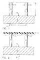
- FIG. 1is an elevational view in partial cross-section of a bottom mold provided at the initial step of a “self-molding” method of manufacturing an array of plastic microneedles, as constructed according to the principles of the present invention.
- FIG. 2is an elevational view in partial cross-section of the mold of FIG. 1 in a second step of the self-molding procedure.
- FIG. 3is an elevational view in partial cross-section of the mold of FIG. 1 in a third step of the self-molding procedure.
- FIG. 4is an elevational view in partial cross-section of the mold of FIG. 1 in a fourth step of the self-molding procedure.
- FIG. 5is an elevational view in partial cross-section of the mold of FIG. 1 in a fifth step of the self-molding procedure.
- FIG. 6is an elevational view in cross-section of an array of hollow microneedles constructed according to the self-molding procedure depicted in FIGS. 1-5.
- FIG. 7is a cross-sectional view of a top mold-half used in a micromolding procedure, according to the principles of the present invention.
- FIG. 8is an elevational view of the bottom half of the mold that mates to the top mold-half of FIG. 7, and which is used to form plastic microneedles according to the micromolding procedure.
- FIG. 9is an elevational view in partial cross-section of one of the method steps in the micromolding procedure using the mold halves of FIGS. 7 and 8.
- FIG. 10is an elevational view in partial cross-section of the mold of FIG. 9 depicting the next step in the micromolding procedure.
- FIG. 11is a cross-sectional view of an array of plastic microneedles constructed according to the micromolding procedure depicted in FIGS. 7-10.
- FIG. 12is an elevational view in partial cross-section of a top mold-half and a bottom planar surface used in creating an array of molded, plastic microneedles by a microembossing procedure, as constructed according to the principles of the present invention.
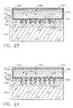
- FIG. 13is an elevational view in partial cross-section of the mold of FIG. 12 in a subsequent process step of the microembossing method.
- FIG. 14is an elevational view in partial cross-section of the mold if FIG. 12 showing a later step in the microembossing procedure.
- FIG. 15is a cross-sectional view of a microneedle array of hollow microneedles constructed by the mold of FIGS. 12-14.
- FIG. 15Ais a cross-sectional view of an array of microneedles which are not hollow, and are constructed according to the mold of FIGS. 12-14 without the micropillars.
- FIG. 16is an elevational view in partial cross-section of a two-piece mold used in a microinjection method of manufacturing plastic microneedles, as constructed according to the principles of the present invention.
- FIG. 17is a cross-sectional view of a microneedle array of hollow microneedles constructed by the mold of FIG. 16 .
- FIG. 18is a cross-sectional view of the initial semiconductor wafer that will be formed into an array of microneedles by a microfabrication procedure, according to the principles of the present invention.
- FIG. 19is a cross-sectional view of the semiconductor wafer of FIG. 18 after a hole pattern has been established, and after a silicon nitride layer has been deposited.
- FIG. 20is a cross-sectional view of the wafer of FIG. 18 after a photoresist mask operation, a deep reactive ion etch operation, and an oxidize operation have been performed.
- FIG. 21is a cross-sectional view of the wafer of FIG. 20 after the silicon nitride has been removed, and after a deep reactive ion etch has created through holes, thereby resulting in a hollow microneedle.
- FIG. 22is a perspective view of a microneedle array on a semiconductor substrate, including a magnified view of individual cylindrical microneedles.
- FIG. 23is a cross-sectional view of an iontophoretically enhanced body-fluid sensor, based upon a hollow microneedle array, as constructed according to the principles of the present invention.
- FIG. 24is a cross-sectional view of an iontophoretically enhanced body-fluid sensor, based upon a solid microneedle array, as constructed according to the principles of the present invention.
- FIG. 25is a cross-sectional view of an electrode, based upon a hollow microneedle array, as constructed according to the principles of the present invention.
- FIG. 26is a cross-sectional view of an electrode, based upon a solid microneedle array, as constructed according to the principles of the present invention.
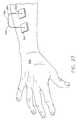
- FIG. 27is a perspective view of a sensing system attached to a human hand and forearm, which includes an iontophoretically enhanced body-fluid sensor as per FIG. 23 and an electrode as per FIG. 25 .
- FIG. 28is a cross-sectional view of an iontophoretically enhanced drug delivery system, based upon a hollow microneedle array, as constructed according to the principles of the present invention.
- FIG. 29is a cross-sectional view of an iontophoretically enhanced drug delivery system, based upon a solid microneedle array, as constructed according to the principles of the present invention.
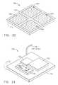
- FIG. 30is a perspective view of a closed-loop drug-delivery system, as viewed from the side of a patch that makes contact with the skin, as constructed according to the principles of the present invention.
- FIG. 31is a perspective view of the closed-loop drug-delivery system of FIG. 30, as seen from the opposite side of the patch.
- FIG. 1shows a mold generally designated by the reference numeral 10 that comprises a plurality of micropillars, including micropillars 12 and 14 , that are mounted to a base 16 having a planar upper surface 18 .
- Micropillar 12preferably is cylindrical in shape, and has an outer diameter designated “D 1 ,” whereas micropillar 14 (which also preferably is cylindrical in shape) has a diameter designated “D 2 .”
- the centerlines of micropillars 12 and 14are separated by a distance “D 3 ,” and the vertical height of micropillars 12 and 14 is designated by the letter “L 1 .”
- Microelectrode-discharge machiningcan be used to fabricate the mold 10 from metals, such as stainless steel, aluminum, copper, iron, tungsten, or other metal alloys. Mold 10 could also be fabricated from silicon or silicon carbide using integrated circuit processing, or photolithographic processing.
- FIG. 2depicts the mold 10 and a thin layer of plastic, such as a polymer film, designated by the reference numeral 20 , which is placed on the micropillars 12 and 14 , thereby making contact at the reference numerals 22 and 24 , respectively.
- a polymer filmdesignated by the reference numeral 20
- the polymeris heated to just above the melting temperature of the plastic material.
- Micropillars 12 and 14are also heated to a certain extent, but are held just below the melting temperature of the plastic material. This establishes a temperature gradient within the plastic film, after which the plastic film is subjected to natural gravitational forces, or placed in a centrifuge.
- an air-pressure gradientalso can be established across the deforming plastic film, by applying pressure from above, or by applying a vacuum from below the film level.
- the overall effect on the plastic filmis that it will undergo a “self-molding” operation, by way of the gravitational force or centrifugal force, and the air-pressure gradient can be used to accelerate the self-molding process.
- FIG. 3depicts the mold 10 at a further step in the processing of the plastic film, showing the result of the temperature gradient.
- This resultis that the areas contacting the micropillars (at the reference numerals 22 and 24 ) will have a smaller deformation as compared to the remaining portions of the plastic film 20 that are between the pillars 12 and 14 . Therefore, the portions 30 , 32 , and 34 of the plastic material will undergo greater deformation, as viewed on FIG. 3 .
- FIG. 4depicts the mold 10 at yet a later step in the self-molding process, showing the initial stage in which the mold (including micropillars 12 and 14 ) is heated above the melting temperature of the plastic material 20 .
- the plastic materialwill continue to melt and to be removed from the tops of the pillars 12 and 14 .
- the remaining portions not in contact with micropillars 12 and 14will continue to deform downward (as viewed on FIG. 4) at the reference numerals 30 , 32 , and 34 .
- FIG. 5depicts the mold 10 at the final stage of self-molding, which illustrates the fact that the plastic material has completely melted down and away from the tops 22 and 24 of the micropillars 12 and 14 .
- the mold and the plastic materialare both cooled down, thereby forming the final shape that will become the microneedles.
- This final shapeincludes an outer wall 40 and 42 for the microneedle being formed by micropillar 12 , and an outer wall at 44 and 46 for the microneedle being formed at the micropillar 14 .
- FIG. 6illustrates the cross-sectional shape of the microneedle array, generally designated by the reference numeral 60 , after it has been detached from the mold 10 .
- the left hand microneedle 62has a relatively sharp upper edge, which appears as points 50 and 52 .
- Its outer wallis illustrated at 40 and 42 , which are sloped with respect to the vertical, as designated by the angles “A 1 ” and “A 2 .”
- the right-hand side microneedle 64exhibits a similar sharp top edge, as indicated by the points 54 and 56 , and also exhibits a sloped outer wall at 44 and 46 .
- the angle of this outer wallis indicated at the angles “A 3 ” and “A 4 .”
- the preferred value of angles A 1 -A 4is in the range of zero (0) to forty-five (45) degrees.
- the inner diameter of the left-hand microneedle 62is indicated by the distance “D 1 ,” and the inner diameter of the right-hand microneedle 64 is indicated by the distance “D 2 .”
- These distances D 1 and D 2are substantially the same distance as the diameter of micropillars 12 and 14 , as indicated in FIG. 1 .
- the distance D 3 between the centerlines of the microneedles on FIG. 6is essentially the same as the distance D 3 between the micropillars on FIG. 1 .
- the length “L 2 ” of the microneedles on FIG. 6is somewhat less than the length L 1 on FIG. 1, although this length L 2 could theoretically be a maximum distance of L 1 .
- the plastic materialmay consist of any type of permanently deformable material that is capable of undergoing a gradual deformation as its melting point is reached or slightly exceeded.
- This “plastic material”could even be some type of metallic substance in a situation where the metallic material would deform at a low enough temperature so as to not harm the mold itself.
- the preferred materialis a polyamide such as nylon, although many other types of polymer material certainly could be used to advantage.
- Other potential materialsinclude: polyesters, vinyl, polysterene, polycarbonate, and acrylonitrilebutadisterene (ABS).
- ABSacrylonitrilebutadisterene
- FIG. 7depicts a top mold-half, generally designated by the reference numeral 110 , of a second embodiment of the present invention in which the manufacturing method for creating an array of hollow microneedles is performed by a micromolding procedure.
- the top mold-half 110includes two “microholes” that have sloped side walls, designated by the reference numerals 112 and 114 for the left-hand microhole 113 , and by the reference numerals 116 and 118 for the right-hand microhole 117 .
- the microholes 113 and 117have a vertical (in FIG. 7) dimension referred to herein as a distance “L 11 ”.
- Microholes 113 and 117correspond to a pair of micropillars 122 and 124 that are part of a bottom mold-half, generally designated by the reference number 120 , and illustrated in FIG. 8 .
- the sloped side walls of the microhole 113are depicted by the angles “A 11 ” and “A 12 ,” with respect to the vertical.
- the side walls of microhole 117are also sloped with respect to the vertical, as illustrated by the angles “A 13 ” and “A 14 ” on FIG. 7 .
- microhole 113preferably is in a conical overall shape, the angle A 11 will be equal to the angle A 12 ; similarly for microhole 117 , the angle A 13 will be equal to the angle A 14 . It is preferred that all microholes in the top mold-half 110 exhibit the same angle with respect to the vertical, which means that angles A 11 and A 13 are also equal to one another.
- angles A 11 -A 14is in the range of zero (0) through forty-five (45) degrees. The larger the angle from the vertical, the greater the trauma to the skin tissue when a microneedle is pressed against the skin. On FIG. 7, the illustrated angle A 11 is approximately twelve (12) degrees.
- the bottom mold-half 120includes a base 126 having a substantially planar top surface 128 , upon which the two micropillars 122 and 124 are mounted.
- These micropillarsare preferably cylindrical in shape, and have a diameter of D 11 and D 12 , respectively.
- the distance between the centerlines of these micropillarsis designated as D 13 .
- Diameters D 11 and D 12preferably are in the range 1-49 microns, more preferably about 10 microns.
- the distance “D 13 ”represents the separation distance between the center lines of micropillars 122 and 124 , which preferably is in the range 50-1000 microns, more preferably about 200 microns.
- the two mold-halves 110 and 120can be fabricated from metals using microelectrode-discharge machining techniques. Alternatively, the molds could be fabricated from silicon or silicon carbide using integrated circuit processing or lithographic processing.
- a thin plastic filmis placed on top of the micropillars and heated above the glass transition temperature of the plastic material while the plastic material 130 rests upon the tops of the pillars at 132 and 134 , thereby causing the plastic material to become sufficient pliable or “soft” for purposes of permanently deforming the material's shape.
- the temperature of the plastic materialwill not be raised above its melting temperature, although it would not inhibit the method of the present invention for the plastic material to become molten just before the next step of the procedure.
- the top mold-half 110is pressed downward and begins to deform the plastic film 130 .
- the two mold halves 110 and 120are aligned so that the microholes 113 and 117 correspond axially to the micropillars 122 and 124 , respectively.
- the two mold halvesnow begin to operate as a single mold assembly, generally designated by the reference numeral 100 .
- the two mold halves 110 and 120have completely closed, thereby squeezing all of the plastic material 130 away from the tops of the micropillars 122 and 124 .
- the plastic microneedlesare formed, and the mold and the plastic material are both cooled down.
- the wall 112 and 114 of the first microhole 113causes a side outer wall to be formed out of the plastic material at 150 and 152 .
- the corresponding inner wall of the microneedle 182is depicted at 160 and 162 , which is caused by the shape of the micropillar 122 . Since the outer wall is sloped, it will converge with the inner wall 160 and 162 , near the top points at 170 and 172 .
- a similar outer wall 154 and 156is formed by the inner wall 116 and 118 of microhole 117 .
- the inner wall of the microneedle 184is depicted at 164 and 166 , and these inner and outer walls converge near points 174 and 176 .
- FIG. 11illustrates the microneedle array, generally designated by the reference numeral 180 , after the mold is removed from the plastic material 130 .
- a lower relatively planar baseremains, as illustrated at 140 , 142 , and 144 .
- two different microneedlesare formed at 182 and 184 .
- the angles formed by the wallsare as follows: angle A 11 by walls 150 and 160 , angle A 12 by walls 162 and 152 , angle A 13 by walls 154 and 164 , and angle A 14 by walls 166 and 156 .
- the points at the top if the microneedles(designated at 170 , 172 , 174 , and 176 ) are fairly sharp, and this sharpness can be adjusted by the shape of the mold with respect to the microholes and micropillar orientations.
- microneedle 182The inner diameter of microneedle 182 is designated by the distance D 11
- the inner diameter of the microneedle 184is designated by the distance D 12
- the distance between the centerlines of these microneedlesis designated as D 13 . These distances correspond to those illustrated on FIG. 8 .
- angles A 11 -A 14are equal to one another, and that the angles fall within the range of zero (0) to forty-five (45) degrees.
- the preferred anglereally depends upon the strength of the material being used to construct the microneedles, in which a greater angle (e.g., angle A 11 ) provides greater strength. However, this angular increase also causes greater trauma to the skin.
- Microneedle array 180also includes a relatively flat base structure, as indicated at the reference numerals 140 , 142 , and 144 .
- This base structurehas a vertical thickness as designated by the dimension L 15 (see FIG. 11 ).
- the microneedle heightis designated by the dimension L 12 on FIG. 11 .
- the heightmust be sufficient to penetrate the skin through the stratum corneum and into the epidermis, and a preferred dimension for height L 12 is in the range of 50-200 microns (although, certainly microneedles shorter than 50 microns in length could be constructed in this manner—for use with skin cosmetics, for example).
- the thickness L 15can be of any size, however, the important criterion is that it be thick enough to be mechanically sound so as to retain the microneedle structure as it is used to penetrate the skin.
- a top mold-half 210is combined with a planar bottom mold-half 240 to create an entire mold, generally designated by the reference numeral 200 .
- the top mold-half 210contains an array of microholes with micropillars at the center of each of the microholes.
- a microhole 213having its conical wall at 212 and 214 , is preferably concentric with a micropillar 222
- a microhole 217having its conical wall at 216 and 218 , is preferably concentric with a micropillar 224 .
- microembossingThe fabrication method used in conjunction with the mold 200 is referred to herein as “microembossing” for the reason that the bottom mold-half 240 is simply a flat or planar surface. This greatly simplifies the construction of this particular mold.
- a thin plastic film at 230is placed upon the top surface 242 of this bottom mold-half 240 . In the later steps, it will be seen that the plastic material 230 is heated while the top mold-half 210 is pressed down against the bottom mold-half 240 .
- Microhole 213 and micropillar 222have an angular relationship as illustrated by the angles “A 21 ” and “A 22 .”
- These angles A 21 -A 24will preferably be in the range of zero (0) to forty-five (45) degrees from the vertical.
- the greater the anglethe greater the transport rate, however, also the greater trauma to the skin tissue when used.
- Micropillar 222preferably has a cylindrical shape with an outer diameter designated at “D 21 ,” and micropillar 224 similarly has a preferred cylindrical shape having a diameter “D 22 .”
- Diameters D 21 and D 22preferably are in the range 1-49 microns, more preferably about 10 microns.
- the distance “D23”represents the separation distance between the center lines of micropillars 222 and 224 , which preferably is in the range 50-1000 microns, more preferably about 200 microns.
- the length of the micropillars from the bottom surface 228 of the top mold-half 210 to the closed end of the microholes at 215 and 225 , respectively,is designated as the length “L 21 .”
- the micropillars 222 and 224are somewhat longer than this length L 21 , since they are to mate against the upper surface 242 of the bottom mold-half 240 , and therefore are longer by a distance designated as “L 25 .” In this manner, the microneedles will be hollow throughout their entire length.
- the combined length of dimensions L 21 and L 25preferably will be approximately 150 microns.
- the molds 210 and 240will preferably be made from a metal, in which microelectrode-discharge machining can be used to fabricate such metallic molds.
- the moldscould be fabricated from silicon or silicon carbide, for example, using integrated circuit processing or lithographic processing.
- the temperature of the plastic materialwill not be raised above its melting temperature, although it would not inhibit the method of the present invention for the plastic material to become molten just before the top mold 210 begins to be pressed down against the plastic material 230 .
- This top mold movementbegins to deform that plastic material 230 such that it begins to fill the microholes, as illustrated at 232 and 234 (for microhole 213 ) and at 236 and 238 (for microhole 217 ).
- the top mold-half 210has now been completely closed against the bottom planar mold-half 240 , and the plastic material 230 has now completely filled the microholes, as illustrated at 232 , 234 , 236 , and 238 .
- the shape of the plastic materialnow has a conical outer wall at 250 and 252 , and a corresponding cylindrical inner wall at 260 and 262 , for the left-hand microneedle 282 on FIG. 14 .
- the plastic material shapehas an outer conical wall at 254 and 256 , as well as a cylindrical inner wall at 264 and 266 .
- the conical outer walls and the cylindrical inner wallsconverge at the top points 270 and 272 , and 274 and 276 .
- the bottom surface 228 of the top mold-half 210causes a base to be formed in the plastic material 230 at the locations indicated by the reference numerals 244 , 246 , and 248 .
- a microneedle array 280has been formed out of the plastic material 230 , which as viewed on FIG. 15 depicts two microneedles 282 and 284 .
- the left-hand microneedle 282comprises an outer conical wall as viewed at 250 and 252 , and a hollow interior cylindrical wall at 260 and 262 . These walls converge at the top points (as viewed on this Figure) at 270 and 272 , and the convergence angle is given as “A 21 ” and “A 22 .”
- the right-hand microneedle 284comprises an outer conical wall 254 and 256 and a hollow interior cylindrical wall 262 and 264 .
- Angles A 21 -A 24are preferably in the range of zero (0) to forty-five (45) degrees.
- Microneedle array 280also includes a relatively flat base structure, as indicated at the reference numerals 244 , 246 , and 248 .
- This base structurehas a vertical thickness as designated by the dimension L 25 .
- the microneedle heightis designated by the dimension L 22 . The height must be sufficient to penetrate the skin through the stratum corneum and into the epidermis, and has a preferred dimension in the range of 50-200 microns (although, as noted above, much shorter microneedles could be constructed in this manner).
- the thickness L 25can be of any size, however, the important criterion is that it be thick enough to be mechanically sound so as to retain the microneedle structure as it is used to penetrate the skin.
- the inside diameter of the hollow microneedlesis illustrated as D 21 and D 22 , which correspond to the diameters of a cylindrical hollow opening.
- the distance D 23represents the separation distance between the centerlines of the two microneedles 282 and 284 , in this array 280 .
- FIG. 15Arepresents an alternative embodiment in which a microneedle array 290 comprises “solid” microneedles 292 and 294 , rather than hollow microneedles as seen at 282 and 284 on FIG. 15 .
- These solid microneedles 292 and 294are formed by a similar mold as viewed on FIG. 12, but with the micropillars 222 and 224 removed from this mold, and a change in shape of the microholes 213 and 217 .
- This simple changeallows the solid microneedles to be formed within conical microholes (not shown on FIG. 12 ), and produces a pointed conical shape, as exhibited by the outer conical wall 250 and 252 for microneedle 292 , with a top pointed surface at 296 .
- microneedle 294has a conical outer wall 254 and 256 , with a similar top pointed surface at 298 .
- the other dimensions and features of the solid microneedle array 290can be exactly the same as those features of the hollow microneedle array 280 of FIG. 15, or the dimensions may be different since this is for a different application.
- the holes 251 , 253 , 255can be fabricated during the microstamping or micrembossing procedure via inclusion of appropriate micropillars located adjacent to the microholes 213 and 217 in FIG. 12 .
- a mold 300consists of two mold-halves 310 and 340 . These mold-halves 310 and 340 are virtually identical in shape, and probably in size, as compared to the mold-halves 210 and 240 of the mold 200 on FIG. 12 .
- the main difference in FIG. 16is that these mold-halves are to be used in a microinjection procedure in which molten plastic material is injected from the side at 330 into the opening between the mold-halves formed by the bottom surface 328 of the top mold-half 310 and the top surface 342 of the bottom mold-half 340 .
- the mold structure 300is preferably made of a metallic material by a micro-machining process, although it could be made of a semiconductor material such as silicon or silicon carbide, if desired.
- the plastic material 330is being filled from the left-hand side in this view, and has already filled a first microhole 313 with plastic material.
- the plastic materialis illustrated as it is advancing, and has reached the point at the reference numeral 336 .
- the plastic materialwill reach and fill the second microhole 317 , which has a conical inner wall at 316 and 318 , and a corresponding micropillar 324 .
- the plastic materialhas filled the shape around a micropillar 322 and within the conical walls of this microhole 313 , to form a hollow cone having an outer wall at 332 and 334 .
- the plastic materialwill be forced upward until it reaches a top point as seen at the reference numerals 370 and 372 .
- the outer conical shape at 332 and 334will converge with the interior shape of the micropillar 322 at an angle designated by the angles “A 31 ” and “A 32 .”
- Microhole 317also exhibits a converging angular shape at “A 33 ” and “A 34 ,” which is the convergence angle between the conical walls 316 and 318 and the outer cylindrical shape of the micropillar 324 .
- the separation between the surfaces 328 and 342is given by the length dimension “L 35 ,” which will become the thickness of the planar face material that will remain once the mold is opened.
- the vertical dimension (in FIG. 16) of the microholesis given by the dimension “L 31 ” which preferably will create microneedles long enough to penetrate through the stratum corneum and into the epidermis, but not so long as to penetrate all the way to the dermis.
- FIG. 17illustrates the microneedle array, generally designated by the reference numeral 380 .
- two microneedlesare illustrated at 382 and 384 .
- These microneedleshave a length “L 32 ,” which in theory should be exactly the same as the dimension L 31 on FIG. 16, assuming the mold was properly filled with material.
- a preferred distance for L 32is in the range of 50-200 microns.
- the plastic material 330has a planar base structure, as illustrated at 344 , 346 , and 348 . The thickness of this base structure is the dimension L 35 .
- the microneedlesthemselves exhibit a conical outer wall at 350 and 352 for the left-hand microneedle 382 , and at 354 and 356 for the right-hand microneedle at 384 .
- Each microneedlehas a hollow interior, as illustrated by the cylindrical surface 360 and 362 for microneedle 382 , and 364 and 366 for microneedle 384 . These surfaces converge to form points (as illustrated on FIG. 17) at 370 and 372 for microneedle 382 , and at 374 and 376 for microneedle 384 .
- the convergence angle of these wallsis designated by the angles A 31 -A 34 , and preferably will be in the range of zero (0) to forty-five (45) degrees.
- microneedle 382The inner diameter of microneedle 382 is given by the dimension D 31 , and for microneedle 384 is given by dimension D 32 . These dimensions preferably are in the range 1-49, more preferably about 10 microns.
- the separation distance between the center lines of the microneedlesis given at D 33 , which preferably is in the range 50-1000 microns, more preferably about 200 microns.
- the height L 32is preferably in the range of 50-200 microns and, depending upon the convergence angle A 31 -A 34 , the bottom width of the conical microneedles will vary depending upon the exact application for usage. In one preferred embodiment, this bottom dimension, designated by “D 34 ” and “D 35 ,” will be approximately twenty (20) microns.
- the vertical thickness at L 35will likely be made as thin as possible, however, the important criterion is that it is sufficiently thick to be mechanically sound to hold the microneedle array 380 together as a single structure during actual usage. It is likely that, for most plastic materials that might be used in this molding procedure, the dimension L 35 will be in the range of ten (10) microns through two (2) mm, or greater.
- plastic microneedlescould be utilized to create hollow microneedles in an array, without departing from the principles of the present invention. It will also be understood that various types of materials could be used for such molding procedures, including metallic materials that might be cast using higher temperature dies of a similar shape and size, without departing from the principles of the present invention.
- microneedlescould be utilized to construct an array of hollow microneedles, without departing from the principles of the present invention. It will be still further understood that the angular relationship between the microneedles and their planar base surface need not be precisely perpendicular (although that configuration is preferred), but could have some variation without departing from the principles of the present invention; the microneedles also need not be exactly parallel with one another, even though that configuration is preferred.
- microneedle shapescould be used than a cylindrical shape, if desired, without departing from the principles of the present invention.
- an array of solid microneedlescould be fabricated using the molding techniques described herein, without departing from the principles of the present invention.
- FIG. 18a procedure for forming dry etched microneedles will be described using an example of microfabrication (e.g., semiconductor fabrication) techniques.
- a single crystal silicon waferat reference numeral 400 , it is preferred to use a double side polish wafer and to grow an oxide layer on the entire outer surface.
- a cross-section of this waferappears as a substrate 410 , a top oxide layer 412 , and a bottom oxide layer 414 .
- Any single crystal silicon waferwill suffice, although it is preferred to use a crystal structure 100-type wafer, for reasons that will be explained below.
- a 110-type wafercould be used, however, it would create different angles at certain etching steps.
- the first stepis a pattern oxide step which is performed on the top side only to remove much of the top oxide layer 412 .
- the pattern usedwill create multiple annular regions comprising two concentric circles each, of which the cross-section will appear as the rectangles 416 and 418 on FIG. 19 .
- these annular-shaped featureswill have the appearance as illustrated on the perspective view of FIG. 22 at the reference numerals 416 and 418 .
- These annular oxide patternsare the initial stages of the array locations of the multiple microneedles that will be formed on this substrate 410 .
- the next stepis to deposit a layer of silicon nitride using a low pressure vapor deposition step, which will form a silicon nitride layer on both the top and bottom surfaces of the substrate 410 .
- the bottommost layer 422 and 424is one continuous layer at this step, although it is not illustrated as such on FIG. 19, since a later step etches out a portion of the bottom side of the substrate between the layers 422 and 424 .
- a pattern bottom procedurein which a square hole is patterned beneath the annulus 416 , 418 , which is not directly visible on FIG. 19 .
- the square holes placed by the pattern bottom procedureare now used in a KOH etching step that is applied to the bottom side only of the substrate 410 .
- This KOH etching stepcreates a window along the bottom of the substrate as viewed along the surfaces 432 , 430 , and 434 on FIG. 19 .
- This windowinterrupts the oxide layer 414 along the bottom of substrate 410 , and divides it (on FIG. 19) into two segments 413 and 415 .
- This window (or hole)also interrupts the silicon nitride layer into two segments (on FIG. 19) 422 and 424 .
- the slope angle of the etched window along surfaces 432 and 434is 54.7 degrees, due to the preferred 100-type silicon material. If type-110 silicon material was used, then this slope would be 90 degrees. That would be fine, however, crystalline silicon 100-type material is less expensive than silicon 110-type material.
- the next fabrication operationis to perform a pattern top nitride procedure using a photoresist mask. This removes the entire upper silicon nitride layer 420 except where the photoresist mask was located, which happens to be aligned with the upper oxide annulus at 416 and 418 .
- the remaining upper silicon nitrideis indicated at the reference numeral 426 on FIG. 20, although at this stage in the fabrication procedure, the upper surface will still be a planar surface at the level of the oxide layer 416 and 418 , across the entire horizontal dimension of FIG. 20 .
- the next fabrication stepis to perform a deep reactive ion etch (DRIE) operation on the top surface of the substrate 410 , which will etch away a relatively deep portion of the upper substrate except at locations where the silicon nitride layer still remains, i.e., at 426 .
- DRIEdeep reactive ion etch
- the next fabrication stepis to oxidize all of the bare silicon that is now exposed along the outer surfaces. This will form a layer of silicon dioxide at locations on FIG. 20, such as at 440 , 442 , 444 , 446 , 452 , 450 , and 454 .
- the outer silicon nitride layers at 426 , 423 , and 425are not oxidized.
- the outer silicon nitride layers 423 and 425are essentially the same structures as layers 422 and 424 on FIG. 19, although the silicon dioxide layers 452 and 454 are now formed above these “pads” 423 and 425 .
- this oxidationbe a minimal amount, just enough for a future DRIE masking procedure, and that the oxidized thickness be approximately 5,000 Angstroms.
- the silicon waferhas the appearance of that depicted in FIG. 20 .
- the next step in the fabrication procedureis to remove the silicon nitride layer on the top, which will remove the layer at 426 as seen on FIG. 20 . This will expose a circular region in the very center of the annulus such that pure silicon is now the outermost material on the top side of the wafer. After that has occurred, a deep reactive ion etch operation is performed to create a through-hole at the reference numeral 460 on FIG. 21 . After this step has been performed, there will be pure silicon exposed as the inner wall of the through-hole 460 . Therefore, the next step is to oxidize the entire wafer, which will place a thin cylindrical shell of silicon dioxide around the inner diameter of through-hole 460 , and this oxidized layer is viewed on FIG. 21 at 462 and 464 .
- a microneedle 465is the result, having an outer diameter at “D 41 ,” and an inner diameter through-hole at “D 42 .” It is preferred that the inner diameter D 42 have a distance in the range of 5-10 microns.
- the height of the microneedleis given at the dimension “L 41 ,” which has a preferred dimension in the range of 50-200 microns.
- the substrate 410has been divided into halves at 410 A and 410 B.
- the bottom oxide layer 450has been divided in halves at 450 A and 450 B.
- This chamber 470can be used to store a fluid, such as insulin, that is to be dispensed through the cylindrical opening 460 in the hollow microneedle 465 .
- this chamberis not very large in overall physical volume, and it normally would be preferred to interconnect all of such chambers for each of the microneedles in the overall array so that a common fluid source could be used to dispense fluid to each of these chambers 470 .
- microneedlesthere may be a need to dispense a physically much larger volume of fluid, and it also may be desirable to provide a pressure source, such as a pump. In such situations, it may be preferable to have an external storage tank that is in communication with each of the fluid chambers 470 on the wafer that is used to make up the array of microneedles, such as microneedle 465 .
- FIG. 22depicts an array of microneedles on substrate 410 , and also illustrates a magnified view of some of these microneedles 465 .
- Each microneedle 465exhibits a cylindrical shape in the vertical direction, and has an outer diameter D 41 , an annular shaped upper surface at 416 and 418 , and a through-hole at 460 .
- Each of the microneedles 465extends out from the planar surface 440 of the substrate 410 .
- substrate 410can either be made much larger in height so as to have a very large internal volume for holding a fluid substance, or the substrate itself could be mounted onto a different material that has some type of fluidic opening that is in communication with the chambers 470 of the individual microneedles 465 .
- microneedle shapescould be used than a cylindrical shape with an annular top surface, and in fact, the top surface of such microneedles could be sloped to create a sharper edge, if desired, without departing from the principles of the present invention.
- microneedle length or diameterthat is appropriate for a particular chemical fluidic compound and for a particular skin structure could be used without departing from the principles of the present invention.
- the microneedlepenetrate through the stratum corneum into the epidermis, but not penetrate into the dermis itself. This means that such microneedles would typically be no longer than two hundred (200) microns, though they must typically be at least fifty (50) microns in length. Of course, if cosmetic applications were desired, then the microneedle could be much shorter in length, even as short as one (1) micron.
- fluid-holding chamberany size or shape of fluid-holding chamber could be used in a drug-delivery system, which will be further discussed hereinbelow.
- a fluid-holding chamberwould also preferably be in communication with the through-holes 460 of each of the microneedles 465 .
- FIG. 23depicts an iontophoretically enhanced body-fluid sensor that is based upon a hollow microneedle array, generally designated by the reference numeral 500 .
- Sensor 500includes a plurality of microneedles 530 , which are each hollow, having a vertical opening throughout, as indicated at 532 .
- a fluid chamber 510is in communication with the hollow portions 532 of the array of microneedles 530 .
- Fluid chamber 510is constructed of a bottom (in FIG. 23) planar surface 512 —which has openings that are aligned with the microneedles 530 —a left vertical wall 514 , and a right vertical wall 516 .
- the top (or ceiling) of the fluid chamber 510is made up of a planar material which is divided into individual electrodes.
- the middle electrode 525is part of the fluid sensor, and makes it possible to measure a current or voltage within the fluid chamber 510 .
- Electrodes 520 and 522are electrically connected to one another (and can be of a single structure, such as an annular ring) so as to act as the iontophoretic electrodes (i.e., as either an anode or a cathode) that facilitate the transport of fluid through the hollow microneedles 530 from the skin into the fluid chamber 510 .
- the height of the fluid chamber structureis designated as “L 50 ,” which could be any reasonable dimension that is large enough to hold a sufficient volume of fluid for a particular application.
- the fluid chamber 510could be connected to a much larger external reservoir (not shown), and a pump could even be used if pressure or vacuum is desired for a particular application.
- the layer 540represents the stratum corneum
- the layer 542represents the viable epidermis
- the largest layer 544represents the dermis, which contains nerves and capillaries.
- microneedles 530into the stratum corneum 540 and epidermis 542 decreases the electrical resistance of the stratum corneum by a factor of approximately fifty (50).
- the applied voltagetherefore, during iontophoresis can be greatly reduced, thereby resulting in low power consumption and improved safety.
- Iontophoresisprovides the necessary means for molecules to travel through the thicker dermis into or from the body.
- the combination of the microneedles and the electric field that is applied between the electrodes 520 and 522 (acting as an anode, for example) and a remotely placed electrode (e.g., electrode assembly 505 , viewed on FIG. 25, and acting as a cathode, for example)provides for an increase in permeability for both the stratum corneum and the deeper layers of skin.
- the iontophoresisprovides higher transport rates in the epidermis and dermis. This is not only true for small sized molecules, but also for the larger and more complex useful molecules.
- the body-fluid sampling sensor 500can be used for a continuous non-invasive measurement of blood glucose level, for example.
- Glucoseis extracted through the skin by reverse iontophoresis, and its concentration is then characterized by a bioelectrochemical sensor.
- the sensorcomprises the chamber 510 that is filled with hydrogel and glucose oxidase, and the electrode 525 .
- the glucose moleculesare moved from the body by the flow of sodium and chloride ions caused by the applied electric potential.
- the detection of the glucose concentration in the hydrogel padis performed by the bioelectrochemical sensor.
- FIG. 24An alternative embodiment 550 is depicted in FIG. 24, in which the microneedles 580 are solid, rather than hollow.
- a fluid-filled chamber 560is provided and also comprises hydrogel filled with glucose oxidase.
- the chamber 560is made of a bottom wall 562 that has openings proximal to the individual microneedles 580 , in which these openings are designated by the reference numeral 585 .
- Chamber 560also includes side walls 564 and 566 , as well as electrodes 570 , 572 ,and 575 .
- the electrode 575is constructed as part of the bioelectrochemical sensor.
- the electrodes 570 and 572act as the iontophoretic electrodes, acting either as an anode or cathode to set up an electric current through the skin which flows to a remotely-attached (to the skin) electrode (e.g., electrode assembly 555 , viewed on FIG. 26 ).
- the transport rate of fluidsis enhanced by not only the piercing effect of the microneedles 580 , but also the electric field inducing a current through the skin.
- glucoseis attracted into the chamber 560 , and its concentration is measured by the bioelectrochemical sensor.
- the height of the fluid chamber structureis designated as “L 55 ,” which could be any reasonable dimension that is large enough to hold a sufficient volume of fluid for a particular application.
- the fluid chamber 560could be connected to a much larger external reservoir (not shown), and a pump could even be used if pressure or vacuum is desired for a particular application.
- FIG. 25depicts an iontophoretic electrode assembly that is based upon a hollow microneedle array, generally designated by the reference numeral 505 .
- Electrode assembly 505includes a plurality of microneedles 531 , each being hollow and having a vertical opening throughout, as indicated at 533 .
- a fluid chamber 511is in communication with the hollow portions 533 of the array of microneedles 531 .
- Fluid chamber 511is constructed of a bottom planar surface 513 —which has openings that are aligned with the microneedles 531 —a left vertical wall 515 , and a right vertical wall 517 .
- the top (or ceiling) of fluid chamber 511is made of a planar electrode material 526 .
- the electrode 526is to be electrically connected to a low-current voltage source (not shown on FIG. 25 ), either through a substrate pathway (such as a integrated circuit trace or a printed circuit foil path) or a wire (also not shown on FIG. 25 ).
- the height of the fluid chamber 511is given by the dimension “L 52 ,” which can be of any practical size to hold a sufficient amount of hydrogel, for example, to aid in the conduction of current while acting as the electrode.
- the fluid within chamber 511preferably would not be electrically charged.
- the hollow microneedles 531penetrate the stratum corneum 540 and into the viable epidermis 542 .
- the microneedles 531preferably will not be sufficiently long to penetrate all the way to the dermis 544 .
- FIG. 26An alternative embodiment 555 is depicted in FIG. 26, in which the microneedles 581 are solid, rather than hollow.
- a fluid chamber 561is provided and preferably is filled with hydrogel (which is not electrically charged).
- Chamber 561is made of a bottom wall 563 that has openings proximal to the individual microneedles 581 , in which these openings are designated by the reference numeral 586 .
- Chamber 561also includes side walls 565 and 567 , as well as a top (or ceiling) electrode 576 .
- the electrode 576may act as a cathode, for example, in a situation where electrode assembly 555 is being used in conjunction with a body-fluid sensor, such as sensor assembly 550 viewed on FIG.
- the height “L 57 ” of fluid chamber 561could be any reasonable dimension that is large enough to hold a sufficient volume of the hydrogel to enhance the fluid flow via the electric field between the respective anode and cathode of the system.
- FIG. 27illustrates a portion of a human arm and hand 590 , along with a drug delivery electrode assembly 500 and a second electrode assembly 505 . Both electrodes are attached to the skin of the human user, via their microneedles, such as the hollow microneedles 530 (viewed on FIG. 23) and the hollow microneedles 531 (viewed on FIG. 25 ).
- a low current power supplygenerally designated by the reference numeral 596 , that is connected to each of the electrodes via a wire 592 or a wire 594 , respectively.
- any type of physical electrical circuitcould be used to provide the electrical conductors and power supply necessary to set up an appropriate electrical potential, without departing from the principles of the present invention.
- the electrode assemblies and wiring, along with an associated power supplycould all be contained on a single apparatus within a substrate, such as that viewed on FIGS. 30 and 31 herein, or by use of printed circuit boards.
- FIG. 28depicts an iontophoretically enhanced fluidic drug delivery apparatus that is based upon a hollow microneedle array, generally designated by the reference numeral 600 .
- Drug-delivery apparatus 600includes a plurality of microneedles 630 , which are each hollow, having a vertical opening throughout, as indicated at 632 .
- a fluid chamber 610is in communication with the hollow portions 632 of the array of microneedles 630 .
- Fluid chamber 610is constructed of a bottom (in FIG. 28) planar surface 612 —which has openings that are aligned with the microneedles 630 —a left vertical wall 614 , and a right vertical wall 616 .
- the top (or ceiling) of the fluid chamber 610is made up of a planar material 620 that acts as an electrode. Electrode 620 is part of the drug delivery apparatus, and makes it possible to induce a current flow through fluid chamber 610 . Electrodes 620 and 622 are connected so as to act as the iontophoretic electrodes (i.e., as either an anode or a cathode) that facilitate the transport of fluid through the hollow microneedles 630 from the fluid chamber 610 into the skin.
- the iontophoretic electrodesi.e., as either an anode or a cathode
- the height of the fluid chamber structureis designated as “L 60 ,” which could be any reasonable dimension that is large enough to hold a sufficient volume of fluid for a particular drug delivery application.
- the fluid chamber 510could be connected to a much larger external reservoir (not shown), and a pump could even be used if pressure or vacuum is desired for a particular application.
- the layer 540represents the stratum corneum
- the layer 542represents the viable epidermis
- the largest layer 544represents the dermis, which contains nerves and capillaries.
- microneedles 630 into the stratum corneum 540 and epidermis 542decreases the electrical resistance of the stratum corneum by a factor of approximately fifty (50).
- the applied voltagetherefore, during iontophoresis can be greatly reduced, thereby resulting in low power consumption and improved safety. Iontophoresis provides the necessary means for molecules to travel through the thicker dermis into or from the body.
- the combination of the microneedles and the electric field that is applied between the electrodes 620 and 622 (acting as anodes, for example), and another electrode (e.g., electrode assembly 505 , acting as a cathode) that is attached elsewhere on the skin of the user,provides for an increase in permeability for both the stratum corneum and the deeper layers of skin. While the transport improvement in stratum corneum is mostly due to microneedle piercing, the iontophoresis provides higher transport rates in the epidermis and dermis. This is not only true for small sized molecules, but also for the larger and more complex useful molecules.
- the drug delivery apparatus 600can be used for a continuous non-invasive medical device that can continuously deliver a fluidic drug through the skin and into the body.
- a fluidic drugfor example, insulin could be delivered to the blood stream via the microneedles 531 , through the stratum corneum 540 and epidermis 542 , and also into the dermis 544 where the insulin would be absorbed into the capillaries (not shown).
- FIG. 29An alternative embodiment 650 is depicted in FIG. 29, in which the microneedles 680 are solid, rather than hollow.
- a fluid-filled chamber 660is provided and also contains hydrogel.
- Chamber 660is made of a bottom wall 662 that has openings proximal to the individual microneedles 680 , in which these openings are designated by the reference numeral 685 .
- Chamber 660also includes side walls 664 and 666 , as well as electrodes 670 , 672 , and 675 .
- the electrode 675is constructed as part of the bioelectrochemical sensor.
- the electrodes 670 and 672act as the iontophoretic electrodes, acting either as the anode or cathode to set up an electric current through the skin, in conjunction with another electrode assembly (such as electrode assembly 655 , viewed on FIG. 26) placed elsewhere on the user's skin.
- the transport rate of fluidsis enhanced by not only the piercing effect of the microneedles 680 , but also the electric field inducing a current through the skin.
- insulinis repelled from the chamber 660 , and therefore, flows out through openings 685 proximal to microneedles 680 , then into the user's skin.
- the height of the fluid chamber structureis designated as “L 65 ,” which could be any reasonable dimension that is large enough to hold a sufficient volume of fluid for a particular application.
- the fluid chamber 660could be connected to a much larger external reservoir (not shown), and a pump could even be used if pressure or vacuum is desired for a particular application.
- FIG. 30depicts a closed-loop drug-delivery system generally designated by the reference numeral 700 .
- This closed-loop system 700includes a pair of iontophoretic pads, generally designated by the reference numerals 500 and 505 , which each include an array of microneedles for fluid sampling.
- Pad 500comprises a sensor assembly (as described hereinabove with respect to FIG. 23 ), and pad 505 comprises an electrode assembly (as described hereinabove with respect to FIG. 25 ).
- Closed-loop system 700also includes a pair of iontophoretic pads, generally designated by the reference numerals 600 and 605 , that each include an array of microneedles for drug delivery.
- Pad 600comprises a drug delivery apparatus (as described hereinabove with respect to FIG. 28 ), and pad 505 comprises an electrode assembly (as described hereinabove with respect to FIG. 25 ).
- iontophoretic pads having solid microneedlescould instead be used, such that pads 500 and 600 (with hollow microneedles) could be replaced by pads 550 and 650 (with solid microneedles), and pad 505 (with hollow microneedles) could be replaced by a pad 555 (with solid microneedles).
- Pads 500 and 600are mounted to a substrate 710 , which can be made of either a solid or a somewhat flexible material. Within substrate 710 preferably resides a reservoir 712 (within the substrate 710 ) that holds the fluid which is to be dispensed through the microneedles of pads 600 . Reservoir 712 could be made up of individual “small” chambers, such as a large number of chambers 610 that are connected to a source of fluidic drug.
- the reservoir 712preferably is completely contained within substrate 710 , and cannot be seen from this view of FIG. 31 .
- a fluid channel(such as a flexible at 730 ) could be connected into substrate 710 and, by use of a pump (not shown), further quantities of the fluid could be provided and dispensed through the microneedles of pads 600 , using fluidic pressure.
- FIG. 31illustrates the opposite side of the closed-loop system 700 .
- a controller 720is mounted to the upper surface (in this view) of substrate 710 .
- Controller 720preferably comprises a type of microchip that contains a central processing unit that can perform numeric calculations and logical operations.
- a microprocessorthat executes software instructions in a sequential (or in a parallel) manner would be sufficient.
- a microcontroller integrated circuitwould also suffice, or an ASIC that contains a microprocessor circuit.
- Adjacent to controller 720is an iontophoretic power supply with a battery, the combination being generally designated by the reference numeral 722 .
- a visual indicatorcan be placed on the surface of the substrate, as at 730 . This visual indicator could give a direct reading of the quantity of interest, such as glucose concentration, or some other body-fluid parameter.
- the visual indicatorpreferably comprises a liquid crystal display that is capable of displaying alphanumeric characters, including numbers.
- microneedlesWhile a pumping system that creates fluid pressure could be used for dispensing a fluidic drug into a body through hollow microneedles, such as emplaced on pads 600 , it is preferred to use an iontophoresis method to enhance the delivery of the drugs through the microneedles. As discussed hereinabove, application of microneedles can decrease the electrical resistance of the stratum corneum by a factor of fifty (50), and so the voltage necessary to facilitate iontophoresis can be greatly reduced, improving safety and requiring much less power consumption.
- 50the voltage necessary to facilitate iontophoresis
- the molecules making up the fluid drugwill travel through the thicker dermis into or from the body, and the combination of both transport-enhancing methods provides an increase in permeability for both the stratum corneum and the deeper layers of the skin.
- the transport improvement in the stratum corneumis mostly due to microneedle piercing, although the iontophoresis provides higher transport rates in the epidermis and dermis.
- the closed-loop drug-delivery system and fluid-sampling system 700can be used for continuous noninvasive measurement of blood glucose level by extracting, via reverse iontophoresis, glucose through the skin and measuring its concentration by the bioelectrochemical sensor (such as the sensor constructed of the hydrogel chamber 510 and sensor electrode 525 , along with the controller 720 ).
- the hydrogel pads containing microneedlesi.e., pads 500
- the proper amount of insulinfor example, can be dispensed through the other pair of pads 600 that make up part of the closed-loop system 700 .
- drug deliveryis performed by applying an electric potential between two microneedle array electrodes.
- One of the electrodesis filled with an ionized drug (such as insulin), and the charged drug molecules move into the body due to the electric potential.
- Controller 720will determine how much of a drug is to be dispensed through the microneedle array 600 at any particular time, thereby making the closed-loop system 700 a “smart” drug-delivery system.
- This smart drug-delivery systemcan be used as an artificial pancreas for diabetes patients, as a portable hormone-therapy device, as a portable system for continuous out-patient chemotherapy, as a site-specific analgesic patch, as a temporary and/or rate-controlled nicotine patch, or for many other types of drugs.
- Such systemscould be made as a disposable design, or as a refillable design.
- the closed-loop system 700can be used in many applications, including as a painless and convenient transdermal drug-delivery system for continuous and controlled outpatient therapies, a painless and convenient body-fluid sampling system for continuous and programmed outpatient body-fluid monitoring, as a high-rate transdermal drug delivery system, or as a high-accuracy transdermal body-fluid sampling system.
- the closed-loop system 700 of the present inventioncan be used as a portable high-accuracy painless sensor for outpatient blood glucose-level monitoring, as a portable system for continuous or rate controlled outpatient chemotherapy, as a temporary and rate controlled nicotine patch, as a site-specific controlled analgesic patch, as an externally attached artificial pancreas, as externally attached artificial endocrine glands, as temperature-controlled fever-reducing patches, as heart rate-controlled nitroglycerin high-rate transdermal patches, as temporarily controlled hormonal high-rate transdermal patches, as erectile dysfunction treatment high-rate transdermal patches, and as a continuous accurate blood-analysis system.
- Another use of the closed-loop system 700 of the present inventionis to form a portable drug delivery system for outpatient delivery of the following drugs and therapeutic agents, for example: central nervous system therapy agents, psychic energizing drugs, tranquilizers, anticonvulsants, muscle relaxants and anti-parkinson agents, smoking cessation agents, analgetics, antipyretics and anti-inflammatory agents, antispasmodics and antiulcer agents, antimicrobials, antimalarias, sympathomimetric patches, antiparasitic agents, neoplastic agents, nutritional agents, and vitamins.
- drugs and therapeutic agentsfor example: central nervous system therapy agents, psychic energizing drugs, tranquilizers, anticonvulsants, muscle relaxants and anti-parkinson agents, smoking cessation agents, analgetics, antipyretics and anti-inflammatory agents, antispasmodics and antiulcer agents, antimicrobials, antimalarias, sympathomimetric patches, antiparasitic agents, neoplastic agents, nutritional agents,
- the length of the individual microneedlesis by far the most important dimension with regard to providing a painless and bloodless drug-dispensing system, or a painless and bloodless body-fluids sampling system using the opposite direction of fluid flow. While the dimensions discussed hereinabove are preferred, and the ranges discussed are normal for human skin, it will further be understood that the microneedle arrays of the present invention can be used on skin of any other form of living (or even dead) creatures or organisms, and the preferred dimensions may be quite different as compared to those same dimensions for use with human skin, all without departing from the principles of the present invention.
Landscapes
- Engineering & Computer Science (AREA)
- Mechanical Engineering (AREA)
- Health & Medical Sciences (AREA)
- Manufacturing & Machinery (AREA)
- Life Sciences & Earth Sciences (AREA)
- Medical Informatics (AREA)
- Hematology (AREA)
- Microelectronics & Electronic Packaging (AREA)
- Chemical & Material Sciences (AREA)
- Dermatology (AREA)
- Forests & Forestry (AREA)
- Anesthesiology (AREA)
- Biomedical Technology (AREA)
- Heart & Thoracic Surgery (AREA)
- Analytical Chemistry (AREA)
- Animal Behavior & Ethology (AREA)
- General Health & Medical Sciences (AREA)
- Public Health (AREA)
- Veterinary Medicine (AREA)
- Media Introduction/Drainage Providing Device (AREA)
- Measurement Of The Respiration, Hearing Ability, Form, And Blood Characteristics Of Living Organisms (AREA)
- Measuring And Recording Apparatus For Diagnosis (AREA)
- Acyclic And Carbocyclic Compounds In Medicinal Compositions (AREA)
Abstract
Description
Claims (3)
Priority Applications (1)
| Application Number | Priority Date | Filing Date | Title |
|---|---|---|---|
| US09/956,520US6471903B2 (en) | 1999-06-09 | 2001-09-19 | Method for manufacturing an intracutaneous microneedle array |
Applications Claiming Priority (2)
| Application Number | Priority Date | Filing Date | Title |
|---|---|---|---|
| US09/328,946US6312612B1 (en) | 1999-06-09 | 1999-06-09 | Apparatus and method for manufacturing an intracutaneous microneedle array |
| US09/956,520US6471903B2 (en) | 1999-06-09 | 2001-09-19 | Method for manufacturing an intracutaneous microneedle array |
Related Parent Applications (1)
| Application Number | Title | Priority Date | Filing Date |
|---|---|---|---|
| US09/328,946DivisionUS6312612B1 (en) | 1999-06-09 | 1999-06-09 | Apparatus and method for manufacturing an intracutaneous microneedle array |
Publications (2)
| Publication Number | Publication Date |
|---|---|
| US20020020688A1 US20020020688A1 (en) | 2002-02-21 |
| US6471903B2true US6471903B2 (en) | 2002-10-29 |
Family
ID=23283160
Family Applications (3)
| Application Number | Title | Priority Date | Filing Date |
|---|---|---|---|
| US09/328,946Expired - LifetimeUS6312612B1 (en) | 1999-06-09 | 1999-06-09 | Apparatus and method for manufacturing an intracutaneous microneedle array |
| US09/579,798Expired - LifetimeUS6451240B1 (en) | 1999-06-09 | 2000-05-26 | Method of manufacturing an intracutaneous microneedle array |
| US09/956,520Expired - LifetimeUS6471903B2 (en) | 1999-06-09 | 2001-09-19 | Method for manufacturing an intracutaneous microneedle array |
Family Applications Before (2)
| Application Number | Title | Priority Date | Filing Date |
|---|---|---|---|
| US09/328,946Expired - LifetimeUS6312612B1 (en) | 1999-06-09 | 1999-06-09 | Apparatus and method for manufacturing an intracutaneous microneedle array |
| US09/579,798Expired - LifetimeUS6451240B1 (en) | 1999-06-09 | 2000-05-26 | Method of manufacturing an intracutaneous microneedle array |
Country Status (7)
| Country | Link |
|---|---|
| US (3) | US6312612B1 (en) |
| EP (1) | EP1183064B1 (en) |
| JP (1) | JP4436992B2 (en) |
| AU (1) | AU5727900A (en) |
| CA (2) | CA2376283C (en) |
| TW (1) | TW512067B (en) |
| WO (1) | WO2000074764A1 (en) |
Cited By (174)
| Publication number | Priority date | Publication date | Assignee | Title |
|---|---|---|---|---|
| US20020177858A1 (en)* | 2000-10-16 | 2002-11-28 | Sherman Faiz Feisal | Microstructures and method for treating and conditioning skin which cause less irritation during exfoliation |
| US6565532B1 (en) | 2000-07-12 | 2003-05-20 | The Procter & Gamble Company | Microneedle apparatus used for marking skin and for dispensing semi-permanent subcutaneous makeup |
| US6591124B2 (en) | 2001-05-11 | 2003-07-08 | The Procter & Gamble Company | Portable interstitial fluid monitoring system |
| US6611308B2 (en)* | 2000-11-30 | 2003-08-26 | Hannstar Display Corp. | Cone protrusion in multi-domain vertically aligned liquid crystal display |
| US6652478B1 (en) | 1999-06-09 | 2003-11-25 | The Procter & Gamble Company | Intracutaneous edged microneedle apparatus |
| US20030220656A1 (en)* | 2002-05-24 | 2003-11-27 | Vladimir Gartstein | Method of exfoliation of skin using closely-packed microstructures |
| US6663820B2 (en) | 2001-03-14 | 2003-12-16 | The Procter & Gamble Company | Method of manufacturing microneedle structures using soft lithography and photolithography |
| US6749792B2 (en)* | 2001-07-09 | 2004-06-15 | Lifescan, Inc. | Micro-needles and methods of manufacture and use thereof |
| US20040127780A1 (en)* | 2002-10-11 | 2004-07-01 | Stig Ollmar | Determination of biological conditions using impedance measurements |
| US6797276B1 (en) | 1996-11-14 | 2004-09-28 | The United States Of America As Represented By The Secretary Of The Army | Use of penetration enhancers and barrier disruption agents to enhance the transcutaneous immune response |
| US6821281B2 (en) | 2000-10-16 | 2004-11-23 | The Procter & Gamble Company | Microstructures for treating and conditioning skin |
| US20040249405A1 (en)* | 2002-04-04 | 2004-12-09 | Motokazu Watanabe | Lancet device |
| WO2004063350A3 (en)* | 2003-01-10 | 2005-04-14 | Reveo Inc | Highly controllable electroporation and applications thereof |
| US20050136099A1 (en)* | 2003-12-22 | 2005-06-23 | Unilever Home & Personal Care Usa, Division Of Conopco, Inc. | Exfoliating personal care wipe article |
| US6931277B1 (en) | 1999-06-09 | 2005-08-16 | The Procter & Gamble Company | Intracutaneous microneedle array apparatus |
| US20050178760A1 (en)* | 2004-02-17 | 2005-08-18 | Eng-Pi Chang | Method of making microneedles |
| US20060025717A1 (en)* | 2003-04-18 | 2006-02-02 | The Regents Of The University Of California | Method for forming hollow out-of-plane microneedles and devices formed hereby |
| US7025774B2 (en) | 2001-06-12 | 2006-04-11 | Pelikan Technologies, Inc. | Tissue penetration device |
| US20060076718A1 (en)* | 2003-06-02 | 2006-04-13 | The Procter & Gamble Company | Method for manufacturing microstructures having hollow microelements using fluidic jets during a molding operation |
| US7032301B1 (en)* | 2001-09-07 | 2006-04-25 | Orbital Research Inc | Dry physiological recording electrode |
| US7032302B1 (en)* | 2001-09-07 | 2006-04-25 | Orbital Research Inc. | Dry physiological recording device |
| US7037499B1 (en) | 1996-11-14 | 2006-05-02 | The United States Of America As Represented By The Secretary Of The Army | Adjuvant for transcutaneous immunization |
| US7045069B2 (en) | 2002-11-14 | 2006-05-16 | Gennady Ozeryansky | Microfabrication method based on metal matrix composite technology |
| US20060202385A1 (en)* | 2003-11-10 | 2006-09-14 | Agency For Science Technology And Research | Microneedles and microneedle fabrication |
| US20060254446A1 (en)* | 2005-05-16 | 2006-11-16 | Asml Netherlands B.V. | Imprint lithography |
| US20070066934A1 (en)* | 2005-09-19 | 2007-03-22 | Transport Pharmaceuticals, Inc. | Electrokinetic delivery system and methods therefor |
| US7198606B2 (en) | 2002-04-19 | 2007-04-03 | Pelikan Technologies, Inc. | Method and apparatus for a multi-use body fluid sampling device with analyte sensing |
| US20070078414A1 (en)* | 2005-08-05 | 2007-04-05 | Mcallister Devin V | Methods and devices for delivering agents across biological barriers |
| US20070093789A1 (en)* | 2005-09-30 | 2007-04-26 | Transcutaneous Technologies Inc. | Iontophoresis apparatus and method for delivery of angiogenic factors to enhance healing of injured tissue |
| US7229458B2 (en) | 2002-04-19 | 2007-06-12 | Pelikan Technologies, Inc. | Method and apparatus for penetrating tissue |
| US7232451B2 (en) | 2002-04-19 | 2007-06-19 | Pelikan Technologies, Inc. | Method and apparatus for penetrating tissue |
| US20070161964A1 (en)* | 2006-01-10 | 2007-07-12 | Yuzhakov Vadim V | Microneedle array, patch, and applicator for transdermal drug delivery |
| US7244265B2 (en) | 2002-04-19 | 2007-07-17 | Pelikan Technologies, Inc. | Method and apparatus for penetrating tissue |
| US20070185432A1 (en)* | 2005-09-19 | 2007-08-09 | Transport Pharmaceuticals, Inc. | Electrokinetic system and method for delivering methotrexate |
| US7258693B2 (en) | 2002-04-19 | 2007-08-21 | Pelikan Technologies, Inc. | Device and method for variable speed lancet |
| US7286864B1 (en) | 2001-09-07 | 2007-10-23 | Orbital Research, Inc. | Dry physiological recording device |
| US7291117B2 (en) | 2002-04-19 | 2007-11-06 | Pelikan Technologies, Inc. | Method and apparatus for penetrating tissue |
| US7297151B2 (en) | 2002-04-19 | 2007-11-20 | Elikan Technologies, Inc. | Method and apparatus for body fluid sampling with improved sensing |
| US7297122B2 (en) | 2002-04-19 | 2007-11-20 | Pelikan Technologies, Inc. | Method and apparatus for penetrating tissue |
| US20070276318A1 (en)* | 2006-05-26 | 2007-11-29 | Mit, Llp | Iontosonic-microneedle applicator apparatus and methods |
| US20070282246A1 (en)* | 2006-06-05 | 2007-12-06 | Mit, Llp | Iontosonic-microneedle biosensor apparatus and methods |
| US7316700B2 (en) | 2001-06-12 | 2008-01-08 | Pelikan Technologies, Inc. | Self optimizing lancing device with adaptation means to temporal variations in cutaneous properties |
| US7331931B2 (en) | 2002-04-19 | 2008-02-19 | Pelikan Technologies, Inc. | Method and apparatus for penetrating tissue |
| US7344507B2 (en) | 2002-04-19 | 2008-03-18 | Pelikan Technologies, Inc. | Method and apparatus for lancet actuation |
| US7344894B2 (en) | 2001-10-16 | 2008-03-18 | Agilent Technologies, Inc. | Thermal regulation of fluidic samples within a diagnostic cartridge |
| US7371247B2 (en) | 2002-04-19 | 2008-05-13 | Pelikan Technologies, Inc | Method and apparatus for penetrating tissue |
| US7374544B2 (en) | 2002-04-19 | 2008-05-20 | Pelikan Technologies, Inc. | Method and apparatus for penetrating tissue |
| US20080125743A1 (en)* | 2006-11-28 | 2008-05-29 | Yuzhakov Vadim V | Tissue Conforming Microneedle Array and Patch For Transdermal Drug Delivery or Biological Fluid Collection |
| US20080154178A1 (en)* | 2006-12-01 | 2008-06-26 | Transcutaneous Technologies Inc. | Systems, devices, and methods for powering and/or controlling devices, for instance transdermal delivery devices |
| US7410468B2 (en) | 2002-04-19 | 2008-08-12 | Pelikan Technologies, Inc. | Method and apparatus for penetrating tissue |
| US7437189B2 (en) | 2005-03-22 | 2008-10-14 | Tti Ellebeau, Inc. | Iontophoresis device |
| US7485128B2 (en) | 2002-04-19 | 2009-02-03 | Pelikan Technologies, Inc. | Method and apparatus for penetrating tissue |
| US7491178B2 (en) | 2002-04-19 | 2009-02-17 | Pelikan Technologies, Inc. | Method and apparatus for penetrating tissue |
| US7524293B2 (en) | 2002-04-19 | 2009-04-28 | Pelikan Technologies, Inc. | Method and apparatus for penetrating tissue |
| US7527802B2 (en) | 2001-02-13 | 2009-05-05 | The United States Of America As Represented By The Secretary Of The Army | Vaccine for transcutaneous immunization |
| US7537571B2 (en) | 2001-06-12 | 2009-05-26 | Pelikan Technologies, Inc. | Integrated blood sampling analysis system with multi-use sampling module |
| US7547287B2 (en) | 2002-04-19 | 2009-06-16 | Pelikan Technologies, Inc. | Method and apparatus for penetrating tissue |
| US7563232B2 (en) | 2002-04-19 | 2009-07-21 | Pelikan Technologies, Inc. | Method and apparatus for penetrating tissue |
| US7574256B2 (en) | 2005-09-30 | 2009-08-11 | Tti Ellebeau, Inc. | Iontophoretic device and method of delivery of active agents to biological interface |
| US7578954B2 (en) | 2003-02-24 | 2009-08-25 | Corium International, Inc. | Method for manufacturing microstructures having multiple microelements with through-holes |
| US7582099B2 (en) | 2002-04-19 | 2009-09-01 | Pelikan Technologies, Inc | Method and apparatus for penetrating tissue |
| US7604592B2 (en) | 2003-06-13 | 2009-10-20 | Pelikan Technologies, Inc. | Method and apparatus for a point of care device |
| US20090299274A1 (en)* | 2004-08-25 | 2009-12-03 | Becton, Dickinson And Company | Method and Device for the Delivery of a Substance |
| US7648468B2 (en) | 2002-04-19 | 2010-01-19 | Pelikon Technologies, Inc. | Method and apparatus for penetrating tissue |
| US20100019408A1 (en)* | 2003-03-07 | 2010-01-28 | Tosoh Corporation | Minute flow path structure body and die |
| US7666149B2 (en) | 1997-12-04 | 2010-02-23 | Peliken Technologies, Inc. | Cassette of lancet cartridges for sampling blood |
| US7674232B2 (en) | 2002-04-19 | 2010-03-09 | Pelikan Technologies, Inc. | Method and apparatus for penetrating tissue |
| US7682318B2 (en) | 2001-06-12 | 2010-03-23 | Pelikan Technologies, Inc. | Blood sampling apparatus and method |
| US7699791B2 (en) | 2001-06-12 | 2010-04-20 | Pelikan Technologies, Inc. | Method and apparatus for improving success rate of blood yield from a fingerstick |
| US7717863B2 (en) | 2002-04-19 | 2010-05-18 | Pelikan Technologies, Inc. | Method and apparatus for penetrating tissue |
| US7749174B2 (en) | 2001-06-12 | 2010-07-06 | Pelikan Technologies, Inc. | Method and apparatus for lancet launching device intergrated onto a blood-sampling cartridge |
| US20100171242A1 (en)* | 2003-07-21 | 2010-07-08 | 10X Technology Llc | Apparatus and Method for Manufacturing Microneedles |
| US7780631B2 (en) | 1998-03-30 | 2010-08-24 | Pelikan Technologies, Inc. | Apparatus and method for penetration with shaft having a sensor for sensing penetration depth |
| US7822454B1 (en) | 2005-01-03 | 2010-10-26 | Pelikan Technologies, Inc. | Fluid sampling device with improved analyte detecting member configuration |
| US7848801B2 (en) | 2005-12-30 | 2010-12-07 | Tti Ellebeau, Inc. | Iontophoretic systems, devices, and methods of delivery of active agents to biological interface |
| US7850621B2 (en) | 2003-06-06 | 2010-12-14 | Pelikan Technologies, Inc. | Method and apparatus for body fluid sampling and analyte sensing |
| US7862520B2 (en) | 2002-04-19 | 2011-01-04 | Pelikan Technologies, Inc. | Body fluid sampling module with a continuous compression tissue interface surface |
| US7890164B2 (en) | 2005-09-15 | 2011-02-15 | Tti Ellebeau, Inc. | Iontophoresis device |
| US7892185B2 (en) | 2002-04-19 | 2011-02-22 | Pelikan Technologies, Inc. | Method and apparatus for body fluid sampling and analyte sensing |
| US7892183B2 (en) | 2002-04-19 | 2011-02-22 | Pelikan Technologies, Inc. | Method and apparatus for body fluid sampling and analyte sensing |
| US7901362B2 (en) | 2002-04-19 | 2011-03-08 | Pelikan Technologies, Inc. | Method and apparatus for penetrating tissue |
| US7909778B2 (en) | 2002-04-19 | 2011-03-22 | Pelikan Technologies, Inc. | Method and apparatus for penetrating tissue |
| US7914480B2 (en) | 2004-03-24 | 2011-03-29 | Corium International, Inc. | Transdermal delivery device |
| US7976476B2 (en) | 2002-04-19 | 2011-07-12 | Pelikan Technologies, Inc. | Device and method for variable speed lancet |
| US8197421B2 (en) | 2002-04-19 | 2012-06-12 | Pelikan Technologies, Inc. | Method and apparatus for penetrating tissue |
| US8201330B1 (en)* | 2001-09-07 | 2012-06-19 | Orbital Research Inc | Physiological recording device or electrode |
| CN101856538B (en)* | 2009-04-09 | 2012-06-20 | 香港理工大学 | Microneedle array, die casting method for manufacturing microneedle array and die used by same |
| US8221334B2 (en) | 2002-04-19 | 2012-07-17 | Sanofi-Aventis Deutschland Gmbh | Method and apparatus for penetrating tissue |
| US8262614B2 (en) | 2003-05-30 | 2012-09-11 | Pelikan Technologies, Inc. | Method and apparatus for fluid injection |
| US8267870B2 (en) | 2002-04-19 | 2012-09-18 | Sanofi-Aventis Deutschland Gmbh | Method and apparatus for body fluid sampling with hybrid actuation |
| US8282576B2 (en) | 2003-09-29 | 2012-10-09 | Sanofi-Aventis Deutschland Gmbh | Method and apparatus for an improved sample capture device |
| US8337421B2 (en) | 2001-06-12 | 2012-12-25 | Sanofi-Aventis Deutschland Gmbh | Tissue penetration device |
| US8360992B2 (en) | 2002-04-19 | 2013-01-29 | Sanofi-Aventis Deutschland Gmbh | Method and apparatus for penetrating tissue |
| US8430805B2 (en) | 2006-10-02 | 2013-04-30 | Emkinetics, Inc. | Method and apparatus for magnetic induction therapy |
| US20130240242A1 (en)* | 2012-03-14 | 2013-09-19 | Ut-Battelle, Llc | Electrically isolated, high melting point, metal wire arrays and method of making same |
| US8556829B2 (en) | 2002-04-19 | 2013-10-15 | Sanofi-Aventis Deutschland Gmbh | Method and apparatus for penetrating tissue |
| US8574895B2 (en) | 2002-12-30 | 2013-11-05 | Sanofi-Aventis Deutschland Gmbh | Method and apparatus using optical techniques to measure analyte levels |
| US8588884B2 (en) | 2010-05-28 | 2013-11-19 | Emkinetics, Inc. | Microneedle electrode |
| US8641644B2 (en) | 2000-11-21 | 2014-02-04 | Sanofi-Aventis Deutschland Gmbh | Blood testing apparatus having a rotatable cartridge with multiple lancing elements and testing means |
| US8652831B2 (en) | 2004-12-30 | 2014-02-18 | Sanofi-Aventis Deutschland Gmbh | Method and apparatus for analyte measurement test time |
| US8668656B2 (en) | 2003-12-31 | 2014-03-11 | Sanofi-Aventis Deutschland Gmbh | Method and apparatus for improving fluidic flow and sample capture |
| US8702624B2 (en) | 2006-09-29 | 2014-04-22 | Sanofi-Aventis Deutschland Gmbh | Analyte measurement device with a single shot actuator |
| US8721671B2 (en) | 2001-06-12 | 2014-05-13 | Sanofi-Aventis Deutschland Gmbh | Electric lancet actuator |
| US8764681B2 (en) | 2011-12-14 | 2014-07-01 | California Institute Of Technology | Sharp tip carbon nanotube microneedle devices and their fabrication |
| US8784335B2 (en) | 2002-04-19 | 2014-07-22 | Sanofi-Aventis Deutschland Gmbh | Body fluid sampling device with a capacitive sensor |
| WO2014113679A1 (en)* | 2013-01-18 | 2014-07-24 | The University Of North Carolina At Chapel Hill | High-throughput manufacturing of microneedles |
| US8821446B2 (en) | 2007-01-22 | 2014-09-02 | Corium International, Inc. | Applicators for microneedles |
| US8828203B2 (en) | 2004-05-20 | 2014-09-09 | Sanofi-Aventis Deutschland Gmbh | Printable hydrogels for biosensors |
| US8911749B2 (en) | 2007-04-16 | 2014-12-16 | Corium International, Inc. | Vaccine delivery via microneedle arrays |
| US8911742B2 (en) | 1996-11-14 | 2014-12-16 | The United States Of America As Represented By The Secretary Of The Army | Transcutaneous immunization without heterologous adjuvant |
| US8965476B2 (en) | 2010-04-16 | 2015-02-24 | Sanofi-Aventis Deutschland Gmbh | Tissue penetration device |
| US8976507B2 (en) | 2011-03-29 | 2015-03-10 | California Institute Of Technology | Method to increase the capacitance of electrochemical carbon nanotube capacitors by conformal deposition of nanoparticles |
| US9002477B2 (en) | 2006-01-17 | 2015-04-07 | Emkinetics, Inc. | Methods and devices for performing electrical stimulation to treat various conditions |
| US9005102B2 (en) | 2006-10-02 | 2015-04-14 | Emkinetics, Inc. | Method and apparatus for electrical stimulation therapy |
| US9050444B2 (en) | 2007-07-10 | 2015-06-09 | California Institute Of Technology | Drug delivery and substance transfer facilitated by nano-enhanced device having aligned carbon nanotubes protruding from device surface |
| US9114238B2 (en) | 2007-04-16 | 2015-08-25 | Corium International, Inc. | Solvent-cast microprotrusion arrays containing active ingredient |
| US9115424B2 (en) | 2010-04-07 | 2015-08-25 | California Institute Of Technology | Simple method for producing superhydrophobic carbon nanotube array |
| US9144401B2 (en) | 2003-06-11 | 2015-09-29 | Sanofi-Aventis Deutschland Gmbh | Low pain penetrating member |
| US9192313B1 (en) | 2013-03-14 | 2015-11-24 | Orbital Research Inc. | Dry physiological recording device and method of manufacturing |
| US9226699B2 (en) | 2002-04-19 | 2016-01-05 | Sanofi-Aventis Deutschland Gmbh | Body fluid sampling module with a continuous compression tissue interface surface |
| US9248267B2 (en) | 2002-04-19 | 2016-02-02 | Sanofi-Aventis Deustchland Gmbh | Tissue penetration device |
| US9314194B2 (en) | 2002-04-19 | 2016-04-19 | Sanofi-Aventis Deutschland Gmbh | Tissue penetration device |
| US9339641B2 (en) | 2006-01-17 | 2016-05-17 | Emkinetics, Inc. | Method and apparatus for transdermal stimulation over the palmar and plantar surfaces |
| US9349543B2 (en) | 2012-07-30 | 2016-05-24 | California Institute Of Technology | Nano tri-carbon composite systems and manufacture |
| US9351680B2 (en) | 2003-10-14 | 2016-05-31 | Sanofi-Aventis Deutschland Gmbh | Method and apparatus for a variable user interface |
| US9375169B2 (en) | 2009-01-30 | 2016-06-28 | Sanofi-Aventis Deutschland Gmbh | Cam drive for managing disposable penetrating member actions with a single motor and motor and control system |
| US9386944B2 (en) | 2008-04-11 | 2016-07-12 | Sanofi-Aventis Deutschland Gmbh | Method and apparatus for analyte detecting device |
| US9427532B2 (en) | 2001-06-12 | 2016-08-30 | Sanofi-Aventis Deutschland Gmbh | Tissue penetration device |
| US9449816B2 (en) | 2010-12-10 | 2016-09-20 | California Institute Of Technology | Method for producing graphene oxide with tunable gap |
| US9484543B2 (en) | 2007-07-10 | 2016-11-01 | California Institute Of Technology | Fabrication of anchored carbon nanotube array devices for integrated light collection and energy conversion |
| US9610459B2 (en) | 2009-07-24 | 2017-04-04 | Emkinetics, Inc. | Cooling systems and methods for conductive coils |
| US9687641B2 (en) | 2010-05-04 | 2017-06-27 | Corium International, Inc. | Method and device for transdermal delivery of parathyroid hormone using a microprojection array |
| US9775553B2 (en) | 2004-06-03 | 2017-10-03 | Sanofi-Aventis Deutschland Gmbh | Method and apparatus for a fluid sampling device |
| US9795747B2 (en) | 2010-06-02 | 2017-10-24 | Sanofi-Aventis Deutschland Gmbh | Methods and apparatus for lancet actuation |
| US9820684B2 (en) | 2004-06-03 | 2017-11-21 | Sanofi-Aventis Deutschland Gmbh | Method and apparatus for a fluid sampling device |
| US9933387B1 (en) | 2014-09-07 | 2018-04-03 | Biolinq, Inc. | Miniaturized sub-nanoampere sensitivity low-noise potentiostat system |
| US9962534B2 (en) | 2013-03-15 | 2018-05-08 | Corium International, Inc. | Microarray for delivery of therapeutic agent, methods of use, and methods of making |
| US10092207B1 (en) | 2016-05-15 | 2018-10-09 | Biolinq, Inc. | Tissue-penetrating electrochemical sensor featuring a co-electrodeposited thin film comprised of polymer and bio-recognition element |
| US10099043B2 (en) | 2013-07-16 | 2018-10-16 | 3M Innovative Properties Company | Hollow microneedle array article |
| US10195409B2 (en) | 2013-03-15 | 2019-02-05 | Corium International, Inc. | Multiple impact microprojection applicators and methods of use |
| US10201691B2 (en) | 2013-07-16 | 2019-02-12 | 3M Innovative Properties | Article comprising a microneedle |
| US10232157B2 (en) | 2013-07-16 | 2019-03-19 | 3M Innovative Properties Company | Hollow microneedle with beveled tip |
| US10245422B2 (en) | 2013-03-12 | 2019-04-02 | Corium International, Inc. | Microprojection applicators and methods of use |
| US10321858B2 (en) | 2014-08-18 | 2019-06-18 | Proteadx, Inc. | Apparatus and methods for transdermal sensing of analytes in interstitial fluid and associated data transmission systems |
| US10384046B2 (en) | 2013-03-15 | 2019-08-20 | Corium, Inc. | Microarray for delivery of therapeutic agent and methods of use |
| US10384047B2 (en) | 2013-07-16 | 2019-08-20 | 3M Innovative Properties Company | Hollow microneedle with bevel opening |
| US10384045B2 (en) | 2013-03-15 | 2019-08-20 | Corium, Inc. | Microarray with polymer-free microstructures, methods of making, and methods of use |
| USD875254S1 (en) | 2018-06-08 | 2020-02-11 | Biolinq, Inc. | Intradermal biosensor |
| US10624843B2 (en) | 2014-09-04 | 2020-04-21 | Corium, Inc. | Microstructure array, methods of making, and methods of use |
| US10786669B2 (en) | 2006-10-02 | 2020-09-29 | Emkinetics, Inc. | Method and apparatus for transdermal stimulation over the palmar and plantar surfaces |
| US10857093B2 (en) | 2015-06-29 | 2020-12-08 | Corium, Inc. | Microarray for delivery of therapeutic agent, methods of use, and methods of making |
| US10939912B2 (en) | 2016-03-01 | 2021-03-09 | Kitotech Medical, Inc. | Microstructure-based systems, apparatus, and methods for wound closure |
| US11045142B1 (en) | 2017-04-29 | 2021-06-29 | Biolinq, Inc. | Heterogeneous integration of silicon-fabricated solid microneedle sensors and CMOS circuitry |
| US11052231B2 (en) | 2012-12-21 | 2021-07-06 | Corium, Inc. | Microarray for delivery of therapeutic agent and methods of use |
| US11185271B2 (en) | 2013-09-13 | 2021-11-30 | University Of Utah Research Foundation | Methods of making micro-molded electrodes and arrays |
| US11224742B2 (en) | 2006-10-02 | 2022-01-18 | Emkinetics, Inc. | Methods and devices for performing electrical stimulation to treat various conditions |
| US11478194B2 (en) | 2020-07-29 | 2022-10-25 | Biolinq Incorporated | Continuous analyte monitoring system with microneedle array |
| USD988160S1 (en) | 2021-03-16 | 2023-06-06 | Biolinq Incorporated | Wearable dermal sensor |
| USD996999S1 (en) | 2021-11-16 | 2023-08-29 | Biolinq Incorporated | Wearable sensor |
| US11857344B2 (en) | 2021-05-08 | 2024-01-02 | Biolinq Incorporated | Fault detection for microneedle array based continuous analyte monitoring device |
| USD1012744S1 (en) | 2022-05-16 | 2024-01-30 | Biolinq Incorporated | Wearable sensor with illuminated display |
| USD1013544S1 (en) | 2022-04-29 | 2024-02-06 | Biolinq Incorporated | Wearable sensor |
| US11957346B2 (en) | 2022-02-18 | 2024-04-16 | Kitotech Medical, Inc. | Force modulating deep skin staples and instruments |
| US11986613B2 (en) | 2020-02-19 | 2024-05-21 | Kitotech Medical, Inc. | Microstructure systems and methods for pain treatment |
| USD1035004S1 (en) | 2023-02-28 | 2024-07-09 | Biolinq Incorporated | Wearable sensor |
| US12109032B1 (en) | 2017-03-11 | 2024-10-08 | Biolinq Incorporated | Methods for achieving an isolated electrical interface between an anterior surface of a microneedle structure and a posterior surface of a support structure |
| US12161832B2 (en) | 2021-03-01 | 2024-12-10 | Deka Products Limited Partnership | Medical agent dispensing systems, methods, and apparatuses |
| US12186515B2 (en) | 2020-04-28 | 2025-01-07 | Ticona Llc | Microneedle assembly |
| USD1068516S1 (en) | 2023-02-28 | 2025-04-01 | Biolinq Incorporated | Wearable sensor |
| US12336816B2 (en) | 2023-02-02 | 2025-06-24 | Biolinq Incorporated | Method for improved sensor sensitivity of a microneedle-based continuous analyte monitoring system |
| USD1083640S1 (en) | 2023-05-16 | 2025-07-15 | Biolinq Incorporated | Wearable sensor |
| USD1083977S1 (en) | 2023-02-28 | 2025-07-15 | Biolinq Incorporated | Display with graphical user interface for a wearable sensor |
| US12357804B2 (en) | 2021-03-01 | 2025-07-15 | Deka Products Limited Partnership | Medical agent dispensing systems, methods, and apparatuses |
| US12377219B2 (en) | 2021-03-01 | 2025-08-05 | Deka Products Limited Partnership | Medical agent dispensing apparatuses, systems, and methods |
Families Citing this family (351)
| Publication number | Priority date | Publication date | Assignee | Title |
|---|---|---|---|---|
| US7344499B1 (en)* | 1998-06-10 | 2008-03-18 | Georgia Tech Research Corporation | Microneedle device for extraction and sensing of bodily fluids |
| US6503231B1 (en) | 1998-06-10 | 2003-01-07 | Georgia Tech Research Corporation | Microneedle device for transport of molecules across tissue |
| US6743211B1 (en)* | 1999-11-23 | 2004-06-01 | Georgia Tech Research Corporation | Devices and methods for enhanced microneedle penetration of biological barriers |
| US6611707B1 (en) | 1999-06-04 | 2003-08-26 | Georgia Tech Research Corporation | Microneedle drug delivery device |
| US20040039342A1 (en) | 2000-06-08 | 2004-02-26 | Jonathan Eppstein | Transdermal integrated actuator device, methods of making and using same |
| US6312612B1 (en) | 1999-06-09 | 2001-11-06 | The Procter & Gamble Company | Apparatus and method for manufacturing an intracutaneous microneedle array |
| US20030078499A1 (en)* | 1999-08-12 | 2003-04-24 | Eppstein Jonathan A. | Microporation of tissue for delivery of bioactive agents |
| US6835184B1 (en) | 1999-09-24 | 2004-12-28 | Becton, Dickinson And Company | Method and device for abrading skin |
| US6331266B1 (en)* | 1999-09-29 | 2001-12-18 | Becton Dickinson And Company | Process of making a molded device |
| CA2390252A1 (en)* | 1999-11-15 | 2001-05-25 | Velcro Industries B.V. | Skin attachment member |
| US6406638B1 (en) | 2000-01-06 | 2002-06-18 | The Regents Of The University Of California | Method of forming vertical, hollow needles within a semiconductor substrate, and needles formed thereby |
| US6558361B1 (en) | 2000-03-09 | 2003-05-06 | Nanopass Ltd. | Systems and methods for the transport of fluids through a biological barrier and production techniques for such systems |
| US6607673B2 (en)* | 2000-05-17 | 2003-08-19 | The University Of Tokyo | Method for manufacturing a diamond cylinder array having dents therein |
| JP3385364B2 (en)* | 2000-05-17 | 2003-03-10 | 東京大学長 | Method for manufacturing diamond cylinder array having concave portion |
| US6595947B1 (en) | 2000-05-22 | 2003-07-22 | Becton, Dickinson And Company | Topical delivery of vaccines |
| US6607513B1 (en)* | 2000-06-08 | 2003-08-19 | Becton, Dickinson And Company | Device for withdrawing or administering a substance and method of manufacturing a device |
| US9717451B2 (en)* | 2000-06-08 | 2017-08-01 | Becton, Dickinson And Company | Device for withdrawing or administering a substance and method of manufacturing a device |
| US7285090B2 (en) | 2000-06-16 | 2007-10-23 | Bodymedia, Inc. | Apparatus for detecting, receiving, deriving and displaying human physiological and contextual information |
| US6540675B2 (en) | 2000-06-27 | 2003-04-01 | Rosedale Medical, Inc. | Analyte monitor |
| USRE44145E1 (en) | 2000-07-07 | 2013-04-09 | A.V. Topchiev Institute Of Petrochemical Synthesis | Preparation of hydrophilic pressure sensitive adhesives having optimized adhesive properties |
| US6603987B2 (en)* | 2000-07-11 | 2003-08-05 | Bayer Corporation | Hollow microneedle patch |
| CA2424520C (en)* | 2000-08-21 | 2007-01-02 | The Cleveland Clinic Foundation | Microneedle array module and method of fabricating the same |
| US6533949B1 (en)* | 2000-08-28 | 2003-03-18 | Nanopass Ltd. | Microneedle structure and production method therefor |
| US7211209B2 (en)* | 2000-11-08 | 2007-05-01 | Surface Logix, Inc. | Method of making device for arraying biomolecules and for monitoring cell motility in real-time |
| US7144495B2 (en) | 2000-12-13 | 2006-12-05 | Lifescan, Inc. | Electrochemical test strip with an integrated micro-needle and associated methods |
| US9302903B2 (en) | 2000-12-14 | 2016-04-05 | Georgia Tech Research Corporation | Microneedle devices and production thereof |
| US6620332B2 (en)* | 2001-01-25 | 2003-09-16 | Tecomet, Inc. | Method for making a mesh-and-plate surgical implant |
| US7018418B2 (en) | 2001-01-25 | 2006-03-28 | Tecomet, Inc. | Textured surface having undercut micro recesses in a surface |
| US6599322B1 (en) | 2001-01-25 | 2003-07-29 | Tecomet, Inc. | Method for producing undercut micro recesses in a surface, a surgical implant made thereby, and method for fixing an implant to bone |
| JP2004529906A (en) | 2001-03-19 | 2004-09-30 | イオマイ コーポレイシヨン | Percutaneous immunostimulation |
| ES2333849T3 (en)* | 2001-04-20 | 2010-03-02 | Alza Corporation | PROVISION OF MICROSALIENTS PRESENTED BY A COVERING CONTAINING A BENEFICIAL AGENT. |
| US20020195417A1 (en)* | 2001-04-20 | 2002-12-26 | Steinberg Dan A. | Wet and dry etching process on <110> silicon and resulting structures |
| US8206738B2 (en) | 2001-05-01 | 2012-06-26 | Corium International, Inc. | Hydrogel compositions with an erodible backing member |
| US8840918B2 (en) | 2001-05-01 | 2014-09-23 | A. V. Topchiev Institute of Petrochemical Synthesis, Russian Academy of Sciences | Hydrogel compositions for tooth whitening |
| CA2447302C (en) | 2001-05-01 | 2008-07-29 | A.V. Topchiev Institute Of Petrochemical Synthesis | Two-phase, water-absorbent bioadhesive composition |
| US20050215727A1 (en) | 2001-05-01 | 2005-09-29 | Corium | Water-absorbent adhesive compositions and associated methods of manufacture and use |
| US8541021B2 (en) | 2001-05-01 | 2013-09-24 | A.V. Topchiev Institute Of Petrochemical Synthesis | Hydrogel compositions demonstrating phase separation on contact with aqueous media |
| US20050113510A1 (en) | 2001-05-01 | 2005-05-26 | Feldstein Mikhail M. | Method of preparing polymeric adhesive compositions utilizing the mechanism of interaction between the polymer components |
| EP1390085B1 (en) | 2001-05-01 | 2009-08-05 | A.V. Topchiev Institute of Petrochemical Synthesis | Hydrogel compositions |
| US6855117B2 (en) | 2001-08-01 | 2005-02-15 | Johnson & Johnson Consumer Companies, Inc. | Method of treating the skin of a subject |
| US6840910B2 (en) | 2001-08-01 | 2005-01-11 | Johnson & Johnson Consumer Companies, Inc. | Method of distributing skin care products |
| US6790179B2 (en) | 2001-08-01 | 2004-09-14 | Johnson & Johnson Consumer Companies, Inc. | Method of examining and diagnosing skin health |
| US20020188310A1 (en)* | 2001-06-08 | 2002-12-12 | Seward Kirk Partick | Microfabricated surgical device |
| DE60213976T2 (en)* | 2001-06-08 | 2007-04-26 | Becton Dickinson And Co. | DEVICE FOR MANIPULATING NEEDLES OR POLISHING ARRAY |
| US7127284B2 (en)* | 2001-06-11 | 2006-10-24 | Mercator Medsystems, Inc. | Electroporation microneedle and methods for its use |
| US6767341B2 (en)* | 2001-06-13 | 2004-07-27 | Abbott Laboratories | Microneedles for minimally invasive drug delivery |
| US7041257B2 (en)* | 2001-09-25 | 2006-05-09 | Cytonome, Inc. | Microfabricated two-pin liquid sample dispensing system |
| US6686299B2 (en) | 2001-06-21 | 2004-02-03 | Carlo D. Montemagno | Nanosyringe array and method |
| US20030028087A1 (en)* | 2001-08-01 | 2003-02-06 | Yuzhakov Vadim Vladimirovich | Devices for analyte concentration determination and methods of using the same |
| US6881203B2 (en) | 2001-09-05 | 2005-04-19 | 3M Innovative Properties Company | Microneedle arrays and methods of manufacturing the same |
| CN100349629C (en) | 2001-09-12 | 2007-11-21 | 贝克顿迪肯森公司 | Microneedle-based pen device for drug delivery and method of using same |
| US20040087992A1 (en)* | 2002-08-09 | 2004-05-06 | Vladimir Gartstein | Microstructures for delivering a composition cutaneously to skin using rotatable structures |
| US8361037B2 (en)* | 2001-09-19 | 2013-01-29 | Valeritas, Inc. | Microneedles, microneedle arrays, and systems and methods relating to same |
| CA2499838C (en)* | 2001-09-21 | 2012-12-18 | Biovalve Technologies, Inc. | Gas pressure actuated microneedle arrays, and systems and methods relating to same |
| CA2500452A1 (en)* | 2001-09-28 | 2003-04-03 | Biovalve Technologies, Inc. | Switchable microneedle arrays and systems and methods relating to same |
| CA2500453A1 (en)* | 2001-09-28 | 2003-04-03 | Biovalve Technologies, Inc. | Microneedle with membrane |
| US20040120964A1 (en)* | 2001-10-29 | 2004-06-24 | Mikszta John A. | Needleless vaccination using chimeric yellow fever vaccine-vectored vaccines against heterologous flaviviruses |
| MXPA04003953A (en)* | 2001-10-29 | 2004-06-18 | Becton Dickinson Co | Method and device for the delivery of a substance. |
| US7258839B2 (en)* | 2001-12-21 | 2007-08-21 | Cytonome, Inc. | Temperature controlled microfabricated two-pin liquid sample dispensing system |
| US6908453B2 (en)* | 2002-01-15 | 2005-06-21 | 3M Innovative Properties Company | Microneedle devices and methods of manufacture |
| US7051426B2 (en)* | 2002-01-31 | 2006-05-30 | Hewlett-Packard Development Company, L.P. | Method making a cutting disk into of a substrate |
| US6911155B2 (en)* | 2002-01-31 | 2005-06-28 | Hewlett-Packard Development Company, L.P. | Methods and systems for forming slots in a substrate |
| US20030140496A1 (en)* | 2002-01-31 | 2003-07-31 | Shen Buswell | Methods and systems for forming slots in a semiconductor substrate |
| US20040060902A1 (en)* | 2002-02-05 | 2004-04-01 | Evans John D. | Microprotrusion array and methods of making a microprotrusion |
| US7004928B2 (en) | 2002-02-08 | 2006-02-28 | Rosedale Medical, Inc. | Autonomous, ambulatory analyte monitor or drug delivery device |
| WO2003078091A1 (en) | 2002-03-11 | 2003-09-25 | Becton, Dickinson And Company | System and method for the manufacture of surgical blades |
| US9918665B2 (en) | 2002-03-11 | 2018-03-20 | Nitto Denko Corporation | Transdermal porator and patch system and method for using same |
| US7387742B2 (en) | 2002-03-11 | 2008-06-17 | Becton, Dickinson And Company | Silicon blades for surgical and non-surgical use |
| US8116860B2 (en)* | 2002-03-11 | 2012-02-14 | Altea Therapeutics Corporation | Transdermal porator and patch system and method for using same |
| US6716754B2 (en)* | 2002-03-12 | 2004-04-06 | Micron Technology, Inc. | Methods of forming patterns and molds for semiconductor constructions |
| US20030186405A1 (en)* | 2002-04-01 | 2003-10-02 | The Ohio State University Research Foundation | Micro/nano-embossing process and useful applications thereof |
| US7060192B2 (en) | 2002-05-09 | 2006-06-13 | Lifescan, Inc. | Methods of fabricating physiological sample collection devices |
| US6945952B2 (en)* | 2002-06-25 | 2005-09-20 | Theraject, Inc. | Solid solution perforator for drug delivery and other applications |
| US6899838B2 (en)* | 2002-07-12 | 2005-05-31 | Becton, Dickinson And Company | Method of forming a mold and molding a micro-device |
| CN1691969A (en)* | 2002-07-19 | 2005-11-02 | 3M创新有限公司 | Microneedle devices and microneedle application equipment |
| US7020508B2 (en) | 2002-08-22 | 2006-03-28 | Bodymedia, Inc. | Apparatus for detecting human physiological and contextual information |
| WO2004020015A2 (en)* | 2002-08-29 | 2004-03-11 | Becton Dickinson And Company | Microprotrusion arrays and methods for using same to deliver substances into tissue |
| US6946362B2 (en)* | 2002-09-06 | 2005-09-20 | Hewlett-Packard Development Company, L.P. | Method and apparatus for forming high surface area material films and membranes |
| WO2004024224A1 (en)* | 2002-09-16 | 2004-03-25 | Sung-Yun Kwon | Solid micro-perforators and methods of use |
| WO2004033021A1 (en) | 2002-10-07 | 2004-04-22 | Biovalve Technologies, Inc. | Microneedle array patch |
| US6755984B2 (en)* | 2002-10-24 | 2004-06-29 | Hewlett-Packard Development Company, L.P. | Micro-casted silicon carbide nano-imprinting stamp |
| US6962772B2 (en)* | 2002-12-27 | 2005-11-08 | Industrial Technology Research Inst. | Method for manufacturing 3-D high aspect-ratio microneedle array device |
| KR100563330B1 (en)* | 2003-01-16 | 2006-03-22 | 포스트마이크로 주식회사 | Method for manufacturing microneedle array of polymer material using LIA process |
| US6821450B2 (en)* | 2003-01-21 | 2004-11-23 | Hewlett-Packard Development Company, L.P. | Substrate and method of forming substrate for fluid ejection device |
| SE524340C2 (en)* | 2003-01-22 | 2004-07-27 | Tour & Andersson Ab | Ways to make a membrane and membrane made according to the method |
| KR100562498B1 (en)* | 2003-02-12 | 2006-03-21 | 삼성전자주식회사 | Pad conditioner of CMP equipment |
| US20050155955A1 (en)* | 2003-03-10 | 2005-07-21 | Daskal Vadim M. | Method for reducing glare and creating matte finish of controlled density on a silicon surface |
| US20090007436A1 (en)* | 2003-03-10 | 2009-01-08 | Daskal Vadim M | Silicon blades for surgical and non-surgical use |
| CA2421832C (en)* | 2003-03-13 | 2006-10-10 | Bradley A. Saville | Enhancement of enzyme activity by selective purification |
| US7052652B2 (en) | 2003-03-24 | 2006-05-30 | Rosedale Medical, Inc. | Analyte concentration detection devices and methods |
| US20040187661A1 (en)* | 2003-03-25 | 2004-09-30 | Obrachta Kevin L. | Low penetration-force pinmat for perforating an uncured laminate sheet |
| US7347961B2 (en) | 2003-04-01 | 2008-03-25 | The Boeing Company | Method and system having a flowable pressure pad for consolidating an uncured laminate sheet in a cure process |
| US20040195716A1 (en)* | 2003-04-01 | 2004-10-07 | Bergmann Blaise F. | Method and system for utilizing low pressure for perforating and consolidating an uncured laminate sheet in one cycle of operation |
| US7415299B2 (en)* | 2003-04-18 | 2008-08-19 | The Regents Of The University Of California | Monitoring method and/or apparatus |
| JP2005021678A (en)* | 2003-06-10 | 2005-01-27 | Medorekkusu:Kk | Pad base for percutaneous admistration and its manufacturing method |
| FR2857282B1 (en)* | 2003-07-11 | 2006-08-18 | Oreal | DEVICE FOR APPLYING A PRODUCT AND ASSEMBLY FOR PACKAGING AND APPLYING A PRODUCT |
| US20050036004A1 (en)* | 2003-08-13 | 2005-02-17 | Barbara Horn | Methods and systems for conditioning slotted substrates |
| AU2004268616B2 (en) | 2003-08-25 | 2010-10-07 | 3M Innovative Properties Company | Delivery of immune response modifier compounds |
| JP2007514457A (en) | 2003-09-17 | 2007-06-07 | ベクトン・ディキンソン・アンド・カンパニー | System and method for creating straight and non-linear grooves using routers in silicon and other crystalline materials |
| US8016811B2 (en) | 2003-10-24 | 2011-09-13 | Altea Therapeutics Corporation | Method for transdermal delivery of permeant substances |
| WO2005051476A1 (en)* | 2003-11-28 | 2005-06-09 | Acrux Dds Pty Ltd | Method and system for rapid transdermal administration |
| US8871224B2 (en) | 2003-12-09 | 2014-10-28 | Allergan, Inc. | Botulinum toxin therapy for skin disorders |
| CN100355470C (en)* | 2003-12-26 | 2007-12-19 | 中国科学院理化技术研究所 | Micro solid silicon needle array chip and preparation method and application thereof |
| US7241394B2 (en)* | 2004-01-21 | 2007-07-10 | Lumera Corporation | Process of fabricating polymer sustained microelectrodes |
| US8658201B2 (en) | 2004-01-30 | 2014-02-25 | Corium International, Inc. | Rapidly dissolving film for delivery of an active agent |
| GB0402131D0 (en) | 2004-01-30 | 2004-03-03 | Isis Innovation | Delivery method |
| WO2005082596A1 (en)* | 2004-02-23 | 2005-09-09 | 3M Innovative Properties Company | Method of molding for microneedle arrays |
| US8671544B2 (en)* | 2004-03-12 | 2014-03-18 | Agency For Science, Technology And Research | Methods and moulds for use in fabricating side-ported microneedles |
| US20050203575A1 (en)* | 2004-03-15 | 2005-09-15 | Unilever Home & Personal Care Usa, Division Of Conopco, Inc. | Skin microactivation system and method |
| EP2301471A1 (en) | 2004-04-01 | 2011-03-30 | The General Hospital Corporation | Method and apparatus for dermatological treatment and tissue reshaping |
| US20050220734A1 (en)* | 2004-04-02 | 2005-10-06 | Allergan, Inc. | Therapy for melanin related afflictions |
| US7909776B2 (en)* | 2004-04-30 | 2011-03-22 | Roche Diagnostics Operations, Inc. | Lancets for bodily fluid sampling supplied on a tape |
| US8591436B2 (en) | 2004-04-30 | 2013-11-26 | Roche Diagnostics Operations, Inc. | Lancets for bodily fluid sampling supplied on a tape |
| US7396484B2 (en) | 2004-04-30 | 2008-07-08 | Becton, Dickinson And Company | Methods of fabricating complex blade geometries from silicon wafers and strengthening blade geometries |
| US7591806B2 (en)* | 2004-05-18 | 2009-09-22 | Bai Xu | High-aspect-ratio microdevices and methods for transdermal delivery and sampling of active substances |
| US7315758B2 (en)* | 2004-06-03 | 2008-01-01 | Lynntech, Inc. | Transdermal delivery of therapeutic agent |
| EP1773444B1 (en)* | 2004-06-10 | 2017-09-20 | 3M Innovative Properties Company | Patch application device and kit |
| EP1616551A1 (en) | 2004-07-13 | 2006-01-18 | L'oreal | Cosmetic treatment for preventing or delaying the signs of skin ageing |
| CA2575675A1 (en) | 2004-07-30 | 2006-03-09 | Adeza Biomedical Corporation | Oncofetal fibronectin as a marker for disease and other conditions and methods for detection of oncofetal fibronectin |
| US7560036B2 (en)* | 2004-08-05 | 2009-07-14 | Apogee Technology, Inc. | System and method for drug delivery and microfluidic applications using microneedles |
| CA2576158C (en) | 2004-08-05 | 2020-10-27 | Corium International, Inc. | Adhesive composition |
| ATE490037T1 (en)* | 2004-08-16 | 2010-12-15 | Functional Microstructures Ltd | METHOD FOR PRODUCING A MICRONEEDLE OR A MICROIMPLANT |
| US20060058602A1 (en)* | 2004-08-17 | 2006-03-16 | Kwiatkowski Krzysztof C | Interstitial fluid analyzer |
| SE0402100D0 (en)* | 2004-08-30 | 2004-08-30 | Bonsens Ab | Molded micro-needles |
| US7132054B1 (en)* | 2004-09-08 | 2006-11-07 | Sandia Corporation | Method to fabricate hollow microneedle arrays |
| US20060073208A1 (en)* | 2004-10-01 | 2006-04-06 | Allergan, Inc. | Cosmetic neurotoxin compositions and methods |
| US8388553B2 (en) | 2004-11-04 | 2013-03-05 | Smith & Nephew, Inc. | Cycle and load measurement device |
| US8057842B2 (en) | 2004-11-18 | 2011-11-15 | 3M Innovative Properties Company | Method of contact coating a microneedle array |
| JP4927751B2 (en)* | 2004-11-18 | 2012-05-09 | スリーエム イノベイティブ プロパティズ カンパニー | Microneedle array coating method |
| WO2006054280A2 (en)* | 2004-11-18 | 2006-05-26 | Nanopass Technologies Ltd. | System and method for delivering fluid into flexible biological barrier |
| JP2008520369A (en) | 2004-11-18 | 2008-06-19 | スリーエム イノベイティブ プロパティズ カンパニー | Inconspicuous microneedle array applicator |
| CA2587387C (en) | 2004-11-18 | 2013-06-25 | 3M Innovative Properties Company | Method of contact coating a microneedle array |
| US20080307849A1 (en)* | 2004-11-26 | 2008-12-18 | Agency For Science, Technology And Research | Method And Apparatus For Forming Microstructures |
| CN100528091C (en)* | 2004-11-30 | 2009-08-19 | 苏州纳生微电子有限公司 | Cosmetic skin needle, its manufacturing method and use |
| US20080009800A1 (en)* | 2004-12-02 | 2008-01-10 | Nickel Janice H | Transdermal drug delivery device |
| US20060147423A1 (en)* | 2004-12-07 | 2006-07-06 | Jean-Yves Legendre | Transungual device |
| CN102358015A (en) | 2004-12-07 | 2012-02-22 | 3M创新有限公司 | Method of molding a microneedle |
| FR2878745B1 (en) | 2004-12-07 | 2007-03-09 | Oreal | TRANSUNGEAL DEVICE |
| AU2005314289A1 (en)* | 2004-12-10 | 2006-06-15 | 3M Innovative Properties Company | Medical device |
| CN100408126C (en)* | 2004-12-13 | 2008-08-06 | 纳生微电子(苏州)有限公司 | Epidermal needles and methods of making the same |
| JP5882556B2 (en)* | 2004-12-28 | 2016-03-09 | ナブテスコ株式会社 | Skin needle, skin needle manufacturing apparatus, and skin needle manufacturing method |
| EP1885210A1 (en)* | 2005-03-23 | 2008-02-13 | Velcro Industries B.V. | Molding touch fastener elements |
| CA2602259A1 (en)* | 2005-03-29 | 2006-10-05 | Arkal Medical, Inc. | Devices, systems, methods and tools for continuous glucose monitoring |
| US7601284B2 (en)* | 2005-04-06 | 2009-10-13 | Velcro Industries B.V. | Molding fastener elements on folded substrate |
| EP1871459B1 (en) | 2005-04-07 | 2019-06-19 | 3M Innovative Properties Company | System for tool feedback sensing |
| US20060264805A1 (en)* | 2005-05-11 | 2006-11-23 | Corium International, Inc. | Permeabilization of biological membranes |
| JP5020080B2 (en)* | 2005-05-13 | 2012-09-05 | 久光製薬株式会社 | Manufacturing method of medical equipment |
| US8043250B2 (en)* | 2005-05-18 | 2011-10-25 | Nanomed Devices, Inc. | High-aspect-ratio microdevices and methods for transdermal delivery and sampling of active substances |
| US8048017B2 (en)* | 2005-05-18 | 2011-11-01 | Bai Xu | High-aspect-ratio microdevices and methods for transdermal delivery and sampling of active substances |
| SG128494A1 (en)* | 2005-06-09 | 2007-01-30 | Nanyang Polytechnic | Polymeric microneedle array and apparatus and method for manufacturing of the same |
| US20060281187A1 (en) | 2005-06-13 | 2006-12-14 | Rosedale Medical, Inc. | Analyte detection devices and methods with hematocrit/volume correction and feedback control |
| JP4959151B2 (en)* | 2005-06-14 | 2012-06-20 | ナブテスコ株式会社 | Method and apparatus for manufacturing skin needle |
| US20060283465A1 (en)* | 2005-06-16 | 2006-12-21 | Nickel Janice H | Smart drug delivery system and a method of implementation thereof |
| US20080213461A1 (en)* | 2005-06-17 | 2008-09-04 | Georgia Tech Research Corporation | Coated Microstructures and Methods of Manufacture Thereof |
| EP1904158B1 (en) | 2005-06-24 | 2013-07-24 | 3M Innovative Properties Company | Collapsible patch with microneedle array |
| EP1896115B2 (en) | 2005-06-27 | 2020-01-22 | 3M Innovative Properties Company | Microneedle cartridge assembly |
| EP1901799B1 (en) | 2005-06-27 | 2012-06-13 | 3M Innovative Properties Company | Microneedle array applicator device |
| JP2007014588A (en)* | 2005-07-08 | 2007-01-25 | Nano Device & System Research Inc | Transdermal administration device, mold for manufacturing transdermal administration device |
| WO2007012114A1 (en)* | 2005-07-25 | 2007-02-01 | Nanotechnology Victoria Pty Ltd | Microarray device |
| JP5000866B2 (en)* | 2005-08-01 | 2012-08-15 | 久光製薬株式会社 | Non-toxic biopharmaceutical transport equipment |
| AU2006282828B2 (en) | 2005-08-23 | 2013-01-31 | Smith & Nephew, Inc | Telemetric orthopaedic implant |
| JP4519037B2 (en)* | 2005-08-31 | 2010-08-04 | 東京エレクトロン株式会社 | Heating device and coating / developing device |
| CA2629393C (en)* | 2005-09-06 | 2014-06-10 | Theraject, Inc. | Solid solution perforator containing drug particle and/or drug-adsorbed particles |
| US9358033B2 (en)* | 2005-09-07 | 2016-06-07 | Ulthera, Inc. | Fluid-jet dissection system and method for reducing the appearance of cellulite |
| US9486274B2 (en) | 2005-09-07 | 2016-11-08 | Ulthera, Inc. | Dissection handpiece and method for reducing the appearance of cellulite |
| US9011473B2 (en) | 2005-09-07 | 2015-04-21 | Ulthera, Inc. | Dissection handpiece and method for reducing the appearance of cellulite |
| US8518069B2 (en) | 2005-09-07 | 2013-08-27 | Cabochon Aesthetics, Inc. | Dissection handpiece and method for reducing the appearance of cellulite |
| US10548659B2 (en) | 2006-01-17 | 2020-02-04 | Ulthera, Inc. | High pressure pre-burst for improved fluid delivery |
| US20070073212A1 (en)* | 2005-09-28 | 2007-03-29 | Takehiko Matsumura | Iontophoresis apparatus and method to deliver active agents to biological interfaces |
| US8801631B2 (en) | 2005-09-30 | 2014-08-12 | Intuity Medical, Inc. | Devices and methods for facilitating fluid transport |
| EP1928302B1 (en) | 2005-09-30 | 2012-08-01 | Intuity Medical, Inc. | Fully integrated wearable or handheld monitor |
| US8900180B2 (en)* | 2005-11-18 | 2014-12-02 | 3M Innovative Properties Company | Coatable compositions, coatings derived therefrom and microarrays having such coatings |
| US20080262416A1 (en)* | 2005-11-18 | 2008-10-23 | Duan Daniel C | Microneedle Arrays and Methods of Preparing Same |
| US7842008B2 (en)* | 2005-11-21 | 2010-11-30 | Becton, Dickinson And Company | Intradermal delivery device |
| US7885793B2 (en) | 2007-05-22 | 2011-02-08 | International Business Machines Corporation | Method and system for developing a conceptual model to facilitate generating a business-aligned information technology solution |
| US20070151920A1 (en)* | 2005-12-06 | 2007-07-05 | Kay Ronald J | System and method of micromolded filtration microstructure and devices |
| US7651946B2 (en)* | 2005-12-12 | 2010-01-26 | University College Cork - National University Of Ireland, Cork | Wet etch processing |
| US9636035B2 (en)* | 2005-12-14 | 2017-05-02 | Scibase Ab | Medical apparatus for determination of biological conditions using impedance measurements |
| WO2007075614A1 (en)* | 2005-12-21 | 2007-07-05 | 3M Innovative Properties Company | Microneedle devices |
| WO2007075806A2 (en)* | 2005-12-23 | 2007-07-05 | 3M Innovative Properties Company | Manufacturing microneedle arrays |
| EP1820441A1 (en)* | 2006-02-16 | 2007-08-22 | Roche Diagnostics GmbH | Microneedle arrays with attenuated total reflection (ATR) sensor |
| WO2007112309A2 (en)* | 2006-03-24 | 2007-10-04 | 3M Innovative Properties Company | Process for making microneedles, microneedle arrays, masters, and replication tools |
| US20100049021A1 (en)* | 2006-03-28 | 2010-02-25 | Jina Arvind N | Devices, systems, methods and tools for continuous analyte monitoring |
| US20090131778A1 (en)* | 2006-03-28 | 2009-05-21 | Jina Arvind N | Devices, systems, methods and tools for continuous glucose monitoring |
| US20080154107A1 (en)* | 2006-12-20 | 2008-06-26 | Jina Arvind N | Device, systems, methods and tools for continuous glucose monitoring |
| US7491341B2 (en)* | 2006-03-31 | 2009-02-17 | Battelle Memorial Institute | Method of making tapered capillary tips with constant inner diameters |
| US9119945B2 (en) | 2006-04-20 | 2015-09-01 | 3M Innovative Properties Company | Device for applying a microneedle array |
| CN101074935B (en)* | 2006-05-19 | 2011-03-23 | 清华大学 | Detector array and its apparatus |
| US20070276330A1 (en)* | 2006-05-28 | 2007-11-29 | Beck Patricia A | Microneedles and methods of fabricating thereof |
| EP2789363B1 (en)* | 2006-07-27 | 2016-11-02 | Toppan Printing Co., Ltd. | Method of manufacturing microneedle |
| DE102006036331A1 (en) | 2006-08-03 | 2008-02-14 | Stephan Hammelbacher | Device and method for marking objects |
| US20080058726A1 (en)* | 2006-08-30 | 2008-03-06 | Arvind Jina | Methods and Apparatus Incorporating a Surface Penetration Device |
| JPWO2008062832A1 (en)* | 2006-11-22 | 2010-03-04 | 凸版印刷株式会社 | Microneedle array and method for manufacturing microneedle array |
| CN100460028C (en)* | 2006-12-08 | 2009-02-11 | 中国科学院上海微系统与信息技术研究所 | A microneedle array for drug delivery and its manufacturing method |
| FR2909552B1 (en) | 2006-12-12 | 2009-11-20 | Oreal | COSMETIC USE OF ANISIC ACID TO PROMOTE DESQUACATION |
| US20080214987A1 (en)* | 2006-12-22 | 2008-09-04 | Nanomed Devices, Inc. | Microdevice And Method For Transdermal Delivery And Sampling Of Active Substances |
| US10525246B2 (en) | 2006-12-22 | 2020-01-07 | Nanomed Skincare, Inc. | Microdevice and method for transdermal delivery and sampling of active substances |
| US9445720B2 (en) | 2007-02-23 | 2016-09-20 | Smith & Nephew, Inc. | Processing sensed accelerometer data for determination of bone healing |
| US8560059B2 (en)* | 2007-03-09 | 2013-10-15 | Covidien Lp | System and methods for optical sensing and drug delivery using microneedles |
| US7713196B2 (en)* | 2007-03-09 | 2010-05-11 | Nellcor Puritan Bennett Llc | Method for evaluating skin hydration and fluid compartmentalization |
| US20080234562A1 (en)* | 2007-03-19 | 2008-09-25 | Jina Arvind N | Continuous analyte monitor with multi-point self-calibration |
| US20080251655A1 (en)* | 2007-04-12 | 2008-10-16 | Housley Todd B | Bottle Holder |
| US20080312518A1 (en)* | 2007-06-14 | 2008-12-18 | Arkal Medical, Inc | On-demand analyte monitor and method of use |
| US20100121307A1 (en)* | 2007-08-24 | 2010-05-13 | Microfabrica Inc. | Microneedles, Microneedle Arrays, Methods for Making, and Transdermal and/or Intradermal Applications |
| JP4381438B2 (en)* | 2007-09-05 | 2009-12-09 | 渡 渡邉 | Drug sheet |
| US8570187B2 (en) | 2007-09-06 | 2013-10-29 | Smith & Nephew, Inc. | System and method for communicating with a telemetric implant |
| CN101808588B (en)* | 2007-09-28 | 2012-12-19 | 贝尔法斯特女王大学 | Delivery device and method |
| US8439940B2 (en) | 2010-12-22 | 2013-05-14 | Cabochon Aesthetics, Inc. | Dissection handpiece with aspiration means for reducing the appearance of cellulite |
| US20090099427A1 (en)* | 2007-10-12 | 2009-04-16 | Arkal Medical, Inc. | Microneedle array with diverse needle configurations |
| US9220678B2 (en) | 2007-12-24 | 2015-12-29 | The University Of Queensland | Coating method |
| WO2009097660A1 (en) | 2008-02-07 | 2009-08-13 | The University Of Queensland | Patch production |
| GB0802447D0 (en)* | 2008-02-09 | 2008-03-19 | Univ Manchester | Fluid extraction device, associated materials and methods |
| US8425596B2 (en)* | 2008-03-21 | 2013-04-23 | Ut-Battelle, Llc | Retinal instrument |
| US20090259118A1 (en)* | 2008-03-31 | 2009-10-15 | Abbott Diabetes Care Inc. | Shallow Implantable Analyte Sensor with Rapid Physiological Response |
| US8452356B2 (en)* | 2008-05-02 | 2013-05-28 | Sri International | Optical microneedle-based spectrometer |
| ES2687258T3 (en)* | 2008-05-21 | 2018-10-24 | Theraject, Inc. | Manufacturing procedure of microneedle assemblies |
| AU2009250341A1 (en) | 2008-05-23 | 2009-11-26 | The University Of Queensland | Analyte detection using a needle projection patch |
| US9833183B2 (en) | 2008-05-30 | 2017-12-05 | Intuity Medical, Inc. | Body fluid sampling device—sampling site interface |
| WO2009148624A1 (en) | 2008-06-06 | 2009-12-10 | Intuity Medical, Inc. | Detection meter and mode of operation |
| EP3984454A1 (en) | 2008-06-06 | 2022-04-20 | Intuity Medical, Inc. | Medical diagnostic devices and methods |
| BRPI0920250A2 (en) | 2008-10-15 | 2016-11-22 | Smith & Nephew Inc | composite internal fasteners |
| US20120245439A1 (en) | 2008-11-20 | 2012-09-27 | David Andre | Method and apparatus for determining critical care parameters |
| US20110293526A1 (en)* | 2008-11-20 | 2011-12-01 | University Of Southern California | Compositions and methods to modulate hair growth |
| SI3187219T1 (en) | 2008-12-02 | 2020-09-30 | Allergan, Inc. | Injection device |
| EP2375973A4 (en) | 2008-12-16 | 2014-02-12 | Bodymedia Inc | METHOD AND APPARATUS FOR DETERMINING HEART RATE VARIABILITY USING WAVELET TRANSFORMATION |
| US8784879B2 (en) | 2009-01-14 | 2014-07-22 | Corium International, Inc. | Transdermal administration of tamsulosin |
| WO2010117602A2 (en) | 2009-04-10 | 2010-10-14 | 3M Innovative Properties Company | Methods of making hollow microneedle arrays and articles and uses therefrom |
| FI20095433A0 (en)* | 2009-04-20 | 2009-04-20 | Valtion Teknillinen | micro-needle |
| BRPI1015460A2 (en) | 2009-04-22 | 2020-08-18 | Mercator Medsystems, Inc. | guanetidine for use in the treatment of hypertension and hypertension treatment system |
| EP2429627B1 (en)* | 2009-04-24 | 2017-06-14 | Corium International, Inc. | Methods for manufacturing microprojection arrays |
| US11096708B2 (en) | 2009-08-07 | 2021-08-24 | Ulthera, Inc. | Devices and methods for performing subcutaneous surgery |
| US9358064B2 (en) | 2009-08-07 | 2016-06-07 | Ulthera, Inc. | Handpiece and methods for performing subcutaneous surgery |
| US8834423B2 (en) | 2009-10-23 | 2014-09-16 | University of Pittsburgh—of the Commonwealth System of Higher Education | Dissolvable microneedle arrays for transdermal delivery to human skin |
| EP2506768B1 (en) | 2009-11-30 | 2016-07-06 | Intuity Medical, Inc. | Calibration material delivery devices and methods |
| GB2478363A (en)* | 2010-03-05 | 2011-09-07 | Ndm Technologies Ltd | Microneedle patch and method of manufacture |
| DK2563450T3 (en) | 2010-04-28 | 2017-11-13 | Kimberly Clark Co | Apparatus for administering rheumatoid arthritis drug |
| MX2012012567A (en) | 2010-04-28 | 2012-11-21 | Kimberly Clark Co | Method for increasing permeability of an epithelial barrier. |
| EP2563451B1 (en) | 2010-04-28 | 2017-11-01 | Kimberly-Clark Worldwide, Inc. | MEDICAL DEVICES FOR DELIVERY OF siRNA |
| CN102958556B (en) | 2010-04-28 | 2017-02-15 | 金伯利-克拉克环球有限公司 | Nanopatterned medical device with enhanced cellular interaction |
| US9687640B2 (en) | 2010-05-04 | 2017-06-27 | Corium International, Inc. | Applicators for microneedles |
| CN101905856B (en)* | 2010-06-11 | 2012-10-10 | 北京大学 | Method for preparing plane hollow microneedle for transdermal administration |
| CA2803797A1 (en) | 2010-06-25 | 2011-12-29 | Intuity Medical, Inc. | Analyte monitoring methods and systems |
| WO2012006677A1 (en) | 2010-07-14 | 2012-01-19 | The University Of Queensland | Patch applying apparatus |
| RU2013124000A (en) | 2010-10-25 | 2014-12-10 | Тейдзин Лимитед | Microneedle |
| WO2012064802A1 (en) | 2010-11-09 | 2012-05-18 | Seventh Sense Biosystems, Inc. | Systems and interfaces for blood sampling |
| EP2665504A4 (en)* | 2011-01-18 | 2017-01-25 | Massachusetts Institute of Technology | Deployable barbed microneedle array and uses thereof |
| GB201107642D0 (en) | 2011-05-09 | 2011-06-22 | Univ Cork | Method |
| USD687551S1 (en) | 2011-06-09 | 2013-08-06 | 3M Innovative Properties Company | Micro-needle applicator device |
| USD687550S1 (en) | 2011-06-09 | 2013-08-06 | 3M Innovative Properties Company | Handle for a micro-needle device |
| US8636696B2 (en) | 2011-06-10 | 2014-01-28 | Kimberly-Clark Worldwide, Inc. | Transdermal device containing microneedles |
| US9782114B2 (en) | 2011-08-03 | 2017-10-10 | Intuity Medical, Inc. | Devices and methods for body fluid sampling and analysis |
| CA2851606C (en) | 2011-10-12 | 2020-08-04 | 3M Innovative Properties Company | Integrated microneedle array delivery system |
| EP2765927B1 (en)* | 2011-10-12 | 2021-02-24 | Vaxxas Pty Limited | Delivery device |
| BR112014009634A2 (en) | 2011-10-19 | 2017-05-09 | Mercator Medsystems Inc | preparation and therapeutic agent |
| JP5879927B2 (en)* | 2011-10-26 | 2016-03-08 | 凸版印刷株式会社 | Microneedle device and manufacturing method thereof |
| KR102388880B1 (en) | 2011-10-27 | 2022-04-22 | 소렌토 쎄라퓨틱스, 인코포레이티드 | Transdermal delivery of high viscosity bioactive agents |
| US20170246439A9 (en) | 2011-10-27 | 2017-08-31 | Kimberly-Clark Worldwide, Inc. | Increased Bioavailability of Transdermally Delivered Agents |
| JP2013111104A (en)* | 2011-11-25 | 2013-06-10 | Dainippon Printing Co Ltd | Method for manufacturing microneedle device |
| WO2013090353A1 (en) | 2011-12-16 | 2013-06-20 | 3M Innovative Properties Company | Foldable adhesive composite dressing |
| WO2013096026A1 (en) | 2011-12-21 | 2013-06-27 | 3M Innovative Properties Company | Transdermal adhesive patch assembly with removable microneedle array and method of using same |
| CN104053531B (en)* | 2012-01-16 | 2017-05-03 | 皇家飞利浦有限公司 | Surfaces on a device that come into contact with a user's skin or other external tissue to provide low friction and enhanced comfort engineered |
| JP6106922B2 (en)* | 2012-02-24 | 2017-04-05 | 凸版印刷株式会社 | Manufacturing method of fine nozzle |
| CN103301092B (en) | 2012-03-06 | 2014-12-03 | 中国科学院理化技术研究所 | Polymer micro-needle array chip and preparation method and application thereof |
| EP2841147A4 (en) | 2012-05-01 | 2016-04-13 | Univ Pittsburgh | MICRO-NEEDLES NETWORKS WITH CHARGED END FOR TRANSDERMAL INSERTION |
| CN104379020A (en)* | 2012-06-29 | 2015-02-25 | Elc管理有限责任公司 | Microneedles comprising one or more cosmetic ingredients |
| CN103568160B (en)* | 2012-07-27 | 2015-11-04 | 中国科学院理化技术研究所 | Method for manufacturing polymer material micro-needle array patch |
| US12161831B2 (en)* | 2012-09-13 | 2024-12-10 | Avraham Amir | Microneedles and compositions for skin augmentation |
| US10548854B2 (en) | 2012-10-01 | 2020-02-04 | The Hong Kong University Of Science And Technology | Manufacture of nonelectronic, active-infusion patch and device for transdermal delivery across skin |
| EP2906284B8 (en) | 2012-10-10 | 2021-01-20 | Kindeva Drug Delivery L.P. | Force-controlled applicator for applying a microneedle device to skin |
| WO2014059104A1 (en) | 2012-10-10 | 2014-04-17 | 3M Innovative Properties Company | Applicator and method for applying a microneedle device to skin |
| JP5980347B2 (en)* | 2012-11-13 | 2016-08-31 | 富士フイルム株式会社 | Method for producing transdermal absorption sheet |
| WO2014078545A1 (en) | 2012-11-16 | 2014-05-22 | 3M Innovative Properties Company | Force-controlled applicator for applying a microneedle device to skin |
| WO2014076326A1 (en)* | 2012-11-19 | 2014-05-22 | Simplicity Works Europe, S.L. | Tool for reproducing three-dimensional surfaces |
| CN104884119B (en) | 2012-12-27 | 2018-04-20 | 3M创新有限公司 | Product with hollow microneedles and preparation method thereof |
| KR102244475B1 (en) | 2013-01-08 | 2021-04-23 | 쓰리엠 이노베이티브 프로퍼티즈 컴파니 | Applicator for applying a microneedle device to skin |
| CN105228522B (en) | 2013-03-14 | 2018-06-26 | 萨诺智能公司 | Microsensors on the human body for biomonitoring |
| US10820860B2 (en) | 2013-03-14 | 2020-11-03 | One Drop Biosensor Technologies, Llc | On-body microsensor for biomonitoring |
| WO2014150069A1 (en) | 2013-03-15 | 2014-09-25 | Corium International, Inc. | Microstructure array for delivery of active agents |
| WO2014153447A2 (en) | 2013-03-22 | 2014-09-25 | 3M Innovative Properties Company | Microneedle applicator comprising a counter assembly |
| DE102013005197A1 (en) | 2013-03-25 | 2014-09-25 | Michael Horstmann | Swinging microneedle plaster |
| WO2014160804A2 (en) | 2013-03-26 | 2014-10-02 | The Trustees Of Columbia University In The City Of New York | Fluid extraction and drug delivery system and methods using microneedles |
| ITTO20130284A1 (en)* | 2013-04-09 | 2014-10-10 | Fond Istituto Italiano Di Tecnologia | PROCEDURE FOR THE PRODUCTION OF SHAPED POLYMERIC MICROPARTELS |
| KR101590172B1 (en) | 2013-05-06 | 2016-01-29 | 연세대학교 산학협력단 | Methods for Preparing Microstructures Using Centrifugal Force and Microstructures Prepared by the Same |
| US20140350518A1 (en) | 2013-05-23 | 2014-11-27 | Allergan, Inc. | Syringe extrusion accessory |
| KR102274902B1 (en) | 2013-05-31 | 2021-07-07 | 쓰리엠 이노베이티브 프로퍼티즈 컴파니 | Microneedle injection and infusion apparatus and method of using same |
| EP3381500B1 (en) | 2013-05-31 | 2020-11-04 | 3M Innovative Properties Co. | Microneedle injection apparatus comprising an inverted actuator |
| EP3003458B1 (en) | 2013-05-31 | 2019-12-04 | 3M Innovative Properties Company | Microneedle injection apparatus comprising a dual cover |
| CA2914539C (en)* | 2013-06-13 | 2016-11-01 | Microdermics Inc. | Metallic microneedles |
| WO2014205412A1 (en) | 2013-06-21 | 2014-12-24 | Intuity Medical, Inc. | Analyte monitoring system with audible feedback |
| US20160193824A1 (en)* | 2013-08-12 | 2016-07-07 | Tufts University | Micro forming devices and systems and uses thereof |
| US10029048B2 (en) | 2014-05-13 | 2018-07-24 | Allergan, Inc. | High force injection devices |
| AU2015308618B2 (en) | 2014-08-29 | 2021-05-20 | Corium Pharma Solutions, Inc. | Microstructure array for delivery of active agents |
| US10226585B2 (en) | 2014-10-01 | 2019-03-12 | Allergan, Inc. | Devices for injection and dosing |
| JP6064012B1 (en)* | 2014-10-17 | 2017-01-18 | 花王株式会社 | Method for producing fine hollow projection |
| US10632653B2 (en)* | 2014-10-17 | 2020-04-28 | Kao Corporation | Fine hollow protrusion manufacturing method |
| US10550187B2 (en) | 2014-10-24 | 2020-02-04 | Incept, Llc | Extra luminal scaffold |
| JP6906885B2 (en) | 2014-11-14 | 2021-07-21 | ロレアル | Microneedle sheet to reduce wrinkles |
| CN107206221B (en) | 2015-01-21 | 2021-02-09 | 3M创新有限公司 | Microneedle arrays and methods of use |
| SG11201706081SA (en) | 2015-01-27 | 2017-08-30 | 3M Innovative Properties Co | Alum-containing coating formulations for microneedle vaccine patches |
| US11147954B2 (en) | 2015-02-02 | 2021-10-19 | Vaxxas Pty Limited | Microprojection array applicator and method |
| CN107206220A (en)* | 2015-02-16 | 2017-09-26 | 凸版印刷株式会社 | Microneedles |
| EP3265064A4 (en)* | 2015-03-04 | 2018-11-07 | Microvention, Inc. | Drug delivery device |
| EP3268063A4 (en) | 2015-03-10 | 2018-10-31 | Allergan Pharmaceuticals Holdings (Ireland) Unlimited Company | Multiple needle injector |
| US10441768B2 (en) | 2015-03-18 | 2019-10-15 | University of Pittsburgh—of the Commonwealth System of Higher Education | Bioactive components conjugated to substrates of microneedle arrays |
| JP6646985B2 (en)* | 2015-09-08 | 2020-02-14 | 花王株式会社 | Manufacturing method of fine projection tool |
| TWI647171B (en)* | 2015-09-08 | 2019-01-11 | 國立臺灣科技大學 | Method for fabricating a micro-needle array |
| WO2017045031A1 (en) | 2015-09-18 | 2017-03-23 | Vaxxas Pty Limited | Microprojection arrays with microprojections having large surface area profiles |
| EP3355981A4 (en) | 2015-09-28 | 2019-05-22 | Vaxxas Pty Limited | MICROAILLY NETWORK HAVING IMPROVED SKIN PENETRATION PROPERTIES AND ASSOCIATED METHODS |
| US11684763B2 (en) | 2015-10-16 | 2023-06-27 | University of Pittsburgh—of the Commonwealth System of Higher Education | Multi-component bio-active drug delivery and controlled release to the skin by microneedle array devices |
| US11744889B2 (en) | 2016-01-05 | 2023-09-05 | University of Pittsburgh—of the Commonwealth System of Higher Education | Skin microenvironment targeted delivery for promoting immune and other responses |
| CN115006537A (en) | 2016-01-26 | 2022-09-06 | 利维申制药有限公司 | Compositions and uses of alpha-adrenergic agents |
| JP2017131397A (en) | 2016-01-27 | 2017-08-03 | 花王株式会社 | Method of producing fine, and hollow projection tool |
| JP6717638B2 (en)* | 2016-03-31 | 2020-07-01 | 花王株式会社 | Method for manufacturing fine hollow protrusion having opening |
| JP6693790B2 (en)* | 2016-03-31 | 2020-05-13 | 花王株式会社 | Method for manufacturing fine hollow protrusion having opening |
| CN105771082A (en)* | 2016-04-07 | 2016-07-20 | 南通纺织丝绸产业技术研究院 | Blank pipe fibroin microneedle drug administration system and preparation method thereof |
| CN109310827B (en) | 2016-04-08 | 2021-09-07 | 阿勒根公司 | Suction and Injection Devices |
| WO2018093218A1 (en)* | 2016-11-18 | 2018-05-24 | 연세대학교 산학협력단 | Microneedle array with composite formulation, and method for manufacturing same |
| WO2018119090A1 (en) | 2016-12-22 | 2018-06-28 | Ohio State Innovation Foundation | Interpentrating microstructures for nanochannel-based cargo delivery |
| US12415058B2 (en) | 2016-12-22 | 2025-09-16 | Ohio State Innovation Foundation | Interpenetrating microstructures for nanochannel-based sampling and/or cargo delivery |
| EP3372165A1 (en)* | 2017-03-07 | 2018-09-12 | Koninklijke Philips N.V. | Enhanced sampling using applied energy |
| USD867582S1 (en) | 2017-03-24 | 2019-11-19 | Allergan, Inc. | Syringe device |
| TWI753284B (en)* | 2017-03-24 | 2022-01-21 | 美商伊英克加利福尼亞有限責任公司 | Active molecule delivery system |
| WO2018176102A1 (en) | 2017-03-31 | 2018-10-04 | Vaxxas Pty Limited | Device and method for coating surfaces |
| TWI629073B (en)* | 2017-05-16 | 2018-07-11 | 怡定興科技股份有限公司 | Microneedle patch manufacturing method |
| TWI633901B (en)* | 2017-05-16 | 2018-09-01 | 怡定興科技股份有限公司 | Medical beauty microneedle patch manufacturing method |
| CN110709128B (en) | 2017-06-07 | 2022-02-25 | 花王株式会社 | Manufacturing method of fine protrusion unit and fine protrusion unit |
| WO2018227246A1 (en) | 2017-06-13 | 2018-12-20 | Vaxxas Pty Limited | Quality control of substrate coatings |
| CA3071680A1 (en) | 2017-08-04 | 2019-02-07 | Vaxxas Pty Limited | Compact high mechanical energy storage and low trigger force actuator for the delivery of microprojection array patches (map) |
| JP6965068B2 (en)* | 2017-09-13 | 2021-11-10 | 花王株式会社 | Hollow protrusion manufacturing method, hollow protrusion manufacturing equipment, and hollow protrusion |
| WO2019058329A1 (en) | 2017-09-22 | 2019-03-28 | Sabic Global Technologies B.V. | Methods and systems of producing microneedle arrays |
| WO2019058328A1 (en) | 2017-09-22 | 2019-03-28 | Sabic Global Technologies B.V. | Microneedle arrays |
| IL273926B2 (en) | 2017-10-17 | 2024-06-01 | 3M Innovative Properties Company | Applicator for applying a microneedle array to skin |
| WO2019220320A1 (en) | 2018-05-16 | 2019-11-21 | 3M Innovative Properties Company | Microneedle biosensor |
| US20210276228A1 (en) | 2018-06-25 | 2021-09-09 | Corium, Inc. | Hybrid method of forming microstructure array molds, methods of making microstructure arrays, and methods of use |
| CN109173039B (en)* | 2018-08-17 | 2021-03-16 | 安徽中鼎玉铉新材料科技有限公司 | Preparation method of inverted funnel-shaped silicon-based solid microneedle array |
| WO2020045933A1 (en)* | 2018-08-28 | 2020-03-05 | 연세대학교 산학협력단 | Perforated plate microstructure module |
| JP7628953B2 (en)* | 2018-10-02 | 2025-02-12 | ウェアオプティモ ピーティーワイ リミテッド | Electrode Equipment |
| CA3114763A1 (en) | 2018-10-02 | 2020-04-09 | WearOptimo Pty Ltd | System for performing measurements on a biological subject |
| US10940554B2 (en) | 2018-11-30 | 2021-03-09 | International Business Machines Corporation | Planar fabrication of micro-needles |
| CN111298279B (en)* | 2018-12-11 | 2024-01-26 | 尹忠 | Preparation device and preparation method of drug administration microneedle |
| CN113874065A (en) | 2019-05-16 | 2021-12-31 | 联邦高等教育系统匹兹堡大学 | Microneedle arrays with undercut features for dermal and non-dermal drug delivery |
| CN112807561A (en)* | 2021-01-26 | 2021-05-18 | 上海烨映微电子科技股份有限公司 | Microneedle structure and method for producing same |
| CN117858659A (en) | 2021-07-07 | 2024-04-09 | 加利福尼亚大学董事会 | Wearable non-invasive microneedle sensor |
| CN113977829A (en)* | 2021-09-08 | 2022-01-28 | 北京宝理泰科技有限公司 | Preparation method of hollow microneedle array biosensor |
| CN114590773A (en)* | 2022-03-16 | 2022-06-07 | 胡玉龙 | Manufacturing process of silicon-based nano microneedle array for transdermal drug delivery |
| CN114935595B (en)* | 2022-04-15 | 2024-02-06 | 北京大学 | Manufacturing method of microneedle biosensor |
| US20230381476A1 (en)* | 2022-05-26 | 2023-11-30 | City University Of Hong Kong | Micro-electroporation based drug delivery system, methods for use and fabrication thereof |
| AU2023371939A1 (en) | 2022-11-05 | 2025-05-22 | Kindeva Drug Delivery L.P. | Microneedle array applicator and system |
| AU2023395786A1 (en) | 2022-12-16 | 2025-07-31 | Kindeva Drug Delivery L.P. | Drug delivery device |
| CN115956929B (en)* | 2023-01-09 | 2023-07-25 | 华中科技大学 | A multi-brain region electrode array combined with recording and photostimulation and its preparation |
| US12318224B2 (en) | 2023-02-23 | 2025-06-03 | Aquilx Incorporated | Wearable biosensor device |
Citations (36)
| Publication number | Priority date | Publication date | Assignee | Title |
|---|---|---|---|---|
| US3964482A (en) | 1971-05-17 | 1976-06-22 | Alza Corporation | Drug delivery device |
| US4180232A (en)* | 1977-01-13 | 1979-12-25 | Hardigg James S | Truss panel mold |
| US4381963A (en) | 1980-07-30 | 1983-05-03 | The University Of Rochester | Micro fabrication molding process |
| US4784737A (en) | 1986-04-18 | 1988-11-15 | The United States Department Of Energy | Electromicroinjection of particles into living cells |
| SU1667864A1 (en) | 1989-03-23 | 1991-08-07 | Опытный завод энергетического машиностроения | Electrostimulation device |
| US5156591A (en) | 1990-12-13 | 1992-10-20 | S. I. Scientific Innovations Ltd. | Skin electrode construction and transdermal drug delivery device utilizing same |
| US5250023A (en) | 1989-10-27 | 1993-10-05 | Korean Research Institute on Chemical Technology | Transdermal administration method of protein or peptide drug and its administration device thereof |
| US5256360A (en) | 1992-03-25 | 1993-10-26 | Panasonic Technologies, Inc. | Method of manufacturing a precision micro-filter |
| US5279544A (en) | 1990-12-13 | 1994-01-18 | Sil Medics Ltd. | Transdermal or interdermal drug delivery devices |
| US5318557A (en) | 1992-07-13 | 1994-06-07 | Elan Medical Technologies Limited | Medication administering device |
| US5362307A (en) | 1989-01-24 | 1994-11-08 | The Regents Of The University Of California | Method for the iontophoretic non-invasive-determination of the in vivo concentration level of an inorganic or organic substance |
| US5498235A (en) | 1994-09-30 | 1996-03-12 | Becton Dickinson And Company | Iontophoresis assembly including patch/controller attachment |
| US5527288A (en) | 1990-12-13 | 1996-06-18 | Elan Medical Technologies Limited | Intradermal drug delivery device and method for intradermal delivery of drugs |
| US5551953A (en) | 1994-10-31 | 1996-09-03 | Alza Corporation | Electrotransport system with remote telemetry link |
| WO1996037256A1 (en) | 1995-05-22 | 1996-11-28 | Silicon Microdevices, Inc. | Micromechanical patch for enhancing the delivery of compounds through the skin |
| US5591139A (en) | 1994-06-06 | 1997-01-07 | The Regents Of The University Of California | IC-processed microneedles |
| WO1997003718A1 (en) | 1995-07-14 | 1997-02-06 | Boehringer Ingelheim Kg | Transcorneal drug-release system |
| US5611806A (en) | 1994-05-23 | 1997-03-18 | Samsung Electro-Mechanics Co., Ltd. | Skin perforating device for transdermal medication |
| US5658515A (en) | 1995-09-25 | 1997-08-19 | Lee; Abraham P. | Polymer micromold and fabrication process |
| US5681580A (en) | 1994-05-23 | 1997-10-28 | Samsung Electro-Mechanics Co., Ltd. | Patch-type device for iontophoretic transdermal delivery of insulin |
| WO1997048442A1 (en) | 1996-06-18 | 1997-12-24 | Alza Corporation | Device for enhancing transdermal agent delivery or sampling |
| US5704520A (en) | 1993-07-19 | 1998-01-06 | Elan Medical Technologies, Limited | Liquid material dispenser and valve |
| WO1998000193A1 (en) | 1996-07-03 | 1998-01-08 | Altea Technologies, Inc. | Multiple mechanical microporation of skin or mucosa |
| US5711761A (en) | 1984-10-29 | 1998-01-27 | Alza Corporation | Iontophoretic drug delivery |
| US5735273A (en) | 1995-09-12 | 1998-04-07 | Cygnus, Inc. | Chemical signal-impermeable mask |
| US5771890A (en) | 1994-06-24 | 1998-06-30 | Cygnus, Inc. | Device and method for sampling of substances using alternating polarity |
| US5800420A (en) | 1994-11-04 | 1998-09-01 | Elan Medical Technologies Limited | Analyte-controlled liquid delivery device and analyte monitor |
| US5814020A (en) | 1995-09-11 | 1998-09-29 | Elan Medical Technlogies Limited | Medicament delivery device |
| US5848990A (en) | 1993-10-22 | 1998-12-15 | Hoffmann-La Roche Inc. | Device for introducing active substance into a patient |
| US5848991A (en) | 1990-12-13 | 1998-12-15 | Elan Medical Technologies Limited Athlone, Co. | Intradermal drug delivery device and method for intradermal delivery of drugs |
| WO1999000155A1 (en) | 1997-06-30 | 1999-01-07 | The Regents Of The University Of California | Transdermal probe with an isotropically etched tip, and method of fabricating such a device |
| WO1999029365A1 (en) | 1997-12-11 | 1999-06-17 | Alza Corporation | Device for enhancing transdermal agent flux |
| WO1999029364A1 (en) | 1997-12-11 | 1999-06-17 | Alza Corporation | Device for enhancing transdermal agent flux |
| WO1999029298A2 (en) | 1997-12-11 | 1999-06-17 | Alza Corporation | Device for enhancing transdermal agent flux |
| US6256533B1 (en) | 1999-06-09 | 2001-07-03 | The Procter & Gamble Company | Apparatus and method for using an intracutaneous microneedle array |
| US6312612B1 (en) | 1999-06-09 | 2001-11-06 | The Procter & Gamble Company | Apparatus and method for manufacturing an intracutaneous microneedle array |
Family Cites Families (15)
| Publication number | Priority date | Publication date | Assignee | Title |
|---|---|---|---|---|
| US3704194A (en)* | 1970-07-02 | 1972-11-28 | Gen Electric | Perforated reinforced plastic member and method for making |
| JPS5428369A (en)* | 1977-08-03 | 1979-03-02 | Yamakawa Tsuneko | Method of forming needleelike projection of thermoplastic resin on sheet |
| US4585991A (en)* | 1982-06-03 | 1986-04-29 | Texas Instruments Incorporated | Solid state multiprobe testing apparatus |
| US4837049A (en) | 1986-06-17 | 1989-06-06 | Alfred E. Mann Foundation For Scientific Research | Method of making an electrode array |
| ES2040348T3 (en)* | 1987-08-24 | 1993-10-16 | The Procter & Gamble Company | POLYMER SHEET WITH MICROBUBBLES, SUBSTANTIALLY WATERPROOF TO FLUIDS, AND METHOD AND APPARATUS TO PRODUCE IT. |
| US5215088A (en) | 1989-11-07 | 1993-06-01 | The University Of Utah | Three-dimensional electrode device |
| US5252279A (en)* | 1991-01-17 | 1993-10-12 | Reinhold Industries | Method for making perforated articles |
| US5312456A (en) | 1991-01-31 | 1994-05-17 | Carnegie Mellon University | Micromechanical barb and method for making the same |
| US5383512A (en) | 1993-01-27 | 1995-01-24 | Midwest Research Institute | Method for fabricating a substrate having spaced apart microcapillaries thereon |
| US5457041A (en)* | 1994-03-25 | 1995-10-10 | Science Applications International Corporation | Needle array and method of introducing biological substances into living cells using the needle array |
| WO1996037155A1 (en) | 1995-05-22 | 1996-11-28 | Silicon Microdevices, Inc. | Micromechanical device and method for enhancing delivery of compounds through the skin |
| JP2713255B2 (en) | 1995-08-11 | 1998-02-16 | 日本電気株式会社 | Leachate suction device |
| US5645977A (en)* | 1995-09-22 | 1997-07-08 | Industrial Technology Research Institute | Method of making molds for manufacturing multiple-lead microstructures |
| US6503231B1 (en)* | 1998-06-10 | 2003-01-07 | Georgia Tech Research Corporation | Microneedle device for transport of molecules across tissue |
| JP2002517300A (en) | 1998-06-10 | 2002-06-18 | ジョージア テック リサーチ コーポレイション | Microneedle devices and methods of manufacture and uses thereof |
- 1999
- 1999-06-09USUS09/328,946patent/US6312612B1/ennot_activeExpired - Lifetime
- 2000
- 2000-05-26USUS09/579,798patent/US6451240B1/ennot_activeExpired - Lifetime
- 2000-06-07AUAU57279/00Apatent/AU5727900A/ennot_activeAbandoned
- 2000-06-07JPJP2001501295Apatent/JP4436992B2/ennot_activeExpired - Fee Related
- 2000-06-07EPEP00942691Apatent/EP1183064B1/ennot_activeExpired - Lifetime
- 2000-06-07CACA002376283Apatent/CA2376283C/ennot_activeExpired - Fee Related
- 2000-06-07CACA2689890Apatent/CA2689890C/ennot_activeExpired - Fee Related
- 2000-06-07WOPCT/US2000/015612patent/WO2000074764A1/enactiveSearch and Examination
- 2000-06-09TWTW089111331Apatent/TW512067B/enactive
- 2001
- 2001-09-19USUS09/956,520patent/US6471903B2/ennot_activeExpired - Lifetime
Patent Citations (43)
| Publication number | Priority date | Publication date | Assignee | Title |
|---|---|---|---|---|
| US3964482A (en) | 1971-05-17 | 1976-06-22 | Alza Corporation | Drug delivery device |
| US4180232A (en)* | 1977-01-13 | 1979-12-25 | Hardigg James S | Truss panel mold |
| US4381963A (en) | 1980-07-30 | 1983-05-03 | The University Of Rochester | Micro fabrication molding process |
| US5711761A (en) | 1984-10-29 | 1998-01-27 | Alza Corporation | Iontophoretic drug delivery |
| US4784737A (en) | 1986-04-18 | 1988-11-15 | The United States Department Of Energy | Electromicroinjection of particles into living cells |
| US5730714A (en) | 1988-01-29 | 1998-03-24 | The Regents Of The University Of California | Method for the iontophoretic non-invasive determination of the in vivo concentration level of glucose |
| US5362307A (en) | 1989-01-24 | 1994-11-08 | The Regents Of The University Of California | Method for the iontophoretic non-invasive-determination of the in vivo concentration level of an inorganic or organic substance |
| SU1667864A1 (en) | 1989-03-23 | 1991-08-07 | Опытный завод энергетического машиностроения | Electrostimulation device |
| US5250023A (en) | 1989-10-27 | 1993-10-05 | Korean Research Institute on Chemical Technology | Transdermal administration method of protein or peptide drug and its administration device thereof |
| US5527288A (en) | 1990-12-13 | 1996-06-18 | Elan Medical Technologies Limited | Intradermal drug delivery device and method for intradermal delivery of drugs |
| US5279544A (en) | 1990-12-13 | 1994-01-18 | Sil Medics Ltd. | Transdermal or interdermal drug delivery devices |
| US5156591A (en) | 1990-12-13 | 1992-10-20 | S. I. Scientific Innovations Ltd. | Skin electrode construction and transdermal drug delivery device utilizing same |
| US5848991A (en) | 1990-12-13 | 1998-12-15 | Elan Medical Technologies Limited Athlone, Co. | Intradermal drug delivery device and method for intradermal delivery of drugs |
| US5256360A (en) | 1992-03-25 | 1993-10-26 | Panasonic Technologies, Inc. | Method of manufacturing a precision micro-filter |
| US5318557A (en) | 1992-07-13 | 1994-06-07 | Elan Medical Technologies Limited | Medication administering device |
| US5704520A (en) | 1993-07-19 | 1998-01-06 | Elan Medical Technologies, Limited | Liquid material dispenser and valve |
| US5848990A (en) | 1993-10-22 | 1998-12-15 | Hoffmann-La Roche Inc. | Device for introducing active substance into a patient |
| US5681580A (en) | 1994-05-23 | 1997-10-28 | Samsung Electro-Mechanics Co., Ltd. | Patch-type device for iontophoretic transdermal delivery of insulin |
| US5611806A (en) | 1994-05-23 | 1997-03-18 | Samsung Electro-Mechanics Co., Ltd. | Skin perforating device for transdermal medication |
| US5591139A (en) | 1994-06-06 | 1997-01-07 | The Regents Of The University Of California | IC-processed microneedles |
| US5855801A (en) | 1994-06-06 | 1999-01-05 | Lin; Liwei | IC-processed microneedles |
| US5771890A (en) | 1994-06-24 | 1998-06-30 | Cygnus, Inc. | Device and method for sampling of substances using alternating polarity |
| US5498235A (en) | 1994-09-30 | 1996-03-12 | Becton Dickinson And Company | Iontophoresis assembly including patch/controller attachment |
| US5551953A (en) | 1994-10-31 | 1996-09-03 | Alza Corporation | Electrotransport system with remote telemetry link |
| US5807375A (en) | 1994-11-04 | 1998-09-15 | Elan Medical Technologies Limited | Analyte-controlled liquid delivery device and analyte monitor |
| US5820622A (en) | 1994-11-04 | 1998-10-13 | Elan Medical Technologies Limited | Analyte-controlled liquid delivery device and analyte monitor |
| US5800420A (en) | 1994-11-04 | 1998-09-01 | Elan Medical Technologies Limited | Analyte-controlled liquid delivery device and analyte monitor |
| WO1996037256A1 (en) | 1995-05-22 | 1996-11-28 | Silicon Microdevices, Inc. | Micromechanical patch for enhancing the delivery of compounds through the skin |
| WO1997003718A1 (en) | 1995-07-14 | 1997-02-06 | Boehringer Ingelheim Kg | Transcorneal drug-release system |
| US5814020A (en) | 1995-09-11 | 1998-09-29 | Elan Medical Technlogies Limited | Medicament delivery device |
| US5827183A (en) | 1995-09-12 | 1998-10-27 | Cygnus, Inc. | Method of measuring chemical concentration iontophoretically using impermeable mask |
| US5735273A (en) | 1995-09-12 | 1998-04-07 | Cygnus, Inc. | Chemical signal-impermeable mask |
| US5658515A (en) | 1995-09-25 | 1997-08-19 | Lee; Abraham P. | Polymer micromold and fabrication process |
| WO1997048442A1 (en) | 1996-06-18 | 1997-12-24 | Alza Corporation | Device for enhancing transdermal agent delivery or sampling |
| WO1997048440A1 (en) | 1996-06-18 | 1997-12-24 | Alza Corporation | Device for enhancing transdermal agent delivery or sampling |
| WO1997048441A1 (en) | 1996-06-18 | 1997-12-24 | Alza Corporation | Device for enhancing transdermal sampling |
| WO1998000193A1 (en) | 1996-07-03 | 1998-01-08 | Altea Technologies, Inc. | Multiple mechanical microporation of skin or mucosa |
| WO1999000155A1 (en) | 1997-06-30 | 1999-01-07 | The Regents Of The University Of California | Transdermal probe with an isotropically etched tip, and method of fabricating such a device |
| WO1999029365A1 (en) | 1997-12-11 | 1999-06-17 | Alza Corporation | Device for enhancing transdermal agent flux |
| WO1999029364A1 (en) | 1997-12-11 | 1999-06-17 | Alza Corporation | Device for enhancing transdermal agent flux |
| WO1999029298A2 (en) | 1997-12-11 | 1999-06-17 | Alza Corporation | Device for enhancing transdermal agent flux |
| US6256533B1 (en) | 1999-06-09 | 2001-07-03 | The Procter & Gamble Company | Apparatus and method for using an intracutaneous microneedle array |
| US6312612B1 (en) | 1999-06-09 | 2001-11-06 | The Procter & Gamble Company | Apparatus and method for manufacturing an intracutaneous microneedle array |
Non-Patent Citations (10)
| Title |
|---|
| Advertisement for Glucowatch(TM) , Cygnus, Inc. |
| Advertisement for Glucowatch™ , Cygnus, Inc. |
| Inerview description of Glucowatch(TM) by Dr. Ronald Kurnik, Cyguns, Inc. |
| Inerview description of Glucowatch™ by Dr. Ronald Kurnik, Cyguns, Inc. |
| Kyoseok, C., et al., "The Array of Hollow Microcapillaries for the Controlled injection of Genetic Materials into Animal/Plat Cells", The University of Tokyo. |
| McAllister, Hanry, "Micromachined Needles for the Transdermal Delivery of Drugs", Georgia Institute of Technology, Allen & Prausnitz, Atlanta, GA. |
| Prausnitz, M., "Transdermal Delivery of Macromolecules: Recent Advances by Modification of Skin's Barrier Properties", ACS Symposium Series 675, Therapeutic Protein and Peptide Formulation and Delivery, Chapter 8, pp. 124-153. |
| Prausnitz, M., et al., "Transdermal Transport Efficiency During Skin Electroporation and Iontophoresis", Journal of Controlled Release 38, Massachusetts Institute of Technology, Cambridge, MA, pp 205-217, (1996). |
| Sebastian, H., et al., "Microfabricated Microneedles: A Novel Approach to Transdermal Drug Delivery", Journal of Pharmaceutical Sciences, Vole. 87, No. 8, Aug. 1998, pp. 922-925, Atlanta GA. |
| Wouters, S., et al., "Microelectrochemical Systems for Drug Delivery", Electrochimica Acta, vol. 42, Nos. 20-22, pp. 3385-3390, (1997). |
Cited By (312)
| Publication number | Priority date | Publication date | Assignee | Title |
|---|---|---|---|---|
| US8911742B2 (en) | 1996-11-14 | 2014-12-16 | The United States Of America As Represented By The Secretary Of The Army | Transcutaneous immunization without heterologous adjuvant |
| US7037499B1 (en) | 1996-11-14 | 2006-05-02 | The United States Of America As Represented By The Secretary Of The Army | Adjuvant for transcutaneous immunization |
| US6797276B1 (en) | 1996-11-14 | 2004-09-28 | The United States Of America As Represented By The Secretary Of The Army | Use of penetration enhancers and barrier disruption agents to enhance the transcutaneous immune response |
| US7378097B2 (en) | 1996-11-14 | 2008-05-27 | The United States Of America As Represented By The Secretary Of The Army | Use of penetration enhancers and barrier disruption methods to enhance the immune response of antigen and adjuvant |
| US7666149B2 (en) | 1997-12-04 | 2010-02-23 | Peliken Technologies, Inc. | Cassette of lancet cartridges for sampling blood |
| US8439872B2 (en) | 1998-03-30 | 2013-05-14 | Sanofi-Aventis Deutschland Gmbh | Apparatus and method for penetration with shaft having a sensor for sensing penetration depth |
| US7780631B2 (en) | 1998-03-30 | 2010-08-24 | Pelikan Technologies, Inc. | Apparatus and method for penetration with shaft having a sensor for sensing penetration depth |
| US6931277B1 (en) | 1999-06-09 | 2005-08-16 | The Procter & Gamble Company | Intracutaneous microneedle array apparatus |
| US20050209565A1 (en)* | 1999-06-09 | 2005-09-22 | The Procter & Gamble Company | Intracutaneous microneedle array apparatus |
| US7416541B2 (en) | 1999-06-09 | 2008-08-26 | Corium International, Inc. | Intracutaneous microneedle array apparatus |
| US6652478B1 (en) | 1999-06-09 | 2003-11-25 | The Procter & Gamble Company | Intracutaneous edged microneedle apparatus |
| US6565532B1 (en) | 2000-07-12 | 2003-05-20 | The Procter & Gamble Company | Microneedle apparatus used for marking skin and for dispensing semi-permanent subcutaneous makeup |
| US6821281B2 (en) | 2000-10-16 | 2004-11-23 | The Procter & Gamble Company | Microstructures for treating and conditioning skin |
| US8702726B2 (en) | 2000-10-16 | 2014-04-22 | Corium International, Inc. | Method of exfoliation of skin using closely-packed microstructures |
| US20020177858A1 (en)* | 2000-10-16 | 2002-11-28 | Sherman Faiz Feisal | Microstructures and method for treating and conditioning skin which cause less irritation during exfoliation |
| US7131987B2 (en) | 2000-10-16 | 2006-11-07 | Corium International, Inc. | Microstructures and method for treating and conditioning skin which cause less irritation during exfoliation |
| US7108681B2 (en) | 2000-10-16 | 2006-09-19 | Corium International, Inc. | Microstructures for delivering a composition cutaneously to skin |
| US8216190B2 (en) | 2000-10-16 | 2012-07-10 | Corium International, Inc. | Microstructures for delivering a composition cutaneously to skin |
| US8641644B2 (en) | 2000-11-21 | 2014-02-04 | Sanofi-Aventis Deutschland Gmbh | Blood testing apparatus having a rotatable cartridge with multiple lancing elements and testing means |
| US6611308B2 (en)* | 2000-11-30 | 2003-08-26 | Hannstar Display Corp. | Cone protrusion in multi-domain vertically aligned liquid crystal display |
| US6674501B2 (en)* | 2000-11-30 | 2004-01-06 | Long-Hai Wu | Cone protrusion in multi-domain vertically aligned liquid crystal display |
| US7527802B2 (en) | 2001-02-13 | 2009-05-05 | The United States Of America As Represented By The Secretary Of The Army | Vaccine for transcutaneous immunization |
| US7763203B2 (en) | 2001-03-14 | 2010-07-27 | Corium International, Inc. | Method of manufacturing microneedle structures using photolithography |
| US6663820B2 (en) | 2001-03-14 | 2003-12-16 | The Procter & Gamble Company | Method of manufacturing microneedle structures using soft lithography and photolithography |
| US6591124B2 (en) | 2001-05-11 | 2003-07-08 | The Procter & Gamble Company | Portable interstitial fluid monitoring system |
| US7850622B2 (en) | 2001-06-12 | 2010-12-14 | Pelikan Technologies, Inc. | Tissue penetration device |
| US8721671B2 (en) | 2001-06-12 | 2014-05-13 | Sanofi-Aventis Deutschland Gmbh | Electric lancet actuator |
| US9802007B2 (en) | 2001-06-12 | 2017-10-31 | Sanofi-Aventis Deutschland Gmbh | Methods and apparatus for lancet actuation |
| US7025774B2 (en) | 2001-06-12 | 2006-04-11 | Pelikan Technologies, Inc. | Tissue penetration device |
| US8211037B2 (en) | 2001-06-12 | 2012-07-03 | Pelikan Technologies, Inc. | Tissue penetration device |
| US9694144B2 (en) | 2001-06-12 | 2017-07-04 | Sanofi-Aventis Deutschland Gmbh | Sampling module device and method |
| US8206319B2 (en) | 2001-06-12 | 2012-06-26 | Sanofi-Aventis Deutschland Gmbh | Tissue penetration device |
| US7537571B2 (en) | 2001-06-12 | 2009-05-26 | Pelikan Technologies, Inc. | Integrated blood sampling analysis system with multi-use sampling module |
| US8206317B2 (en) | 2001-06-12 | 2012-06-26 | Sanofi-Aventis Deutschland Gmbh | Tissue penetration device |
| US7041068B2 (en) | 2001-06-12 | 2006-05-09 | Pelikan Technologies, Inc. | Sampling module device and method |
| US8123700B2 (en) | 2001-06-12 | 2012-02-28 | Pelikan Technologies, Inc. | Method and apparatus for lancet launching device integrated onto a blood-sampling cartridge |
| US8016774B2 (en) | 2001-06-12 | 2011-09-13 | Pelikan Technologies, Inc. | Tissue penetration device |
| US9427532B2 (en) | 2001-06-12 | 2016-08-30 | Sanofi-Aventis Deutschland Gmbh | Tissue penetration device |
| US7988645B2 (en) | 2001-06-12 | 2011-08-02 | Pelikan Technologies, Inc. | Self optimizing lancing device with adaptation means to temporal variations in cutaneous properties |
| US7981055B2 (en) | 2001-06-12 | 2011-07-19 | Pelikan Technologies, Inc. | Tissue penetration device |
| US7909775B2 (en) | 2001-06-12 | 2011-03-22 | Pelikan Technologies, Inc. | Method and apparatus for lancet launching device integrated onto a blood-sampling cartridge |
| US8282577B2 (en) | 2001-06-12 | 2012-10-09 | Sanofi-Aventis Deutschland Gmbh | Method and apparatus for lancet launching device integrated onto a blood-sampling cartridge |
| US8622930B2 (en) | 2001-06-12 | 2014-01-07 | Sanofi-Aventis Deutschland Gmbh | Tissue penetration device |
| US8216154B2 (en) | 2001-06-12 | 2012-07-10 | Sanofi-Aventis Deutschland Gmbh | Tissue penetration device |
| US8845550B2 (en) | 2001-06-12 | 2014-09-30 | Sanofi-Aventis Deutschland Gmbh | Tissue penetration device |
| US7316700B2 (en) | 2001-06-12 | 2008-01-08 | Pelikan Technologies, Inc. | Self optimizing lancing device with adaptation means to temporal variations in cutaneous properties |
| US8679033B2 (en) | 2001-06-12 | 2014-03-25 | Sanofi-Aventis Deutschland Gmbh | Tissue penetration device |
| US9937298B2 (en) | 2001-06-12 | 2018-04-10 | Sanofi-Aventis Deutschland Gmbh | Tissue penetration device |
| US8641643B2 (en) | 2001-06-12 | 2014-02-04 | Sanofi-Aventis Deutschland Gmbh | Sampling module device and method |
| US8337421B2 (en) | 2001-06-12 | 2012-12-25 | Sanofi-Aventis Deutschland Gmbh | Tissue penetration device |
| US7749174B2 (en) | 2001-06-12 | 2010-07-06 | Pelikan Technologies, Inc. | Method and apparatus for lancet launching device intergrated onto a blood-sampling cartridge |
| US8382683B2 (en) | 2001-06-12 | 2013-02-26 | Sanofi-Aventis Deutschland Gmbh | Tissue penetration device |
| US7682318B2 (en) | 2001-06-12 | 2010-03-23 | Pelikan Technologies, Inc. | Blood sampling apparatus and method |
| US7699791B2 (en) | 2001-06-12 | 2010-04-20 | Pelikan Technologies, Inc. | Method and apparatus for improving success rate of blood yield from a fingerstick |
| US8360991B2 (en) | 2001-06-12 | 2013-01-29 | Sanofi-Aventis Deutschland Gmbh | Tissue penetration device |
| US6749792B2 (en)* | 2001-07-09 | 2004-06-15 | Lifescan, Inc. | Micro-needles and methods of manufacture and use thereof |
| US7032302B1 (en)* | 2001-09-07 | 2006-04-25 | Orbital Research Inc. | Dry physiological recording device |
| US7032301B1 (en)* | 2001-09-07 | 2006-04-25 | Orbital Research Inc | Dry physiological recording electrode |
| US7286864B1 (en) | 2001-09-07 | 2007-10-23 | Orbital Research, Inc. | Dry physiological recording device |
| US8201330B1 (en)* | 2001-09-07 | 2012-06-19 | Orbital Research Inc | Physiological recording device or electrode |
| US7489959B1 (en) | 2001-09-07 | 2009-02-10 | Orbital Research Inc. | Physiological recording device |
| US7344894B2 (en) | 2001-10-16 | 2008-03-18 | Agilent Technologies, Inc. | Thermal regulation of fluidic samples within a diagnostic cartridge |
| US9560993B2 (en) | 2001-11-21 | 2017-02-07 | Sanofi-Aventis Deutschland Gmbh | Blood testing apparatus having a rotatable cartridge with multiple lancing elements and testing means |
| US20040249405A1 (en)* | 2002-04-04 | 2004-12-09 | Motokazu Watanabe | Lancet device |
| US8808201B2 (en) | 2002-04-19 | 2014-08-19 | Sanofi-Aventis Deutschland Gmbh | Methods and apparatus for penetrating tissue |
| US7258693B2 (en) | 2002-04-19 | 2007-08-21 | Pelikan Technologies, Inc. | Device and method for variable speed lancet |
| US7524293B2 (en) | 2002-04-19 | 2009-04-28 | Pelikan Technologies, Inc. | Method and apparatus for penetrating tissue |
| US8388551B2 (en) | 2002-04-19 | 2013-03-05 | Sanofi-Aventis Deutschland Gmbh | Method and apparatus for multi-use body fluid sampling device with sterility barrier release |
| US7491178B2 (en) | 2002-04-19 | 2009-02-17 | Pelikan Technologies, Inc. | Method and apparatus for penetrating tissue |
| US7547287B2 (en) | 2002-04-19 | 2009-06-16 | Pelikan Technologies, Inc. | Method and apparatus for penetrating tissue |
| US7563232B2 (en) | 2002-04-19 | 2009-07-21 | Pelikan Technologies, Inc. | Method and apparatus for penetrating tissue |
| US7485128B2 (en) | 2002-04-19 | 2009-02-03 | Pelikan Technologies, Inc. | Method and apparatus for penetrating tissue |
| US8905945B2 (en) | 2002-04-19 | 2014-12-09 | Dominique M. Freeman | Method and apparatus for penetrating tissue |
| US9072842B2 (en) | 2002-04-19 | 2015-07-07 | Sanofi-Aventis Deutschland Gmbh | Method and apparatus for penetrating tissue |
| US8382682B2 (en) | 2002-04-19 | 2013-02-26 | Sanofi-Aventis Deutschland Gmbh | Method and apparatus for penetrating tissue |
| US7582099B2 (en) | 2002-04-19 | 2009-09-01 | Pelikan Technologies, Inc | Method and apparatus for penetrating tissue |
| US8845549B2 (en) | 2002-04-19 | 2014-09-30 | Sanofi-Aventis Deutschland Gmbh | Method for penetrating tissue |
| US8403864B2 (en) | 2002-04-19 | 2013-03-26 | Sanofi-Aventis Deutschland Gmbh | Method and apparatus for penetrating tissue |
| US7648468B2 (en) | 2002-04-19 | 2010-01-19 | Pelikon Technologies, Inc. | Method and apparatus for penetrating tissue |
| US9089678B2 (en) | 2002-04-19 | 2015-07-28 | Sanofi-Aventis Deutschland Gmbh | Method and apparatus for penetrating tissue |
| US8784335B2 (en) | 2002-04-19 | 2014-07-22 | Sanofi-Aventis Deutschland Gmbh | Body fluid sampling device with a capacitive sensor |
| US7410468B2 (en) | 2002-04-19 | 2008-08-12 | Pelikan Technologies, Inc. | Method and apparatus for penetrating tissue |
| US7674232B2 (en) | 2002-04-19 | 2010-03-09 | Pelikan Technologies, Inc. | Method and apparatus for penetrating tissue |
| US9089294B2 (en) | 2002-04-19 | 2015-07-28 | Sanofi-Aventis Deutschland Gmbh | Analyte measurement device with a single shot actuator |
| US9186468B2 (en) | 2002-04-19 | 2015-11-17 | Sanofi-Aventis Deutschland Gmbh | Method and apparatus for penetrating tissue |
| US7708701B2 (en) | 2002-04-19 | 2010-05-04 | Pelikan Technologies, Inc. | Method and apparatus for a multi-use body fluid sampling device |
| US7713214B2 (en) | 2002-04-19 | 2010-05-11 | Pelikan Technologies, Inc. | Method and apparatus for a multi-use body fluid sampling device with optical analyte sensing |
| US7717863B2 (en) | 2002-04-19 | 2010-05-18 | Pelikan Technologies, Inc. | Method and apparatus for penetrating tissue |
| US7374544B2 (en) | 2002-04-19 | 2008-05-20 | Pelikan Technologies, Inc. | Method and apparatus for penetrating tissue |
| US7731729B2 (en) | 2002-04-19 | 2010-06-08 | Pelikan Technologies, Inc. | Method and apparatus for penetrating tissue |
| US7371247B2 (en) | 2002-04-19 | 2008-05-13 | Pelikan Technologies, Inc | Method and apparatus for penetrating tissue |
| US7344507B2 (en) | 2002-04-19 | 2008-03-18 | Pelikan Technologies, Inc. | Method and apparatus for lancet actuation |
| US8690796B2 (en) | 2002-04-19 | 2014-04-08 | Sanofi-Aventis Deutschland Gmbh | Method and apparatus for penetrating tissue |
| US7331931B2 (en) | 2002-04-19 | 2008-02-19 | Pelikan Technologies, Inc. | Method and apparatus for penetrating tissue |
| US9226699B2 (en) | 2002-04-19 | 2016-01-05 | Sanofi-Aventis Deutschland Gmbh | Body fluid sampling module with a continuous compression tissue interface surface |
| US9248267B2 (en) | 2002-04-19 | 2016-02-02 | Sanofi-Aventis Deustchland Gmbh | Tissue penetration device |
| US7297122B2 (en) | 2002-04-19 | 2007-11-20 | Pelikan Technologies, Inc. | Method and apparatus for penetrating tissue |
| US8372016B2 (en) | 2002-04-19 | 2013-02-12 | Sanofi-Aventis Deutschland Gmbh | Method and apparatus for body fluid sampling and analyte sensing |
| US7833171B2 (en) | 2002-04-19 | 2010-11-16 | Pelikan Technologies, Inc. | Method and apparatus for penetrating tissue |
| US7297151B2 (en) | 2002-04-19 | 2007-11-20 | Elikan Technologies, Inc. | Method and apparatus for body fluid sampling with improved sensing |
| US8636673B2 (en) | 2002-04-19 | 2014-01-28 | Sanofi-Aventis Deutschland Gmbh | Tissue penetration device |
| US7291117B2 (en) | 2002-04-19 | 2007-11-06 | Pelikan Technologies, Inc. | Method and apparatus for penetrating tissue |
| US9314194B2 (en) | 2002-04-19 | 2016-04-19 | Sanofi-Aventis Deutschland Gmbh | Tissue penetration device |
| US7862520B2 (en) | 2002-04-19 | 2011-01-04 | Pelikan Technologies, Inc. | Body fluid sampling module with a continuous compression tissue interface surface |
| US7874994B2 (en) | 2002-04-19 | 2011-01-25 | Pelikan Technologies, Inc. | Method and apparatus for penetrating tissue |
| US7875047B2 (en) | 2002-04-19 | 2011-01-25 | Pelikan Technologies, Inc. | Method and apparatus for a multi-use body fluid sampling device with sterility barrier release |
| US8579831B2 (en) | 2002-04-19 | 2013-11-12 | Sanofi-Aventis Deutschland Gmbh | Method and apparatus for penetrating tissue |
| US7892185B2 (en) | 2002-04-19 | 2011-02-22 | Pelikan Technologies, Inc. | Method and apparatus for body fluid sampling and analyte sensing |
| US7892183B2 (en) | 2002-04-19 | 2011-02-22 | Pelikan Technologies, Inc. | Method and apparatus for body fluid sampling and analyte sensing |
| US7901365B2 (en) | 2002-04-19 | 2011-03-08 | Pelikan Technologies, Inc. | Method and apparatus for penetrating tissue |
| US7901362B2 (en) | 2002-04-19 | 2011-03-08 | Pelikan Technologies, Inc. | Method and apparatus for penetrating tissue |
| US8366637B2 (en) | 2002-04-19 | 2013-02-05 | Sanofi-Aventis Deutschland Gmbh | Method and apparatus for penetrating tissue |
| US7909777B2 (en) | 2002-04-19 | 2011-03-22 | Pelikan Technologies, Inc | Method and apparatus for penetrating tissue |
| US7909778B2 (en) | 2002-04-19 | 2011-03-22 | Pelikan Technologies, Inc. | Method and apparatus for penetrating tissue |
| US8360992B2 (en) | 2002-04-19 | 2013-01-29 | Sanofi-Aventis Deutschland Gmbh | Method and apparatus for penetrating tissue |
| US7914465B2 (en) | 2002-04-19 | 2011-03-29 | Pelikan Technologies, Inc. | Method and apparatus for penetrating tissue |
| US8562545B2 (en) | 2002-04-19 | 2013-10-22 | Sanofi-Aventis Deutschland Gmbh | Tissue penetration device |
| US7938787B2 (en) | 2002-04-19 | 2011-05-10 | Pelikan Technologies, Inc. | Method and apparatus for penetrating tissue |
| US7976476B2 (en) | 2002-04-19 | 2011-07-12 | Pelikan Technologies, Inc. | Device and method for variable speed lancet |
| US7981056B2 (en) | 2002-04-19 | 2011-07-19 | Pelikan Technologies, Inc. | Methods and apparatus for lancet actuation |
| US9339612B2 (en) | 2002-04-19 | 2016-05-17 | Sanofi-Aventis Deutschland Gmbh | Tissue penetration device |
| US7244265B2 (en) | 2002-04-19 | 2007-07-17 | Pelikan Technologies, Inc. | Method and apparatus for penetrating tissue |
| US7988644B2 (en) | 2002-04-19 | 2011-08-02 | Pelikan Technologies, Inc. | Method and apparatus for a multi-use body fluid sampling device with sterility barrier release |
| US8007446B2 (en) | 2002-04-19 | 2011-08-30 | Pelikan Technologies, Inc. | Method and apparatus for penetrating tissue |
| US8556829B2 (en) | 2002-04-19 | 2013-10-15 | Sanofi-Aventis Deutschland Gmbh | Method and apparatus for penetrating tissue |
| US7232451B2 (en) | 2002-04-19 | 2007-06-19 | Pelikan Technologies, Inc. | Method and apparatus for penetrating tissue |
| US8062231B2 (en) | 2002-04-19 | 2011-11-22 | Pelikan Technologies, Inc. | Method and apparatus for penetrating tissue |
| US8496601B2 (en) | 2002-04-19 | 2013-07-30 | Sanofi-Aventis Deutschland Gmbh | Methods and apparatus for lancet actuation |
| US8079960B2 (en) | 2002-04-19 | 2011-12-20 | Pelikan Technologies, Inc. | Methods and apparatus for lancet actuation |
| US7229458B2 (en) | 2002-04-19 | 2007-06-12 | Pelikan Technologies, Inc. | Method and apparatus for penetrating tissue |
| US8157748B2 (en) | 2002-04-19 | 2012-04-17 | Pelikan Technologies, Inc. | Methods and apparatus for lancet actuation |
| US8197421B2 (en) | 2002-04-19 | 2012-06-12 | Pelikan Technologies, Inc. | Method and apparatus for penetrating tissue |
| US8197423B2 (en) | 2002-04-19 | 2012-06-12 | Pelikan Technologies, Inc. | Method and apparatus for penetrating tissue |
| US8202231B2 (en) | 2002-04-19 | 2012-06-19 | Sanofi-Aventis Deutschland Gmbh | Method and apparatus for penetrating tissue |
| US7226461B2 (en) | 2002-04-19 | 2007-06-05 | Pelikan Technologies, Inc. | Method and apparatus for a multi-use body fluid sampling device with sterility barrier release |
| US8491500B2 (en) | 2002-04-19 | 2013-07-23 | Sanofi-Aventis Deutschland Gmbh | Methods and apparatus for lancet actuation |
| US9498160B2 (en) | 2002-04-19 | 2016-11-22 | Sanofi-Aventis Deutschland Gmbh | Method for penetrating tissue |
| US7198606B2 (en) | 2002-04-19 | 2007-04-03 | Pelikan Technologies, Inc. | Method and apparatus for a multi-use body fluid sampling device with analyte sensing |
| US9724021B2 (en) | 2002-04-19 | 2017-08-08 | Sanofi-Aventis Deutschland Gmbh | Method and apparatus for penetrating tissue |
| US9795334B2 (en) | 2002-04-19 | 2017-10-24 | Sanofi-Aventis Deutschland Gmbh | Method and apparatus for penetrating tissue |
| US8414503B2 (en) | 2002-04-19 | 2013-04-09 | Sanofi-Aventis Deutschland Gmbh | Methods and apparatus for lancet actuation |
| US8221334B2 (en) | 2002-04-19 | 2012-07-17 | Sanofi-Aventis Deutschland Gmbh | Method and apparatus for penetrating tissue |
| US8235915B2 (en) | 2002-04-19 | 2012-08-07 | Sanofi-Aventis Deutschland Gmbh | Method and apparatus for penetrating tissue |
| US9839386B2 (en) | 2002-04-19 | 2017-12-12 | Sanofi-Aventis Deustschland Gmbh | Body fluid sampling device with capacitive sensor |
| US8435190B2 (en) | 2002-04-19 | 2013-05-07 | Sanofi-Aventis Deutschland Gmbh | Method and apparatus for penetrating tissue |
| US8267870B2 (en) | 2002-04-19 | 2012-09-18 | Sanofi-Aventis Deutschland Gmbh | Method and apparatus for body fluid sampling with hybrid actuation |
| US8430828B2 (en) | 2002-04-19 | 2013-04-30 | Sanofi-Aventis Deutschland Gmbh | Method and apparatus for a multi-use body fluid sampling device with sterility barrier release |
| US9907502B2 (en) | 2002-04-19 | 2018-03-06 | Sanofi-Aventis Deutschland Gmbh | Method and apparatus for penetrating tissue |
| US7828827B2 (en) | 2002-05-24 | 2010-11-09 | Corium International, Inc. | Method of exfoliation of skin using closely-packed microstructures |
| US20030220656A1 (en)* | 2002-05-24 | 2003-11-27 | Vladimir Gartstein | Method of exfoliation of skin using closely-packed microstructures |
| US20040127780A1 (en)* | 2002-10-11 | 2004-07-01 | Stig Ollmar | Determination of biological conditions using impedance measurements |
| US9017258B2 (en)* | 2002-10-11 | 2015-04-28 | Scibase Ab | Determination of biological conditions using impedance measurements |
| US7045069B2 (en) | 2002-11-14 | 2006-05-16 | Gennady Ozeryansky | Microfabrication method based on metal matrix composite technology |
| US8574895B2 (en) | 2002-12-30 | 2013-11-05 | Sanofi-Aventis Deutschland Gmbh | Method and apparatus using optical techniques to measure analyte levels |
| US9034639B2 (en) | 2002-12-30 | 2015-05-19 | Sanofi-Aventis Deutschland Gmbh | Method and apparatus using optical techniques to measure analyte levels |
| WO2004063350A3 (en)* | 2003-01-10 | 2005-04-14 | Reveo Inc | Highly controllable electroporation and applications thereof |
| US7578954B2 (en) | 2003-02-24 | 2009-08-25 | Corium International, Inc. | Method for manufacturing microstructures having multiple microelements with through-holes |
| US20100019408A1 (en)* | 2003-03-07 | 2010-01-28 | Tosoh Corporation | Minute flow path structure body and die |
| US20060025717A1 (en)* | 2003-04-18 | 2006-02-02 | The Regents Of The University Of California | Method for forming hollow out-of-plane microneedles and devices formed hereby |
| US8262614B2 (en) | 2003-05-30 | 2012-09-11 | Pelikan Technologies, Inc. | Method and apparatus for fluid injection |
| US20060076718A1 (en)* | 2003-06-02 | 2006-04-13 | The Procter & Gamble Company | Method for manufacturing microstructures having hollow microelements using fluidic jets during a molding operation |
| US7572405B2 (en) | 2003-06-02 | 2009-08-11 | Corium International Inc. | Method for manufacturing microstructures having hollow microelements using fluidic jets during a molding operation |
| US8251921B2 (en) | 2003-06-06 | 2012-08-28 | Sanofi-Aventis Deutschland Gmbh | Method and apparatus for body fluid sampling and analyte sensing |
| US7850621B2 (en) | 2003-06-06 | 2010-12-14 | Pelikan Technologies, Inc. | Method and apparatus for body fluid sampling and analyte sensing |
| US10034628B2 (en) | 2003-06-11 | 2018-07-31 | Sanofi-Aventis Deutschland Gmbh | Low pain penetrating member |
| US9144401B2 (en) | 2003-06-11 | 2015-09-29 | Sanofi-Aventis Deutschland Gmbh | Low pain penetrating member |
| US7604592B2 (en) | 2003-06-13 | 2009-10-20 | Pelikan Technologies, Inc. | Method and apparatus for a point of care device |
| US20100171242A1 (en)* | 2003-07-21 | 2010-07-08 | 10X Technology Llc | Apparatus and Method for Manufacturing Microneedles |
| US8709331B2 (en) | 2003-07-21 | 2014-04-29 | 10X Technology Llc | Apparatus and method for manufacturing microneedles |
| US8945910B2 (en) | 2003-09-29 | 2015-02-03 | Sanofi-Aventis Deutschland Gmbh | Method and apparatus for an improved sample capture device |
| US8282576B2 (en) | 2003-09-29 | 2012-10-09 | Sanofi-Aventis Deutschland Gmbh | Method and apparatus for an improved sample capture device |
| US9351680B2 (en) | 2003-10-14 | 2016-05-31 | Sanofi-Aventis Deutschland Gmbh | Method and apparatus for a variable user interface |
| CN100478040C (en)* | 2003-11-10 | 2009-04-15 | 新加坡科技研究局 | Microneedle and production of microneedle |
| US20060202385A1 (en)* | 2003-11-10 | 2006-09-14 | Agency For Science Technology And Research | Microneedles and microneedle fabrication |
| US7497980B2 (en)* | 2003-11-10 | 2009-03-03 | Agency For Science, Technology And Research | Microneedles and microneedle fabrication |
| US8017145B2 (en) | 2003-12-22 | 2011-09-13 | Conopco, Inc. | Exfoliating personal care wipe article containing an array of projections |
| US20050136099A1 (en)* | 2003-12-22 | 2005-06-23 | Unilever Home & Personal Care Usa, Division Of Conopco, Inc. | Exfoliating personal care wipe article |
| US8296918B2 (en) | 2003-12-31 | 2012-10-30 | Sanofi-Aventis Deutschland Gmbh | Method of manufacturing a fluid sampling device with improved analyte detecting member configuration |
| US8668656B2 (en) | 2003-12-31 | 2014-03-11 | Sanofi-Aventis Deutschland Gmbh | Method and apparatus for improving fluidic flow and sample capture |
| US9561000B2 (en) | 2003-12-31 | 2017-02-07 | Sanofi-Aventis Deutschland Gmbh | Method and apparatus for improving fluidic flow and sample capture |
| US8551391B2 (en) | 2004-02-17 | 2013-10-08 | Avery Dennison Corporation | Method of making microneedles |
| US20050178760A1 (en)* | 2004-02-17 | 2005-08-18 | Eng-Pi Chang | Method of making microneedles |
| US7914480B2 (en) | 2004-03-24 | 2011-03-29 | Corium International, Inc. | Transdermal delivery device |
| US8828203B2 (en) | 2004-05-20 | 2014-09-09 | Sanofi-Aventis Deutschland Gmbh | Printable hydrogels for biosensors |
| US9261476B2 (en) | 2004-05-20 | 2016-02-16 | Sanofi Sa | Printable hydrogel for biosensors |
| US9775553B2 (en) | 2004-06-03 | 2017-10-03 | Sanofi-Aventis Deutschland Gmbh | Method and apparatus for a fluid sampling device |
| US9820684B2 (en) | 2004-06-03 | 2017-11-21 | Sanofi-Aventis Deutschland Gmbh | Method and apparatus for a fluid sampling device |
| US20090299274A1 (en)* | 2004-08-25 | 2009-12-03 | Becton, Dickinson And Company | Method and Device for the Delivery of a Substance |
| US8652831B2 (en) | 2004-12-30 | 2014-02-18 | Sanofi-Aventis Deutschland Gmbh | Method and apparatus for analyte measurement test time |
| US7822454B1 (en) | 2005-01-03 | 2010-10-26 | Pelikan Technologies, Inc. | Fluid sampling device with improved analyte detecting member configuration |
| US7437189B2 (en) | 2005-03-22 | 2008-10-14 | Tti Ellebeau, Inc. | Iontophoresis device |
| WO2006116605A3 (en)* | 2005-04-27 | 2007-11-01 | Univ California | Method for forming hollow out-of-plane microneedles and devices formed thereby |
| US20060254446A1 (en)* | 2005-05-16 | 2006-11-16 | Asml Netherlands B.V. | Imprint lithography |
| US7931844B2 (en) | 2005-05-16 | 2011-04-26 | Asml Netherlands B.V. | Imprint lithography |
| US7442029B2 (en)* | 2005-05-16 | 2008-10-28 | Asml Netherlands B.V. | Imprint lithography |
| US9561042B2 (en) | 2005-08-05 | 2017-02-07 | Valeritas, Inc. | Methods and devices for delivering agents across biological barriers |
| US20100152701A1 (en)* | 2005-08-05 | 2010-06-17 | Mcallister Devin V | Methods and devices for delivering agents across biological barriers |
| US20070078414A1 (en)* | 2005-08-05 | 2007-04-05 | Mcallister Devin V | Methods and devices for delivering agents across biological barriers |
| US9011392B2 (en) | 2005-08-05 | 2015-04-21 | Valeritas, Inc. | Methods and devices for delivering agents across biological barriers |
| US20090187160A1 (en)* | 2005-08-05 | 2009-07-23 | Mcallister Devin V | Methods and devices for delivering agents across biological barriers |
| US7890164B2 (en) | 2005-09-15 | 2011-02-15 | Tti Ellebeau, Inc. | Iontophoresis device |
| US20070185432A1 (en)* | 2005-09-19 | 2007-08-09 | Transport Pharmaceuticals, Inc. | Electrokinetic system and method for delivering methotrexate |
| US20070066934A1 (en)* | 2005-09-19 | 2007-03-22 | Transport Pharmaceuticals, Inc. | Electrokinetic delivery system and methods therefor |
| US20070093789A1 (en)* | 2005-09-30 | 2007-04-26 | Transcutaneous Technologies Inc. | Iontophoresis apparatus and method for delivery of angiogenic factors to enhance healing of injured tissue |
| US7574256B2 (en) | 2005-09-30 | 2009-08-11 | Tti Ellebeau, Inc. | Iontophoretic device and method of delivery of active agents to biological interface |
| US7848801B2 (en) | 2005-12-30 | 2010-12-07 | Tti Ellebeau, Inc. | Iontophoretic systems, devices, and methods of delivery of active agents to biological interface |
| US8414548B2 (en) | 2006-01-10 | 2013-04-09 | Vadim V. Yuzhakov | Method of making microneedle array and device for applying microneedle array to skin |
| US20100130940A1 (en)* | 2006-01-10 | 2010-05-27 | Yuzhakov Vadim V | Method of making microneedle array and device for applying microneedle array to skin |
| US20070161964A1 (en)* | 2006-01-10 | 2007-07-12 | Yuzhakov Vadim V | Microneedle array, patch, and applicator for transdermal drug delivery |
| US7658728B2 (en) | 2006-01-10 | 2010-02-09 | Yuzhakov Vadim V | Microneedle array, patch, and applicator for transdermal drug delivery |
| US9002477B2 (en) | 2006-01-17 | 2015-04-07 | Emkinetics, Inc. | Methods and devices for performing electrical stimulation to treat various conditions |
| US9757584B2 (en) | 2006-01-17 | 2017-09-12 | Emkinetics, Inc. | Methods and devices for performing electrical stimulation to treat various conditions |
| US9387338B2 (en) | 2006-01-17 | 2016-07-12 | Emkinetics, Inc. | Methods and devices for performing electrical stimulation to treat various conditions |
| US9630004B2 (en) | 2006-01-17 | 2017-04-25 | Emkinetics, Inc. | Method and apparatus for transdermal stimulation over the palmar and plantar surfaces |
| US9339641B2 (en) | 2006-01-17 | 2016-05-17 | Emkinetics, Inc. | Method and apparatus for transdermal stimulation over the palmar and plantar surfaces |
| US20070276318A1 (en)* | 2006-05-26 | 2007-11-29 | Mit, Llp | Iontosonic-microneedle applicator apparatus and methods |
| US20070282246A1 (en)* | 2006-06-05 | 2007-12-06 | Mit, Llp | Iontosonic-microneedle biosensor apparatus and methods |
| US8702624B2 (en) | 2006-09-29 | 2014-04-22 | Sanofi-Aventis Deutschland Gmbh | Analyte measurement device with a single shot actuator |
| US9005102B2 (en) | 2006-10-02 | 2015-04-14 | Emkinetics, Inc. | Method and apparatus for electrical stimulation therapy |
| US11247053B2 (en) | 2006-10-02 | 2022-02-15 | Emkinetics, Inc. | Method and apparatus for transdermal stimulation over the palmar and plantar surfaces |
| US12226632B2 (en) | 2006-10-02 | 2025-02-18 | Emkinetics, Inc. | Method and apparatus for transdermal stimulation over the palmar and plantar surfaces |
| US11844943B2 (en) | 2006-10-02 | 2023-12-19 | Emkinetics, Inc. | Method and apparatus for transdermal stimulation over the palmar and plantar surfaces |
| US11224742B2 (en) | 2006-10-02 | 2022-01-18 | Emkinetics, Inc. | Methods and devices for performing electrical stimulation to treat various conditions |
| US10786669B2 (en) | 2006-10-02 | 2020-09-29 | Emkinetics, Inc. | Method and apparatus for transdermal stimulation over the palmar and plantar surfaces |
| US8435166B2 (en) | 2006-10-02 | 2013-05-07 | Emkinetics, Inc. | Method and apparatus for magnetic induction therapy |
| US11628300B2 (en) | 2006-10-02 | 2023-04-18 | Emkinetics, Inc. | Method and apparatus for transdermal stimulation over the palmar and plantar surfaces |
| US8430805B2 (en) | 2006-10-02 | 2013-04-30 | Emkinetics, Inc. | Method and apparatus for magnetic induction therapy |
| US12083334B2 (en) | 2006-10-02 | 2024-09-10 | Emkinetics, Inc. | Methods and devices for performing electrical stimulation to treat dysmenorrhea or menstrual cramps |
| US20100305473A1 (en)* | 2006-11-28 | 2010-12-02 | Yuzhakov Vadim V | Tissue conforming microneedle device for drug delivery or biological fluid collection |
| US7785301B2 (en) | 2006-11-28 | 2010-08-31 | Vadim V Yuzhakov | Tissue conforming microneedle array and patch for transdermal drug delivery or biological fluid collection |
| US20080125743A1 (en)* | 2006-11-28 | 2008-05-29 | Yuzhakov Vadim V | Tissue Conforming Microneedle Array and Patch For Transdermal Drug Delivery or Biological Fluid Collection |
| US20080154178A1 (en)* | 2006-12-01 | 2008-06-26 | Transcutaneous Technologies Inc. | Systems, devices, and methods for powering and/or controlling devices, for instance transdermal delivery devices |
| US8062783B2 (en) | 2006-12-01 | 2011-11-22 | Tti Ellebeau, Inc. | Systems, devices, and methods for powering and/or controlling devices, for instance transdermal delivery devices |
| US8821446B2 (en) | 2007-01-22 | 2014-09-02 | Corium International, Inc. | Applicators for microneedles |
| US9114238B2 (en) | 2007-04-16 | 2015-08-25 | Corium International, Inc. | Solvent-cast microprotrusion arrays containing active ingredient |
| US8911749B2 (en) | 2007-04-16 | 2014-12-16 | Corium International, Inc. | Vaccine delivery via microneedle arrays |
| US9498524B2 (en) | 2007-04-16 | 2016-11-22 | Corium International, Inc. | Method of vaccine delivery via microneedle arrays |
| US10238848B2 (en) | 2007-04-16 | 2019-03-26 | Corium International, Inc. | Solvent-cast microprotrusion arrays containing active ingredient |
| US9452280B2 (en) | 2007-04-16 | 2016-09-27 | Corium International, Inc. | Solvent-cast microprotrusion arrays containing active ingredient |
| US9352136B2 (en) | 2007-07-10 | 2016-05-31 | California Institute Of Technology | Drug delivery and substance transfer facilitated by nano-enhanced device having aligned carbon nanotubes protruding from device surface |
| US9484543B2 (en) | 2007-07-10 | 2016-11-01 | California Institute Of Technology | Fabrication of anchored carbon nanotube array devices for integrated light collection and energy conversion |
| US9050444B2 (en) | 2007-07-10 | 2015-06-09 | California Institute Of Technology | Drug delivery and substance transfer facilitated by nano-enhanced device having aligned carbon nanotubes protruding from device surface |
| US9386944B2 (en) | 2008-04-11 | 2016-07-12 | Sanofi-Aventis Deutschland Gmbh | Method and apparatus for analyte detecting device |
| US9375169B2 (en) | 2009-01-30 | 2016-06-28 | Sanofi-Aventis Deutschland Gmbh | Cam drive for managing disposable penetrating member actions with a single motor and motor and control system |
| CN101856538B (en)* | 2009-04-09 | 2012-06-20 | 香港理工大学 | Microneedle array, die casting method for manufacturing microneedle array and die used by same |
| US9610459B2 (en) | 2009-07-24 | 2017-04-04 | Emkinetics, Inc. | Cooling systems and methods for conductive coils |
| US9115424B2 (en) | 2010-04-07 | 2015-08-25 | California Institute Of Technology | Simple method for producing superhydrophobic carbon nanotube array |
| US8965476B2 (en) | 2010-04-16 | 2015-02-24 | Sanofi-Aventis Deutschland Gmbh | Tissue penetration device |
| US12377044B2 (en) | 2010-05-04 | 2025-08-05 | Panther Life Sciences Corporation | Method and device for transdermal delivery of parathyroid hormone using a microprojection array |
| US11419816B2 (en) | 2010-05-04 | 2022-08-23 | Corium, Inc. | Method and device for transdermal delivery of parathyroid hormone using a microprojection array |
| US9687641B2 (en) | 2010-05-04 | 2017-06-27 | Corium International, Inc. | Method and device for transdermal delivery of parathyroid hormone using a microprojection array |
| US8588884B2 (en) | 2010-05-28 | 2013-11-19 | Emkinetics, Inc. | Microneedle electrode |
| US9795747B2 (en) | 2010-06-02 | 2017-10-24 | Sanofi-Aventis Deutschland Gmbh | Methods and apparatus for lancet actuation |
| US9449816B2 (en) | 2010-12-10 | 2016-09-20 | California Institute Of Technology | Method for producing graphene oxide with tunable gap |
| US8976507B2 (en) | 2011-03-29 | 2015-03-10 | California Institute Of Technology | Method to increase the capacitance of electrochemical carbon nanotube capacitors by conformal deposition of nanoparticles |
| US8764681B2 (en) | 2011-12-14 | 2014-07-01 | California Institute Of Technology | Sharp tip carbon nanotube microneedle devices and their fabrication |
| US9245671B2 (en)* | 2012-03-14 | 2016-01-26 | Ut-Battelle, Llc | Electrically isolated, high melting point, metal wire arrays and method of making same |
| US20130240242A1 (en)* | 2012-03-14 | 2013-09-19 | Ut-Battelle, Llc | Electrically isolated, high melting point, metal wire arrays and method of making same |
| US9349543B2 (en) | 2012-07-30 | 2016-05-24 | California Institute Of Technology | Nano tri-carbon composite systems and manufacture |
| US11052231B2 (en) | 2012-12-21 | 2021-07-06 | Corium, Inc. | Microarray for delivery of therapeutic agent and methods of use |
| WO2014113679A1 (en)* | 2013-01-18 | 2014-07-24 | The University Of North Carolina At Chapel Hill | High-throughput manufacturing of microneedles |
| US10245422B2 (en) | 2013-03-12 | 2019-04-02 | Corium International, Inc. | Microprojection applicators and methods of use |
| US11110259B2 (en) | 2013-03-12 | 2021-09-07 | Corium, Inc. | Microprojection applicators and methods of use |
| US9192313B1 (en) | 2013-03-14 | 2015-11-24 | Orbital Research Inc. | Dry physiological recording device and method of manufacturing |
| US10195409B2 (en) | 2013-03-15 | 2019-02-05 | Corium International, Inc. | Multiple impact microprojection applicators and methods of use |
| US10384045B2 (en) | 2013-03-15 | 2019-08-20 | Corium, Inc. | Microarray with polymer-free microstructures, methods of making, and methods of use |
| US11565097B2 (en) | 2013-03-15 | 2023-01-31 | Corium Pharma Solutions, Inc. | Microarray for delivery of therapeutic agent and methods of use |
| US10384046B2 (en) | 2013-03-15 | 2019-08-20 | Corium, Inc. | Microarray for delivery of therapeutic agent and methods of use |
| US9962534B2 (en) | 2013-03-15 | 2018-05-08 | Corium International, Inc. | Microarray for delivery of therapeutic agent, methods of use, and methods of making |
| US10099043B2 (en) | 2013-07-16 | 2018-10-16 | 3M Innovative Properties Company | Hollow microneedle array article |
| US10232157B2 (en) | 2013-07-16 | 2019-03-19 | 3M Innovative Properties Company | Hollow microneedle with beveled tip |
| US10576257B2 (en) | 2013-07-16 | 2020-03-03 | 3M Innovative Properties Company | Article comprising a microneedle and methods of use |
| US10201691B2 (en) | 2013-07-16 | 2019-02-12 | 3M Innovative Properties | Article comprising a microneedle |
| US10384047B2 (en) | 2013-07-16 | 2019-08-20 | 3M Innovative Properties Company | Hollow microneedle with bevel opening |
| US11185271B2 (en) | 2013-09-13 | 2021-11-30 | University Of Utah Research Foundation | Methods of making micro-molded electrodes and arrays |
| US10321858B2 (en) | 2014-08-18 | 2019-06-18 | Proteadx, Inc. | Apparatus and methods for transdermal sensing of analytes in interstitial fluid and associated data transmission systems |
| US10624843B2 (en) | 2014-09-04 | 2020-04-21 | Corium, Inc. | Microstructure array, methods of making, and methods of use |
| US9933387B1 (en) | 2014-09-07 | 2018-04-03 | Biolinq, Inc. | Miniaturized sub-nanoampere sensitivity low-noise potentiostat system |
| US10857093B2 (en) | 2015-06-29 | 2020-12-08 | Corium, Inc. | Microarray for delivery of therapeutic agent, methods of use, and methods of making |
| US10939912B2 (en) | 2016-03-01 | 2021-03-09 | Kitotech Medical, Inc. | Microstructure-based systems, apparatus, and methods for wound closure |
| US11931040B2 (en) | 2016-03-01 | 2024-03-19 | Kitotech Medical, Inc. | Microstructure-based systems, apparatus, and methods for wound closure |
| US10092207B1 (en) | 2016-05-15 | 2018-10-09 | Biolinq, Inc. | Tissue-penetrating electrochemical sensor featuring a co-electrodeposited thin film comprised of polymer and bio-recognition element |
| US11406818B2 (en) | 2016-05-15 | 2022-08-09 | Biolinq Incorporated | Tissue-penetrating electrochemical sensor featuring a co-electrodeposited thin film comprised of polymer and bio-recognition element |
| US12369830B2 (en) | 2017-03-11 | 2025-07-29 | Biolinq Incorporated | Methods for achieving an isolated electrical interface between an anterior surface of a microneedle structure and a posterior surface of a support structure |
| US12109032B1 (en) | 2017-03-11 | 2024-10-08 | Biolinq Incorporated | Methods for achieving an isolated electrical interface between an anterior surface of a microneedle structure and a posterior surface of a support structure |
| US11963796B1 (en) | 2017-04-29 | 2024-04-23 | Biolinq Incorporated | Heterogeneous integration of silicon-fabricated solid microneedle sensors and CMOS circuitry |
| US11045142B1 (en) | 2017-04-29 | 2021-06-29 | Biolinq, Inc. | Heterogeneous integration of silicon-fabricated solid microneedle sensors and CMOS circuitry |
| USD875254S1 (en) | 2018-06-08 | 2020-02-11 | Biolinq, Inc. | Intradermal biosensor |
| US11986613B2 (en) | 2020-02-19 | 2024-05-21 | Kitotech Medical, Inc. | Microstructure systems and methods for pain treatment |
| US12186515B2 (en) | 2020-04-28 | 2025-01-07 | Ticona Llc | Microneedle assembly |
| US12285271B2 (en) | 2020-07-29 | 2025-04-29 | Biolinq Incorporated | Continuous analyte monitoring system with microneedle array |
| US11872055B2 (en) | 2020-07-29 | 2024-01-16 | Biolinq Incorporated | Continuous analyte monitoring system with microneedle array |
| US12011294B2 (en) | 2020-07-29 | 2024-06-18 | Biolinq Incorporated | Continuous analyte monitoring system with microneedle array |
| US11478194B2 (en) | 2020-07-29 | 2022-10-25 | Biolinq Incorporated | Continuous analyte monitoring system with microneedle array |
| US12279888B2 (en) | 2020-07-29 | 2025-04-22 | Biolinq Incorporated | Continuous analyte monitoring system with microneedle array |
| US12377219B2 (en) | 2021-03-01 | 2025-08-05 | Deka Products Limited Partnership | Medical agent dispensing apparatuses, systems, and methods |
| US12357804B2 (en) | 2021-03-01 | 2025-07-15 | Deka Products Limited Partnership | Medical agent dispensing systems, methods, and apparatuses |
| US12161832B2 (en) | 2021-03-01 | 2024-12-10 | Deka Products Limited Partnership | Medical agent dispensing systems, methods, and apparatuses |
| USD988160S1 (en) | 2021-03-16 | 2023-06-06 | Biolinq Incorporated | Wearable dermal sensor |
| US11857344B2 (en) | 2021-05-08 | 2024-01-02 | Biolinq Incorporated | Fault detection for microneedle array based continuous analyte monitoring device |
| USD996999S1 (en) | 2021-11-16 | 2023-08-29 | Biolinq Incorporated | Wearable sensor |
| US11957346B2 (en) | 2022-02-18 | 2024-04-16 | Kitotech Medical, Inc. | Force modulating deep skin staples and instruments |
| US12290260B2 (en) | 2022-02-18 | 2025-05-06 | Kitotech Medical, Inc. | Force modulating deep skin staples and instruments |
| USD1051745S1 (en) | 2022-04-29 | 2024-11-19 | Biolinq Incorporated | Wearable sensor |
| USD1013544S1 (en) | 2022-04-29 | 2024-02-06 | Biolinq Incorporated | Wearable sensor |
| USD1012744S1 (en) | 2022-05-16 | 2024-01-30 | Biolinq Incorporated | Wearable sensor with illuminated display |
| USD1038794S1 (en) | 2022-05-16 | 2024-08-13 | Biolinq Incorporated | Wearable sensor with illuminated display |
| US12336816B2 (en) | 2023-02-02 | 2025-06-24 | Biolinq Incorporated | Method for improved sensor sensitivity of a microneedle-based continuous analyte monitoring system |
| USD1068516S1 (en) | 2023-02-28 | 2025-04-01 | Biolinq Incorporated | Wearable sensor |
| USD1083977S1 (en) | 2023-02-28 | 2025-07-15 | Biolinq Incorporated | Display with graphical user interface for a wearable sensor |
| USD1035004S1 (en) | 2023-02-28 | 2024-07-09 | Biolinq Incorporated | Wearable sensor |
| USD1083640S1 (en) | 2023-05-16 | 2025-07-15 | Biolinq Incorporated | Wearable sensor |
Also Published As
| Publication number | Publication date |
|---|---|
| WO2000074764A1 (en) | 2000-12-14 |
| CA2689890A1 (en) | 2000-12-14 |
| CA2376283C (en) | 2007-08-28 |
| EP1183064A1 (en) | 2002-03-06 |
| US6451240B1 (en) | 2002-09-17 |
| TW512067B (en) | 2002-12-01 |
| EP1183064B1 (en) | 2012-12-19 |
| JP4436992B2 (en) | 2010-03-24 |
| CA2689890C (en) | 2012-09-04 |
| US20020020688A1 (en) | 2002-02-21 |
| JP2003501161A (en) | 2003-01-14 |
| AU5727900A (en) | 2000-12-28 |
| US6312612B1 (en) | 2001-11-06 |
| CA2376283A1 (en) | 2000-12-14 |
Similar Documents
| Publication | Publication Date | Title |
|---|---|---|
| US6471903B2 (en) | Method for manufacturing an intracutaneous microneedle array | |
| US6256533B1 (en) | Apparatus and method for using an intracutaneous microneedle array | |
| US6379324B1 (en) | Intracutaneous microneedle array apparatus | |
| US6565532B1 (en) | Microneedle apparatus used for marking skin and for dispensing semi-permanent subcutaneous makeup | |
| CA2330207C (en) | Microneedle devices and methods of manufacture and use thereof | |
| US6334856B1 (en) | Microneedle devices and methods of manufacture and use thereof | |
| US6743211B1 (en) | Devices and methods for enhanced microneedle penetration of biological barriers | |
| WO2001091846A2 (en) | Microneedle apparatus used for marking skin and for dispensing semi-permanent subcutaneous makeup | |
| AU2005200910B2 (en) | Devices and methods for enhanced microneedle penetration of biological barriers | |
| CA2510389A1 (en) | Microneedle devices and methods of manufacture and use thereof | |
| CA2591168C (en) | Method of manufacturing an intracutaneous microneedle array | |
| AU2008200252A1 (en) | Microneedle devices and methods of manufacture and use thereof |
Legal Events
| Date | Code | Title | Description |
|---|---|---|---|
| STCF | Information on status: patent grant | Free format text:PATENTED CASE | |
| FEPP | Fee payment procedure | Free format text:PAYOR NUMBER ASSIGNED (ORIGINAL EVENT CODE: ASPN); ENTITY STATUS OF PATENT OWNER: SMALL ENTITY | |
| AS | Assignment | Owner name:CORIUM INTERNATIONAL INC., CALIFORNIA Free format text:ASSIGNMENT OF ASSIGNORS INTEREST;ASSIGNOR:PROCTER & GAMBLE COMPANY, THE;REEL/FRAME:016522/0697 Effective date:20050613 | |
| FPAY | Fee payment | Year of fee payment:4 | |
| AS | Assignment | Owner name:SILICON VALLEY BANK, CALIFORNIA Free format text:SECURITY AGREEMENT;ASSIGNOR:CORIUM INTERNATIONAL, INC.;REEL/FRAME:022634/0119 Effective date:20090430 | |
| FEPP | Fee payment procedure | Free format text:PAT HOLDER CLAIMS SMALL ENTITY STATUS, ENTITY STATUS SET TO SMALL (ORIGINAL EVENT CODE: LTOS); ENTITY STATUS OF PATENT OWNER: SMALL ENTITY | |
| FPAY | Fee payment | Year of fee payment:8 | |
| AS | Assignment | Owner name:OXFORD FINANCE LLC, AS COLLATERAL AGENT, VIRGINIA Free format text:SECURITY AGREEMENT;ASSIGNOR:CORIUM INTERNATIONAL, INC.;REEL/FRAME:027422/0717 Effective date:20111107 | |
| AS | Assignment | Owner name:CORIUM INTERNATIONAL, INC., CALIFORNIA Free format text:RELEASE BY SECURED PARTY;ASSIGNOR:OXFORD FINANCE LLC;REEL/FRAME:028884/0179 Effective date:20120816 | |
| AS | Assignment | Owner name:CAPITAL ROYALTY PARTNERS II L.P., TEXAS Free format text:SECURITY AGREEMENT;ASSIGNOR:CORIUM INTERNATIONAL, INC.;REEL/FRAME:028895/0961 Effective date:20120713 Owner name:PARALLEL INVESTMENT OPPORTUNITIES PARTNERS II L.P. Free format text:SECURITY AGREEMENT;ASSIGNOR:CORIUM INTERNATIONAL, INC.;REEL/FRAME:028895/0961 Effective date:20120713 Owner name:CAPITAL ROYALTY PARTNERS II - PARALLEL FUND "A" L. Free format text:SECURITY AGREEMENT;ASSIGNOR:CORIUM INTERNATIONAL, INC.;REEL/FRAME:028895/0961 Effective date:20120713 | |
| AS | Assignment | Owner name:SILICON VALLEY BANK, CALIFORNIA Free format text:SECURITY AGREEMENT;ASSIGNOR:CORIUM INTERNATIONAL, INC.;REEL/FRAME:028927/0782 Effective date:20120906 | |
| FPAY | Fee payment | Year of fee payment:12 | |
| AS | Assignment | Owner name:CAPITAL ROYALTY PARTNERS II ? PARALLEL FUND ?A? L.P., TEXAS Free format text:SECURITY INTEREST;ASSIGNOR:CORIUM INTERNATIONAL, INC.;REEL/FRAME:034535/0238 Effective date:20141202 Owner name:CAPITAL ROYALTY PARTNERS II ? PARALLEL FUND ?B? (CAYMAN) L.P., TEXAS Free format text:SECURITY INTEREST;ASSIGNOR:CORIUM INTERNATIONAL, INC.;REEL/FRAME:034535/0238 Effective date:20141202 Owner name:CAPITAL ROYALTY PARTNERS II (CAYMAN) L.P., TEXAS Free format text:SECURITY INTEREST;ASSIGNOR:CORIUM INTERNATIONAL, INC.;REEL/FRAME:034535/0238 Effective date:20141202 Owner name:CAPITAL ROYALTY PARTNERS II L.P., TEXAS Free format text:SECURITY INTEREST;ASSIGNOR:CORIUM INTERNATIONAL, INC.;REEL/FRAME:034535/0238 Effective date:20141202 Owner name:CAPITAL ROYALTY PARTNERS II ? PARALLEL FUND ?B? (C Free format text:SECURITY INTEREST;ASSIGNOR:CORIUM INTERNATIONAL, INC.;REEL/FRAME:034535/0238 Effective date:20141202 Owner name:CAPITAL ROYALTY PARTNERS II ? PARALLEL FUND ?A? L. Free format text:SECURITY INTEREST;ASSIGNOR:CORIUM INTERNATIONAL, INC.;REEL/FRAME:034535/0238 Effective date:20141202 | |
| AS | Assignment | Owner name:CORIUM INTERNATIONAL, INC., CALIFORNIA Free format text:RELEASE BY SECURED PARTY;ASSIGNOR:SILICON VALLEY BANK;REEL/FRAME:044810/0026 Effective date:20171120 | |
| AS | Assignment | Owner name:CORIUM INTERNATIONAL, INC., CALIFORNIA Free format text:RELEASE BY SECURED PARTY;ASSIGNORS:CAPITAL ROYALTY PARTNERS II L.P.;CAPITAL ROYALTY PARTNERS II - PARALLEL FUND "A" L.P.;CAPITAL ROYALTY PARTNERS II - PARALLEL FUND "B" (CAYMAN) L.P.;AND OTHERS;REEL/FRAME:045513/0686 Effective date:20180305 Owner name:CORIUM INTERNATIONAL, INC., CALIFORNIA Free format text:RELEASE BY SECURED PARTY;ASSIGNORS:CAPITAL ROYALTY PARTNERS II L.P.;CAPITAL ROYALTY PARTNERS II - PARALLEL FUND "A" L.P.;CAPITAL ROYALTY PARTNERS II - PARALLEL FUND "B" (CAYMAN) L.P.;AND OTHERS;REEL/FRAME:046909/0855 Effective date:20180305 | |
| AS | Assignment | Owner name:CORIUM, INC., CALIFORNIA Free format text:CHANGE OF NAME;ASSIGNOR:CORIUM INTERNATIONAL, INC.;REEL/FRAME:048841/0324 Effective date:20190314 |