US6471707B1 - Bone screw having bioresorbable proximal shaft portion - Google Patents
Bone screw having bioresorbable proximal shaft portionDownload PDFInfo
- Publication number
- US6471707B1 US6471707B1US09/853,425US85342501AUS6471707B1US 6471707 B1US6471707 B1US 6471707B1US 85342501 AUS85342501 AUS 85342501AUS 6471707 B1US6471707 B1US 6471707B1
- Authority
- US
- United States
- Prior art keywords
- invention according
- distal
- bone
- proximal region
- comprised
- Prior art date
- Legal status (The legal status is an assumption and is not a legal conclusion. Google has not performed a legal analysis and makes no representation as to the accuracy of the status listed.)
- Expired - Lifetime
Links
- 210000000988bone and boneAnatomy0.000titleclaimsabstractdescription128
- 230000000399orthopedic effectEffects0.000claimsdescription97
- 239000000463materialSubstances0.000claimsdescription64
- 239000012634fragmentSubstances0.000claimsdescription29
- 238000000034methodMethods0.000claimsdescription19
- 239000004633polyglycolic acidSubstances0.000claimsdescription10
- 229910052588hydroxylapatiteInorganic materials0.000claimsdescription8
- XYJRXVWERLGGKC-UHFFFAOYSA-Dpentacalcium;hydroxide;triphosphateChemical compound[OH-].[Ca+2].[Ca+2].[Ca+2].[Ca+2].[Ca+2].[O-]P([O-])([O-])=O.[O-]P([O-])([O-])=O.[O-]P([O-])([O-])=OXYJRXVWERLGGKC-UHFFFAOYSA-D0.000claimsdescription8
- 239000004626polylactic acidSubstances0.000claimsdescription8
- 229920000954PolyglycolidePolymers0.000claimsdescription7
- 229920000747poly(lactic acid)Polymers0.000claimsdescription7
- 239000007769metal materialSubstances0.000claimsdescription6
- 230000007246mechanismEffects0.000abstractdescription6
- 239000007787solidSubstances0.000abstract1
- 238000003780insertionMethods0.000description19
- 230000037431insertionEffects0.000description19
- 230000013011matingEffects0.000description16
- 208000010392Bone FracturesDiseases0.000description13
- 206010017076FractureDiseases0.000description13
- 210000001519tissueAnatomy0.000description11
- 210000002391femur headAnatomy0.000description8
- 229950008885polyglycolic acidDrugs0.000description5
- 210000004872soft tissueAnatomy0.000description5
- 230000000295complement effectEffects0.000description4
- 229920001577copolymerPolymers0.000description4
- 230000008439repair processEffects0.000description4
- 229910000684Cobalt-chromeInorganic materials0.000description3
- JVTAAEKCZFNVCJ-REOHCLBHSA-NL-lactic acidChemical compoundC[C@H](O)C(O)=OJVTAAEKCZFNVCJ-REOHCLBHSA-N0.000description3
- RTAQQCXQSZGOHL-UHFFFAOYSA-NTitaniumChemical compound[Ti]RTAQQCXQSZGOHL-UHFFFAOYSA-N0.000description3
- 229910045601alloyInorganic materials0.000description3
- 239000000956alloySubstances0.000description3
- 239000010952cobalt-chromeSubstances0.000description3
- 230000035876healingEffects0.000description3
- 239000010935stainless steelSubstances0.000description3
- 229910001220stainless steelInorganic materials0.000description3
- 239000010936titaniumSubstances0.000description3
- 229910052719titaniumInorganic materials0.000description3
- AEMRFAOFKBGASW-UHFFFAOYSA-NGlycolic acidChemical compoundOCC(O)=OAEMRFAOFKBGASW-UHFFFAOYSA-N0.000description2
- 230000008901benefitEffects0.000description2
- 238000002513implantationMethods0.000description2
- 230000007794irritationEffects0.000description2
- 239000002184metalSubstances0.000description2
- 229910052751metalInorganic materials0.000description2
- 210000001872metatarsal boneAnatomy0.000description2
- 238000012986modificationMethods0.000description2
- 230000004048modificationEffects0.000description2
- 230000000149penetrating effectEffects0.000description2
- 229920001432poly(L-lactide)Polymers0.000description2
- 210000002303tibiaAnatomy0.000description2
- 210000000689upper legAnatomy0.000description2
- 206010061218InflammationDiseases0.000description1
- 208000003076OsteolysisDiseases0.000description1
- 208000013201Stress fractureDiseases0.000description1
- 230000015556catabolic processEffects0.000description1
- 239000000919ceramicSubstances0.000description1
- 238000010276constructionMethods0.000description1
- 230000007547defectEffects0.000description1
- 238000006731degradation reactionMethods0.000description1
- 230000000593degrading effectEffects0.000description1
- 229920001519homopolymerPolymers0.000description1
- 230000000899immune system responseEffects0.000description1
- 230000002757inflammatory effectEffects0.000description1
- 230000004054inflammatory processEffects0.000description1
- 239000004615ingredientSubstances0.000description1
- 230000007774longtermEffects0.000description1
- 208000029791lytic metastatic bone lesionDiseases0.000description1
- 150000002739metalsChemical class0.000description1
- 229920000642polymerPolymers0.000description1
- 230000002028prematureEffects0.000description1
- 230000008569processEffects0.000description1
- 238000001356surgical procedureMethods0.000description1
Images


Classifications
- A—HUMAN NECESSITIES
- A61—MEDICAL OR VETERINARY SCIENCE; HYGIENE
- A61B—DIAGNOSIS; SURGERY; IDENTIFICATION
- A61B17/00—Surgical instruments, devices or methods
- A61B17/56—Surgical instruments or methods for treatment of bones or joints; Devices specially adapted therefor
- A61B17/58—Surgical instruments or methods for treatment of bones or joints; Devices specially adapted therefor for osteosynthesis, e.g. bone plates, screws or setting implements
- A61B17/68—Internal fixation devices, including fasteners and spinal fixators, even if a part thereof projects from the skin
- A61B17/84—Fasteners therefor or fasteners being internal fixation devices
- A61B17/86—Pins or screws or threaded wires; nuts therefor
- A61B17/8685—Pins or screws or threaded wires; nuts therefor comprising multiple separate parts
- A—HUMAN NECESSITIES
- A61—MEDICAL OR VETERINARY SCIENCE; HYGIENE
- A61B—DIAGNOSIS; SURGERY; IDENTIFICATION
- A61B17/00—Surgical instruments, devices or methods
- A61B17/56—Surgical instruments or methods for treatment of bones or joints; Devices specially adapted therefor
- A61B17/58—Surgical instruments or methods for treatment of bones or joints; Devices specially adapted therefor for osteosynthesis, e.g. bone plates, screws or setting implements
- A61B17/68—Internal fixation devices, including fasteners and spinal fixators, even if a part thereof projects from the skin
- A61B17/84—Fasteners therefor or fasteners being internal fixation devices
- A61B17/86—Pins or screws or threaded wires; nuts therefor
- A61B17/8605—Heads, i.e. proximal ends projecting from bone
- A61B17/861—Heads, i.e. proximal ends projecting from bone specially shaped for gripping driver
- A61B17/8615—Heads, i.e. proximal ends projecting from bone specially shaped for gripping driver at the central region of the screw head
- A—HUMAN NECESSITIES
- A61—MEDICAL OR VETERINARY SCIENCE; HYGIENE
- A61B—DIAGNOSIS; SURGERY; IDENTIFICATION
- A61B17/00—Surgical instruments, devices or methods
- A61B17/56—Surgical instruments or methods for treatment of bones or joints; Devices specially adapted therefor
- A61B17/58—Surgical instruments or methods for treatment of bones or joints; Devices specially adapted therefor for osteosynthesis, e.g. bone plates, screws or setting implements
- A61B17/68—Internal fixation devices, including fasteners and spinal fixators, even if a part thereof projects from the skin
- A61B17/84—Fasteners therefor or fasteners being internal fixation devices
- A61B17/86—Pins or screws or threaded wires; nuts therefor
- A61B17/8605—Heads, i.e. proximal ends projecting from bone
- A61B17/861—Heads, i.e. proximal ends projecting from bone specially shaped for gripping driver
- A61B17/862—Heads, i.e. proximal ends projecting from bone specially shaped for gripping driver at the periphery of the screw head
- A—HUMAN NECESSITIES
- A61—MEDICAL OR VETERINARY SCIENCE; HYGIENE
- A61B—DIAGNOSIS; SURGERY; IDENTIFICATION
- A61B17/00—Surgical instruments, devices or methods
- A61B17/56—Surgical instruments or methods for treatment of bones or joints; Devices specially adapted therefor
- A61B17/58—Surgical instruments or methods for treatment of bones or joints; Devices specially adapted therefor for osteosynthesis, e.g. bone plates, screws or setting implements
- A61B17/88—Osteosynthesis instruments; Methods or means for implanting or extracting internal or external fixation devices
- A61B17/8875—Screwdrivers, spanners or wrenches
- A61B17/8877—Screwdrivers, spanners or wrenches characterised by the cross-section of the driver bit
- A61B17/888—Screwdrivers, spanners or wrenches characterised by the cross-section of the driver bit the driver bit acting on the central region of the screw head
- A—HUMAN NECESSITIES
- A61—MEDICAL OR VETERINARY SCIENCE; HYGIENE
- A61B—DIAGNOSIS; SURGERY; IDENTIFICATION
- A61B17/00—Surgical instruments, devices or methods
- A61B17/56—Surgical instruments or methods for treatment of bones or joints; Devices specially adapted therefor
- A61B17/58—Surgical instruments or methods for treatment of bones or joints; Devices specially adapted therefor for osteosynthesis, e.g. bone plates, screws or setting implements
- A61B17/88—Osteosynthesis instruments; Methods or means for implanting or extracting internal or external fixation devices
- A61B17/8875—Screwdrivers, spanners or wrenches
- A61B17/8877—Screwdrivers, spanners or wrenches characterised by the cross-section of the driver bit
- A61B17/8883—Screwdrivers, spanners or wrenches characterised by the cross-section of the driver bit the driver bit acting on the periphery of the screw head
- A—HUMAN NECESSITIES
- A61—MEDICAL OR VETERINARY SCIENCE; HYGIENE
- A61B—DIAGNOSIS; SURGERY; IDENTIFICATION
- A61B17/00—Surgical instruments, devices or methods
- A61B17/56—Surgical instruments or methods for treatment of bones or joints; Devices specially adapted therefor
- A61B17/58—Surgical instruments or methods for treatment of bones or joints; Devices specially adapted therefor for osteosynthesis, e.g. bone plates, screws or setting implements
- A61B17/68—Internal fixation devices, including fasteners and spinal fixators, even if a part thereof projects from the skin
- A61B17/84—Fasteners therefor or fasteners being internal fixation devices
- A61B17/86—Pins or screws or threaded wires; nuts therefor
- A61B17/866—Material or manufacture
- A—HUMAN NECESSITIES
- A61—MEDICAL OR VETERINARY SCIENCE; HYGIENE
- A61B—DIAGNOSIS; SURGERY; IDENTIFICATION
- A61B17/00—Surgical instruments, devices or methods
- A61B2017/00004—(bio)absorbable, (bio)resorbable or resorptive
- A—HUMAN NECESSITIES
- A61—MEDICAL OR VETERINARY SCIENCE; HYGIENE
- A61B—DIAGNOSIS; SURGERY; IDENTIFICATION
- A61B90/00—Instruments, implements or accessories specially adapted for surgery or diagnosis and not covered by any of the groups A61B1/00 - A61B50/00, e.g. for luxation treatment or for protecting wound edges
- A61B90/03—Automatic limiting or abutting means, e.g. for safety
- A61B2090/037—Automatic limiting or abutting means, e.g. for safety with a frangible part, e.g. by reduced diameter
Definitions
- the present inventionrelates generally to bioresorbable devices, and more particularly, to new and improved bone screws having bioresorbable shaft portions and non-resorbable threaded portions, wherein specially adapted driver mechanisms are capable of delivering a torque force about the non-resorbable threaded portion during insertion of the bone screw into bone tissue, thus eliminating, or at least lessening, the torque stresses at the bioresorbable shaft portion/non-resorbable threaded portion junction. Additionally, different sizes of bioresorbable shaft portions, non-resorbable threaded portions, and driver mechanisms may be incorporated into a kit system.
- Bone screwsare generally defined as a threaded device which is inserted into bone tissue.
- the intended function of bone screwsis to immobilize bones or bone fragments or to affix other orthopedic devices, such as metal bone plates or bone rods, to, or within, bones.
- bone screwsare typically comprised of metallic materials (e.g., stainless steel, titanium, cobalt-chrome alloys, and the like), they may also be comprised of other materials, such as bioresorbable materials (e.g., hydroxyapatite, poly-lactic acid, poly-glycolic acid, and the like).
- bioresorbablee.g., hydroxyapatite, poly-lactic acid, poly-glycolic acid, and the like.
- bioresorbablebiodegradable
- absorbableand “bioabsorbable” are used interchangeably herein.
- bioresorbable bone screwsin connection with the treatment of various bone defects, such as fractures, and the like, is fairly well known in the art. These bioresorbable bone screws have enabled the medical community to achieve excellent surgical results, even under difficult clinical conditions.
- bioresorbable devicesresorb into the body over a generally predictable time period once a sufficient level of healing has occurred, for example, at the junction of a bone fracture, thus negating the need for subsequent removal of the device.
- the likelihood of osteolysis, stress fractures, and inflammatory immune system responsesare greatly reduced.
- a protruding head portion of a metallic bone screwmay occasionally cause irritation of the surrounding skeletal tissues at the insertion site.
- LACTOSORB®is an absorbable co-polymer synthesized from all-natural ingredients: 82% L-lactic acid and 18% glycolic acid, unlike the homopolymers in common use such as 100% poly-L-lactic acid (PLLA) or 100% poly-glycolic acid (PGA), LACTOSORB® copolymer is substantially amorphous (i.e., without crystallinity), meaning that its degradation is uniform, precluding the crystalline release associated with degrading copolymers that have been associated with late inflammatory reactions. Furthermore, the LACTOSORB® copolymer ratio permits the polymer to retain most of it's strength for six to eight weeks, which is appropriate for healing, but not so long as to raise concerns about long-term stress shielding of bone.
- U.S. Pat. No. 5,695,497 to Stahelindiscloses a screw made of biodegradable material for bone surgery purposes, wherein the outer surface of the screw body is provided with a coaxial external thread.
- a coaxial channel of saw-toothed star-shaped transverse cross-sectional profileis provided in the screw body, which channel is open at the proximal end in order to receive the complementary shaft of a screwdriver, and extends into the area of the distal end.
- U.S. Pat. No. 6,096,060 to Fitts et al.disclose a bioabsorbable soft tissue anchor system comprising a cannulated soft tissue anchor for being turned through soft tissue, and a driver for driving the anchor and method for attaching soft tissue at a selected site of implantation.
- the soft tissue anchoris an elongated unitary body having a threaded distal section, a non-threaded proximal section, a transverse proximal head and a non-circular axial throughbore.
- the anchoris used with a driver having a driving shaft with a pointed tip and a cross-section adapted to engage the anchor's axial throughbore.
- the driving shaftis longer than the anchor so that the anchor may be placed on the shaft leaving the tip exposed to permit tissue to be pierced and placed adjacent a pre-formed hole at the site of implantation. Simultaneous pushing and turning of the driver will advance the anchor through the tissue and into the pre-formed hole.
- U.S. Pat. No. 5,522,817 to Sander et al.disclose a self-inserting absorbable orthopedic fixation device having a bioabsorbable fastening body portion for fastening body tissue, and having bone penetrating elements such as hard, pointed tips for penetrating bone or hard tissue fixed thereto.
- the pointed tipsmay be fabricated from metals or ceramics.
- the fixation devicemay be in the form of staples, pins, screws, and the like.
- the two componentsmay be provided with mating surfaces (e.g., threaded external surface and threaded internal surface, lip and groove, and the like) that allow the two components to be simultaneously driven into tissue.
- the main disadvantage of the this type of fixation deviceis that application of a rotary force (e.g., during insertion into bone tissue) produces a significant amount of torque at the bioresorbable portion/non-bioresorbable portion junction or interface. This torque force can potentially lead to failure of the fixation device, especially at the bioresorbable portion/non-bioresorbable portion junction or interface. The surgeon would then be required to retrieve the various pieces of the fixation device from the patient's body, if possible, and attempt another fixation procedure.
- a fixation devicesuch as a bone screw
- the devicecan be provided with a proximal bioresorbable shaft portion and a distal non-bioresorbable threaded portion
- a driver mechanismis capable of delivering a torque force about the non-resorbable threaded portion during insertion of the bone screw into bone tissue, thus eliminating, or at least lessening, the torque stresses at the bioresorbable shaft portion/non-resorbable threaded portion junction.
- a kithaving different sizes of bioresorbable shaft portions, non-resorbable threaded portions, and driver mechanisms.
- an orthopedic fixation systemcomprising a first member comprised of a bioresorbable material, the first member having a distal and proximal region, and a second member comprised of a non-resorbable material, the second member having a distal and proximal region.
- the distal region of the first memberis adapted to selectively mate with the proximal region of the second member.
- the second memberis substantially elongated with respect to the first member.
- the distal region of the second memberis provided with an external threaded surface thereon.
- an orthopedic fixation system kitcomprising a receptacle.
- the receptaclecontains a plurality of first members comprised of a bioresorbable material and each having a different size, each of the first members having a distal and proximal region and a plurality of second members comprised of a non-resorbable material and each having a different size, each of the second members having a distal and proximal region.
- the distal region of each first memberis adapted to selectively mate with the proximal region of each second member that has a corresponding size.
- the second memberis substantially elongated with respect to the first member.
- the distal region of the second memberis provided with an external threaded surface thereon.
- a method of affixing an orthopedic device to bone tissuecomprising providing a fixation device, including a first member comprised of a bioresorbable material, the first member having a distal and proximal region, and a second member comprised of a non-resorbable material, the second member having a distal and proximal region.
- the distal region of the first memberis adapted to selectively mate with the proximal region of the second member.
- the second memberis substantially elongated with respect to the first member.
- the distal region of the second memberis provided with an external threaded surface thereon.
- a driver memberadapted to be engaged by either the first member or the second member. A rotary force is applied to the driver member so as to cause either the first member or the second member to be inserted into the bone tissue such that either the first member or the second member is brought into abutting engagement with the bone tissue.
- a method of joining two bone fragmentscomprising providing a fixation device, including a first member comprised of a bioresorbable material, the first member having a distal and proximal region, and a second member comprised of a non-resorbable material, the second member having a distal and proximal region.
- the distal region of the first memberis adapted to selectively mate with the proximal region of the second member.
- the second memberis substantially elongated with respect to the first member.
- the distal region of the second memberis provided with an external threaded surface thereon.
- a driver memberadapted to engage either the first member or the second member. A rotary force is applied to the driver member so as to cause either the first member or the second member to be inserted into at least one of the bone fragments so as bring both of the bone fragments together into abutting engagement.
- an orthopedic fixation systemcomprising a first member comprised of a bioresorbable material, the first member having a distal and proximal region, and a second member comprised of a non-resorbable material, the second member having a distal and proximal region.
- the distal region of the first memberis adapted to selectively mate with the proximal region of the second member.
- the first memberis provided with a throughbore extending along a longitudinal axis thereof.
- the second memberis provided with a bore extending from the proximal region towards the distal region thereof.
- the second memberis provided with an external threaded surface thereon.
- a driver memberis adapted to be received simultaneously within the throughbore of the first member and the bore of the second member.
- an orthopedic fixation system kitcomprising a receptacle.
- the receptaclecontains a plurality of first members comprised of a bioresorbable material and each having a different size, each of the first members having a distal and proximal region, and a plurality of second members comprised of a non-resorbable material and each having a different size, each of the second members having a distal and proximal region.
- the distal region of each first memberis adapted to selectively mate with the proximal region of each second member that has a corresponding size.
- Each first memberis provided with a throughbore extending along a longitudinal axis thereof.
- Each second memberis provided with a bore extending from the proximal region towards the distal region thereof.
- Each second memberis provided with an external threaded surface thereon.
- the kitalso contains at least one driver member adapted to be received simultaneously within the throughbore of each first member and the bore of each second member.
- a method of affixing an orthopedic device to bone tissuecomprising providing a fixation device.
- the fixation deviceincludes a first member comprised of a bioresorbable material, the first member having a distal and proximal region, and a second member comprised of a non-resorbable material, the second member having a distal and proximal region.
- the distal region of the first memberis adapted to selectively mate with the proximal region of the second member.
- the first memberis provided with a throughbore extending along a longitudinal axis thereof.
- the second memberis provided with a bore extending from the proximal region towards the distal region thereof.
- the second memberis provided with an external threaded surface thereon. Also provided is a driver member adapted to be received simultaneously within the throughbore of the first member and the bore of the second member. A rotary force is applied to the driver member so as to cause the fixation device to be inserted into the bone tissue such that the orthopedic device is brought into abutting engagement with the bone tissue.
- a method of joining two bone fragmentscomprising providing a fixation device.
- the fixation deviceincludes a first member comprised of a bioresorbable material, the first member having a distal and proximal region, and a second member comprised of a non-resorbable material, the second member having a distal and proximal region.
- the distal region of the first memberis adapted to selectively mate with the proximal region of the second member.
- the first memberis provided with a throughbore extending along a longitudinal axis thereof.
- the second memberis provided with a bore extending from the proximal region towards the distal region thereof.
- the second memberis provided with an external threaded surface thereon.
- driver memberadapted to be received simultaneously within the throughbore of the first member and the bore of the second member.
- a rotary forceis applied to the driver member so as to cause the fixation device to be inserted into both of bone fragments so as bring both of the bone fragments together into abutting engagement.
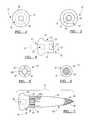
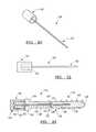
- FIG. 1illustrates an exploded view of an orthopedic fixation system, in accordance with one embodiment of the present invention
- FIG. 2illustrates a top plan view of the proximal portion of the orthopedic fixation system depicted in FIG. 1, in accordance with one embodiment of the present invention
- FIG. 3illustrates a bottom plan view of the proximal portion of the orthopedic fixation system depicted in FIG. 1, in accordance with one embodiment of the present invention
- FIG. 4illustrates an elevational view of the proximal portion of the orthopedic fixation system depicted in FIG. 1, in accordance with one embodiment of the present invention
- FIG. 5illustrates a top plan view of the distal portion of the orthopedic fixation system depicted in FIG. 1, in accordance with one embodiment of the present invention
- FIG. 6illustrates a bottom plan view of the distal portion of the orthopedic fixation system depicted in FIG. 1, in accordance with one embodiment of the present invention
- FIG. 7illustrates an elevational view of the proximal and distal portions of the orthopedic fixation system depicted in FIG. 1 in abutting engagement, in accordance with one embodiment of the present invention
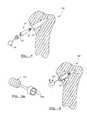
- FIG. 8illustrates a partial sectional view of a distal portion of an orthopedic fixation system about to be inserted into a fracture site of a femur head, in accordance with one embodiment of the present invention
- FIG. 8Aillustrates a perspective view of a driver member, in accordance with one embodiment of the present invention.
- FIG. 9illustrates a partial sectional view of a distal portion of an orthopedic fixation system partially inserted into a fracture site of a femur head, in accordance with one embodiment of the present invention
- FIG. 10illustrates a partial sectional view of a distal portion of an orthopedic fixation system fully inserted into a fracture site of a femur head, in accordance with one embodiment of the present invention
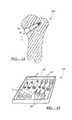
- FIG. 11illustrates a partial sectional view of a proximal portion of an orthopedic fixation system being inserted onto the distal portion of the orthopedic fixation system, in accordance with one embodiment of the present invention
- FIG. 12illustrates a partial sectional view of a fully inserted orthopedic fixation system, in accordance with one embodiment of the present invention
- FIG. 13illustrates a perspective view of a kit containing various sizes of the components of the orthopedic fixation system as well as the driver member, in accordance with one embodiment of the present invention.
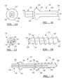
- FIG. 14illustrates an exploded view of an orthopedic fixation system, in accordance with an alternative embodiment of the present invention.
- FIG. 15illustrates a top plan view of the proximal portion of the orthopedic fixation system depicted in FIG. 14, in accordance with an alternative embodiment of the present invention
- FIG. 16illustrates an elevational view of the proximal portion of the orthopedic fixation system depicted in FIG. 14, in accordance with an alternative embodiment of the present invention
- FIG. 17illustrates a top plan view of the distal portion of the orthopedic fixation system depicted in FIG. 14, in accordance with an alternative embodiment of the present invention
- FIG. 18illustrates an elevational view of the distal portion of the orthopedic fixation system depicted in FIG. 14, in accordance with an alternative embodiment of the present invention
- FIG. 19illustrates an elevational view of the proximal and distal portions of the orthopedic fixation system depicted in FIG. 14 in abutting engagement, in accordance with an alternative embodiment of the present invention
- FIG. 20illustrates a perspective view of an insertion member, in accordance with an alternative embodiment of the present invention.
- FIG. 21illustrates an elevational view of the insertion member depicted in FIG. 20, in accordance with an alternative embodiment of the present invention
- FIG. 22illustrates an elevational view of the proximal and distal portions of the orthopedic fixation system depicted in FIG. 1, and the driver member depicted in FIGS. 20-21, in abutting engagement, in accordance with an alternative embodiment of the present invention
- FIG. 23illustrates a partial sectional view of an orthopedic fixation system about to be inserted into a fracture site of a femur head, in accordance with an alternative embodiment of the present invention
- FIG. 24illustrates a partial sectional view of an orthopedic fixation system partially inserted into a fracture site of a femur head, in accordance with an alternative embodiment of the present invention
- FIG. 25illustrates a partial sectional view of an orthopedic fixation system fully inserted into a fracture site of a femur head, in accordance with an alternative embodiment of the present invention
- FIG. 26illustrates a partial sectional view of a driver member being removed from a fully inserted orthopedic fixation system, in accordance with an alternative embodiment of the present invention
- FIG. 27illustrates a partial sectional view of a fully inserted orthopedic fixation system wherein the optional insertion facilitation member has been removed, in accordance with an alternative embodiment of the present invention.
- FIG. 28illustrates a perspective view of a kit containing various sizes of the components of the orthopedic fixation system as well as the driver member, in accordance with an alternative embodiment of the present invention.
- FIGS. 1-7there is generally shown an orthopedic fixation system 10 , in accordance with one embodiment of the present invention.
- a surgical or bone screwis shown for illustrative purposes, it should be appreciated that any number of different types of surgical devices, such as surgical fasteners, may be practiced with the present invention, including, but not limited to plates, rods, pins, staples.
- the system 10primarily includes a proximal portion 12 comprised of a bioresorbable material 14 and a distal portion 16 comprised of a non-resorbable material 18 .
- Distal portion 16is substantially elongated as compared to proximal portion 12 .
- Bioresorbable material 14is preferably comprised of materials selected from the group consisting of hydroxyapatite, polylactic acid, polyglycolic acid, and combinations thereof.
- Non- resorbable material 18is preferably comprised of materials selected from the group consisting of stainless steel, titanium, cobalt-chrome alloys, and combinations thereof.
- Proximal portion 12includes a proximal region 20 and a spaced and opposed distal region 22 .
- Proximal region 20includes a shaft-like portion 24 extending from distal region 22 towards proximal region 20 .
- an adjacent and contiguous head portion 26is provided.
- Disposed on the proximal surface of head portion 26is a recess 28 which is intended to receive a driver member, as will be explained later.
- an optional raised membersuch as a hex-shaped member 29 , shown in phantom in FIG. 4, may used to engage a driver member.
- Disposed on the distal surface of shaft portion 24is another recess 30 , which preferably has a threaded surface 32 thereon, the purpose of which will be explained later.
- Distal portion 16also includes a proximal region 34 and a spaced and opposed distal region 36 .
- An external threaded surface 38is provided on the distal region 36 of distal portion 16 , and is intended to function as a cutting surface for permitting insertion into tissue, such as, but not limited to bone tissue.
- Proximal region 34preferably includes a mating member 40 which is intended to selectively mate with recess 30 of proximal portion 12 .
- mating member 40is provided with a threaded surface 42 thereon which corresponds to threaded surface 32 of recess 30 . Accordingly, the respective configurations of recess 32 and mating member 40 should be complementary towards one another.
- mating member 40 and recess 32are shown as being circular and threaded, other configurations are envisioned, as well. Furthermore, a snap-fit appendage (not shown) may be provided on mating member 40 that snaps into a further recess (not shown) on the surface wall of recess 32 .
- System 10is unique in that proximal portion 12 and distal portion 16 need not be joined together (as shown in FIG. 7) in order to initiate the insertion of system 10 into tissue, such as bone tissue, in order to join two bone fragments together, to attach an orthopedic appliance (e.g., bone plate) to and/or into a bone surface, or to accomplish any other suitable orthopedic procedure. That is, distal portion 16 may first be inserted, either partially or substantially completely, and then proximal portion 12 may then be joined to distal portion 16 , whereupon system 10 is then fully and completely inserted.
- tissuesuch as bone tissue
- an orthopedic appliancee.g., bone plate
- a rotation facilitation and release facilitation system 34 ais preferably provided on the proximal surface of proximal region 34 .
- rotation facilitation and release facilitation system 34 apreferably includes at least one, preferably at least two, and still more preferably, at least three areas defining recesses 34 b located in the proximal surface of the proximal region 34 .
- these recesses 34 bcan mate with a three-pronged driver member 104 having three matching prongs 104 a which can then rotate and insert distal portion 16 and then can be easily removed from recesses 34 b by simply pulling outwardly away therefrom. In this manner, there is no need to engage threaded mating member 40 .
- mating member 40may be configured as a hex-shaped member, or other suitable configuration, that is capable of disengaging from a corresponding driver member without causing distal member 16 to rotate once inserted into the bone tissue.
- FIG. 8there is shown a fractured femur head 100 having a pilot hole 102 pre-drilled for receiving the orthopedic fixation system 10 .
- a suitable driver 104is shown which preferably mates with recesses 34 b , or alternatively, mating member 40 .
- driver member 104is rotated in direction R (e.g., clockwise) so as to cause distal portion 16 to be driven into pilot hole 102 .
- the torque generated by the rotationacts exclusively on distal portion 16 as it cuts through the bone tissue adjacent to pilot hole 102 .
- driver member 104can be fitted which a device to create a countersink in the surface of the bone tissue.
- distal portion 16has been substantially fully inserted into pilot hole 102 . Note that distal portion 16 extends across both portions of the fracture site, providing outstanding physical support for the fracture site in which proper healing can take place.
- proximal portion 12is mated to distal portion 16 and another driver member 106 is used to rotate proximal portion 12 in direction RR so as to cause both proximal portion 12 and distal portion 16 to be inserted slightly more into pilot hole 102 until system 10 can no longer be inserted any further into the bone tissue.
- system 10is shown in its fully inserted position, with head portion 26 of proximal portion 12 being substantially co-planar with the surface of the bone tissue, thus eliminating any tissue irritation concerns previously discussed.
- Proximal portion 12will eventually be resorbed by the body over time. New bone tissue will eventually grow into the portion of pilot hole 102 occupied by proximal portion 102 , as it gradually resorbs.
- head portion 26need not be completely countersunk into the bone tissue, as shown. Occasionally, head portion 26 may protrude slightly above the surface of the bone tissue. Generally, this is not an undesirable condition, as head portion 26 will eventually be resorbed.
- surgeonmay optionally either remove the protruding portion (e.g., with a heat loop or a cutting tool such as a burr) or alternatively, melt the protruding portion so that it assumes a lower profile against the surface of the bone tissue.
- remove the protruding portione.g., with a heat loop or a cutting tool such as a burr
- melt the protruding portionso that it assumes a lower profile against the surface of the bone tissue.
- the present inventioncan also be used to affix or fasten orthopedic appliances, such as bone plates and the like, to and/or into bone surfaces.
- the orthopedic fixation system of the present inventionwould be simply driven through the orthopedic appliance (or a provided hole therein), by rotating the various driver members of the present invention, and into the respective bone surface.
- the orthopedic fixation system of the present inventioncan be used with resorbable, as well as non-resorbable, orthopedic appliances.
- Kit 200includes a receptacle 202 which can neatly, and preferably sterilely, store any number of different size component/driver so that the orthopedic surgeon can have his/her choice as to which size component/driver is appropriate to use.
- a fracture of a relatively small bonemay require a relatively small orthopedic fixation system 10
- a large bonee.g., a femur or tibia
- Kit 200provides the surgeon with any number of choices as how to approach the orthopedic procedure presented to him/her.
- FIGS. 14-19there is generally shown an alternative orthopedic fixation system 110 , in accordance with an alternative embodiment of the present invention.
- a surgical or bone screwis shown for illustrative purposes, it should be appreciated that any number of different types of surgical devices, such as surgical fasteners, may be practiced with the present invention, including, but not limited to plates, rods, pins, staples.
- System 110primarily includes a proximal portion 112 comprised of a bioresorbable material 114 and a distal portion 116 comprised of a non-resorbable material 118 .
- Bioresorbable material 114is preferably comprised of materials selected from the group consisting of hydroxyapatite, polylactic acid, polyglycolic acid, and combinations thereof.
- Non-resorbable material 118is preferably comprised of materials selected from the group consisting of stainless steel, titanium, cobalt-chrome alloys, and combinations thereof.
- Proximal portion 112includes a proximal region 120 and a spaced and opposed distal region 122 .
- Proximal region 120includes a shaft-like portion 124 extending from distal region 122 towards proximal region 120 .
- shaft portion 124nears proximal region 120 , an adjacent and contiguous head portion 126 is provided.
- head portion 126Extending above head portion 126 is an optional insertion facilitation member 128 , the purpose of which will be explained later.
- proximal portion 112Extending along the longitudinal axis of proximal portion 112 is a throughbore 130 .
- a recess 134At the distal surface 132 of proximal member 112 is a recess 134 , the purpose of which will be explained later.
- Distal portion 116also includes a proximal region 136 and a spaced and opposed distal region 138 .
- An external threaded surface 140is provided on substantially the entire external surface of distal portion 116 , and is intended to function as a cutting surface for permitting insertion into tissue, such as, but not limited to bone tissue.
- Proximal region 136includes a mating member 142 which is intended to selectively mate with recess 134 of proximal portion 112 . Accordingly, the respective configurations of recess 134 and mating member 142 should be complementary towards one another. Although mating member 142 and recess 134 are shown as being rectangular, other configurations are envisioned, as well. Furthermore, a snap-fit appendage (not shown) may be provided on mating member 142 that snaps into a further recess (not shown) on the surface wall of recess 134 .
- a bore 144Extending along the longitudinal axis of distal portion 116 is a bore 144 , which originated on the top surface of mating member 142 and extends approximately halfway along the length of distal portion 116 .
- throughbore 130preferably aligns with bore 144 , as specifically shown in FIG. 19 .
- proximal portion 112 and distal portion 116are joined together (as shown in FIG. 19) it is then possible to insert system 110 into tissue, such as bone tissue, in order to join two bone fragments together, to attach an orthopedic appliance (e.g., bone plate) to and/or into a bone surface, or to accomplish any other suitable orthopedic procedure.
- tissuesuch as bone tissue
- an orthopedic appliancee.g., bone plate
- the present inventionendeavors to substantially reduce the amount of stress, especially torque stresses and forces, imparted onto the bioresorbable portion of the fixation system. In this manner, the present invention greatly reduces the incidences of catastrophic failure of the bioresorbable portion of the fixation system.
- the present inventionprovides a specialized driver member that imparts the greatest stresses and torque forces on the portion of the fixation system that is best suited to absorb these forces and stresses, i.e., the non-resorbable distal portion.
- a driver member 146includes a cap portion 148 and an elongated appendage portion 150 extending from an internal surface 152 of cap portion 148 .
- elongated appendage portion 150The purpose of elongated appendage portion 150 is to engage an internal surface of bore 144 of distal portion 116 .
- elongated appendage portion 150can also engage an internal surface of throughbore 130 of proximal portion 112 .
- elongated appendage portion 150In order for elongated appendage portion 150 to be able to engage an internal surface of bore 144 of distal portion 116 , it must first be inserted into throughbore 130 of proximal portion 112 and then preferably fully inserted into bore 144 of distal portion 116 .
- bore 144is preferably provided with an anti-rotation device 154 , such as, but not limited to a rectangular or hex-shaped internal surface, as opposed to a circular internal surface.
- elongated appendage portion 150is provided with a complementary external surface that corresponds to the internal surface of bore 144 .
- elongated appendage portion 150should be hex-shaped, if bore 144 is rectangularly-shaped, elongated appendage portion 150 should be rectangularly-shaped, and so forth.
- throughbore 130may also be adapted to engage elongated appendage portion 150 , as well.
- throughbore 130should be hex-shaped
- throughbore 130should be rectangularly-shaped
- throughbore 130should be rectangularly-shaped, and so forth.
- itmay optionally be provided with a slightly larger diameter than the diameter of elongated appendage portion 150 so as to avoid any contact therewith.
- Internal surface 152 of cap portion 148is substantially hollow, with the exception of elongated appendage portion 150 emanating therefrom. Because it is hollow, it is able to snuggly fit over optional insertion facilitation member 128 , although not so snuggly that driver member 146 can not be easily removed. In this manner, as driver member 146 is rotated, the torque generated will substantially be acting on optional insertion facilitation member 128 and to a much greater degree upon distal portion 116 , as opposed to proximal portion 112 .
- driver member 146will not wobble, because it is held snuggly by bore 144 of distal portion 116 and internal surface 152 of cap 148 is held snuggly against optional insertion facilitation member 128 . Therefore, the probability that a catastrophic failure of proximal portion 112 will occur at the interface between proximal portion 112 and distal portion 116 is greatly reduced.
- FIG. 23there is shown a fractured femur head 200 having a pilot hole 202 pre-drilled for receiving the orthopedic fixation system 110 .
- proximal portion 112 and distal portion 116are joined together with driver member 146 associated therewith.
- driver member 146is rotated in direction R (e.g., clockwise) so as to cause orthopedic fixation system 110 to be driven into pilot hole 202 .
- the torque generated by the rotationacts primarily on distal portion 116 as it cuts through the bone tissue adjacent to pilot hole 202 .
- driver member 146can no longer be rotated anymore, indicating that orthopedic fixation system 110 has been fully inserted into pilot hole 202 .
- driver member 146is removed from orthopedic fixation system 110 by applying a gentle pulling force in direction P, exposing elongated appendage portion 150 .
- optional insertion facilitation member 128may optionally be removed (e.g., with a heat loop), if the clinical setting requires so. Otherwise, optional insertion facilitation member 128 , as well as proximal portion 112 , will eventually be resorbed by the body over time. New bone tissue will eventually grow into the portion of pilot hole 202 occupied by proximal portion 112 , as it gradually resorbs.
- the present inventioncan also be used to affix or fasten orthopedic appliances, such as bioresorbable bone plates and the like, to and/or into bone surfaces.
- the orthopedic fixation system of the present inventionwould be simply driven through the resorbable orthopedic appliance (or a provided hole therein), by rotating the driver member of the present invention, and into the respective bone surface. After insertion is complete, the driver member of the present invention would be removed from the orthopedic fixation system of the present invention. As the resorbable orthopedic appliance resorbs, the resorbable portion of the orthopedic fixation system of the present invention would also resorb, although perhaps at a slower rate to prevent premature detachment of the resorbable orthopedic appliance from the bone surface.
- Kit 300includes a receptacle 302 which can neatly, and preferably sterilely, store any number of different size component/driver so that the orthopedic surgeon can have his/her choice as to which size component/driver is appropriate to use.
- a fracture of a relatively small bonemay require a relatively small orthopedic fixation system 110
- a large bonee.g., a femur or tibia
- Kit 300provides the surgeon with any number of choices as how to approach the orthopedic procedure presented to him/her.
Landscapes
- Health & Medical Sciences (AREA)
- Orthopedic Medicine & Surgery (AREA)
- Surgery (AREA)
- Life Sciences & Earth Sciences (AREA)
- Heart & Thoracic Surgery (AREA)
- Nuclear Medicine, Radiotherapy & Molecular Imaging (AREA)
- Engineering & Computer Science (AREA)
- Biomedical Technology (AREA)
- Medical Informatics (AREA)
- Molecular Biology (AREA)
- Animal Behavior & Ethology (AREA)
- General Health & Medical Sciences (AREA)
- Public Health (AREA)
- Veterinary Medicine (AREA)
- Neurology (AREA)
- Surgical Instruments (AREA)
Abstract
Description
Claims (64)
Priority Applications (1)
| Application Number | Priority Date | Filing Date | Title |
|---|---|---|---|
| US09/853,425US6471707B1 (en) | 2001-05-11 | 2001-05-11 | Bone screw having bioresorbable proximal shaft portion |
Applications Claiming Priority (1)
| Application Number | Priority Date | Filing Date | Title |
|---|---|---|---|
| US09/853,425US6471707B1 (en) | 2001-05-11 | 2001-05-11 | Bone screw having bioresorbable proximal shaft portion |
Publications (1)
| Publication Number | Publication Date |
|---|---|
| US6471707B1true US6471707B1 (en) | 2002-10-29 |
Family
ID=25316005
Family Applications (1)
| Application Number | Title | Priority Date | Filing Date |
|---|---|---|---|
| US09/853,425Expired - LifetimeUS6471707B1 (en) | 2001-05-11 | 2001-05-11 | Bone screw having bioresorbable proximal shaft portion |
Country Status (1)
| Country | Link |
|---|---|
| US (1) | US6471707B1 (en) |
Cited By (154)
| Publication number | Priority date | Publication date | Assignee | Title |
|---|---|---|---|---|
| US20010042099A1 (en)* | 2000-02-02 | 2001-11-15 | Doongo Technologies, Inc. | Apparatus and methods for optimizing traffic volume in wireless email communications |
| US20030125744A1 (en)* | 2001-12-27 | 2003-07-03 | Ethicon, Inc. | Polymer-based orthopedic screw and driver system with increased insertion torque tolerance and associated method for making and using same |
| US20030125749A1 (en)* | 2001-12-27 | 2003-07-03 | Ethicon, Inc. | Cannulated screw and associated driver system |
| US6692507B2 (en)* | 2001-08-23 | 2004-02-17 | Scimed Life Systems, Inc. | Impermanent biocompatible fastener |
| US20040098722A1 (en)* | 2002-08-09 | 2004-05-20 | International Business Machines Corporation | System, method, and computer program product for operating-system task management |
| US20040102780A1 (en)* | 2002-11-26 | 2004-05-27 | West Hugh S. | Protective devices for use with angled interference screws |
| US20040122431A1 (en)* | 2002-10-04 | 2004-06-24 | Lutz Biedermann | Bone screw and bone screw with holding element |
| US6916321B2 (en)* | 2001-09-28 | 2005-07-12 | Ethicon, Inc. | Self-tapping resorbable two-piece bone screw |
| US20050251264A1 (en)* | 2004-05-04 | 2005-11-10 | Biopro. Inc. | Subtalar implant |
| US20050277926A1 (en)* | 2004-06-15 | 2005-12-15 | Farris Robert A | Spinal rod system |
| US20060041315A1 (en)* | 2004-05-04 | 2006-02-23 | Biopro, Inc. | Subtalar implant |
| US20070037096A1 (en)* | 2003-09-30 | 2007-02-15 | Dai Nippon Printing Co. Ltd. | Photo radical generator, photo sensitive resin composition and article |
| US7235079B2 (en) | 2004-11-18 | 2007-06-26 | Acumed Llc | Composite bone fasteners |
| US20070156153A1 (en)* | 2005-12-29 | 2007-07-05 | Industrial Technology Research Institute | Device and method for fixing soft tissue |
| US20070270859A1 (en)* | 2006-04-28 | 2007-11-22 | Sdgi Holdings, Inc. | Orthopedic screw with break away drive |
| EP1859753A2 (en) | 2006-05-24 | 2007-11-28 | Bioretec Oy | A system to be used with an implanting tool |
| US7331982B1 (en) | 2003-09-08 | 2008-02-19 | Biomet Sports Medicine, Inc. | Suture anchor and associated method |
| US20080045627A1 (en)* | 2003-07-19 | 2008-02-21 | John Rose | High Strength Bioreabsorbable Co-Polymers |
| JP2008508979A (en)* | 2004-08-09 | 2008-03-27 | マーク エー. レイリー, | System and method for bone fixation or fusion |
| EP1967151A1 (en)* | 2007-03-06 | 2008-09-10 | Zimmer Technology, Inc. | Self tapping screw with resorbable tip |
| US7455674B2 (en) | 2002-01-31 | 2008-11-25 | Smith & Nephew Plc | High strength bioresorbables containing poly-glycolic acid |
| US7524891B2 (en) | 2001-07-04 | 2009-04-28 | Smith & Nephew Plc | Biodegradable polymer systems |
| US7601165B2 (en) | 2006-09-29 | 2009-10-13 | Biomet Sports Medicine, Llc | Method and apparatus for forming a self-locking adjustable suture loop |
| US7608098B1 (en) | 2004-11-09 | 2009-10-27 | Biomet Sports Medicine, Llc | Bone fixation device |
| US7608092B1 (en) | 2004-02-20 | 2009-10-27 | Biomet Sports Medicince, LLC | Method and apparatus for performing meniscus repair |
| US20100042162A1 (en)* | 2008-08-12 | 2010-02-18 | Warsaw Orthopedic, Inc. | Self-locking surgical fastener |
| US20100106199A1 (en)* | 2008-06-16 | 2010-04-29 | Sawa Anna G U | Venting/pressure adjustment to aid in delivery of material into an anatomic region via a cannula |
| EP2198796A1 (en)* | 2008-12-19 | 2010-06-23 | Sepitec Foundation | Bone screw |
| US7749250B2 (en) | 2006-02-03 | 2010-07-06 | Biomet Sports Medicine, Llc | Soft tissue repair assembly and associated method |
| US20100249944A1 (en)* | 2009-03-31 | 2010-09-30 | Thomas Jonathan D | Multizone Implants |
| US7857830B2 (en) | 2006-02-03 | 2010-12-28 | Biomet Sports Medicine, Llc | Soft tissue repair and conduit device |
| US7905903B2 (en) | 2006-02-03 | 2011-03-15 | Biomet Sports Medicine, Llc | Method for tissue fixation |
| US7905904B2 (en) | 2006-02-03 | 2011-03-15 | Biomet Sports Medicine, Llc | Soft tissue repair device and associated methods |
| US7909851B2 (en) | 2006-02-03 | 2011-03-22 | Biomet Sports Medicine, Llc | Soft tissue repair device and associated methods |
| US7914539B2 (en) | 2004-11-09 | 2011-03-29 | Biomet Sports Medicine, Llc | Tissue fixation device |
| US20110118790A1 (en)* | 2004-08-09 | 2011-05-19 | Si-Bone, Inc. | Apparatus, systems, and methods for stablizing a spondylolisthesis |
| US20110118785A1 (en)* | 2004-08-09 | 2011-05-19 | Si-Bone, Inc. | Apparatus, systems, and methods for achieving anterior lumbar interbody fusion |
| US20110137349A1 (en)* | 2005-04-12 | 2011-06-09 | Moskowitz Nathan C | Horizontal-transvertebral curvilinear nail-screws with inter-locking rigid or jointed flexible rods for spinal fusion |
| US7959650B2 (en) | 2006-09-29 | 2011-06-14 | Biomet Sports Medicine, Llc | Adjustable knotless loops |
| US8016865B2 (en) | 2003-09-29 | 2011-09-13 | Depuy Mitek, Inc. | Method of performing anterior cruciate ligament reconstruction using biodegradable interference screw |
| US20110224738A1 (en)* | 2005-05-10 | 2011-09-15 | Acumed Llc | Bone connector with pivotable joint |
| US8034090B2 (en) | 2004-11-09 | 2011-10-11 | Biomet Sports Medicine, Llc | Tissue fixation device |
| US20110270312A1 (en)* | 2003-10-23 | 2011-11-03 | Trans1 Inc. | Spinal implant |
| US8088130B2 (en) | 2006-02-03 | 2012-01-03 | Biomet Sports Medicine, Llc | Method and apparatus for coupling soft tissue to a bone |
| US8118836B2 (en) | 2004-11-05 | 2012-02-21 | Biomet Sports Medicine, Llc | Method and apparatus for coupling soft tissue to a bone |
| US8128658B2 (en) | 2004-11-05 | 2012-03-06 | Biomet Sports Medicine, Llc | Method and apparatus for coupling soft tissue to bone |
| US8137382B2 (en) | 2004-11-05 | 2012-03-20 | Biomet Sports Medicine, Llc | Method and apparatus for coupling anatomical features |
| US8251998B2 (en) | 2006-08-16 | 2012-08-28 | Biomet Sports Medicine, Llc | Chondral defect repair |
| JP2012521800A (en)* | 2009-03-24 | 2012-09-20 | スタビリッツ オルトペディクス, エルエルシー | Orthopedic fixation device having a bioresorbable material layer |
| USD668338S1 (en)* | 2010-11-11 | 2012-10-02 | Gautheir Biomedical, Inc. | Tool implement release collar |
| US8298262B2 (en) | 2006-02-03 | 2012-10-30 | Biomet Sports Medicine, Llc | Method for tissue fixation |
| US8303604B2 (en) | 2004-11-05 | 2012-11-06 | Biomet Sports Medicine, Llc | Soft tissue repair device and method |
| US8317825B2 (en) | 2004-11-09 | 2012-11-27 | Biomet Sports Medicine, Llc | Soft tissue conduit device and method |
| US8343227B2 (en) | 2009-05-28 | 2013-01-01 | Biomet Manufacturing Corp. | Knee prosthesis assembly with ligament link |
| US8361113B2 (en) | 2006-02-03 | 2013-01-29 | Biomet Sports Medicine, Llc | Method and apparatus for coupling soft tissue to a bone |
| US8361123B2 (en) | 2009-10-16 | 2013-01-29 | Depuy Spine, Inc. | Bone anchor assemblies and methods of manufacturing and use thereof |
| US8361129B2 (en) | 2006-04-28 | 2013-01-29 | Depuy Spine, Inc. | Large diameter bone anchor assembly |
| US8388667B2 (en) | 2004-08-09 | 2013-03-05 | Si-Bone, Inc. | Systems and methods for the fixation or fusion of bone using compressive implants |
| US8414648B2 (en) | 2004-08-09 | 2013-04-09 | Si-Bone Inc. | Apparatus, systems, and methods for achieving trans-iliac lumbar fusion |
| US8444693B2 (en) | 2004-08-09 | 2013-05-21 | Si-Bone Inc. | Apparatus, systems, and methods for achieving lumbar facet fusion |
| US8500818B2 (en) | 2006-09-29 | 2013-08-06 | Biomet Manufacturing, Llc | Knee prosthesis assembly with ligament link |
| US8506597B2 (en) | 2011-10-25 | 2013-08-13 | Biomet Sports Medicine, Llc | Method and apparatus for interosseous membrane reconstruction |
| US20130218214A1 (en)* | 2012-01-16 | 2013-08-22 | Carbofix Orthopedics Ltd. | Bone screw head design |
| US8562647B2 (en) | 2006-09-29 | 2013-10-22 | Biomet Sports Medicine, Llc | Method and apparatus for securing soft tissue to bone |
| US8562645B2 (en) | 2006-09-29 | 2013-10-22 | Biomet Sports Medicine, Llc | Method and apparatus for forming a self-locking adjustable loop |
| US8574235B2 (en) | 2006-02-03 | 2013-11-05 | Biomet Sports Medicine, Llc | Method for trochanteric reattachment |
| US8597327B2 (en) | 2006-02-03 | 2013-12-03 | Biomet Manufacturing, Llc | Method and apparatus for sternal closure |
| US8652172B2 (en) | 2006-02-03 | 2014-02-18 | Biomet Sports Medicine, Llc | Flexible anchors for tissue fixation |
| US8652171B2 (en) | 2006-02-03 | 2014-02-18 | Biomet Sports Medicine, Llc | Method and apparatus for soft tissue fixation |
| US8672969B2 (en) | 2006-09-29 | 2014-03-18 | Biomet Sports Medicine, Llc | Fracture fixation device |
| US8771352B2 (en) | 2011-05-17 | 2014-07-08 | Biomet Sports Medicine, Llc | Method and apparatus for tibial fixation of an ACL graft |
| US8778026B2 (en) | 2012-03-09 | 2014-07-15 | Si-Bone Inc. | Artificial SI joint |
| US8801783B2 (en) | 2006-09-29 | 2014-08-12 | Biomet Sports Medicine, Llc | Prosthetic ligament system for knee joint |
| US8840645B2 (en) | 2004-11-05 | 2014-09-23 | Biomet Sports Medicine, Llc | Method and apparatus for coupling soft tissue to a bone |
| WO2014153167A1 (en)* | 2013-03-14 | 2014-09-25 | The Raph Life, Llc | Surgical system device without the use of a guide wire |
| US20140343616A1 (en)* | 2013-04-22 | 2014-11-20 | Daniel Sellers | Arthrodesis compression device |
| US8936621B2 (en) | 2006-02-03 | 2015-01-20 | Biomet Sports Medicine, Llc | Method and apparatus for forming a self-locking adjustable loop |
| US8968364B2 (en) | 2006-02-03 | 2015-03-03 | Biomet Sports Medicine, Llc | Method and apparatus for fixation of an ACL graft |
| US8998949B2 (en) | 2004-11-09 | 2015-04-07 | Biomet Sports Medicine, Llc | Soft tissue conduit device |
| US9017381B2 (en) | 2007-04-10 | 2015-04-28 | Biomet Sports Medicine, Llc | Adjustable knotless loops |
| US9044321B2 (en) | 2012-03-09 | 2015-06-02 | Si-Bone Inc. | Integrated implant |
| US9078644B2 (en) | 2006-09-29 | 2015-07-14 | Biomet Sports Medicine, Llc | Fracture fixation device |
| US9101417B2 (en) | 2009-01-16 | 2015-08-11 | Carbofix Orthopedics Ltd. | Composite material bone implant |
| US20150238232A1 (en)* | 2004-04-16 | 2015-08-27 | Biedermann Technologies Gmbh & Co. Kg | Elastic element for the use in a stabilization device for bones and vertebrae and method for the manufacture of such elastic element |
| US9120919B2 (en) | 2003-12-23 | 2015-09-01 | Smith & Nephew, Inc. | Tunable segmented polyacetal |
| US9149267B2 (en) | 2006-02-03 | 2015-10-06 | Biomet Sports Medicine, Llc | Method and apparatus for coupling soft tissue to a bone |
| US9259217B2 (en) | 2012-01-03 | 2016-02-16 | Biomet Manufacturing, Llc | Suture Button |
| US9265551B2 (en) | 2013-07-19 | 2016-02-23 | Pro-Dex, Inc. | Torque-limiting screwdrivers |
| US9271713B2 (en) | 2006-02-03 | 2016-03-01 | Biomet Sports Medicine, Llc | Method and apparatus for tensioning a suture |
| US9314241B2 (en) | 2011-11-10 | 2016-04-19 | Biomet Sports Medicine, Llc | Apparatus for coupling soft tissue to a bone |
| US9357991B2 (en) | 2011-11-03 | 2016-06-07 | Biomet Sports Medicine, Llc | Method and apparatus for stitching tendons |
| US9370388B2 (en) | 2010-06-07 | 2016-06-21 | Carbofix Orthopedics Ltd. | Composite material bone implant |
| US9370350B2 (en) | 2011-11-10 | 2016-06-21 | Biomet Sports Medicine, Llc | Apparatus for coupling soft tissue to a bone |
| US9381013B2 (en) | 2011-11-10 | 2016-07-05 | Biomet Sports Medicine, Llc | Method for coupling soft tissue to a bone |
| US9381096B2 (en) | 2012-09-13 | 2016-07-05 | Biomet Manufacturing, Llc | Method and apparatus to identify coordinated components |
| WO2016125054A1 (en)* | 2015-02-03 | 2016-08-11 | Biomech Innovations Sa | Device for variable fixation of bone fragments |
| US9526549B2 (en) | 2012-01-16 | 2016-12-27 | Carbofix Orthopedics Ltd. | Bone screw with insert |
| US9538998B2 (en) | 2006-02-03 | 2017-01-10 | Biomet Sports Medicine, Llc | Method and apparatus for fracture fixation |
| US9615822B2 (en) | 2014-05-30 | 2017-04-11 | Biomet Sports Medicine, Llc | Insertion tools and method for soft anchor |
| US9622783B2 (en) | 2004-08-09 | 2017-04-18 | Si-Bone Inc. | Systems and methods for the fixation or fusion of bone |
| US9662157B2 (en) | 2014-09-18 | 2017-05-30 | Si-Bone Inc. | Matrix implant |
| US9662158B2 (en) | 2004-08-09 | 2017-05-30 | Si-Bone Inc. | Systems and methods for the fixation or fusion of bone at or near a sacroiliac joint |
| US9700291B2 (en) | 2014-06-03 | 2017-07-11 | Biomet Sports Medicine, Llc | Capsule retractor |
| US9757119B2 (en) | 2013-03-08 | 2017-09-12 | Biomet Sports Medicine, Llc | Visual aid for identifying suture limbs arthroscopically |
| US9801708B2 (en) | 2004-11-05 | 2017-10-31 | Biomet Sports Medicine, Llc | Method and apparatus for coupling soft tissue to a bone |
| US9839448B2 (en) | 2013-10-15 | 2017-12-12 | Si-Bone Inc. | Implant placement |
| US9918827B2 (en) | 2013-03-14 | 2018-03-20 | Biomet Sports Medicine, Llc | Scaffold for spring ligament repair |
| US9918826B2 (en) | 2006-09-29 | 2018-03-20 | Biomet Sports Medicine, Llc | Scaffold for spring ligament repair |
| US9936983B2 (en) | 2013-03-15 | 2018-04-10 | Si-Bone Inc. | Implants for spinal fixation or fusion |
| US9949843B2 (en) | 2004-08-09 | 2018-04-24 | Si-Bone Inc. | Apparatus, systems, and methods for the fixation or fusion of bone |
| US9955980B2 (en) | 2015-02-24 | 2018-05-01 | Biomet Sports Medicine, Llc | Anatomic soft tissue repair |
| US10039543B2 (en) | 2014-08-22 | 2018-08-07 | Biomet Sports Medicine, Llc | Non-sliding soft anchor |
| CN108403199A (en)* | 2018-01-25 | 2018-08-17 | 吴旋 | Arthroscopic surface helix locking structure |
| US10136886B2 (en) | 2013-12-20 | 2018-11-27 | Biomet Sports Medicine, Llc | Knotless soft tissue devices and techniques |
| US10154867B2 (en) | 2010-06-07 | 2018-12-18 | Carbofix In Orthopedics Llc | Multi-layer composite material bone screw |
| US10166033B2 (en) | 2014-09-18 | 2019-01-01 | Si-Bone Inc. | Implants for bone fixation or fusion |
| US10363140B2 (en) | 2012-03-09 | 2019-07-30 | Si-Bone Inc. | Systems, device, and methods for joint fusion |
| US10376206B2 (en) | 2015-04-01 | 2019-08-13 | Si-Bone Inc. | Neuromonitoring systems and methods for bone fixation or fusion procedures |
| US10383674B2 (en) | 2016-06-07 | 2019-08-20 | Pro-Dex, Inc. | Torque-limiting screwdriver devices, systems, and methods |
| US10426533B2 (en) | 2012-05-04 | 2019-10-01 | Si-Bone Inc. | Fenestrated implant |
| US10517587B2 (en) | 2006-02-03 | 2019-12-31 | Biomet Sports Medicine, Llc | Method and apparatus for forming a self-locking adjustable loop |
| WO2020068933A1 (en)* | 2018-09-25 | 2020-04-02 | The Board Of Supervisors Of Louisiana State University And Agricultural And Mechanical College | Surgical line fixation device and methods of use thereof |
| US10617458B2 (en) | 2015-12-23 | 2020-04-14 | Carbofix In Orthopedics Llc | Multi-layer composite material bone screw |
| US10869954B2 (en) | 2016-03-07 | 2020-12-22 | Ossio, Ltd. | Surface treated biocomposite material, medical implants comprising same and methods of treatment thereof |
| US10869708B2 (en) | 2014-09-07 | 2020-12-22 | Ossio, Ltd. | Anisotropic biocomposite material, medical implants comprising same and methods of treatment thereof |
| US10912551B2 (en) | 2015-03-31 | 2021-02-09 | Biomet Sports Medicine, Llc | Suture anchor with soft anchor of electrospun fibers |
| US10926004B2 (en) | 2014-12-26 | 2021-02-23 | Ossio Ltd. | Continuous-fiber reinforced biocomposite medical implants |
| EP3854333A1 (en)* | 2020-01-22 | 2021-07-28 | Howmedica Osteonics Corp. | Femoral implant |
| US11090128B2 (en) | 2018-08-20 | 2021-08-17 | Pro-Dex, Inc. | Torque-limiting devices, systems, and methods |
| US11116519B2 (en) | 2017-09-26 | 2021-09-14 | Si-Bone Inc. | Systems and methods for decorticating the sacroiliac joint |
| US11147688B2 (en) | 2013-10-15 | 2021-10-19 | Si-Bone Inc. | Implant placement |
| US11234830B2 (en) | 2019-02-14 | 2022-02-01 | Si-Bone Inc. | Implants for spinal fixation and or fusion |
| US11259792B2 (en) | 2006-02-03 | 2022-03-01 | Biomet Sports Medicine, Llc | Method and apparatus for coupling anatomical features |
| US11259794B2 (en) | 2006-09-29 | 2022-03-01 | Biomet Sports Medicine, Llc | Method for implanting soft tissue |
| US11311287B2 (en) | 2006-02-03 | 2022-04-26 | Biomet Sports Medicine, Llc | Method for tissue fixation |
| WO2022103733A1 (en) | 2020-11-11 | 2022-05-19 | Acumed Llc | Variable pitch tapered compressing screw for dynamic compression |
| US11369419B2 (en) | 2019-02-14 | 2022-06-28 | Si-Bone Inc. | Implants for spinal fixation and or fusion |
| WO2022204774A1 (en)* | 2021-03-31 | 2022-10-06 | M3 Health Indústria E Comércio De Produtos Médicos, Odontológicos E Correlatos S.A. | Partially reabsorbabble medical implant and manufacturing process of such implant |
| US11491264B2 (en) | 2016-06-27 | 2022-11-08 | Ossio Ltd. | Fiber reinforced biocomposite medical implants with high mineral content |
| US11571245B2 (en) | 2019-11-27 | 2023-02-07 | Si-Bone Inc. | Bone stabilizing implants and methods of placement across SI joints |
| US11633292B2 (en) | 2005-05-24 | 2023-04-25 | Si-Bone Inc. | Apparatus, systems, and methods for the fixation or fusion of bone |
| US11752011B2 (en) | 2020-12-09 | 2023-09-12 | Si-Bone Inc. | Sacro-iliac joint stabilizing implants and methods of implantation |
| US20230285156A1 (en)* | 2022-03-11 | 2023-09-14 | University Of Maryland, Baltimore | Device and method for sacroiliac fusion |
| US11883296B2 (en) | 2016-11-07 | 2024-01-30 | Endospine, S.L. | Process of bone creation between adjacent vertebrae |
| US12083026B2 (en) | 2019-12-09 | 2024-09-10 | Si-Bone Inc. | Sacro-iliac joint stabilizing implants and methods of implantation |
| US12096928B2 (en) | 2009-05-29 | 2024-09-24 | Biomet Sports Medicine, Llc | Method and apparatus for coupling soft tissue to a bone |
| US12245759B2 (en) | 2008-08-22 | 2025-03-11 | Biomet Sports Medicine, Llc | Method and apparatus for coupling soft tissue to bone |
| US12295616B2 (en) | 2021-07-19 | 2025-05-13 | Ossio Ltd | Cannulated implant delivery device with adjustable insertion depth |
| WO2025117859A1 (en)* | 2023-11-28 | 2025-06-05 | Board Of Supervisors Of Louisiana State University And Agricultural And Mechanical College | Bone screw for dental applications |
| US12329373B2 (en) | 2011-05-02 | 2025-06-17 | Biomet Sports Medicine, Llc | Method and apparatus for soft tissue fixation |
| US12419632B2 (en) | 2008-08-22 | 2025-09-23 | Biomet Sports Medicine, Llc | Method and apparatus for coupling anatomical features |
| US12419668B2 (en) | 2019-11-21 | 2025-09-23 | Si-Bone Inc. | Rod coupling assemblies for bone stabilization constructs |
| US12427028B2 (en) | 2018-03-28 | 2025-09-30 | Si-Bone Inc. | Threaded implants and methods of use across bone segments |
| US12433733B2 (en) | 2023-08-15 | 2025-10-07 | Si-Bone Inc. | Pelvic stabilization implants, methods of use and manufacture |
Citations (13)
| Publication number | Priority date | Publication date | Assignee | Title |
|---|---|---|---|---|
| US4776329A (en) | 1985-09-20 | 1988-10-11 | Richards Medical Company | Resorbable compressing screw and method |
| DE8909030U1 (en) | 1989-07-25 | 1989-11-02 | Keup, Friedhelm, 6508 Alzey | Soundproof wall |
| US4973333A (en) | 1985-09-20 | 1990-11-27 | Richards Medical Company | Resorbable compressing screw and method |
| DE9106252U1 (en) | 1991-05-21 | 1991-08-01 | Füner, Michael, 8000 München | Lockable opening in a shell case |
| US5169400A (en) | 1988-04-02 | 1992-12-08 | Aesculap Ag | Bone screw |
| US5470334A (en) | 1991-03-05 | 1995-11-28 | Linvatec Corporation | Bioabsorbable interference bone fixation screw |
| US5522817A (en)* | 1989-03-31 | 1996-06-04 | United States Surgical Corporation | Absorbable surgical fastener with bone penetrating elements |
| US5695497A (en) | 1994-03-29 | 1997-12-09 | Stahelin; Andreas C. | Screw made of biodegradable material for bone surgery purposes, and screwdriver suitable therefor |
| US5827285A (en)* | 1996-12-12 | 1998-10-27 | Bramlet; Dale G. | Multipiece interfragmentary fixation assembly |
| US6048344A (en) | 1996-01-18 | 2000-04-11 | Synthes (U.S.A.) | Threaded washer and bone screw apparatus |
| US6096060A (en) | 1999-05-20 | 2000-08-01 | Linvatec Corporation | Bioabsorbable threaded soft tissue anchor system |
| US6241732B1 (en)* | 1998-11-03 | 2001-06-05 | David W. Overaker | Biocompatible absorbable rivets and pins for use in surgical procedures |
| US6290701B1 (en)* | 2000-01-11 | 2001-09-18 | Albert Enayati | Bioabsorbable rivet bone fastener |
- 2001
- 2001-05-11USUS09/853,425patent/US6471707B1/ennot_activeExpired - Lifetime
Patent Citations (13)
| Publication number | Priority date | Publication date | Assignee | Title |
|---|---|---|---|---|
| US4973333A (en) | 1985-09-20 | 1990-11-27 | Richards Medical Company | Resorbable compressing screw and method |
| US4776329A (en) | 1985-09-20 | 1988-10-11 | Richards Medical Company | Resorbable compressing screw and method |
| US5169400A (en) | 1988-04-02 | 1992-12-08 | Aesculap Ag | Bone screw |
| US5522817A (en)* | 1989-03-31 | 1996-06-04 | United States Surgical Corporation | Absorbable surgical fastener with bone penetrating elements |
| DE8909030U1 (en) | 1989-07-25 | 1989-11-02 | Keup, Friedhelm, 6508 Alzey | Soundproof wall |
| US5470334A (en) | 1991-03-05 | 1995-11-28 | Linvatec Corporation | Bioabsorbable interference bone fixation screw |
| DE9106252U1 (en) | 1991-05-21 | 1991-08-01 | Füner, Michael, 8000 München | Lockable opening in a shell case |
| US5695497A (en) | 1994-03-29 | 1997-12-09 | Stahelin; Andreas C. | Screw made of biodegradable material for bone surgery purposes, and screwdriver suitable therefor |
| US6048344A (en) | 1996-01-18 | 2000-04-11 | Synthes (U.S.A.) | Threaded washer and bone screw apparatus |
| US5827285A (en)* | 1996-12-12 | 1998-10-27 | Bramlet; Dale G. | Multipiece interfragmentary fixation assembly |
| US6241732B1 (en)* | 1998-11-03 | 2001-06-05 | David W. Overaker | Biocompatible absorbable rivets and pins for use in surgical procedures |
| US6096060A (en) | 1999-05-20 | 2000-08-01 | Linvatec Corporation | Bioabsorbable threaded soft tissue anchor system |
| US6290701B1 (en)* | 2000-01-11 | 2001-09-18 | Albert Enayati | Bioabsorbable rivet bone fastener |
Cited By (385)
| Publication number | Priority date | Publication date | Assignee | Title |
|---|---|---|---|---|
| US20010042099A1 (en)* | 2000-02-02 | 2001-11-15 | Doongo Technologies, Inc. | Apparatus and methods for optimizing traffic volume in wireless email communications |
| US7524891B2 (en) | 2001-07-04 | 2009-04-28 | Smith & Nephew Plc | Biodegradable polymer systems |
| US20090118748A1 (en)* | 2001-08-23 | 2009-05-07 | Boston Scientific Scimed, Inc. | Impermanent biocompatible fastener |
| US6692507B2 (en)* | 2001-08-23 | 2004-02-17 | Scimed Life Systems, Inc. | Impermanent biocompatible fastener |
| US20040097987A1 (en)* | 2001-08-23 | 2004-05-20 | Pugsley Charles H. | Impermanent biocompatible fastener |
| US7442201B2 (en) | 2001-08-23 | 2008-10-28 | Boston Scientific Scimed, Inc. | Impermanent biocompatible fastener |
| US8043331B2 (en) | 2001-08-23 | 2011-10-25 | Boston Scientific Scimed, Inc. | Impermanent biocompatible fastener |
| US6916321B2 (en)* | 2001-09-28 | 2005-07-12 | Ethicon, Inc. | Self-tapping resorbable two-piece bone screw |
| US6921402B2 (en) | 2001-12-27 | 2005-07-26 | Ethicon, Inc. | Polymer-based orthopedic screw and driver system with increased insertion torque tolerance and associated method for making and using same |
| US7708767B2 (en) | 2001-12-27 | 2010-05-04 | Ethicon, Inc. | Polymer-based orthopedic screw and driver system with increased insertion torque tolerance and associated method for making and using same |
| US20050216016A1 (en)* | 2001-12-27 | 2005-09-29 | Contiliano Joseph H | Polymer-based orthopedic screw and driver system with increased insertion torque tolerance and associated method for making and using same |
| US20030125744A1 (en)* | 2001-12-27 | 2003-07-03 | Ethicon, Inc. | Polymer-based orthopedic screw and driver system with increased insertion torque tolerance and associated method for making and using same |
| US20030125749A1 (en)* | 2001-12-27 | 2003-07-03 | Ethicon, Inc. | Cannulated screw and associated driver system |
| US7455674B2 (en) | 2002-01-31 | 2008-11-25 | Smith & Nephew Plc | High strength bioresorbables containing poly-glycolic acid |
| US20040098722A1 (en)* | 2002-08-09 | 2004-05-20 | International Business Machines Corporation | System, method, and computer program product for operating-system task management |
| US20100286732A1 (en)* | 2002-10-04 | 2010-11-11 | Biedermann Motech Gmbh | Bone screw and bone screw with holding element |
| US20040122431A1 (en)* | 2002-10-04 | 2004-06-24 | Lutz Biedermann | Bone screw and bone screw with holding element |
| US7736381B2 (en)* | 2002-10-04 | 2010-06-15 | Biedermann Motech Gmbh | Bone screw and bone screw with holding element |
| US8267976B2 (en) | 2002-10-04 | 2012-09-18 | Biedermann Technologies Gmbh & Co. Kg | Bone screw and bone screw with holding element |
| US7235078B2 (en)* | 2002-11-26 | 2007-06-26 | Hs West Investments Llc | Protective devices for use with angled interference screws |
| US20040102780A1 (en)* | 2002-11-26 | 2004-05-27 | West Hugh S. | Protective devices for use with angled interference screws |
| US20080045627A1 (en)* | 2003-07-19 | 2008-02-21 | John Rose | High Strength Bioreabsorbable Co-Polymers |
| US7331982B1 (en) | 2003-09-08 | 2008-02-19 | Biomet Sports Medicine, Inc. | Suture anchor and associated method |
| US8834538B2 (en) | 2003-09-29 | 2014-09-16 | Depuy Mitek, Llc | Method of performing anterior cruciate ligament reconstruction using biodegradable interference screw |
| US8016865B2 (en) | 2003-09-29 | 2011-09-13 | Depuy Mitek, Inc. | Method of performing anterior cruciate ligament reconstruction using biodegradable interference screw |
| US9226816B2 (en) | 2003-09-29 | 2016-01-05 | Depuy Mitek, Llc | Method of performing anterior cruciate ligament reconstruction using biodegradable interference screw |
| US9848978B2 (en) | 2003-09-29 | 2017-12-26 | Depuy Mitek, Llc | Method of performing anterior cruciate ligament reconstruction using biodegradable interference screw |
| US20070037096A1 (en)* | 2003-09-30 | 2007-02-15 | Dai Nippon Printing Co. Ltd. | Photo radical generator, photo sensitive resin composition and article |
| US20110270312A1 (en)* | 2003-10-23 | 2011-11-03 | Trans1 Inc. | Spinal implant |
| US9120919B2 (en) | 2003-12-23 | 2015-09-01 | Smith & Nephew, Inc. | Tunable segmented polyacetal |
| US7608092B1 (en) | 2004-02-20 | 2009-10-27 | Biomet Sports Medicince, LLC | Method and apparatus for performing meniscus repair |
| US8221454B2 (en) | 2004-02-20 | 2012-07-17 | Biomet Sports Medicine, Llc | Apparatus for performing meniscus repair |
| US20150238232A1 (en)* | 2004-04-16 | 2015-08-27 | Biedermann Technologies Gmbh & Co. Kg | Elastic element for the use in a stabilization device for bones and vertebrae and method for the manufacture of such elastic element |
| US20060041315A1 (en)* | 2004-05-04 | 2006-02-23 | Biopro, Inc. | Subtalar implant |
| US7678153B2 (en)* | 2004-05-04 | 2010-03-16 | Biopro, Inc. | Subtalar implant |
| US20050251264A1 (en)* | 2004-05-04 | 2005-11-10 | Biopro. Inc. | Subtalar implant |
| US20050277926A1 (en)* | 2004-06-15 | 2005-12-15 | Farris Robert A | Spinal rod system |
| US7744634B2 (en)* | 2004-06-15 | 2010-06-29 | Warsaw Orthopedic, Inc. | Spinal rod system |
| US9486264B2 (en) | 2004-08-09 | 2016-11-08 | Si-Bone Inc. | Systems and methods for the fixation or fusion of bone using compressive implants |
| EP1791480A4 (en)* | 2004-08-09 | 2011-07-27 | Mark A Reiley | SYSTEMS AND METHODS FOR FIXING OR BONE FUSION |
| US9956013B2 (en) | 2004-08-09 | 2018-05-01 | Si-Bone Inc. | Systems and methods for the fixation or fusion of bone |
| US9949843B2 (en) | 2004-08-09 | 2018-04-24 | Si-Bone Inc. | Apparatus, systems, and methods for the fixation or fusion of bone |
| US8734462B2 (en) | 2004-08-09 | 2014-05-27 | Si-Bone Inc. | Systems and methods for the fixation or fusion of bone using compressive implants |
| JP2014147820A (en)* | 2004-08-09 | 2014-08-21 | Mark A Reiley | Systems and methods for fixation or fusion of bone |
| US8840651B2 (en) | 2004-08-09 | 2014-09-23 | Si-Bone Inc. | Systems and methods for the fixation or fusion of bone |
| US9820789B2 (en) | 2004-08-09 | 2017-11-21 | Si-Bone Inc. | Systems and methods for the fixation or fusion of bone |
| US8840623B2 (en) | 2004-08-09 | 2014-09-23 | Si-Bone Inc. | Systems and methods for the fixation or fusion of bone |
| US20100292738A1 (en)* | 2004-08-09 | 2010-11-18 | Inbone Technologies, Inc. | Systems and methods for the fixation or fusion of bone |
| US8470004B2 (en) | 2004-08-09 | 2013-06-25 | Si-Bone Inc. | Apparatus, systems, and methods for stabilizing a spondylolisthesis |
| US9743969B2 (en) | 2004-08-09 | 2017-08-29 | Si-Bone Inc. | Systems and methods for the fixation or fusion of bone |
| US9675394B2 (en) | 2004-08-09 | 2017-06-13 | Si-Bone Inc. | Systems and methods for the fixation or fusion of bone at or near a sacroiliac joint |
| US9662128B2 (en) | 2004-08-09 | 2017-05-30 | Si-Bone Inc. | Systems and methods for the fusion of the sacral-iliac joint |
| US8444693B2 (en) | 2004-08-09 | 2013-05-21 | Si-Bone Inc. | Apparatus, systems, and methods for achieving lumbar facet fusion |
| US20110118790A1 (en)* | 2004-08-09 | 2011-05-19 | Si-Bone, Inc. | Apparatus, systems, and methods for stablizing a spondylolisthesis |
| US20110118785A1 (en)* | 2004-08-09 | 2011-05-19 | Si-Bone, Inc. | Apparatus, systems, and methods for achieving anterior lumbar interbody fusion |
| US8425570B2 (en) | 2004-08-09 | 2013-04-23 | Si-Bone Inc. | Apparatus, systems, and methods for achieving anterior lumbar interbody fusion |
| US9662158B2 (en) | 2004-08-09 | 2017-05-30 | Si-Bone Inc. | Systems and methods for the fixation or fusion of bone at or near a sacroiliac joint |
| US9561063B2 (en) | 2004-08-09 | 2017-02-07 | Si-Bone Inc. | Systems and methods for the fixation or fusion of bone |
| US20110184478A1 (en)* | 2004-08-09 | 2011-07-28 | Si-Bone, Inc. | Systems and methods for the fixation or fusion of bone |
| US8414648B2 (en) | 2004-08-09 | 2013-04-09 | Si-Bone Inc. | Apparatus, systems, and methods for achieving trans-iliac lumbar fusion |
| US8858601B2 (en) | 2004-08-09 | 2014-10-14 | Si-Bone Inc. | Apparatus, systems, and methods for achieving lumbar facet fusion |
| US8388667B2 (en) | 2004-08-09 | 2013-03-05 | Si-Bone, Inc. | Systems and methods for the fixation or fusion of bone using compressive implants |
| US8920477B2 (en) | 2004-08-09 | 2014-12-30 | Si-Bone Inc. | Apparatus, systems, and methods for stabilizing a spondylolisthesis |
| US8986348B2 (en) | 2004-08-09 | 2015-03-24 | Si-Bone Inc. | Systems and methods for the fusion of the sacral-iliac joint |
| US9039743B2 (en) | 2004-08-09 | 2015-05-26 | Si-Bone Inc. | Systems and methods for the fusion of the sacral-iliac joint |
| US20080154316A1 (en)* | 2004-08-09 | 2008-06-26 | Inbone Technologies, Inc. | Systems and methods for the fixation or fusion bone related applications |
| US9622783B2 (en) | 2004-08-09 | 2017-04-18 | Si-Bone Inc. | Systems and methods for the fixation or fusion of bone |
| US8308779B2 (en) | 2004-08-09 | 2012-11-13 | Si-Bone, Inc. | Systems and methods for the fixation or fusion of bone |
| JP2012005848A (en)* | 2004-08-09 | 2012-01-12 | Mark A Reiley | System and method for fixation or fusion of bone |
| US9375323B2 (en) | 2004-08-09 | 2016-06-28 | Si-Bone Inc. | Apparatus, systems, and methods for achieving trans-iliac lumbar fusion |
| US10004547B2 (en) | 2004-08-09 | 2018-06-26 | Si-Bone Inc. | Systems and methods for the fixation or fusion of bone at or near a sacroiliac joint |
| JP2013226433A (en)* | 2004-08-09 | 2013-11-07 | Mark A Reiley | Systems and methods for fixation or fusion of bone |
| US8202305B2 (en) | 2004-08-09 | 2012-06-19 | Si-Bone Inc. | Systems and methods for the fixation or fusion of bone |
| US9492201B2 (en) | 2004-08-09 | 2016-11-15 | Si-Bone Inc. | Apparatus, systems and methods for achieving anterior lumbar interbody fusion |
| JP2008508979A (en)* | 2004-08-09 | 2008-03-27 | マーク エー. レイリー, | System and method for bone fixation or fusion |
| US8128658B2 (en) | 2004-11-05 | 2012-03-06 | Biomet Sports Medicine, Llc | Method and apparatus for coupling soft tissue to bone |
| US9801708B2 (en) | 2004-11-05 | 2017-10-31 | Biomet Sports Medicine, Llc | Method and apparatus for coupling soft tissue to a bone |
| US9504460B2 (en) | 2004-11-05 | 2016-11-29 | Biomet Sports Medicine, LLC. | Soft tissue repair device and method |
| US8551140B2 (en) | 2004-11-05 | 2013-10-08 | Biomet Sports Medicine, Llc | Method and apparatus for coupling soft tissue to bone |
| US8137382B2 (en) | 2004-11-05 | 2012-03-20 | Biomet Sports Medicine, Llc | Method and apparatus for coupling anatomical features |
| US8118836B2 (en) | 2004-11-05 | 2012-02-21 | Biomet Sports Medicine, Llc | Method and apparatus for coupling soft tissue to a bone |
| US8840645B2 (en) | 2004-11-05 | 2014-09-23 | Biomet Sports Medicine, Llc | Method and apparatus for coupling soft tissue to a bone |
| US9572655B2 (en) | 2004-11-05 | 2017-02-21 | Biomet Sports Medicine, Llc | Method and apparatus for coupling soft tissue to a bone |
| US8303604B2 (en) | 2004-11-05 | 2012-11-06 | Biomet Sports Medicine, Llc | Soft tissue repair device and method |
| US10265064B2 (en) | 2004-11-05 | 2019-04-23 | Biomet Sports Medicine, Llc | Soft tissue repair device and method |
| US11109857B2 (en) | 2004-11-05 | 2021-09-07 | Biomet Sports Medicine, Llc | Soft tissue repair device and method |
| US7914539B2 (en) | 2004-11-09 | 2011-03-29 | Biomet Sports Medicine, Llc | Tissue fixation device |
| US7608098B1 (en) | 2004-11-09 | 2009-10-27 | Biomet Sports Medicine, Llc | Bone fixation device |
| US8998949B2 (en) | 2004-11-09 | 2015-04-07 | Biomet Sports Medicine, Llc | Soft tissue conduit device |
| US8317825B2 (en) | 2004-11-09 | 2012-11-27 | Biomet Sports Medicine, Llc | Soft tissue conduit device and method |
| US8034090B2 (en) | 2004-11-09 | 2011-10-11 | Biomet Sports Medicine, Llc | Tissue fixation device |
| US7235079B2 (en) | 2004-11-18 | 2007-06-26 | Acumed Llc | Composite bone fasteners |
| US10258329B2 (en) | 2005-04-12 | 2019-04-16 | Moskowitz Family Llc | Spinal fusion implant with curvilinear nail-screws |
| US20110137349A1 (en)* | 2005-04-12 | 2011-06-09 | Moskowitz Nathan C | Horizontal-transvertebral curvilinear nail-screws with inter-locking rigid or jointed flexible rods for spinal fusion |
| US10028740B2 (en) | 2005-04-12 | 2018-07-24 | Moskowitz Family Llc | Spinal fusion implant with curvilinear nail-screws |
| US9888918B2 (en)* | 2005-04-12 | 2018-02-13 | Nathan C. Moskowitz | Horizontal-transvertebral curvilinear nail-screws with inter-locking rigid or jointed flexible rods for spinal fusion |
| US11918207B2 (en) | 2005-04-12 | 2024-03-05 | Moskowitz Family Llc | Spinal fusion implant |
| US20110224738A1 (en)* | 2005-05-10 | 2011-09-15 | Acumed Llc | Bone connector with pivotable joint |
| US8617227B2 (en)* | 2005-05-10 | 2013-12-31 | Acumed Llc | Bone connector with pivotable joint |
| US12004961B2 (en) | 2005-05-24 | 2024-06-11 | Si-Bone Inc. | Apparatus, systems, and methods for the fixation or fusion of bone |
| US11986397B2 (en) | 2005-05-24 | 2024-05-21 | Si-Bone Inc. | Apparatus, systems, and methods for the fixation or fusion of bone |
| US11633292B2 (en) | 2005-05-24 | 2023-04-25 | Si-Bone Inc. | Apparatus, systems, and methods for the fixation or fusion of bone |
| US20070156153A1 (en)* | 2005-12-29 | 2007-07-05 | Industrial Technology Research Institute | Device and method for fixing soft tissue |
| US20120004675A1 (en)* | 2005-12-29 | 2012-01-05 | Industrial Technology Research Institute | Device for fixing soft tissue |
| US8043347B2 (en)* | 2005-12-29 | 2011-10-25 | Industrial Technology Research Institute | Device and method for fixing soft tissue |
| US8435271B2 (en)* | 2005-12-29 | 2013-05-07 | Industrial Technology Research Institute | Device for fixing soft tissue |
| US9642661B2 (en) | 2006-02-03 | 2017-05-09 | Biomet Sports Medicine, Llc | Method and Apparatus for Sternal Closure |
| US9271713B2 (en) | 2006-02-03 | 2016-03-01 | Biomet Sports Medicine, Llc | Method and apparatus for tensioning a suture |
| US8608777B2 (en) | 2006-02-03 | 2013-12-17 | Biomet Sports Medicine | Method and apparatus for coupling soft tissue to a bone |
| US8574235B2 (en) | 2006-02-03 | 2013-11-05 | Biomet Sports Medicine, Llc | Method for trochanteric reattachment |
| US8632569B2 (en) | 2006-02-03 | 2014-01-21 | Biomet Sports Medicine, Llc | Soft tissue repair device and associated methods |
| US8652172B2 (en) | 2006-02-03 | 2014-02-18 | Biomet Sports Medicine, Llc | Flexible anchors for tissue fixation |
| US8652171B2 (en) | 2006-02-03 | 2014-02-18 | Biomet Sports Medicine, Llc | Method and apparatus for soft tissue fixation |
| US12096931B2 (en) | 2006-02-03 | 2024-09-24 | Biomet Sports Medicine, Llc | Method and apparatus for coupling soft tissue to a bone |
| US12064101B2 (en) | 2006-02-03 | 2024-08-20 | Biomet Sports Medicine, Llc | Method and apparatus for forming a self-locking adjustable loop |
| US8721684B2 (en) | 2006-02-03 | 2014-05-13 | Biomet Sports Medicine, Llc | Method and apparatus for coupling anatomical features |
| US11998185B2 (en) | 2006-02-03 | 2024-06-04 | Biomet Sports Medicine, Llc | Method and apparatus for coupling soft tissue to a bone |
| US8771316B2 (en) | 2006-02-03 | 2014-07-08 | Biomet Sports Medicine, Llc | Method and apparatus for coupling anatomical features |
| US11896210B2 (en) | 2006-02-03 | 2024-02-13 | Biomet Sports Medicine, Llc | Method and apparatus for coupling soft tissue to a bone |
| US11819205B2 (en) | 2006-02-03 | 2023-11-21 | Biomet Sports Medicine, Llc | Soft tissue repair device and associated methods |
| US11786236B2 (en) | 2006-02-03 | 2023-10-17 | Biomet Sports Medicine, Llc | Method and apparatus for coupling anatomical features |
| US11730464B2 (en) | 2006-02-03 | 2023-08-22 | Biomet Sports Medicine, Llc | Soft tissue repair assembly and associated method |
| US11723648B2 (en) | 2006-02-03 | 2023-08-15 | Biomet Sports Medicine, Llc | Method and apparatus for soft tissue fixation |
| US11617572B2 (en) | 2006-02-03 | 2023-04-04 | Biomet Sports Medicine, Llc | Soft tissue repair device and associated methods |
| US11589859B2 (en) | 2006-02-03 | 2023-02-28 | Biomet Sports Medicine, Llc | Method and apparatus for coupling soft tissue to bone |
| US8409253B2 (en) | 2006-02-03 | 2013-04-02 | Biomet Sports Medicine, Llc | Soft tissue repair assembly and associated method |
| US11471147B2 (en) | 2006-02-03 | 2022-10-18 | Biomet Sports Medicine, Llc | Method and apparatus for coupling soft tissue to a bone |
| US11446019B2 (en) | 2006-02-03 | 2022-09-20 | Biomet Sports Medicine, Llc | Method and apparatus for coupling soft tissue to a bone |
| US8597327B2 (en) | 2006-02-03 | 2013-12-03 | Biomet Manufacturing, Llc | Method and apparatus for sternal closure |
| US9763656B2 (en) | 2006-02-03 | 2017-09-19 | Biomet Sports Medicine, Llc | Method and apparatus for soft tissue fixation |
| US9801620B2 (en) | 2006-02-03 | 2017-10-31 | Biomet Sports Medicine, Llc | Method and apparatus for coupling soft tissue to bone |
| US8932331B2 (en) | 2006-02-03 | 2015-01-13 | Biomet Sports Medicine, Llc | Method and apparatus for coupling soft tissue to bone |
| US8936621B2 (en) | 2006-02-03 | 2015-01-20 | Biomet Sports Medicine, Llc | Method and apparatus for forming a self-locking adjustable loop |
| US8968364B2 (en) | 2006-02-03 | 2015-03-03 | Biomet Sports Medicine, Llc | Method and apparatus for fixation of an ACL graft |
| US11317907B2 (en) | 2006-02-03 | 2022-05-03 | Biomet Sports Medicine, Llc | Method and apparatus for forming a self-locking adjustable loop |
| US11311287B2 (en) | 2006-02-03 | 2022-04-26 | Biomet Sports Medicine, Llc | Method for tissue fixation |
| US8361113B2 (en) | 2006-02-03 | 2013-01-29 | Biomet Sports Medicine, Llc | Method and apparatus for coupling soft tissue to a bone |
| US9005287B2 (en) | 2006-02-03 | 2015-04-14 | Biomet Sports Medicine, Llc | Method for bone reattachment |
| US11284884B2 (en) | 2006-02-03 | 2022-03-29 | Biomet Sports Medicine, Llc | Method and apparatus for coupling soft tissue to a bone |
| US11259792B2 (en) | 2006-02-03 | 2022-03-01 | Biomet Sports Medicine, Llc | Method and apparatus for coupling anatomical features |
| US11116495B2 (en) | 2006-02-03 | 2021-09-14 | Biomet Sports Medicine, Llc | Soft tissue repair assembly and associated method |
| US11065103B2 (en) | 2006-02-03 | 2021-07-20 | Biomet Sports Medicine, Llc | Method and apparatus for fixation of an ACL graft |
| US11039826B2 (en) | 2006-02-03 | 2021-06-22 | Biomet Sports Medicine, Llc | Method and apparatus for forming a self-locking adjustable loop |
| US8337525B2 (en) | 2006-02-03 | 2012-12-25 | Biomet Sports Medicine, Llc | Soft tissue repair device and associated methods |
| US8298262B2 (en) | 2006-02-03 | 2012-10-30 | Biomet Sports Medicine, Llc | Method for tissue fixation |
| US9149267B2 (en) | 2006-02-03 | 2015-10-06 | Biomet Sports Medicine, Llc | Method and apparatus for coupling soft tissue to a bone |
| US10987099B2 (en) | 2006-02-03 | 2021-04-27 | Biomet Sports Medicine, Llc | Method for tissue fixation |
| US9173651B2 (en) | 2006-02-03 | 2015-11-03 | Biomet Sports Medicine, Llc | Soft tissue repair device and associated methods |
| US10973507B2 (en) | 2006-02-03 | 2021-04-13 | Biomet Sports Medicine, Llc | Method and apparatus for coupling soft tissue to a bone |
| US10932770B2 (en) | 2006-02-03 | 2021-03-02 | Biomet Sports Medicine, Llc | Soft tissue repair device and associated methods |
| US10729430B2 (en) | 2006-02-03 | 2020-08-04 | Biomet Sports Medicine, Llc | Method and apparatus for coupling soft tissue to a bone |
| US10729421B2 (en) | 2006-02-03 | 2020-08-04 | Biomet Sports Medicine, Llc | Method and apparatus for soft tissue fixation |
| US10716557B2 (en) | 2006-02-03 | 2020-07-21 | Biomet Sports Medicine, Llc | Method and apparatus for coupling anatomical features |
| US7905903B2 (en) | 2006-02-03 | 2011-03-15 | Biomet Sports Medicine, Llc | Method for tissue fixation |
| US10702259B2 (en) | 2006-02-03 | 2020-07-07 | Biomet Sports Medicine, Llc | Soft tissue repair assembly and associated method |
| US10695052B2 (en) | 2006-02-03 | 2020-06-30 | Biomet Sports Medicine, Llc | Method and apparatus for coupling soft tissue to a bone |
| US10687803B2 (en) | 2006-02-03 | 2020-06-23 | Biomet Sports Medicine, Llc | Method and apparatus for coupling soft tissue to a bone |
| US10675073B2 (en) | 2006-02-03 | 2020-06-09 | Biomet Sports Medicine, Llc | Method and apparatus for sternal closure |
| US10603029B2 (en) | 2006-02-03 | 2020-03-31 | Biomet Sports Medicine, Llc | Method and apparatus for coupling soft tissue to bone |
| US8292921B2 (en) | 2006-02-03 | 2012-10-23 | Biomet Sports Medicine, Llc | Soft tissue repair device and associated methods |
| US10595851B2 (en) | 2006-02-03 | 2020-03-24 | Biomet Sports Medicine, Llc | Method and apparatus for coupling soft tissue to a bone |
| US10542967B2 (en) | 2006-02-03 | 2020-01-28 | Biomet Sports Medicine, Llc | Method and apparatus for coupling soft tissue to a bone |
| US9402621B2 (en) | 2006-02-03 | 2016-08-02 | Biomet Sports Medicine, LLC. | Method for tissue fixation |
| US10517587B2 (en) | 2006-02-03 | 2019-12-31 | Biomet Sports Medicine, Llc | Method and apparatus for forming a self-locking adjustable loop |
| US9414833B2 (en) | 2006-02-03 | 2016-08-16 | Biomet Sports Medicine, Llc | Soft tissue repair assembly and associated method |
| US10441264B2 (en) | 2006-02-03 | 2019-10-15 | Biomet Sports Medicine, Llc | Soft tissue repair assembly and associated method |
| US10398428B2 (en) | 2006-02-03 | 2019-09-03 | Biomet Sports Medicine, Llc | Method and apparatus for coupling anatomical features |
| US10321906B2 (en) | 2006-02-03 | 2019-06-18 | Biomet Sports Medicine, Llc | Method for tissue fixation |
| US9468433B2 (en) | 2006-02-03 | 2016-10-18 | Biomet Sports Medicine, Llc | Method and apparatus for forming a self-locking adjustable loop |
| US10251637B2 (en) | 2006-02-03 | 2019-04-09 | Biomet Sports Medicine, Llc | Soft tissue repair device and associated methods |
| US10154837B2 (en) | 2006-02-03 | 2018-12-18 | Biomet Sports Medicine, Llc | Method and apparatus for coupling soft tissue to a bone |
| US8273106B2 (en) | 2006-02-03 | 2012-09-25 | Biomet Sports Medicine, Llc | Soft tissue repair and conduit device |
| US9492158B2 (en) | 2006-02-03 | 2016-11-15 | Biomet Sports Medicine, Llc | Method and apparatus for coupling soft tissue to a bone |
| US9498204B2 (en) | 2006-02-03 | 2016-11-22 | Biomet Sports Medicine, Llc | Method and apparatus for coupling anatomical features |
| US10098629B2 (en) | 2006-02-03 | 2018-10-16 | Biomet Sports Medicine, Llc | Method and apparatus for coupling soft tissue to a bone |
| US9510821B2 (en) | 2006-02-03 | 2016-12-06 | Biomet Sports Medicine, Llc | Method and apparatus for coupling anatomical features |
| US9510819B2 (en) | 2006-02-03 | 2016-12-06 | Biomet Sports Medicine, Llc | Soft tissue repair device and associated methods |
| US10092288B2 (en) | 2006-02-03 | 2018-10-09 | Biomet Sports Medicine, Llc | Method and apparatus for coupling soft tissue to a bone |
| US9532777B2 (en) | 2006-02-03 | 2017-01-03 | Biomet Sports Medicine, Llc | Method and apparatus for coupling soft tissue to a bone |
| US10022118B2 (en) | 2006-02-03 | 2018-07-17 | Biomet Sports Medicine, Llc | Method and apparatus for coupling soft tissue to a bone |
| US9538998B2 (en) | 2006-02-03 | 2017-01-10 | Biomet Sports Medicine, Llc | Method and apparatus for fracture fixation |
| US9561025B2 (en) | 2006-02-03 | 2017-02-07 | Biomet Sports Medicine, Llc | Soft tissue repair device and associated methods |
| US7857830B2 (en) | 2006-02-03 | 2010-12-28 | Biomet Sports Medicine, Llc | Soft tissue repair and conduit device |
| US7905904B2 (en) | 2006-02-03 | 2011-03-15 | Biomet Sports Medicine, Llc | Soft tissue repair device and associated methods |
| US7909851B2 (en) | 2006-02-03 | 2011-03-22 | Biomet Sports Medicine, Llc | Soft tissue repair device and associated methods |
| US7749250B2 (en) | 2006-02-03 | 2010-07-06 | Biomet Sports Medicine, Llc | Soft tissue repair assembly and associated method |
| US10004588B2 (en) | 2006-02-03 | 2018-06-26 | Biomet Sports Medicine, Llc | Method and apparatus for fixation of an ACL graft |
| US9603591B2 (en) | 2006-02-03 | 2017-03-28 | Biomet Sports Medicine, Llc | Flexible anchors for tissue fixation |
| US10004489B2 (en) | 2006-02-03 | 2018-06-26 | Biomet Sports Medicine, Llc | Method and apparatus for coupling soft tissue to a bone |
| US8088130B2 (en) | 2006-02-03 | 2012-01-03 | Biomet Sports Medicine, Llc | Method and apparatus for coupling soft tissue to a bone |
| US9622736B2 (en) | 2006-02-03 | 2017-04-18 | Biomet Sports Medicine, Llc | Soft tissue repair device and associated methods |
| US9993241B2 (en) | 2006-02-03 | 2018-06-12 | Biomet Sports Medicine, Llc | Method and apparatus for forming a self-locking adjustable loop |
| US8361129B2 (en) | 2006-04-28 | 2013-01-29 | Depuy Spine, Inc. | Large diameter bone anchor assembly |
| US20070270859A1 (en)* | 2006-04-28 | 2007-11-22 | Sdgi Holdings, Inc. | Orthopedic screw with break away drive |
| US7824428B2 (en) | 2006-05-24 | 2010-11-02 | Bioretec Oy | System to be used with an implanting tool |
| US20080132959A1 (en)* | 2006-05-24 | 2008-06-05 | Bioretec Oy | System to be used with an implanting tool |
| EP1859753A2 (en) | 2006-05-24 | 2007-11-28 | Bioretec Oy | A system to be used with an implanting tool |
| US8251998B2 (en) | 2006-08-16 | 2012-08-28 | Biomet Sports Medicine, Llc | Chondral defect repair |
| US8777956B2 (en) | 2006-08-16 | 2014-07-15 | Biomet Sports Medicine, Llc | Chondral defect repair |
| US11376115B2 (en) | 2006-09-29 | 2022-07-05 | Biomet Sports Medicine, Llc | Prosthetic ligament system for knee joint |
| US10004493B2 (en) | 2006-09-29 | 2018-06-26 | Biomet Sports Medicine, Llc | Method for implanting soft tissue |
| US9724090B2 (en) | 2006-09-29 | 2017-08-08 | Biomet Manufacturing, Llc | Method and apparatus for attaching soft tissue to bone |
| US9788876B2 (en) | 2006-09-29 | 2017-10-17 | Biomet Sports Medicine, Llc | Fracture fixation device |
| US11672527B2 (en) | 2006-09-29 | 2023-06-13 | Biomet Sports Medicine, Llc | Method for implanting soft tissue |
| US9681940B2 (en) | 2006-09-29 | 2017-06-20 | Biomet Sports Medicine, Llc | Ligament system for knee joint |
| US7959650B2 (en) | 2006-09-29 | 2011-06-14 | Biomet Sports Medicine, Llc | Adjustable knotless loops |
| US9833230B2 (en) | 2006-09-29 | 2017-12-05 | Biomet Sports Medicine, Llc | Fracture fixation device |
| US7658751B2 (en) | 2006-09-29 | 2010-02-09 | Biomet Sports Medicine, Llc | Method for implanting soft tissue |
| US10743925B2 (en) | 2006-09-29 | 2020-08-18 | Biomet Sports Medicine, Llc | Fracture fixation device |
| US10349931B2 (en) | 2006-09-29 | 2019-07-16 | Biomet Sports Medicine, Llc | Fracture fixation device |
| US8500818B2 (en) | 2006-09-29 | 2013-08-06 | Biomet Manufacturing, Llc | Knee prosthesis assembly with ligament link |
| US11259794B2 (en) | 2006-09-29 | 2022-03-01 | Biomet Sports Medicine, Llc | Method for implanting soft tissue |
| US9918826B2 (en) | 2006-09-29 | 2018-03-20 | Biomet Sports Medicine, Llc | Scaffold for spring ligament repair |
| US8562647B2 (en) | 2006-09-29 | 2013-10-22 | Biomet Sports Medicine, Llc | Method and apparatus for securing soft tissue to bone |
| US9486211B2 (en) | 2006-09-29 | 2016-11-08 | Biomet Sports Medicine, Llc | Method for implanting soft tissue |
| US10398430B2 (en) | 2006-09-29 | 2019-09-03 | Biomet Sports Medicine, Llc | Method for implanting soft tissue |
| US8672968B2 (en) | 2006-09-29 | 2014-03-18 | Biomet Sports Medicine, Llc | Method for implanting soft tissue |
| US10695045B2 (en) | 2006-09-29 | 2020-06-30 | Biomet Sports Medicine, Llc | Method and apparatus for attaching soft tissue to bone |
| US10610217B2 (en) | 2006-09-29 | 2020-04-07 | Biomet Sports Medicine, Llc | Method and apparatus for forming a self-locking adjustable loop |
| US10835232B2 (en) | 2006-09-29 | 2020-11-17 | Biomet Sports Medicine, Llc | Fracture fixation device |
| US7601165B2 (en) | 2006-09-29 | 2009-10-13 | Biomet Sports Medicine, Llc | Method and apparatus for forming a self-locking adjustable suture loop |
| US8231654B2 (en) | 2006-09-29 | 2012-07-31 | Biomet Sports Medicine, Llc | Adjustable knotless loops |
| US9414925B2 (en) | 2006-09-29 | 2016-08-16 | Biomet Manufacturing, Llc | Method of implanting a knee prosthesis assembly with a ligament link |
| US9539003B2 (en) | 2006-09-29 | 2017-01-10 | Biomet Sports Medicine, LLC. | Method and apparatus for forming a self-locking adjustable loop |
| US9078644B2 (en) | 2006-09-29 | 2015-07-14 | Biomet Sports Medicine, Llc | Fracture fixation device |
| US10517714B2 (en) | 2006-09-29 | 2019-12-31 | Biomet Sports Medicine, Llc | Ligament system for knee joint |
| US8562645B2 (en) | 2006-09-29 | 2013-10-22 | Biomet Sports Medicine, Llc | Method and apparatus for forming a self-locking adjustable loop |
| US8672969B2 (en) | 2006-09-29 | 2014-03-18 | Biomet Sports Medicine, Llc | Fracture fixation device |
| US11096684B2 (en) | 2006-09-29 | 2021-08-24 | Biomet Sports Medicine, Llc | Method and apparatus for forming a self-locking adjustable loop |
| US8801783B2 (en) | 2006-09-29 | 2014-08-12 | Biomet Sports Medicine, Llc | Prosthetic ligament system for knee joint |
| US11612391B2 (en) | 2007-01-16 | 2023-03-28 | Biomet Sports Medicine, Llc | Soft tissue repair device and associated methods |
| US20080234762A1 (en)* | 2007-03-06 | 2008-09-25 | Zimmer Technology, Inc. | Self-tapping screw with resorbable tip |
| EP1967151A1 (en)* | 2007-03-06 | 2008-09-10 | Zimmer Technology, Inc. | Self tapping screw with resorbable tip |
| US10729423B2 (en) | 2007-04-10 | 2020-08-04 | Biomet Sports Medicine, Llc | Adjustable knotless loops |
| US11185320B2 (en) | 2007-04-10 | 2021-11-30 | Biomet Sports Medicine, Llc | Adjustable knotless loops |
| US12303122B2 (en) | 2007-04-10 | 2025-05-20 | Biomet Sports Medicine, Llc | Adjustable knotless loops |
| US9861351B2 (en) | 2007-04-10 | 2018-01-09 | Biomet Sports Medicine, Llc | Adjustable knotless loops |
| US9017381B2 (en) | 2007-04-10 | 2015-04-28 | Biomet Sports Medicine, Llc | Adjustable knotless loops |
| US20100106199A1 (en)* | 2008-06-16 | 2010-04-29 | Sawa Anna G U | Venting/pressure adjustment to aid in delivery of material into an anatomic region via a cannula |
| US8974505B2 (en)* | 2008-06-16 | 2015-03-10 | Anna G. U. Sawa | Venting/pressure adjustment to aid in delivery of material into an anatomic region via a cannula |
| US20100042162A1 (en)* | 2008-08-12 | 2010-02-18 | Warsaw Orthopedic, Inc. | Self-locking surgical fastener |
| US8298272B2 (en)* | 2008-08-12 | 2012-10-30 | Warsaw Orthopedic Inc. | Self-locking surgical fastener |
| US11534159B2 (en) | 2008-08-22 | 2022-12-27 | Biomet Sports Medicine, Llc | Method and apparatus for coupling soft tissue to a bone |
| US12245759B2 (en) | 2008-08-22 | 2025-03-11 | Biomet Sports Medicine, Llc | Method and apparatus for coupling soft tissue to bone |
| US12419632B2 (en) | 2008-08-22 | 2025-09-23 | Biomet Sports Medicine, Llc | Method and apparatus for coupling anatomical features |
| RU2521537C2 (en)* | 2008-12-19 | 2014-06-27 | Сепитек Фаундейшн | Bone screw |
| EP2198796A1 (en)* | 2008-12-19 | 2010-06-23 | Sepitec Foundation | Bone screw |
| CN102256557A (en)* | 2008-12-19 | 2011-11-23 | 塞皮泰克基金会 | Bone screw |
| WO2010069496A1 (en)* | 2008-12-19 | 2010-06-24 | Sepitec Foundation | Bone screw |
| CN102256557B (en)* | 2008-12-19 | 2013-10-23 | 塞皮泰克基金会 | Bone screw |
| US9101417B2 (en) | 2009-01-16 | 2015-08-11 | Carbofix Orthopedics Ltd. | Composite material bone implant |
| US10028777B2 (en) | 2009-01-16 | 2018-07-24 | Carbofix Orthopedics Ltd. | Composite material bone implant |
| JP2014237026A (en)* | 2009-03-24 | 2014-12-18 | スタビリッツ オルトペディクス, エルエルシー | Orthopedic fixation device with bioresorbable material layer |
| US9179956B2 (en) | 2009-03-24 | 2015-11-10 | Stabiliz Orthopedics, LLC | Orthopedic fixation pin with bioresorbable layer |
| JP2012521800A (en)* | 2009-03-24 | 2012-09-20 | スタビリッツ オルトペディクス, エルエルシー | Orthopedic fixation device having a bioresorbable material layer |
| JP2018134468A (en)* | 2009-03-24 | 2018-08-30 | スタビリッツ オルトペディクス, エルエルシー | Orthopedic fixation device with bioresorbable material layer |
| US11389216B2 (en) | 2009-03-24 | 2022-07-19 | Stabiliz Orthopaedics, LLC | Orthopedic fixation screw with bioresorbable layer |
| US20100249944A1 (en)* | 2009-03-31 | 2010-09-30 | Thomas Jonathan D | Multizone Implants |
| US8900314B2 (en) | 2009-05-28 | 2014-12-02 | Biomet Manufacturing, Llc | Method of implanting a prosthetic knee joint assembly |
| US10149767B2 (en) | 2009-05-28 | 2018-12-11 | Biomet Manufacturing, Llc | Method of implanting knee prosthesis assembly with ligament link |
| US8343227B2 (en) | 2009-05-28 | 2013-01-01 | Biomet Manufacturing Corp. | Knee prosthesis assembly with ligament link |
| US12251093B2 (en) | 2009-05-29 | 2025-03-18 | Biomet Sports Medicine, Llc | Method and apparatus for coupling soft tissue to a bone |
| US12096928B2 (en) | 2009-05-29 | 2024-09-24 | Biomet Sports Medicine, Llc | Method and apparatus for coupling soft tissue to a bone |
| US9161782B2 (en) | 2009-10-16 | 2015-10-20 | DePuy Synthes Products, Inc. | Bone anchor assemblies and methods of manufacturing and use thereof |
| US8361123B2 (en) | 2009-10-16 | 2013-01-29 | Depuy Spine, Inc. | Bone anchor assemblies and methods of manufacturing and use thereof |
| US10849668B2 (en) | 2010-06-07 | 2020-12-01 | Carbofix Orthopedics Ltd. | Composite material bone implant |
| US9370388B2 (en) | 2010-06-07 | 2016-06-21 | Carbofix Orthopedics Ltd. | Composite material bone implant |
| US9974586B2 (en) | 2010-06-07 | 2018-05-22 | Carbofix Orthopedics Ltd. | Composite material bone implant |
| US10154867B2 (en) | 2010-06-07 | 2018-12-18 | Carbofix In Orthopedics Llc | Multi-layer composite material bone screw |
| USD668338S1 (en)* | 2010-11-11 | 2012-10-02 | Gautheir Biomedical, Inc. | Tool implement release collar |
| US12336701B2 (en) | 2011-05-02 | 2025-06-24 | Biomet Sports Medicine, Llc | Method and apparatus for soft tissue fixation |
| US12329373B2 (en) | 2011-05-02 | 2025-06-17 | Biomet Sports Medicine, Llc | Method and apparatus for soft tissue fixation |
| US9216078B2 (en) | 2011-05-17 | 2015-12-22 | Biomet Sports Medicine, Llc | Method and apparatus for tibial fixation of an ACL graft |
| US8771352B2 (en) | 2011-05-17 | 2014-07-08 | Biomet Sports Medicine, Llc | Method and apparatus for tibial fixation of an ACL graft |
| US8506597B2 (en) | 2011-10-25 | 2013-08-13 | Biomet Sports Medicine, Llc | Method and apparatus for interosseous membrane reconstruction |
| US9445827B2 (en) | 2011-10-25 | 2016-09-20 | Biomet Sports Medicine, Llc | Method and apparatus for intraosseous membrane reconstruction |
| US9357991B2 (en) | 2011-11-03 | 2016-06-07 | Biomet Sports Medicine, Llc | Method and apparatus for stitching tendons |
| US11241305B2 (en) | 2011-11-03 | 2022-02-08 | Biomet Sports Medicine, Llc | Method and apparatus for stitching tendons |
| US10265159B2 (en) | 2011-11-03 | 2019-04-23 | Biomet Sports Medicine, Llc | Method and apparatus for stitching tendons |
| US10363028B2 (en) | 2011-11-10 | 2019-07-30 | Biomet Sports Medicine, Llc | Method for coupling soft tissue to a bone |
| US9381013B2 (en) | 2011-11-10 | 2016-07-05 | Biomet Sports Medicine, Llc | Method for coupling soft tissue to a bone |
| US10368856B2 (en) | 2011-11-10 | 2019-08-06 | Biomet Sports Medicine, Llc | Apparatus for coupling soft tissue to a bone |
| US9370350B2 (en) | 2011-11-10 | 2016-06-21 | Biomet Sports Medicine, Llc | Apparatus for coupling soft tissue to a bone |
| US9357992B2 (en) | 2011-11-10 | 2016-06-07 | Biomet Sports Medicine, Llc | Method for coupling soft tissue to a bone |
| US9314241B2 (en) | 2011-11-10 | 2016-04-19 | Biomet Sports Medicine, Llc | Apparatus for coupling soft tissue to a bone |
| US11534157B2 (en) | 2011-11-10 | 2022-12-27 | Biomet Sports Medicine, Llc | Method for coupling soft tissue to a bone |
| US9259217B2 (en) | 2012-01-03 | 2016-02-16 | Biomet Manufacturing, Llc | Suture Button |
| US9433407B2 (en) | 2012-01-03 | 2016-09-06 | Biomet Manufacturing, Llc | Method of implanting a bone fixation assembly |
| US20130218214A1 (en)* | 2012-01-16 | 2013-08-22 | Carbofix Orthopedics Ltd. | Bone screw head design |
| US9526549B2 (en) | 2012-01-16 | 2016-12-27 | Carbofix Orthopedics Ltd. | Bone screw with insert |
| US10201427B2 (en) | 2012-03-09 | 2019-02-12 | Si-Bone Inc. | Integrated implant |
| US9044321B2 (en) | 2012-03-09 | 2015-06-02 | Si-Bone Inc. | Integrated implant |
| US10363140B2 (en) | 2012-03-09 | 2019-07-30 | Si-Bone Inc. | Systems, device, and methods for joint fusion |
| US11337821B2 (en) | 2012-03-09 | 2022-05-24 | Si-Bone Inc. | Integrated implant |
| US11672664B2 (en) | 2012-03-09 | 2023-06-13 | Si-Bone Inc. | Systems, devices, and methods for joint fusion |
| US12213886B2 (en) | 2012-03-09 | 2025-02-04 | Si-Bone Inc. | Systems, devices, and methods for joint fusion |
| US8778026B2 (en) | 2012-03-09 | 2014-07-15 | Si-Bone Inc. | Artificial SI joint |
| US11471286B2 (en) | 2012-03-09 | 2022-10-18 | Si-Bone Inc. | Systems, devices, and methods for joint fusion |
| US10426533B2 (en) | 2012-05-04 | 2019-10-01 | Si-Bone Inc. | Fenestrated implant |
| US11478287B2 (en) | 2012-05-04 | 2022-10-25 | Si-Bone Inc. | Fenestrated implant |
| US12023079B2 (en) | 2012-05-04 | 2024-07-02 | Si-Bone Inc. | Fenestrated implant |
| US11291485B2 (en) | 2012-05-04 | 2022-04-05 | Si-Bone Inc. | Fenestrated implant |
| US11446069B2 (en) | 2012-05-04 | 2022-09-20 | Si-Bone Inc. | Fenestrated implant |
| US9381096B2 (en) | 2012-09-13 | 2016-07-05 | Biomet Manufacturing, Llc | Method and apparatus to identify coordinated components |
| US9757119B2 (en) | 2013-03-08 | 2017-09-12 | Biomet Sports Medicine, Llc | Visual aid for identifying suture limbs arthroscopically |
| US10575889B2 (en) | 2013-03-14 | 2020-03-03 | K2M, Inc. | Surgical system, device, and method for implanting a surgical device without the use of a guide wire |
| US10758221B2 (en) | 2013-03-14 | 2020-09-01 | Biomet Sports Medicine, Llc | Scaffold for spring ligament repair |
| US9918827B2 (en) | 2013-03-14 | 2018-03-20 | Biomet Sports Medicine, Llc | Scaffold for spring ligament repair |
| WO2014153167A1 (en)* | 2013-03-14 | 2014-09-25 | The Raph Life, Llc | Surgical system device without the use of a guide wire |
| US9936983B2 (en) | 2013-03-15 | 2018-04-10 | Si-Bone Inc. | Implants for spinal fixation or fusion |
| US11980399B2 (en) | 2013-03-15 | 2024-05-14 | Si-Bone Inc. | Implants for spinal fixation or fusion |
| US10959758B2 (en) | 2013-03-15 | 2021-03-30 | Si-Bone Inc. | Implants for spinal fixation or fusion |
| US20140343616A1 (en)* | 2013-04-22 | 2014-11-20 | Daniel Sellers | Arthrodesis compression device |
| US9265551B2 (en) | 2013-07-19 | 2016-02-23 | Pro-Dex, Inc. | Torque-limiting screwdrivers |
| US10206731B2 (en) | 2013-07-19 | 2019-02-19 | Pro-Dex, Inc. | Torque-limiting screwdrivers |
| US12220326B2 (en) | 2013-10-15 | 2025-02-11 | Si-Bone Inc. | Implant placement |
| US9839448B2 (en) | 2013-10-15 | 2017-12-12 | Si-Bone Inc. | Implant placement |
| US11147688B2 (en) | 2013-10-15 | 2021-10-19 | Si-Bone Inc. | Implant placement |
| US10806443B2 (en) | 2013-12-20 | 2020-10-20 | Biomet Sports Medicine, Llc | Knotless soft tissue devices and techniques |
| US12251100B2 (en) | 2013-12-20 | 2025-03-18 | Biomet Sports Medicine, Llc | Knotless soft tissue devices and techniques |
| US10136886B2 (en) | 2013-12-20 | 2018-11-27 | Biomet Sports Medicine, Llc | Knotless soft tissue devices and techniques |
| US11648004B2 (en) | 2013-12-20 | 2023-05-16 | Biomet Sports Medicine, Llc | Knotless soft tissue devices and techniques |
| US9615822B2 (en) | 2014-05-30 | 2017-04-11 | Biomet Sports Medicine, Llc | Insertion tools and method for soft anchor |
| US9700291B2 (en) | 2014-06-03 | 2017-07-11 | Biomet Sports Medicine, Llc | Capsule retractor |
| US10039543B2 (en) | 2014-08-22 | 2018-08-07 | Biomet Sports Medicine, Llc | Non-sliding soft anchor |
| US11219443B2 (en) | 2014-08-22 | 2022-01-11 | Biomet Sports Medicine, Llc | Non-sliding soft anchor |
| US10743856B2 (en) | 2014-08-22 | 2020-08-18 | Biomet Sports Medicine, Llc | Non-sliding soft anchor |
| US12193656B2 (en) | 2014-08-22 | 2025-01-14 | Biomet Sports Medicine, Llc | Non-sliding soft anchor |
| US10869708B2 (en) | 2014-09-07 | 2020-12-22 | Ossio, Ltd. | Anisotropic biocomposite material, medical implants comprising same and methods of treatment thereof |
| US11678923B2 (en) | 2014-09-07 | 2023-06-20 | Ossio, Ltd. | Anisotropic biocomposite material, medical implants comprising same and methods of treatment thereof |
| US10194962B2 (en) | 2014-09-18 | 2019-02-05 | Si-Bone Inc. | Matrix implant |
| US9662157B2 (en) | 2014-09-18 | 2017-05-30 | Si-Bone Inc. | Matrix implant |
| US12161374B2 (en) | 2014-09-18 | 2024-12-10 | Si-Bone Inc. | Matrix implant |
| US11071573B2 (en) | 2014-09-18 | 2021-07-27 | Si-Bone Inc. | Matrix implant |
| US10166033B2 (en) | 2014-09-18 | 2019-01-01 | Si-Bone Inc. | Implants for bone fixation or fusion |
| US11684378B2 (en) | 2014-09-18 | 2023-06-27 | Si-Bone Inc. | Implants for bone fixation or fusion |
| US11730866B2 (en) | 2014-12-26 | 2023-08-22 | Ossio, Ltd. | Continuous-fiber reinforced biocomposite medical implants |
| US10926004B2 (en) | 2014-12-26 | 2021-02-23 | Ossio Ltd. | Continuous-fiber reinforced biocomposite medical implants |
| US12239766B2 (en) | 2014-12-26 | 2025-03-04 | Ossio Ltd. | Continuous-fiber reinforced biocomposite medical implants |
| US11160593B2 (en) | 2015-02-03 | 2021-11-02 | Biomech Innovations Sa | Device for variable fixation of bone fragments |
| US11766284B2 (en) | 2015-02-03 | 2023-09-26 | Biomech Innovations Sa | Device for variable fixation of bone fragments |
| WO2016125054A1 (en)* | 2015-02-03 | 2016-08-11 | Biomech Innovations Sa | Device for variable fixation of bone fragments |
| EP3603552A1 (en)* | 2015-02-03 | 2020-02-05 | Biomech Innovations SA | Device for variable fixation of bone fragments |
| US10610275B2 (en) | 2015-02-03 | 2020-04-07 | Biomech Innovations Sa | Device for variable fixation of bone fragments |
| US9955980B2 (en) | 2015-02-24 | 2018-05-01 | Biomet Sports Medicine, Llc | Anatomic soft tissue repair |
| US10912551B2 (en) | 2015-03-31 | 2021-02-09 | Biomet Sports Medicine, Llc | Suture anchor with soft anchor of electrospun fibers |
| US10376206B2 (en) | 2015-04-01 | 2019-08-13 | Si-Bone Inc. | Neuromonitoring systems and methods for bone fixation or fusion procedures |
| US10617458B2 (en) | 2015-12-23 | 2020-04-14 | Carbofix In Orthopedics Llc | Multi-layer composite material bone screw |
| US10869954B2 (en) | 2016-03-07 | 2020-12-22 | Ossio, Ltd. | Surface treated biocomposite material, medical implants comprising same and methods of treatment thereof |
| US11890144B2 (en) | 2016-06-07 | 2024-02-06 | Pro-Dex, Inc. | Torque-limiting screwdriver devices, systems, and methods |
| US10383674B2 (en) | 2016-06-07 | 2019-08-20 | Pro-Dex, Inc. | Torque-limiting screwdriver devices, systems, and methods |
| US11071575B2 (en) | 2016-06-07 | 2021-07-27 | Pro-Dex, Inc. | Torque-limiting screwdriver devices, systems, and methods |
| US12376936B2 (en) | 2016-06-07 | 2025-08-05 | Pro-Dex, Inc. | Torque-limiting screwdriver devices, systems, and methods |
| US11491264B2 (en) | 2016-06-27 | 2022-11-08 | Ossio Ltd. | Fiber reinforced biocomposite medical implants with high mineral content |
| US20240180706A1 (en)* | 2016-11-07 | 2024-06-06 | Endospine, S.L. | Intervertebral fusion device with intervertebral stabilizing screw and composition for bone remodeling |
| US11883296B2 (en) | 2016-11-07 | 2024-01-30 | Endospine, S.L. | Process of bone creation between adjacent vertebrae |
| US11116519B2 (en) | 2017-09-26 | 2021-09-14 | Si-Bone Inc. | Systems and methods for decorticating the sacroiliac joint |
| US11877756B2 (en) | 2017-09-26 | 2024-01-23 | Si-Bone Inc. | Systems and methods for decorticating the sacroiliac joint |
| CN108403199A (en)* | 2018-01-25 | 2018-08-17 | 吴旋 | Arthroscopic surface helix locking structure |
| US12427028B2 (en) | 2018-03-28 | 2025-09-30 | Si-Bone Inc. | Threaded implants and methods of use across bone segments |
| US11090128B2 (en) | 2018-08-20 | 2021-08-17 | Pro-Dex, Inc. | Torque-limiting devices, systems, and methods |
| US12295794B2 (en) | 2018-08-20 | 2025-05-13 | Pro-Dex, Inc. | Torque-limiting devices, systems, and methods |
| US11882991B2 (en) | 2018-08-20 | 2024-01-30 | Pro-Dex, Inc. | Torque-limiting devices, systems, and methods |
| WO2020068933A1 (en)* | 2018-09-25 | 2020-04-02 | The Board Of Supervisors Of Louisiana State University And Agricultural And Mechanical College | Surgical line fixation device and methods of use thereof |
| US11369419B2 (en) | 2019-02-14 | 2022-06-28 | Si-Bone Inc. | Implants for spinal fixation and or fusion |
| US11678997B2 (en) | 2019-02-14 | 2023-06-20 | Si-Bone Inc. | Implants for spinal fixation and or fusion |
| US12076251B2 (en) | 2019-02-14 | 2024-09-03 | Si-Bone Inc. | Implants for spinal fixation and or fusion |
| US12427034B2 (en) | 2019-02-14 | 2025-09-30 | Si-Bone Inc. | Implants for spinal fixation and or fusion |
| US11234830B2 (en) | 2019-02-14 | 2022-02-01 | Si-Bone Inc. | Implants for spinal fixation and or fusion |
| US12419668B2 (en) | 2019-11-21 | 2025-09-23 | Si-Bone Inc. | Rod coupling assemblies for bone stabilization constructs |
| US11672570B2 (en) | 2019-11-27 | 2023-06-13 | Si-Bone Inc. | Bone stabilizing implants and methods of placement across SI Joints |
| US12201330B2 (en) | 2019-11-27 | 2025-01-21 | Si-Bone Inc. | Bone stabilizing implants and methods of placement across si joints |
| US11571245B2 (en) | 2019-11-27 | 2023-02-07 | Si-Bone Inc. | Bone stabilizing implants and methods of placement across SI joints |
| US12083026B2 (en) | 2019-12-09 | 2024-09-10 | Si-Bone Inc. | Sacro-iliac joint stabilizing implants and methods of implantation |
| US12029660B2 (en) | 2020-01-22 | 2024-07-09 | Howmedica Osteonics Corp. | Femoral implant |
| EP3854333A1 (en)* | 2020-01-22 | 2021-07-28 | Howmedica Osteonics Corp. | Femoral implant |
| WO2022103733A1 (en) | 2020-11-11 | 2022-05-19 | Acumed Llc | Variable pitch tapered compressing screw for dynamic compression |
| US12256968B2 (en) | 2020-11-11 | 2025-03-25 | Acumed Llc | Variable pitch tapered compressing screw for dynamic compression |
| US11752011B2 (en) | 2020-12-09 | 2023-09-12 | Si-Bone Inc. | Sacro-iliac joint stabilizing implants and methods of implantation |
| US12042402B2 (en) | 2020-12-09 | 2024-07-23 | Si-Bone Inc. | Sacro-iliac joint stabilizing implants and methods of implantation |
| WO2022204774A1 (en)* | 2021-03-31 | 2022-10-06 | M3 Health Indústria E Comércio De Produtos Médicos, Odontológicos E Correlatos S.A. | Partially reabsorbabble medical implant and manufacturing process of such implant |
| US12295616B2 (en) | 2021-07-19 | 2025-05-13 | Ossio Ltd | Cannulated implant delivery device with adjustable insertion depth |
| US20230285156A1 (en)* | 2022-03-11 | 2023-09-14 | University Of Maryland, Baltimore | Device and method for sacroiliac fusion |
| US12433733B2 (en) | 2023-08-15 | 2025-10-07 | Si-Bone Inc. | Pelvic stabilization implants, methods of use and manufacture |
| WO2025117859A1 (en)* | 2023-11-28 | 2025-06-05 | Board Of Supervisors Of Louisiana State University And Agricultural And Mechanical College | Bone screw for dental applications |
Similar Documents
| Publication | Publication Date | Title |
|---|---|---|
| US6471707B1 (en) | Bone screw having bioresorbable proximal shaft portion | |
| US7008428B2 (en) | Bone fixation system | |
| US5522817A (en) | Absorbable surgical fastener with bone penetrating elements | |
| EP0390613B1 (en) | Absorbable surgical fastener with bone penetrating elements | |
| US9622803B2 (en) | Orthopedic fixation screw with bioresorbable layer | |
| US6648890B2 (en) | Bone fixation system with radially extendable anchor | |
| US6656184B1 (en) | Bone screw with helical spring | |
| US6783529B2 (en) | Non-metal inserts for bone support assembly | |
| AU739792B2 (en) | Blind rivet with fastener | |
| EP1217962B1 (en) | Surgical system for tissue fixation | |
| US20050143734A1 (en) | Bone fixation system with radially extendable anchor | |
| JP4231696B2 (en) | Distal bone anchor for bone fixation with secondary compression | |
| US20130245703A1 (en) | Method and apparatus for sacroiliac joint fixation | |
| JP2000515396A (en) | Threaded washer | |
| JPH05103795A (en) | Fastening screw for fixing biologically absorbing bone | |
| JP2004500916A (en) | Bone fixation system | |
| EP2596758A1 (en) | Bone screw | |
| JP2023022062A (en) | Bone fixing implant and implantation method | |
| EP0471334B1 (en) | Absorbable surgical fastener with bone penetrating elements |
Legal Events
| Date | Code | Title | Description |
|---|---|---|---|
| AS | Assignment | Owner name:BIOMET, INDIANA Free format text:ASSIGNMENT OF ASSIGNORS INTEREST;ASSIGNORS:MILLER, STUART D.;BABCOCK, JAMES S.;LESSEK, TIM;AND OTHERS;REEL/FRAME:011809/0307;SIGNING DATES FROM 20010418 TO 20010501 | |
| AS | Assignment | Owner name:BIOMET, INC., INDIANA Free format text:CORRECTIVE ASSIGNMENT TO CORRECT THE ASSIGNOR'S NAME, PREVIOUSLY RECORDED ON REEL 011809 FRAME 0307;ASSIGNORS:MILLER, STUART D.;BABCOCK, JAMES S.;LESSEK, TIM;AND OTHERS;REEL/FRAME:012692/0404;SIGNING DATES FROM 20010418 TO 20010501 | |
| STCF | Information on status: patent grant | Free format text:PATENTED CASE | |
| CC | Certificate of correction | ||
| CC | Certificate of correction | ||
| FPAY | Fee payment | Year of fee payment:4 | |
| AS | Assignment | Owner name:BIOMET MANUFACTURING CORP., INDIANA Free format text:ASSIGNMENT OF ASSIGNORS INTEREST;ASSIGNOR:BIOMET, INC.;REEL/FRAME:019043/0792 Effective date:19990601 | |
| AS | Assignment | Owner name:BIOMET MANUFACTURING CORP., INDIANA Free format text:ASSIGNMENT OF ASSIGNORS INTEREST;ASSIGNOR:BIOMET, INC.;REEL/FRAME:019287/0413 Effective date:20070514 | |
| AS | Assignment | Owner name:BANK OF AMERICA, N.A., AS ADMINISTRATIVE AGENT FOR Free format text:SECURITY AGREEMENT;ASSIGNORS:LVB ACQUISITION, INC.;BIOMET, INC.;REEL/FRAME:020362/0001 Effective date:20070925 | |
| FPAY | Fee payment | Year of fee payment:8 | |
| AS | Assignment | Owner name:BIOMET MANUFACTURING, LLC, INDIANA Free format text:CHANGE OF NAME;ASSIGNOR:BIOMET MANUFACTURING CORPORATION;REEL/FRAME:030656/0702 Effective date:20130603 | |
| FPAY | Fee payment | Year of fee payment:12 | |
| AS | Assignment | Owner name:BIOMET, INC., INDIANA Free format text:RELEASE OF SECURITY INTEREST IN PATENTS RECORDED AT REEL 020362/ FRAME 0001;ASSIGNOR:BANK OF AMERICA, N.A., AS ADMINISTRATIVE AGENT;REEL/FRAME:037155/0133 Effective date:20150624 Owner name:LVB ACQUISITION, INC., INDIANA Free format text:RELEASE OF SECURITY INTEREST IN PATENTS RECORDED AT REEL 020362/ FRAME 0001;ASSIGNOR:BANK OF AMERICA, N.A., AS ADMINISTRATIVE AGENT;REEL/FRAME:037155/0133 Effective date:20150624 |