US6471388B1 - Illumination apparatus for edge lit signs and display - Google Patents
Illumination apparatus for edge lit signs and displayDownload PDFInfo
- Publication number
- US6471388B1 US6471388B1US09/476,236US47623699AUS6471388B1US 6471388 B1US6471388 B1US 6471388B1US 47623699 AUS47623699 AUS 47623699AUS 6471388 B1US6471388 B1US 6471388B1
- Authority
- US
- United States
- Prior art keywords
- lamp
- optical
- shaped
- module
- socket
- Prior art date
- Legal status (The legal status is an assumption and is not a legal conclusion. Google has not performed a legal analysis and makes no representation as to the accuracy of the status listed.)
- Expired - Lifetime
Links
- 238000005286illuminationMethods0.000titleclaimsabstractdescription18
- 230000003287optical effectEffects0.000claimsabstractdescription199
- 238000010168coupling processMethods0.000claimsdescription27
- 230000008878couplingEffects0.000claimsdescription26
- 238000005859coupling reactionMethods0.000claimsdescription26
- 238000000926separation methodMethods0.000claimsdescription2
- 230000001105regulatory effectEffects0.000claims4
- 230000013011matingEffects0.000claims1
- 239000004033plasticSubstances0.000description31
- 229920003023plasticPolymers0.000description31
- 239000000049pigmentSubstances0.000description17
- 238000013461designMethods0.000description14
- 239000003086colorantSubstances0.000description11
- 239000000463materialSubstances0.000description11
- 239000011248coating agentSubstances0.000description7
- 238000000576coating methodMethods0.000description7
- 230000035939shockEffects0.000description7
- 238000003780insertionMethods0.000description6
- 230000037431insertionEffects0.000description6
- 230000004907fluxEffects0.000description5
- OAICVXFJPJFONN-UHFFFAOYSA-NPhosphorusChemical compound[P]OAICVXFJPJFONN-UHFFFAOYSA-N0.000description4
- 238000010586diagramMethods0.000description4
- 239000011521glassSubstances0.000description4
- 230000006872improvementEffects0.000description4
- 238000001746injection mouldingMethods0.000description4
- 230000005855radiationEffects0.000description4
- 230000008901benefitEffects0.000description3
- 230000002939deleterious effectEffects0.000description3
- 238000002347injectionMethods0.000description3
- 239000007924injectionSubstances0.000description3
- 238000004519manufacturing processMethods0.000description3
- 238000000034methodMethods0.000description3
- 238000012986modificationMethods0.000description3
- 230000004048modificationEffects0.000description3
- 239000002991molded plasticSubstances0.000description3
- NIXOWILDQLNWCW-UHFFFAOYSA-Nacrylic acid groupChemical groupC(C=C)(=O)ONIXOWILDQLNWCW-UHFFFAOYSA-N0.000description2
- 230000007423decreaseEffects0.000description2
- 239000000976inkSubstances0.000description2
- 238000012423maintenanceMethods0.000description2
- 239000002184metalSubstances0.000description2
- 239000000203mixtureSubstances0.000description2
- 239000003973paintSubstances0.000description2
- 230000004044responseEffects0.000description2
- 229920002799BoPETPolymers0.000description1
- 239000005041Mylar™Substances0.000description1
- 238000013459approachMethods0.000description1
- 238000000429assemblyMethods0.000description1
- 230000000712assemblyEffects0.000description1
- 230000033228biological regulationEffects0.000description1
- 230000000903blocking effectEffects0.000description1
- 230000008859changeEffects0.000description1
- 238000006243chemical reactionMethods0.000description1
- 150000001875compoundsChemical class0.000description1
- 238000007796conventional methodMethods0.000description1
- 230000009977dual effectEffects0.000description1
- 239000000975dyeSubstances0.000description1
- 230000005611electricityEffects0.000description1
- 238000002474experimental methodMethods0.000description1
- 238000001914filtrationMethods0.000description1
- 238000010348incorporationMethods0.000description1
- 238000009434installationMethods0.000description1
- 230000007246mechanismEffects0.000description1
- 238000004806packaging method and processMethods0.000description1
- 239000008188pelletSubstances0.000description1
- 229920000642polymerPolymers0.000description1
- 239000002861polymer materialSubstances0.000description1
- 229920001296polysiloxanePolymers0.000description1
- 239000000843powderSubstances0.000description1
- 230000008569processEffects0.000description1
- 230000009467reductionEffects0.000description1
- 238000002310reflectometryMethods0.000description1
- 230000002040relaxant effectEffects0.000description1
- 239000000779smokeSubstances0.000description1
- 239000007787solidSubstances0.000description1
- 239000000243solutionSubstances0.000description1
- 125000006850spacer groupChemical group0.000description1
- 239000000126substanceSubstances0.000description1
- 238000009423ventilationMethods0.000description1
- 238000001429visible spectrumMethods0.000description1
Images


Classifications
- G—PHYSICS
- G02—OPTICS
- G02B—OPTICAL ELEMENTS, SYSTEMS OR APPARATUS
- G02B6/00—Light guides; Structural details of arrangements comprising light guides and other optical elements, e.g. couplings
- G02B6/0001—Light guides; Structural details of arrangements comprising light guides and other optical elements, e.g. couplings specially adapted for lighting devices or systems
- G02B6/0011—Light guides; Structural details of arrangements comprising light guides and other optical elements, e.g. couplings specially adapted for lighting devices or systems the light guides being planar or of plate-like form
- G02B6/0013—Means for improving the coupling-in of light from the light source into the light guide
- G02B6/0023—Means for improving the coupling-in of light from the light source into the light guide provided by one optical element, or plurality thereof, placed between the light guide and the light source, or around the light source
- G02B6/0031—Reflecting element, sheet or layer
- G—PHYSICS
- G02—OPTICS
- G02B—OPTICAL ELEMENTS, SYSTEMS OR APPARATUS
- G02B6/00—Light guides; Structural details of arrangements comprising light guides and other optical elements, e.g. couplings
- G02B6/0001—Light guides; Structural details of arrangements comprising light guides and other optical elements, e.g. couplings specially adapted for lighting devices or systems
- G02B6/0011—Light guides; Structural details of arrangements comprising light guides and other optical elements, e.g. couplings specially adapted for lighting devices or systems the light guides being planar or of plate-like form
- G02B6/0033—Means for improving the coupling-out of light from the light guide
- G02B6/0035—Means for improving the coupling-out of light from the light guide provided on the surface of the light guide or in the bulk of it
- G02B6/0045—Means for improving the coupling-out of light from the light guide provided on the surface of the light guide or in the bulk of it by shaping at least a portion of the light guide
- G02B6/0046—Tapered light guide, e.g. wedge-shaped light guide
- G—PHYSICS
- G02—OPTICS
- G02B—OPTICAL ELEMENTS, SYSTEMS OR APPARATUS
- G02B6/00—Light guides; Structural details of arrangements comprising light guides and other optical elements, e.g. couplings
- G02B6/0001—Light guides; Structural details of arrangements comprising light guides and other optical elements, e.g. couplings specially adapted for lighting devices or systems
- G02B6/0011—Light guides; Structural details of arrangements comprising light guides and other optical elements, e.g. couplings specially adapted for lighting devices or systems the light guides being planar or of plate-like form
- G02B6/0066—Light guides; Structural details of arrangements comprising light guides and other optical elements, e.g. couplings specially adapted for lighting devices or systems the light guides being planar or of plate-like form characterised by the light source being coupled to the light guide
- G02B6/0068—Arrangements of plural sources, e.g. multi-colour light sources
- G—PHYSICS
- G02—OPTICS
- G02B—OPTICAL ELEMENTS, SYSTEMS OR APPARATUS
- G02B6/00—Light guides; Structural details of arrangements comprising light guides and other optical elements, e.g. couplings
- G02B6/0001—Light guides; Structural details of arrangements comprising light guides and other optical elements, e.g. couplings specially adapted for lighting devices or systems
- G02B6/0011—Light guides; Structural details of arrangements comprising light guides and other optical elements, e.g. couplings specially adapted for lighting devices or systems the light guides being planar or of plate-like form
- G02B6/0081—Mechanical or electrical aspects of the light guide and light source in the lighting device peculiar to the adaptation to planar light guides, e.g. concerning packaging
- G02B6/0086—Positioning aspects
- G—PHYSICS
- G09—EDUCATION; CRYPTOGRAPHY; DISPLAY; ADVERTISING; SEALS
- G09F—DISPLAYING; ADVERTISING; SIGNS; LABELS OR NAME-PLATES; SEALS
- G09F19/00—Advertising or display means not otherwise provided for
- G09F19/12—Advertising or display means not otherwise provided for using special optical effects
- G09F19/18—Advertising or display means not otherwise provided for using special optical effects involving the use of optical projection means, e.g. projection of images on clouds
- G—PHYSICS
- G02—OPTICS
- G02B—OPTICAL ELEMENTS, SYSTEMS OR APPARATUS
- G02B6/00—Light guides; Structural details of arrangements comprising light guides and other optical elements, e.g. couplings
- G02B6/0001—Light guides; Structural details of arrangements comprising light guides and other optical elements, e.g. couplings specially adapted for lighting devices or systems
- G02B6/0011—Light guides; Structural details of arrangements comprising light guides and other optical elements, e.g. couplings specially adapted for lighting devices or systems the light guides being planar or of plate-like form
- G02B6/0013—Means for improving the coupling-in of light from the light source into the light guide
- G02B6/0015—Means for improving the coupling-in of light from the light source into the light guide provided on the surface of the light guide or in the bulk of it
- G02B6/002—Means for improving the coupling-in of light from the light source into the light guide provided on the surface of the light guide or in the bulk of it by shaping at least a portion of the light guide, e.g. with collimating, focussing or diverging surfaces
- G—PHYSICS
- G02—OPTICS
- G02B—OPTICAL ELEMENTS, SYSTEMS OR APPARATUS
- G02B6/00—Light guides; Structural details of arrangements comprising light guides and other optical elements, e.g. couplings
- G02B6/0001—Light guides; Structural details of arrangements comprising light guides and other optical elements, e.g. couplings specially adapted for lighting devices or systems
- G02B6/0011—Light guides; Structural details of arrangements comprising light guides and other optical elements, e.g. couplings specially adapted for lighting devices or systems the light guides being planar or of plate-like form
- G02B6/0081—Mechanical or electrical aspects of the light guide and light source in the lighting device peculiar to the adaptation to planar light guides, e.g. concerning packaging
- G02B6/0083—Details of electrical connections of light sources to drivers, circuit boards, or the like
- Y—GENERAL TAGGING OF NEW TECHNOLOGICAL DEVELOPMENTS; GENERAL TAGGING OF CROSS-SECTIONAL TECHNOLOGIES SPANNING OVER SEVERAL SECTIONS OF THE IPC; TECHNICAL SUBJECTS COVERED BY FORMER USPC CROSS-REFERENCE ART COLLECTIONS [XRACs] AND DIGESTS
- Y10—TECHNICAL SUBJECTS COVERED BY FORMER USPC
- Y10S—TECHNICAL SUBJECTS COVERED BY FORMER USPC CROSS-REFERENCE ART COLLECTIONS [XRACs] AND DIGESTS
- Y10S362/00—Illumination
- Y10S362/812—Signs
Definitions
- the present inventionrelates generally to an illumination source for signs utilizing miniature fluorescent lamps. More particularly, the present invention is directed towards an illumination source for edge lit display signs, such as edge-lit emergency exit signs.
- An illuminated display signgenerally comprises a light source to illuminate a display surface upon which words, symbols, or other indicia are imprinted.
- Illuminated display signsinclude a variety of advertising signs, household number display signs, information bearing signs, and a variety of emergency information signs.
- FIG. 1is a perspective view of an exit sign 100 in which the light source is configured to illuminate a display panel 130 .
- the configuration shown in FIG. 1is commonly known as an “edge lit” emergency exit sign 100 because light generated in a housing 120 is coupled to an “edge” (entrance surface) 112 of a transparent display panel 110 .
- Display panel 110is shaped to form a light guide which couples light to an outer display surface 130 .
- Display panel 110is typically made from a plastic material with colored indicia.
- the plastic display panel 110acts as a light pipe or optical guide that transmits light to painted or printed opaque or translucent indicia within panel 110 . Light passing through and around the indicia illuminates the indicia, thus creating a contrast between the clear plastic and the colored indicia.
- FIG. 2is an exploded side view of prior art edge lit emergency exit sign 100 .
- a lamp 150occupies most of the volume of housing 120 .
- Lamp 150is commonly a T-5 fluorescent lamp, which is a tube-shaped lamp with a diameter of at least about 16 millimeters.
- Dcommonly the diameter, of lamp 150 is greater than the width 170 of the plastic or glass panel sections 160 , 162 comprising light guide 110 .
- FIGS. 1 and 2show an emergency exit sign with only one display surface 130
- edge lit emergency exit signscommonly have two opposed display surfaces such that two T-5 lamps 150 are placed side-by-side to illuminate two opposed side-by-side optical guides 110 .
- the shape of optical guide 110also has several different common shapes.
- Optical guide 110may comprise planar or wedge-shaped pieces of glass or plastic.
- FIGS. 1-2illustrate one common style of edge-lit emergency exit sign 100 , it will be understood that there are several different commonly used styles of edge-lit emergency exit sign in use today.
- edge-lit emergency exit signshave several drawbacks.
- One drawbackis that an edge-lit emergency exit sign 100 has a substantial operating cost, consisting of electricity charges, replacement parts and related labor.
- Two T-5 lampsconsume about 24 watts of input power. For many situations the exit sign must be illuminated at all times. The energy costs will depend upon local utility rates but can be significant in applications, such as office complexes, which have a large number of emergency exit signs. There are also significant maintenance costs.
- the lampshave a limited lifetime and must be frequently replaced.
- An edge lit sign with T-5 lampstypically has a useful lamp lifetime of about 12,000 hours. Since emergency exit signs are typically operated 24 hours a day, seven days a week, this corresponds to a useful lifetime of about 1.4 years.
- T-5 lampsare also hot cathode lamps which require the use of standard fluorescent lamp sockets to hold the lamps in place.
- the heat of the T-5 lampstends to make the sockets brittle. This can necessitate replacement of the sockets as often as every three years, further increasing the maintenance costs.
- T-5 lampsto illuminate an edge lit sign
- the signmust include other equipment such as a step down transformer, ballast, lamp sockets and holder, and a mounting mechanism to permit the lamp and socket holders to be inserted and removed from housing 120 .
- Conventional edge lit emergency exit signstypically have a battery with sufficient energy for about 90 minutes of power to illuminate one T-5 lamp 150 . While this is sufficient to address present statutory regulations, there is a growing interest in emergency exit signs which have sufficient battery power to provide two-to-four hours or more of backup power when normal line power is unavailable.
- FIG. 3is an exploded perspective view of a prior art emergency exit sign 300 using an LED light source 330 including a plurality of LEDs 368 .
- Exit sign 300is similar to one sold commercially by LITHONIA LIGHTINGTM of Decatur, Ga.
- LED light source 330is shaped to slide into a housing 352 and typically includes an electrical connector 362 to receive line power and an AC-DC voltage converter (not shown in FIG.
- LED light source 330typically includes about 60 LEDs for a dual faced sign in order to achieve a reasonable total light output.
- a diffuser panel 364is disposed to diffuse the light from LEDs 368 prior to the light entering acrylic panels 354 .
- Panels 354are shaped to form two tapered optical guides with graphic symbols 356 spelling out the word “EXIT.”
- One advantage of LED light source 330is that LEDs have a long operating lifetime, resulting in a cost savings over T-5 fluorescent lamps. Additionally, an LED light source 330 typically uses two-to-three watts of power for an exit sign with two opposed display surfaces, resulting in about a factor of eight-to-twelve energy saving compared with two T-5 lamps 150 .
- LED light source 330has several drawbacks.
- One drawbackis that the brightness of an edge lit sign 300 using LED light source 330 is typically only about 1 ⁇ 3 that of an edge lit sign 100 using two T-5 lamps 150 .
- the low brightness of an LED light source 330is a significant disadvantage because it reduces the distance at which individuals can see edge lit sign 300 , particularly in large, darkened, or smoke-filled rooms.
- Another drawbackis that LED sources tend to have less contrast than conventional white light sources.
- In exit signs illuminated by a conventional T-5 lampthe panels are illuminated by a white light.
- the indiciawhich are colored, convert the white light into colored light (e.g., red).
- LED light source 330will typically be limited to red LEDs or green LEDs.
- a monochromatic LED light source 330 of a single colore.g., red light
- the contrast in the signis reduced because the plastic display panels 354 , in the regions between indicia, tend to faintly emit the light of the same color as the indicia and the corresponding monochromatic LED color.
- red LED'sare used as a light source (with red colored indicia) the letters of the word “EXIT” appear as bright red but on a faintly red background.
- the contrastis thus reduced compared with T-5 lamps and other white light sources.
- a monochromatic LED light source 330Another problem with a monochromatic LED light source 330 is that it cannot be used to make a universal retrofit kit, i.e., a kit to replace a conventional T-5 lamp in a pre-existing sign.
- the colored indicia of the display panels of pre-existing emergency exit signstypically come in several different colors, with red and green being the most common display colors.
- An LED light source with red LEDis unsuitable for illuminating green colored display surfaces whereas green LEDs are unsuitable for illuminating red colored display surfaces.
- emergency exit signs 100 , 300are one of the most common forms of edge lit display signs, there are also a variety of other types of edge-lit signs or displays. These include a variety of advertising and display signs in which light from a fluorescent lamp is channeled along a light guide to one or more display surfaces. In these applications, the monochromatic (single color) output of LED light source 330 may be a severe limitation. For example, many edge-lit advertising displays utilize multicolor graphical display surfaces which are inconsistent with a monochromatic light source 330 .
- What is desiredis a new illumination apparatus for illuminating edge lit signs and displays which has a white light with a brightness comparable to conventional fluorescent lamps but which has a significantly lower power consumption, and longer life.
- the present inventioncomprises an optical module to facilitate the use of miniature fluorescent lamps in edge-lit display signs and other lighting applications.
- the present inventionis generally directed towards the problems of improving the coupling of light from the lamps to the display surfaces and to protecting the miniature fluorescent lamps from deleterious mechanical stresses, all self-contained in one compact module.
- the optical module of the present inventionis intended for use with a miniature tube-shaped fluorescent lamp having first and second flexible electrical leads attached to first and second ends of the lamp and comprises: an optical chassis having a first support surface and a second support surface; a first resilient socket having a receptacle shaped to receive the first end of the lamp; a first clamp coupled to said optical chassis, the first clamp shaped to engage the outer surface of the first socket; a second resilient socket having a receptacle shaped to receive the second end of the lamp; a second clamp coupled to the optical chassis, the second clamp shaped to engage the outer surface of the second socket; an optical reflector disposed on the first surface of said optical chassis; wherein the sockets are configured to resiliently support the lamp above the surface of the optical reflector in the assembled optical module with the leads of the lamp extending through the sockets.
- a ballastis preferably included in the optical module.
- the ballastpreferably includes a voltage converter, such as an AC-AC voltage converter to convert AC line voltage into a voltage suitable for the lamp and/or a DC-AC voltage converter to convert a low voltage DC source, such as a battery, into a voltage suitable for the lamp.
- a voltage convertersuch as an AC-AC voltage converter to convert AC line voltage into a voltage suitable for the lamp and/or a DC-AC voltage converter to convert a low voltage DC source, such as a battery, into a voltage suitable for the lamp.
- the reflectoris shaped to increase the amount of light coupled to an edge lit display sign.
- the shape of the reflectordetermines the angle at which reflected light rays impinge upon the entrance surface of the optical guide of an edge lit display.
- the reflectoris preferably shaped to adjust the angle at which reflected rays enter the optical guide to improve the coupling efficiency.
- One object of the present inventionis an optical module that is self-contained and compact enough to contain lamps and all related components into one package which fits into the same space as only the T-5 lamps fit into.
- the width of the optical moduleis less than or equal to two T-5 fluorescent lamps and its associated ballast, thereby permitting the optical module of the present invention to be substituted for a T-5 optical module in pre-existing lighting applications, such as edge-lit emergency exit signs.
- Another object of the present inventionis an optical module which reduces the deleterious affects of mechanical shock and vibration on miniature lamps.
- the lampsare supported by resilient sockets with the lamps raised above the surface of the reflector by a distance of several millimeters, which permits the lamps to flex without striking the surface of the reflector in response to a mechanical impulse to the optical module.
- the optical modulepreferably has surfaces which form a guard to protect the lamps from being struck thereby facilitating the transportation, insertion, and removal of the assembled module.
- Still yet another object of the present inventionis an optical module which is inexpensive to manufacture.
- the framework and support elements of the optical moduleare injected molded plastic pieces which snap together using a minimum number of screws or other metallic connectors.
- Yet still another object of the present inventionis an optical module for use with an ultraviolet lamp for use with fluorescent pigment display indicia.
- a further object of the present inventionis a universal light source for all display sign colors.
- Yet further an object of the present inventionis an optical module with a long operating lifetime.
- Still yet further an object of the present inventionis an optical module with a high efficiency and corresponding reduction in operating costs.
- FIG. 1is a perspective view of a prior art edge-lit emergency exit sign.
- FIG. 2is a partially exploded side view of the prior art emergency exit sign of FIG. 1 .
- FIG. 3is an exploded perspective view of a second prior art emergency exit sign.
- FIG. 4Ais a top view of a prior art miniature cold cathode fluorescent lamp.
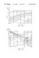
- FIG. 4Bis a plot of light output versus rf current for a cold cathode miniature lamp.
- FIG. 4Cis a plot of relative luminance versus time for the cold cathode miniature lamp of FIG. 4B at five different illustrative currents for a 20,000 hour lamp.
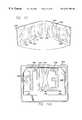
- FIG. 5Ais an exploded perspective view of a preferred embodiment of the optical module of the present invention.
- FIG. 5Bis a perspective view of the assembled module of FIG. 5 A.
- FIG. 5Cis a cross-sectional view of the module of FIG. 5B along line 5 C— 5 C.
- FIG. 5Dis a cross-sectional view of the module of FIG. 5B along line 5 D— 5 D.
- FIG. 5Eis a schematic block diagram showing a first preferred electrical ballast configuration for the optical module of the present invention with battery backup operation.
- FIG. 5Fis a schematic block diagram showing a second preferred electrical ballast configuration with battery backup operation.
- FIG. 6is an illustrative partial side view of an installed optical module of the present invention showing the optical geometry of the installed module.
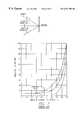
- FIG. 7is a prior art figure of the optical reflectance of light as a function of the angle of incidence.
- FIG. 8Ais a side view showing an illustrative parabolic reflector configuration.
- FIG. 8Bis a side view of an illustrative low profile parabolic reflector with a single lamp.
- FIG. 8Cis a side view of an illustrative low profile parabolic reflector with two lamps.
- FIG. 9is a side view of a preferred lamp and reflector configuration, showing the paths of illustrative light rays.
- FIG. 10is a side view of a second lamp and reflector configuration showing the paths of illustrative light rays.
- FIG. 11is a side view of an illustrative lamp and reflector configuration illustrating the coupling geometry.
- FIG. 12is a side view of a second illustrative lamp and reflector configuration illustrating the coupling geometry.
- FIG. 13is a perspective view showing a display panel in which the indicia include a fluorescent material responsive to near ultra-violet light.
- FIG. 14Ais a front view showing an insertable element containing fluorescent indicia.
- FIG. 14Bshows an indirectly lit fluorescent display.
- FIG. 15is a perspective view of the optical chassis of the optical module shown in FIG. 5 .
- FIG. 16an elevated perspective view of the bottom section of one of the clamps shown in FIG. 5 .
- FIG. 17is a rear perspective view of the clamp section of FIG. 16 .
- FIG. 18is a perspective view of the top section of one of the clamps shown in FIG. 5 .
- FIG. 19is a perspective view of an alternate embodiment of an optical plate for use in the module of FIG. 5 A.
- FIG. 4Ais a top view of a prior art miniature cold cathode fluorescent lamp 400 .
- Miniature cold-cathode fluorescent lampsare low power lamps sometimes used to provide background illumination in laptop computers.
- a variety of models of miniature cold-cathode fluorescent lampscan be obtained from Stanley Electric Co., Ltd. of Nakemeguro, Meguro-ku, Japan.
- Miniature cold cathode lampsrequire a substantial AC voltage, typically several hundred volts, in order to achieve optimal light output.
- the frequency at which a cold cathode lamp is drivenvaries, typically they are operated at a drive current frequency on the order of about 10-50 kHz, with 50 kHz being optimal for many lighting applications.
- Miniature cold cathode lampstypically have an optimum power output at an operating temperature between twenty-five to thirty degrees Celsius.
- Miniature cold-cathode fluorescent lampscome in a range of lengths and diameters.
- the inventordescribes miniature cold-cathode fluorescent lamps with a diameter no greater than about six millimeters as “sub-miniature” lamps, i.e., sub-miniature lamps are a subset of miniature lamps.
- Sub-miniature cold cathode fluorescent lampsare significantly smaller than conventional T-5 fluorescent lamps, which have a diameter of at least 16 mm. Although all miniature cold-cathode fluorescent lamps are fragile, sub-miniature cold-cathode fluorescent lamps are particularly fragile.
- miniature cold cathode fluorescent lampsAlthough the power rating of miniature cold-cathode fluorescent lamps depends upon their length and diameter, a preferred size range of interest for emergency exit signs is a cold cathode lamp with a diameter, D, of between 2.5 and 3.0 millimeters and a length, L, of the body 410 of fluorescent lamp 400 of between 180 to 300 millimeters. Cold cathode fluorescent lamps in this size range draw several watts of power depending upon the operating current and operating voltage. As shown in FIG. 4A, miniature cold cathode lamps are typically sold with one flexible wire lead 420 soldered to each of the two ends 405 of lamp 400 . This is unlike conventional T-5 lamps (not shown in FIG.
- FIG. 4Ashows the light vs current characteristic of a sub-miniature cold cathode fluorescent lamp 400 with a diameter of 2.6 millimeters. It can be seen that there is an operating regime from about 2 mA to 5 mA over which the light output increases almost linearly with drive current. However, the light output tends to increase at a slower rate at higher drive currents and tends to saturate at high drive currents.
- FIG. 4Cshows a plot of relative luminance versus time for the lamp of FIG. 4A.
- a subminiature lamp 400 with characteristics similar to those of FIGS. 4B and 4Cmust typically be operated at a high frequency rms drive current of about 5 mA or less in order to have a reasonable lifetime.
- the total light output, in lumens, of a sub-miniature lamp 400 operated at a drive current consistent with a long lifetimeis approximately one-third that of a conventional T-5 lamp of similar length. This makes it difficult to use a small number of cold cathode fluorescent lamps to replace conventional T-5 lamps while achieving approximately the same light output as conventional T-5 lamps. Moreover, there are other factors which make it difficult to use miniature cold cathode fluorescent lamps to replace T-5 lamps in edge lit signs.
- miniature cold cathode fluorescent lamps 400are much more fragile because of their small diameter; 2) miniature cold cathode fluorescent lamps 400 require non-standard electrical connections to flexible leads 420 ; 3) miniature cold cathode fluorescent lamps 400 have voltage (ballast) requirements which are different from conventional fluorescent lamps; 4) the small diameter of miniature cold cathode fluorescent lamps 400 results in poor optical coupling of light from the lamps in many lighting applications; and 5) the non-standard electrical connections of miniature cold cathode fluorescent lamps means that there is no commercially available mounting means available for the lamps.
- the present inventiongenerally comprises an optical module which facilitates using miniature cold cathode fluorescent lamps as an illumination source in edge lit emergency exit signs and which may conveniently be used to retrofit an existing sign.
- the optical module of the present inventionmay be used for other applications as well.
- the optical module of the present inventionmay be used with other miniature lamps which have a tube shape body 410 and flexible leads 420 similar to that of a miniature cold cathode fluorescent lamp 400 .
- FIG. 5Ais an exploded perspective view of a preferred embodiment of an optical module 500 of the present invention.
- optical module 500is as a substitute for light source 330 in edge lit signs similar to that shown in FIG. 3 . Consequently, it is shaped to be inserted into a specific housing 352 as a direct replacement, or retrofit kit, for one particular style of light source 330 in one style of housing 352 .
- optical module 500may be shaped to fit into different housing shapes and styles as part of a new emergency exit sign, as a replacement kit for other styles of edge-lit sign, or as alternate light source in original equipment manufacturer (OEM) applications.
- OEMoriginal equipment manufacturer
- optical module 500is shown having two lamps 400 it may have any number of lamps, such as one, two, three, or more lamps. Additionally, as discussed below in more detail, optical module 500 is believed to have other applications in addition to emergency exit signs, including a variety of edge-lit display sign applications.
- optical module 500includes an optical chassis 515 to which other components are attached, i.e., chassis 515 is the framework which supports components such as lamps 400 and power supplies which drive the lamps 400 .
- the rear surface 516 of optical chassis 515is preferably shaped as a compartment to hold a ballast compartment 510 containing voltage converters and/or a battery backup power supply configured to convert line voltage (or battery voltage) into a voltage appropriate to power lamps 400 .
- a cover 505is shaped to mate with optical chassis 515 .
- Cover 505has a lip 507 which forms a mechanical coupling surface shaped to engage a groove in a housing (not shown in FIG. 5A) to facilitate insertion and mounting of the optical module in addition to removal of the optical module from the exit sign.
- Optical chassis 515also preferably has spacers 517 arranged to form an air gap between the lip 507 of cover 505 and optical chassis 515 in the assembled module 500 .
- FIG. 5Bis a perspective view of the assembled module 500 .
- a power connector 362is preferably connected to provide AC line power to ballast 510 .
- FIG.is a cross sectional view along line 5 C′— 5 C′ of FIG. 5B, with the housing and panels of an edge lit emergency exit sign shown in phantom.
- FIG. 5Dis a cross-sectional view along line 5 D′— 5 D′ of FIG. 5B, also showing, in phantom, the housing and display panels of an edge lit emergency exit sign.
- lip 507is shaped to slide into a first slot 380 of a housing 352 of an emergency exit sign.
- ballast 510preferably includes a high frequency switch mode power supply to convert AC line voltage into a voltage appropriate for lamp 400 . It is known that switch mode power supplies can be made to be extremely compact and capable of operating at a variety of input voltages or line frequencies. Consequently ballast 510 can be made comparatively compact compared to the power supply, stepdown transformers, and ballast requirements of conventional T-5 lamps. Additionally, ballast 510 preferably is coupled to a battery charging and backup circuit.
- FIGS. 5E and 5Fare electronic block diagrams showing two preferred ballast configurations which include battery charging and low voltage DC backup circuits.
- optical module 500includes several features to support and cushion the fragile miniature cold cathode lamps 400 .
- the ends 405 of each lamp 400are cushioned by resilient sockets 570 .
- Resilient sockets 570are preferably composed of a silicone compound suitable for electrical applications.
- Each socket 570has a receptacle 574 shaped to slide around portion of lamp 400 proximate an end 405 .
- socket 570has a passageway 572 shaped to communicate flexible lead 420 out of socket 570 , i.e., passageway 572 is connected to receptacle 574 in the body of socket 570 . While FIG.
- socket 570may have any suitable shape as long as it has a receptacle 574 shaped to received the end of the lamp and a passageway 572 for communicating lead 420 out of the body of the socket 570 .
- Each resilient socket 570is held in place by a clamp comprising clamp sections 530 and 550 .
- First clamp section 530 and a second clamp section 550are shaped to engage the outer surfaces of sockets 570 forming a lampholder 575 holding one end 405 of lamp 400 .
- Leads 420pass out of lampholder 575 and are coupled to ballast 510 .
- First clamp section 530is preferably shaped to be engagably received by a channel 590 in optical chassis 515 . It can be seen in FIGS. 5A and 5C that second clamp section 550 has hooks shaped to lock with the first clamp section 530 and with the edges of channel 590 .
- the two lampholders 575are dimensioned to support each lamp 410 above the surface of reflector 522 of optical chassis 515 .
- the body 410 of each lamp 400is supported a significant distance above the surface of the reflector, i.e., a distance greater than the diameter of the lamp 400 .
- lamp 400is held 3.7 mm from the surface of the reflector.
- the resilient sockets 570cushion the lamps 400 while the spacing of the lamps 400 from the reflector permits them to flex during transportation, installation, or in the event of mechanical shock and vibration to the assembled exit sign (e.g., during an earthquake). This further reduces the potential for breakage of lamps 400 .
- an optical plate 525such as a transparent plate or a translucent plate, is disposed several millimeters below the lamps 410 .
- optical plate 525does not significantly alter the trajectory of light rays passing through optical plate 525 .
- optical plate 525may also comprise one or more optical elements, such as one or more lens elements, to focus light from module 500 .
- optical plate 525may be curved or shaped to form a lens.
- lamps 400are disposed several millimeters from plate 525 and several millimeters from reflector.
- the assembled module 500lamps 400 are protected by plate 525 , and surfaces 516 , 519 , 523 which form a guard protecting lamps 400 from being accidentally struck. Consequently, the assembled module 500 may be shipped as an assembled unit using ordinary packaging methods. This makes module 500 particularly useful as a retrofit kit, since it can be shipped and installed as an assembled unit.
- optical module 500may be used as a retrofit kit for emergency exit signs 300 similar to that shown in FIG. 3 .
- mechanical coupling surfaces 507may be shaped in a variety of ways and module 500 may also include other types of mechanical couplers, such as bolts, screws, and locking pins. Consequently, the specific design of the optical module may be adapted for insertion in specific existing types of styles of display signs.
- module 500which is coupled into the display panels 110 of an emergency exit sign is significantly greater than that of conventional T-5 lamps.
- the preferred reflector design shown in module 500permits an emergency exit sign with two subminiature lamps 400 with a 6 watt input to produce a total light output at the display surface which is 50% greater than a conventional edge lit sign using two T-5 lamps with an input power of 32 watts for a 277 volt model.
- T-5 lamphas an optical flux of 350 lumens.
- a total light flux of about 108 lumensis coupled from the two lamps into the top entrance surface of the display which corresponds to about 15.5% coupling of light emitted from the lamps into the display panels.
- the lampshave a diameter of 2.6 millimeters, a length of 280 millimeters, and have a flux of 115 lumens each.
- the lampsare spaced apart by about 0.3 inches.
- a total of about 160.5 lumens of fluxis coupled into the entrance of the guides for the preferred embodiment. This corresponds to 45.8% of the total light output of lamps 400 being coupled into the display panels.
- FIGS. 6 - 14Optimized Reflector Design For Improved Illumination And Lifetime
- a miniature or sub-miniature cold cathode fluorescent lamp 400has a maximum light output which is typically much less than that of a T-5 lamp. Moreover, it is desirable to operate lamp 400 at the lowest practical rms current in order to improve the lifetime of lamp 400 . However, a single miniature lamp operated at a current consistent with a long operating lifetime may only have one-half to one-third the total light output of a conventional T-5 lamp, depending upon the diameter of the miniature cold cathode lamp. In order to achieve the greatest energy savings, it is desirable that each T-5 lamp be replaced by one miniature cold cathode fluorescent lamp of about the same length. Consequently, the total optical coupling of each miniature lamp to the display panel should be about a factor of two-to-three higher than that of a conventional T-5 lamp arrangement in order to have a light output from the display panels comparable to a conventional T-5 lamp arrangement.
- a reflectorwhich increases the fraction of light coupled to the display panels, particular if a small number of cold cathode fluorescent lamps 400 are used.
- a compact module 500permits only limited room for a reflector. Additionally, the lamps 400 tend to block a significant fraction of reflected light.
- the inventorhas developed a low profile reflector design that is specifically designed to increase the coupling of light into the display panels for the unique geometry of edge-light displays, such as wedge-shaped displays. This permits a small number of lamps 400 to produce a light output comparable to conventional T-5 lamps.
- FIG. 6is an illustrative side view of an assembled double-sided edge lit sign 600 with a side panel of the housing 352 removed. Some components of module 500 are omitted to illustrate the geometry of the lamps 400 of the present invention in an assembled emergency exit sign 600 .
- Two conventional T-5 lamps 150are shown in phantom to illustrate the optical geometry of the present invention compared with the prior art.
- sign 600has two tapered acrylic panels 354 held by slots 610 in housing 352 . Each panel 354 has the words “EXIT” proximate the outer surface of each panel 354 in accord with conventional practice.
- a reflective layer 605such as a layer of a reflective plastic or mylar, is disposed into a slot between panels 354 to form two tapered light guides 110 which transmit light along the length, L, of each panel. Reflective layer 605 also serves to block the view of the opposed EXIT sign indicia on the opposite side of the panels, thereby improving visibility. Commonly, panels 354 are attached together to form one integral unit. The paths of two illustrative light rays 690 , 692 are shown, in phantom, traversing each light guide 110 . The two light rays are shown entering each waveguide 110 at a different entrance angle such that the rays traverse different paths.
- Light rays which reflect off of the reflector surface 605 and the surface dielectric/air interfacereflect at an angle equal to the angle of incidence.
- an optical ray that enters the waveguide at a shallow anglesuch as ray 692
- experiences fewer reflections than a ray, such as ray 690which enters at a steeper angle.
- the housing 352 of pre-existing edge lit sign 600has a width, W, and height, H.
- the width, Wvaries with design style but is typically less than about four centimeters.
- the height, Halso varies with design style, but is typically less than about five centimeters.
- Two conventional T-5 fluorescent lamps 150are shown in phantom inside housing 352 to illustrate the size constraints of a conventional housing 352 .
- Lamp bi-pins 100provides for mounting and electrical connection to a conventional T-5 socket 170 .
- a conventional T-5 lamp 150has a diameter of about 16 millimeters. Placed side-by-side, two T-5 lamps occupy most of the transverse inner width of housing 352 .
- a PCB (printed circuit board) 160 connected to T-5 lamps bi-in sockets 170is also inserted into groove 380 .
- the T-5 lampsalso occupy a substantial portion of the vertical height of housing 352 below groove 380 .
- the ballast required for two conventional T-5 lampsalso requires a significant volume.
- a slide-in PCB module 160 dimensioned to slide into groove 380 of a standard housing 352 and containing two T-5 lampswill fill almost the entire volume of housing 352 .
- Note that the limited space in housing 352makes it impractical to include a reflector for conventional T-5 lamps. This also leaves relatively no space to incorporate other desirable features, such as a battery compartment to provide emergency power to lamps 150 during a power blackout, or related electrical components.
- the current rough-in section 120must be used to connect housing 352 to ceiling or walls and requires a substantial volume devoted to contain batteries, step down transformers, and ballast assemblies.
- miniature cold cathode lamps 400have a small diameter compared to conventional T-5 lamps.
- the two miniature lamps 400also have a diameter that is much less than the width, W O of entrance surfaces 620 of guides 110 .
- each lamp 400may have a diameter of about 3 millimeters whereas the width W O of the entrance surfaces 620 of guides 110 may have a combined width of between ten to twenty-six millimeters. This is in contrast to conventional T-5 lamps 150 which have a combined width greater than 3.2 centimeters, which is greater than that of the two guides 110 . Referring to FIG.
- the small diameter of lamps 400permits a reflector 522 to be included in a vertical height less than that of a standard T-5 lamp.
- a miniature lamp 400with a diameter of three millimeters. If an annular space three millimeters in differential diameter around the length of lamp 400 is included, the effective diameter of the lamp, including the annular space, is still nine millimeters.
- a low profile reflector 522 with a vertical height of about three millimetersresults in a module with a total vertical height of 12 millimeters, which is less than the diameter of a standard T-5 lamp, thereby facilitating the incorporation of a high voltage ballast and a battery back up circuitry in module 500 .
- lamps 400have a sufficiently small diameter such that a low-profile reflector 522 may be incorporated in module 500 to improve the coupling of light from lamps 400 to panels 110 . Consequently, the optical module of the present invention may be designed to achieve up to about a three-fold improvement in the coupling of light from lamps 400 to panels 354 compared with conventional fluorescent lamps 150 .
- This improved optical coupling of module 500combined with the high light conversion efficiency of cold cathode lamps, results in a more than five-fold improvement in energy efficiency compared to conventional T-5 fluorescent lamps 150 .
- optical module 500consumes about 6 watts of power at a light output from display surfaces 130 that is comparable to a conventional fluorescent illumination source with two T-5 lamps 150 drawing 32 watts of electrical power for 277 volt circuits.
- An optical chassis 515 with a reflector 522 to couple light into display panels in an edge lit emergency exit signposes special optical reflector problems.
- One consideration for an optical chassis 515is that the width of reflector 522 is limited by the width of the optical chassis 515 . Consequently, the reflector will encompass a limited arc angle of the emitted light, i.e, the limited width of the reflector makes it difficult to design a reflector that encompasses more than about 40% of the light emitted from each lamp.
- An additional considerationis that an optical chassis 515 designed to replace an LED module or conventional T-5 lamps is limited to a maximum height governed by the design of the housing. This limits the maximum depth of reflector 522 and guard walls to a height less than or equal to a conventional T-5 lamp.
- FIG. 7is a prior art curve showing the reflection coefficient of light at an air-glass interface as a function of incident angle.
- Curve (a)corresponds to light that is polarized in the plane of incidence.
- Curve (c)corresponds to light that is polarized in a plane perpendicular to the plane of incidence.
- Curve (b)corresponds to nonpolarized light.
- the light emitted from lamps 400can be modeled as nonpolarized, corresponding to curve (b). It can be seen that the reflection increases rapidly for an initial angle of incidence greater than about seventy degrees with respect to normal.
- Reflector 522is thus preferably shaped to reflect a large fraction of light into the entrance of the display panel with an angle of incidence of about seventy degrees or less.
- FIG. 8Ais an illustrative diagram of a reflector configuration which utilizes a conventional parabolic reflector 810 to maximize the fraction of light coupled into a guide 805 .
- the parabolic reflectorhas a width, W, that is many times greater than the diameter, D, of the lamp. As an illustrative example, the width, W, of reflector 810 may be twenty times the diameter of lamp 820 .
- Shadowing of lamp 800can thus be ignored since only a small percentage of the reflected light impinges back onto lamp 820 .
- the height, H, of reflector 810may be selected as required so that the curvature of reflector 810 focuses all of the reflected light back onto the entrance of guide 805 .
- reflector 810will receive 50 percent of the light emitted from lamp 820 .
- lamp 820approximates a line source, which facilitates designing a parabolic reflector that couples a large fraction of the reflected light into the length of the guide 805 .
- FIG. 8Billustrates the problems of conventional parabolic reflectors when there are space constraints.
- the width of the reflectoris only several times the diameter of lamp 820 .
- the height, H, of the reflectoris limited to be about the same as the diameter of the lamp and the total length, L, from reflector 810 to guide 805 is limited to several times the diameter of lamp 820 .
- the limited width of reflector 810 coupled with a limited heightreduces the design freedom.
- FIG. 8Aillustrates a parabolic reflector geometry similar to that of FIG. 8B but with two lamps 820 , 830 . Note that reflected light rays 1 and 2 may be reflected onto the lamp that emitted them or onto the other lamp.
- FIG. 9is an illustrative side view of a first preferred reflector 905 shape similar to what is shown in FIG. 5 . Since reflector 905 is formed as part of an optical chassis, it will be noted that sidewalls 902 are connected to reflector 905 . Sidewalls 902 do not couple reflected light to guide 110 but are part of the mechanical structure of optical chassis 515 and also serve to shield and protect lamps 400 -A and 400 -B. Sidewalls 902 are shown having a slight curvature where they connect with reflector 905 in accord with common plastic injection molding processes. There is a maximum reflector width, W R , and reflector height, h.
- W Ris less than the maximum width of the optical chassis Wc and the height of the reflector, h, is less than the maximum height, hc, of the lamp and reflector portion of the optical chassis.
- a smoothly varying quasi-parabolic reflector surface 950is shown in FIG. 9 in order to discuss several aspects of the shape of reflector 905 which permit it to achieve a higher efficiency than a conventional parabolic reflector with a comparable width and height.
- the width, W D , of display panels 920is shown in FIG. 9 as being less than the maximum reflector width, which is common in edge lit emergency exit display signs.
- the two lamps 400 -A and 400 -Bare spaced apart transversely by a distance S, as in the embodiment shown in FIG. 5 .
- the paths of illustrative reflective light rays 12 , 13 , 14 , 15 , 16are shown for one of the lamps 400 A and 400 B.
- reflector 905is shaped to improve the coupling of light to waveguides 110 .
- the majority of the reflected raysenter the surface 915 of display panels 920 at a comparatively steep angle, i.e., less than or equal to about seventy degrees from normal.
- the surface of reflector 905preferably includes a plurality of segments 990 , 992 , 994 , shaped to more effectively couple reflected light from lamps 400 -A and 400 -B to panel 920 . It can be seen that segments 990 , 992 , and 994 have corresponding tips 995 , 996 , and 997 .
- Segments 990 , 992 , 994are localized regions which are a protuberance in which the curvature of the reflector can deviate substantially from a simple parabolic shape, thereby favorably redirecting light rays which would otherwise exit the reflector or be reflected back onto a lamp 400 .
- a segment 992 of reflector 905is shaped so that a ray 12 strikes segment 992 and enters surface 915 -A of display panel 920 .
- reflector 905is preferably shaped along segment 990 over solid angle ⁇ to reduce the shadowing of lamp 400 .
- the change in slope along segment 990advantageously increases the angle of reflection compared to a smooth parabolic reflector 950 , for which rays 18 and 20 would reflect back onto lamp 400 -A. Consequently, reflector 905 is significantly more efficient at coupling reflected light from lamps 400 -A and 400 -B into guide 110 than is a quasi-parabolic reflector 950 of comparable size. Calculations indicate that segments 990 , 992 , and 994 increase the flux coupled into the guide by at least about 8% compared to a simple parabolic reflector for a lamp with a diameter of less than 3 millimeters.
- FIG. 10shows a single lamp embodiment in which the reflector is shaped to reduce the fraction of reflected light which reflects back onto the lamp and to increase the fraction of light that reflects into the display panel at a comparatively low angle of incidence.
- FIG. 10is an illustrative side view showing a second preferred reflector shape for an embodiment with a single lamp 400 The paths of illustrative reflected rays 8 , 9 , 10 , 11 are shown. Comparing quasi-parabolic comparison line 805 , shown in phantom, it can be seen that the reflector 1005 includes region 1010 which is shaped to reduce deleterious reflections of light rays back onto the lamps that would otherwise occur with a quasi-parabolic reflecting surface 805 (shown in phantom).
- While reflector 905provides a benefit over a wide range of design parameters for optical chassis 515 , the inventor believes that there are ranges of parameters over which the light coupling is optimal. Reducing the diameter of lamps 400 -A and 400 -B facilitates selecting a shape of reflector 905 which reduces shadowing by lamps 400 -A and 400 -B with reflected rays entering the entrance surfaces 915 -A and 915 -B at a low angle of incidence.
- the diameter of each lamp 400is less than or equal to about half the width of the entrance surface of a single light guide.
- FIG. 11illustrates the shadowing geometry.
- a reflector 1010is used to reflect light to guide 1020 .
- Reflector 1010is shown as having a generally parabolic shape for the purposes of illustration although in accord with FIG. 9 localized regions may have a non-parabolic shape.
- the height, hcis held constant, as it would be in an optical chassis used as a replacement kit for standard sized T-5 lamps or LED sources.
- appropriate selection of the diameter of lamp 1090 compared to the width of guide 1020permits rays 1 and 2 to be deflected back into guide 1020 from a tip region 1090 .
- a significantly larger diameter of lamp 1090would result in the body of lamp 1090 blocking rays 1 and 2 , which is undesirable.
- the edges of reflector 1010 at points A and Bare preferably smoothly varying, i.e., quasi parabolic to facilitate a manufacturing process in which they are coupled to chassis walls or shields. Consequently, appropriate selection of the diameter of lamp 1090 permits rays 3 and 4 to be coupled to guide 1020 while relaxing the requirements on the shape of reflector 1010 at end points A and B. All of the reflected rays 1 , 2 , 3 , and 4 preferably have an angle of incident that is fairly steep, i.e., less than or equal to about seventy degrees to achieve a high coupling efficiency of reflected light into guide 1020 . Referring to FIG.
- a minimum diametercan be calculated for lamp 1090 so that rays 1 , 2 , 3 , and 4 enter guide 1020 at some maximum entrance angle (e.g., seventy degrees) without striking lamp 1090 .
- the diameter of lamp 1090is preferably about half the diameter of guide 1020 or less. While FIG. 11 shows a single lamp and a single guide 1020 , a similar result can be obtained for two spaced apart lamps coupled into two guides as shown in FIG. 9 . Additionally, as indicated in FIG. 12 a similar result is obtained even if reflector 1010 is slightly wider than the guide 1020 .
- a conventional cold cathode fluorescent lamp 400contains a gas within the lamp which produces ultraviolet radiation when the gas is excited by the electrical discharge.
- the ultraviolet radiationexcites a phosphor coating disposed on the inner wall of the lamp, with the chemical composition of the phosphor selected so that the phosphor radiates principally white light.
- cold cathode fluorescent lamp 400may be an ultraviolet lamp. As is well known, light with a wavelength of 400 nanometers corresponds to violet, the shortest wavelength of visible light. Near ultraviolet light commonly refers to ultraviolet light with a wavelength between about 200 to 400 nanometers. Cold cathode fluorescent lamps which produce near ultra-violet light are commercially available, such as lamps with an emission wavelength of about 351 or 368 nanometers. The wavelength of a cold cathode fluorescent lamp may be tailored by a variety of methods, such as the use of black light filters or black light glass.
- FIG. 13shows two display panels 1354 with indicia 1356 containing a fluorescent pigment material.
- the fluorescent materialmay be an ink or paint applied to a surface or it may be a material incorporated into a plastic or polymer material.
- a preferred class of fluorescent materialsare fluorescent pigments.
- Fluorescent pigmentsare generally comprised of resinous solutions of dyes. There are commonly used in so-called “day glow” fluorescent plastics to make objects more visible under normal lighting conditions. Fluorescent pigments can be obtained from a variety of vendors, such as the RADIANT® K-600 colorants sold by Radiant Color of Richmond, Calif. Fluorescent pigments, such as those sold by Radiant Color, are commonly sold as pellets or powders that may be incorporated into a variety of colorants for different plastics.
- fluorescent pigmentsmay be incorporated into other materials, such as some types of inks and paints.
- Fluorescent pigmentsalso have a “glowing” fluorescence color which depends upon their composition and the frequency of UV light they are exposed to. They are sold in a variety of fluorescent colors, such as chartreuse, green, orange-yellow, orange, red, cherise, pink, magenta, blue, and purple.
- Fluorescent pigmentsmay be illuminated by a variety of different lamp wavelengths but a lamp wavelength range between about 365 to 380 nanometers is believed by the inventor to be optimal for many applications. However, the optimal ultraviolet lamp wavelength will depend on the optimum input wavelength of the fluorescent pigment for a particular desired color of emitted light.
- Characters and indicia fabricated from a fluorescent materialtend to visually stand out in normal lighting, but glow when exposed to ultraviolet light.
- the inventorhas experimented with adding fluorescent pigments to plastics similar to those commonly used in the illuminated display art.
- conventional day glow plasticsinclude a proportion of fluorescent pigment colorant selected so that plastic is opaque in normal illumination.
- the inventorbelieves that in the UV embodiments of the present invention it is preferable to use a significantly lower proportion of fluorescent pigment colorant so that the plastic is translucent in normal lighting but glows when exposed to ultraviolet light.
- UV light lamp and fluorescent indiciapermits significant improvement in efficiency compared to conventional lighting approaches. This is because conventional lighting systems must convert the ultraviolet light generated in lamp 400 to visible light via a phosphor coating in the lamp, with the resultant white light being filtered by conventional colored indicia. In conventional lighting systems a significant fraction of energy is lost in converting the ultraviolet light from the lamp to visible light and by the filtering process of converting the white light to colored light in conventional colored plastics. In contrast, in the UV embodiments of the present invention an ultraviolet lamp pumps the fluorescent indicia, which directly converts UV light into light of a desired color.
- FIG. 14Ashows an alternate embodiment in which an edgelit replaceable sheet 1430 contains fluorescent indicia 1456 .
- Sheet 1430is shown attached by clips 1380 to the interior of a display panel 1354 .
- sheet 1430could also be implemented instead as an injection molded letter assembly, i.e., as only the letters or indicia instead of an entire planar sheet.
- sheet 1430could also be sandwiched between panels 1354 . It also may be tapered in width to improve the uniformity of illumination of the letters or indicia.
- sheet 1430 and display panels 1354 , 1356are preferably used in an edge lit sign, the inventor has also recognize that they may be used in other ways as well.
- Near ultraviolet lightlight close in wavelength to visible light, is comparatively safe to the human eye, particularly at low intensities and for a wavelength range close to the visible spectrum (e.g., 350 nanometers to 400 nanometers). Consequently, a sheet, such as sheet 1430 , may also be indirectly illuminated by a source of near ultraviolet radiation. For example an external ultraviolet lamp and reflector may be used to illuminate a single sheet 1430 .
- FIG. 14Bshows an embodiment of a display sign 1480 in which the indicia 1485 comprise a plastic having fluorescent colorant.
- the concentration of fluorescent colorantis preferably selected so that the indicia are translucent (or transparent) in normal illumination but glow when exposed to ultraviolet light such as that from a UV light source 1490 .
- UV light source 1490may be a localized indirect light source.
- light source 1490could be mounted, for example, spaced apart from display sign 1480 .
- a reflector 1492is desirable to focus and direct light from UV lamp 1490 onto display sign 1480 .
- FIGS. 15 - 18Preferred Shock Resistant Socket Design
- Miniature cold cathode fluorescent lampsare extremely fragile. During transportation or insertion of an assembled module 500 they may be subjected to substantial vibration or shock. As seen in FIG. 5A resilient sockets 570 and clamp sections, 530 , 550 form lampholders 575 . Resilient sockets 570 help to damp vibration upon lamps 400 and absorb shock. Clamp sections 530 , 570 preferably support lamps 400 several millimeters above the surface of reflector 522 , thereby permitting the body of each lamp to flex in response to mechanical vibration or shock. In a preferred embodiment, the lamps are separated greater than 3.7 millimeters from the reflector, which corresponds to a separation distance slightly greater than the diameter of lamp 400 .
- module 500exclusive of lamps 400 and the electronic components of ballast 510 , is preferably comprised primarily of plastic sections formed by an injection molding process.
- optical chassis 515 , the surface of ballast 510 , cover 505 , and clamp sections 530 , 550are all formed using an injection molding process.
- Reflector 522is also preferably formed from injection molded plastic as one part, but with a reflective coating formed over the surface of reflector 522 .
- a variety of suitable materials to create a reflective coating over a piece of injection molded plasticare well known in the plastic flashlight and sunglass arts. Any conventional reflective coating may be applied using conventional methods to form a reflective coating on the surface of reflector 522 . It will be noted, referring to FIGS. 5 and 15, that reflector 522 is preferably shaped with a substantially uniform material thickness to facilitate an injection molding process.
- clamp sections 530 , 550could have a variety of shapes and mounting configurations, the inventor has developed a low-cost configuration which obviates the need for additional metal connectors or metal screws and which is detachable to facilitate the replacement of lamps 400 .
- plastic engagement surfacessuch as plastic hooks and chamfers, are configured to permit the plastic components of module 500 to snap together without bolts or screws.
- Clamp sections 530 , 550are preferably shaped to distribute forces evenly over the surface of socket 570 . They are also preferably shaped to permit the sections to be quickly decoupled from channel 590 of optical chassis 515 to facilitate insertion and removal of lamp 400 .
- FIGS. 15-18show detailed views of the inner surfaces of clamp sections 530 , 550 .
- FIG. 15is a perspective view, from a different angle than that of FIG. 5, showing channels 590 in optical chassis 515 .
- FIG. 16shows an upper perspective view of first clamp section 530 .
- FIG. 17shows a rear perspective view of first clamp section 530 showing a detail of a channel 1705 for communicating lead wires 420 .
- FIG. 18is a perspective view, from a different angle than that of FIG.
- second clamp section 550along with details of hooks 1805 which lock the clamp sections 530 , 550 in place.
- the plastic comprising second clamp 550is capable of sufficient flexure to permit hooks 1807 to be snapped into place to lock the socket assembly 575 , 580 into place by insertion into channel 590 of chassis 515 .
- FIG. 5Ashows optical plate 525 as a planar sheet.
- optical plate 525could be shaped to have a non planar lens surface 526 or contain optical lens elements to improve the coupling of light to the display panels of an emergency exit sign.
- an optical plate 525 performing a lens functionmay be desirable for use in other applications, such as path lighting, where it may be desirable to adjust the optical output of module 500 , e.g., increase or decrease its divergence.
- optical module 500One of the benefits of optical module 500 is that the lamps 400 tend to operate at a nearly optimum temperature, which improves their efficiency.
- the lamps 400 of the present inventionare supported below the surface of the reflector. Consequently, they will lose very little heat through direct thermal conduction at either end of the lamp held by the lampholder. They are partially isolated from the ambient atmosphere by a thin volume of air trapped by the optical plate such that convection losses will be moderated. Thermal equilibrium is achieved when the net power dissipation of the lamps equals thermal heat flow to the ambient environment.
- Cold cathode fluorescent lampsfunction most efficiently in a temperature range of about 25-30° C., which corresponds to a temperature range for which the operating voltage decreases and the light output increases. Since no heaters are required for the efficient operation of the cold cathode lamps of the present invention, it is believed by the inventor that the thermal properties of the preferred optical module 500 are such that the lamps operate at a temperature between about 25-30° C. (i.e., 5-10° C. higher than room temperature).
- the thermal characteristics of the modulemay also be tailored to improve the light output of emergency signs which flash in an emergency notification mode. Although most emergency exit signs are operated in a continuous mode, signs which flash on and off in emergencies or during power failures are also used in some geographic areas.
- the thermal mass of a cold cathode fluorescent lamp with a diameter less than three millimetersis comparatively low. Consequently, the inventor believes that the thermal time constant required for lamp 400 to increase in temperature by five-to-ten degrees Celsius is a fraction of a second. This makes optical module 500 useful for the efficient illumination of flashed emergency exit signs and/or for flashed displays used in other applications (e.g., advertisement displays).
- optical module 500is particularly adapted for use in emergency exit signs, the invention may have other uses as well.
- Optical module 500is comparatively compact, energy efficient, and resistant to mechanical vibration and shock such that it may be used to replace conventional T-5 lamps in a variety of applications.
- optical module 500could be used to illuminate an advertising display.
- a variety of display signs, such as those used in food stores,have one or more conventional fluorescent lamps disposed inside a plastic housing.
- the reflector surfaces of optical module 500may be shaped to illuminate a variety of display surfaces in addition to edge-lit displays.
- module 500may be used as a battery powered emergency illumination system.
- Optical module 500could, for example, be used to provide emergency path lighting.
- reflector surfaces 521 , 522should be shaped to achieve the desired illumination of a path.
- reflector 522could be shaped to adjust the divergence of the emitted beam and directed to illuminate the ground.
- Optical module 500may also be used with a mounting bracket as an undercounter task light.
- optical module 500could be used as a light source in campers, recreational vehicles, boats, or other applications where a compact, energy efficient light source replacing conventional T-5 lamps is desirable.
Landscapes
- Physics & Mathematics (AREA)
- General Physics & Mathematics (AREA)
- Optics & Photonics (AREA)
- Business, Economics & Management (AREA)
- Accounting & Taxation (AREA)
- Marketing (AREA)
- Engineering & Computer Science (AREA)
- Theoretical Computer Science (AREA)
- Illuminated Signs And Luminous Advertising (AREA)
Abstract
Description
Claims (27)
Priority Applications (1)
| Application Number | Priority Date | Filing Date | Title |
|---|---|---|---|
| US09/476,236US6471388B1 (en) | 1999-12-30 | 1999-12-30 | Illumination apparatus for edge lit signs and display |
Applications Claiming Priority (1)
| Application Number | Priority Date | Filing Date | Title |
|---|---|---|---|
| US09/476,236US6471388B1 (en) | 1999-12-30 | 1999-12-30 | Illumination apparatus for edge lit signs and display |
Publications (1)
| Publication Number | Publication Date |
|---|---|
| US6471388B1true US6471388B1 (en) | 2002-10-29 |
Family
ID=23891059
Family Applications (1)
| Application Number | Title | Priority Date | Filing Date |
|---|---|---|---|
| US09/476,236Expired - LifetimeUS6471388B1 (en) | 1999-12-30 | 1999-12-30 | Illumination apparatus for edge lit signs and display |
Country Status (1)
| Country | Link |
|---|---|
| US (1) | US6471388B1 (en) |
Cited By (94)
| Publication number | Priority date | Publication date | Assignee | Title |
|---|---|---|---|---|
| US20030021122A1 (en)* | 2001-07-30 | 2003-01-30 | Randall Stephen Michael | Illumination device utilizing displaced radiation patterns |
| US20030066220A1 (en)* | 2001-08-18 | 2003-04-10 | Velez Michael A. | Visual display unit |
| US20030067008A1 (en)* | 2000-05-15 | 2003-04-10 | General Electric Company | White light emitting phosphor blend for LED devices |
| US20030192216A1 (en)* | 2002-04-12 | 2003-10-16 | Hsu Ju Sheng | Escape guiding or indicating device |
| US20040041521A1 (en)* | 2002-08-28 | 2004-03-04 | Adaptive Micro Systems, Inc. | Display device with molded light guide |
| US20040055193A1 (en)* | 2002-07-18 | 2004-03-25 | Rolf Broelemann | Backlit sign |
| US6731077B1 (en)* | 2003-04-08 | 2004-05-04 | Hsin-Hui Cheng | Modularized LED illuminator |
| US20040114345A1 (en)* | 2002-12-12 | 2004-06-17 | Dong-Hoon Kim | Light guide plate with stepped edge and display device having the same |
| US20040170015A1 (en)* | 2003-04-25 | 2004-09-02 | Douglas Hamrick | Exit sign illuminated by selective color leds |
| US20040189218A1 (en)* | 2002-11-19 | 2004-09-30 | Leong Susan J. | Led retrofit lamp |
| US20050039361A1 (en)* | 2002-10-08 | 2005-02-24 | Wu Chen H. | Method and apparatus for backlit signs with light emitting diode modules |
| US6870655B1 (en)* | 1998-10-14 | 2005-03-22 | Gentex Corporation | Rearview mirror with display |
| US20050117368A1 (en)* | 2002-04-16 | 2005-06-02 | Samsung Electronics Co., Ltd. | Backlight assembly for liquid crystal display apparatus |
| US20050146898A1 (en)* | 2003-12-30 | 2005-07-07 | Chih-Kang Wu | Support for Backlight Module |
| US20050146893A1 (en)* | 2002-07-26 | 2005-07-07 | Siemens Aktiengesellschaft | Display device comprising a luminous element with an emission characteristic of controllable solid angle |
| US20050162093A1 (en)* | 2000-02-11 | 2005-07-28 | Jos Timmermans | Light tube and power supply circuit |
| US20050185390A1 (en)* | 2004-02-25 | 2005-08-25 | Citizen Electronics Co., Ltd. | Double-faced lighting device |
| US6971758B2 (en)* | 2001-03-16 | 2005-12-06 | Toyoda Gosei Co., Ltd. | Illumination device |
| US20060002135A1 (en)* | 2004-07-01 | 2006-01-05 | Eurodent S.P.A. | Dental lamp particularly for medical and dental surgeries |
| US20060018108A1 (en)* | 2004-07-23 | 2006-01-26 | Thomas & Betts Corporation | Cold-cathode fluorescent lamp assembly for lighting applications |
| US20060077069A1 (en)* | 2004-09-30 | 2006-04-13 | Kontovich Michael S | Multi-function egress path device |
| US20060164827A1 (en)* | 2005-01-27 | 2006-07-27 | Minewiser Hugh T | Portable sign illuminator |
| WO2006062514A3 (en)* | 2004-12-08 | 2006-08-10 | Mack Trucks | Multi-function lamp for a motor vehicle |
| US20070030693A1 (en)* | 2003-04-02 | 2007-02-08 | Dennis Karlsson | Convex luminant sign |
| US7188986B1 (en) | 2006-01-03 | 2007-03-13 | Ronald Paul Harwood | Illuminated sign |
| US7192161B1 (en)* | 2001-10-18 | 2007-03-20 | Ilight Technologies, Inc. | Fluorescent illumination device |
| US20070064172A1 (en)* | 2002-09-26 | 2007-03-22 | Kyu-Seok Kim | Backlight assembly and liquid crystal display device using the same |
| US20070151853A1 (en)* | 2005-12-29 | 2007-07-05 | Invitrogen Corporation | Compositions and Methods for Improving Resolution of Biomolecules Separated on Polyacrylamide Gels |
| US20070189001A1 (en)* | 2002-12-11 | 2007-08-16 | Safeexits, Inc. | Multi-functional ballast and location-specific lighting |
| US20070236941A1 (en)* | 2006-02-14 | 2007-10-11 | Mark Logan | Illuminated sign insert |
| US20070289180A1 (en)* | 2006-05-30 | 2007-12-20 | Jeff Johnson | Light box |
| US20080197790A1 (en)* | 2002-12-11 | 2008-08-21 | Mangiaracina Anthony A | Lighting utilizing power over the ethernet |
| US20080250685A1 (en)* | 2007-04-10 | 2008-10-16 | Thomas & Betts International, Inc. | Illuminated Sign with Single-Point LED Light Source |
| US20080266849A1 (en)* | 2007-04-30 | 2008-10-30 | Nielson Lyman O | Fluorescent lighting conversion to led lighting using a power converter |
| US20090168458A1 (en)* | 2007-12-26 | 2009-07-02 | Foxsemicon Integrated Technology, Inc. | Light-emitting panel and luminaire having same |
| US20100136897A1 (en)* | 2006-09-15 | 2010-06-03 | Bookyu Lee | ventilation cover with a light source |
| US20100141647A1 (en)* | 2008-12-09 | 2010-06-10 | Jong Hag Kim | Back light unit for liquid crystal display device and method for fabricating the same |
| US7845103B2 (en) | 2006-02-14 | 2010-12-07 | Acuity Brands, Inc. | Illuminated sign mounting structure |
| US7926975B2 (en) | 2007-12-21 | 2011-04-19 | Altair Engineering, Inc. | Light distribution using a light emitting diode assembly |
| US7938562B2 (en) | 2008-10-24 | 2011-05-10 | Altair Engineering, Inc. | Lighting including integral communication apparatus |
| US7946729B2 (en) | 2008-07-31 | 2011-05-24 | Altair Engineering, Inc. | Fluorescent tube replacement having longitudinally oriented LEDs |
| US7976196B2 (en) | 2008-07-09 | 2011-07-12 | Altair Engineering, Inc. | Method of forming LED-based light and resulting LED-based light |
| US20110194167A1 (en)* | 2009-07-20 | 2011-08-11 | Jeanette Elisabeth Jackson | Multi-segmented displays |
| US20110232143A1 (en)* | 2007-05-30 | 2011-09-29 | Georgiana Hsu | Exit sign illuminated by color leds |
| US8038315B1 (en)* | 2009-06-05 | 2011-10-18 | Santoro Scott R | Luminaire housing with printed bottom panel |
| USD648469S1 (en) | 2006-03-20 | 2011-11-08 | Thomas & Betts International, Inc. | Combination exit sign and emergency lighting fixture assembly |
| US8093823B1 (en)* | 2000-02-11 | 2012-01-10 | Altair Engineering, Inc. | Light sources incorporating light emitting diodes |
| US8118447B2 (en) | 2007-12-20 | 2012-02-21 | Altair Engineering, Inc. | LED lighting apparatus with swivel connection |
| US8214084B2 (en) | 2008-10-24 | 2012-07-03 | Ilumisys, Inc. | Integration of LED lighting with building controls |
| US8256924B2 (en) | 2008-09-15 | 2012-09-04 | Ilumisys, Inc. | LED-based light having rapidly oscillating LEDs |
| US8299695B2 (en) | 2009-06-02 | 2012-10-30 | Ilumisys, Inc. | Screw-in LED bulb comprising a base having outwardly projecting nodes |
| US20120281151A1 (en)* | 2010-01-29 | 2012-11-08 | Sharp Kabushiki Kaisha | Lighting device, display device and television receiver |
| US8324817B2 (en) | 2008-10-24 | 2012-12-04 | Ilumisys, Inc. | Light and light sensor |
| US8330381B2 (en) | 2009-05-14 | 2012-12-11 | Ilumisys, Inc. | Electronic circuit for DC conversion of fluorescent lighting ballast |
| US8362710B2 (en) | 2009-01-21 | 2013-01-29 | Ilumisys, Inc. | Direct AC-to-DC converter for passive component minimization and universal operation of LED arrays |
| US8360599B2 (en) | 2008-05-23 | 2013-01-29 | Ilumisys, Inc. | Electric shock resistant L.E.D. based light |
| US8421366B2 (en) | 2009-06-23 | 2013-04-16 | Ilumisys, Inc. | Illumination device including LEDs and a switching power control system |
| US8444292B2 (en) | 2008-10-24 | 2013-05-21 | Ilumisys, Inc. | End cap substitute for LED-based tube replacement light |
| US8454193B2 (en) | 2010-07-08 | 2013-06-04 | Ilumisys, Inc. | Independent modules for LED fluorescent light tube replacement |
| US8523394B2 (en) | 2010-10-29 | 2013-09-03 | Ilumisys, Inc. | Mechanisms for reducing risk of shock during installation of light tube |
| US8540401B2 (en) | 2010-03-26 | 2013-09-24 | Ilumisys, Inc. | LED bulb with internal heat dissipating structures |
| US8541958B2 (en) | 2010-03-26 | 2013-09-24 | Ilumisys, Inc. | LED light with thermoelectric generator |
| US8556452B2 (en) | 2009-01-15 | 2013-10-15 | Ilumisys, Inc. | LED lens |
| US8596813B2 (en) | 2010-07-12 | 2013-12-03 | Ilumisys, Inc. | Circuit board mount for LED light tube |
| US8653984B2 (en) | 2008-10-24 | 2014-02-18 | Ilumisys, Inc. | Integration of LED lighting control with emergency notification systems |
| US8664880B2 (en) | 2009-01-21 | 2014-03-04 | Ilumisys, Inc. | Ballast/line detection circuit for fluorescent replacement lamps |
| US8674626B2 (en) | 2008-09-02 | 2014-03-18 | Ilumisys, Inc. | LED lamp failure alerting system |
| US20140118993A1 (en)* | 2012-10-30 | 2014-05-01 | Hon Hai Precision Industry Co., Ltd. | Electronic incense assembly and method for manufacturing electronic incense assembly |
| US20140286051A1 (en)* | 2013-03-21 | 2014-09-25 | Kabushiki Kaisha Tokai Rika Denki Seisakusho | Display device |
| US8870415B2 (en) | 2010-12-09 | 2014-10-28 | Ilumisys, Inc. | LED fluorescent tube replacement light with reduced shock hazard |
| US8901823B2 (en) | 2008-10-24 | 2014-12-02 | Ilumisys, Inc. | Light and light sensor |
| US8984780B2 (en) | 2012-02-06 | 2015-03-24 | GE Lighting Solutions, LLC | Edge-lit light engine module for signs and sign |
| US9057493B2 (en) | 2010-03-26 | 2015-06-16 | Ilumisys, Inc. | LED light tube with dual sided light distribution |
| US9072171B2 (en) | 2011-08-24 | 2015-06-30 | Ilumisys, Inc. | Circuit board mount for LED light |
| US9163794B2 (en) | 2012-07-06 | 2015-10-20 | Ilumisys, Inc. | Power supply assembly for LED-based light tube |
| US9184518B2 (en) | 2012-03-02 | 2015-11-10 | Ilumisys, Inc. | Electrical connector header for an LED-based light |
| USD744040S1 (en) | 2012-08-14 | 2015-11-24 | Ben Schloss | Edge lit magnetic sign |
| US9271367B2 (en) | 2012-07-09 | 2016-02-23 | Ilumisys, Inc. | System and method for controlling operation of an LED-based light |
| US9267650B2 (en) | 2013-10-09 | 2016-02-23 | Ilumisys, Inc. | Lens for an LED-based light |
| US9285084B2 (en) | 2013-03-14 | 2016-03-15 | Ilumisys, Inc. | Diffusers for LED-based lights |
| USD751648S1 (en) | 2013-08-21 | 2016-03-15 | Cooper Technologies Company | Light-emitting diode edge lighted airfield guidance sign |
| US20160109634A1 (en)* | 2014-10-15 | 2016-04-21 | Minebea Co., Ltd. | Spread illuminating apparatus |
| US20160148472A1 (en)* | 2014-11-25 | 2016-05-26 | Denovo Lighting, Llc | Exit sign illuminated by color leds |
| WO2016160285A1 (en)* | 2015-03-31 | 2016-10-06 | General Electric Company | System and method for continuous, asynchronous autofocus of optical instruments |
| US9495892B2 (en) | 2013-08-21 | 2016-11-15 | Cooper Technologies Company | Light-emitting diode edge lighted airfield guidance sign |
| US9510400B2 (en) | 2014-05-13 | 2016-11-29 | Ilumisys, Inc. | User input systems for an LED-based light |
| US9574717B2 (en) | 2014-01-22 | 2017-02-21 | Ilumisys, Inc. | LED-based light with addressed LEDs |
| US9589487B1 (en)* | 2014-12-22 | 2017-03-07 | Cooper Technologies Company | Combined edgelit signage and illumination |
| US20170139109A1 (en)* | 2014-07-03 | 2017-05-18 | Saint-Gobain Glass France | Luminous glazing assembly |
| US10161568B2 (en) | 2015-06-01 | 2018-12-25 | Ilumisys, Inc. | LED-based light with canted outer walls |
| US20190094457A1 (en)* | 2017-09-26 | 2019-03-28 | Radiant Opto-Electronics (Suzhou) Co., Ltd | Lighting device |
| US11519581B2 (en)* | 2016-10-14 | 2022-12-06 | Lumileds Llc | Vehicle light assembly comprising flexible lighting strip |
| US11649959B2 (en)* | 2019-01-22 | 2023-05-16 | Edgy Tools LLC | Lighted wedge tool |
| US20240117963A1 (en)* | 2022-10-05 | 2024-04-11 | David Sherman | Luminaire for use with a mailbox |
Citations (21)
| Publication number | Priority date | Publication date | Assignee | Title |
|---|---|---|---|---|
| US3984931A (en) | 1975-08-28 | 1976-10-12 | Belokin Jr Paul | Illuminated overhead advertising display |
| US4229780A (en) | 1978-06-27 | 1980-10-21 | West Virginia Armature Company | Fluorescent lamp for use in explosive atmospheres such as mines |
| US4385343A (en) | 1978-12-26 | 1983-05-24 | Plumly George W | Edge lighted devices |
| US4435743A (en)* | 1981-06-22 | 1984-03-06 | Plumly George W | Edge lighted sign |
| US4587600A (en) | 1985-04-30 | 1986-05-06 | John Morten | Lighting fixture |
| US4587597A (en) | 1984-11-19 | 1986-05-06 | Meyers Charles J | Emergency exit light or the like |
| US4713019A (en) | 1986-09-17 | 1987-12-15 | Edwin Gaynor | Sockets for compact fluorescent lamps |
| US5122074A (en) | 1990-08-09 | 1992-06-16 | Voltarc Technologies Inc. | Flourescent lamp holder mount |
| US5276591A (en) | 1992-07-23 | 1994-01-04 | William Hegarty | Sign with indirect illumination from light emitting diodes |
| US5370546A (en) | 1993-01-08 | 1994-12-06 | National Cathode Corp. | Lamp holder for cold cathode fluorescent lamp |
| US5390094A (en) | 1994-04-14 | 1995-02-14 | National Cathode Corp. | All-weather cold-cathode lighting assembly |
| US5410454A (en) | 1991-08-29 | 1995-04-25 | Meitaku System Co., Ltd. | Device for supplying incident light to edge light panels |
| US5433024A (en) | 1993-10-04 | 1995-07-18 | Displayonix Corp. | Edge-lighted display |
| US5445540A (en) | 1994-05-31 | 1995-08-29 | Vision Lighting, Inc. | Attachment member for lamp socket and method |
| US5485291A (en) | 1994-02-22 | 1996-01-16 | Precision Lamp, Inc. | Uniformly thin, high efficiency large area lighting panel with two facet grooves that are spaced apart and have light source facing facets with smaller slopes than the facets facing away from the light source |
| US5603627A (en) | 1995-08-22 | 1997-02-18 | National Cathode Corp. | Cold cathode lamp lampholder |
| US5640792A (en) | 1995-06-07 | 1997-06-24 | National Service Industries, Inc. | Lighting fixtures |
| US5727869A (en) | 1996-06-17 | 1998-03-17 | Boyd Lighting Company | Fluorescent light fixture with breakaway socket |
| US5877585A (en) | 1994-10-18 | 1999-03-02 | General Electric Company | Mounting assembly arrangement for a compact fluorescent lamp |
| US5918396A (en)* | 1996-02-16 | 1999-07-06 | Jung; Hae-Ryong | Light box with edge-lit panel |
| US5964515A (en)* | 1996-05-21 | 1999-10-12 | Denso Corporation | Indicating instrument for vehicle |
- 1999
- 1999-12-30USUS09/476,236patent/US6471388B1/ennot_activeExpired - Lifetime
Patent Citations (21)
| Publication number | Priority date | Publication date | Assignee | Title |
|---|---|---|---|---|
| US3984931A (en) | 1975-08-28 | 1976-10-12 | Belokin Jr Paul | Illuminated overhead advertising display |
| US4229780A (en) | 1978-06-27 | 1980-10-21 | West Virginia Armature Company | Fluorescent lamp for use in explosive atmospheres such as mines |
| US4385343A (en) | 1978-12-26 | 1983-05-24 | Plumly George W | Edge lighted devices |
| US4435743A (en)* | 1981-06-22 | 1984-03-06 | Plumly George W | Edge lighted sign |
| US4587597A (en) | 1984-11-19 | 1986-05-06 | Meyers Charles J | Emergency exit light or the like |
| US4587600A (en) | 1985-04-30 | 1986-05-06 | John Morten | Lighting fixture |
| US4713019A (en) | 1986-09-17 | 1987-12-15 | Edwin Gaynor | Sockets for compact fluorescent lamps |
| US5122074A (en) | 1990-08-09 | 1992-06-16 | Voltarc Technologies Inc. | Flourescent lamp holder mount |
| US5410454A (en) | 1991-08-29 | 1995-04-25 | Meitaku System Co., Ltd. | Device for supplying incident light to edge light panels |
| US5276591A (en) | 1992-07-23 | 1994-01-04 | William Hegarty | Sign with indirect illumination from light emitting diodes |
| US5370546A (en) | 1993-01-08 | 1994-12-06 | National Cathode Corp. | Lamp holder for cold cathode fluorescent lamp |
| US5433024A (en) | 1993-10-04 | 1995-07-18 | Displayonix Corp. | Edge-lighted display |
| US5485291A (en) | 1994-02-22 | 1996-01-16 | Precision Lamp, Inc. | Uniformly thin, high efficiency large area lighting panel with two facet grooves that are spaced apart and have light source facing facets with smaller slopes than the facets facing away from the light source |
| US5390094A (en) | 1994-04-14 | 1995-02-14 | National Cathode Corp. | All-weather cold-cathode lighting assembly |
| US5445540A (en) | 1994-05-31 | 1995-08-29 | Vision Lighting, Inc. | Attachment member for lamp socket and method |
| US5877585A (en) | 1994-10-18 | 1999-03-02 | General Electric Company | Mounting assembly arrangement for a compact fluorescent lamp |
| US5640792A (en) | 1995-06-07 | 1997-06-24 | National Service Industries, Inc. | Lighting fixtures |
| US5603627A (en) | 1995-08-22 | 1997-02-18 | National Cathode Corp. | Cold cathode lamp lampholder |
| US5918396A (en)* | 1996-02-16 | 1999-07-06 | Jung; Hae-Ryong | Light box with edge-lit panel |
| US5964515A (en)* | 1996-05-21 | 1999-10-12 | Denso Corporation | Indicating instrument for vehicle |
| US5727869A (en) | 1996-06-17 | 1998-03-17 | Boyd Lighting Company | Fluorescent light fixture with breakaway socket |
Non-Patent Citations (1)
| Title |
|---|
| Hewlett Packard, "Light Guide Techniques Using LED Lamps," "Application Brief I-003," Hewlett-Packard Co., pp. 1-20, (1997). |
Cited By (173)
| Publication number | Priority date | Publication date | Assignee | Title |
|---|---|---|---|---|
| US6870655B1 (en)* | 1998-10-14 | 2005-03-22 | Gentex Corporation | Rearview mirror with display |
| US20050162093A1 (en)* | 2000-02-11 | 2005-07-28 | Jos Timmermans | Light tube and power supply circuit |
| US9006993B1 (en) | 2000-02-11 | 2015-04-14 | Ilumisys, Inc. | Light tube and power supply circuit |
| US9739428B1 (en) | 2000-02-11 | 2017-08-22 | Ilumisys, Inc. | Light tube and power supply circuit |
| US8866396B2 (en) | 2000-02-11 | 2014-10-21 | Ilumisys, Inc. | Light tube and power supply circuit |
| US9746139B2 (en) | 2000-02-11 | 2017-08-29 | Ilumisys, Inc. | Light tube and power supply circuit |
| US8870412B1 (en) | 2000-02-11 | 2014-10-28 | Ilumisys, Inc. | Light tube and power supply circuit |
| US8482212B1 (en) | 2000-02-11 | 2013-07-09 | Ilumisys, Inc. | Light sources incorporating light emitting diodes |
| US10557593B2 (en) | 2000-02-11 | 2020-02-11 | Ilumisys, Inc. | Light tube and power supply circuit |
| US8382327B2 (en) | 2000-02-11 | 2013-02-26 | Ilumisys, Inc. | Light tube and power supply circuit |
| US9006990B1 (en) | 2000-02-11 | 2015-04-14 | Ilumisys, Inc. | Light tube and power supply circuit |
| US9416923B1 (en) | 2000-02-11 | 2016-08-16 | Ilumisys, Inc. | Light tube and power supply circuit |
| US9777893B2 (en) | 2000-02-11 | 2017-10-03 | Ilumisys, Inc. | Light tube and power supply circuit |
| US20110156608A1 (en)* | 2000-02-11 | 2011-06-30 | Altair Engineering, Inc. | Light tube and power supply circuit |
| US9803806B2 (en) | 2000-02-11 | 2017-10-31 | Ilumisys, Inc. | Light tube and power supply circuit |
| US9759392B2 (en) | 2000-02-11 | 2017-09-12 | Ilumisys, Inc. | Light tube and power supply circuit |
| US10054270B2 (en) | 2000-02-11 | 2018-08-21 | Ilumisys, Inc. | Light tube and power supply circuit |
| US8093823B1 (en)* | 2000-02-11 | 2012-01-10 | Altair Engineering, Inc. | Light sources incorporating light emitting diodes |
| US9970601B2 (en) | 2000-02-11 | 2018-05-15 | Ilumisys, Inc. | Light tube and power supply circuit |
| US9752736B2 (en) | 2000-02-11 | 2017-09-05 | Ilumisys, Inc. | Light tube and power supply circuit |
| US9222626B1 (en) | 2000-02-11 | 2015-12-29 | Ilumisys, Inc. | Light tube and power supply circuit |
| US8247985B2 (en) | 2000-02-11 | 2012-08-21 | Ilumisys, Inc. | Light tube and power supply circuit |
| US20030067008A1 (en)* | 2000-05-15 | 2003-04-10 | General Electric Company | White light emitting phosphor blend for LED devices |
| US20060113553A1 (en)* | 2000-05-15 | 2006-06-01 | General Electric Company | White light emitting phosphor blend for led devices |
| US7267785B2 (en) | 2000-05-15 | 2007-09-11 | General Electric Company | White light emitting phosphor blend for LED devices |
| US7015510B2 (en)* | 2000-05-15 | 2006-03-21 | General Electric Company | White light emitting phosphor blend for LED devices |
| US6971758B2 (en)* | 2001-03-16 | 2005-12-06 | Toyoda Gosei Co., Ltd. | Illumination device |
| US20050105880A1 (en)* | 2001-07-30 | 2005-05-19 | 3M Innovative Properties Company | Illumination device utilizing displaced radiation patterns |
| US20030021122A1 (en)* | 2001-07-30 | 2003-01-30 | Randall Stephen Michael | Illumination device utilizing displaced radiation patterns |
| US6957904B2 (en)* | 2001-07-30 | 2005-10-25 | 3M Innovative Properties Company | Illumination device utilizing displaced radiation patterns |
| US20030066220A1 (en)* | 2001-08-18 | 2003-04-10 | Velez Michael A. | Visual display unit |
| US6857212B2 (en)* | 2001-08-18 | 2005-02-22 | Michael Velez | Visual display unit |
| US7192161B1 (en)* | 2001-10-18 | 2007-03-20 | Ilight Technologies, Inc. | Fluorescent illumination device |
| US20030192216A1 (en)* | 2002-04-12 | 2003-10-16 | Hsu Ju Sheng | Escape guiding or indicating device |
| US20050117368A1 (en)* | 2002-04-16 | 2005-06-02 | Samsung Electronics Co., Ltd. | Backlight assembly for liquid crystal display apparatus |
| US7237939B2 (en)* | 2002-04-16 | 2007-07-03 | Samsung Electronics Co., Ltd. | Backlight assembly and liquid crystal display apparatus using the same |
| US20070139966A1 (en)* | 2002-04-16 | 2007-06-21 | Samsung Electronics Co., Ltd., | Backlight assembly for liquid crystal display apparatus |
| US6978566B2 (en)* | 2002-07-18 | 2005-12-27 | Goodrich Hella Aerospace Lighting Systems Gmbh | Backlit sign |
| US20040055193A1 (en)* | 2002-07-18 | 2004-03-25 | Rolf Broelemann | Backlit sign |
| US20050146893A1 (en)* | 2002-07-26 | 2005-07-07 | Siemens Aktiengesellschaft | Display device comprising a luminous element with an emission characteristic of controllable solid angle |
| US7273309B2 (en)* | 2002-07-26 | 2007-09-25 | Siemens Ag | Display device comprising a luminous element with an emission characteristic of controllable solid angle |
| US7084935B2 (en) | 2002-08-28 | 2006-08-01 | Adaptive Micro Systems, Llc | Display device with molded light guide |
| US20060239001A1 (en)* | 2002-08-28 | 2006-10-26 | Adaptive Micro Systems, Llc | Display device with molded light guide |
| US20040041521A1 (en)* | 2002-08-28 | 2004-03-04 | Adaptive Micro Systems, Inc. | Display device with molded light guide |
| US20070064172A1 (en)* | 2002-09-26 | 2007-03-22 | Kyu-Seok Kim | Backlight assembly and liquid crystal display device using the same |
| US7484876B2 (en)* | 2002-09-26 | 2009-02-03 | Samsung Electronics Co., Ltd. | Backlight assembly and liquid crystal display device using the same |
| US20050039361A1 (en)* | 2002-10-08 | 2005-02-24 | Wu Chen H. | Method and apparatus for backlit signs with light emitting diode modules |
| US7303309B2 (en)* | 2002-10-08 | 2007-12-04 | Leotek Electronics Corporation | Method and apparatus for backlit signs with light emitting diode modules |
| US20040189218A1 (en)* | 2002-11-19 | 2004-09-30 | Leong Susan J. | Led retrofit lamp |
| US6853151B2 (en) | 2002-11-19 | 2005-02-08 | Denovo Lighting, Llc | LED retrofit lamp |
| US20070189001A1 (en)* | 2002-12-11 | 2007-08-16 | Safeexits, Inc. | Multi-functional ballast and location-specific lighting |
| US20080197790A1 (en)* | 2002-12-11 | 2008-08-21 | Mangiaracina Anthony A | Lighting utilizing power over the ethernet |
| US20040114345A1 (en)* | 2002-12-12 | 2004-06-17 | Dong-Hoon Kim | Light guide plate with stepped edge and display device having the same |
| US20060232996A1 (en)* | 2002-12-12 | 2006-10-19 | Dong-Hoon Kim | Light guide plate with stepped edge and display device having the same |
| US7077554B2 (en)* | 2002-12-12 | 2006-07-18 | Samsung Electronics Co., Ltd. | Light guide plate with stepped edge and display device having the same |
| US20070030693A1 (en)* | 2003-04-02 | 2007-02-08 | Dennis Karlsson | Convex luminant sign |
| US6731077B1 (en)* | 2003-04-08 | 2004-05-04 | Hsin-Hui Cheng | Modularized LED illuminator |
| US7114840B2 (en)* | 2003-04-25 | 2006-10-03 | Douglas Hamrick | Exit sign illuminated by selective color LEDs |
| US20040170015A1 (en)* | 2003-04-25 | 2004-09-02 | Douglas Hamrick | Exit sign illuminated by selective color leds |
| US20050146898A1 (en)* | 2003-12-30 | 2005-07-07 | Chih-Kang Wu | Support for Backlight Module |
| US6974221B2 (en)* | 2003-12-30 | 2005-12-13 | Au Optronics Corporation | Support for backlight module |
| US20050185390A1 (en)* | 2004-02-25 | 2005-08-25 | Citizen Electronics Co., Ltd. | Double-faced lighting device |
| US20060002135A1 (en)* | 2004-07-01 | 2006-01-05 | Eurodent S.P.A. | Dental lamp particularly for medical and dental surgeries |
| US7226195B2 (en) | 2004-07-23 | 2007-06-05 | Thomas & Betts International | Cold-cathode fluorescent lamp assembly for lighting applications |
| US20060018108A1 (en)* | 2004-07-23 | 2006-01-26 | Thomas & Betts Corporation | Cold-cathode fluorescent lamp assembly for lighting applications |
| US7423548B2 (en)* | 2004-09-30 | 2008-09-09 | Michael Stephen Kontovich | Multi-function egress path device |
| US20060077069A1 (en)* | 2004-09-30 | 2006-04-13 | Kontovich Michael S | Multi-function egress path device |
| WO2006062514A3 (en)* | 2004-12-08 | 2006-08-10 | Mack Trucks | Multi-function lamp for a motor vehicle |
| US20060164827A1 (en)* | 2005-01-27 | 2006-07-27 | Minewiser Hugh T | Portable sign illuminator |
| US9057694B2 (en) | 2005-12-29 | 2015-06-16 | Life Technologies Corporation | Compositions and methods for improving resolution of biomolecules separated on polyacrylamide gels |
| US20070151853A1 (en)* | 2005-12-29 | 2007-07-05 | Invitrogen Corporation | Compositions and Methods for Improving Resolution of Biomolecules Separated on Polyacrylamide Gels |
| US7188986B1 (en) | 2006-01-03 | 2007-03-13 | Ronald Paul Harwood | Illuminated sign |
| US20070236941A1 (en)* | 2006-02-14 | 2007-10-11 | Mark Logan | Illuminated sign insert |
| US7845103B2 (en) | 2006-02-14 | 2010-12-07 | Acuity Brands, Inc. | Illuminated sign mounting structure |
| US7739818B2 (en) | 2006-02-14 | 2010-06-22 | ABL IP Lighting, LLC | Illuminated sign insert |
| USD648469S1 (en) | 2006-03-20 | 2011-11-08 | Thomas & Betts International, Inc. | Combination exit sign and emergency lighting fixture assembly |
| US20070289180A1 (en)* | 2006-05-30 | 2007-12-20 | Jeff Johnson | Light box |
| US20100136897A1 (en)* | 2006-09-15 | 2010-06-03 | Bookyu Lee | ventilation cover with a light source |
| US20080250685A1 (en)* | 2007-04-10 | 2008-10-16 | Thomas & Betts International, Inc. | Illuminated Sign with Single-Point LED Light Source |
| US20080266849A1 (en)* | 2007-04-30 | 2008-10-30 | Nielson Lyman O | Fluorescent lighting conversion to led lighting using a power converter |
| US8911134B2 (en)* | 2007-05-30 | 2014-12-16 | Denovo Lighting, Llc | Exit sign illuminated by color LEDs |
| US20110232143A1 (en)* | 2007-05-30 | 2011-09-29 | Georgiana Hsu | Exit sign illuminated by color leds |
| US8928025B2 (en) | 2007-12-20 | 2015-01-06 | Ilumisys, Inc. | LED lighting apparatus with swivel connection |
| US8118447B2 (en) | 2007-12-20 | 2012-02-21 | Altair Engineering, Inc. | LED lighting apparatus with swivel connection |
| US7926975B2 (en) | 2007-12-21 | 2011-04-19 | Altair Engineering, Inc. | Light distribution using a light emitting diode assembly |
| US20090168458A1 (en)* | 2007-12-26 | 2009-07-02 | Foxsemicon Integrated Technology, Inc. | Light-emitting panel and luminaire having same |
| US8360599B2 (en) | 2008-05-23 | 2013-01-29 | Ilumisys, Inc. | Electric shock resistant L.E.D. based light |
| US8807785B2 (en) | 2008-05-23 | 2014-08-19 | Ilumisys, Inc. | Electric shock resistant L.E.D. based light |
| US7976196B2 (en) | 2008-07-09 | 2011-07-12 | Altair Engineering, Inc. | Method of forming LED-based light and resulting LED-based light |
| US7946729B2 (en) | 2008-07-31 | 2011-05-24 | Altair Engineering, Inc. | Fluorescent tube replacement having longitudinally oriented LEDs |
| US8674626B2 (en) | 2008-09-02 | 2014-03-18 | Ilumisys, Inc. | LED lamp failure alerting system |
| US8256924B2 (en) | 2008-09-15 | 2012-09-04 | Ilumisys, Inc. | LED-based light having rapidly oscillating LEDs |
| US8251544B2 (en) | 2008-10-24 | 2012-08-28 | Ilumisys, Inc. | Lighting including integral communication apparatus |
| US9398661B2 (en) | 2008-10-24 | 2016-07-19 | Ilumisys, Inc. | Light and light sensor |
| US8653984B2 (en) | 2008-10-24 | 2014-02-18 | Ilumisys, Inc. | Integration of LED lighting control with emergency notification systems |
| US10713915B2 (en) | 2008-10-24 | 2020-07-14 | Ilumisys, Inc. | Integration of LED lighting control with emergency notification systems |
| US7938562B2 (en) | 2008-10-24 | 2011-05-10 | Altair Engineering, Inc. | Lighting including integral communication apparatus |
| US10571115B2 (en) | 2008-10-24 | 2020-02-25 | Ilumisys, Inc. | Lighting including integral communication apparatus |
| US10560992B2 (en) | 2008-10-24 | 2020-02-11 | Ilumisys, Inc. | Light and light sensor |
| US10973094B2 (en) | 2008-10-24 | 2021-04-06 | Ilumisys, Inc. | Integration of LED lighting with building controls |
| US11073275B2 (en) | 2008-10-24 | 2021-07-27 | Ilumisys, Inc. | Lighting including integral communication apparatus |
| US11333308B2 (en) | 2008-10-24 | 2022-05-17 | Ilumisys, Inc. | Light and light sensor |
| US10342086B2 (en) | 2008-10-24 | 2019-07-02 | Ilumisys, Inc. | Integration of LED lighting with building controls |
| US8901823B2 (en) | 2008-10-24 | 2014-12-02 | Ilumisys, Inc. | Light and light sensor |
| US8444292B2 (en) | 2008-10-24 | 2013-05-21 | Ilumisys, Inc. | End cap substitute for LED-based tube replacement light |
| US8214084B2 (en) | 2008-10-24 | 2012-07-03 | Ilumisys, Inc. | Integration of LED lighting with building controls |
| US8946996B2 (en) | 2008-10-24 | 2015-02-03 | Ilumisys, Inc. | Light and light sensor |
| US10182480B2 (en) | 2008-10-24 | 2019-01-15 | Ilumisys, Inc. | Light and light sensor |
| US9353939B2 (en) | 2008-10-24 | 2016-05-31 | iLumisys, Inc | Lighting including integral communication apparatus |
| US9585216B2 (en) | 2008-10-24 | 2017-02-28 | Ilumisys, Inc. | Integration of LED lighting with building controls |
| US10176689B2 (en) | 2008-10-24 | 2019-01-08 | Ilumisys, Inc. | Integration of led lighting control with emergency notification systems |
| US8324817B2 (en) | 2008-10-24 | 2012-12-04 | Ilumisys, Inc. | Light and light sensor |
| US9635727B2 (en) | 2008-10-24 | 2017-04-25 | Ilumisys, Inc. | Light and light sensor |
| US10036549B2 (en) | 2008-10-24 | 2018-07-31 | Ilumisys, Inc. | Lighting including integral communication apparatus |
| US9101026B2 (en) | 2008-10-24 | 2015-08-04 | Ilumisys, Inc. | Integration of LED lighting with building controls |
| US10932339B2 (en) | 2008-10-24 | 2021-02-23 | Ilumisys, Inc. | Light and light sensor |
| US20100141647A1 (en)* | 2008-12-09 | 2010-06-10 | Jong Hag Kim | Back light unit for liquid crystal display device and method for fabricating the same |
| US8547373B2 (en)* | 2008-12-09 | 2013-10-01 | Lg Display Co., Ltd. | Back light unit for liquid crystal display device and method for fabricating the same |
| US8556452B2 (en) | 2009-01-15 | 2013-10-15 | Ilumisys, Inc. | LED lens |
| US8362710B2 (en) | 2009-01-21 | 2013-01-29 | Ilumisys, Inc. | Direct AC-to-DC converter for passive component minimization and universal operation of LED arrays |
| US8664880B2 (en) | 2009-01-21 | 2014-03-04 | Ilumisys, Inc. | Ballast/line detection circuit for fluorescent replacement lamps |
| US8330381B2 (en) | 2009-05-14 | 2012-12-11 | Ilumisys, Inc. | Electronic circuit for DC conversion of fluorescent lighting ballast |
| US8299695B2 (en) | 2009-06-02 | 2012-10-30 | Ilumisys, Inc. | Screw-in LED bulb comprising a base having outwardly projecting nodes |
| US8038315B1 (en)* | 2009-06-05 | 2011-10-18 | Santoro Scott R | Luminaire housing with printed bottom panel |
| US8421366B2 (en) | 2009-06-23 | 2013-04-16 | Ilumisys, Inc. | Illumination device including LEDs and a switching power control system |
| US20110194167A1 (en)* | 2009-07-20 | 2011-08-11 | Jeanette Elisabeth Jackson | Multi-segmented displays |
| US20120281151A1 (en)* | 2010-01-29 | 2012-11-08 | Sharp Kabushiki Kaisha | Lighting device, display device and television receiver |
| US8540401B2 (en) | 2010-03-26 | 2013-09-24 | Ilumisys, Inc. | LED bulb with internal heat dissipating structures |
| US9013119B2 (en) | 2010-03-26 | 2015-04-21 | Ilumisys, Inc. | LED light with thermoelectric generator |
| US9057493B2 (en) | 2010-03-26 | 2015-06-16 | Ilumisys, Inc. | LED light tube with dual sided light distribution |
| US8541958B2 (en) | 2010-03-26 | 2013-09-24 | Ilumisys, Inc. | LED light with thermoelectric generator |
| US8840282B2 (en) | 2010-03-26 | 2014-09-23 | Ilumisys, Inc. | LED bulb with internal heat dissipating structures |
| US9395075B2 (en) | 2010-03-26 | 2016-07-19 | Ilumisys, Inc. | LED bulb for incandescent bulb replacement with internal heat dissipating structures |
| US8454193B2 (en) | 2010-07-08 | 2013-06-04 | Ilumisys, Inc. | Independent modules for LED fluorescent light tube replacement |
| US8596813B2 (en) | 2010-07-12 | 2013-12-03 | Ilumisys, Inc. | Circuit board mount for LED light tube |
| US8523394B2 (en) | 2010-10-29 | 2013-09-03 | Ilumisys, Inc. | Mechanisms for reducing risk of shock during installation of light tube |
| US8894430B2 (en) | 2010-10-29 | 2014-11-25 | Ilumisys, Inc. | Mechanisms for reducing risk of shock during installation of light tube |
| US8870415B2 (en) | 2010-12-09 | 2014-10-28 | Ilumisys, Inc. | LED fluorescent tube replacement light with reduced shock hazard |
| US9072171B2 (en) | 2011-08-24 | 2015-06-30 | Ilumisys, Inc. | Circuit board mount for LED light |
| US8984780B2 (en) | 2012-02-06 | 2015-03-24 | GE Lighting Solutions, LLC | Edge-lit light engine module for signs and sign |
| US9184518B2 (en) | 2012-03-02 | 2015-11-10 | Ilumisys, Inc. | Electrical connector header for an LED-based light |
| US9163794B2 (en) | 2012-07-06 | 2015-10-20 | Ilumisys, Inc. | Power supply assembly for LED-based light tube |
| US9807842B2 (en) | 2012-07-09 | 2017-10-31 | Ilumisys, Inc. | System and method for controlling operation of an LED-based light |
| US9271367B2 (en) | 2012-07-09 | 2016-02-23 | Ilumisys, Inc. | System and method for controlling operation of an LED-based light |
| US10278247B2 (en) | 2012-07-09 | 2019-04-30 | Ilumisys, Inc. | System and method for controlling operation of an LED-based light |
| US10966295B2 (en) | 2012-07-09 | 2021-03-30 | Ilumisys, Inc. | System and method for controlling operation of an LED-based light |
| USD744040S1 (en) | 2012-08-14 | 2015-11-24 | Ben Schloss | Edge lit magnetic sign |
| US20140118993A1 (en)* | 2012-10-30 | 2014-05-01 | Hon Hai Precision Industry Co., Ltd. | Electronic incense assembly and method for manufacturing electronic incense assembly |
| US9285084B2 (en) | 2013-03-14 | 2016-03-15 | Ilumisys, Inc. | Diffusers for LED-based lights |
| US20140286051A1 (en)* | 2013-03-21 | 2014-09-25 | Kabushiki Kaisha Tokai Rika Denki Seisakusho | Display device |
| USD751648S1 (en) | 2013-08-21 | 2016-03-15 | Cooper Technologies Company | Light-emitting diode edge lighted airfield guidance sign |
| US9495892B2 (en) | 2013-08-21 | 2016-11-15 | Cooper Technologies Company | Light-emitting diode edge lighted airfield guidance sign |
| US9267650B2 (en) | 2013-10-09 | 2016-02-23 | Ilumisys, Inc. | Lens for an LED-based light |
| US9574717B2 (en) | 2014-01-22 | 2017-02-21 | Ilumisys, Inc. | LED-based light with addressed LEDs |
| US10260686B2 (en) | 2014-01-22 | 2019-04-16 | Ilumisys, Inc. | LED-based light with addressed LEDs |
| US9510400B2 (en) | 2014-05-13 | 2016-11-29 | Ilumisys, Inc. | User input systems for an LED-based light |
| US9864125B2 (en)* | 2014-07-03 | 2018-01-09 | Saint-Gobain Glass France | Illuminated light guide assembly |
| US20170139109A1 (en)* | 2014-07-03 | 2017-05-18 | Saint-Gobain Glass France | Luminous glazing assembly |
| US20160109634A1 (en)* | 2014-10-15 | 2016-04-21 | Minebea Co., Ltd. | Spread illuminating apparatus |
| US9915772B2 (en)* | 2014-10-15 | 2018-03-13 | Minebea Co., Ltd. | Display back illumination apparatus having compression molded light guide |
| US20160148472A1 (en)* | 2014-11-25 | 2016-05-26 | Denovo Lighting, Llc | Exit sign illuminated by color leds |
| US9589487B1 (en)* | 2014-12-22 | 2017-03-07 | Cooper Technologies Company | Combined edgelit signage and illumination |
| US9921399B2 (en) | 2015-03-31 | 2018-03-20 | General Electric Company | System and method for continuous, asynchronous autofocus of optical instruments |
| WO2016160285A1 (en)* | 2015-03-31 | 2016-10-06 | General Electric Company | System and method for continuous, asynchronous autofocus of optical instruments |
| US10161568B2 (en) | 2015-06-01 | 2018-12-25 | Ilumisys, Inc. | LED-based light with canted outer walls |
| US10690296B2 (en) | 2015-06-01 | 2020-06-23 | Ilumisys, Inc. | LED-based light with canted outer walls |
| US11028972B2 (en) | 2015-06-01 | 2021-06-08 | Ilumisys, Inc. | LED-based light with canted outer walls |
| US11428370B2 (en) | 2015-06-01 | 2022-08-30 | Ilumisys, Inc. | LED-based light with canted outer walls |
| US11519581B2 (en)* | 2016-10-14 | 2022-12-06 | Lumileds Llc | Vehicle light assembly comprising flexible lighting strip |
| US10663650B2 (en)* | 2017-09-26 | 2020-05-26 | Radiant Opto-Electronics (Suzhou) Co., Ltd | Lighting device |
| US20190094457A1 (en)* | 2017-09-26 | 2019-03-28 | Radiant Opto-Electronics (Suzhou) Co., Ltd | Lighting device |
| US11649959B2 (en)* | 2019-01-22 | 2023-05-16 | Edgy Tools LLC | Lighted wedge tool |
| US20240117963A1 (en)* | 2022-10-05 | 2024-04-11 | David Sherman | Luminaire for use with a mailbox |
Similar Documents
| Publication | Publication Date | Title |
|---|---|---|
| US6471388B1 (en) | Illumination apparatus for edge lit signs and display | |
| US7357528B2 (en) | CCFL illuminated device and method of use | |
| US6616310B1 (en) | CCFL illuminated device | |
| CN101641550B (en) | Light-emitting diode (LED)-based lighting systems | |
| KR100798680B1 (en) | Light emitting means using light emitting diode | |
| JP3114280U (en) | LED wall plate night light | |
| CN101469844B (en) | Illuminating apparatus | |
| US20090261706A1 (en) | LED Replacement Light Tube for Fluorescent Light Fixture | |
| CN101730820A (en) | Lighting method and system | |
| CN101655189A (en) | Hollow liquid cooling LED bar-shaped lamp | |
| JPWO2007032187A1 (en) | LED illumination light source and LED stand that automatically turns on at power failure | |
| JP3157514U (en) | Double sided LED lighting device | |
| CA2686181A1 (en) | Led light group lamp | |
| WO2006065049A1 (en) | Luminous window/door apparatus using light guide panel | |
| KR200430853Y1 (en) | LED light frame | |
| US7226195B2 (en) | Cold-cathode fluorescent lamp assembly for lighting applications | |
| KR20100003457A (en) | Led lamp substitutable for fluorescent lamp and lighting apparatus having the same | |
| KR100673863B1 (en) | Information display device | |
| US20060209569A1 (en) | Soft glow nightlight | |
| CA2614873C (en) | Cold-cathode fluorescent lamp assembly for lighting applications | |
| CN222210108U (en) | LED illumination flat lamp | |
| JP5507577B2 (en) | Lighting device | |
| KR200244860Y1 (en) | Lighting equipment | |
| KR200368450Y1 (en) | Lighting device for decoration | |
| KR200247202Y1 (en) | Slimshap of signboard |
Legal Events
| Date | Code | Title | Description |
|---|---|---|---|
| AS | Assignment | Owner name:RE-ENERGY, CALIFORNIA Free format text:ASSIGNMENT OF ASSIGNORS INTEREST;ASSIGNOR:MARSH, BRENT;REEL/FRAME:010486/0361 Effective date:19991229 | |
| AS | Assignment | Owner name:BJI ENERGY SOLUTIONS, LLC, CALIFORNIA Free format text:ASSIGNMENT OF ASSIGNORS INTEREST;ASSIGNOR:RE-ENERGY, INC.;REEL/FRAME:012454/0570 Effective date:20011031 | |
| STCF | Information on status: patent grant | Free format text:PATENTED CASE | |
| AS | Assignment | Owner name:SUNPARK ELECTRONCS CORP., CALIFORNIA Free format text:SECURITY AGREEMENT;ASSIGNOR:BJI ENERGY SOLUTIONS, LLC;REEL/FRAME:016226/0819 Effective date:20050131 | |
| AS | Assignment | Owner name:BJI ENERGY SOLUTIONS, LLC, NEW YORK Free format text:RELEASE OF SECURITY INTEREST;ASSIGNOR:SUNPARK ELECTRONICS CORP.;REEL/FRAME:017555/0235 Effective date:20060205 | |
| FPAY | Fee payment | Year of fee payment:4 | |
| FPAY | Fee payment | Year of fee payment:8 | |
| REMI | Maintenance fee reminder mailed | ||
| FPAY | Fee payment | Year of fee payment:12 | |
| SULP | Surcharge for late payment | Year of fee payment:11 |