US6471218B1 - Vehicle suspensions - Google Patents
Vehicle suspensionsDownload PDFInfo
- Publication number
- US6471218B1 US6471218B1US09/763,382US76338201AUS6471218B1US 6471218 B1US6471218 B1US 6471218B1US 76338201 AUS76338201 AUS 76338201AUS 6471218 B1US6471218 B1US 6471218B1
- Authority
- US
- United States
- Prior art keywords
- vehicle
- actuator
- wheels
- sensor
- wheel
- Prior art date
- Legal status (The legal status is an assumption and is not a legal conclusion. Google has not performed a legal analysis and makes no representation as to the accuracy of the status listed.)
- Expired - Lifetime
Links
- 239000000725suspensionSubstances0.000titleclaimsdescription19
- 230000001133accelerationEffects0.000claimsdescription32
- 230000001419dependent effectEffects0.000claims2
- 238000001514detection methodMethods0.000claims1
- 230000000694effectsEffects0.000description3
- 230000006835compressionEffects0.000description1
- 238000007906compressionMethods0.000description1
- 230000007423decreaseEffects0.000description1
- 230000003247decreasing effectEffects0.000description1
Images


Classifications
- B—PERFORMING OPERATIONS; TRANSPORTING
- B60—VEHICLES IN GENERAL
- B60G—VEHICLE SUSPENSION ARRANGEMENTS
- B60G17/00—Resilient suspensions having means for adjusting the spring or vibration-damper characteristics, for regulating the distance between a supporting surface and a sprung part of vehicle or for locking suspension during use to meet varying vehicular or surface conditions, e.g. due to speed or load
- B60G17/015—Resilient suspensions having means for adjusting the spring or vibration-damper characteristics, for regulating the distance between a supporting surface and a sprung part of vehicle or for locking suspension during use to meet varying vehicular or surface conditions, e.g. due to speed or load the regulating means comprising electric or electronic elements
- B60G17/0195—Resilient suspensions having means for adjusting the spring or vibration-damper characteristics, for regulating the distance between a supporting surface and a sprung part of vehicle or for locking suspension during use to meet varying vehicular or surface conditions, e.g. due to speed or load the regulating means comprising electric or electronic elements characterised by the regulation being combined with other vehicle control systems
- B—PERFORMING OPERATIONS; TRANSPORTING
- B60—VEHICLES IN GENERAL
- B60G—VEHICLE SUSPENSION ARRANGEMENTS
- B60G17/00—Resilient suspensions having means for adjusting the spring or vibration-damper characteristics, for regulating the distance between a supporting surface and a sprung part of vehicle or for locking suspension during use to meet varying vehicular or surface conditions, e.g. due to speed or load
- B60G17/015—Resilient suspensions having means for adjusting the spring or vibration-damper characteristics, for regulating the distance between a supporting surface and a sprung part of vehicle or for locking suspension during use to meet varying vehicular or surface conditions, e.g. due to speed or load the regulating means comprising electric or electronic elements
- B60G17/016—Resilient suspensions having means for adjusting the spring or vibration-damper characteristics, for regulating the distance between a supporting surface and a sprung part of vehicle or for locking suspension during use to meet varying vehicular or surface conditions, e.g. due to speed or load the regulating means comprising electric or electronic elements characterised by their responsiveness, when the vehicle is travelling, to specific motion, a specific condition, or driver input
- B60G17/0162—Resilient suspensions having means for adjusting the spring or vibration-damper characteristics, for regulating the distance between a supporting surface and a sprung part of vehicle or for locking suspension during use to meet varying vehicular or surface conditions, e.g. due to speed or load the regulating means comprising electric or electronic elements characterised by their responsiveness, when the vehicle is travelling, to specific motion, a specific condition, or driver input mainly during a motion involving steering operation, e.g. cornering, overtaking
- B—PERFORMING OPERATIONS; TRANSPORTING
- B60—VEHICLES IN GENERAL
- B60G—VEHICLE SUSPENSION ARRANGEMENTS
- B60G21/00—Interconnection systems for two or more resiliently-suspended wheels, e.g. for stabilising a vehicle body with respect to acceleration, deceleration or centrifugal forces
- B60G21/02—Interconnection systems for two or more resiliently-suspended wheels, e.g. for stabilising a vehicle body with respect to acceleration, deceleration or centrifugal forces permanently interconnected
- B60G21/04—Interconnection systems for two or more resiliently-suspended wheels, e.g. for stabilising a vehicle body with respect to acceleration, deceleration or centrifugal forces permanently interconnected mechanically
- B60G21/05—Interconnection systems for two or more resiliently-suspended wheels, e.g. for stabilising a vehicle body with respect to acceleration, deceleration or centrifugal forces permanently interconnected mechanically between wheels on the same axle but on different sides of the vehicle, i.e. the left and right wheel suspensions being interconnected
- B60G21/055—Stabiliser bars
- B60G21/0551—Mounting means therefor
- B60G21/0553—Mounting means therefor adjustable
- B60G21/0555—Mounting means therefor adjustable including an actuator inducing vehicle roll
- B—PERFORMING OPERATIONS; TRANSPORTING
- B60—VEHICLES IN GENERAL
- B60G—VEHICLE SUSPENSION ARRANGEMENTS
- B60G2202/00—Indexing codes relating to the type of spring, damper or actuator
- B60G2202/10—Type of spring
- B60G2202/13—Torsion spring
- B60G2202/135—Stabiliser bar and/or tube
- B—PERFORMING OPERATIONS; TRANSPORTING
- B60—VEHICLES IN GENERAL
- B60G—VEHICLE SUSPENSION ARRANGEMENTS
- B60G2202/00—Indexing codes relating to the type of spring, damper or actuator
- B60G2202/40—Type of actuator
- B60G2202/41—Fluid actuator
- B60G2202/413—Hydraulic actuator
- B—PERFORMING OPERATIONS; TRANSPORTING
- B60—VEHICLES IN GENERAL
- B60G—VEHICLE SUSPENSION ARRANGEMENTS
- B60G2400/00—Indexing codes relating to detected, measured or calculated conditions or factors
- B60G2400/10—Acceleration; Deceleration
- B60G2400/104—Acceleration; Deceleration lateral or transversal with regard to vehicle
- B—PERFORMING OPERATIONS; TRANSPORTING
- B60—VEHICLES IN GENERAL
- B60G—VEHICLE SUSPENSION ARRANGEMENTS
- B60G2400/00—Indexing codes relating to detected, measured or calculated conditions or factors
- B60G2400/60—Load
- B60G2400/61—Load distribution
- B—PERFORMING OPERATIONS; TRANSPORTING
- B60—VEHICLES IN GENERAL
- B60G—VEHICLE SUSPENSION ARRANGEMENTS
- B60G2400/00—Indexing codes relating to detected, measured or calculated conditions or factors
- B60G2400/90—Other conditions or factors
- B60G2400/91—Frequency
- B—PERFORMING OPERATIONS; TRANSPORTING
- B60—VEHICLES IN GENERAL
- B60G—VEHICLE SUSPENSION ARRANGEMENTS
- B60G2500/00—Indexing codes relating to the regulated action or device
- B60G2500/20—Spring action or springs
- B—PERFORMING OPERATIONS; TRANSPORTING
- B60—VEHICLES IN GENERAL
- B60G—VEHICLE SUSPENSION ARRANGEMENTS
- B60G2600/00—Indexing codes relating to particular elements, systems or processes used on suspension systems or suspension control systems
- B60G2600/02—Retarders, delaying means, dead zones, threshold values, cut-off frequency, timer interruption
- B—PERFORMING OPERATIONS; TRANSPORTING
- B60—VEHICLES IN GENERAL
- B60G—VEHICLE SUSPENSION ARRANGEMENTS
- B60G2800/00—Indexing codes relating to the type of movement or to the condition of the vehicle and to the end result to be achieved by the control action
- B60G2800/18—Starting, accelerating
- B60G2800/182—Traction
- B—PERFORMING OPERATIONS; TRANSPORTING
- B60—VEHICLES IN GENERAL
- B60G—VEHICLE SUSPENSION ARRANGEMENTS
- B60G2800/00—Indexing codes relating to the type of movement or to the condition of the vehicle and to the end result to be achieved by the control action
- B60G2800/21—Traction, slip, skid or slide control
- B60G2800/212—Transversal; Side-slip during cornering
- B—PERFORMING OPERATIONS; TRANSPORTING
- B60—VEHICLES IN GENERAL
- B60G—VEHICLE SUSPENSION ARRANGEMENTS
- B60G2800/00—Indexing codes relating to the type of movement or to the condition of the vehicle and to the end result to be achieved by the control action
- B60G2800/21—Traction, slip, skid or slide control
- B60G2800/214—Traction, slip, skid or slide control by varying the load distribution
- B—PERFORMING OPERATIONS; TRANSPORTING
- B60—VEHICLES IN GENERAL
- B60G—VEHICLE SUSPENSION ARRANGEMENTS
- B60G2800/00—Indexing codes relating to the type of movement or to the condition of the vehicle and to the end result to be achieved by the control action
- B60G2800/22—Braking, stopping
- B—PERFORMING OPERATIONS; TRANSPORTING
- B60—VEHICLES IN GENERAL
- B60G—VEHICLE SUSPENSION ARRANGEMENTS
- B60G2800/00—Indexing codes relating to the type of movement or to the condition of the vehicle and to the end result to be achieved by the control action
- B60G2800/24—Steering, cornering
- B60G2800/244—Oversteer
- B—PERFORMING OPERATIONS; TRANSPORTING
- B60—VEHICLES IN GENERAL
- B60G—VEHICLE SUSPENSION ARRANGEMENTS
- B60G2800/00—Indexing codes relating to the type of movement or to the condition of the vehicle and to the end result to be achieved by the control action
- B60G2800/90—System Controller type
- B60G2800/91—Suspension Control
- B—PERFORMING OPERATIONS; TRANSPORTING
- B60—VEHICLES IN GENERAL
- B60G—VEHICLE SUSPENSION ARRANGEMENTS
- B60G2800/00—Indexing codes relating to the type of movement or to the condition of the vehicle and to the end result to be achieved by the control action
- B60G2800/90—System Controller type
- B60G2800/93—Skid or slide control [ASR]
Definitions
- the present inventionrelates to the use of vehicle suspension systems so as to control the steering characteristics of the vehicle.
- the present inventionaims to provide a system in which these problems can be reduced by controlling more accurately the level of traction or grip between the front and rear wheels and the ground during corning.
- the present inventionprovides a vehicle suspension system comprising an actuator arranged to produce an actuator force between a sprung part of the vehicle and a part of the suspension which can move relative to said sprung part thereby to allow vertical travel of a wheel, measuring means arranged to measure cornering of the vehicle, and control means, characterized in that the control means is arranged, in the event of predetermined cornering conditions, to promote lateral slipping of the wheel by producing a rapid variation in said actuator force so as to produce a pulsing of the contact force between the wheel and the ground causing a reduction in adhesion of the wheel, so as to control the steering characteristics of the vehicle.
- the pulsed variationmay be arranged to promote lateral slipping of the front wheels of the vehicle during cornering thereby reducing over-steer. Conversely it could be arranged to promote lateral slipping of the rear wheels of the vehicle during cornering thereby reducing under-steer.
- the measuring meansis arranged to measure lateral acceleration of the vehicle
- the control meansis arranged to control the actuator force in response to the measured lateral acceleration
- control meansis arranged to produce a sharp change in actuator force when the measured lateral acceleration reaches a predetermined level such that a change in lateral acceleration of the vehicle produces a pulse in the actuator force. This will induce vertical vibration of the relevant wheel mounted on said suspension system relative to the sprung part of the vehicle at its natural frequency.
- control meansis arranged to produce pulsed variations in the actuator force of a controlled frequency in the event of said predetermined cornering conditions. This will produce vibration of the relevant wheel at that controlled frequency.
- the actuatormay comprises a strut arranged to produce forces in a vertical direction between a wheel of the vehicle and a sprung part of the vehicle, as in a fully active gas suspension system, for example.
- the actuatormay be arranged to urge two wheels of the vehicle in opposite vertical directions, as in an active roll-control system.
- FIG. 1is a diagrammatic representation of a vehicle including a suspension system according to the invention
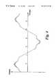
- FIG. 2is a graph showing the relationship between actuator torque and lateral acceleration produced in the system of FIG. 1,
- FIG. 3is a graph corresponding to FIG. 2 for a second embodiment of the invention.
- FIG. 4is a graph showing variation with time of the actuator force in the system of FIG. 1 during cornering
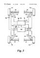
- FIG. 5is a diagrammatic representation of a suspension system according to a third embodiment of the invention.
- a vehiclehas two steerable front wheels 10 , 12 mounted on suspension arms 14 , 16 which are pivotably mounted on the vehicle body at their inner ends to allow vertical movement of the wheels 10 , 12 relative to the vehicle body.
- Two non-steerable rear wheels 18 , 20are similarly mounted on corresponding suspension arms 22 , 24 at the rear of the vehicle.
- the front suspension arms 14 , 16are interconnected by an anti-roll torsion bar 26 which resiliently opposes relative vertical movement of the two front wheels 10 , 12 .
- the torsion bar 26forms part of an assembly including a hydraulic actuator 28 which is only shown schematically and can be operated to apply a torque between the two ends of the torsion bar 26 thereby tending to move the two front wheels 10 , 12 in opposite vertical directions relative to the vehicle body.
- the actuatorcan take a variety of forms which are known, such as a hydraulic strut acting between the end of the torsion bar and the body, or a torsional actuator in the central lateral part of the torsion bar applying a torque between the two ends.
- a corresponding anti-roll bar 30 with an associated actuator 32acts between the rear suspension arms 22 , 24 to control articulation of the rear wheels 18 , 20 .
- the actuators 28 , 32are controlled by a hydraulic control valve block 34 which can connect them up in known manner to a hydraulic pump 36 and reservoir 38 so as to apply torque in either direction independently to each anti-roll bar 26 , 30 .
- the valve block 34is controlled by an electronic control unit 40 , which receives signals from a pair of lateral accelerometers 42 , 44 mounted on the vehicle body which measure the acceleration of the vehicle body in the lateral direction, i.e. the horizontal direction perpendicular to the normal direction of travel at separate points on the vehicle body.
- the control unit 40is arranged to apply an equal torque to the front and rear anti-roll bar actuators 28 , 32 which varies with lateral acceleration of the vehicle as shown by the solid line.
- the applied torqueincreases steadily with lateral acceleration up to about 0.4 g (where g is normal gravitational acceleration). Between 0.4 and 0.75 g the torque increases more gradually. Then between 0.75 and 0.775 g the torque increases rapidly and then levels off forming a sharp discontinuity or step in the torque/lateral acceleration characteristic. Above 0.775 g the torque increases steadily and then levels off towards the maximum torque available from the system.
- the characteristicwould be approximately as shown in the broken line in FIG. 2, i.e. a smooth curve, the shape of which would depend on the amount of body roll desired under varying degrees of lateral acceleration.
- the effect of the step in the characteristicis to reduce over-steer as will now be described.
- the vehicle for which this system would be suitablewould be one which tends to over-steer when the lateral acceleration produced by cornering exceeds about 0.8 g.
- the over-steeris caused by the rear wheels losing grip so that the rear of the vehicle swings outwards on the corner.
- FIG. 2when the lateral acceleration reaches 0.7-0.75 g, the sudden change in torque applied to the anti-roll bars sets up a vertical vibration in the wheels at their natural frequency of vibration, which is accommodated by expansion and compression of the tire and produces a cyclical variation in the contact force between the tire and the ground. This vibration tends to cause both the front and rear wheels to break away at the same time. This tends to prevent over-steer, and will generally result in a certain degree of under-steer, which is usually more acceptable.
- a second embodiment of the inventionuses the same arrangement as shown in FIG. 1, but with a different torque characteristic for the actuators 28 , 32 , which is shown in FIG. 3 .
- This characteristiccomprises a mean torque component which increases in a generally smooth and continuous manner with lateral acceleration, and a pulsed component superimposed on the mean torque component.
- the mean torque curveincreases steadily at a rate sufficient to keep the vehicle approximately level up to a lateral acceleration of about 0.5 g. It then increases more gradually up to about 0.7 g to allow increasing body roll. Then from about 0.7 g it increases more rapidly again towards the maximum torque available to resist high levels of body roll at high lateral accelerations.
- the torque pulses in this exampleare at a frequency of 5 Hz and start at lateral accelerations of 0.7 g. They increase in magnitude up to about 10% of the total torque available and remain at that level for lateral accelerations above 0.775 g.
- FIG. 4The result of this characteristic on the system of FIG. 1 during a slalom type manoeuvre is shown in FIG. 4 .
- the slalom manoeuvrecomprises a series of turns performed at a constant vehicle speed with each pair of opposite turns taking approximately 11 seconds.
- the levelling torque applied to the actuators 28 , 32is increased steadily according to the characteristic of FIG. 3 .
- the torque pulsesstart to come in, superimposed on a continuing rise of the mean torque with increasing lateral acceleration.
- This pulsingcauses the front wheels to break away at about the same time as the rear wheels and therefore prevents over-steer at the tightest point of the turn.
- the pulsingceases and the torque decreases steadily with lateral acceleration.
- the control unitcan be arranged to pulse the torque applied to the front actuator only. This will tend to help the front wheels to break away at the same time as the rear ones without simultaneously reducing the grip of the rear wheels.
- the magnitude and frequency of the pulseswill clearly need to be tuned to suit any particular vehicle. Generally increasing the magnitude and decreasing the frequency will tend to promote lateral slipping, but will tend to increase vibration of the vehicle body. If this vibration reaches a level which can be felt by the driver or passengers, an undesirable reduction of ride quality will result. There is therefore a certain degree of compromise between the performance of the system and ride quality.
- a vehiclehas a fully active independent air suspension, each of the two front wheels 110 , 112 and the two rear wheels 118 , 120 being mounted on a suspension arm 114 , 116 , 122 , 124 which pivots about its inboard end.
- the vertical movement of each wheelis controlled by a gas strut 126 , 128 , 130 , 132 , the gas struts being connectable via a valve block 134 to a pneumatic pump 136 and to atmosphere.
- the valve block 134is controlled by an electronic control unit 140 which controls the pneumatic pressure supplied to each of the gas struts 126 , 128 , 130 , 132 in response to signals from various sensors.
- lateral accelerometers 142 , 143which measure the lateral acceleration at different points of the vehicle body
- height sensors 146which measure the height of each of the wheels 110 , 112 , 118 , 120 relative to the vehicle body
- steering angle sensor 148for measuring the steering angle of the front wheels
- road speed sensors 150only one of which is shown, which measure the road speed of each of the wheels 110 , 112 , 118 , 120 , and hence allow the control unit to determine the road speed of the vehicle.
- the control unit 140includes a map which determines what pressure is supplied to each of the gas struts 126 , 128 , 130 , 132 in response to the full range of possible inputs from the sensors 142 , 143 , 146 , 148 , 150 .
- This controlincludes the usual functions to control pitch and roll of the vehicle and to keep the vehicle level under various loads. However, it also includes a function which allows the pressure supplied to the gas struts 126 , 128 , 130 , 132 to be pulsed when certain conditions are detected. The conditions will vary depending on the characteristics of the vehicle to which the system is applied. However, in this particular embodiment there is a minimum vehicle speed below which no pulsing.
- under- and over-steergenerally do not occur at low speeds.
- pulsingwill be provided to the rear wheels so as to reduce under-steer when the vehicle is cornering so as to produce lateral accelerations above a certain limit, about 0.7 g if the vehicle is similar to that of the second embodiment.
- This lateral accelerationis measured by the lateral accelerometers 142 , 143 , and confirmed as being due to cornering by the steering angle sensor 148 and vehicle speed sensor 150 .
- the systemis arranged to respond rapidly to conditions which are likely to produce particularly severe over-steer, in particular deceleration of the vehicle during cornering which throws weight forward onto the front, steered wheels and therefore tends to increase over-steer.
- the vehicle speed and steering angleindicate that the vehicle is cornering and the wheel speeds and engine speed, which can also be measured, indicate that the driver has lifted his foot off the accelerator and the vehicle starts to decelerate, pulsing of the pressure to the front gas struts can be introduced rapidly before the body has pitched forwards and the over-steer effects become excessive.
- the effect of the system in the third embodimentis essentially the same as in the first and second embodiments, and is to prevent over-steer.
- this inventionit would be possible to use this invention to help overcome the problem by causing vertical vibration of the rear wheels to cause them to break away during cornering. Depending on the characteristics of the vehicle it might be sufficient to vibrate all of the wheels, or it might be necessary to vibrate just the rear wheels.
Landscapes
- Engineering & Computer Science (AREA)
- Mechanical Engineering (AREA)
- Automation & Control Theory (AREA)
- Vehicle Body Suspensions (AREA)
Abstract
Description
Claims (18)
Applications Claiming Priority (3)
| Application Number | Priority Date | Filing Date | Title |
|---|---|---|---|
| GBGB9818268.6AGB9818268D0 (en) | 1998-08-22 | 1998-08-22 | Vehicle suspensions |
| GB9818268 | 1998-08-22 | ||
| PCT/GB1999/002638WO2000010823A1 (en) | 1998-08-22 | 1999-08-10 | Vehicle suspensions |
Publications (1)
| Publication Number | Publication Date |
|---|---|
| US6471218B1true US6471218B1 (en) | 2002-10-29 |
Family
ID=10837629
Family Applications (1)
| Application Number | Title | Priority Date | Filing Date |
|---|---|---|---|
| US09/763,382Expired - LifetimeUS6471218B1 (en) | 1998-08-22 | 1999-08-10 | Vehicle suspensions |
Country Status (6)
| Country | Link |
|---|---|
| US (1) | US6471218B1 (en) |
| EP (1) | EP1104357B1 (en) |
| AU (1) | AU5378499A (en) |
| DE (1) | DE69908784T2 (en) |
| GB (1) | GB9818268D0 (en) |
| WO (1) | WO2000010823A1 (en) |
Cited By (25)
| Publication number | Priority date | Publication date | Assignee | Title |
|---|---|---|---|---|
| US20050216154A1 (en)* | 2004-03-23 | 2005-09-29 | Lehmann Kurt S | Active rollover protection |
| US20050216146A1 (en)* | 2004-03-23 | 2005-09-29 | Continental Teves, Inc. | Body state estimation of a vehicle |
| US20050222727A1 (en)* | 2004-04-02 | 2005-10-06 | Continental Teves, Inc. | Active rollover protection utilizing steering angle rate map |
| US20060122758A1 (en)* | 2004-12-08 | 2006-06-08 | Bauer Geoffrey B | Reduced order parameter identification for vehicle rollover control system |
| WO2006081984A1 (en)* | 2005-02-01 | 2006-08-10 | Bayerische Motoren Werke Aktiengesellschaft | Driving dynamics control or regulating system for a two track, two axle motor vehicle |
| US7096103B2 (en) | 2002-08-05 | 2006-08-22 | Ford Motor Company | System and method for operating a rollover control system during an elevated condition |
| US20060190143A1 (en)* | 2005-02-22 | 2006-08-24 | Continental Teves, Inc. | System to measure wheel liftoff |
| US7120528B2 (en) | 2002-08-05 | 2006-10-10 | Ford Global Technologies, Llc | System and method for operating a rollover control system in a transition to a rollover condition |
| US7130735B2 (en) | 1999-12-21 | 2006-10-31 | Ford Global Technologies, Llc | Roll over stability control for an automotive vehicle |
| US7136730B2 (en) | 2001-11-21 | 2006-11-14 | Ford Global Technologies, Llc | Enhanced system for yaw stability control system to include roll stability control function |
| US7239949B2 (en) | 2003-02-26 | 2007-07-03 | Ford Global Technologies, Llc | Integrated sensing system |
| US20080091317A1 (en)* | 2006-10-17 | 2008-04-17 | Trw Automotive U.S. Llc | Method of controlling a roll control system for improved vehicle dynamic control |
| USRE40268E1 (en) | 2000-09-25 | 2008-04-29 | Ford Global Technologies, Llc | Wheel lift identification for an automotive vehicle |
| US7451032B2 (en) | 2004-06-02 | 2008-11-11 | Ford Global Technologies, Llc | System and method for determining desired yaw rate and lateral velocity for use in a vehicle dynamic control system |
| US7480547B2 (en) | 2005-04-14 | 2009-01-20 | Ford Global Technologies, Llc | Attitude sensing system for an automotive vehicle relative to the road |
| US7590481B2 (en) | 2005-09-19 | 2009-09-15 | Ford Global Technologies, Llc | Integrated vehicle control system using dynamically determined vehicle conditions |
| US7600826B2 (en) | 2005-11-09 | 2009-10-13 | Ford Global Technologies, Llc | System for dynamically determining axle loadings of a moving vehicle using integrated sensing system and its application in vehicle dynamics controls |
| US7640081B2 (en) | 2004-10-01 | 2009-12-29 | Ford Global Technologies, Llc | Roll stability control using four-wheel drive |
| US7660654B2 (en) | 2004-12-13 | 2010-02-09 | Ford Global Technologies, Llc | System for dynamically determining vehicle rear/trunk loading for use in a vehicle control system |
| US7668645B2 (en) | 2004-10-15 | 2010-02-23 | Ford Global Technologies | System and method for dynamically determining vehicle loading and vertical loading distance for use in a vehicle dynamic control system |
| US7715965B2 (en) | 2004-10-15 | 2010-05-11 | Ford Global Technologies | System and method for qualitatively determining vehicle loading conditions |
| US8121758B2 (en) | 2005-11-09 | 2012-02-21 | Ford Global Technologies | System for determining torque and tire forces using integrated sensing system |
| GB2601349A (en)* | 2020-11-27 | 2022-06-01 | Jaguar Land Rover Ltd | Wheel-to-surface contact patch force variation |
| US20240270314A1 (en)* | 2020-03-27 | 2024-08-15 | Polaris Industries Inc. | Utility vehicle |
| US20240408926A1 (en)* | 2023-06-12 | 2024-12-12 | Honda Motor Co., Ltd. | Control device and control method for damping force variable damper |
Families Citing this family (1)
| Publication number | Priority date | Publication date | Assignee | Title |
|---|---|---|---|---|
| US6397127B1 (en)* | 2000-09-25 | 2002-05-28 | Ford Global Technologies, Inc. | Steering actuated wheel lift identification for an automotive vehicle |
Citations (13)
| Publication number | Priority date | Publication date | Assignee | Title |
|---|---|---|---|---|
| EP0106697A1 (en) | 1982-10-18 | 1984-04-25 | Mazda Motor Corporation | Vehicle suspension system |
| US4650212A (en)* | 1985-03-20 | 1987-03-17 | Mazda Motor Corporation | Vehicle suspension system |
| US4821606A (en) | 1986-08-13 | 1989-04-18 | Daimler-Benz Aktiengesellschaft | Arrangement for automatically shifting vehicle aggregates of a motor vehicle |
| DE3817540A1 (en) | 1988-05-24 | 1989-11-30 | Rehm Michael Dipl Ing | Motor vehicle active safety chassis |
| US4903983A (en) | 1986-05-23 | 1990-02-27 | Nissan Motor Company, Limited | Actively controlled automotive suspension system with improved cornering characteristics |
| EP0364965A2 (en) | 1988-10-18 | 1990-04-25 | Nissan Motor Co., Ltd. | Active suspension system for an automotive vehicle with slip angle dependent control for enhanced steering characteristics |
| EP0378202A2 (en) | 1989-01-10 | 1990-07-18 | Nissan Motor Co., Ltd. | Suspension control system for automotive vehicle with adjustment of wheel slippage dependent wheel load distribution |
| US4974875A (en) | 1988-12-29 | 1990-12-04 | Nissan Motor Company, Ltd. | Device for controlling drift of vehicle during cornering |
| US5029892A (en) | 1989-03-31 | 1991-07-09 | Aisin Seiki Kabushiki Kaisha | Hydraulic suspension control device |
| US5033573A (en) | 1989-09-05 | 1991-07-23 | Ford Motor Company | Wheel slip control utilizing active suspension |
| US5517414A (en) | 1994-10-03 | 1996-05-14 | Ford Motor Company | Traction control system with active suspension |
| US5662356A (en) | 1995-04-26 | 1997-09-02 | Tlc Suspension | Roll correction system with countersteer compensation |
| US5711024A (en) | 1994-11-25 | 1998-01-20 | Itt Automotive Europe Gmbh | System for controlling yaw moment based on an estimated coefficient of friction |
- 1998
- 1998-08-22GBGBGB9818268.6Apatent/GB9818268D0/ennot_activeCeased
- 1999
- 1999-08-10WOPCT/GB1999/002638patent/WO2000010823A1/enactiveIP Right Grant
- 1999-08-10AUAU53784/99Apatent/AU5378499A/ennot_activeAbandoned
- 1999-08-10DEDE69908784Tpatent/DE69908784T2/ennot_activeExpired - Lifetime
- 1999-08-10EPEP99939513Apatent/EP1104357B1/ennot_activeExpired - Lifetime
- 1999-08-10USUS09/763,382patent/US6471218B1/ennot_activeExpired - Lifetime
Patent Citations (13)
| Publication number | Priority date | Publication date | Assignee | Title |
|---|---|---|---|---|
| EP0106697A1 (en) | 1982-10-18 | 1984-04-25 | Mazda Motor Corporation | Vehicle suspension system |
| US4650212A (en)* | 1985-03-20 | 1987-03-17 | Mazda Motor Corporation | Vehicle suspension system |
| US4903983A (en) | 1986-05-23 | 1990-02-27 | Nissan Motor Company, Limited | Actively controlled automotive suspension system with improved cornering characteristics |
| US4821606A (en) | 1986-08-13 | 1989-04-18 | Daimler-Benz Aktiengesellschaft | Arrangement for automatically shifting vehicle aggregates of a motor vehicle |
| DE3817540A1 (en) | 1988-05-24 | 1989-11-30 | Rehm Michael Dipl Ing | Motor vehicle active safety chassis |
| EP0364965A2 (en) | 1988-10-18 | 1990-04-25 | Nissan Motor Co., Ltd. | Active suspension system for an automotive vehicle with slip angle dependent control for enhanced steering characteristics |
| US4974875A (en) | 1988-12-29 | 1990-12-04 | Nissan Motor Company, Ltd. | Device for controlling drift of vehicle during cornering |
| EP0378202A2 (en) | 1989-01-10 | 1990-07-18 | Nissan Motor Co., Ltd. | Suspension control system for automotive vehicle with adjustment of wheel slippage dependent wheel load distribution |
| US5029892A (en) | 1989-03-31 | 1991-07-09 | Aisin Seiki Kabushiki Kaisha | Hydraulic suspension control device |
| US5033573A (en) | 1989-09-05 | 1991-07-23 | Ford Motor Company | Wheel slip control utilizing active suspension |
| US5517414A (en) | 1994-10-03 | 1996-05-14 | Ford Motor Company | Traction control system with active suspension |
| US5711024A (en) | 1994-11-25 | 1998-01-20 | Itt Automotive Europe Gmbh | System for controlling yaw moment based on an estimated coefficient of friction |
| US5662356A (en) | 1995-04-26 | 1997-09-02 | Tlc Suspension | Roll correction system with countersteer compensation |
Cited By (51)
| Publication number | Priority date | Publication date | Assignee | Title |
|---|---|---|---|---|
| US7130735B2 (en) | 1999-12-21 | 2006-10-31 | Ford Global Technologies, Llc | Roll over stability control for an automotive vehicle |
| USRE40268E1 (en) | 2000-09-25 | 2008-04-29 | Ford Global Technologies, Llc | Wheel lift identification for an automotive vehicle |
| US7136730B2 (en) | 2001-11-21 | 2006-11-14 | Ford Global Technologies, Llc | Enhanced system for yaw stability control system to include roll stability control function |
| US7096103B2 (en) | 2002-08-05 | 2006-08-22 | Ford Motor Company | System and method for operating a rollover control system during an elevated condition |
| US7120528B2 (en) | 2002-08-05 | 2006-10-10 | Ford Global Technologies, Llc | System and method for operating a rollover control system in a transition to a rollover condition |
| US7239949B2 (en) | 2003-02-26 | 2007-07-03 | Ford Global Technologies, Llc | Integrated sensing system |
| US20050216146A1 (en)* | 2004-03-23 | 2005-09-29 | Continental Teves, Inc. | Body state estimation of a vehicle |
| US7031816B2 (en) | 2004-03-23 | 2006-04-18 | Continental Teves, Inc. | Active rollover protection |
| US7831354B2 (en) | 2004-03-23 | 2010-11-09 | Continental Teves, Inc. | Body state estimation of a vehicle |
| US20050216154A1 (en)* | 2004-03-23 | 2005-09-29 | Lehmann Kurt S | Active rollover protection |
| US20050222727A1 (en)* | 2004-04-02 | 2005-10-06 | Continental Teves, Inc. | Active rollover protection utilizing steering angle rate map |
| US7369927B2 (en) | 2004-04-02 | 2008-05-06 | Continental Teves, Inc. | Active rollover protection utilizing steering angle rate map |
| US7451032B2 (en) | 2004-06-02 | 2008-11-11 | Ford Global Technologies, Llc | System and method for determining desired yaw rate and lateral velocity for use in a vehicle dynamic control system |
| US7640081B2 (en) | 2004-10-01 | 2009-12-29 | Ford Global Technologies, Llc | Roll stability control using four-wheel drive |
| US7899594B2 (en) | 2004-10-15 | 2011-03-01 | Ford Global Technologies | System and method for qualitatively determining vehicle loading conditions |
| US7877199B2 (en) | 2004-10-15 | 2011-01-25 | Ford Global Technologies | System and method for dynamically determining vehicle loading and vertical loading distance for use in a vehicle dynamic control system |
| US8050857B2 (en) | 2004-10-15 | 2011-11-01 | Ford Global Technologies | System and method for dynamically determining vehicle loading and vertical loading distance for use in a vehicle dynamic control system |
| US7877201B2 (en) | 2004-10-15 | 2011-01-25 | Ford Global Technologies | System and method for dynamically determining vehicle loading and vertical loading distance for use in a vehicle dynamic control system |
| US7877200B2 (en) | 2004-10-15 | 2011-01-25 | Ford Global Technologies | System and method for dynamically determining vehicle loading and vertical loading distance for use in a vehicle dynamic control system |
| US7877178B2 (en) | 2004-10-15 | 2011-01-25 | Ford Global Technologies | System and method for dynamically determining vehicle loading and vertical loading distance for use in a vehicle dynamic control system |
| US7715965B2 (en) | 2004-10-15 | 2010-05-11 | Ford Global Technologies | System and method for qualitatively determining vehicle loading conditions |
| US7668645B2 (en) | 2004-10-15 | 2010-02-23 | Ford Global Technologies | System and method for dynamically determining vehicle loading and vertical loading distance for use in a vehicle dynamic control system |
| US7239952B2 (en) | 2004-12-08 | 2007-07-03 | Continental Teves, Inc. | Reduced order parameter identification for vehicle rollover control system |
| US20060122758A1 (en)* | 2004-12-08 | 2006-06-08 | Bauer Geoffrey B | Reduced order parameter identification for vehicle rollover control system |
| US8005596B2 (en) | 2004-12-13 | 2011-08-23 | Ford Global Technologies | System for dynamically determining vehicle rear/trunk loading for use in a vehicle control system |
| US8219282B2 (en) | 2004-12-13 | 2012-07-10 | Ford Global Technologies | System for dynamically determining vehicle rear/trunk loading for use in a vehicle control system |
| US7660654B2 (en) | 2004-12-13 | 2010-02-09 | Ford Global Technologies, Llc | System for dynamically determining vehicle rear/trunk loading for use in a vehicle control system |
| US8346433B2 (en) | 2004-12-13 | 2013-01-01 | Ford Global Technologies | System for dynamically determining vehicle rear/trunk loading for use in a vehicle control system |
| WO2006081984A1 (en)* | 2005-02-01 | 2006-08-10 | Bayerische Motoren Werke Aktiengesellschaft | Driving dynamics control or regulating system for a two track, two axle motor vehicle |
| US7480553B2 (en) | 2005-02-01 | 2009-01-20 | Bayerische Motoren Werke Aktiengesellschaft | Driving dynamic control or regulating system and method for a two-track, two-axle motor vehicle |
| US20070271018A1 (en)* | 2005-02-01 | 2007-11-22 | Bayerische Motoren Werke Aktiengesellschaft | Driving dynamic control or regulating system and method for a two-track, two-axle motor vehicle |
| US7557697B2 (en) | 2005-02-22 | 2009-07-07 | Continental Teves, Inc. | System to measure wheel liftoff |
| US20060190143A1 (en)* | 2005-02-22 | 2006-08-24 | Continental Teves, Inc. | System to measure wheel liftoff |
| US7480547B2 (en) | 2005-04-14 | 2009-01-20 | Ford Global Technologies, Llc | Attitude sensing system for an automotive vehicle relative to the road |
| US8442720B2 (en) | 2005-09-19 | 2013-05-14 | Ford Global Technologies | Integrated vehicle control system using dynamically determined vehicle conditions |
| US7590481B2 (en) | 2005-09-19 | 2009-09-15 | Ford Global Technologies, Llc | Integrated vehicle control system using dynamically determined vehicle conditions |
| US8352143B2 (en) | 2005-09-19 | 2013-01-08 | Ford Global Technologies | Integrated vehicle control system using dynamically determined vehicle conditions |
| US8311706B2 (en) | 2005-09-19 | 2012-11-13 | Ford Global Technologies | Integrated vehicle control system using dynamically determined vehicle conditions |
| US8346452B2 (en) | 2005-09-19 | 2013-01-01 | Ford Global Technologies | Integrated vehicle control system using dynamically determined vehicle conditions |
| US8005592B2 (en) | 2005-11-09 | 2011-08-23 | Ford Global Technologies | System for dynamically determining axle loadings of a moving vehicle using integrated sensing system and its application in vehicle dynamics controls |
| US7600826B2 (en) | 2005-11-09 | 2009-10-13 | Ford Global Technologies, Llc | System for dynamically determining axle loadings of a moving vehicle using integrated sensing system and its application in vehicle dynamics controls |
| US8121758B2 (en) | 2005-11-09 | 2012-02-21 | Ford Global Technologies | System for determining torque and tire forces using integrated sensing system |
| US7493199B2 (en)* | 2006-10-17 | 2009-02-17 | Trw Automotive U.S. Llc | Method of controlling a roll control system for improved vehicle dynamic control |
| US20080091317A1 (en)* | 2006-10-17 | 2008-04-17 | Trw Automotive U.S. Llc | Method of controlling a roll control system for improved vehicle dynamic control |
| WO2008048569A3 (en)* | 2006-10-17 | 2008-10-09 | Trw Automotive Us Llc | Method of controlling a roll control system for improved vehicle dynamic control |
| US20240270314A1 (en)* | 2020-03-27 | 2024-08-15 | Polaris Industries Inc. | Utility vehicle |
| GB2601349A (en)* | 2020-11-27 | 2022-06-01 | Jaguar Land Rover Ltd | Wheel-to-surface contact patch force variation |
| GB2601349B (en)* | 2020-11-27 | 2023-05-24 | Jaguar Land Rover Ltd | Wheel-to-surface contact patch force variation |
| US12384219B2 (en) | 2020-11-27 | 2025-08-12 | Jaguar Land Rover Limited | Wheel-to-surface contact patch force variation |
| US20240408926A1 (en)* | 2023-06-12 | 2024-12-12 | Honda Motor Co., Ltd. | Control device and control method for damping force variable damper |
| US12344062B2 (en)* | 2023-06-12 | 2025-07-01 | Honda Motor Co., Ltd. | Control device and control method for damping force variable damper |
Also Published As
| Publication number | Publication date |
|---|---|
| GB9818268D0 (en) | 1998-10-14 |
| EP1104357A1 (en) | 2001-06-06 |
| DE69908784T2 (en) | 2004-05-13 |
| WO2000010823A1 (en) | 2000-03-02 |
| DE69908784D1 (en) | 2003-07-17 |
| AU5378499A (en) | 2000-03-14 |
| EP1104357B1 (en) | 2003-06-11 |
Similar Documents
| Publication | Publication Date | Title |
|---|---|---|
| US6471218B1 (en) | Vehicle suspensions | |
| EP1124701B1 (en) | Vehicle suspensions | |
| US6654674B2 (en) | Enhanced system for yaw stability control system to include roll stability control function | |
| US7832738B2 (en) | Method for operating active stabilizers in motor vehicles and motor vehicle having active stabilizers | |
| US5089966A (en) | Actively controlled automotive suspension system with improved damping characteristics | |
| EP0492782B1 (en) | Automotive apparatus and method for dynamically determining the centripetal force of a vehicle | |
| US20020109310A1 (en) | Vehicle stability system using active tilting mechanism | |
| US20070124051A1 (en) | Vehicle drive control system and method | |
| US6688612B1 (en) | Vehicle suspensions | |
| GB2425189A (en) | Method and system of controlling a vehicle system | |
| JPH0585369B2 (en) | ||
| JP2002114140A (en) | Vehicular rolling behavior control system | |
| JP2007508185A (en) | Vehicle suspension control device | |
| US5228719A (en) | Automotive active suspension system for anti-rolling control | |
| JPH06247126A (en) | System for closed and/or open loop control of car chassis | |
| JPH0240522B2 (en) | ||
| US6439582B1 (en) | Vehicle suspensions | |
| KR100837234B1 (en) | ESP, CDC and ABCs integrated control apparatus and method of a vehicle | |
| JP3052995B2 (en) | Suspension control device | |
| JPS63232014A (en) | Vehicle suspension control device | |
| JP3814056B2 (en) | Ground load control device | |
| KR0180444B1 (en) | Tank body modeling device | |
| KR100648811B1 (en) | How to control an active geometry controlled suspension system | |
| JP2969315B2 (en) | Vehicle suspension control device | |
| JPH08300927A (en) | Attitude control method and attitude control device |
Legal Events
| Date | Code | Title | Description |
|---|---|---|---|
| AS | Assignment | Owner name:LAND ROVER GROUP LIMITED, ENGLAND Free format text:ASSIGNMENT OF ASSIGNORS INTEREST;ASSIGNORS:BURDOCK, WILLIAM;GRIFFITHS, ADRIAN MICHAEL;TANG, JING SHEN;REEL/FRAME:011895/0514;SIGNING DATES FROM 20010215 TO 20010430 | |
| STCF | Information on status: patent grant | Free format text:PATENTED CASE | |
| FPAY | Fee payment | Year of fee payment:4 | |
| REMI | Maintenance fee reminder mailed | ||
| FPAY | Fee payment | Year of fee payment:8 | |
| SULP | Surcharge for late payment | Year of fee payment:7 | |
| AS | Assignment | Owner name:JAGUAR LAND ROVER LIMITED, UNITED KINGDOM Free format text:ASSIGNMENT OF ASSIGNORS INTEREST;ASSIGNOR:LAND ROVER;REEL/FRAME:030716/0192 Effective date:20130107 | |
| FPAY | Fee payment | Year of fee payment:12 | |
| AS | Assignment | Owner name:JAGUAR LAND ROVER LIMITED, UNITED KINGDOM Free format text:CORRECTIVE ASSIGNMENT TO CORRECT THE DOCUMENT ORIGINALLY SUBMITTED FOR RECORDATION, WHICH WAS INCORRECT, AND REPLACE IT WITH THE CORRECT DOCUMENT PREVIOUSLY RECORDED ON REEL 030716 FRAME 0192. ASSIGNOR(S) HEREBY CONFIRMS THE ASSIGNMENT OF THE ENTIRE RIGHT, TITLE, AND INTEREST;ASSIGNOR:LAND ROVER;REEL/FRAME:052672/0092 Effective date:20121217 |