US6470861B1 - Fluid flow through an integrated pressure management apparatus - Google Patents
Fluid flow through an integrated pressure management apparatusDownload PDFInfo
- Publication number
- US6470861B1 US6470861B1US09/566,138US56613800AUS6470861B1US 6470861 B1US6470861 B1US 6470861B1US 56613800 AUS56613800 AUS 56613800AUS 6470861 B1US6470861 B1US 6470861B1
- Authority
- US
- United States
- Prior art keywords
- pressure
- management apparatus
- housing
- chamber
- interior chamber
- Prior art date
- Legal status (The legal status is an assumption and is not a legal conclusion. Google has not performed a legal analysis and makes no representation as to the accuracy of the status listed.)
- Expired - Fee Related
Links
Images


Classifications
- F—MECHANICAL ENGINEERING; LIGHTING; HEATING; WEAPONS; BLASTING
- F02—COMBUSTION ENGINES; HOT-GAS OR COMBUSTION-PRODUCT ENGINE PLANTS
- F02M—SUPPLYING COMBUSTION ENGINES IN GENERAL WITH COMBUSTIBLE MIXTURES OR CONSTITUENTS THEREOF
- F02M25/00—Engine-pertinent apparatus for adding non-fuel substances or small quantities of secondary fuel to combustion-air, main fuel or fuel-air mixture
- F02M25/08—Engine-pertinent apparatus for adding non-fuel substances or small quantities of secondary fuel to combustion-air, main fuel or fuel-air mixture adding fuel vapours drawn from engine fuel reservoir
- F02M25/0854—Details of the absorption canister
- F—MECHANICAL ENGINEERING; LIGHTING; HEATING; WEAPONS; BLASTING
- F02—COMBUSTION ENGINES; HOT-GAS OR COMBUSTION-PRODUCT ENGINE PLANTS
- F02M—SUPPLYING COMBUSTION ENGINES IN GENERAL WITH COMBUSTIBLE MIXTURES OR CONSTITUENTS THEREOF
- F02M25/00—Engine-pertinent apparatus for adding non-fuel substances or small quantities of secondary fuel to combustion-air, main fuel or fuel-air mixture
- F02M25/08—Engine-pertinent apparatus for adding non-fuel substances or small quantities of secondary fuel to combustion-air, main fuel or fuel-air mixture adding fuel vapours drawn from engine fuel reservoir
- F02M25/0809—Judging failure of purge control system
- F—MECHANICAL ENGINEERING; LIGHTING; HEATING; WEAPONS; BLASTING
- F02—COMBUSTION ENGINES; HOT-GAS OR COMBUSTION-PRODUCT ENGINE PLANTS
- F02M—SUPPLYING COMBUSTION ENGINES IN GENERAL WITH COMBUSTIBLE MIXTURES OR CONSTITUENTS THEREOF
- F02M25/00—Engine-pertinent apparatus for adding non-fuel substances or small quantities of secondary fuel to combustion-air, main fuel or fuel-air mixture
- F02M25/08—Engine-pertinent apparatus for adding non-fuel substances or small quantities of secondary fuel to combustion-air, main fuel or fuel-air mixture adding fuel vapours drawn from engine fuel reservoir
- F02M25/0836—Arrangement of valves controlling the admission of fuel vapour to an engine, e.g. valve being disposed between fuel tank or absorption canister and intake manifold
- Y—GENERAL TAGGING OF NEW TECHNOLOGICAL DEVELOPMENTS; GENERAL TAGGING OF CROSS-SECTIONAL TECHNOLOGIES SPANNING OVER SEVERAL SECTIONS OF THE IPC; TECHNICAL SUBJECTS COVERED BY FORMER USPC CROSS-REFERENCE ART COLLECTIONS [XRACs] AND DIGESTS
- Y10—TECHNICAL SUBJECTS COVERED BY FORMER USPC
- Y10T—TECHNICAL SUBJECTS COVERED BY FORMER US CLASSIFICATION
- Y10T137/00—Fluid handling
- Y10T137/7722—Line condition change responsive valves
- Y10T137/7771—Bi-directional flow valves
- Y—GENERAL TAGGING OF NEW TECHNOLOGICAL DEVELOPMENTS; GENERAL TAGGING OF CROSS-SECTIONAL TECHNOLOGIES SPANNING OVER SEVERAL SECTIONS OF THE IPC; TECHNICAL SUBJECTS COVERED BY FORMER USPC CROSS-REFERENCE ART COLLECTIONS [XRACs] AND DIGESTS
- Y10—TECHNICAL SUBJECTS COVERED BY FORMER USPC
- Y10T—TECHNICAL SUBJECTS COVERED BY FORMER US CLASSIFICATION
- Y10T137/00—Fluid handling
- Y10T137/7722—Line condition change responsive valves
- Y10T137/7781—With separate connected fluid reactor surface
- Y10T137/7782—With manual or external control for line valve
Definitions
- the present inventionrelates to an integrated pressure management system that manages pressure and detects leaks in a fuel system.
- the present inventionalso relates to an integrated pressure management system that performs a leak diagnostic for the headspace in a fuel tank, a canister that collects volatile fuel vapors from the headspace, a purge valve, and all associated hoses.
- a sensor or switchsignals that a predetermined pressure exists.
- the sensor/switchsignals that a predetermined vacuum exists.
- pressureis measured relative to the ambient atmospheric pressure.
- positive pressurerefers to pressure greater than the ambient atmospheric pressure and negative pressure, or “vacuum,” refers to pressure less than the ambient atmospheric pressure.
- the present inventionis achieved by providing an integrated pressure management apparatus.
- the apparatuscomprises a housing defining an interior chamber, the housing including first and second ports communicating with the interior chamber; a pressure operable device separating the chamber into a first portion and a second portion, the first portion communicating with the first port, the second portion communicating with the second port, the pressure operable device permitting fluid communication between the first and second ports in a first configuration and preventing fluid communication between the first and second ports in a second configuration; a signal chamber in fluid communication with the first portion of the interior chamber, the pressure operable device further separating the signal chamber from the second portion of the interior chamber; and a passageway through the housing, the passageway providing the fluid communication between the first portion of the interior chamber and the signal chamber.
- FIG. 1is a schematic illustration showing the operation of an apparatus according to the present invention.
- FIG. 2is a cross-sectional view of a first embodiment of the apparatus according to the present invention.
- FIG. 3is a cross-sectional view of a second embodiment of the apparatus according to the present invention.
- a fuel system 10e.g., for an engine (not shown), includes a fuel tank 12 , a vacuum source 14 such as an intake manifold of the engine, a purge valve 16 , a charcoal canister 18 , and an integrated pressure management system (IPMA) 20 .
- a vacuum source 14such as an intake manifold of the engine
- a purge valve 16e.g., a charcoal canister 18
- IPMAintegrated pressure management system
- the IPMA 20performs a plurality of functions including signaling 22 that a first predetermined pressure (vacuum) level exists, relieving pressure 24 at a value below the first predetermined pressure level, relieving pressure 26 above a second pressure level, and controllably connecting 28 the charcoal canister 18 to the ambient atmospheric pressure A.
- a vacuumis created in the tank 12 and charcoal canister 18 .
- the existence of a vacuum at the first predetermined pressure levelindicates that the integrity of the fuel system 10 is satisfactory.
- signaling 22is used for indicating the integrity of the fuel system 10 , i.e., that there are no leaks.
- relieving pressure 24 at a pressure level below the first predetermined pressure levelprotects the integrity of the fuel tank 12 , i.e., prevents it from collapsing due to vacuum in the fuel system 10 .
- Relieving pressure 24also prevents “dirty” air from being drawn into the tank 12 .
- relieving pressure 26allows excess pressure due to fuel vaporization to blow off, thereby facilitating the desired vacuum generation that occurs during cooling. During blow off, air within the fuel system 10 is released while fuel molecules are retained. Similarly, in the course of refueling the fuel tank 12 , relieving pressure 26 allows air to exit the fuel tank 12 at high flow.
- controllably connecting 28 the canister 18 to the ambient air Aallows confirmation of the purge flow and allows confirmation of the signaling 22 performance.
- controllably connecting 28allows a computer for the engine to monitor the vacuum generated during cooling.
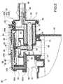
- FIG. 2shows a first embodiment of the IPMA 20 mounted on the charcoal canister 18 .
- the IPMA 20includes a housing 30 that can be mounted to the body of the charcoal anister 18 by a “bayonet” style attachment 32 .
- a seal 34is interposed between the charcoal canister 18 and the IPMA 20 .
- This attachment 32in combination with a snap finger 33 , allows the IPMA 20 to be readily serviced in the field.
- different styles of attachments between the IPMA 20 and the body 18can be substituted for the illustrated bayonet attachment 32 , e.g., a threaded attachment, an interlocking telescopic attachment, etc.
- the body 18 and the housing 30can be integrally formed from a common homogenous material, can be permanently bonded together (e.g., using an adhesive), or the body 18 and the housing 30 can be interconnected via an intermediate member such as a pipe or a flexible hose.
- the housing 30can be an assembly of a main housing piece 30 a and housing piece covers 30 b and 30 c . Although two housing piece covers 30 b , 30 c have been illustrated, it is desirable to minimize the number of housing pieces to reduce the number of potential leak points, i.e., between housing pieces, which must be sealed. Minimizing the number of housing piece covers depends largely on the fluid flow path configuration through the main housing piece 30 a and the manufacturing efficiency of incorporating the necessary components of the IPMA 20 via the ports of the flow path. Additional features of the housing 30 and the incorporation of components therein will be further described below.
- Signaling 22occurs when vacuum at the first predetermined pressure level is present in the charcoal canister 18 .
- a pressure operable device 36separates an interior chamber in the housing 30 .
- the pressure operable device 36which includes a diaphragm 38 that is operatively interconnected to a valve 40 , separates the interior chamber of the housing 30 into an upper portion 42 and a lower portion 44 .
- the upper portion 42is in fluid communication with the ambient atmospheric pressure through a first port 46 .
- the lower portion 44is in fluid communication with a second port 48 between housing 30 the charcoal canister 18 .
- the lower portion 44is also in fluid communicating with a separate portion 44 a via first and second signal passageways 50 , 52 .
- Orienting the opening of the first signal passageway 50 toward the charcoal canister 18yields unexpected advantages in providing fluid communication between the portions 44 , 44 a .
- Sealing between the housing pieces 30 a , 30 b for the second signal passageway 52can be provided by a protrusion 38 a of the diaphragm 38 that is penetrated by the second signal passageway 52 .
- a branch 52 aprovides fluid communication, over the seal bead of the diaphragm 38 , with the separate portion 44 a .
- a rubber plug 50 ais installed after the housing portion 30 a is molded. The force created as a result of vacuum in the separate portion 44 a causes the diaphragm 38 to be displaced toward the housing part 30 b .
- a resilient element 54e.g., a leaf spring.
- the bias of the resilient element 54can be adjusted by a calibrating screw 56 such that a desired level of vacuum, e.g., one inch of water, will depress a switch 58 that can be mounted on a printed circuit board 60 .
- the printed circuit boardis electrically connected via an intermediate lead frame 62 to an outlet terminal 64 supported by the housing part 30 c .
- An O-ring 66seals the housing part 30 c with respect to the housing part 30 a .
- vacuumis released, i.e., the pressure in the portions 44 , 44 a rises, the resilient element 54 pushes the diaphragm 38 away from the switch 58 , whereby the switch 58 resets.
- Pressure relieving 24occurs as vacuum in the portions 44 , 44 a increases, i.e., the pressure decreases below the calibration level for actuating the switch 58 .
- Vacuum in the charcoal canister 18 and the lower portion 44will continually act on the valve 40 inasmuch as the upper portion 42 is always at or near the ambient atmospheric pressure A.
- this vacuumwill overcome the opposing force of a second resilient element 68 and displace the valve 40 away from a lip seal 70 .
- This displacementwill open the valve 40 from its closed configuration, thus allowing ambient air to be drawn through the upper portion 42 into the lower the portion 44 . That is to say, in an open configuration of the valve 40 , the first and second ports 46 , 48 are in fluid communication. In this way, vacuum in the fuel system 10 can be regulated.
- Controllably connecting 28 to similarly displace the valve 40 from its closed configuration to its open configurationcan be provided by a solenoid 72 .
- the second resilient element 68displaces the valve 40 to its closed configuration.
- a ferrous armature 74which can be fixed to the valve 40 , can have a tapered tip that creates higher flux densities and therefore higher pull-in forces.
- a coil 76surrounds a solid ferrous core 78 that is isolated from the charcoal canister 18 by an O-ring 80 .
- the flux pathis completed by a ferrous strap 82 that serves to focus the flux back towards the armature 74 . When the coil 76 is energized, the resultant flux pulls the valve 40 toward the core 78 .
- the armature 74can be prevented from touching the core 78 by a tube 84 that sits inside the second resilient element 68 , thereby preventing magnetic lock-up. Since very little electrical power is required for the solenoid 72 to maintain the valve 40 in its open configuration, the power can be reduced to as little as 10% of the original power by pulse-width modulation. When electrical power is removed from the coil 76 , the second resilient element 68 pushes the armature 74 and the valve 40 to the normally closed configuration of the valve 40 .
- Relieving pressure 26is provided when there is a positive pressure in the lower portion 44 , e.g., when the tank 12 is being refueled.
- the valve 40is displaced to its open configuration to provide a very low restriction path for escaping air from the tank 12 .
- the first and second signal passageways 50 , 52communicate this positive pressure to the separate portion 44 a .
- this positive pressuredisplaces the diaphragm 38 downward toward the valve 40 .
- a diaphragm pin 39transfers the displacement of the diaphragm 38 to the valve 40 , thereby displacing the valve 40 to its open configuration with respect to the lip seal 70 .
- pressure in the charcoal canister 18 due to refuelingis allowed to escape through the lower portion 44 , past the lip seal 70 , through the upper portion 42 , and through the second port 46 .
- Relieving pressure 26is also useful for regulating the pressure in fuel tank 12 during any situation in which the engine is turned off. By limiting the amount of positive pressure in the fuel tank 12 , the cool-down vacuum effect will take place sooner.
- FIG. 3shows a second embodiment of the present invention that is substantially similar to the first embodiment shown in FIG. 2, except that the first and second signal passageways 50 , 52 have been eliminated, and the intermediate lead frame 62 penetrates a protrusion 38 b of the diaphragm 38 , similar to the penetration of protrusion 38 a by the second signal passageway 52 , as shown in FIG. 2 .
- the signal from the lower portion 44is communicated to the separate portion 44 a via a path that extends through spaces between the solenoid 72 and the housing 30 , through spaces between the intermediate lead frame 62 and the housing 30 , and through the penetration in the protrusion 38 b.
- the present inventionhas many advantages, including:
- vacuum reliefprovides fail-safe operation of the purge flow system in the event that the solenoid fails with the valve in a closed configuration.
- integrally packaging the sensor/switch, the valve, and the solenoid in a single unitreduces the number of electrical connectors and improves system integrity since there are fewer leak points, i.e., possible openings in the system.
Landscapes
- Engineering & Computer Science (AREA)
- Chemical & Material Sciences (AREA)
- Combustion & Propulsion (AREA)
- Mechanical Engineering (AREA)
- General Engineering & Computer Science (AREA)
- Supplying Secondary Fuel Or The Like To Fuel, Air Or Fuel-Air Mixtures (AREA)
Abstract
Description
This application claims the benefit of the earlier filing date of U.S. Provisional Application Ser. No. 60/166,404, filed Nov. 19, 1999, which is incorporated by reference herein in its entirety.
The present invention relates to an integrated pressure management system that manages pressure and detects leaks in a fuel system. The present invention also relates to an integrated pressure management system that performs a leak diagnostic for the headspace in a fuel tank, a canister that collects volatile fuel vapors from the headspace, a purge valve, and all associated hoses.
In a conventional pressure management system for a vehicle, fuel vapor that escapes from a fuel tank is stored in a canister. If there is a leak in the fuel tank, canister or any other component of the vapor handling system, some fuel vapor could exit through the leak to escape into the atmosphere instead of being stored in the canister. Thus, it is desirable to detect leaks.
In such conventional pressure management systems, excess fuel vapor accumulates immediately after engine shutdown, thereby creating a positive pressure in the fuel vapor management system. Thus, it is desirable to vent, or “blow-off,” through the canister, this excess fuel vapor and to facilitate vacuum generation in the fuel vapor management system. Similarly, it is desirable to relieve positive pressure during tank refueling by allowing air to exit the tank at high flow rates. This is commonly referred to as onboard refueling vapor recovery (ORVR).
According to the present invention, a sensor or switch signals that a predetermined pressure exists. In particular, the sensor/switch signals that a predetermined vacuum exists. As it is used herein, “pressure” is measured relative to the ambient atmospheric pressure. Thus, positive pressure refers to pressure greater than the ambient atmospheric pressure and negative pressure, or “vacuum,” refers to pressure less than the ambient atmospheric pressure.
The present invention is achieved by providing an integrated pressure management apparatus. The apparatus comprises a housing defining an interior chamber, the housing including first and second ports communicating with the interior chamber; a pressure operable device separating the chamber into a first portion and a second portion, the first portion communicating with the first port, the second portion communicating with the second port, the pressure operable device permitting fluid communication between the first and second ports in a first configuration and preventing fluid communication between the first and second ports in a second configuration; a signal chamber in fluid communication with the first portion of the interior chamber, the pressure operable device further separating the signal chamber from the second portion of the interior chamber; and a passageway through the housing, the passageway providing the fluid communication between the first portion of the interior chamber and the signal chamber.
The accompanying drawings, which are incorporated herein and constitute part of this specification, illustrate the present invention, and, together with the general description given above and the detailed description given below, serve to explain features of the invention. Like reference numerals are used to identify similar features.
FIG. 1 is a schematic illustration showing the operation of an apparatus according to the present invention.
FIG. 2 is a cross-sectional view of a first embodiment of the apparatus according to the present invention
FIG. 3 is a cross-sectional view of a second embodiment of the apparatus according to the present invention.
Referring to FIG. 1, afuel system 10, e.g., for an engine (not shown), includes afuel tank 12, avacuum source 14 such as an intake manifold of the engine, apurge valve 16, acharcoal canister 18, and an integrated pressure management system (IPMA)20.
The IPMA20 performs a plurality of functions including signaling22 that a first predetermined pressure (vacuum) level exists, relievingpressure 24 at a value below the first predetermined pressure level, relievingpressure 26 above a second pressure level, and controllably connecting28 thecharcoal canister 18 to the ambient atmospheric pressure A.
In the course of cooling that is experienced by thefuel system 10, e.g., after the engine is turned off, a vacuum is created in thetank 12 andcharcoal canister 18. The existence of a vacuum at the first predetermined pressure level indicates that the integrity of thefuel system 10 is satisfactory. Thus,signaling 22 is used for indicating the integrity of thefuel system 10, i.e., that there are no leaks. Subsequently relievingpressure 24 at a pressure level below the first predetermined pressure level protects the integrity of thefuel tank 12, i.e., prevents it from collapsing due to vacuum in thefuel system 10. Relievingpressure 24 also prevents “dirty” air from being drawn into thetank 12.
Immediately after the engine is turned off, relievingpressure 26 allows excess pressure due to fuel vaporization to blow off, thereby facilitating the desired vacuum generation that occurs during cooling. During blow off, air within thefuel system 10 is released while fuel molecules are retained. Similarly, in the course of refueling thefuel tank 12, relievingpressure 26 allows air to exit thefuel tank 12 at high flow.
While the engine is turned on, controllably connecting28 thecanister 18 to the ambient air A allows confirmation of the purge flow and allows confirmation of the signaling22 performance. While the engine is turned off, controllably connecting28 allows a computer for the engine to monitor the vacuum generated during cooling.
FIG. 2, shows a first embodiment of the IPMA20 mounted on thecharcoal canister 18. The IPMA20 includes ahousing 30 that can be mounted to the body of thecharcoal anister 18 by a “bayonet”style attachment 32. Aseal 34 is interposed between thecharcoal canister 18 and the IPMA20. Thisattachment 32, in combination with asnap finger 33, allows the IPMA20 to be readily serviced in the field. Of course, different styles of attachments between the IPMA20 and thebody 18 can be substituted for the illustratedbayonet attachment 32, e.g., a threaded attachment, an interlocking telescopic attachment, etc. Alternatively, thebody 18 and thehousing 30 can be integrally formed from a common homogenous material, can be permanently bonded together (e.g., using an adhesive), or thebody 18 and thehousing 30 can be interconnected via an intermediate member such as a pipe or a flexible hose.
Thehousing 30 can be an assembly of amain housing piece 30aand housing piece covers30band30c. Although two housing piece covers30b,30chave been illustrated, it is desirable to minimize the number of housing pieces to reduce the number of potential leak points, i.e., between housing pieces, which must be sealed. Minimizing the number of housing piece covers depends largely on the fluid flow path configuration through themain housing piece 30aand the manufacturing efficiency of incorporating the necessary components of the IPMA20 via the ports of the flow path. Additional features of thehousing 30 and the incorporation of components therein will be further described below.
Pressure relieving24 occurs as vacuum in theportions switch 58. Vacuum in thecharcoal canister 18 and thelower portion 44 will continually act on thevalve 40 inasmuch as theupper portion 42 is always at or near the ambient atmospheric pressure A. At some value of vacuum below the first predetermined level, e.g., six inches of water, this vacuum will overcome the opposing force of a secondresilient element 68 and displace thevalve 40 away from alip seal 70. This displacement will open thevalve 40 from its closed configuration, thus allowing ambient air to be drawn through theupper portion 42 into the lower theportion 44. That is to say, in an open configuration of thevalve 40, the first andsecond ports fuel system 10 can be regulated.
Controllably connecting28 to similarly displace thevalve 40 from its closed configuration to its open configuration can be provided by asolenoid 72. At rest, the secondresilient element 68 displaces thevalve 40 to its closed configuration. Aferrous armature 74, which can be fixed to thevalve 40, can have a tapered tip that creates higher flux densities and therefore higher pull-in forces. Acoil 76 surrounds a solidferrous core 78 that is isolated from thecharcoal canister 18 by an O-ring 80. The flux path is completed by aferrous strap 82 that serves to focus the flux back towards thearmature 74. When thecoil 76 is energized, the resultant flux pulls thevalve 40 toward thecore 78. Thearmature 74 can be prevented from touching thecore 78 by atube 84 that sits inside the secondresilient element 68, thereby preventing magnetic lock-up. Since very little electrical power is required for thesolenoid 72 to maintain thevalve 40 in its open configuration, the power can be reduced to as little as 10% of the original power by pulse-width modulation. When electrical power is removed from thecoil 76, the secondresilient element 68 pushes thearmature 74 and thevalve 40 to the normally closed configuration of thevalve 40.
Relievingpressure 26 is provided when there is a positive pressure in thelower portion 44, e.g., when thetank 12 is being refueled. Specifically, thevalve 40 is displaced to its open configuration to provide a very low restriction path for escaping air from thetank 12. When thecharcoal canister 18, and hence thelower portions 44, experience positive pressure above ambient atmospheric pressure, the first andsecond signal passageways separate portion 44a. In turn, this positive pressure displaces thediaphragm 38 downward toward thevalve 40. Adiaphragm pin 39 transfers the displacement of thediaphragm 38 to thevalve 40, thereby displacing thevalve 40 to its open configuration with respect to thelip seal 70. Thus, pressure in thecharcoal canister 18 due to refueling is allowed to escape through thelower portion 44, past thelip seal 70, through theupper portion 42, and through thesecond port 46.
Relievingpressure 26 is also useful for regulating the pressure infuel tank 12 during any situation in which the engine is turned off. By limiting the amount of positive pressure in thefuel tank 12, the cool-down vacuum effect will take place sooner.
FIG. 3 shows a second embodiment of the present invention that is substantially similar to the first embodiment shown in FIG. 2, except that the first andsecond signal passageways intermediate lead frame 62 penetrates aprotrusion 38bof thediaphragm 38, similar to the penetration ofprotrusion 38aby thesecond signal passageway 52, as shown in FIG.2. The signal from thelower portion 44 is communicated to theseparate portion 44avia a path that extends through spaces between thesolenoid 72 and thehousing 30, through spaces between theintermediate lead frame 62 and thehousing 30, and through the penetration in theprotrusion 38b.
The present invention has many advantages, including:
providing relief for positive pressure above a first predetermined pressure value, and providing relief for vacuum below a second predetermined pressure value.
vacuum monitoring with the present invention in its open configuration during natural cooling, e.g., after the engine is turned off, provides a leak detection diagnostic.
driving the present invention into its open configuration while the engine is on confirms purge flow and switch/sensor function.
vacuum relief provides fail-safe operation of the purge flow system in the event that the solenoid fails with the valve in a closed configuration.
integrally packaging the sensor/switch, the valve, and the solenoid in a single unit reduces the number of electrical connectors and improves system integrity since there are fewer leak points, i.e., possible openings in the system.
While the invention has been disclosed with reference to certain preferred embodiments, numerous modifications, alterations, and changes to the described embodiments are possible without departing from the sphere and scope of the invention, as defined in the appended claims and their equivalents thereof. Accordingly, it is intended that the invention not be limited to the described embodiments, but that it have the full scope defined by the language of the following claims.
Claims (8)
1. An integrated pressure management apparatus comprising:
a housing defining an interior chamber, the housing including first and second ports communicating with the interior chamber;
a pressure operable device separating the chamber into a first portion and a second portion, the first portion communicating with the first port, the second portion communicating with the second port, the pressure operable device permitting fluid communication between the first and second ports in a first configuration and preventing fluid communication between the first and second ports in a second configuration;
a signal chamber in fluid communication with the first portion of the interior chamber, the pressure operable device further separating the signal chamber from the second portion of the interior chamber;
a solenoid displacing the pressure operable device from the first configuration to the second configuration; and
a passageway through the housing, the passageway providing the fluid communication between the first portion of the interior chamber and the signal chamber, the passageway being defined at least in part by a void between the housing and the solenoid.
2. The integrated pressure management apparatus according toclaim 1 , wherein the passageway includes an opening generally confronting the first port.
3. The integrated pressure management apparatus according toclaim 1 , wherein the pressure operable device includes a diaphragm separating the signal chamber and the second portion of the interior chamber.
4. The integrated pressure management apparatus according toclaim 3 , wherein the diaphragm includes a protrusion, and the passageway penetrates the protrusion.
5. The integrated pressure management apparatus according toclaim 1 , wherein the housing is an assembly of a minimum number of components with seals therebetween such that a number of possible leak points with respect to the interior chamber is minimized.
6. The integrated pressure management apparatus according toclaim 1 , further comprising:
a switch signaling displacement of the pressure operable device in response to negative pressure at a first pressure level in the first portion of the interior chamber.
7. The integrated pressure management apparatus according toclaim 1 , wherein the switch is disposed within the housing.
8. The integrated pressure management apparatus according toclaim 7 , wherein the switch is generally enclosed by the signal chamber.
Priority Applications (2)
| Application Number | Priority Date | Filing Date | Title |
|---|---|---|---|
| US09/566,138US6470861B1 (en) | 1999-11-19 | 2000-05-05 | Fluid flow through an integrated pressure management apparatus |
| US10/281,262US6840232B2 (en) | 1999-11-19 | 2002-10-28 | Fluid flow through an integrated pressure management apparatus |
Applications Claiming Priority (2)
| Application Number | Priority Date | Filing Date | Title |
|---|---|---|---|
| US16640499P | 1999-11-19 | 1999-11-19 | |
| US09/566,138US6470861B1 (en) | 1999-11-19 | 2000-05-05 | Fluid flow through an integrated pressure management apparatus |
Related Child Applications (1)
| Application Number | Title | Priority Date | Filing Date |
|---|---|---|---|
| US10/281,262ContinuationUS6840232B2 (en) | 1999-11-19 | 2002-10-28 | Fluid flow through an integrated pressure management apparatus |
Publications (1)
| Publication Number | Publication Date |
|---|---|
| US6470861B1true US6470861B1 (en) | 2002-10-29 |
Family
ID=26862238
Family Applications (2)
| Application Number | Title | Priority Date | Filing Date |
|---|---|---|---|
| US09/566,138Expired - Fee RelatedUS6470861B1 (en) | 1999-11-19 | 2000-05-05 | Fluid flow through an integrated pressure management apparatus |
| US10/281,262Expired - Fee RelatedUS6840232B2 (en) | 1999-11-19 | 2002-10-28 | Fluid flow through an integrated pressure management apparatus |
Family Applications After (1)
| Application Number | Title | Priority Date | Filing Date |
|---|---|---|---|
| US10/281,262Expired - Fee RelatedUS6840232B2 (en) | 1999-11-19 | 2002-10-28 | Fluid flow through an integrated pressure management apparatus |
Country Status (1)
| Country | Link |
|---|---|
| US (2) | US6470861B1 (en) |
Cited By (9)
| Publication number | Priority date | Publication date | Assignee | Title |
|---|---|---|---|---|
| US20040226544A1 (en)* | 2003-03-07 | 2004-11-18 | Vdo Automotive Corporation | Electrical connections for an integrated pressure management apparatus |
| US20040237630A1 (en)* | 1997-10-02 | 2004-12-02 | Siemens Canada Limited | Temperature correction method and subsystem for automotive evaporative leak detection systems |
| US6840232B2 (en)* | 1999-11-19 | 2005-01-11 | Siemens Vdo Automotive Inc. | Fluid flow through an integrated pressure management apparatus |
| WO2014011161A1 (en)* | 2012-07-11 | 2014-01-16 | Continental Automotive Systems, Inc. | Articulating poppet to seal a natural vacuum leak detection device |
| US9206772B2 (en) | 2011-07-11 | 2015-12-08 | Continental Automotive Systems, Inc. | Articulating poppet to seal a natural vacuum leak detection device |
| US20180356271A1 (en)* | 2016-02-17 | 2018-12-13 | HELLA GmbH & Co. KGaA | Method and apparatus for detecting the liquid level in a liquid reservoir |
| US12158124B2 (en) | 2021-07-09 | 2024-12-03 | Stant Usa Corp. | Carbon canister with integrated fuel tank isolation valve |
| US12194836B2 (en) | 2021-10-18 | 2025-01-14 | Stant Usa Corp. | Carbon canister with direct connect fuel tank isolation valve |
| US12280656B2 (en) | 2021-10-18 | 2025-04-22 | Stant Usa Corp. | Carbon canister with direct connect fuel tank isolation valve |
Families Citing this family (1)
| Publication number | Priority date | Publication date | Assignee | Title |
|---|---|---|---|---|
| US7856965B2 (en)* | 2007-11-27 | 2010-12-28 | Continental Automotive Canada | Natural vacuum leak detection device using diaphragm-seal mechanism |
Citations (91)
| Publication number | Priority date | Publication date | Assignee | Title |
|---|---|---|---|---|
| US3110502A (en) | 1957-11-29 | 1963-11-12 | Surelock Mfg Co Inc | Packing for hydraulic power units |
| US3190322A (en) | 1962-10-03 | 1965-06-22 | J C Carter Company | Aircraft under-wing fueling nozzle and valve and sealing means therefor |
| US3413840A (en) | 1966-04-19 | 1968-12-03 | Mcmullen John J | Leak detection system |
| US3516279A (en) | 1967-02-23 | 1970-06-23 | Alphamatic Corp | Method for adjusting a pressure operated switch utilizing the nonlinear properties of a biasing means |
| US3586016A (en) | 1970-01-22 | 1971-06-22 | Ford Motor Co | Fuel tank liquid vapor separator system having attitude sensing means |
| US3640501A (en) | 1969-10-02 | 1972-02-08 | George W Walton | Valve seal ring including metal retainer rings |
| US3720090A (en) | 1968-12-30 | 1973-03-13 | Texas Instruments Inc | Switch with improved means and method for calibration |
| US3754568A (en)* | 1971-10-14 | 1973-08-28 | Nupro Co | Check valve |
| US3802267A (en) | 1973-02-05 | 1974-04-09 | Universal Lancaster Corp | Gas meter diaphragm |
| US3841344A (en) | 1973-06-06 | 1974-10-15 | Airco Inc | Gas mixing systems |
| US3861646A (en) | 1972-10-27 | 1975-01-21 | Dresser Ind | Dual sealing element valve for oil well pumps |
| US3927553A (en) | 1973-10-18 | 1975-12-23 | Lanier Frantz | Testing fitting for pressure-responsive devices |
| US4009985A (en) | 1975-08-08 | 1977-03-01 | Hirt Combustion Engineers | Method and apparatus for abatement of gasoline vapor emissions |
| US4136854A (en) | 1975-07-01 | 1979-01-30 | Vat Aktiengesellschaft Fur Vakuum-Apparate-Technik | All-metal lift valve for high-vacuum applications |
| US4164168A (en) | 1976-04-13 | 1979-08-14 | Tokico Ltd. | Vacuum booster device |
| US4166485A (en) | 1973-04-16 | 1979-09-04 | Wokas Albert L | Gasoline vapor emission control |
| US4215846A (en) | 1977-04-01 | 1980-08-05 | Honeywell Inc. | Multiportion unitary valve seat and valve incorporating it |
| US4240467A (en) | 1979-01-15 | 1980-12-23 | Blatt L Douglas | Valve assembly |
| US4244554A (en)* | 1979-04-02 | 1981-01-13 | Automatic Switch Company | Springless diaphragm valve |
| US4354383A (en) | 1979-09-20 | 1982-10-19 | Bosch & Pierburg System Ohg | Method of and device for measuring the amount of liquid fuel in a tank |
| US4368366A (en) | 1980-01-23 | 1983-01-11 | Aisin Seiki Kabushiki Kaisha | Pneumatically operated device with valve and switch mechanisms |
| US4474208A (en) | 1983-04-13 | 1984-10-02 | Baird Manufacturing Company | Safety valve |
| US4494571A (en) | 1982-11-08 | 1985-01-22 | Wabco Fahrzeugbremsen Gmbh | Electropneumatic door control valve |
| US4518329A (en) | 1984-03-30 | 1985-05-21 | Weaver Joe T | Wear resistant pump valve |
| US4561297A (en) | 1983-11-03 | 1985-12-31 | V L Churchill Limited | Hand-held diesel engine injection tester |
| US4616114A (en) | 1984-11-19 | 1986-10-07 | Texas Instruments Incorporated | Pressure responsive switch having little or no differential between actuation release pressure levels |
| US4717117A (en) | 1986-12-08 | 1988-01-05 | Bendix Electronics Limited | Vacuum valve using improved diaphragm |
| US4766557A (en) | 1986-06-20 | 1988-08-23 | Westinghouse Electric Corp. | Apparatus for monitoring hydrogen gas leakage into the stator coil water cooling system of a hydrogen cooled electric generator |
| US4766927A (en) | 1987-01-29 | 1988-08-30 | Scott & Fetzer Company | Abrasive fluid control valve with plastic seat |
| US4852054A (en) | 1986-11-20 | 1989-07-25 | Nde Technology, Inc. | Volumetric leak detection system for underground storage tanks and the like |
| US4901559A (en) | 1986-07-18 | 1990-02-20 | Werner Grabner | Method and arrangement for measuring the vapor pressure of liquids |
| US4905505A (en) | 1989-03-03 | 1990-03-06 | Atlantic Richfield Company | Method and system for determining vapor pressure of liquid compositions |
| US4925157A (en)* | 1989-05-26 | 1990-05-15 | Leonard Troy | Solenoid-operated control apparatus |
| US5036823A (en) | 1990-08-17 | 1991-08-06 | General Motors Corporation | Combination overfill and tilt shutoff valve system for vehicle fuel tank |
| US5069188A (en) | 1991-02-15 | 1991-12-03 | Siemens Automotive Limited | Regulated canister purge solenoid valve having improved purging at engine idle |
| US5090234A (en) | 1990-08-30 | 1992-02-25 | Vista Research, Inc. | Positive displacement pump apparatus and methods for detection of leaks in pressurized pipeline systems |
| US5096029A (en) | 1988-07-23 | 1992-03-17 | Suspa Compart Ag | Longitudinally controllable adjustment device |
| US5101710A (en) | 1990-05-14 | 1992-04-07 | Bebco Industries, Inc. | Control apparatus or system for purged and pressurized enclosures for electrical equipment |
| US5116257A (en)* | 1991-01-08 | 1992-05-26 | Stant Inc. | Tank venting control assembly |
| US5193512A (en)* | 1990-02-08 | 1993-03-16 | Robert Bosch Gmbh | Tank-venting system for a motor vehicle and method for checking the operability thereof |
| US5209210A (en)* | 1990-08-10 | 1993-05-11 | Aisan Kogyo Kabushiki Kaisha | Evaporative emission control system |
| US5211151A (en)* | 1991-02-27 | 1993-05-18 | Honda Giken Kogyo Kabushiki Kaisha (Honda Motor Co., Ltd.) | Apparatus for restricting discharge of evaporated fuel gas |
| US5253629A (en)* | 1992-02-03 | 1993-10-19 | General Motors Corporation | Flow sensor for evaporative control system |
| US5259424A (en) | 1991-06-27 | 1993-11-09 | Dvco, Inc. | Method and apparatus for dispensing natural gas |
| US5263462A (en) | 1992-10-29 | 1993-11-23 | General Motors Corporation | System and method for detecting leaks in a vapor handling system |
| US5273071A (en) | 1992-03-05 | 1993-12-28 | Dover Corporation | Dry disconnect couplings |
| US5317909A (en)* | 1991-04-02 | 1994-06-07 | Nippondenso Co., Ltd. | Abnormality detecting apparatus for use in fuel transpiration prevention systems |
| US5327934A (en) | 1993-06-07 | 1994-07-12 | Ford Motor Copany | Automotive fuel tank pressure control valve |
| US5337262A (en) | 1991-12-03 | 1994-08-09 | Hr Textron Inc. | Apparatus for and method of testing hydraulic/pneumatic apparatus using computer controlled test equipment |
| US5372032A (en) | 1993-04-23 | 1994-12-13 | Filippi; Ernest A. | Pressurized piping line leak detector |
| US5388613A (en) | 1993-01-13 | 1995-02-14 | Dragerwerk Ag | Valve with pressure compensation |
| US5390643A (en) | 1993-01-13 | 1995-02-21 | Fuji Jukogyo Kabushiki Kaisha | Pressure control apparatus for fuel tank |
| US5390645A (en) | 1994-03-04 | 1995-02-21 | Siemens Electric Limited | Fuel vapor leak detection system |
| US5415033A (en) | 1990-08-30 | 1995-05-16 | Vista Research, Inc. | Simplified apparatus for detection of leaks in pressurized pipelines |
| US5429097A (en)* | 1992-12-08 | 1995-07-04 | Firma Carl Freudenberg | Device for feeding vapors of a fuel tank into an internal combustion engine |
| US5437257A (en)* | 1994-02-28 | 1995-08-01 | General Motors Corporation | Evaporative emission control system with vent valve |
| US5474050A (en) | 1995-01-13 | 1995-12-12 | Siemens Electric Limited | Leak detection pump with integral vent seal |
| EP0688691A1 (en) | 1994-06-16 | 1995-12-27 | Robert Bosch Gmbh | Pump device for a tank system of internal combustion engines |
| US5507176A (en) | 1994-03-28 | 1996-04-16 | K-Line Industries, Inc. | Evaporative emissions test apparatus and method |
| US5524662A (en) | 1990-01-25 | 1996-06-11 | G.T. Products, Inc. | Fuel tank vent system and diaphragm valve for such system |
| US5564306A (en) | 1994-05-25 | 1996-10-15 | Marcum Fuel Systems, Inc. | Density compensated gas flow meter |
| US5579742A (en) | 1994-12-28 | 1996-12-03 | Honda Giken Kogyo Kabushiki Kaisha | Evaporative emission control system for internal combustion engines |
| US5584271A (en) | 1995-11-14 | 1996-12-17 | Freudenberg-Nok General Partnership | Valve stem seal |
| US5603349A (en) | 1992-01-17 | 1997-02-18 | Stant Manufacturing Inc. | Tank venting system |
| US5614665A (en) | 1995-08-16 | 1997-03-25 | Ford Motor Company | Method and system for monitoring an evaporative purge system |
| US5635630A (en) | 1992-12-23 | 1997-06-03 | Chrysler Corporation | Leak detection assembly |
| US5644072A (en) | 1994-03-28 | 1997-07-01 | K-Line Industries, Inc. | Evaporative emissions test apparatus and method |
| US5671718A (en) | 1995-10-23 | 1997-09-30 | Ford Global Technologies, Inc. | Method and system for controlling a flow of vapor in an evaporative system |
| US5681151A (en) | 1996-03-18 | 1997-10-28 | Devilbiss Air Power Company | Motor driven air compressor having a combined vent valve and check valve assembly |
| US5687633A (en) | 1996-07-09 | 1997-11-18 | Westinghouse Air Brake Company | Insert type member for use in a flexible type pump diaphragm |
| US5743169A (en) | 1995-01-06 | 1998-04-28 | Yamada T.S. Co., Ltd. | Diaphragm assembly and method of manufacturing same |
| US5803056A (en)* | 1997-02-12 | 1998-09-08 | Siemens Electric Limited | Canister vent valve having electric pressure sensor and valve actuator |
| US5826566A (en) | 1996-07-26 | 1998-10-27 | Honda Giken Kogyo Kabushiki Kaisha | Evaporative fuel-processing system for internal combustion engines |
| US5863025A (en)* | 1995-03-27 | 1999-01-26 | Kyosan Denki Co., Ltd. | Evaporator control valve provided with a solenoid for use in diagnosing trouble |
| US5878729A (en)* | 1998-05-06 | 1999-03-09 | General Motors Corporation | Air control valve assembly for fuel evaporative emission storage canister |
| US5884609A (en) | 1994-05-09 | 1999-03-23 | Nissan Motor Co., Ltd. | Air/fuel ratio control apparatus |
| US5893389A (en) | 1997-08-08 | 1999-04-13 | Fmc Corporation | Metal seals for check valves |
| US5894784A (en) | 1998-08-10 | 1999-04-20 | Ingersoll-Rand Company | Backup washers for diaphragms and diaphragm pump incorporating same |
| US5911209A (en) | 1996-11-05 | 1999-06-15 | Nissan Motor Co., Ltd. | Fuel vapor processor diagnostic device |
| WO1999050551A1 (en) | 1998-03-27 | 1999-10-07 | Siemens Canada Limited | Automotive evaporative leak detection system |
| US5979869A (en) | 1997-02-18 | 1999-11-09 | Press Controls Ag Rumland | Valve |
| US6003499A (en) | 1998-01-07 | 1999-12-21 | Stant Manufacturing Inc. | Tank vent control apparatus |
| US6053151A (en)* | 1997-09-08 | 2000-04-25 | Siemens Canada Limited | Automotive evaporative emission leak detection system and module |
| US6073487A (en) | 1998-08-10 | 2000-06-13 | Chrysler Corporation | Evaporative system leak detection for an evaporative emission control system |
| US6089081A (en) | 1998-01-27 | 2000-07-18 | Siemens Canada Limited | Automotive evaporative leak detection system and method |
| US6142062A (en) | 1999-01-13 | 2000-11-07 | Westinghouse Air Brake Company | Diaphragm with modified insert |
| US6145430A (en) | 1998-06-30 | 2000-11-14 | Ingersoll-Rand Company | Selectively bonded pump diaphragm |
| US6168168B1 (en) | 1998-09-10 | 2001-01-02 | Albert W. Brown | Fuel nozzle |
| US6202688B1 (en) | 1996-04-30 | 2001-03-20 | Gfi Control Systems Inc. | Instant-on vented tank valve with manual override and method of operation thereof |
| US6203022B1 (en) | 1996-04-17 | 2001-03-20 | Lucas Industries Public Limited | Annular sealing element |
| US6328021B1 (en) | 1999-11-19 | 2001-12-11 | Siemens Canada Limited | Diaphragm for an integrated pressure management apparatus |
Family Cites Families (13)
| Publication number | Priority date | Publication date | Assignee | Title |
|---|---|---|---|---|
| DE3519292A1 (en) | 1985-05-30 | 1986-12-04 | Robert Bosch Gmbh, 7000 Stuttgart | DISPENSING SYSTEM FOR INITIATING VAPORIZED FUEL INTO AN INTERNAL COMBUSTION ENGINE |
| CA2043204A1 (en) | 1990-06-20 | 1991-12-21 | Tibor Baron | Proportional solenoid valve controlled evaporative emissions purge system |
| DE9013153U1 (en) | 1990-09-15 | 1990-12-20 | Pierburg AG, 41460 Neuss | Flow or pressure switch for a fluid line |
| FR2671597B1 (en) | 1991-01-16 | 1993-07-09 | Eaton Sa Monaco | SOLENOID VALVE WITH VARIABLE PASSAGE SECTION. |
| US5191870A (en) | 1991-03-28 | 1993-03-09 | Siemens Automotive Limited | Diagnostic system for canister purge system |
| US6474313B1 (en)* | 1999-11-19 | 2002-11-05 | Siemens Canada Limited | Connection between an integrated pressure management apparatus and a vapor collection canister |
| US6460566B1 (en) | 1999-11-19 | 2002-10-08 | Siemens Canada Limited | Integrated pressure management system for a fuel system |
| US6450153B1 (en)* | 1999-11-19 | 2002-09-17 | Siemens Canada Limited | Integrated pressure management apparatus providing an on-board diagnostic |
| US6470908B1 (en)* | 1999-11-19 | 2002-10-29 | Siemens Canada Limited | Pressure operable device for an integrated pressure management apparatus |
| US6470861B1 (en)* | 1999-11-19 | 2002-10-29 | Siemens Canada Limited | Fluid flow through an integrated pressure management apparatus |
| US6453942B1 (en)* | 1999-11-19 | 2002-09-24 | Siemens Canada Limited | Housing for integrated pressure management apparatus |
| US6478045B1 (en)* | 1999-11-19 | 2002-11-12 | Siemens Canada Limited | Solenoid for an integrated pressure management apparatus |
| US6474314B1 (en)* | 1999-11-19 | 2002-11-05 | Siemens Canada Limited | Fuel system with intergrated pressure management |
- 2000
- 2000-05-05USUS09/566,138patent/US6470861B1/ennot_activeExpired - Fee Related
- 2002
- 2002-10-28USUS10/281,262patent/US6840232B2/ennot_activeExpired - Fee Related
Patent Citations (92)
| Publication number | Priority date | Publication date | Assignee | Title |
|---|---|---|---|---|
| US3110502A (en) | 1957-11-29 | 1963-11-12 | Surelock Mfg Co Inc | Packing for hydraulic power units |
| US3190322A (en) | 1962-10-03 | 1965-06-22 | J C Carter Company | Aircraft under-wing fueling nozzle and valve and sealing means therefor |
| US3413840A (en) | 1966-04-19 | 1968-12-03 | Mcmullen John J | Leak detection system |
| US3516279A (en) | 1967-02-23 | 1970-06-23 | Alphamatic Corp | Method for adjusting a pressure operated switch utilizing the nonlinear properties of a biasing means |
| US3720090A (en) | 1968-12-30 | 1973-03-13 | Texas Instruments Inc | Switch with improved means and method for calibration |
| US3640501A (en) | 1969-10-02 | 1972-02-08 | George W Walton | Valve seal ring including metal retainer rings |
| US3586016A (en) | 1970-01-22 | 1971-06-22 | Ford Motor Co | Fuel tank liquid vapor separator system having attitude sensing means |
| US3754568A (en)* | 1971-10-14 | 1973-08-28 | Nupro Co | Check valve |
| US3861646A (en) | 1972-10-27 | 1975-01-21 | Dresser Ind | Dual sealing element valve for oil well pumps |
| US3802267A (en) | 1973-02-05 | 1974-04-09 | Universal Lancaster Corp | Gas meter diaphragm |
| US4166485A (en) | 1973-04-16 | 1979-09-04 | Wokas Albert L | Gasoline vapor emission control |
| US3841344A (en) | 1973-06-06 | 1974-10-15 | Airco Inc | Gas mixing systems |
| US3927553A (en) | 1973-10-18 | 1975-12-23 | Lanier Frantz | Testing fitting for pressure-responsive devices |
| US4136854A (en) | 1975-07-01 | 1979-01-30 | Vat Aktiengesellschaft Fur Vakuum-Apparate-Technik | All-metal lift valve for high-vacuum applications |
| US4009985A (en) | 1975-08-08 | 1977-03-01 | Hirt Combustion Engineers | Method and apparatus for abatement of gasoline vapor emissions |
| US4164168A (en) | 1976-04-13 | 1979-08-14 | Tokico Ltd. | Vacuum booster device |
| US4215846A (en) | 1977-04-01 | 1980-08-05 | Honeywell Inc. | Multiportion unitary valve seat and valve incorporating it |
| US4240467A (en) | 1979-01-15 | 1980-12-23 | Blatt L Douglas | Valve assembly |
| US4244554A (en)* | 1979-04-02 | 1981-01-13 | Automatic Switch Company | Springless diaphragm valve |
| US4354383A (en) | 1979-09-20 | 1982-10-19 | Bosch & Pierburg System Ohg | Method of and device for measuring the amount of liquid fuel in a tank |
| US4368366A (en) | 1980-01-23 | 1983-01-11 | Aisin Seiki Kabushiki Kaisha | Pneumatically operated device with valve and switch mechanisms |
| US4494571A (en) | 1982-11-08 | 1985-01-22 | Wabco Fahrzeugbremsen Gmbh | Electropneumatic door control valve |
| US4474208A (en) | 1983-04-13 | 1984-10-02 | Baird Manufacturing Company | Safety valve |
| US4561297A (en) | 1983-11-03 | 1985-12-31 | V L Churchill Limited | Hand-held diesel engine injection tester |
| US4518329A (en) | 1984-03-30 | 1985-05-21 | Weaver Joe T | Wear resistant pump valve |
| US4616114A (en) | 1984-11-19 | 1986-10-07 | Texas Instruments Incorporated | Pressure responsive switch having little or no differential between actuation release pressure levels |
| US4766557A (en) | 1986-06-20 | 1988-08-23 | Westinghouse Electric Corp. | Apparatus for monitoring hydrogen gas leakage into the stator coil water cooling system of a hydrogen cooled electric generator |
| US4901559A (en) | 1986-07-18 | 1990-02-20 | Werner Grabner | Method and arrangement for measuring the vapor pressure of liquids |
| US4852054A (en) | 1986-11-20 | 1989-07-25 | Nde Technology, Inc. | Volumetric leak detection system for underground storage tanks and the like |
| US4717117A (en) | 1986-12-08 | 1988-01-05 | Bendix Electronics Limited | Vacuum valve using improved diaphragm |
| US4766927A (en) | 1987-01-29 | 1988-08-30 | Scott & Fetzer Company | Abrasive fluid control valve with plastic seat |
| US5096029A (en) | 1988-07-23 | 1992-03-17 | Suspa Compart Ag | Longitudinally controllable adjustment device |
| US4905505A (en) | 1989-03-03 | 1990-03-06 | Atlantic Richfield Company | Method and system for determining vapor pressure of liquid compositions |
| US4925157A (en)* | 1989-05-26 | 1990-05-15 | Leonard Troy | Solenoid-operated control apparatus |
| US5524662A (en) | 1990-01-25 | 1996-06-11 | G.T. Products, Inc. | Fuel tank vent system and diaphragm valve for such system |
| US5193512A (en)* | 1990-02-08 | 1993-03-16 | Robert Bosch Gmbh | Tank-venting system for a motor vehicle and method for checking the operability thereof |
| US5101710A (en) | 1990-05-14 | 1992-04-07 | Bebco Industries, Inc. | Control apparatus or system for purged and pressurized enclosures for electrical equipment |
| US5209210A (en)* | 1990-08-10 | 1993-05-11 | Aisan Kogyo Kabushiki Kaisha | Evaporative emission control system |
| US5036823A (en) | 1990-08-17 | 1991-08-06 | General Motors Corporation | Combination overfill and tilt shutoff valve system for vehicle fuel tank |
| US5415033A (en) | 1990-08-30 | 1995-05-16 | Vista Research, Inc. | Simplified apparatus for detection of leaks in pressurized pipelines |
| US5090234A (en) | 1990-08-30 | 1992-02-25 | Vista Research, Inc. | Positive displacement pump apparatus and methods for detection of leaks in pressurized pipeline systems |
| US5116257A (en)* | 1991-01-08 | 1992-05-26 | Stant Inc. | Tank venting control assembly |
| US5069188A (en) | 1991-02-15 | 1991-12-03 | Siemens Automotive Limited | Regulated canister purge solenoid valve having improved purging at engine idle |
| US5211151A (en)* | 1991-02-27 | 1993-05-18 | Honda Giken Kogyo Kabushiki Kaisha (Honda Motor Co., Ltd.) | Apparatus for restricting discharge of evaporated fuel gas |
| US5317909A (en)* | 1991-04-02 | 1994-06-07 | Nippondenso Co., Ltd. | Abnormality detecting apparatus for use in fuel transpiration prevention systems |
| US5259424A (en) | 1991-06-27 | 1993-11-09 | Dvco, Inc. | Method and apparatus for dispensing natural gas |
| US5337262A (en) | 1991-12-03 | 1994-08-09 | Hr Textron Inc. | Apparatus for and method of testing hydraulic/pneumatic apparatus using computer controlled test equipment |
| US5603349A (en) | 1992-01-17 | 1997-02-18 | Stant Manufacturing Inc. | Tank venting system |
| US5253629A (en)* | 1992-02-03 | 1993-10-19 | General Motors Corporation | Flow sensor for evaporative control system |
| US5273071A (en) | 1992-03-05 | 1993-12-28 | Dover Corporation | Dry disconnect couplings |
| US5263462A (en) | 1992-10-29 | 1993-11-23 | General Motors Corporation | System and method for detecting leaks in a vapor handling system |
| US5429097A (en)* | 1992-12-08 | 1995-07-04 | Firma Carl Freudenberg | Device for feeding vapors of a fuel tank into an internal combustion engine |
| US5635630A (en) | 1992-12-23 | 1997-06-03 | Chrysler Corporation | Leak detection assembly |
| US5390643A (en) | 1993-01-13 | 1995-02-21 | Fuji Jukogyo Kabushiki Kaisha | Pressure control apparatus for fuel tank |
| US5388613A (en) | 1993-01-13 | 1995-02-14 | Dragerwerk Ag | Valve with pressure compensation |
| US5372032A (en) | 1993-04-23 | 1994-12-13 | Filippi; Ernest A. | Pressurized piping line leak detector |
| US5327934A (en) | 1993-06-07 | 1994-07-12 | Ford Motor Copany | Automotive fuel tank pressure control valve |
| US5437257A (en)* | 1994-02-28 | 1995-08-01 | General Motors Corporation | Evaporative emission control system with vent valve |
| US5390645A (en) | 1994-03-04 | 1995-02-21 | Siemens Electric Limited | Fuel vapor leak detection system |
| US5507176A (en) | 1994-03-28 | 1996-04-16 | K-Line Industries, Inc. | Evaporative emissions test apparatus and method |
| US5644072A (en) | 1994-03-28 | 1997-07-01 | K-Line Industries, Inc. | Evaporative emissions test apparatus and method |
| US5884609A (en) | 1994-05-09 | 1999-03-23 | Nissan Motor Co., Ltd. | Air/fuel ratio control apparatus |
| US5564306A (en) | 1994-05-25 | 1996-10-15 | Marcum Fuel Systems, Inc. | Density compensated gas flow meter |
| EP0688691A1 (en) | 1994-06-16 | 1995-12-27 | Robert Bosch Gmbh | Pump device for a tank system of internal combustion engines |
| US5579742A (en) | 1994-12-28 | 1996-12-03 | Honda Giken Kogyo Kabushiki Kaisha | Evaporative emission control system for internal combustion engines |
| US5743169A (en) | 1995-01-06 | 1998-04-28 | Yamada T.S. Co., Ltd. | Diaphragm assembly and method of manufacturing same |
| US5474050A (en) | 1995-01-13 | 1995-12-12 | Siemens Electric Limited | Leak detection pump with integral vent seal |
| US5863025A (en)* | 1995-03-27 | 1999-01-26 | Kyosan Denki Co., Ltd. | Evaporator control valve provided with a solenoid for use in diagnosing trouble |
| US5614665A (en) | 1995-08-16 | 1997-03-25 | Ford Motor Company | Method and system for monitoring an evaporative purge system |
| US5671718A (en) | 1995-10-23 | 1997-09-30 | Ford Global Technologies, Inc. | Method and system for controlling a flow of vapor in an evaporative system |
| US5584271A (en) | 1995-11-14 | 1996-12-17 | Freudenberg-Nok General Partnership | Valve stem seal |
| US5681151A (en) | 1996-03-18 | 1997-10-28 | Devilbiss Air Power Company | Motor driven air compressor having a combined vent valve and check valve assembly |
| US6203022B1 (en) | 1996-04-17 | 2001-03-20 | Lucas Industries Public Limited | Annular sealing element |
| US6202688B1 (en) | 1996-04-30 | 2001-03-20 | Gfi Control Systems Inc. | Instant-on vented tank valve with manual override and method of operation thereof |
| US5687633A (en) | 1996-07-09 | 1997-11-18 | Westinghouse Air Brake Company | Insert type member for use in a flexible type pump diaphragm |
| US5826566A (en) | 1996-07-26 | 1998-10-27 | Honda Giken Kogyo Kabushiki Kaisha | Evaporative fuel-processing system for internal combustion engines |
| US5911209A (en) | 1996-11-05 | 1999-06-15 | Nissan Motor Co., Ltd. | Fuel vapor processor diagnostic device |
| US5803056A (en)* | 1997-02-12 | 1998-09-08 | Siemens Electric Limited | Canister vent valve having electric pressure sensor and valve actuator |
| US5979869A (en) | 1997-02-18 | 1999-11-09 | Press Controls Ag Rumland | Valve |
| US5893389A (en) | 1997-08-08 | 1999-04-13 | Fmc Corporation | Metal seals for check valves |
| US6053151A (en)* | 1997-09-08 | 2000-04-25 | Siemens Canada Limited | Automotive evaporative emission leak detection system and module |
| US6003499A (en) | 1998-01-07 | 1999-12-21 | Stant Manufacturing Inc. | Tank vent control apparatus |
| US6089081A (en) | 1998-01-27 | 2000-07-18 | Siemens Canada Limited | Automotive evaporative leak detection system and method |
| WO1999050551A1 (en) | 1998-03-27 | 1999-10-07 | Siemens Canada Limited | Automotive evaporative leak detection system |
| US6343505B1 (en) | 1998-03-27 | 2002-02-05 | Siemens Canada Limited | Automotive evaporative leak detection system |
| US5878729A (en)* | 1998-05-06 | 1999-03-09 | General Motors Corporation | Air control valve assembly for fuel evaporative emission storage canister |
| US6145430A (en) | 1998-06-30 | 2000-11-14 | Ingersoll-Rand Company | Selectively bonded pump diaphragm |
| US5894784A (en) | 1998-08-10 | 1999-04-20 | Ingersoll-Rand Company | Backup washers for diaphragms and diaphragm pump incorporating same |
| US6073487A (en) | 1998-08-10 | 2000-06-13 | Chrysler Corporation | Evaporative system leak detection for an evaporative emission control system |
| US6168168B1 (en) | 1998-09-10 | 2001-01-02 | Albert W. Brown | Fuel nozzle |
| US6142062A (en) | 1999-01-13 | 2000-11-07 | Westinghouse Air Brake Company | Diaphragm with modified insert |
| US6328021B1 (en) | 1999-11-19 | 2001-12-11 | Siemens Canada Limited | Diaphragm for an integrated pressure management apparatus |
Cited By (14)
| Publication number | Priority date | Publication date | Assignee | Title |
|---|---|---|---|---|
| US20040237630A1 (en)* | 1997-10-02 | 2004-12-02 | Siemens Canada Limited | Temperature correction method and subsystem for automotive evaporative leak detection systems |
| US7086276B2 (en) | 1997-10-02 | 2006-08-08 | Siemens Vdo Automotive Inc. | Temperature correction method and subsystem for automotive evaporative leak detection systems |
| US6840232B2 (en)* | 1999-11-19 | 2005-01-11 | Siemens Vdo Automotive Inc. | Fluid flow through an integrated pressure management apparatus |
| US6948481B2 (en) | 2003-03-07 | 2005-09-27 | Siemens Vdo Automotive Inc. | Electrical connections for an integrated pressure management apparatus |
| US7121267B2 (en) | 2003-03-07 | 2006-10-17 | Siemens Vdo Automotive, Inc. | Poppet for an integrated pressure management apparatus and fuel system and method of minimizing resonance |
| US20040226544A1 (en)* | 2003-03-07 | 2004-11-18 | Vdo Automotive Corporation | Electrical connections for an integrated pressure management apparatus |
| US9206772B2 (en) | 2011-07-11 | 2015-12-08 | Continental Automotive Systems, Inc. | Articulating poppet to seal a natural vacuum leak detection device |
| WO2014011161A1 (en)* | 2012-07-11 | 2014-01-16 | Continental Automotive Systems, Inc. | Articulating poppet to seal a natural vacuum leak detection device |
| US20180356271A1 (en)* | 2016-02-17 | 2018-12-13 | HELLA GmbH & Co. KGaA | Method and apparatus for detecting the liquid level in a liquid reservoir |
| US10866132B2 (en)* | 2016-02-17 | 2020-12-15 | HELLA GmbH & Co. KGaA | Method and apparatus for detecting the liquid level in a liquid reservoir |
| US12158124B2 (en) | 2021-07-09 | 2024-12-03 | Stant Usa Corp. | Carbon canister with integrated fuel tank isolation valve |
| US12194836B2 (en) | 2021-10-18 | 2025-01-14 | Stant Usa Corp. | Carbon canister with direct connect fuel tank isolation valve |
| US12280656B2 (en) | 2021-10-18 | 2025-04-22 | Stant Usa Corp. | Carbon canister with direct connect fuel tank isolation valve |
| US12311753B2 (en) | 2021-10-18 | 2025-05-27 | Stant Usa Corp. | Carbon canister with direct connect fuel tank isolation valve |
Also Published As
| Publication number | Publication date |
|---|---|
| US6840232B2 (en) | 2005-01-11 |
| US20030121505A1 (en) | 2003-07-03 |
Similar Documents
| Publication | Publication Date | Title |
|---|---|---|
| US6460566B1 (en) | Integrated pressure management system for a fuel system | |
| US6328021B1 (en) | Diaphragm for an integrated pressure management apparatus | |
| US6623012B1 (en) | Poppet valve seat for an integrated pressure management apparatus | |
| US6478045B1 (en) | Solenoid for an integrated pressure management apparatus | |
| US6502560B1 (en) | Integrated pressure management apparatus having electronic control circuit | |
| US7040301B2 (en) | Fuel system with integrated pressure management | |
| US6470861B1 (en) | Fluid flow through an integrated pressure management apparatus | |
| US6983641B1 (en) | Method of managing pressure in a fuel system | |
| US6701901B2 (en) | Connection between an integrated pressure management apparatus and a vapor collection canister | |
| US6450153B1 (en) | Integrated pressure management apparatus providing an on-board diagnostic | |
| US6708552B2 (en) | Sensor arrangement for an integrated pressure management apparatus | |
| US6585230B2 (en) | Housing for an integrated pressure management apparatus | |
| US6484555B1 (en) | Method of calibrating an integrated pressure management apparatus | |
| US6470908B1 (en) | Pressure operable device for an integrated pressure management apparatus | |
| US6505514B1 (en) | Sensor arrangement for an integrated pressure management apparatus | |
| US6948481B2 (en) | Electrical connections for an integrated pressure management apparatus | |
| WO2001086135A1 (en) | Method of managing pressure in a fuel system |
Legal Events
| Date | Code | Title | Description |
|---|---|---|---|
| AS | Assignment | Owner name:SIEMENS CANADA LIMITED, CANADA Free format text:ASSIGNMENT OF ASSIGNORS INTEREST;ASSIGNOR:PERRY, PAUL D.;REEL/FRAME:011116/0028 Effective date:20000824 | |
| FPAY | Fee payment | Year of fee payment:4 | |
| FEPP | Fee payment procedure | Free format text:PAYOR NUMBER ASSIGNED (ORIGINAL EVENT CODE: ASPN); ENTITY STATUS OF PATENT OWNER: LARGE ENTITY | |
| FPAY | Fee payment | Year of fee payment:8 | |
| REMI | Maintenance fee reminder mailed | ||
| LAPS | Lapse for failure to pay maintenance fees | ||
| STCH | Information on status: patent discontinuation | Free format text:PATENT EXPIRED DUE TO NONPAYMENT OF MAINTENANCE FEES UNDER 37 CFR 1.362 | |
| FP | Lapsed due to failure to pay maintenance fee | Effective date:20141029 |