US6470018B1 - System and method for connecting a call - Google Patents
System and method for connecting a callDownload PDFInfo
- Publication number
- US6470018B1 US6470018B1US09/643,123US64312300AUS6470018B1US 6470018 B1US6470018 B1US 6470018B1US 64312300 AUS64312300 AUS 64312300AUS 6470018 B1US6470018 B1US 6470018B1
- Authority
- US
- United States
- Prior art keywords
- call
- atm
- connection
- sonet
- broadband
- Prior art date
- Legal status (The legal status is an assumption and is not a legal conclusion. Google has not performed a legal analysis and makes no representation as to the accuracy of the status listed.)
- Expired - Lifetime, expires
Links
Images


Classifications
- H—ELECTRICITY
- H04—ELECTRIC COMMUNICATION TECHNIQUE
- H04Q—SELECTING
- H04Q3/00—Selecting arrangements
- H04Q3/0016—Arrangements providing connection between exchanges
- H04Q3/0029—Provisions for intelligent networking
- H—ELECTRICITY
- H04—ELECTRIC COMMUNICATION TECHNIQUE
- H04Q—SELECTING
- H04Q3/00—Selecting arrangements
- H04Q3/0016—Arrangements providing connection between exchanges
- H04Q3/0025—Provisions for signalling
- Y—GENERAL TAGGING OF NEW TECHNOLOGICAL DEVELOPMENTS; GENERAL TAGGING OF CROSS-SECTIONAL TECHNOLOGIES SPANNING OVER SEVERAL SECTIONS OF THE IPC; TECHNICAL SUBJECTS COVERED BY FORMER USPC CROSS-REFERENCE ART COLLECTIONS [XRACs] AND DIGESTS
- Y10—TECHNICAL SUBJECTS COVERED BY FORMER USPC
- Y10S—TECHNICAL SUBJECTS COVERED BY FORMER USPC CROSS-REFERENCE ART COLLECTIONS [XRACs] AND DIGESTS
- Y10S370/00—Multiplex communications
- Y10S370/901—Wide area network
- Y10S370/902—Packet switching
- Y10S370/903—Osi compliant network
- Y10S370/907—Synchronous optical network, SONET
Definitions
- the present inventionrelates to the field of telecommunications call switching and transport.
- Broadband systemsare being developed and implemented. Broadband systems provide telecommunications providers with many benefits, including greater bandwidth, more efficient use of bandwidth, and the ability to integrate voice, data, and video communications. These broadband systems provide callers with increased capabilities at lower costs.
- Switches and other communication devicesuse broadband systems, such as a synchronous optical network (SONET) ring or a synchronous digital hierarchy (SDH) system, to connect calls to other switches and communication devices.
- the switchesfor example, determine how a call is to be connected and control the switching over the broadband system.
- switchessuch as tandem switches, are used to concentrate telecommunication traffic between networks, switches, and other communication devices.
- the present inventioncomprises a broadband system for connecting calls that use time division multiplexing.
- the systemcomprises a SONET ring that is adapted to interconnect devices coupled to the SONET ring.
- the SONET ringcomprises SONET multiplexers coupled by SONET paths.
- the SONET multiplexersare adapted to add calls to, and drop calls from, the SONET ring.
- the systemfurther comprises an ATM cross connect system that is coupled to the SONET ring.
- the ATM cross connect systemcomprises ATM cross connect devices.
- the ATM cross connect devicesare adapted to provide provisioned ATM connections over the SONET ring.
- the systemfurther comprises a plurality of ATM interworking units that are coupled to the ATM cross connect system.
- the ATM interworking unitsare adapted to interwork calls with selected ATM connections in response to control messages.
- the selected ATM connectionsare provisioned between selected ATM interworking units by the ATM cross connect system over the SONET ring.
- the systemalso comprises a signaling processor system that is adapted to receive call signaling for the calls, to process the call signaling to select the ATM connections for the calls, and to send the control messages to the elected ATM interworking units.
- the control messagesdesignate the selected ATM connections.
- the present inventionalso comprises a broadband system for connecting a call having a time division multiplex format.
- the systemcomprises a SONET ring that is adapted to interconnect devices coupled to the SONET ring.
- the SONET ringcomprises a plurality of SONET multiplexers that are coupled by a SONET path.
- the SONET multiplexersare adapted to add the call to, and drop the call from, the SONET ring.
- the systemfurther comprises an ATM cross connect system comprising a plurality of ATM cross connect devices coupled to the SONET multiplexers.
- the ATM cross connect devicesare adapted to provide a provisioned ATM connection through the SONET multiplexers over the SONET path.
- the systemcomprises a plurality of ATM interworking units coupled to the ATM cross connect devices.
- the ATM interworking unitsare adapted to interwork the call with the provisioned ATM connection in response to control messages.
- the provisioned ATM connectionis provisioned by the ATM cross connects between the ATM interworking units through the SONET multiplexers over the SONET ring.
- the systemalso comprises a signaling processor system that is adapted to receive call signaling for the call, to process the call signaling to select the ATM connection for the call, and to send the control messages to the ATM interworking units.
- the control messagesdesignate the selected ATM connection.
- the present inventionalso is directed to a broadband system for connecting a call over a SONET ring that is adapted to interconnect devices coupled to the SONET ring.
- the callhas a time division multiplex format and has user communications and call signaling.
- the systemcomprises a SONET multiplexer that is coupled to the SONET ring.
- the SONET multiplexeris adapted to add the call to the SONET ring.
- the systemalso comprises an ATM cross connect that is coupled to the SONET multiplexer.
- the ATM cross connectis adapted to provide a provisioned ATM connection through the SONET multiplexer over the SONET ring.
- the systemalso comprises an ATM interworking unit coupled to the ATM cross connect.
- the ATM interworking unitis adapted to interwork the user communications with the ATM connection in response to a control message.
- the ATM connectionis provisioned by the ATM cross connect from the ATM interworking unit through the SONET multiplexer over the SONET ring.
- the systemfurther comprises a signaling processor that is adapted to process the call signaling to select the ATM connection for the call from among a plurality of connections and to send the control message to the ATM interworking unit designating the ATM connection.
- the present inventionis directed to a broadband system for connecting a call over a SONET ring that is adapted to interconnect devices coupled to the SONET ring.
- the callhas call signaling and user communications.
- the systemcomprises a signaling processor that is adapted to receive the call signaling for the call, to process the call signaling to select an ATM connection for the call, and to send a control message designating the selected ATM connection.
- the systemalso comprises an ATM interworking unit that is adapted to receive the control message from the signaling processor, to receive the user communications, and to interwork the use communications for the call between a non-ATM connection and the selected ATM connection in response to the control message.
- the systemincludes a SONET multiplexer that is adapted to provide access to the SONET ring for the selected ATM connection.
- the systemalso includes an ATM cross connect that is adapted to provision the selected ATM connection from the ATM interworking unit through the SONET multiplexer over the SONET ring.
- the callis transported over the provisioned selected ATM connection from the ATM interworking unit, though the ATM cross connect, through the SONET multiplexer, and over the SONET ring.
- the present inventionis directed to a broadband system for connecting a call having a time division multiplex format over a broadband ring.
- the callhas call signaling and user communications.
- the systemcomprises a signaling processor that is adapted to receive the call signaling for the call, to process the call signaling to select a selected connection for the call from among a plurality of connections, and to send the control message designating the selected connection.
- the systemcomprises an add/drop multiplexer that is adapted to provide the call access to the broadband ring.
- the systemalso comprises a cross connect that is adapted to provision the selected connection through the add/drop multiplexer over the broadband ring.
- the systemfurther comprises an interworking unit that is adapted to receive the user communications and to receive the control message from the signaling processor and, in response thereto, to interwork the user communications for the call to asynchronous transfer mode cells that identify the selected connection.
- the interworking unitmaps the asynchronous transfer mode cells to broadband frames and transports the broadband frames over the selected connection.
- the connectionis provisioned by the cross connect from the interworking unit through the add/drop multiplexer over the broadband ring.
- the present inventionis further directed to a method for connecting a call that uses time division multiplexing.
- the methodcomprises provisioning an ATM connection over a SONET ring.
- the methodfurther comprises receiving and processing call signaling to select the ATM connection for the call from among a plurality of connections.
- a control messageis transported designating the selected ATM connection for the call.
- the control messageis received and, in response thereto, the call is interworked to the selected ATM connection.
- the callis transported on the selected ATM connection over the SONET ring.
- the present inventionis further directed to a method for connecting a call that uses time division multiplexing.
- the methodcomprises provisioning an ATM connection over a SONET ring between a first ATM interworking unit and a second ATM interworking unit.
- the methodcomprises receiving and processing call signaling in a signaling processor to select the ATM connection for the call from among a plurality of connections.
- a control messageis transported from the signaling processor designating the selected ATM connection for the call.
- the control messageis received in the first ATM interworking unit and, in response thereto, the call is interworked from a first non-ATM connection with the selected ATM connection.
- the callis transported on the selected ATM connection over the SONET ring to the second ATM interworking unit.
- the callis interworked in the second interworking unit from the selected ATM connection to a second non-ATM connection.
- the present inventionis directed to a system for connecting a call in a broadband ring.
- the callhas user communications and call signaling.
- the user communicationsare interworked to asynchronous transfer mode cells and then mapped to broadband frames.
- the systemtransports the broadband frames on a selected connection over the broadband ring.
- the selected connectionis a virtual connection.
- the systemcomprises a signaling processor that is adapted to receive the call signaling, to process the call signaling to select a second connection, and to transport a control message that designates the selected second connection.
- an add/drop multiplexerthat is adapted to drop the broadband frames for the call from the broadband ring.
- a cross connectalso is included.
- the cross connectis adapted to provide the provisioned selected connection from the broadband ring through the add/drop multiplexer.
- the systemfurther includes an interworking unit that is adapted to receive the broadband frames for the call from the selected connection through the add/drop multiplexer and through the cross connect.
- the interworking unitreceives the control message from the signaling processor, converts the broadband frames to user communications having a communication format, and transports the user communications over the selected second connection.
- the present inventionis a system for connecting a call in a broadband system.
- the callhas user communications and call signaling.
- the systemcomprises a first communication device that is adapted to transport the call and a second communication device that is adapted to receive the call.
- the systemcomprises a signaling processor that is adapted to receive the call signaling, to process the call signaling to select a first connection and a second connection, to transport a first control message that designates the selected first connection, and to transport a second control message that designates the selected second connection.
- the first selected connectioncomprises a virtual path over a broadband path.
- the virtual pathis provisioned over the broadband path in the broadband system.
- the selected second connectionconnects to the second communication device.
- the systemfurther comprises a first interworking unit that is adapted to receive the user communications in a communication format, to receive the first control message from the signaling processor, to convert the user communications to asynchronous transfer mode cells that identify the selected first connection that was designated in the first control message, and to transport the asynchronous transfer mode cells.
- a first cross connectthat is adapted to receive the asynchronous transfer mode cells from the first interworking unit and to cross connect the asynchronous transfer mode cells to the virtual path for the selected first connection.
- a first add/drop multiplexeris included to receive the asynchronous transfer mode cells from the first cross connect and to add the asynchronous transfer mode cells to the broadband path for the selected first connection.
- the systemfurther comprises a second add/drop multiplexer that is adapted to receive the asynchronous transfer mode cells on the broadband path and to drop the asynchronous transfer mode cells from the broadband path.
- a second cross connectis in the system to receive the asynchronous transfer mode cells from the second add/drop multiplexer and to cross connect the asynchronous transfer mode cells according to the provisioned virtual path.
- the systemincludes a second interworking unit that is adapted to receive the asynchronous transfer mode cells from the second cross connect and to receive the second control message from the signaling processor. The second interworking unit converts the asynchronous transfer mode cells to user communications having a communication format and transports the user communications to the second communication device over the selected second connection.
- the present inventionis directed to a system for connecting a call in a broadband system.
- the callhas user communications and call signaling.
- the systemcomprises a signaling processor and a broadband interface.
- the signaling processoris adapted to receive the call signaling and to process the call signaling to select a connection.
- the signaling processortransports a control message that designates the selected connection.
- the selected connectioncomprises a virtual path over a broadband ring in the broadband system.
- the virtual pathis provisioned over the broadband ring.
- the broadband interfaceis adapted to receive the user communications in a communication format and to receive the control message from the signaling processor.
- the broadband interfaceinterworks the user communications to asynchronous transfer mode cells that identify the selected connection and maps the asynchronous transfer mode cells to broadband frames.
- the broadband interfacetransports the broadband frames on the provisioned virtual path over the broadband ring.
- FIG. 1is a block diagram of a broadband metropolitan area network with a plurality of broadband interfaces of the present invention.
- FIG. 2is a block diagram of components of a first broadband interface and components of a second broadband interface.
- FIG. 3is a block diagram of a broadband interface in which multiple interworking units are attached to a cross connect.
- FIG. 4is a block diagram of a broadband metropolitan area network with a plurality of broadband interfaces each attached to a signaling processor which communicate with a signal transfer point.
- FIG. 5is a functional diagram of an asynchronous transfer mode interworking unit for use with a synchronous optical network system in accordance with the present invention.
- FIG. 6is a functional diagram of an asynchronous transfer mode interworking unit for use with a synchronous digital hierarchy system in accordance with the present invention.
- FIG. 7is a block diagram of a signaling processor constructed in accordance with the present system.
- FIG. 8is a block diagram of a data structure having tables that are used in the signaling processor of FIG. 7 .
- FIG. 9is a block diagram of additional tables that are used in the signaling processor of FIG. 8 .
- FIG. 10is a table diagram of a trunk circuit table used in the signaling processor of FIG. 8 .
- FIG. 11is a table diagram of a trunk group table used in the signaling processor of FIG. 8 .
- FIG. 12is a table diagram of an exception circuit table used in the signaling processor of FIG. 8 .
- FIG. 13is a table diagram of an automated number index table used in the signaling processor of FIG. 8 .
- FIG. 14is a table diagram of a called number table used in the signaling processor of FIG. 8 .
- FIG. 15is a table diagram of a routing table used in the signaling processor of FIG. 8 .
- FIG. 16is a table diagram of a treatment table used in the signaling processor of FIG. 8 .
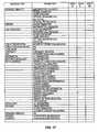
- FIG. 17is a table diagram of a message table used in the signaling processor of FIG. 8 .
- Telecommunication systemshave a number of communication devices in local exchange and interexchange environments that interact to provide call services to customers. Both traditional services and resources and intelligent network (IN) services and resources are used to process, route, or connect a call to a designated connection.
- Iintelligent network
- a callhas call signaling and user communications.
- the user communicationscontain the caller's information, such as a voice communication or data communication, and they are communicated over a connection.
- Call signalingcontains information that facilitates call processing, and it is communicated over a link.
- Call signalingfor example, contains information describing the called number and the calling number. Examples of call signaling are standardized signaling, such as signaling system #7 (SS7), C7, integrated services digital network (ISDN), and digital private network signaling system (DPNSS), which are based on ITU recommendation Q.933.
- SS7signaling system #7
- C7C7
- ISDNintegrated services digital network
- DPNSdigital private network signaling system
- a callcan be transported to or from a communication device.
- a communication devicecan be, for example, customer premises equipment (CPE), a service platform, a switch, or any other device capable of initiating, handling, or terminating a call.
- Customer premises equipmentcan be, for example, a telephone, a computer, a facsimile machine, or a private branch exchange.
- a service platformcan be, for example, a service platform or any other enhanced platform that is capable of processing calls.
- CPEcan be connected to a switch using a time division multiplex (TDM) format, such as super frame (SF) or extended superframe (ESF).
- TDMtime division multiplex
- SFsuper frame
- ESFextended superframe
- communication devicessuch as telephones
- the connectiontypically carries analog signals over twisted pair wires.
- the remote digital terminalsprovide a digital interface between the telephones and a local switch by converting the analog signals from the telephones into a multiplexed digital signal to be transferred to the local switch.
- a common standard for the connection between the remote digital terminal and the local switchis provided in Bellcore Reference GR-TSY-000303 (GR-303).
- B-ISDNbroadband-integrated services digital network
- Broadband systemsprovide greater bandwidth than narrowband systems for calls, in addition to providing digital processing of the calls.
- B-ISDNprovides a communication device with a digital connection to a local switch or other device.
- the B-ISDN loopprovides more bandwidth and control than a convention local loop.
- the European implementation of B-ISDN and other broadband protocolscan also be used.
- Digital signal (DS) level communicationssuch as digital signal level 3 (DS3), digital signal level one (DS1), and digital signal level zero (DS0) are conventional circuit-based connections.
- European level four (E4), European level three (E3), European level one (E1), European level zero (E0), and other European equivalent circuit-based connectionsalso are used.
- High speed electrical/optical transmission protocolsalso are used by communications devices for switching and signaling.
- SONETsynchronous optical network
- SDHsynchronous digital hierarchy
- SONET and SDH protocolsdescribe the physical media and transmission protocols through which the communications take place.
- the SONET and SDH protocolsdefine a broadband frame structure for SONET and SDH communications signals. Multiple frames travel in the communication signals. Each frame consists of overhead and payload.
- the overheadcontains operations, administration, maintenance, and provisioning information, such as framing information, error correction information, and pointer information.
- the payloadcontains the user communications information that is carried in the frame by the communication signal.
- the payloadis comprised of payload components that are mapped into the frames. For example, user communications from a DS1, an E1, or an asynchronous transfer mode (ATM) connection may be mapped into the broadband frames.
- ATMasynchronous transfer mode
- SONETincludes optical transmission of optical carrier (OC) signals and electrical transmission of synchronous transport signals (STSs).
- SONET signalstransmit at a base rate of 51.84 Mega-bits per second (Mbps) for optical carrier level one (OC-1) and synchronous transport signal level one (STS-1).
- STS-3an STS level three
- OC-12OC level twelve
- STS-48STS level forty-eight
- OC-48OC level forty-eight
- SDHincludes transmission of optical synchronous transport module (STM O) signals and electrical synchronous transport module (STM E) signals.
- SDH signalstransmit at a base rate of 155.52 Mbps for synchronous transport module level one electrical and optical (STM-1 E/O). Also transmitted are multiples thereof, such as an STM level four electrical/optical (STM-4 E/O) at rates of 622.08 Mbps, an STM level sixteen electrical/optical (STM-16 E/O) at rates of 2,488.32 Mbps, and fractions thereof, such as a tributary unit group (TUG) at a rate of 6.912 Mbps.
- STM Ooptical synchronous transport module
- STM Eelectrical synchronous transport module
- SDH signalstransmit at a base rate of 155.52 Mbps for synchronous transport module level one electrical and optical (STM-1 E/O). Also transmitted are multiples thereof, such as an STM level four electrical/optical (STM-4 E/O) at rates of 622.08 Mbps, an STM
- ATMis one technology that is being used in conjunction with SONET and SDH to provide broadband call switching and call transport for telecommunication services.
- ATMis a protocol that describes communication of user communications in ATM cells. Because cells are used in the protocol, calls can be transported on demand for connection-oriented traffic or connectionless-oriented traffic, constant-bit traffic or variable-bit traffic, and between equipment that either requires timing or does not require timing.
- Some ATM systemshandle calls over switched virtual paths (SVPs) and switched virtual circuits (SVCs).
- SVPsswitched virtual paths
- SVCsswitched virtual circuits
- the virtual nature of ATMallows multiple communication devices to use a physical communication line at different times. This type of virtual connection more efficiently uses bandwidth, and thereby provides more cost efficient transport for customer calls, than permanent virtual circuits (PVCs) or other dedicated circuits.
- PVCspermanent virtual circuits
- the ATM systemis able to connect a caller from an origination point to a destination point by selecting a connection from the origination point to the destination point.
- the connectioncontains a virtual path (VP) and a virtual channel (VC).
- a VCis a logical connection between two end points for the transfer of ATM cells.
- a VPis a logical combination of VCs.
- the ATM systemdesignates the selected connection by specifying a virtual path identifier (VPI) that identifies the selected VP and a virtual channel identifier (VCI) that identifies the selected VC within the selected VP. Because many ATM connections are uni-directional, bi-directional communications in an ATM system usually require companion VPIs/VCIs.
- An ATM systemmay be configured to transmit ATM cells over a SONET broadband system or an SDH broadband system.
- the ATM cellsare mapped into the payload of the SONET frames or the SDH frames and transported over a broadband path, such as a SONET pipe or an SDH pipe.
- a broadband pathsuch as a SONET pipe or an SDH pipe.
- SONET and SDH systemsare configured in a ring topology that can provide redundant and alternate transmission paths for calls.
- the present inventionefficiently and easily provides connections and switching for switches and other communication devices over a broadband system.
- the present inventionprovides call connections by using ATM over a SONET broadband system or an SDH broadband system.
- the ATM systemprovides robust switching functions at an affordable cost.
- FIG. 1illustrates the broadband system 102 of the present invention.
- the broadband system 102concentrates and switches telecommunication call traffic between networks, switches, and elements of the broadband system.
- the broadband system 102allows switches and other communication devices to connect to each other without a direct connection between each switch and communication device.
- the broadband system 102may be, for example, a broadband metropolitan area network (BMAN).
- BMANbroadband metropolitan area network
- the broadband system 102comprises a signaling processor 104 and a plurality of broadband interfaces, such as a first broadband interface 106 , a second broadband interface 108 , a third broadband interface 110 , a fourth broadband interface 112 , a fifth broadband interface 114 , and a sixth broadband interface 116 . It will be appreciated that the broadband system 102 may have a greater or a fewer number of broadband interfaces.
- the broadband interfaces 106 , 108 , 110 , 112 , 114 , and 116are connected through a series of connections.
- the first broadband interface 106is connected to the second broadband interface 108 through a connection 118 .
- the second broadband interface 108is connected to the third broadband interface 110 through a connection 120 .
- the third broadband interface 110is connected to the fourth broadband interface 112 through a connection 122 .
- the fourth broadband interface 112is connected to the fifth broadband interface 114 through a connection 124 .
- the fifth broadband interface 114is connected to the sixth broadband interface 116 through a connection 126 .
- the sixth broadband interface 116is connected to the first broadband interface 106 through a connection 128 .
- the broadband interfaces 106 , 108 , 110 , 112 , 114 , and 116 and the connections 118 , 129 , 122 , 124 , 126 , and 128form a broadband ring.
- Each of the broadband interfaces 106 , 108 , 110 , 112 , 114 , and 116is linked to the signaling processor 104 through a link 130 , 132 , 134 , 136 , 138 , and 140 , respectively.
- any broadband interfacemay reach any other broadband interface in the broadband ring.
- the first broadband interface 106may connect to the fifth broadband interface 114 by connecting through the connection 128 , the sixth broadband interface 116 , and the connection 126 .
- connections 118 , 120 , 122 , 124 , 126 , and 128are ATM VPIs/VCIs connections that are provisioned over SONET or SDH broadband paths.
- the connections 118 , 120 , 122 , 124 , 126 , and 128may be VPIs/VCIs that are provisioned over OC-48 pipes.
- the broadband interfaces 106 , 108 , 110 , 112 , 114 , and 116 and the SONET or SDH broadband paths containing the provisioned virtual connections 118 , 120 , 122 , 124 , 126 , and 128form a SONET ring or an SDH ring.
- Each of the broadband interfaces 106 , 108 , 110 , 112 , 114 , and 116may be connected to a switch or to another communication device.
- the first broadband interface 108is connected to a first communication device 142 through a connection 144 .
- the second broadband interface 108is connected to a second communication device 146 through a connection 148 .
- the third broadband interface 110is connected to a first interexchange carrier (IXC) 150 through a connection 152 .
- the fourth broadband interface 112is connected to an incumbent local exchange carrier (ILEC) 154 through a connection 156 .
- the fifth broadband interface 114is connected to a competitive local exchange carrier (CLEC) 158 through a connection 160 .
- VECcompetitive local exchange carrier
- the sixth broadband interface 116is connected to a second IXC 162 through a connection 164 .
- the signaling processor 104is linked to the first communication device 142 through a link 166 , to the second communication device 144 through a link 168 , to the first IXC 150 through a link 170 , to the ILEC 154 through a link 172 , to the CLEC 158 through a link 174 , and to the second IXC 162 through a link 176 .
- the connections 144 , 148 , 156 , and 160may be any connection that carries circuit-based traffic. Typically, these are time division multiplex (TDM) connections, such as DS3 or DS1 connections. Typically, the common DS0 used for traditional voice calls is embedded within the DS3 or DS1.
- the connections 152 and 164may be either TDM connections, such as DS3 or DS1 connections, or broadband path connections, such as OC-48 connections that carry ATM traffic.
- Connectionsare used to transport user communications and other device information between communication devices and between the elements and devices of the broadband system 102 .
- the term “connection” as used hereinmeans the transmission media used to carry user communications between the elements of the broadband system 102 or between the broadband system 102 and other communication devices and elements.
- a connectioncould carry a user's voice, computer data, or other communication device data.
- a connectioncan be associated with either in-band communications or out-of-band communications.
- Linksare used to transport call signaling and control messages.
- the term “link” as used hereinmeans a transmission media used to carry call signaling and control messages.
- a linkwould carry call signaling or a device control message containing device instructions and data.
- a linkcan carry, for example, out-of-band signaling such as SS7, C7, ISDN, B-ISDN, GR-303, local area network (LAN), or data bus call signaling.
- a linkcan be, for example, an AAL5 data link, UDP/IP, ethernet, or DS0 over T1.
- a linkas shown in the figures, can represent a single physical link or multiple links, such as one link or a combination of links of ISDN, SS7, TCP/IP, or some other data link.
- control messagemeans a control or signaling message, a control or signaling instruction, or a control or signaling signal, whether proprietary or standardized, that conveys information from one point to another.
- STPsignal transfer point
- the signaling processor 104is a signaling platform that can receive and process signaling. Based on the processed signaling, the signaling processor 104 selects processing options, connections, or resources for the user communications and generates and transmits control messages that identify the communication device, processing option, service, or resource that is to be used. The signaling processor 104 also selects virtual connections and circuit-based connections for call routing and generates and transports control messages that identify the selected connections. The signaling processor 104 can process various forms of signaling, including ISDN, SS7, and C7. A preferred signaling processor is discussed in detail below.
- the broadband interfaces 106 , 108 , 110 , 112 , 114 , and 116transport telecommunication traffic between circuit-based connections and virtual connections, between circuit-based connections and other circuit-based connections, or between virtual connections and other virtual connections.
- the broadband interfaces 106 , 108 , 110 , 112 , 114 , and 116place telecommunication traffic onto the broadband paths of the broadband system 102 and take telecommunication traffic from the broadband paths of the broadband system.
- the broadband interfaces 106 , 108 , 110 , 112 , 114 , and 116receive telecommunication traffic from circuit-based systems and transfer telecommunication traffic to circuit-based systems.
- the broadband interfaces 106 , 108 , 110 , 112 , 114 , and 116provide switching and intelligent network functions for calls.
- the broadband interfaces 106 , 108 , 110 , 112 , 114 , and 116together with the signaling processor 104 , connect calls from one communication device to another communication device.
- the communication devices 142 and 146each comprise CPE, a service platform, a switch, a remote digital terminal, or any other device capable of initiating, handling, or terminating a call.
- CPEcan be, for example, a telephone, a computer, a facsimile machine, or a private branch exchange.
- a service platformcan be, for example, a service platform or any other enhanced platform that is capable of processing calls.
- a remote digital terminalis a device that concentrates analog twisted pairs from telephones and other like devices and converts the analog signals to a digital format known as GR-303.
- the first and second IXCs 150 and 162comprise communication devices that can transport, receive, and handle calls.
- the first and second IXCs 150 and 162may be connected to other IXCs, local exchange carriers (LECs), or other communication devices.
- LECslocal exchange carriers
- the ILEC 154 and the CLEC 158each comprise switches that transport, receive, and handle calls.
- the ILEC 154is an established local network.
- the CLEC 158is a newer local network that is allowed to compete with the established local network.
- the ILEC 154 and the CLEC 158may be, for example, class 4 tandem switches, class 5 switches, or class 4 / 5 switches.
- the switches shown on FIG. 1are well known circuit switches with examples being the Nortel DMS-250 or the Lucent 5ESS.
- the system of FIG. 1operates as follows for a call that is transported between the CLEC 158 and the ILEC 154 through a SONET ring.
- the CLEC 158transports call signaling to the signaling processor 104 over the link 174 and transports user communications in a TDM format to the fifth broadband interface 114 over the connection 160 .
- the signaling processor 104receives the call signaling and processes the call signaling to determine connections for the call.
- the signaling processor 104selects a first connection 124 and a second connection 156 .
- the selected first connection 124is a SONET/ATM connection having an ATM VPI/VCI virtual connection that is provisioned over a SONET OC level broadband path on the SONET ring between the fourth broadband interface 112 and the fifth broadband interface 114 .
- the selected first connectionmay be a VPI/VCI provisioned over an OC-48 span.
- the selected second connection 156is a TDM connection.
- the signaling processor 104transports a control message over the link 138 to the fifth broadband interface 114 identifying the selected first connection 124 .
- the signaling processor 104also transmits a control message over the link 136 to the fourth broadband interface 112 identifying the selected second connection 156 .
- the fifth broadband interface 114receives the control message from the signaling processor 104 and the user communications from the CLEC 158 .
- the fifth broadband interface 114converts the TDM formatted user communications to ATM cells that identify the selected first connection 124 and maps the ATM cells to SONET frames.
- the fifth broadband interface 114places the SONET frames on the virtual connection of the designated SONET path for the selected first connection 124 so that they are transported to the fourth broadband interface 112 over the SONET ring.
- the fourth broadband interface 112receives the control message from the signaling processor 104 and receives the SONET frames over the selected first connection 124 .
- the fourth broadband interface 112drops the SONET frames from the SONET ring and then maps the SONET frames to the ATM cells.
- the fourth broadband interface 112converts the ATM cells to TDM formatted user communications and transports the user communications to the ILEC 154 over the selected second connection 156 .
- a callmay be connected from the ILEC 154 and to the CLEC 158 in the same manner.
- a callmay be connected between the ILEC 154 and the first IXC 105 , the ILEC 154 and the second communication device 146 , or the ILEC 154 and the first communication device 142 .
- a callmay be connected between any of the elements in the broadband system 102 .
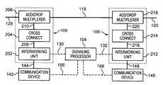
- FIG. 2illustrates the components of the first broadband interface 106 and the second broadband interface 108 .
- the first broadband interface 106 and the second broadband interface 108are representative of broadband interfaces in the broadband system 102 .
- the first broadband interface 106is comprised of a first interworking unit 202 , a first cross connect 204 , and a first ring terminal, such as a first add/drop multiplexer (ADM) 206 .
- the first cross connect 204is connected to the first interworking unit 202 through a connection 208 and to the first ADM 206 through a connection 210 .
- the first interworking unit 202interworks traffic between various protocols. Preferably, the first interworking unit 202 interworks between ATM traffic and non-ATM traffic.
- the first interworking unit 202operates in accordance with control messages received from the signaling processor 104 over the link 130 . These control messages are typically provided on a call-by-call basis and typically identify an assignment between a DS0 and a VPI/VCI for which user communications are interworked.
- the first interworking unit 202converts TDM formatted user communications to ATM cells that identify virtual connections selected by the signaling processor 104 .
- the first interworking unit 202maps ATM cells to broadband frames, such as SONET frames.
- the first interworking unit 202also maps broadband frames, such as SONET frames, to ATM cells.
- the first interworking unit 202converts the ATM cells to TDM formatted user communications.
- the first interworking unit 202may transport control messages which may include data to the signaling processor 104 .
- the first interworking unit 202is operational to implement digital signal processing as instructed in the control messages.
- digital signal processingis echo cancellation or continuity testing.
- a preferred embodiment of the first interworking unit 202is discussed in detail below.
- the first cross connect 204is any device, such as an ATM cross connect, that provisions virtual connections over broadband paths, such as ATM connections over SONET paths in a SONET ring.
- the first cross connect 204provides a plurality of ATM virtual connections between the first ADM 206 and the first interworking unit 202 .
- virtual connectionsare designated by the VPI/VCI in the cell header.
- the first cross connect 204is configured to accept ATM cells from, and transport ATM cells to, the first interworking unit 202 and to provide a plurality of VPI/VCI connections to the first ADM 206 .
- VCIsare used to differentiate individual calls on the VPI between the first cross connect 204 and the first ADM 206 and to identify the destination or handling point of the call.
- VPI/VCI “A”may be provisioned from the first interworking unit 202 , through the first cross connect 204 , through the first ADM 206 , and “destined” for an interworking unit connected to a cross connect in the second broadband interface 108 that is associated with the second communication device 146 .
- VPI/VCI “B”may be provisioned from the first interworking unit 202 , through the first cross connect 204 , through the first ADM 206 , and “destined” for an interworking unit connected to a cross connect in the fourth broadband interface 112 that is associated with the ILEC 154 .
- An example of an ATM cross connectis the NEC Model 20 .
- the first cross connect 204provisions the connections from the first interworking unit 202 , through the first ADM 206 , and to another cross connect and from another cross connect, through the first ADM, and to the first interworking unit.
- the first cross connect 204receives SONET frames containing mapped ATM cells from the first ADM 206 and cross connects the SONET frames on the connection to the first interworking unit 202 .
- the first cross connect 204receives SONET frames containing mapped ATM cells from the first interworking unit 202 and cross connects the SONET frames on the designated VPI/VCI virtual connection to the first ADM 206 .
- the first ADM 206adds traffic to the broadband paths of the broadband ring for the connections 118 and 128 or drops traffic from the broadband paths for the connections.
- the first ADM 206may add or drop traffic that is transported at levels extending from the DS1 level to the OC level or the STS level and to equivalent standards.
- the broadband paths for connections leading to and from the first ADM 206are provisioned by the first ADM 206 as, for example, SONET paths to all other communication devices in the broadband system 102 .
- a SONET pathis provisioned between the first ADM 206 in the first broadband interface 106 and an ADM in the second broadband interface 108 to carry traffic for the virtual connection for the connection 118 .
- Another SONET pathis provisioned between the first ADM 206 in the first broadband interface 106 and an ADM in the sixth broadband interface 116 to carry traffic for the virtual connection for the connection 128 . (See FIG. 1.)
- the second broadband interface 108is comprised of a second interworking unit 212 , a second cross connect 214 , and a second ring terminal, such as a second add/drop multiplexer (ADM) 216 .
- the second cross connect 214is connected to the second interworking unit 212 through a connection 218 and to the second ADM 206 through a connection 220 .
- the second interworking unit 212interworks traffic between various protocols. Preferably, the second interworking unit 212 interworks between ATM traffic and non-ATM traffic.
- the second interworking unit 212operates in accordance with control messages received from the signaling processor 104 over the link 132 . These control messages are typically provided on a call-by-call basis and typically identify an assignment between a DS0 and a VPI/VCI for which user communications are interworked.
- the second interworking unit 212converts TDM formatted user communications to ATM cells that identify virtual connections selected by the signaling processor 104 .
- the second interworking unit 212maps ATM cells to broadband frames, such as SONET frames.
- the second interworking unit 212also maps broadband frames, such as SONET frames, to ATM cells.
- the second interworking unit 212converts ATM cells to TDM formatted user communications.
- the second interworking unit 212may transport control messages which may include data to the signaling processor 104 .
- the second interworking unit 212is operational to implement digital signal processing as instructed in the control messages.
- digital signal processingis echo cancellation or continuity testing.
- a preferred embodiment of the second interworking unit 212is discussed in detail below.
- the second cross connect 214is any device, such as an ATM cross connect, that provisions virtual connections over broadband paths, such as ATM connections over a SONET ring.
- the second cross connect 214provides a plurality of ATM virtual connections between the second ADM 216 and the second interworking unit 212 .
- virtual connectionsare designated by the VPI/VCI in the cell header.
- the second cross connect 214is configured to accept ATM cells from, and transport ATM cells to, the second interworking unit 212 and to provide a plurality of VPI/VCI connections to the second ADM 216 .
- VCIsare used to differentiate individual calls on the VPI between the second ADM 216 and the second interworking unit 212 and to identify the destination or handling point of the call.
- VPI/VCI “A”may be provisioned from the second interworking unit 212 , through the second cross connect 214 , through the second ADM 216 , and “destined” for an interworking unit connected to a cross connect in the first broadband interface 106 that is associated with the first communication device 142 .
- VPI/VCI “B”may be provisioned from the second interworking unit 212 , through the second cross connect 214 , through the second ADM 216 , and “destined” for an interworking unit connected to a cross connect in the fourth broadband interface 112 that is associated with the ILEC 154 .
- An example of an ATM cross connectis the NEC Model 20.
- the second cross connect 214provisions the virtual connections from the second interworking unit 212 , through the second ADM 216 , and to other cross connects and from other cross connects, through the the ADM, and to the second interworking unit.
- the second cross connect 214receives SONET frames containing mapped ATM cells from the second ADM 216 and cross connects the SONET frames on the connection to the second interworking unit 212 .
- the second cross connect 214receives SONET frames containing mapped ATM cells from the second interworking unit 212 and cross connects the SONET frames on the designated virtual connection for the connection to the second ADM 216 .
- the second ADM 216adds traffic to the broadband paths of the broadband ring for the connections 118 and 120 or drops traffic from the broadband paths for the connections.
- the second ADM 216may add or drop traffic that is transported at levels extending from the DS1 level to the OC level or the STS level and equivalent standards.
- the broadband paths for connections leading to and from the second ADM 216are provisioned by the second ADM 216 as, for example, SONET paths to all other communication devices in the broadband system 102 .
- a SONET pathis provisioned between the second ADM 216 in the second broadband interface 108 and the first ADM 206 in the first broadband interface 106 to carry traffic for the virtual connection for the connection 118 .
- Another SONET pathis provisioned between the second ADM 216 in the second broadband interface 108 and an ADM in the sixth broadband interface 116 to carry traffic for the virtual connection for the connection 120 . (See FIG. 1.)
- a broadband path in a SONET systemis identified by a SONET OC level or STS level path.
- a virtual connectionis identified by an ATM VPI/VCI or companion ATM VPIs/VCIs.
- This combination of the provisioned virtual connection in the provisioned broadband pathshall be referred to herein as the ATM connection over the SONET path or as the virtual connection of the broadband path.
- the provisioned VPI/VCI between the first interworking unit 202 and the second interworking unit 212 , through the first cross connect 204 and the second cross connect 214 , which extends through the provisioned broadband path of the SONET ring between the first ADM 206 and the second ADM 216is referred to herein as the virtual connection over the broadband path for the connection 118 or as the ATM connection of the SONET ring for the connection 118 .
- a terminal multiplexer or an access multiplexermay be used instead of the add/drop multiplexer of the preferred system described above.
- the first broadband interface 106 and the second broadband interface 108 of FIG. 2operate as follows when the first communication device 142 transports a call to the second communication device 146 in a SONET broadband system 102 .
- the operation of the first broadband interface 106 and the second broadband interface 108are representative of the other broadband interfaces 110 , 112 , 114 , and 116 .
- SONET pathsare provisioned from each broadband interface 106 , 108 , 110 , 112 , 114 , and 116 to every other broadband interface in the broadband network 102 .
- the fifth broadband interface 114will have a SONET path provisioned to every other broadband interface 106 , 108 , 110 , 112 , and 116 . It will be appreciated that this forms a flat architecture between the broadband interfaces 106 , 108 , 110 , 112 , 114 , and 116 which is implemented over the SONET ring.
- the SONET pathsare provisioned between the ADMs in each broadband interface 106 , 108 , 110 , 112 , 114 , and 116 , such as between the first ADM 206 and the second ADM 216 .
- ATM connectionsare provisioned between the cross connects of each broadband interface 106 , 108 , 110 , 112 , 114 , and 116 to the cross connects in each other broadband interface and to the associated interworking units.
- the first cross connect 204 in the first broadband interface 106uses the SONET paths provided by the ADM 206 to provision an ATM connection from the first interworking unit 202 through the second cross connect 214 in the second broadband interface 108 to the second interworking unit 212 .
- the interworking units of each of the broadband interfaces 106 , 108 , 110 , 112 , 114 , and 116have a provisioned ATM connection over the SONET ring to each of the interworking units in the other broadband interfaces.
- the first interworking unit 202 in the first broadband interface 106has a provisioned ATM connection over the SONET ring to each of the interworking units in the other broadband interfaces 108 , 110 , 112 , 114 , and 116 .
- the first interworking unit 202 in the first broadband interface 106has a provisioned ATM connection over the SONET ring to the second interworking unit 212 in the second broadband interface 108 .
- an interworking unitplaces the ATM cells on the selected connection, and the ATM cells are transported in the broadband frames to the receiving interworking unit. It will be appreciated that ATM connections may be provisioned over the SONET ring prior to a call, and that ATM connections may be reprovisioned over the SONET ring during or after a call.
- ATM cellsthat identify the VPI/VCI of the selected connection. This allows ATM capable communication devices to transport calls to, and receive calls from, other ATM capable communication devices.
- the ATM cellsare then mapped into SONET frames to be transported and received over the SONET paths. Typically, the ATM cells are mapped to an OC-3 level or an STS-3c level communication. It should be noted that, for clarity, ATM cells that are mapped to SONET frames may be referred to below as ATM cells, without the reference to the SONET frame mapping.
- ATM cellsare mapped to and from SONET frames at the first and second interworking units 202 and 212 .
- the first communication device 142transports the call signaling to the signaling processor 104 over the link 166 in an appropriate format, such as SS7.
- the first communication device 142transports the user communications to the first interworking unit 202 over the connection 144 in a communication format, such as a TDM format over a DS0 embedded in a DS3.
- the signaling processor 104receives the call signaling and processes the call signaling to determine connections for the call.
- the signaling processor 104selects a first connection 118 over which the ATM formatted user communications will be transported from the first broadband interface 106 .
- the selected first connection 118is an ATM connection over a SONET path, such as a VPI/VCI in an OC-48 pipe.
- the signaling processor 104transports a control message over the link 130 to the first interworking unit 202 .
- the control messageidentifies the selected first connection 118 .
- the signaling processor 104also processes the call signaling to determine a second connection 148 for the call over which the second interworking unit 212 will transport TDM formatted user communications to the second communication device 146 .
- the selected second connection 148is a TDM connection, such as a DS0 embedded in a DS3.
- the signaling processor 104transports a control message over the link 132 to the second interworking unit 212 .
- the control messageidentifies the selected second connection 148 .
- the first interworking unit 202receives the control message from the signaling processor 104 and the user communications from the first communication device 142 .
- the first interworking unit 202interworks the TDM formatted user communications to ATM cells that identify the selected VPI/VCI of the first connection 118 .
- the ATM cellsare mapped to SONET frames for the requisite OC level or STS level communication.
- the first interworking unit 202then transports the ATM cells in the SONET frames to the first cross connect 204 over a connection 208 .
- the connectionis an OC-3.
- the first cross connect 204receives the SONET frames containing the ATM cells.
- the first cross connect 204removes the ATM cells from the SONET frames and cross connects the ATM cells through the ATM fabric to the appropriate provisioned virtual connection for the selected first connection 118 .
- the first cross connect 204maps the ATM cells back into SONET frames at the output of the first cross connect.
- the SONET frames containing the ATM cellsare transported to the first ADM 206 over a provisioned path in the connection 210 for the VPI/VCI of the selected first connection 118 .
- the connection 210preferably is an OC level or an STS level connection, such as an OC-3. It can be seen that cells are transported to the correct connection when the correct VPI/VCI is selected.
- the first ADM 206receives the SONET frames containing the ATM cells from the first cross connect 204 over the connection 210 .
- the first ADM 206adds the frames on the provisioned broadband path on the SONET ring that has the corresponding provisioned VPI/VCI of the selected first connection 118 .
- the SONET framesare transported over the SONET ring on, for example, an OC-48 to the second broadband interface 108 .
- the second ADM 216receives the SONET frames containing the ATM cells over the selected first connection 118 of the SONET ring.
- the second ADM 216drops the SONET frames containing the ATM cells from the SONET ring to the second cross connect 214 .
- the second cross connect 214receives the SONET frames over the connection 220 .
- the second cross connect 214cross connects the SONET frames containing the ATM cells to the second interworking unit 212 over the provisioned path in the connection 218 that corresponds to the VPI/VCI in the ATM cells.
- the second interworking unit 212receives the SONET frames from the second cross connect 214 and the control message from the signaling processor 104 .
- the second interworking unit 212maps the SONET frames to the ATM cells.
- the second interworking unit 212converts the ATM cells to TDM formatted user communications and transports the TDM formatted user communications to the second communication device 146 over the selected second connection 148 .
- a callmay be connected from the second communication device 146 to the first communication device 142 .
- the process for the connection and the transport of the user communicationsis the same as described above, except that the second broadband interface 108 transports the user communications as ATM cells mapped in SONET frames and the first broadband interface 106 receives the user communications as ATM cells mapped in the SONET frames.
- ATM cellsmay be mapped to STM-1 electrical/optical (E/O) frames in the SDH system instead of analogous STS-3c/OC-3 frames in a SONET system.
- ATM cells and lower SDH level communicationsmay be multiplexed or mapped up to STM-12 E/O communications in the SDH system instead of analogous STS-48/OC-48 communications in a SONET system.
- the functions of the signaling processor 104 , the first interworking unit 202 , the first cross connect 204 , and the first ADM 206provide switching-type functions for ATM traffic being transported to communication devices in the SONET ring from the first broadband interface 106 .
- the functions of the signaling processor 104 , the second interworking unit 212 , the second cross connect 214 , and the second ADM 216provide switching-type functions for traffic being transported to communication devices, such as switches, from the SONET ring.
- These switching functionsgive the broadband system 102 the ability to connect and switch calls to any location in the broadband system 102 . This allows the broadband system to complete such functions as local number portability so that a telephone service customer can switch services from, for example, the ILEC 154 to the CLEC 158 and keep the same local telephone number. Other services, including intelligent network services, also may be provided.
- the present invention as explained abovemay be adapted for use with other devices or with fewer devices.
- the first broadband interface 106may be adapted to be used without the cross connect 204 .
- some switching functionalitymay be eliminated because broadband paths then would be provisioned to the first interworking unit 202 , and the first interworking unit would have to select the broadband path.
- Multiple SONET pathsmay be provisioned from the first interworking unit 202 to each call destination.
- the broadband interface 302may have multiple interworking units or cross connects.
- a cross connect 304may be connected to a first interworking unit 306 and to a second interworking unit 308 , in addition to an ADM 310 .
- a signaling processor 312processes call signaling and determines connections and processing for the components of the broadband interface 302 .
- the first and second interworking units 306 and 308may be in the same proximate location or in different proximate locations.
- the cross connect 304 or other componentsmay be connected to another cross connect or to a gateway (not shown).
- the broadband system 102 Bmay use an STP 404 .
- the broadband system 102 Bmay be configured so that a plurality of broadband interfaces are each connected to its own signaling processor.
- the broadband system 102 Bhas a first broadband interface 404 linked to a first signaling processor 406 , a second broadband interface 408 linked to a second signaling processor 410 , a third broadband interface 412 linked to a third signaling processor 414 , a fourth broadband interface 416 linked to a fourth signaling processor 418 , a fifth broadband interface 420 linked to a fifth signaling processor 422 , and a sixth broadband interface 424 linked to a sixth signaling processor 426 .
- Each of the signaling processors 406 , 410 , 414 , 418 , 422 , and 426are linked to the STP 402 . For clarity, the links and the connections are not referenced.
- a broadband interfacemay be connected to a class 4 switch, a class 5 switch, or a class 4 / 5 switch. These switches may, in turn, be connected to other class 4 , class 5 , or class 4 / 5 switches.
- the broadband system and broadband interfacesmay be used to connect and process calls in a local architecture or in an interexchange architecture.
- the broadband system and broadband interfacesmay be used to connect and process calls in facility based and non-facility based traffic.
- the broadband interfacesmay connect to in-band signaling communication devices as well as the out-of-band signaling communication devices.
- the ATM Interworking UnitThe ATM Interworking Unit
- FIG. 5shows one embodiment of an interworking unit which is an ATM interworking unit 502 suitable for the present invention for use with a SONET system, but other interworking units that support the requirements of the invention are also applicable.
- the ATM interworking unit 502may receive and transmit in-band and out-of-band calls.
- the ATM interworking unit 502has a control interface 504 , an OCN/STS-N interface 506 , a DS3 interface 508 , a DS1 interface 510 , a DS0 interface 512 , a signal processor 514 , an ATM adaptation layer (AAL) 516 , an OC-M/STS-M interface 518 , and an ISDN/GR-303 interface 520 .
- AALATM adaptation layer
- OC-M/STS-M interface 518an ISDN/GR-303 interface 520 .
- the control interface 502accepts control messages from the signaling processor 522 .
- the control interface 504identifies DS0 connections and virtual connection assignments in the control messages from the signaling processor 522 . These assignments are provided to the AAL 516 for implementation.
- the OC-N/STS-N interface 506 , the DS3 interface 508 , the DS1 interface 510 , the DS0 interface 512 , and the ISDN/GR-303 interface 520each can accept calls, including user communications, from a communication device 524 .
- the OC-M/STS-M interface 518can accept calls, including user communications, from a communication device 526 .
- the OC-N/STS-N interface 506accepts OC-N formatted calls and STS-N formatted calls and converts the calls from the OC-N or STS-N formats to the DS3 format.
- the DS3 interface 508accepts calls in the DS3 format and converts the calls to the DS1 format.
- the DS3 interface 508can accept DS3s from the OC-N/STS-N interface 506 or from an external connection.
- the DS1 interface 510accepts the calls in the DS1 format and converts the calls to the DS0 format.
- the DS1 interface 510can accept DS1s from the DS3 interface 508 or from an external connection.
- the DS0 interface 512accepts calls in the DS0 format and provides an interface to the AAL 516 .
- the ISDN/GR-303 interface 520accepts calls in either the ISDN format or the GR-303 format and converts the calls to the DS0 format.
- each interfacemay transmit signals in like manner to the communication device 524 .
- the OC-M/STS-M interface 518is operational to accept ATM cells from the AAL 516 and to transmit the ATM cells over the connection to the communication device 526 .
- the OC-M/STS-M interface 518may also accept ATM cells in the OC or STS format and transmit them to the AAL 516 .
- the AAL 516comprises both a convergence sublayer and a segmentation and reassembly (SAR) sublayer.
- the AAL 516is operational to accept communication device information in the DS0 format from the DS0 interface 512 and to convert the communication device information into ATM cells.
- AALsare known in the art and information about AALs is provided by International Telecommunications Union (ITU) document I.363, which is incorporated fully herein by reference.
- ITUInternational Telecommunications Union
- An AAL for voice callsis described in U.S. patent application Ser. No. 08/395,745, which was filed on Feb. 28, 1995, and entitled “Cell Processing for Voice Transmission,” and which is incorporated herein by reference.
- the AAL 516obtains from the control interface 504 the virtual path identifier (VPI) and the virtual channel identifier (VCI) for each DS0 for each call connection. The AAL 516 also obtains the identity of the DS0 for each call (or the DS0s for an N ⁇ 64 call). The AAL 516 then transfers the communication device information between the identified DS0 and the identified ATM virtual connection. An acknowledgment that the assignments have been implemented may be sent to the signaling processor 522 if desired. Calls with multiple 64 Kilo-bits per second (Kbps) DS0 s are known as N ⁇ 64 calls. If desired, the AAL 516 can be configured to accept control messages through the control interface 504 for N ⁇ 64 calls.
- VPIvirtual path identifier
- VCIvirtual channel identifier
- the ATM interworking unit 502also handles calls in the opposite direction, that is, in the direction from the OC-M/STS-M interface 518 to the DS0 interface 512 , including calls exiting from the DS1 interface 510 , the DS3 interface 508 , the OC-N/STS-N interface 506 , and the ISDN/GR-303 interface 520 .
- the VPI/VCIhas been selected already and the traffic has been routed through the cross-connect (not shown).
- the AAL 516only needs to identify the pre-assigned DS0 for the selected VPI/VCI. This can be accomplished through a look-up table.
- the signaling processor 522can provide this DS0-VCI/VCI assignment through the control interface 504 to the AAL 516 .
- DS0 connectionsare bi-directional and ATM connections are typically uni-directional. As a result, two virtual connections in opposing directions typically will be required for each DS0.
- the cross-connectcan be provisioned with a second set of VPI/VCIs in the opposite direction as the original set of VPI/VCIs.
- ATM interworking multiplexerswould be configured to invoke automatically this second VPI/VCI to provide a bi-directional virtual connection to match the bi-directional DS0 on the call.
- a signal processor 514would be included either separately (as shown) or as a part of the DS0 interface 512 .
- the signaling processor 522would be configured to send control messages to the ATM interworking unit 502 to implement particular features on particular DS0 circuits.
- lookup tablesmay be used to implement particular features for particular circuits or VPIs/VCIs.
- FIG. 6shows another embodiment of an interworking unit which is an ATM interworking unit 602 suitable for the present invention.
- the ATM interworking unit 502may receive and transmit in-band and out-of-band calls.
- the ATM interworking unit 602is for use with an SDH system and has a control interface 604 , an STM-N electrical/optical (E/O) interface 606 , an E3 interface 608 , an E1 interface 610 , an E0 interface 612 , a signal processor 614 , an ATM adaptation layer (AAL) 616 , an STM-M electrical/optical (E/O) interface 618 , and a digital private network signaling system (DPNSS) interface 620 .
- Nrefers to an integer
- Mrefers to an integer.
- the control interface 604accepts control messages from the signaling processor 622 .
- the control interface 604identifies E0 connections and virtual connection assignments in the control messages from the signaling processor 622 . These assignments are provided to the AAL 616 for implementation.
- the STM-N E/O interface 606 , the E3 interface 608 , the E1 interface 610 , the E0 interface 612 , and the DPNSS interface 620each can accept calls, including user communications, from a second communication device 624 .
- the STM-M E/O interface 618can accept calls, including user communications, from a third communication device 626 .
- the STM-N E/O interface 606accepts STM-N electrical or optical formatted calls and converts the calls from the STM-N electrical or STM-N optical format to the E3 format.
- the E3 interface 608accepts calls in the E3 format and converts the calls to the E1 format.
- the E3 interface 608can accept E3s from the STM-N E/O interface 606 or from an external connection.
- the E1 interface 610accepts the calls in the E1 format and converts the calls to the E0 format.
- the E1 interface 610can accept E1s from the STM-N E/O interface 606 or the E3 interface 608 or from an external connection.
- the E0 interface 612accepts calls in the E0 format and provides an interface to the AAL 616 .
- the DPNSS interface 620accepts calls in the DPNSS format and converts the calls to the E0 format. In addition, each interface may transmit signals in a like manner to the communication device 624 .
- the STM-M E/O interface 618is operational to accept ATM cells from the AAL 616 and to transmit the ATM cells over the connection to the communication device 626 .
- the STM-M E/O interface 618may also accept ATM cells in the STM-M E/O format and transmit them to the AAL 616 .
- the AAL 616comprises both a convergence sublayer and a segmentation and reassembly (SAR) sublayer.
- the AAL 616is operational to accept communication device information in the E0 format from the E0 interface 612 and to convert the communication device information into ATM cells.
- the AAL 616obtains from the control interface 604 the virtual path identifier and the virtual channel identifier for each call connection. The AAL 616 also obtains the identity of each call. The AAL 616 then transfers the communication device information between the identified E0 and the identified ATM virtual connection. An acknowledgment that the assignments have been implemented may be sent back to the signaling processor 622 if desired. If desired, the AAL 616 can be configured to accept control messages through the control interface 604 for N ⁇ 64 calls.
- the ATM interworking unit 602also handles calls in the opposite direction, that is, in the direction from the STM-M E/O interface 618 to the E0 interface 612 , including calls exiting from the E1 interface 610 , the E3 interface 608 , the STM-N E/O interface 606 , and the DPNSS interface 620 .
- the VPI/VCIhas been selected already and the traffic has been routed through the cross-connect (not shown).
- the AAL 616only needs to identify the pre-assigned E0 for the selected VPI/VCI. This can be accomplished through a look-up table.
- the signaling processor 622can provide this VPI/VCI assignment through the control interface 604 to the AAL 616 .
- E0 connectionsare bi-directional and ATM connections typically are uni-directional. As a result, two virtual connections in opposing directions typically will be required for each E0.
- the cross-connectcan be provisioned with a second set of VPI/VCIs in the opposite direction as the original set of VPI/VCIs.
- ATM interworking multiplexerswould be configured to automatically invoke this second VPI/VCI to provide a bi-directional virtual connection to match the bi-directional E0 on the call.
- a signal processor 614would be included either separately (as shown) or as a part of the E0 interface 612 .
- the signaling processor 622would be configured to send control messages to the ATM interworking unit 602 to implement particular features on particular circuits.
- lookup tablesmay be used to implement particular features for particular circuits or VPIs/VCIs.
- the signaling processoris referred to as a call/connection manager (CCM), and it receives and processes telecommunications call signaling and control messages to select connections that establish communication paths for calls.
- CCMprocesses ISDN, GR-303, and SS7 signaling to select connections for a call.
- CCM processingis described in a U.S. patent application Ser. No. 08/754,349 which is entitled “Telecommunication System,” which is assigned to the same assignee as this patent application, and which is incorporated herein by reference.
- the CCMperforms many other functions in the context of call processing. It not only can control routing and select the actual connections, but it also can validate callers, control echo cancelers, generate billing information, invoke intelligent network functions, access remote databases, manage traffic, and balance network loads.
- the CCM described belowcan be adapted to operate in the above embodiments.
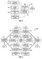
- FIG. 7depicts a version of the CCM.
- the CCM 702controls an ATM interworking unit, such as an ATM interworking multiplexer (mux) that performs interworking of DS0 s and VPI/VCIs.
- the CCMmay control other communications devices and connections in other embodiments.
- the CCM 702comprises a signaling platform 704 , a control platform 706 , and an application platform 708 .
- Each of the platforms 704 , 706 , and 708is coupled to the other platforms.
- the signaling platform 704is externally coupled to the signaling systems—in particular to SS7 signaling systems having a message transfer part (MTP), an ISDN user part (ISUP), a signaling connection control part (SCCP), an intelligent network application part (INAP), and a transaction capabilities application part (TCAP).
- MTPmessage transfer part
- ISUPISDN user part
- SCCPsignaling connection control part
- INAPintelligent network application part
- TCAPtransaction capabilities application part
- the control platform 706is externally coupled to an interworking unit control, an echo control, a resource control, billing, and operations.
- the signaling platform 704preferably is an SS7 platform that comprises MTP levels 1-3, ISUP, TCAP, SCCP, and INAP functionality and is operational to transmit and receive the SS7 messages.
- the ISUP, SCCP, INAP, and TCAP functionalityuse MTP to transmit and receive the SS7 messages. Together, this functionality is referred as an “SS7 stack,” and it is well known.
- the software required by one skilled in the art to configure an SS7 stackis commercially available, for example, from the Trillium company.
- the control platform 706is comprised of various external interfaces including an interworking unit interface, an echo interface, a resource control interface, a billing interface, and an operations interface.
- the interworking unit interfaceexchanges messages with at least one interworking unit. These messages comprise DS0 to VPI/VCI assignments, acknowledgments, and status information.
- the echo control interfaceexchanges messages with echo control systems. Messages exchanged with echo control systems might include instructions to enable or disable echo cancellation on particular DS0 s, acknowledgments, and status information.
- the resource control interfaceexchanges messages with external resources.
- resourcesare devices that implement continuity testing, encryption; compression, tone detection/transmission, voice detection, and voice messaging.
- the messages exchanged with resourcesare instructions to apply the resource to particular DS0 s, acknowledgments, and status information. For example, a message may instruct a continuity testing resource to provide a loopback or to send and detect a tone for a continuity test.
- the billing interfacetransfers pertinent billing information to a billing system. Typical billing information includes the parties to the call, time points for the call, and any special features applied to the call.
- the operations interfaceallows for the configuration and control of the CCM 702 .
- One skilled in the artwill appreciate how to produce the software for the interfaces in the control platform 706 .
- the application platform 708is functional to process signaling information from the signaling platform 704 in order to select connections. The identity of the selected connections are provided to the control platform 706 for the interworking unit interface.
- the application platform 708is responsible for validation, translation, routing, call control, exceptions, screening, and error handling. In addition to providing the control requirements for the interworking unit, the application platform 708 also provides requirements for echo control and resource control to the appropriate interface of the control platform 706 .
- the application platform 708generates signaling information for transmission by the signaling platform 704 .
- the signaling informationmight be ISUP, INAP, or TCAP messages to external network elements. Pertinent information for each call is stored in a call control block (CCB) for the call.
- the CCBcan be used for tracking and billing the call.
- the application platform 708operates in general accord with the Basic Call Model (BCM) defined by the ITU. An instance of the BCM is created to handle each call.
- the BCMincludes an originating process and a terminating process.
- the application platform 708includes a service switching function (SSF) that is used to invoke the service control function (SCF).
- SSFservice switching function
- SCFservice control function
- SCPservice control point
- SCFservice control point
- the SCFis queried with TCAP or INAP messages.
- the originating or terminating processeswill access remote databases with intelligent network (IN) functionality via the SSF function.
- Software requirements for the application platform 708can be produced in specification and description language (SDL) defined in ITU-T Z.100.
- SDLspecification and description language
- the SDLcan be converted into C code. Additional C and C++ code can be added as required to establish the environment.
- the CCM 702can be comprised of the above-described software loaded onto a computer.
- the computercan be an Integrated Micro Products (IMP) FT-Sparc 600 using the Solaris operating system and conventional database systems. It may be desirable to utilize the multi-threading capability of a Unix operating system.
- IMPIntegrated Micro Products
- the application platform 708processes signaling information to control numerous systems and facilitate call connections and services.
- the SS7 signalingis exchanged with external components through the signaling platform 704 , and control information is exchanged with external systems through the control platform 706 .
- the CCM 702is not integrated into a switch central processing unit (CPU) that is coupled to a switching matrix. Unlike an SCP, the CCM 702 is capable of processing ISUP messages independently of TCAP queries.
- Call processingtypically entails two aspects.
- First, an incoming or “originating” connectionis recognized by an originating call process. For example, the initial connection that a call uses to enter a network is the originating connection in that network.
- Second, an outgoing or “terminating” connectionis selected by a terminating call process. For example, the terminating connection is coupled to the originating connection in order to extend the call through the network.
- These two aspects of call processingare referred to as the originating side of the call and the terminating side of the call.
- FIG. 8depicts a data structure used by the application platform 708 to execute the BCM. This is accomplished through a series of tables that point to one another in various ways.
- the pointersare typically comprised of next function and next index designations.
- the next functionpoints to the next table, and the next index points to an entry or a range of entries in that table.
- the data structurehas a trunk circuit table 802 , a trunk group table 804 , an exception table 806 , an ANI table 808 , a called number table 810 , and a routing table 812 .
- the trunk circuit table 802contains information related to the connections. Typically, the connections are DS0 or ATM connections. Initially, the trunk circuit table 802 is used to retrieve information about the originating connection. Later, the table is used to retrieve information about the terminating connection. When the originating connection is being processed, the trunk group number in the trunk circuit table 802 points to the applicable trunk group for the originating connection in the trunk group table 804 .
- the trunk group table 804contains information related to the originating and terminating trunk groups. When the originating connection is being processed, the trunk group table 804 provides information relevant to the trunk group for the originating connection and typically points to the exception table 806 .
- the exception table 806is used to identify various exception conditions related to the call that may influence the routing or other handling of the call. Typically, the exception table 806 points to the ANI table 808 . Although, the exception table 806 may point directly to the trunk group table 804 , the called number table 810 , or the routing table 812 .
- the ANI table 808is used to identify any special characteristics related to the caller's number.
- the caller's numberis commonly known as automatic number identification (ANI).
- ANIautomatic number identification
- the ANI table 808typically points to the called number table 810 . Although, the ANI table 808 may point directly to the trunk group table 804 or the routing table 812 .
- the called number table 810is used to identify routing requirements based on the called number. This will be the case for standard telephone calls.
- the called number table 810typically points to the routing table 812 . Although, it may point to the trunk group table 804 .
- the routing table 812has information relating to the routing of the call for the various connections.
- the routing table 812is entered from a pointer in the exception table 806 , the ANI table 808 , or the called number table 810 .
- the routing table 812typically points to a trunk group in the trunk group table 804 .
- the trunk group table 804When the exception table 806 , the ANI table 808 , the called number table 810 , or the routing table 812 point to the trunk group table 804 , they effectively select the terminating trunk group. When the terminating connection is being processed, the trunk group number in the trunk group table 804 points to the trunk group that contains the applicable terminating connection in the trunk circuit table 804 .
- the terminating trunk circuitis used to extend the call.
- the trunk circuitis typically a VPI/VCI or a DS0.
- FIG. 9is an overlay of FIG. 8 .
- the tables from FIG. 8are present, but for clarity, their pointers have been omitted.
- FIG. 9illustrates additional tables that can be accessed from the tables of FIG. 8 . These include a CCM ID table 902 , a treatment table 904 , a query/response table 906 , and a message table 908 .
- the CCM ID table 902contains various CCM SS7 point codes. It can be accessed from the trunk group table 804 , and it points back to the trunk group table 804 .
- the treatment table 904identifies various special actions to be taken in the course of call processing. This 11 typically result in the transmission of a release message (REL) and a cause value.
- the treatment table 904can be accessed from the trunk circuit table 802 , the trunk group table 804 , the exception table 806 , the ANI table 808 , the called number table 810 , the routing table 812 , and the query/response table 906 .
- the query/response table 906has information used to invoke the SCF. It can be accessed by the trunk group table 804 , the exception table 806 , the ANI table 808 , the called number table 810 , and the routing table 812 . It points to the trunk group table 804 , the exception table 806 , the ANI table 808 , the called number table 810 , the routing table 812 , and the treatment table 904 .
- the message table 908is used to provide instructions for messages from the termination side of the call. It can be accessed by the trunk group table 804 and points to the trunk group table 804 .
- FIGS. 14-21depict examples of the various tables described above.
- FIG. 10depicts an example of the trunk circuit table. Initially, the trunk circuit table is used to access information about the originating circuit. Later in the processing, it is used to provide information about the terminating circuit. For originating circuit processing, the associated point code is used to enter the table. This is the point code of the switch or CCM associated with the originating circuit. For terminating circuit processing, the trunk group number is used to enter the table.
- the tablealso contains the circuit identification code (CIC).
- the CICidentifies the circuit which is typically a DS0 or a VPI/VCI.
- the inventionis capable of mapping the SS7 CICs to the ATM VPI/VCI. If the circuit is ATM, the virtual path (VP) and the virtual channel (VC) also can be used for identification.
- the group member numberis a numeric code that is used for terminating circuit selection.
- the hardware identifieridentifies the location of the hardware associated with the originating circuit.
- the echo canceler (EC) identification (ID) entryidentifies the echo canceler for the originating circuit.
- the remaining fieldsare dynamic in that they are filled during call processing.
- the echo control entryis filled based on three fields in signaling messages: the echo suppresser indicator in the IAM or CRM, the echo control device indicator in the ACM or CPM, and the information transfer capability in the IAM. This information is used to determine if echo control is required on the call.
- the satellite indicatoris filled with the satellite indicator in the IAM or CRM. It may be used to reject a call if too many satellites are used.
- the circuit statusindicates if the given circuit is idle, blocked, or not blocked.
- the circuit stateindicates the current state of the circuit, for example, active or transient.
- the time/dateindicates when the idle circuit went idle.
- FIG. 11depicts an example of the trunk group table.
- the trunk group number from the trunk circuit tableis used to key into the trunk table.
- Glare resolutionindicates how a glare situation is to be resolved. Glare is dual seizure of the same circuit. If the glare resolution entry is set to “even/odd,” the network element with the higher point code controls the even circuits, and the network element with the lower point code controls the odd circuits. If the glare resolution entry is set to “all,” the CCM controls all of the circuits. If the glare resolution entry is set to “none,” the CCM yields.
- the continuity control entrylists the percent of calls requiring continuity tests on the trunk group.
- the common language location identifier (CLLI) entryis a Bellcore standardized entry.
- the satellite trunk group entryindicates that the trunk group uses a satellite.
- the satellite trunk group entryis used in conjunction with the satellite indicator field described above to determine if the call has used too many satellite connections and, therefore, must be rejected.
- the service indicatorindicates if the incoming message is from a CCM (ATM) or a switch (TDM).
- the outgoing message index (OMI)points to the message table so that outgoing messages can obtain parameters.
- the associated number plan area (NPA) entryidentifies the area code.
- Selection sequenceindicates the methodology that will be used to select a connection.
- the selection sequence field designationstell the trunk group to select circuits based on the following: least idle, most idle, ascending, descending, clockwise, and counterclockwise.
- the hop counteris decremented from the IAM. If the hop counter is zero, the call is released.
- Automatic congestion control (ACC) activeindicates whether or not congestion control is active. If automatic congestion control is active, the CCM may release the call.
- ACCAutomatic congestion control
- the CCMmay release the call.
- the next function and indexare used to enter the trunk circuit table.
- FIG. 12depicts an example of the exception table.
- the indexis used as a pointer to enter the table.
- the carrier selection identification (ID) parameterindicates how the caller reached the network and is used for routing certain types of calls. The following are used for this field: spare or no indication, selected carrier identification code presubscribed and input by the calling party, selected carrier identification code presubscribed and not input by the calling party, selected carrier identification code presubscribed and no indication of input by the calling party, and selected carrier identification code not presubscribed and input by the calling party.
- the carrier identification (ID)indicates the network that the caller wants to use. This is used to route calls directly to the desired network.
- the called party number nature of addressdifferentiates between 0+calls, 1+calls, test calls, and international calls. For example, international calls might be routed to a pre-selected international carrier.
- the called party “digits from” and “digits to”focus further processing unique to a defined range of called numbers.
- the “digits from” fieldis a decimal number ranging from 1-15 digits. It can be any length and, if filled with less than 15 digits, is filled with 0s for the remaining digits.
- the “digits to” fieldis a decimal number ranging from 1-15 digits. It can be any length and, if filled with less than 15 digits, is filled with 9s for the remaining digits.
- the next function and next index entriespoint to the next table which is typically the ANI table.
- FIG. 13depicts an example of the ANI table.
- the indexis used to enter the fields of the table.
- the calling party categorydifferentiates among types of calling parties, for example, test calls, emergency calls, and ordinary calls.
- the calling party ⁇ charge number entry nature of addressindicates how the ANI is to be obtained.
- the followingis the table fill that is used in this field: unknown, unique subscriber numbers, ANI not available or not provided, unique national number, ANI of the called party included, ANI of the called party not included, ANI of the called party includes national number, non-unique subscriber number, non-unique national number, non-unique international number, test line test code, and all other parameter values.
- the “digits from” and “digits to”focus further processing unique to ANI within a given range.
- the data entryindicates if the ANI represents a data device that does not need echo control.
- Originating line informationdifferentiates among ordinary subscriber, multiparty line, ANI failure, station level rating, special operator handling, automatic identified outward dialing, coin or non-coin call using database access, 800 ⁇ 888 service call, coin, prison/inmate service, intercept (blank, trouble, and regular), operator handled call, outward wide area telecommunications service, telecommunications relay service (TRS), cellular services, private paystation, and access for private virtual network types of service.
- the next function and next indexpoint to the next table which is typically the called number table.
- FIG. 14depicts an example of the called number table.
- the indexis used to enter the table.
- the called number nature of address entryindicates the type of dialed number, for example, national versus international.
- the “digits from” and “digits to” entriesfocus further processing unique to a range of called numbers.
- the processingfollows the processing logic of the “digits from” and “digits to” fields in FIG. 12 .
- the next function and next indexpoint to the next table which is typically the routing table.
- FIG. 15depicts an example of the routing table.
- the indexis used to enter the table.
- the transit network selection (TNS) network identification (ID) planindicates the number of digits to use for the CIC.
- the transit network selection “digits from” and “digits to” fieldsdefine the range of numbers to identify an international carrier.
- the circuit codeindicates the need for an operator on the call.
- the next function and next index entries in the routing tableare used to identify a trunk group.
- the second and third next function/index entriesdefine alternate routes.
- the third next function entrycan also point back to another set of next functions in the routing table in order to expand the number of alternate route choices.
- the only other entries allowedare pointers to the treatment table. If the routing table points to the trunk group table, then the trunk group table typically points to a trunk circuit in the trunk circuit table.
- the yield from the trunk circuit tableis the terminating connection for the call.
- the tablescan be configured and relate to one another in such a way that call processes can enter the trunk circuit table for the originating connection and can traverse through the tables by keying on information and using pointers.
- the yield of the tablesis typically a terminating connection identified by the trunk circuit table.
- treatmentis specified by the treatment table instead of a connection.
- a trunk groupcan be selected, processing may proceed directly to the trunk group table for terminating circuit selection. For example, it may be desirable to route calls from a particular ANI over a particular set of trunk groups. In this case, the ANI table would point directly to the trunk group table, and the trunk group table would point to the trunk circuit table for a terminating circuit.
- the default path through the tablesis: trunk circuit, trunk group, exception, ANI, called number, routing, trunk group, and trunk circuit.
- FIG. 16depicts an example of the treatment table. Either the index or the message received cause number are filled and are used to enter the table. If the index is filled and used to enter the table, the general location, coding standard, and cause value indicator are used to generate an SS7 REL. The message received cause value entry is the cause value in a received SS7 message. If the message received cause value is filled and used to enter the table, then the cause value from that message is used in a REL from the CCM. The next function and next index point to the next table.
- FIG. 17depicts an example of the message table.
- This tableallows the CCM to alter information in outgoing messages.
- Message typeis used to enter the table, and it represents the outgoing standard SS7 message type.
- the parameteris the pertinent parameter within the outgoing SS7 message.
- the indexespoint to various entries in the trunk group table and determine if parameters can be unchanged, omitted, or modified in the outgoing messages.
Landscapes
- Engineering & Computer Science (AREA)
- Computer Networks & Wireless Communication (AREA)
- Data Exchanges In Wide-Area Networks (AREA)
Abstract
Description
| ACM | Address Complete Message | ||
| ANM | Answer Message | ||
| BLO | Blocking | ||
| BLA | Blocking Acknowledgment | ||
| CPG | Call Progress | ||
| CRG | Charge Information | ||
| CGB | Circuit Group Blocking | ||
| CGBA | Circuit Group Blocking Acknowledgment | ||
| GRS | Circuit Group Reset | ||
| GRA | Circuit Group Reset Acknowledgment | ||
| CGU | Circuit Group Unblocking | ||
| CGUA | Circuit Group Unblocking Acknowledgment | ||
| CQM | Circuit Group Query | ||
| CQR | Circuit Group Query Response | ||
| CRM | Circuit Reservation Message | ||
| CRA | Circuit Reservation Acknowledgment | ||
| CVT | Circuit Validation Test | ||
| CVR | Circuit Validation Response | ||
| CFN | Confusion | ||
| COT | Continuity | ||
| CCR | Continuity Check Request | ||
| EXM | Exit Message | ||
| INF | Information | ||
| INR | Information Request | ||
| IAM | Initial Address | ||
| LPA | Loop Back Acknowledgment | ||
| PAM | Pass Along | ||
| REL | Release | ||
| RLC | Release Complete | ||
| RSC | Reset Circuit | ||
| RES | Resume | ||
| SUS | Suspend | ||
| UBL | Unblocking | ||
| UBA | Unblocking Acknowledgement | ||
| UCIC | Unequipped Circuit Identification Code. | ||
Claims (51)
Priority Applications (1)
| Application Number | Priority Date | Filing Date | Title |
|---|---|---|---|
| US09/643,123US6470018B1 (en) | 1997-05-09 | 2000-08-21 | System and method for connecting a call |
Applications Claiming Priority (2)
| Application Number | Priority Date | Filing Date | Title |
|---|---|---|---|
| US08/854,194US6137800A (en) | 1997-05-09 | 1997-05-09 | System and method for connecting a call |
| US09/643,123US6470018B1 (en) | 1997-05-09 | 2000-08-21 | System and method for connecting a call |
Related Parent Applications (1)
| Application Number | Title | Priority Date | Filing Date |
|---|---|---|---|
| US08/854,194ContinuationUS6137800A (en) | 1997-05-09 | 1997-05-09 | System and method for connecting a call |
Publications (1)
| Publication Number | Publication Date |
|---|---|
| US6470018B1true US6470018B1 (en) | 2002-10-22 |
Family
ID=25317994
Family Applications (4)
| Application Number | Title | Priority Date | Filing Date |
|---|---|---|---|
| US08/854,194Expired - LifetimeUS6137800A (en) | 1997-05-09 | 1997-05-09 | System and method for connecting a call |
| US09/642,722Expired - Fee RelatedUS6885671B1 (en) | 1997-05-09 | 2000-08-21 | System and method for connecting a call |
| US09/643,123Expired - LifetimeUS6470018B1 (en) | 1997-05-09 | 2000-08-21 | System and method for connecting a call |
| US11/075,151AbandonedUS20050174999A1 (en) | 1997-05-09 | 2005-03-08 | System and method for connecting a call |
Family Applications Before (2)
| Application Number | Title | Priority Date | Filing Date |
|---|---|---|---|
| US08/854,194Expired - LifetimeUS6137800A (en) | 1997-05-09 | 1997-05-09 | System and method for connecting a call |
| US09/642,722Expired - Fee RelatedUS6885671B1 (en) | 1997-05-09 | 2000-08-21 | System and method for connecting a call |
Family Applications After (1)
| Application Number | Title | Priority Date | Filing Date |
|---|---|---|---|
| US11/075,151AbandonedUS20050174999A1 (en) | 1997-05-09 | 2005-03-08 | System and method for connecting a call |
Country Status (1)
| Country | Link |
|---|---|
| US (4) | US6137800A (en) |
Cited By (10)
| Publication number | Priority date | Publication date | Assignee | Title |
|---|---|---|---|---|
| US20020085543A1 (en)* | 1999-05-03 | 2002-07-04 | Fujitsu Network Communications, Inc., A California Corporation | Sonet add/drop multiplexer with packet over sonet capability |
| US20020093947A1 (en)* | 1998-04-30 | 2002-07-18 | Sbc Technology Resources, Inc. | ATM-based distributed virtual tandem switching system |
| US6760310B1 (en)* | 1999-05-20 | 2004-07-06 | Worldcom, Inc. | Optimal allocation of multi-service concentrators |
| US6765918B1 (en) | 1999-06-16 | 2004-07-20 | Teledata Networks, Ltd. | Client/server based architecture for a telecommunications network |
| US20040179531A1 (en)* | 1998-04-30 | 2004-09-16 | Sbc Technology Resources, Inc. | Secure ATM-based distributed virtual tandem switching system and method |
| US20050004999A1 (en)* | 2003-07-02 | 2005-01-06 | Fujitsu Network Communications, Inc. | Provisioning a network element using custom defaults |
| US6891836B1 (en)* | 1999-06-03 | 2005-05-10 | Fujitsu Network Communications, Inc. | Switching complex architecture and operation |
| US20060140383A1 (en)* | 2004-12-29 | 2006-06-29 | June Thaddeus O | Network re-routing systems and methods |
| US7248562B2 (en) | 2000-01-20 | 2007-07-24 | At&T Labs, Inc. | System and method for measurement-based adaptive caching of virtual connections |
| US11120670B1 (en) | 2020-05-14 | 2021-09-14 | Bank Of America Corporation | Automated exception handling for automatic teller machines |
Families Citing this family (45)
| Publication number | Priority date | Publication date | Assignee | Title |
|---|---|---|---|---|
| US5920562A (en) | 1996-11-22 | 1999-07-06 | Sprint Communications Co. L.P. | Systems and methods for providing enhanced services for telecommunication call |
| US6115380A (en)* | 1996-11-22 | 2000-09-05 | Sprint Communications Co., L.P. | Broadband telecommunications system |
| KR100459306B1 (en)* | 1996-11-22 | 2004-12-03 | 스프린트 커뮤니케이숀스 컴파니 리미티드 파트너쉽 | System and method for transporting a call in a telecommunication network |
| US6667982B2 (en)* | 1996-11-22 | 2003-12-23 | Sprint Communications Company, L.P. | Broadband telecommunications system interface |
| US6137800A (en)* | 1997-05-09 | 2000-10-24 | Sprint Communications Company, L. P. | System and method for connecting a call |
| US6178170B1 (en) | 1997-05-13 | 2001-01-23 | Sprint Communications Company, L. P. | System and method for transporting a call |
| JPH1117719A (en)* | 1997-06-20 | 1999-01-22 | Fujitsu Ltd | Cross connect device |
| US6643042B1 (en)* | 1997-07-30 | 2003-11-04 | Nec Corporation | Optical communication network node |
| US7406084B2 (en)* | 1997-09-19 | 2008-07-29 | Nokia Siemens Networks Gmbh & Co. Kg | Flexible software architecture for a call processing system |
| DE69932461T2 (en)* | 1998-02-16 | 2007-08-23 | Ericsson Ab | telecommunications systems |
| US6483837B1 (en)* | 1998-02-20 | 2002-11-19 | Sprint Communications Company L.P. | System and method for connecting a call with an interworking system |
| US6470019B1 (en) | 1998-02-20 | 2002-10-22 | Sprint Communications Company L.P. | System and method for treating a call for call processing |
| US6563918B1 (en)* | 1998-02-20 | 2003-05-13 | Sprint Communications Company, LP | Telecommunications system architecture for connecting a call |
| US6546022B1 (en) | 1998-04-03 | 2003-04-08 | Sprint Communications Company, L.P. | Method, system and apparatus for processing information in a telecommunications system |
| JPH11355868A (en)* | 1998-06-05 | 1999-12-24 | Fujitsu Ltd | Exchange equipment |
| JP3595690B2 (en)* | 1998-08-06 | 2004-12-02 | 富士通株式会社 | Fixed-length data processor |
| GB9817411D0 (en)* | 1998-08-10 | 1998-10-07 | Northern Telecom Ltd | Telecommunications system |
| US6765928B1 (en)* | 1998-09-02 | 2004-07-20 | Cisco Technology, Inc. | Method and apparatus for transceiving multiple services data simultaneously over SONET/SDH |
| US6714217B2 (en) | 1998-12-18 | 2004-03-30 | Sprint Communication Company, L.P. | System and method for providing a graphical user interface to, for building, and/or for monitoring a telecommunication network |
| US6785282B1 (en) | 1998-12-22 | 2004-08-31 | Sprint Communications Company L.P. | System and method for connecting a call with a gateway system |
| US6888833B1 (en) | 1998-12-22 | 2005-05-03 | Sprint Communications Company L.P. | System and method for processing call signaling |
| US6982950B1 (en) | 1998-12-22 | 2006-01-03 | Sprint Communications Company L.P. | System and method for connecting a call in a tandem architecture |
| US6724765B1 (en)* | 1998-12-22 | 2004-04-20 | Sprint Communications Company, L.P. | Telecommunication call processing and connection system architecture |
| US6445911B1 (en)* | 1998-12-30 | 2002-09-03 | At&T Corp | Method and apparatus for providing neighborhood cordless services |
| US6587441B1 (en)* | 1999-01-22 | 2003-07-01 | Technology Alternatives, Inc. | Method and apparatus for transportation of data over a managed wireless network using unique communication protocol |
| US6560226B1 (en) | 1999-02-25 | 2003-05-06 | Sprint Communications Company, L.P. | System and method for caching ported number information |
| US7079530B1 (en) | 1999-02-25 | 2006-07-18 | Sprint Communications Company L.P. | System and method for caching toll free number information |
| US7068659B1 (en)* | 1999-04-16 | 2006-06-27 | Alcatel Canada Inc. | Method and apparatus for virtual path aggregation (VPA) connection admission control (CAC) |
| US7103068B1 (en) | 1999-05-04 | 2006-09-05 | Sprint Communication Company L.P. | System and method for configuring bandwidth transmission rates for call connections |
| US6895088B1 (en) | 1999-05-21 | 2005-05-17 | Sprint Communications Company L.P. | System and method for controlling a call processing system |
| US6717939B1 (en)* | 1999-07-12 | 2004-04-06 | Lucent Technologies Inc. | Virtual transport server in a telecommunication network |
| US7212518B2 (en)* | 1999-07-14 | 2007-05-01 | Ericsson Inc. | Combining narrowband applications with broadband transport |
| US7263092B2 (en)* | 1999-07-14 | 2007-08-28 | Ericsson Inc. | Combining narrowband applications with broadband transport |
| US6704314B1 (en) | 1999-12-15 | 2004-03-09 | Sprint Communications Company, L.P. | Method and apparatus to control cell substitution |
| US6697373B1 (en)* | 2000-01-18 | 2004-02-24 | Mark Henrik Sandstrom | Automatic method for dynamically matching the capacities of connections in a SDH/SONET network combined with fair sharing of network resources |
| US6288811B1 (en)* | 2000-10-17 | 2001-09-11 | Seneca Networks | WDM optical communication system with channels supporting multiple data formats |
| US7139380B2 (en)* | 2001-03-26 | 2006-11-21 | Snowshore Networks, Inc. | System and method for performing signaling-plan-specific call progress analysis |
| ATE502485T1 (en)* | 2001-08-22 | 2011-04-15 | Tekelec Us | METHOD FOR IMPROVING THE UTILIZATION OF A TIME MULTIPLEX COMMUNICATION LINK OF A SIGNALING TRANSFER POINT, AND CORRESPONDING SIGNALING TRANSFER POINT |
| KR100403216B1 (en)* | 2001-12-22 | 2003-10-23 | 엘지전자 주식회사 | Inter-Working Architecture And Method Between The PNNI Network And B-ISUP Network |
| US20030133438A1 (en)* | 2002-01-11 | 2003-07-17 | Richarson John William | Method and system for voice traffic concentration in an ATM/DSL head-end network |
| US6967948B2 (en)* | 2002-10-31 | 2005-11-22 | Ciena Corporation | Out-of-band signalling apparatus and method for an optical cross connect |
| US7447203B2 (en) | 2003-07-29 | 2008-11-04 | At&T Intellectual Property I, L.P. | Broadband access for virtual private networks |
| US9008130B2 (en)* | 2003-08-15 | 2015-04-14 | Adc Dsl Systems, Inc. | Management of units housed in subtended equipment shelves |
| US8620314B2 (en)* | 2005-03-10 | 2013-12-31 | Qualcomm Incorporated | Apparatus and methods for determining connection quality of a wireless device on a wireless communications network |
| US8588399B2 (en)* | 2006-07-28 | 2013-11-19 | Paras & Associates | Call routing method: routing to out-of-network representative having ability to speak specific language, if interpreter of network and interpreter of entity are not available to take call |
Citations (42)
| Publication number | Priority date | Publication date | Assignee | Title |
|---|---|---|---|---|
| US4720850A (en) | 1986-03-14 | 1988-01-19 | American Telephone And Telegraph Company At&T Bell Laboratories | Communication system control arrangement |
| US4763317A (en) | 1985-12-13 | 1988-08-09 | American Telephone And Telegraph Company, At&T Bell Laboratories | Digital communication network architecture for providing universal information services |
| US5051983A (en) | 1988-09-23 | 1991-09-24 | Siemens Aktiengesellschaft | Method and circuitry for transmission of speech signals in a broad-band communications network |
| US5204857A (en) | 1990-08-20 | 1993-04-20 | Kabushiki Kaisha Toshiba | ATM exchange system |
| US5291492A (en) | 1991-12-18 | 1994-03-01 | Unifi Communications Corporation | Externally controlled call processing system |
| US5327421A (en) | 1992-11-06 | 1994-07-05 | At&T Bell Laboratories | Apparatus for interfacing between telecommunications call signals and broadband signals |
| US5339318A (en) | 1991-10-24 | 1994-08-16 | Fujitsu Limited | VPI and VCI assignment system in ATM system |
| US5345445A (en) | 1992-11-06 | 1994-09-06 | At&T Bell Laboratories | Establishing telecommunications calls in a broadband network |
| US5384771A (en) | 1993-08-27 | 1995-01-24 | At&T Corp. | Multimedia call configuration system |
| US5392402A (en) | 1993-06-29 | 1995-02-21 | Bell Communications Research, Inc. | Broadband intelligent telecommunications network and method employing a resource system to support network services |
| US5422882A (en) | 1993-12-20 | 1995-06-06 | At&T Corp. | ATM networks for narrow band communications |
| US5428609A (en) | 1994-01-03 | 1995-06-27 | At&T Corp. | STM-to-ATM converters |
| US5434852A (en) | 1993-06-25 | 1995-07-18 | At&T Corp. | Distributed processing architechture for control of broadband and narrowband communications networks |
| US5461669A (en) | 1992-07-29 | 1995-10-24 | Alcatel N.V. | Telecommunication network with separate call control and connection control |
| US5473679A (en) | 1993-12-09 | 1995-12-05 | At&T Corp. | Signaling system for broadband communications networks |
| US5483527A (en) | 1994-12-21 | 1996-01-09 | At&T Corp. | Terminal adapter for interfacing an ATM network with a STM network |
| US5495484A (en)* | 1993-10-12 | 1996-02-27 | Dsc Communications Corporation | Distributed telecommunications switching system |
| US5509010A (en) | 1993-06-25 | 1996-04-16 | At&T Corp. | Communications signaling protocols |
| US5544161A (en) | 1995-03-28 | 1996-08-06 | Bell Atlantic Network Services, Inc. | ATM packet demultiplexer for use in full service network having distributed architecture |
| US5568475A (en) | 1994-12-21 | 1996-10-22 | Lucent Technologies Inc. | ATM network architecture employing an out-of-band signaling network |
| US5592477A (en) | 1994-09-12 | 1997-01-07 | Bell Atlantic Network Services, Inc. | Video and TELCO network control functionality |
| US5608447A (en) | 1994-05-27 | 1997-03-04 | Bell Atlantic | Full service network |
| US5621728A (en) | 1994-09-12 | 1997-04-15 | Bell Atlantic Network Services, Inc. | Level 1 gateway controlling broadband communications for video dial tone networks |
| US5623491A (en) | 1995-03-21 | 1997-04-22 | Dsc Communications Corporation | Device for adapting narrowband voice traffic of a local access network to allow transmission over a broadband asynchronous transfer mode network |
| US5680390A (en) | 1995-06-06 | 1997-10-21 | Bell Communications Research, Inc. | Broadband telecommunications network and method of having operations systems support |
| US5703876A (en) | 1994-05-05 | 1997-12-30 | Christie; Joseph Michael | ATM transport system |
| US5710769A (en) | 1996-02-29 | 1998-01-20 | Lucent Technologies Inc. | Merging the functions of switching and cross connect in telecommunications networks |
| US5796813A (en) | 1995-06-30 | 1998-08-18 | Siemens Telecom Networks | Method for routing a call |
| US5802045A (en) | 1996-04-30 | 1998-09-01 | Lucent Technologies Inc. | Method of using a narrowband server to provide service features to broadband subscribers |
| US5825780A (en) | 1994-05-05 | 1998-10-20 | Sprint Communications Co.L.P. | Method, system and apparatus for telecommunications control |
| US5867571A (en) | 1996-02-23 | 1999-02-02 | Lucent Technologies Inc. | Method and arrangement for establishing call connections in a telecommunications network using a virtual transport server |
| US5889773A (en)* | 1996-11-27 | 1999-03-30 | Alcatel Usa Sourcing, L.P. | Method and apparatus for placing time division multiplexed telephony traffic into an asynchronous transfer mode format |
| US5892764A (en) | 1996-09-16 | 1999-04-06 | Sphere Communications Inc. | ATM LAN telephone system |
| US5917815A (en)* | 1995-12-29 | 1999-06-29 | Lucent Technologies Inc. | Method and apparatus for converting synchronous narrowband signals into a SONET virtual tributary group for combining with broadband asynchronous transfer mode signals in an integrated telecommunications network |
| US5920412A (en) | 1996-04-24 | 1999-07-06 | Bellsouth Corporation | Method and apparatus for signal routing in an optical network and an ATM system |
| US5920562A (en) | 1996-11-22 | 1999-07-06 | Sprint Communications Co. L.P. | Systems and methods for providing enhanced services for telecommunication call |
| US5940491A (en) | 1996-02-29 | 1999-08-17 | Lucent Technologies Inc. | Control of telecommunications networks |
| US5991301A (en) | 1994-05-05 | 1999-11-23 | Sprint Communications Co. L.P. | Broadband telecommunications system |
| US6016343A (en) | 1993-10-15 | 2000-01-18 | Link Usa Corporation | Call-processing system and method |
| US6041043A (en)* | 1996-10-25 | 2000-03-21 | Tektronix, Inc. | SONET path/ATM physical layer transmit/receive processor |
| US6137800A (en)* | 1997-05-09 | 2000-10-24 | Sprint Communications Company, L. P. | System and method for connecting a call |
| US6181703B1 (en) | 1995-09-08 | 2001-01-30 | Sprint Communications Company L. P. | System for managing telecommunications |
Family Cites Families (198)
| Publication number | Priority date | Publication date | Assignee | Title |
|---|---|---|---|---|
| US468669A (en)* | 1892-02-09 | Breast-strap attachment | ||
| US4201889A (en)* | 1978-03-17 | 1980-05-06 | International Telephone And Telegraph | Distributed control digital switching system |
| US4310727A (en)* | 1980-02-04 | 1982-01-12 | Bell Telephone Laboratories, Incorporated | Method of processing special service telephone calls |
| US4348554A (en)* | 1980-03-21 | 1982-09-07 | Bell Telephone Laboratories, Incorporated | Method of providing virtual private network telephone service |
| JPS57159192A (en)* | 1981-03-27 | 1982-10-01 | Hitachi Ltd | Audio packet exchange system |
| US5022882A (en)* | 1983-03-10 | 1991-06-11 | Gte Products Corporation | Arc tube dosing process for unsaturated high pressure sodium lamp |
| US4565903A (en)* | 1983-08-03 | 1986-01-21 | At&T Bell Laboratories | Telephone interexchange carrier selection |
| US4554659A (en)* | 1983-12-12 | 1985-11-19 | At&T Bell Laboratories | Data communication network |
| US4683563A (en)* | 1984-10-11 | 1987-07-28 | American Telephone And Telegraph Company, At&T Bell Laboratories | Data communication network |
| US4686701A (en)* | 1985-02-07 | 1987-08-11 | American Telephone And Telegraph Company, At&T Bell Laboratories | Processing sequence calls in a distributed control switching system |
| US4683584A (en)* | 1985-02-07 | 1987-07-28 | American Telephone And Telegraph Company, At&T Bell Laboratories | Directory number translation in a distributed control switching system |
| US5182550A (en) | 1985-05-31 | 1993-01-26 | Fujitsu Limited | Inter-network connection system |
| US4730312A (en)* | 1986-02-21 | 1988-03-08 | San/Bar Corporation | Voice, data or both over one telephone line in a T-1 carrier system |
| US4736364A (en)* | 1986-03-12 | 1988-04-05 | American Telephone And Telegraph Company, At&T Bell Laboratories | Switching system control arrangements |
| US4748658A (en)* | 1986-07-16 | 1988-05-31 | Bell Communications Research, Inc. | Architecture for allocating resources in a telecommunications network |
| US4757526A (en)* | 1987-04-16 | 1988-07-12 | American Telephone And Telegraph Company, At&T Bell Laboratories | Signal transfer arrangement |
| BE1000512A7 (en)* | 1987-05-07 | 1989-01-10 | Bell Telephone Mfg | Switching network. |
| US4823338B1 (en)* | 1987-08-03 | 1998-11-10 | At & T Information Systems Inc | Virtual local area network |
| DE3742939A1 (en)* | 1987-12-18 | 1989-07-06 | Standard Elektrik Lorenz Ag | METHOD FOR HYBRID PACKING AND DEVICES THEREFOR |
| GB8802533D0 (en)* | 1988-02-04 | 1988-03-02 | Plessey Co Plc | Data packet switching |
| US4896319A (en)* | 1988-03-31 | 1990-01-23 | American Telephone And Telegraph Company, At&T Bell Laboratories | Identification and authentication of end user systems for packet communications network services |
| US4914694A (en)* | 1988-04-11 | 1990-04-03 | Eidak Corporation | Modifying a television signal to inhibit recording/reproduction |
| US4853955A (en)* | 1988-04-27 | 1989-08-01 | Network Access Corporation | Apparatus and method for providing existing telephone switching equipment with the capability of using the SS7 protocol |
| US5058104A (en)* | 1988-07-26 | 1991-10-15 | Nec Corporation | Tdm demultiplexer with dedicated maintenance channels to indicate high-speed line faults to low speed circuits |
| US4991169A (en)* | 1988-08-02 | 1991-02-05 | International Business Machines Corporation | Real-time digital signal processing relative to multiple digital communication channels |
| US5089954A (en)* | 1988-08-08 | 1992-02-18 | Bell Communications Research, Inc. | Method for handling conversational transactions in a distributed processing environment |
| US5101404A (en)* | 1988-08-26 | 1992-03-31 | Hitachi, Ltd. | Signalling apparatus for use in an ATM switching system |
| WO1990003698A1 (en)* | 1988-09-30 | 1990-04-05 | Siemens Aktiengesellschaft | Communication system for forming virtual annular networks in a fast packet switching network |
| US5258752A (en)* | 1988-11-25 | 1993-11-02 | Sumitomo Electric Industries, Ltd. | Broad band digital exchange |
| US4991204A (en)* | 1988-12-05 | 1991-02-05 | Nippon Telegraph And Telephone Corporation | Adaptive routing control method |
| DE3912660C1 (en)* | 1989-04-18 | 1990-08-30 | Wandel & Goltermann Gmbh & Co, 7412 Eningen, De | |
| US5018191A (en)* | 1989-10-23 | 1991-05-21 | At&T Bell Laboratories | Special service call routing |
| JP2964151B2 (en)* | 1989-07-03 | 1999-10-18 | 富士通株式会社 | Communication control method |
| DE4020775A1 (en)* | 1989-08-09 | 1991-02-14 | Standard Elektrik Lorenz Ag | COUPLING NETWORK AND COUPLING NETWORK MODULE FOR AN ATM SYSTEM |
| US4993104A (en)* | 1989-08-11 | 1991-02-19 | Rexair, Inc. | Electrical safety interlock and pulse-type reset circuit for a vacuum cleaner system |
| US5231631A (en)* | 1989-08-15 | 1993-07-27 | At&T Bell Laboratories | Arrangement for regulating traffic in a high speed data network |
| JPH03104451A (en)* | 1989-09-19 | 1991-05-01 | Fujitsu Ltd | Route switching method for multi-stage link switching system |
| US5434981A (en)* | 1989-09-28 | 1995-07-18 | Rockwell International Corporation | Functionally programmable PCM data analyzer and transmitter for use in telecommunication equipment |
| US5048081A (en)* | 1989-12-28 | 1991-09-10 | At&T Bell Laboratories | Arrangement for routing packetized messages |
| JPH03234137A (en)* | 1990-02-08 | 1991-10-18 | Fujitsu Ltd | Signaling cell switching method and signaling cell switching system |
| CA2038646C (en)* | 1990-03-20 | 1995-02-07 | Katsumi Oomuro | Atm communication system with optimal traffic control by changing the allocated bandwidth |
| JP2957223B2 (en)* | 1990-03-20 | 1999-10-04 | 富士通株式会社 | Load distribution control method for call processor |
| EP0447841B1 (en)* | 1990-03-23 | 1995-09-13 | Siemens Aktiengesellschaft | Method for setting-up virtual circuits in an ATM (asynchronous transfer mode) switching system |
| US5115427A (en) | 1990-03-30 | 1992-05-19 | At&T Bell Laboratories | Arrangements for switching multiple packet types combined in a single packet stream |
| US5003584A (en)* | 1990-04-16 | 1991-03-26 | At&T Bell Laboratories | Method and apparatus for the billing of value-added communication calls |
| JP2555907B2 (en)* | 1990-05-23 | 1996-11-20 | 日本電気株式会社 | Complex network address routing control system |
| US5231633A (en)* | 1990-07-11 | 1993-07-27 | Codex Corporation | Method for prioritizing, selectively discarding, and multiplexing differing traffic type fast packets |
| CA2047891C (en)* | 1990-07-26 | 1995-02-14 | Takatoshi Kurano | Routing system capable of effectively processing routing information |
| JPH04100342A (en)* | 1990-08-20 | 1992-04-02 | Toshiba Corp | Traffic control system |
| US5115431A (en)* | 1990-09-28 | 1992-05-19 | Stratacom, Inc. | Method and apparatus for packet communications signaling |
| US5193110A (en)* | 1990-10-09 | 1993-03-09 | Boston Technology, Incorporated | Integrated services platform for telephone communication system |
| US5453981A (en)* | 1990-10-16 | 1995-09-26 | Kabushiki Kaisha Toshiba | Method of controlling communication network incorporating virtual channels exchange nodes and virtual paths exchange nodes |
| JP3001953B2 (en)* | 1990-10-20 | 2000-01-24 | 富士通株式会社 | Virtual identifier conversion device |
| EP0482551B1 (en)* | 1990-10-20 | 1999-04-07 | Fujitsu Limited | An ATM switching unit |
| EP0482989B1 (en) | 1990-10-22 | 1997-07-09 | Canon Kabushiki Kaisha | Telephone exchange apparatus |
| FR2669798B1 (en)* | 1990-11-23 | 1994-09-16 | Lmt Radio Professionelle | DEVICE FOR TRANSMITTING SYNCHRONOUS INFORMATION OVER AN ASYNCHRONOUS NETWORK, ESPECIALLY AN ATM NETWORK. |
| JP2679500B2 (en)* | 1990-12-17 | 1997-11-19 | モトローラ・インコーポレイテッド | Method for calculating overall system yield |
| DE4290562T1 (en)* | 1991-02-28 | 1996-03-07 | Stratacom Inc | Method and device for routing cell messages with delay |
| JPH04276942A (en) | 1991-03-05 | 1992-10-02 | Fujitsu Ltd | Logical channel setting method in ATM network |
| JP2770592B2 (en) | 1991-03-20 | 1998-07-02 | 日本電気株式会社 | switch |
| US5218602A (en)* | 1991-04-04 | 1993-06-08 | Dsc Communications Corporation | Interprocessor switching network |
| US5168492A (en)* | 1991-04-11 | 1992-12-01 | Northern Telecom Limited | Rotating-access ATM-STM packet switch |
| US5251255A (en)* | 1991-04-17 | 1993-10-05 | At&T Bell Laboratories | Processing interactions among telecommunications call features |
| JPH05122391A (en)* | 1991-05-08 | 1993-05-18 | Fujitsu Ltd | Information collection service method |
| JP2938611B2 (en) | 1991-05-14 | 1999-08-23 | 富士通株式会社 | TV signal exchange system |
| US5282244A (en)* | 1991-06-24 | 1994-01-25 | At&T Bell Laboratories | Virtual signaling network method |
| US5291479A (en)* | 1991-07-16 | 1994-03-01 | Digital Technics, Inc. | Modular user programmable telecommunications system with distributed processing |
| US5765108A (en) | 1991-07-31 | 1998-06-09 | Telstra Corporation Limited | Telecommunications system |
| US5327433A (en)* | 1991-08-30 | 1994-07-05 | Adtran Corporation | Digital tandem channel unit interface for telecommunications network |
| FR2681164A1 (en)* | 1991-09-06 | 1993-03-12 | Thomson Csf | Process for routing a data packet within a digital transmission network |
| HUT62831A (en)* | 1991-09-12 | 1993-06-28 | Gen Electric | Method for producing covered cubed leather-nitride abrasive grain, abrasive grain and grinding tool by using the same |
| DE69129851T2 (en)* | 1991-09-13 | 1999-03-25 | International Business Machines Corp., Armonk, N.Y. | Configurable gigabit / s switch adapter |
| US5481534A (en) | 1991-09-27 | 1996-01-02 | At&T Corp. | Data packet switch apparatus and method with enhanced charge assessment capability |
| JPH05168073A (en)* | 1991-12-19 | 1993-07-02 | Mitsubishi Electric Corp | Device for inserting and extracting common line signal |
| US5367566A (en)* | 1991-12-27 | 1994-11-22 | At&T Corp. | Common channel signaling message intercept system |
| US5289472A (en)* | 1992-02-05 | 1994-02-22 | At&T Bell Laboratories | Method for the tranmission of message associated user-to-user information |
| US5295137A (en)* | 1992-02-12 | 1994-03-15 | Sprint International Communications Corp. | Connection establishment in a flat distributed packet switch architecture |
| US5357510A (en)* | 1992-02-19 | 1994-10-18 | Fujitsu Limited | Apparatus and a method for supervising and controlling ATM traffic |
| US5375124A (en)* | 1992-02-20 | 1994-12-20 | At&T Corp. | Method and apparatus for providing ISDN access |
| JPH05236138A (en)* | 1992-02-20 | 1993-09-10 | Nec Corp | Electronic exchange |
| US5452350A (en)* | 1992-03-09 | 1995-09-19 | Advantis | Subscriber call routing processing system |
| US5285441A (en)* | 1992-03-17 | 1994-02-08 | At&T Bell Laboratories | Errorless line protection switching in asynchronous transer mode (ATM) communications systems |
| JPH05292114A (en)* | 1992-04-09 | 1993-11-05 | Fujitsu Ltd | Communication path setting device and its method |
| US5345443A (en)* | 1992-04-30 | 1994-09-06 | At&T Bell Laboratories | Network-based digital bandwidth-on-demand |
| US5329308A (en)* | 1992-07-29 | 1994-07-12 | At&T Bell Laboratories | Bidirectional video telephony between cable television and switched telephone systems |
| US5278889A (en)* | 1992-07-29 | 1994-01-11 | At&T Bell Laboratories | Video telephony dialing |
| US5323389A (en)* | 1992-08-14 | 1994-06-21 | Fore Systems, Inc. | ATM cell interface and method for dispatching an ATM cell |
| US5600640A (en) | 1992-08-25 | 1997-02-04 | Siemens Aktiengesellschaft | Call processing system for controlling connections in a communications system |
| DE59209115D1 (en)* | 1992-08-28 | 1998-02-12 | Siemens Ag | Method and circuit arrangement for transmitting message cells within an ATM network |
| JPH06169320A (en) | 1992-10-02 | 1994-06-14 | Toshiba Corp | Atm cell making device |
| US5384840A (en)* | 1992-10-09 | 1995-01-24 | At&T Corp. | Telecommunications system SS7 signaling interface with signal transfer capability |
| US5519707A (en) | 1992-10-13 | 1996-05-21 | Synoptics Communications, Inc. | Multiplexing of communications services on a virtual service path in an ATM network or the like |
| JPH06132972A (en) | 1992-10-20 | 1994-05-13 | Fujitsu Ltd | Broadband ISDN remote multiplexer |
| CA2104753C (en)* | 1992-10-29 | 1999-02-16 | Kotikalapudi Sriram | Bandwidth allocation, transmission scheduling, and congestion avoidance in broadband atm networks |
| US5345446A (en)* | 1992-11-06 | 1994-09-06 | At&T Bell Laboratories | Establishing telecommunications call paths in broadband communication networks |
| US5365524A (en)* | 1992-11-06 | 1994-11-15 | At&T Bell Laboratories | Establishing telecommunications call paths between clustered switching entities |
| KR960003505B1 (en)* | 1992-12-29 | 1996-03-14 | 재단법인 한국전자통신연구소 | Atm multiplexing processor |
| JPH077524A (en)* | 1993-04-06 | 1995-01-10 | Siemens Ag | How to access the communication subscriber's address identifier |
| US5420858A (en)* | 1993-05-05 | 1995-05-30 | Synoptics Communications, Inc. | Method and apparatus for communications from a non-ATM communication medium to an ATM communication medium |
| JPH06335079A (en) | 1993-05-19 | 1994-12-02 | Fujitsu Ltd | Cell multiplexer in ATM network |
| US5539884A (en) | 1993-05-20 | 1996-07-23 | Bell Communications Research, Inc. | Intelligent broadband communication system and method employing fast-packet switches |
| JP2518515B2 (en)* | 1993-05-27 | 1996-07-24 | 日本電気株式会社 | High-speed connection setup packet switch |
| US5673262A (en) | 1993-06-03 | 1997-09-30 | Nec Corporation | Communication network comprising transit switches without asynchronous transfer mode switching capability |
| JP2508594B2 (en) | 1993-06-18 | 1996-06-19 | 日本電気株式会社 | A method for selecting a called side device in the ISDN packet switching mode |
| US5473677A (en)* | 1993-06-23 | 1995-12-05 | At&T Corp. | Telecommunications network architecture and system |
| EP0631454B1 (en) | 1993-06-25 | 1999-08-25 | Siemens Aktiengesellschaft | Method for establishing virtual connections in packet switching networks |
| US5377186A (en)* | 1993-07-21 | 1994-12-27 | Telefonaktiebolaget L M Ericsson | System for providing enhanced subscriber services using ISUP call-setup protocol |
| CA2131234A1 (en)* | 1993-09-02 | 1995-03-03 | Karl M. Lewis | Technique for providing an improved signaling network for telephone systems |
| NL9301544A (en)* | 1993-09-07 | 1995-04-03 | Nederland Ptt | Method for selecting connections in networks, and networks in which the method is applied. |
| US5444713A (en)* | 1993-09-14 | 1995-08-22 | At&T Corp. | Telephone information service system using digital and out-of-band signaling |
| GB9319449D0 (en) | 1993-09-21 | 1993-11-03 | Plessey Telecomm | Telecommunications switching |
| US5600643A (en) | 1993-09-23 | 1997-02-04 | Bell Communications Research, Inc. | Broadband intelligent telecommunications network and method providing enhanced capabilities for customer premises equipment |
| DE4332824C1 (en) | 1993-09-27 | 1995-03-16 | Siemens Ag | Method and circuit arrangement for transmitting message cells over virtual paths of an ATM communication system |
| US5479495A (en) | 1993-10-01 | 1995-12-26 | U S West Advanced Technologies, Inc. | Method and system for automatically accessing and invoking switch-based services in an advanced intelligent network |
| US5440563A (en)* | 1993-10-12 | 1995-08-08 | At&T Corp. | Service circuit allocation in large networks |
| EP0649234B1 (en) | 1993-10-14 | 2001-09-19 | International Business Machines Corporation | Method and apparatus of transferring data in an ATM network |
| US5519690A (en)* | 1993-11-08 | 1996-05-21 | Hitachi, Ltd. | Communication control apparatus having function for limiting frame reception and switching system with the same |
| US5454034A (en)* | 1993-11-23 | 1995-09-26 | At&T Corp. | Arrangement for sharing a telephone office code |
| US5440626A (en)* | 1993-11-23 | 1995-08-08 | At&T Corp. | Arrangement for sharing a telephone office code |
| CA2110643C (en) | 1993-12-03 | 1997-07-08 | Deborah L. Pinard | Method of telephone signalling via data link |
| US5425090A (en)* | 1993-12-07 | 1995-06-13 | Bell Communications Research, Inc. | System and method for providing advanced intelligent network services |
| DE4341888C1 (en) | 1993-12-08 | 1995-04-06 | Siemens Ag | Method for controlling components of a communications system |
| US5563939A (en) | 1993-12-09 | 1996-10-08 | At&T | Method and system for delivering a communication service |
| US5452297A (en)* | 1993-12-20 | 1995-09-19 | At&T Corp. | Access switches for large ATM networks |
| US5426636A (en)* | 1993-12-20 | 1995-06-20 | At&T Corp. | ATM distribution networks for narrow band communications |
| US5428607A (en)* | 1993-12-20 | 1995-06-27 | At&T Corp. | Intra-switch communications in narrow band ATM networks |
| US5457684A (en)* | 1993-12-21 | 1995-10-10 | At&T Ipm Corp. | Delay-less signal processing arrangement for use in an ATM network |
| US5526359A (en) | 1993-12-30 | 1996-06-11 | Dsc Communications Corporation | Integrated multi-fabric digital cross-connect timing architecture |
| JP3386547B2 (en) | 1994-01-26 | 2003-03-17 | 株式会社東芝 | Redundancy circuit device |
| US5485455A (en) | 1994-01-28 | 1996-01-16 | Cabletron Systems, Inc. | Network having secure fast packet switching and guaranteed quality of service |
| US5522042A (en) | 1994-01-28 | 1996-05-28 | Cabletron Systems, Inc. | Distributed chassis agent for distributed network management |
| DE69530534T2 (en) | 1994-02-25 | 2004-03-18 | Hewlett-Packard Co. (N.D.Ges.D.Staates Delaware), Palo Alto | Message receiving circuit for a signaling network |
| US5544163A (en)* | 1994-03-08 | 1996-08-06 | Excel, Inc. | Expandable telecommunications system |
| US5509123A (en) | 1994-03-22 | 1996-04-16 | Cabletron Systems, Inc. | Distributed autonomous object architectures for network layer routing |
| CA2145017C (en) | 1994-03-31 | 2000-02-15 | Masaru Murakami | Cell multiplexer having cell delineation function |
| US5537481A (en)* | 1994-04-05 | 1996-07-16 | The Aws Group, Inc. | Horn driver |
| US6430195B1 (en)* | 1994-05-05 | 2002-08-06 | Sprint Communications Company L.P. | Broadband telecommunications system interface |
| FI98683C (en)* | 1994-05-09 | 1997-07-25 | Helsingin Puhelin Oy | Procedure for control of telephone exchange centers |
| US5506844A (en) | 1994-05-20 | 1996-04-09 | Compression Labs, Inc. | Method for configuring a statistical multiplexer to dynamically allocate communication channel bandwidth |
| US5533106A (en) | 1994-06-27 | 1996-07-02 | Us West Technologies, Inc. | Method and system for processing calls wherein the display of calling party ID information has been inhibited |
| US5459722A (en)* | 1994-06-30 | 1995-10-17 | At&T Ipm Corp. | Asynchronous transfer mode (ATM) transport of voice-band signals |
| CA2127521C (en) | 1994-07-06 | 2002-02-05 | Kenneth M. Buckland | Method and apparatus for recovering a variable bit rate service clock |
| US5414701A (en)* | 1994-07-22 | 1995-05-09 | Motorola, Inc. | Method and data structure for performing address compression in an asynchronous transfer mode (ATM) system |
| JP2812205B2 (en) | 1994-08-12 | 1998-10-22 | 日本電気株式会社 | D channel packet communication system |
| US5541917A (en) | 1994-09-12 | 1996-07-30 | Bell Atlantic | Video and TELCO network control functionality |
| US5566173A (en) | 1994-10-12 | 1996-10-15 | Steinbrecher Corporation | Communication system |
| US5526414A (en) | 1994-10-26 | 1996-06-11 | Northern Telecom Limited | Dynamically controlled routing using virtual nodes |
| US5530724A (en)* | 1994-11-29 | 1996-06-25 | At&T Corp. | Echo canceler with automatic enablement/disablement on a per-call basis |
| US6324179B1 (en) | 1994-12-21 | 2001-11-27 | Lucent Technologies Inc. | ATM network arranged to interface with STM in-band signaling |
| JP2921424B2 (en) | 1995-01-13 | 1999-07-19 | 日本電気株式会社 | ATM electronic exchange network system and electronic exchange used in the system |
| DE19502414C1 (en) | 1995-01-26 | 1996-02-08 | Siemens Ag | Rapid through switching of virtual connections in ATM communication system |
| US5627836A (en) | 1995-01-31 | 1997-05-06 | Bell Atlantic Network Services, Inc. | VPI/VCI administration |
| US5541918A (en) | 1995-01-31 | 1996-07-30 | Fore Systems, Inc. | Method and apparatus for manipulating an ATM cell |
| US5539815A (en) | 1995-02-24 | 1996-07-23 | At&T Corp. | Network call routing controlled by a management node |
| US5635980A (en) | 1995-04-04 | 1997-06-03 | Bell Communications Research, Inc. | System and method for customer premises broadband interface with on-hook alerting |
| US5706286A (en)* | 1995-04-19 | 1998-01-06 | Mci Communications Corporation | SS7 gateway |
| US5640446A (en) | 1995-05-01 | 1997-06-17 | Mci Corporation | System and method of validating special service calls having different signaling protocols |
| US5629938A (en) | 1995-05-25 | 1997-05-13 | At&T | Method for automated provisioning of dedicated circuits |
| US5577039A (en) | 1995-06-07 | 1996-11-19 | Samsung Electronics, Inc. | System and method of signal transmission within a plesiochronous digital hierarchy unit using ATM adaptation layers |
| US5619561A (en)* | 1995-06-22 | 1997-04-08 | Reese; Morris | Call-waiting and caller identification with three-way conversations arrangements |
| DE19523986A1 (en)* | 1995-06-30 | 1997-01-02 | Siemens Ag | ATM communication network |
| US5708702A (en) | 1995-07-28 | 1998-01-13 | Bell Atlantic Network Services, Inc. | Dynamic STP routing in response to triggering |
| US5636210A (en) | 1995-08-02 | 1997-06-03 | Agrawal; Jagannath P. | Asynchronous transfer mode packet switch |
| US5661725A (en) | 1995-09-12 | 1997-08-26 | At&T | Trunk-conditioning for reconfigurable T1 access to nodal services |
| DE19534754C1 (en)* | 1995-09-19 | 1996-11-07 | Siemens Ag | Narrowband cable bundle exchange method |
| JP3264803B2 (en) | 1995-09-25 | 2002-03-11 | 富士通株式会社 | Add / drop multiplexer supporting fixed length cells |
| US6546442B1 (en)* | 1995-10-30 | 2003-04-08 | International Business Machines Corporation | Communications adapter having analog and digital interfaces for communications with remote systems |
| US5629930A (en) | 1995-10-31 | 1997-05-13 | Northern Telecom Limited | Call routing in an ATM switching network |
| US6088749A (en)* | 1995-11-30 | 2000-07-11 | Excel Switching Corp. | Universal API with generic call processing message having user-defined PPL event ID and generic response message for communications between telecommunications switch and host application |
| WO1997028622A1 (en)* | 1996-02-02 | 1997-08-07 | Sprint Communications Company, L.P. | Atm gateway system |
| US5867502A (en) | 1996-02-15 | 1999-02-02 | Bellsouth Corporation | Method and system for interfacing an ATM switch and an optical network wherein bandwidth is maximized and non-local data streams are grouped into destination groups |
| EP0792074A3 (en)* | 1996-02-20 | 1998-11-11 | Hewlett-Packard Company | A method of providing a service in a switched telecommunications system and a message interceptor suitable for use in such method |
| US5949791A (en)* | 1996-03-19 | 1999-09-07 | Lucent Technologies Inc. | Method and apparatus for converting synchronous narrowband signals into broadband asynchronous transfer mode signals in an integrated telecommunications network |
| US5884262A (en)* | 1996-03-28 | 1999-03-16 | Bell Atlantic Network Services, Inc. | Computer network audio access and conversion system |
| US5926464A (en)* | 1996-04-04 | 1999-07-20 | Lucent Technologies Inc. | Customer telecommunication interface device with built-in network features |
| US5745553A (en)* | 1996-04-16 | 1998-04-28 | At&T Corp. | On-demand communications services |
| US5867562A (en)* | 1996-04-17 | 1999-02-02 | Scherer; Gordon F. | Call processing system with call screening |
| US6069890A (en)* | 1996-06-26 | 2000-05-30 | Bell Atlantic Network Services, Inc. | Internet telephone service |
| US5940393A (en)* | 1996-05-28 | 1999-08-17 | Sprint Communications Co. L.P. | Telecommunications system with a connection processing system |
| US5751706A (en) | 1996-06-05 | 1998-05-12 | Cignal Global Communications, Inc. | System and method for establishing a call telecommunications path |
| EP0827319A3 (en)* | 1996-07-30 | 2000-05-17 | Hewlett-Packard Company | Global title translation in a telecommunications signalling network supporting number portability |
| US5867495A (en)* | 1996-11-18 | 1999-02-02 | Mci Communications Corporations | System, method and article of manufacture for communications utilizing calling, plans in a hybrid network |
| US6292478B1 (en)* | 1996-11-21 | 2001-09-18 | Bell Atlantic Network Services, Inc. | Telecommunications system |
| US6667982B2 (en)* | 1996-11-22 | 2003-12-23 | Sprint Communications Company, L.P. | Broadband telecommunications system interface |
| US6014378A (en)* | 1996-11-22 | 2000-01-11 | Sprint Communications Company, L.P. | Telecommunications tandem system for circuit-based traffic |
| US6034950A (en)* | 1996-12-27 | 2000-03-07 | Motorola Inc. | System packet-based centralized base station controller |
| US6026086A (en) | 1997-01-08 | 2000-02-15 | Motorola, Inc. | Apparatus, system and method for a unified circuit switched and packet-based communications system architecture with network interworking functionality |
| US5956334A (en)* | 1997-02-10 | 1999-09-21 | At & T Corporation | Method for interfacing a telephony and an ATM network to establish voice communication |
| US5920546A (en)* | 1997-02-28 | 1999-07-06 | Excel Switching Corporation | Method and apparatus for conferencing in an expandable telecommunications system |
| US6542497B1 (en)* | 1997-03-11 | 2003-04-01 | Verizon Services Corp. | Public wireless/cordless internet gateway |
| US6009100A (en)* | 1997-09-12 | 1999-12-28 | Lucent Technologies Inc. | Asynchronous transfer mode switching system |
| US6563918B1 (en)* | 1998-02-20 | 2003-05-13 | Sprint Communications Company, LP | Telecommunications system architecture for connecting a call |
| US6574222B1 (en)* | 1998-02-20 | 2003-06-03 | Sprint Communications Company, L.P. | System and method for allocating bandwidth for a call |
| US6442169B1 (en)* | 1998-11-20 | 2002-08-27 | Level 3 Communications, Inc. | System and method for bypassing data from egress facilities |
| US6496512B1 (en)* | 1998-12-22 | 2002-12-17 | Sprint Communications Company L.P. | System and method for connecting calls with a time division multiplex matrix |
| US6597701B1 (en)* | 1998-12-22 | 2003-07-22 | Sprint Communications Company L.P. | System and method for configuring a local service control point with a call processor in an architecture |
| US6560226B1 (en)* | 1999-02-25 | 2003-05-06 | Sprint Communications Company, L.P. | System and method for caching ported number information |
| US6535599B1 (en)* | 1999-11-08 | 2003-03-18 | Sprint Communications Company, L.P. | System and method for processing ported calls |
- 1997
- 1997-05-09USUS08/854,194patent/US6137800A/ennot_activeExpired - Lifetime
- 2000
- 2000-08-21USUS09/642,722patent/US6885671B1/ennot_activeExpired - Fee Related
- 2000-08-21USUS09/643,123patent/US6470018B1/ennot_activeExpired - Lifetime
- 2005
- 2005-03-08USUS11/075,151patent/US20050174999A1/ennot_activeAbandoned
Patent Citations (42)
| Publication number | Priority date | Publication date | Assignee | Title |
|---|---|---|---|---|
| US4763317A (en) | 1985-12-13 | 1988-08-09 | American Telephone And Telegraph Company, At&T Bell Laboratories | Digital communication network architecture for providing universal information services |
| US4720850A (en) | 1986-03-14 | 1988-01-19 | American Telephone And Telegraph Company At&T Bell Laboratories | Communication system control arrangement |
| US5051983A (en) | 1988-09-23 | 1991-09-24 | Siemens Aktiengesellschaft | Method and circuitry for transmission of speech signals in a broad-band communications network |
| US5204857A (en) | 1990-08-20 | 1993-04-20 | Kabushiki Kaisha Toshiba | ATM exchange system |
| US5339318A (en) | 1991-10-24 | 1994-08-16 | Fujitsu Limited | VPI and VCI assignment system in ATM system |
| US5291492A (en) | 1991-12-18 | 1994-03-01 | Unifi Communications Corporation | Externally controlled call processing system |
| US5461669A (en) | 1992-07-29 | 1995-10-24 | Alcatel N.V. | Telecommunication network with separate call control and connection control |
| US5327421A (en) | 1992-11-06 | 1994-07-05 | At&T Bell Laboratories | Apparatus for interfacing between telecommunications call signals and broadband signals |
| US5345445A (en) | 1992-11-06 | 1994-09-06 | At&T Bell Laboratories | Establishing telecommunications calls in a broadband network |
| US5509010A (en) | 1993-06-25 | 1996-04-16 | At&T Corp. | Communications signaling protocols |
| US5434852A (en) | 1993-06-25 | 1995-07-18 | At&T Corp. | Distributed processing architechture for control of broadband and narrowband communications networks |
| US5392402A (en) | 1993-06-29 | 1995-02-21 | Bell Communications Research, Inc. | Broadband intelligent telecommunications network and method employing a resource system to support network services |
| US5384771A (en) | 1993-08-27 | 1995-01-24 | At&T Corp. | Multimedia call configuration system |
| US5495484A (en)* | 1993-10-12 | 1996-02-27 | Dsc Communications Corporation | Distributed telecommunications switching system |
| US6016343A (en) | 1993-10-15 | 2000-01-18 | Link Usa Corporation | Call-processing system and method |
| US5473679A (en) | 1993-12-09 | 1995-12-05 | At&T Corp. | Signaling system for broadband communications networks |
| US5422882A (en) | 1993-12-20 | 1995-06-06 | At&T Corp. | ATM networks for narrow band communications |
| US5428609A (en) | 1994-01-03 | 1995-06-27 | At&T Corp. | STM-to-ATM converters |
| US5703876A (en) | 1994-05-05 | 1997-12-30 | Christie; Joseph Michael | ATM transport system |
| US5991301A (en) | 1994-05-05 | 1999-11-23 | Sprint Communications Co. L.P. | Broadband telecommunications system |
| US5825780A (en) | 1994-05-05 | 1998-10-20 | Sprint Communications Co.L.P. | Method, system and apparatus for telecommunications control |
| US5608447A (en) | 1994-05-27 | 1997-03-04 | Bell Atlantic | Full service network |
| US5592477A (en) | 1994-09-12 | 1997-01-07 | Bell Atlantic Network Services, Inc. | Video and TELCO network control functionality |
| US5621728A (en) | 1994-09-12 | 1997-04-15 | Bell Atlantic Network Services, Inc. | Level 1 gateway controlling broadband communications for video dial tone networks |
| US5568475A (en) | 1994-12-21 | 1996-10-22 | Lucent Technologies Inc. | ATM network architecture employing an out-of-band signaling network |
| US5483527A (en) | 1994-12-21 | 1996-01-09 | At&T Corp. | Terminal adapter for interfacing an ATM network with a STM network |
| US5623491A (en) | 1995-03-21 | 1997-04-22 | Dsc Communications Corporation | Device for adapting narrowband voice traffic of a local access network to allow transmission over a broadband asynchronous transfer mode network |
| US5544161A (en) | 1995-03-28 | 1996-08-06 | Bell Atlantic Network Services, Inc. | ATM packet demultiplexer for use in full service network having distributed architecture |
| US5680390A (en) | 1995-06-06 | 1997-10-21 | Bell Communications Research, Inc. | Broadband telecommunications network and method of having operations systems support |
| US5796813A (en) | 1995-06-30 | 1998-08-18 | Siemens Telecom Networks | Method for routing a call |
| US6181703B1 (en) | 1995-09-08 | 2001-01-30 | Sprint Communications Company L. P. | System for managing telecommunications |
| US5917815A (en)* | 1995-12-29 | 1999-06-29 | Lucent Technologies Inc. | Method and apparatus for converting synchronous narrowband signals into a SONET virtual tributary group for combining with broadband asynchronous transfer mode signals in an integrated telecommunications network |
| US5867571A (en) | 1996-02-23 | 1999-02-02 | Lucent Technologies Inc. | Method and arrangement for establishing call connections in a telecommunications network using a virtual transport server |
| US5940491A (en) | 1996-02-29 | 1999-08-17 | Lucent Technologies Inc. | Control of telecommunications networks |
| US5710769A (en) | 1996-02-29 | 1998-01-20 | Lucent Technologies Inc. | Merging the functions of switching and cross connect in telecommunications networks |
| US5920412A (en) | 1996-04-24 | 1999-07-06 | Bellsouth Corporation | Method and apparatus for signal routing in an optical network and an ATM system |
| US5802045A (en) | 1996-04-30 | 1998-09-01 | Lucent Technologies Inc. | Method of using a narrowband server to provide service features to broadband subscribers |
| US5892764A (en) | 1996-09-16 | 1999-04-06 | Sphere Communications Inc. | ATM LAN telephone system |
| US6041043A (en)* | 1996-10-25 | 2000-03-21 | Tektronix, Inc. | SONET path/ATM physical layer transmit/receive processor |
| US5920562A (en) | 1996-11-22 | 1999-07-06 | Sprint Communications Co. L.P. | Systems and methods for providing enhanced services for telecommunication call |
| US5889773A (en)* | 1996-11-27 | 1999-03-30 | Alcatel Usa Sourcing, L.P. | Method and apparatus for placing time division multiplexed telephony traffic into an asynchronous transfer mode format |
| US6137800A (en)* | 1997-05-09 | 2000-10-24 | Sprint Communications Company, L. P. | System and method for connecting a call |
Cited By (31)
| Publication number | Priority date | Publication date | Assignee | Title |
|---|---|---|---|---|
| US20070286200A1 (en)* | 1998-04-30 | 2007-12-13 | At&T Labs, Inc. | Fault tolerant atm-based distributed virtual tandem switching system and method |
| US7304986B2 (en) | 1998-04-30 | 2007-12-04 | At&T Labs, Inc. | ATM-based distributed network switching system |
| US7227837B1 (en)* | 1998-04-30 | 2007-06-05 | At&T Labs, Inc. | Fault tolerant virtual tandem switch |
| US20060274732A1 (en)* | 1998-04-30 | 2006-12-07 | Sbc Technology Resources, Inc. | ATM-based distributed virtual tandem switching systme |
| US20040179531A1 (en)* | 1998-04-30 | 2004-09-16 | Sbc Technology Resources, Inc. | Secure ATM-based distributed virtual tandem switching system and method |
| US20040233909A1 (en)* | 1998-04-30 | 2004-11-25 | Sbc Technology Resources, Inc. | ATM-based distributed network switching system |
| US20020093947A1 (en)* | 1998-04-30 | 2002-07-18 | Sbc Technology Resources, Inc. | ATM-based distributed virtual tandem switching system |
| US7843932B2 (en) | 1998-04-30 | 2010-11-30 | At&T Labs, Inc. | Secure ATM-based distributed virtual tandem switching system and method |
| US7136378B2 (en) | 1998-04-30 | 2006-11-14 | Sbc Technology Resources, Inc. | Secure ATM-based distributed virtual tandem switching system and method |
| US7099311B2 (en) | 1998-04-30 | 2006-08-29 | Sbc Technology Resources, Inc. | Virtual tandem switch |
| US7095734B2 (en) | 1998-04-30 | 2006-08-22 | Sbc Technology Resources, Inc. | Distributed virtual tandem switch |
| US20020085543A1 (en)* | 1999-05-03 | 2002-07-04 | Fujitsu Network Communications, Inc., A California Corporation | Sonet add/drop multiplexer with packet over sonet capability |
| US7257113B2 (en)* | 1999-05-03 | 2007-08-14 | Fujitsu Limited | SONET add/drop multiplexer with packet over SONET capability |
| US8571018B2 (en) | 1999-05-03 | 2013-10-29 | Fujitsu Limited | Sonet add/drop multiplexer with packet over sonet capability |
| US20070253408A1 (en)* | 1999-05-03 | 2007-11-01 | Fujitsu Limited | Sonet Add/Drop Multiplexer With Packet Over Sonet Capability |
| US6760310B1 (en)* | 1999-05-20 | 2004-07-06 | Worldcom, Inc. | Optimal allocation of multi-service concentrators |
| US6891836B1 (en)* | 1999-06-03 | 2005-05-10 | Fujitsu Network Communications, Inc. | Switching complex architecture and operation |
| US20050207371A1 (en)* | 1999-06-03 | 2005-09-22 | Fujitsu Limited, A Japanese Corporation | Switching complex architecture and operation |
| US7701892B2 (en) | 1999-06-03 | 2010-04-20 | Fujitsu Limited | Switching complex architecture and operation |
| US6765918B1 (en) | 1999-06-16 | 2004-07-20 | Teledata Networks, Ltd. | Client/server based architecture for a telecommunications network |
| US20090296576A1 (en)* | 2000-01-20 | 2009-12-03 | At&T Labs, Inc | System and method for measurement-based adaptive caching of virtual connections |
| US7586844B2 (en) | 2000-01-20 | 2009-09-08 | At&T Labs, Inc. | System and method for measurement-based adaptive caching of virtual connections |
| US20070230340A1 (en)* | 2000-01-20 | 2007-10-04 | At&T Labs, Inc. | System and method for measurement-based adaptive caching of virtual connections |
| US8059536B2 (en) | 2000-01-20 | 2011-11-15 | At&T Labs, Inc. | System and method for measurement-based adaptive caching of virtual connections |
| US7248562B2 (en) | 2000-01-20 | 2007-07-24 | At&T Labs, Inc. | System and method for measurement-based adaptive caching of virtual connections |
| US7389333B2 (en) | 2003-07-02 | 2008-06-17 | Fujitsu Limited | Provisioning a network element using custom defaults |
| US20050004999A1 (en)* | 2003-07-02 | 2005-01-06 | Fujitsu Network Communications, Inc. | Provisioning a network element using custom defaults |
| US20060140383A1 (en)* | 2004-12-29 | 2006-06-29 | June Thaddeus O | Network re-routing systems and methods |
| US8824486B2 (en)* | 2004-12-29 | 2014-09-02 | At&T Intellectual Property I, L.P. | Network re-routing systems and methods |
| US11120670B1 (en) | 2020-05-14 | 2021-09-14 | Bank Of America Corporation | Automated exception handling for automatic teller machines |
| US11468747B2 (en) | 2020-05-14 | 2022-10-11 | Bank Of America Corporation | Automated exception handling for automatic teller machines |
Also Published As
| Publication number | Publication date |
|---|---|
| US6137800A (en) | 2000-10-24 |
| US6885671B1 (en) | 2005-04-26 |
| US20050174999A1 (en) | 2005-08-11 |
Similar Documents
| Publication | Publication Date | Title |
|---|---|---|
| US6470018B1 (en) | System and method for connecting a call | |
| US6690674B1 (en) | System and method for interfacing a local communication device | |
| US6697340B2 (en) | System and method for providing enhanced services for a telecommunication call | |
| US6904060B2 (en) | System and method for transporting a call in a telecommunication network | |
| US7203199B1 (en) | System and method for transporting a call | |
| US6999463B2 (en) | Number portability in a communications system | |
| US6563918B1 (en) | Telecommunications system architecture for connecting a call | |
| US6704327B1 (en) | System and method for connecting a call |
Legal Events
| Date | Code | Title | Description |
|---|---|---|---|
| STCF | Information on status: patent grant | Free format text:PATENTED CASE | |
| REFU | Refund | Free format text:REFUND - PAYMENT OF MAINTENANCE FEE, 4TH YEAR, LARGE ENTITY (ORIGINAL EVENT CODE: R1551); ENTITY STATUS OF PATENT OWNER: LARGE ENTITY | |
| FPAY | Fee payment | Year of fee payment:4 | |
| FPAY | Fee payment | Year of fee payment:8 | |
| FPAY | Fee payment | Year of fee payment:12 | |
| AS | Assignment | Owner name:DEUTSCHE BANK TRUST COMPANY AMERICAS, NEW YORK Free format text:GRANT OF FIRST PRIORITY AND JUNIOR PRIORITY SECURITY INTEREST IN PATENT RIGHTS;ASSIGNOR:SPRINT COMMUNICATIONS COMPANY L.P.;REEL/FRAME:041895/0210 Effective date:20170203 | |
| AS | Assignment | Owner name:SPRINT COMMUNICATIONS COMPANY L.P., KANSAS Free format text:TERMINATION AND RELEASE OF FIRST PRIORITY AND JUNIOR PRIORITY SECURITY INTEREST IN PATENT RIGHTS;ASSIGNOR:DEUTSCHE BANK TRUST COMPANY AMERICAS;REEL/FRAME:052969/0475 Effective date:20200401 Owner name:DEUTSCHE BANK TRUST COMPANY AMERICAS, NEW YORK Free format text:SECURITY AGREEMENT;ASSIGNORS:T-MOBILE USA, INC.;ISBV LLC;T-MOBILE CENTRAL LLC;AND OTHERS;REEL/FRAME:053182/0001 Effective date:20200401 | |
| AS | Assignment | Owner name:SPRINT SPECTRUM LLC, KANSAS Free format text:RELEASE BY SECURED PARTY;ASSIGNOR:DEUTSCHE BANK TRUST COMPANY AMERICAS;REEL/FRAME:062595/0001 Effective date:20220822 Owner name:SPRINT INTERNATIONAL INCORPORATED, KANSAS Free format text:RELEASE BY SECURED PARTY;ASSIGNOR:DEUTSCHE BANK TRUST COMPANY AMERICAS;REEL/FRAME:062595/0001 Effective date:20220822 Owner name:SPRINT COMMUNICATIONS COMPANY L.P., KANSAS Free format text:RELEASE BY SECURED PARTY;ASSIGNOR:DEUTSCHE BANK TRUST COMPANY AMERICAS;REEL/FRAME:062595/0001 Effective date:20220822 Owner name:SPRINTCOM LLC, KANSAS Free format text:RELEASE BY SECURED PARTY;ASSIGNOR:DEUTSCHE BANK TRUST COMPANY AMERICAS;REEL/FRAME:062595/0001 Effective date:20220822 Owner name:CLEARWIRE IP HOLDINGS LLC, KANSAS Free format text:RELEASE BY SECURED PARTY;ASSIGNOR:DEUTSCHE BANK TRUST COMPANY AMERICAS;REEL/FRAME:062595/0001 Effective date:20220822 Owner name:CLEARWIRE COMMUNICATIONS LLC, KANSAS Free format text:RELEASE BY SECURED PARTY;ASSIGNOR:DEUTSCHE BANK TRUST COMPANY AMERICAS;REEL/FRAME:062595/0001 Effective date:20220822 Owner name:BOOST WORLDWIDE, LLC, KANSAS Free format text:RELEASE BY SECURED PARTY;ASSIGNOR:DEUTSCHE BANK TRUST COMPANY AMERICAS;REEL/FRAME:062595/0001 Effective date:20220822 Owner name:ASSURANCE WIRELESS USA, L.P., KANSAS Free format text:RELEASE BY SECURED PARTY;ASSIGNOR:DEUTSCHE BANK TRUST COMPANY AMERICAS;REEL/FRAME:062595/0001 Effective date:20220822 Owner name:T-MOBILE USA, INC., WASHINGTON Free format text:RELEASE BY SECURED PARTY;ASSIGNOR:DEUTSCHE BANK TRUST COMPANY AMERICAS;REEL/FRAME:062595/0001 Effective date:20220822 Owner name:T-MOBILE CENTRAL LLC, WASHINGTON Free format text:RELEASE BY SECURED PARTY;ASSIGNOR:DEUTSCHE BANK TRUST COMPANY AMERICAS;REEL/FRAME:062595/0001 Effective date:20220822 Owner name:PUSHSPRING, LLC, WASHINGTON Free format text:RELEASE BY SECURED PARTY;ASSIGNOR:DEUTSCHE BANK TRUST COMPANY AMERICAS;REEL/FRAME:062595/0001 Effective date:20220822 Owner name:LAYER3 TV, LLC, WASHINGTON Free format text:RELEASE BY SECURED PARTY;ASSIGNOR:DEUTSCHE BANK TRUST COMPANY AMERICAS;REEL/FRAME:062595/0001 Effective date:20220822 Owner name:IBSV LLC, WASHINGTON Free format text:RELEASE BY SECURED PARTY;ASSIGNOR:DEUTSCHE BANK TRUST COMPANY AMERICAS;REEL/FRAME:062595/0001 Effective date:20220822 |