US6469289B1 - Ambient light detection technique for an imaging array - Google Patents
Ambient light detection technique for an imaging arrayDownload PDFInfo
- Publication number
- US6469289B1 US6469289B1US09/718,137US71813700AUS6469289B1US 6469289 B1US6469289 B1US 6469289B1US 71813700 AUS71813700 AUS 71813700AUS 6469289 B1US6469289 B1US 6469289B1
- Authority
- US
- United States
- Prior art keywords
- pixels
- ambient light
- array
- photodiodes
- imaging array
- Prior art date
- Legal status (The legal status is an assumption and is not a legal conclusion. Google has not performed a legal analysis and makes no representation as to the accuracy of the status listed.)
- Expired - Lifetime, expires
Links
Images


Classifications
- H—ELECTRICITY
- H04—ELECTRIC COMMUNICATION TECHNIQUE
- H04N—PICTORIAL COMMUNICATION, e.g. TELEVISION
- H04N23/00—Cameras or camera modules comprising electronic image sensors; Control thereof
- H04N23/70—Circuitry for compensating brightness variation in the scene
- H04N23/72—Combination of two or more compensation controls
- H—ELECTRICITY
- H04—ELECTRIC COMMUNICATION TECHNIQUE
- H04N—PICTORIAL COMMUNICATION, e.g. TELEVISION
- H04N23/00—Cameras or camera modules comprising electronic image sensors; Control thereof
- H04N23/70—Circuitry for compensating brightness variation in the scene
- H04N23/71—Circuitry for evaluating the brightness variation
- H—ELECTRICITY
- H04—ELECTRIC COMMUNICATION TECHNIQUE
- H04N—PICTORIAL COMMUNICATION, e.g. TELEVISION
- H04N23/00—Cameras or camera modules comprising electronic image sensors; Control thereof
- H04N23/70—Circuitry for compensating brightness variation in the scene
- H04N23/74—Circuitry for compensating brightness variation in the scene by influencing the scene brightness using illuminating means
- H—ELECTRICITY
- H04—ELECTRIC COMMUNICATION TECHNIQUE
- H04N—PICTORIAL COMMUNICATION, e.g. TELEVISION
- H04N25/00—Circuitry of solid-state image sensors [SSIS]; Control thereof
- H—ELECTRICITY
- H04—ELECTRIC COMMUNICATION TECHNIQUE
- H04N—PICTORIAL COMMUNICATION, e.g. TELEVISION
- H04N25/00—Circuitry of solid-state image sensors [SSIS]; Control thereof
- H04N25/40—Extracting pixel data from image sensors by controlling scanning circuits, e.g. by modifying the number of pixels sampled or to be sampled
- H04N25/46—Extracting pixel data from image sensors by controlling scanning circuits, e.g. by modifying the number of pixels sampled or to be sampled by combining or binning pixels
- H—ELECTRICITY
- H04—ELECTRIC COMMUNICATION TECHNIQUE
- H04N—PICTORIAL COMMUNICATION, e.g. TELEVISION
- H04N25/00—Circuitry of solid-state image sensors [SSIS]; Control thereof
- H04N25/70—SSIS architectures; Circuits associated therewith
- H04N25/703—SSIS architectures incorporating pixels for producing signals other than image signals
- H04N25/706—Pixels for exposure or ambient light measuring
- H—ELECTRICITY
- H04—ELECTRIC COMMUNICATION TECHNIQUE
- H04N—PICTORIAL COMMUNICATION, e.g. TELEVISION
- H04N25/00—Circuitry of solid-state image sensors [SSIS]; Control thereof
- H04N25/70—SSIS architectures; Circuits associated therewith
- H04N25/76—Addressed sensors, e.g. MOS or CMOS sensors
- H—ELECTRICITY
- H04—ELECTRIC COMMUNICATION TECHNIQUE
- H04N—PICTORIAL COMMUNICATION, e.g. TELEVISION
- H04N25/00—Circuitry of solid-state image sensors [SSIS]; Control thereof
- H04N25/70—SSIS architectures; Circuits associated therewith
- H04N25/76—Addressed sensors, e.g. MOS or CMOS sensors
- H04N25/77—Pixel circuitry, e.g. memories, A/D converters, pixel amplifiers, shared circuits or shared components
- H—ELECTRICITY
- H04—ELECTRIC COMMUNICATION TECHNIQUE
- H04N—PICTORIAL COMMUNICATION, e.g. TELEVISION
- H04N25/00—Circuitry of solid-state image sensors [SSIS]; Control thereof
- H04N25/70—SSIS architectures; Circuits associated therewith
- H04N25/76—Addressed sensors, e.g. MOS or CMOS sensors
- H04N25/779—Circuitry for scanning or addressing the pixel array
- H—ELECTRICITY
- H04—ELECTRIC COMMUNICATION TECHNIQUE
- H04N—PICTORIAL COMMUNICATION, e.g. TELEVISION
- H04N25/00—Circuitry of solid-state image sensors [SSIS]; Control thereof
- H04N25/70—SSIS architectures; Circuits associated therewith
- H04N25/76—Addressed sensors, e.g. MOS or CMOS sensors
- H04N25/78—Readout circuits for addressed sensors, e.g. output amplifiers or A/D converters
Definitions
- the present inventionrelates to the field of image scanning devices and in particular to determining ambient light intensity for image scanning devices.
- ambient lightis measured in order to control the scanning system.
- the sensing of ambient lightmay be done by an ambient light detection circuit which is separate from the imaging array, or ambient light can be detected through the use of the imaging array itself.
- the ambient light measurementis then used either to adjust the exposure time for the imaging array/lens, to set the gain of the image signal or to control the brightness of a light source.
- U.S. Pat. No. 4,970,379which issued on Nov. 13, 1990 to Danstrom discloses exposure/illumination control for a bar code scanner consisting of a controllable light source and an optical sensor that is independent of the scanner array.
- the optical sensorconverts the light reflecting from the object to be scanned into an electrical signal representative of the ambient light.
- This signalis coupled to a comparator, which determines the illumination required by the scanner array, and then adjusts the power to the controllable light source accordingly.
- a major drawback of this methodis that during low light conditions the light source will be driven by the comparator to generate bright illumination, which consumes a large amount of power. In a hand held device this is extremely detrimental, as most hand held devices have a self-contained power supply.
- U.S. Pat. No. 4,471,228which issued on Sep. 11, 1984 to Nishizawa et al., describes an image sensor consisting of non-destructive readout-type image cells, the sensor uses the array of image cells as both photo-detector cells for the measurement of ambient light and as image capturing cells for imaging an object.
- the imaging arrayis exposed to the object and an ambient light measurement run is made through previously selected imaging cells.
- the added value of the selected imaging cellsis compared to a reference value to determine the exposure level required.
- the selected imaging cellsare then erased, and an image scan of the object is performed with a controlled exposure time.
- a further system in which exposure time is adjustedis described in U.S. Pat. No. 5,986,705 which issued on Nov. 16, 1999 to Shibuya et al.
- a video camerais described having an image sensing device, an exposure adjustment apparatus which controls the gain of the amplifier to adjust the scanned output signal and further controls a drive pulse generator to control the exposure time of the sensing device.
- the video cameracontrols exposure by capturing an image with the image sensing device, amplifying the output signal which is driven externally as well as being fed back into the exposure adjustment apparatus where the signal is compared to a reference. When the comparison indicates that the image is either overexposed, underexposed or without need of adjustment, control signals are sent to the drive pulse generator to adjust exposure time and to the amplifier to adjust the gain of the amplifier.
- This methodhas several disadvantages, its iterative style of exposure control is only advantageous for a video camera. Controlling only exposure time and signal gain is limiting in terms of the range of light intensity under which the device would remain useful. Still cameras, bar-code readers and the like, would not find such a method useful as it would require additional circuitry to filter out the overexposed and underexposed images. Low-light conditions would be difficult for the device to image as it has no control over an external light source.
- This inventionis directed to a method and apparatus for determining the level of ambient light impinging on a pixel having a photodiode.
- the methodcomprises resetting the photodiode in the pixel and at the same time detecting the current flow through the photodiode as an indication of the ambient light level.
- the photodiodeis reset by applying a reverse bias voltage across it and the current flow is detected by measuring the current flow through a resistance in parallel to the photodiode.
- this inventionis directed to a method and apparatus for determining the level of ambient light impinging on a selected number of pixels in an imaging array where each pixel includes a photodiode.
- the ambient lightmay be determined by resetting the pixels in the array and by detecting current flow through the photodiodes in a selected number of the pixels as they are being reset. Alternately, the ambient light may be determined by resetting a selected number of the pixels in the array and by detecting current flow through the photodiodes in the selected number of the pixels as they are being reset.
- the selected number of pixelsmay be divided into one or more groups each having at least one pixel, and the pixels in each group may be arranged in specific patterns within the array.
- the arraymay be laid out in rows and columns, and the groups may be located in predetermined rows or columns. When only a selected number of pixels are reset and these pixels are divided into groups, the groups may be sequentially reset to permit differentiation between the groups.
- an apparatusdetermines ambient light on an imaging array of light sensitive pixels where each has a photodiode and photodiode reset switch adapted to apply a predetermined reset voltage across the photodiode and further has one or more power rails each connected to one or more of the pixels for supplying power to them.
- the apparatuscomprises current monitoring circuitry that measures current flow in the photodiodes of selected pixels as the photodiodes are being reset to provide an output signal representative of the ambient light.
- the current monitoring circuitry and the imaging arraymay be integrated on the same die.
- the current monitoring circuitrymay further include one or more current monitors each connected to at least one of the power rails for monitoring the current flow in the photodiodes connected to the power rails and an analog-to-digital converter coupled to each of the current monitors to provide a digital output signal representative of the ambient light.
- the current monitormay be a current-to-voltage converter connected to a power rail through a resistance.
- the current-to-voltage convertermay include an op-amp having an inverting input terminal coupled to the resistance, a non-inverting input terminal adapted to be coupled to a reference voltage and an output terminal, the output terminal being coupled to the inverting input terminal through a further resistance.
- the power railsare may each be connected to a different group of the pixels located in a rows or a column.
- the power rails for the selected pixelsmay all be adapted to be connected to the same power supply directly.
- the power railsmay each be adapted to be connected to a power supply through a diode or they may each be adapted to be connected to a separate power supply.
- the apparatusmay further include a control for the pixel reset switches that will reset individual groups of pixels sequentially to allow the current in the reset photodiodes to be monitored individually and sequentially.
- this inventionmay be integrated into a system for controlling the output signal during image capture of an object by an imager
- the imagerincludes an imaging array of light sensitive pixels each having a photodiode and photodiode reset means adapted to apply a predetermined reset voltage across the photodiode, and one or more power rails each connected to one or more pixels on a die.
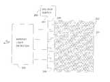
- FIG. 1schematically illustrates a voltage supply coupled to an array of light sensitive pixels as well as a pixel circuit that may be used in the present invention
- FIG. 2 aillustrates a block diagram of the present invention
- FIG. 2 billustrates a block diagram of the present invention having a single current monitor
- FIG. 2 cillustrates a block diagram of the present invention having multiple voltage supplies
- FIG. 2 dillustrates a block diagram of the present invention having isolated power rails
- FIG. 3 aillustrates a block diagram of the ambient light detector
- FIG. 3 billustrates a circuit that may be used as a current monitor in the ambient light detector
- FIGS. 4 a, 4 b, 4 c and 4 dillustrate various possible layouts for the imaging array for the detection of ambient light in specific areas of an array.
- FIG. 5illustrates a block diagram of an exposure control system with which the ambient light detector in accordance with the present invention may be used.
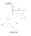
- FIG. 6illustrates the face of an image scanner.
- CMOS image sensorsare comprised of an array of light sensitive pixels integrated on a die.
- the signal generated by each pixelis proportional to the amount of charge collected by the pixel during an exposure or integration period.
- a leakage currentflows through the reset transistor and the photodiode in each pixel.
- the current flowing through the reverse biased photodiodeis proportional to the level of photons impinging on the photodiode at that time.
- the level of ambient light present when an image is being captured by the image arraycan greatly influence the quality of the captured image; this is particularly important when the captured image is being used for image recognition in instances such as bar-code reading.
- the level of light present when an image is being capturedmay also influence the amount of amplification that the image signals require as they are being processed for image recognition.
- an array 101 of light sensitive pixels 102which are normally laid out in rows and columns, are powered by a stable voltage supply 103 providing an output voltage V dd .
- One type of active pixel 102 that may be used in conjunction with the present inventionis illustrated, however, the invention may be carried out in conjunction with other types of active pixels.
- Some pixelsmay use photodiodes such as p ⁇ n photodiodes, p ⁇ i ⁇ n photodiodes and Schottky photodiodes.
- the active pixel 102 illustratedconsists of a reset transistor 108 , a source-follower transistor 109 , a p ⁇ n photodiode 107 , and a row-selection transistor 110 .
- a positive voltage signal V Ris applied to the gate of the reset transistor 108 through reset line 106 turning the transistor 108 ON in order to apply the voltage V dd across the photodiode 107 .
- the pixels 102are coupled to the voltage supply 103 through the array power rail 104 and a row power rails 105 .
- a currentwill flow through the pixel 102 as a pixel leakage current I PL .
- the pixel leakage Current I PL flowing through the reverse-biased p ⁇ n photodiode 107is proportional to the level of photons impinging on the photodiode 107 . In effect, the intensity of light hitting the photodiode 107 can be measured by monitoring the pixel leakage current I PL .
- the total current flowing through a row power rail 105 for all of the pixels 102 in that row during their resetis current I RP
- the total current flowing through the power rail 104 for all of the pixels 102 in the array 101 during their resetis current I AP .
- The, ambient light level impinging on the array 101may be determined by measuring the current flowing through a selected number of pixels 102 while they are being reset.
- FIG. 2 aAn embodiment of the present invention for monitoring the pixel leakage current is illustrated in FIG. 2 a wherein an ambient light detection circuit 220 is connected to the imaging array 201 in which the pixels 202 are laid out in rows and columns. It is preferred to have the ambient light detection circuit 220 integrated on the same die as the imaging array 201 , however this is not essential for the proper operation of the present invention.
- the voltage supply 203provides power to the imaging array 201 through the main power rail 204 which is coupled to the row power rails 205 . Further, a number of selected individual row power rails 205 are each coupled to the ambient light detection circuit 220 .
- the ambient light detection circuit 220detects the individual currents flowing through each of the selected row rails 205 , and outputs a signal P OUT representative the currents flowing.
- the output signal P OUTis a function of the currents I RP flowing to the pixels 202 in each of the selected row rails 205 and therefore can be used as a representation of the level of ambient light impinging on the pixels 202 in the array.
- the ambient light detection circuit 220 shown in FIG. 3 aillustrates one form that it may take to monitor currents flowing in one or more groups of pixels 202 in array 201 .
- a number of inputs 221 for individual connection to a selected number of row rails 205are each connected to a current monitor 211 through a small resistance 212 of value R RM . Care must be taken to assure that the inputs 221 are isolated from one another such that the monitors 211 will only monitor the current in the row rails 205 to which they are connected.
- the current monitor 211detects the current flowing through the small resistance 212 , and outputs an analog signal representative of that current flow to an analog to digital converter 213 .
- the analog to digital converter 213transforms the analog signal into a digital signal P consisting of a number of bits. Analog to digital converters are well known to those skilled in the art, and hence shall not be described further here.
- the outputs P from the various analog to digital converters 213are fed to a combiner 222 which may either combine all of the P signals into a single digital output signal P OUT or which may sequence the P signals into a string of digital outputs as signal P OUT representing the currents in the row rails 205 that had been selected.
- FIG. 3 billustrates one form that the current monitor 211 may take. It consists basically of a current-to-voltage converter 313 .
- the current I RM flowing through the small resistance 212is equal to the total amount of current I RT flowing through the row power rail 205 less the total leakage currents I RP flowing into the pixels 202 connected to that particular row rail 205 .
- the voltage at the inverting input 315 to the op-amp 314is approximately equivalent to the reference voltage V REF applied to the non-inverting input 316 to the op-amp 314 . This is possible by what is commonly known as a virtual ground between the inverting input 315 and non-inverting input 316 of the op-amp 314 . Due to the infinite impedance of the op-amp 314 all of the current I RM is forced to flow through the large resistance 317 of value R L . This leads to an output voltage level V OUT represented by the following equation:
- V OUTV REF ⁇ ( I RM *R L )
- V OUT on output terminal 318This establishes an output voltage level V OUT on output terminal 318 that is a function of the current I RM flowing through the small resistor 212 , which is a function of the total leakage current I RP flowing through the pixels 202 in that particular row 205 , which is a function of the amount of light impinging on the pixels 202 in that particular row 205 .
- the output voltage V OUTis directly proportional to the intensity of ambient light impinging on the pixels 202 in the selected row of the image sensor array 201 .
- V OUT on the output 318is then applied to the analog to digital converter 213 .
- a single current monitor 211may be coupled to the array rail 204 so as to measure the total leakage current for all pixels 202 in the array 201 as they are being simultaneously reset.
- the apparatus in this embodimentmay be operated such that the reset transistors 108 for the pixels 102 is controlled to reset sequentially one or more pixels in selected rows or columns or groups of pixels 202 as illustrated in FIG. 2 b.
- the resulting output signal V OUTwill consist of sequential digital outputs representing ambient light from the different parts of the array which can be combined to provide an output signal representative of the ambient light on the array.
- FIG. 2 cis an embodiment of the present invention where selected rows 205 of pixels 202 to be monitored by the ambient light detection circuit 220 are individually connected to separate voltage sources 203 .
- row rails 205 a, 205 b, 205 c and 205 dare connected to voltage supplies 203 a, 203 b, 203 c and 203 d respectively.
- the remaining row rails 205are connected to a further voltage supply 203 .
- the ambient light detection circuit 220includes a current monitor 211 a, 211 b, 211 c and 211 d and associated circuitry as described with respect to FIG. 3 a for monitoring the current individually on each of the row rails 205 a, 205 b, 205 c and 205 d respectively. In this way, all of the pixels 202 in the entire array 201 can be reset simultaneously and at the same time the currents in row rails 205 a, 205 b, 205 c and 205 d can be monitored.
- FIG. 2 dA further preferred embodiment is illustrated in FIG. 2 d where the row rails 205 a, 205 b, 205 c and 205 d are all connected to the same voltage supply 203 however through diodes 223 a, 223 b, 223 c and 223 d respectively.
- the diodes 223 a, 223 b, 223 c and 223 dallow the row rails 205 a, 205 b, 205 c and 205 d to be monitored individually while avoiding interference by currents in the remaining row rails 205 .
- all pixels 202 in an array 201are normally reset simultaneously, though this need not be the case to implement the present invention.
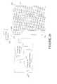
- FIGS. 4 a to 4 dwhich each show pixels 402 being laid out in an array 401 of 15 rows by 15 columns.
- FIG. 4 aillustrates one such configuration wherein the pixels 402 in column 7 are connected to a power rail 421 , the pixels 402 in column 8 are connected to a power rail 422 and the pixels 402 in column 9 are connected to a power rail 423 .
- the pixels 402 in row 7 that are in columns 1 to 6are connected to a rail 424
- the pixels 402 in row 8 that are in columns 1 to 6are connected to a rail 425
- the pixels 402 in row 9 that are in columns 1 to 6are connected to a rail 426
- the pixels 402 in row 7 that are in columns 10 to 15are connected to a rail 427
- the pixels 402 in row 8 that are in columns 10 to 15are connected to a rail 428
- the pixels 402 in row 9 that are in columns 10 to 15are connected to a rail 429 .
- rails 424 and 427may be connected together
- rails 425 and 428may be connected together
- rails 426 and 429may be connected together.
- Such a configurationwould allow a current monitor to be connected to each of the rails 421 to 426 in order to measure the leakage currents in the pixels 402 in rows 7 to 9 and columns 7 to 9 which results in a measurement of the ambient light falling in a cross pattern on the array 401 .
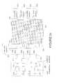
- the pixels 402are connected to these power rails in the following manner: the pixels 402 in column 1 that are in rows 1 to 6 are connected to a rail 431 and the pixels 402 that are in rows 10 to 15 are connected to rail 441 , the pixels 402 in column 2 that are in rows 1 to 6 are connected to a rail 432 and the pixels 402 that are in rows 10 to 15 are connected to rail 442 , the pixels 402 in column 3 that are in rows 1 to 6 are connected to a rail 433 and the pixels 402 that are in rows 10 to 15 are connected to rail 443 , the pixels 402 in column 4 that are in rows 1 to 6 are connected to a rail 434 and the pixels 402 that are in rows 10 to 15 are connected to rail 444 , and the pixels 402 in column 5 that are in rows 1 to 6 are connected to a rail 435 and the pixels 402 that are in rows 10 to 15 are connected to rail 445 .
- the pixels 402 in column 11 that are in rows 1 to 6are connected to a rail 436 and the pixels 402 that are in rows 10 to 15 are connected to rail 446
- the pixels 402 in column 12 that are in rows 1 to 6are connected to a rail 437 and the pixels 402 that are in rows 10 to 15 are connected to rail 447
- the pixels 402 in column 13 that are in rows 1 to 6are connected to a rail 438 and the pixels 402 that are in rows 10 to 15 are connected to rail 448
- the pixels 402 in column 14 that are in rows 1 to 6are connected to a rail 439 and the pixels 402 that are in rows 10 to 15 are connected to rail 449
- the pixels 402 in column 15 that are in rows 1 to 6are connected to a rail 440 and the pixels 402 that are in rows 10 to 15 are connected to rail 450 .
- FIG. 4 cillustrates an array 401 having a configuration wherein all of the pixels 402 in each column 1 to 15 are connected to a different power rail 430 . This configuration allows for the selection of particular columns, rather than rows as illustrated in FIG. 2 a, to measure the ambient light on the array 401 .
- FIG. 4 dillustrates yet another configuration wherein power rails 451 are connected to the row 1 to 8 pixels 420 in columns 6 to 10 and the power rails 453 are connected to the row 9 to 15 pixels 420 in columns 6 to 10 the power rails 451 and 453 extend across only half the imaging array 401 .
- Each of the power rails 452is connected to the column 1 to 5 pixels 420 for each of the rows 1 to 15, while each of the power rails 454 is connected to the column 11 to 15 pixels 420 for each of the rows 1 to 15 providing versatility in monitoring the leakage currents.
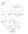
- FIG. 5illustrates the use of the present invention in an exposure controlled imager 500 as described in co-pending U.S. patent application Ser. No. 09/1689,368 filed on Oct. 12, 2000 which is incorporated herein by reference.
- the imaging circuit 501which is located on a wafer or die and which is represented by broken lines, normally includes an imaging array 502 , wordline drivers 503 and wordlines 504 , bitline readers 505 and bitlines 506 , an integration timer 507 , and a signal amplifier 509 .
- the bitline readers 505are connected to the signal amplifier 508 which amplifies the bitline reader 505 signals to produce the image output data.
- light detector circuits 520are also located on the die 501 adjacent to the imaging array 502 .
- the imaging circuitry 501 on the diemay further include an averaging circuit 510 , a look-up table and signal driver 511 and an illumination source control 512 .
- the signal driver 511includes output lines 513 to 515 respectively for signals to control the signal amplifier 508 , the integration timer 507 and the illumination control 512 .
- the illumination control 512is adapted to control an illumination source 513 may not necessarily be located on the imaging circuitry die 501 .
- the look-up table and signal driver 511determines the proper values for the illumination source control signal, the integration time control signal, and the gain control signal, these signals are fed to illumination source controller 512 , the integration timer 507 and the signal amplifier 508 respectively to adjust the brightness of the light source 513 , the exposure time of the imaging array 502 and the gain of the amplifier 508 , respectively.
- the look-up table and signal driver 511may consist of a microcontroller device such as the Strong-Arm SA-1110 and a read only memory programmed with data defining particular imaging needs in terms of light intensity, integration time, and signal gain in response to a measured level of ambient light.
- the sort of data contained thereinwould depend on the type of application the device was to be used for; for example a bar code reader would try to rely mostly on alterations of the integration time as this would be the power conscious method of ambient light adjustment.
- the light source 513may consist of any type of conventional light source that can be controlled in intensity. However, a particularly advantageous arrangement is illustrated in FIG. 6, which schematically illustrates the face of a scanner 600 .
- the imaging circuit 601is located at the center of the scanner face 602 .
- One or more LED light sources 603are positioned about the imaging circuit 601 to provide further lighting if required.
- the one or more LED's 603may each be controlled by a separate line in order to turn each LED 603 OFF or ON as desired. For example, if an object or target is close to the scanner face 602 , only one or two LED's might be turned ON; with the target a little further away, such as five or six inches, possibly three or four LED's 603 could be turned ON.
- the light source controller 512could control the driving current to each LED 603 , and increase or decrease the illumination from each LED 603 as required.
Landscapes
- Engineering & Computer Science (AREA)
- Multimedia (AREA)
- Signal Processing (AREA)
- Solid State Image Pick-Up Elements (AREA)
- Transforming Light Signals Into Electric Signals (AREA)
- Facsimile Heads (AREA)
- Facsimile Scanning Arrangements (AREA)
- Image Input (AREA)
Abstract
Description
Claims (54)
Priority Applications (4)
| Application Number | Priority Date | Filing Date | Title |
|---|---|---|---|
| US09/718,137US6469289B1 (en) | 2000-01-21 | 2000-11-21 | Ambient light detection technique for an imaging array |
| CA002330080ACA2330080A1 (en) | 2000-01-21 | 2001-01-03 | Ambient light detection technique for an imaging array |
| EP01300207AEP1162831A1 (en) | 2000-01-21 | 2001-01-10 | Ambient light detection technique for an imaging array |
| JP2001012631AJP4585694B2 (en) | 2000-01-21 | 2001-01-22 | Ambient light detection technology for imaging arrays |
Applications Claiming Priority (2)
| Application Number | Priority Date | Filing Date | Title |
|---|---|---|---|
| US17749600P | 2000-01-21 | 2000-01-21 | |
| US09/718,137US6469289B1 (en) | 2000-01-21 | 2000-11-21 | Ambient light detection technique for an imaging array |
Publications (1)
| Publication Number | Publication Date |
|---|---|
| US6469289B1true US6469289B1 (en) | 2002-10-22 |
Family
ID=26873371
Family Applications (1)
| Application Number | Title | Priority Date | Filing Date |
|---|---|---|---|
| US09/718,137Expired - LifetimeUS6469289B1 (en) | 2000-01-21 | 2000-11-21 | Ambient light detection technique for an imaging array |
Country Status (4)
| Country | Link |
|---|---|
| US (1) | US6469289B1 (en) |
| EP (1) | EP1162831A1 (en) |
| JP (1) | JP4585694B2 (en) |
| CA (1) | CA2330080A1 (en) |
Cited By (37)
| Publication number | Priority date | Publication date | Assignee | Title |
|---|---|---|---|---|
| US7086595B2 (en) | 2003-11-13 | 2006-08-08 | Metrologic Instruments, Inc. | Method of and apparatus for processing captured digital images of objects within a semi-automatic hand-supportable imaging-based bar code symbol reader so as to read 1d and/or 2d bar code symbols graphically represented therein |
| US20060256197A1 (en)* | 2005-05-11 | 2006-11-16 | Fultz William W | Method of operation for a vision-based occupant sensing system |
| US20060261256A1 (en)* | 2005-05-18 | 2006-11-23 | Stmicroelectronics (Research And Development) Limited | Method for operating an electronic imaging system, and electronics imaging system |
| US20070051812A1 (en)* | 2005-08-24 | 2007-03-08 | Intermec Ip Corp. | Method and apparatus employing imaging and/or scanning for reading machine-readable symbols such as barcode symbols |
| US20070109433A1 (en)* | 2005-11-16 | 2007-05-17 | Matsushita Electric Industrial Co., Ltd. | Solid-state imaging device for high-speed photography |
| US20070154202A1 (en)* | 2006-01-04 | 2007-07-05 | Lee King F | Method and apparatus to facilitate correcting rolling shutter images |
| US20070199998A1 (en)* | 2003-11-13 | 2007-08-30 | Anatoly Kotlarsky | Method of dynamically controlling illumination and image capturing operations in a digital image capture and processing system |
| US20070210166A1 (en)* | 2000-11-24 | 2007-09-13 | Knowles C H | Omni-directional digital image capturing and processing system comprising coplanar illumination and imaging stations automatically detecting object motion and velocity and adjusting exposure and/or illumination control parameters therewithin |
| US7270272B2 (en) | 2003-11-13 | 2007-09-18 | Metrologic Instruments, Inc. | Digital image-based bar code symbol reading system employing a multi-mode image-processing symbol reading subsystem |
| US7347374B2 (en) | 2003-11-13 | 2008-03-25 | Metrologic Instruments, Inc. | Hand-supportable digital imaging-based bar code symbol reader employing an event-driven system control subsystem, automatic IR-based object detection, and trigger-switch activated image capture and processing subsystem |
| US20090084943A1 (en)* | 2007-09-27 | 2009-04-02 | Johannes Solhusvik | Method and apparatus for ambient light detection |
| US7513428B2 (en) | 2001-11-21 | 2009-04-07 | Metrologic Instruments, Inc. | Planar laser illumination and imaging device employing laser current modulation to generate spectral components and reduce temporal coherence of laser beam, so as to achieve a reduction in speckle-pattern noise during time-averaged detection of images of objects illuminated thereby during imaging operations |
| US7523863B2 (en) | 1999-06-07 | 2009-04-28 | Metrologic Instruments, Inc. | Hand-supportable LED-based planar illumination and imaging system |
| US7527202B2 (en) | 2000-06-07 | 2009-05-05 | Metrologic Instruments, Inc. | Hand-supportable planar linear illumination and imaging (PLIIM) based code symbol reading system |
| US7527200B2 (en) | 1998-03-24 | 2009-05-05 | Metrologic Instruments, Inc. | Planar laser illumination and imaging (PLIIM) systems with integrated despeckling mechanisms provided therein |
| US7546952B2 (en) | 2000-11-24 | 2009-06-16 | Metrologic Instruments, Inc. | Method of illuminating objects during digital image capture operations by mixing visible and invisible spectral illumination energy at point of sale (POS) environments |
| US7594609B2 (en) | 2003-11-13 | 2009-09-29 | Metrologic Instruments, Inc. | Automatic digital video image capture and processing system supporting image-processing based code symbol reading during a pass-through mode of system operation at a retail point of sale (POS) station |
| US7607581B2 (en) | 2003-11-13 | 2009-10-27 | Metrologic Instruments, Inc. | Digital imaging-based code symbol reading system permitting modification of system features and functionalities |
| US7708205B2 (en) | 2003-11-13 | 2010-05-04 | Metrologic Instruments, Inc. | Digital image capture and processing system employing multi-layer software-based system architecture permitting modification and/or extension of system features and functions by way of third party code plug-ins |
| US7841533B2 (en) | 2003-11-13 | 2010-11-30 | Metrologic Instruments, Inc. | Method of capturing and processing digital images of an object within the field of view (FOV) of a hand-supportable digitial image capture and processing system |
| US20110205384A1 (en)* | 2010-02-24 | 2011-08-25 | Panavision Imaging, Llc | Variable active image area image sensor |
| US20130003079A1 (en)* | 2011-06-29 | 2013-01-03 | Holcombe Wayne T | Proximity sensor calibration |
| WO2013014501A1 (en)* | 2011-07-25 | 2013-01-31 | Aptina Imaging Corporation | Imaging systems with verification circuitry for monitoring standby leakage current levels |
| US20130187027A1 (en)* | 2012-01-20 | 2013-07-25 | Omnivision Technologies, Inc. | Image sensor with integrated ambient light detection |
| US20130243304A1 (en)* | 2012-03-14 | 2013-09-19 | Guang hai Jin | Array testing method and device |
| US20130278576A1 (en)* | 2012-04-18 | 2013-10-24 | Apple Inc. | Calibrated image-sensor-based ambient light sensor |
| US20140166859A1 (en)* | 2012-12-18 | 2014-06-19 | Stmicroelectronics (Grenoble 2) Sas | Circuit and method for measuring an ambient light level |
| WO2015002613A1 (en)* | 2013-07-03 | 2015-01-08 | Nanyang Technological University | Image sensor and method of controlling the same |
| US20150077609A1 (en)* | 2012-05-01 | 2015-03-19 | Sony Corporation | Image sensor and control method for image sensor |
| WO2015187197A1 (en)* | 2014-06-05 | 2015-12-10 | Secugen Corporation | Fingerprint sensing apparatus |
| US20170111600A1 (en)* | 2015-10-16 | 2017-04-20 | Capso Vision, Inc. | Single Image Sensor for Capturing Mixed Structured-light Images and Regular Images |
| US10402992B2 (en) | 2015-10-16 | 2019-09-03 | Capsovision Inc. | Method and apparatus for endoscope with distance measuring for object scaling |
| US10785428B2 (en) | 2015-10-16 | 2020-09-22 | Capsovision Inc. | Single image sensor for capturing mixed structured-light images and regular images |
| US10949634B2 (en) | 2005-06-03 | 2021-03-16 | Hand Held Products, Inc. | Apparatus having hybrid monochrome and color image sensor array |
| CN113419388A (en)* | 2021-08-23 | 2021-09-21 | 山东蓝贝思特教装集团股份有限公司 | Liquid crystal writing device and method adaptive to ambient light |
| US11317050B2 (en) | 2005-03-11 | 2022-04-26 | Hand Held Products, Inc. | Image reader comprising CMOS based image sensor array |
| CN115031835A (en)* | 2022-05-30 | 2022-09-09 | 歌尔股份有限公司 | A device's ambient light intensity detection method and related components |
Families Citing this family (5)
| Publication number | Priority date | Publication date | Assignee | Title |
|---|---|---|---|---|
| ATE338444T1 (en)* | 2002-04-08 | 2006-09-15 | Theben Ag | PROGRAMMABLE TWILIGHT SWITCH |
| US7486313B2 (en) | 2003-01-17 | 2009-02-03 | Biomorphic Vlsi, Inc. | System and method for automatic exposure control and white balancing for CMOS sensors |
| JP4696877B2 (en)* | 2005-11-29 | 2011-06-08 | ヤマハ株式会社 | Solid-state imaging device |
| JP4847202B2 (en) | 2006-04-27 | 2011-12-28 | キヤノン株式会社 | Imaging apparatus and radiation imaging system |
| CN112612329A (en)* | 2020-11-27 | 2021-04-06 | 苏州浪潮智能科技有限公司 | Server cabinet, image acquisition method and storage medium |
Citations (22)
| Publication number | Priority date | Publication date | Assignee | Title |
|---|---|---|---|---|
| US3991299A (en) | 1972-02-03 | 1976-11-09 | Norand Corporation | Bar code scanner |
| US4338514A (en) | 1980-04-07 | 1982-07-06 | Spin Physics, Inc. | Apparatus for controlling exposure of a solid state image sensor array |
| JPS57212878A (en) | 1981-06-25 | 1982-12-27 | Nippon Telegr & Teleph Corp <Ntt> | Solid-state image pickup device |
| USRE31370E (en) | 1974-04-01 | 1983-09-06 | Canon Kabushiki Kaisha | System for exposure measurement and/or focus detection by means of image sensor |
| US4471228A (en) | 1980-12-05 | 1984-09-11 | Fuji Photo Film Co., Ltd. | Solid-state image sensor with exposure controller |
| US4538060A (en) | 1982-05-31 | 1985-08-27 | Nippondenso Co., Ltd. | Optical reading apparatus having a reading sensor of electronic scanning type |
| EP0221545A2 (en) | 1985-11-06 | 1987-05-13 | Nippondenso Co., Ltd. | Optical information reading apparatus |
| US4677287A (en) | 1982-07-14 | 1987-06-30 | Canon Kabushiki Kaisha | Document reader with light source control |
| US4805010A (en) | 1987-05-29 | 1989-02-14 | Eastman Kodak Company | Still video camera with common circuit for color balance and exposure control |
| US4945418A (en) | 1988-02-01 | 1990-07-31 | Fuji Photo Film Co., Ltd. | Solid state image pickup apparatus with charge storage device |
| US4970379A (en) | 1987-04-30 | 1990-11-13 | Norand Corporation | Bar code scanner system and scanner circuitry therefor |
| US5335075A (en) | 1990-10-08 | 1994-08-02 | Olympus Optical Co., Ltd. | Image sensing apparatus having exposure level and dynamic range control circuit |
| EP0660598A1 (en) | 1993-12-27 | 1995-06-28 | Kabushiki Kaisha Toshiba | Solid state imaging device including monitoring pixel |
| WO1996003708A1 (en) | 1994-07-26 | 1996-02-08 | Metanetics Corporation | Automatic exposure single frame imaging systems |
| US5491330A (en) | 1993-08-10 | 1996-02-13 | Fujitsu Limited | Ambient light detector, laser lighting control device using the same suitable for bar code reader, and bar code reader |
| US5742340A (en) | 1995-06-06 | 1998-04-21 | Hughes Missile Systems Company | Ambient light automatic gain control for electronic imaging cameras and the like |
| US5808286A (en) | 1995-06-05 | 1998-09-15 | Asahi Kogaku Kogyo Kabushiki Kaisha | Data symbol reader utilizing ambient light illumination |
| US5910653A (en) | 1997-04-09 | 1999-06-08 | Telxon Corporation | Shelf tag with ambient light detector |
| US5932861A (en) | 1994-11-01 | 1999-08-03 | Fujitsu Limited | Ambient light detector, light source lighting controlling device, and reader |
| WO1999057605A1 (en) | 1998-05-05 | 1999-11-11 | Intel Corporation | Method and apparatus for processing a photocurrent in both discrete and continuous time |
| US5986705A (en) | 1997-02-18 | 1999-11-16 | Matsushita Electric Industrial Co., Ltd. | Exposure control system controlling a solid state image sensing device |
| US6315379B1 (en)* | 1999-10-26 | 2001-11-13 | Xerox Corporation | Systems and methods for selectively blocking image data |
- 2000
- 2000-11-21USUS09/718,137patent/US6469289B1/ennot_activeExpired - Lifetime
- 2001
- 2001-01-03CACA002330080Apatent/CA2330080A1/ennot_activeAbandoned
- 2001-01-10EPEP01300207Apatent/EP1162831A1/ennot_activeWithdrawn
- 2001-01-22JPJP2001012631Apatent/JP4585694B2/ennot_activeExpired - Fee Related
Patent Citations (22)
| Publication number | Priority date | Publication date | Assignee | Title |
|---|---|---|---|---|
| US3991299A (en) | 1972-02-03 | 1976-11-09 | Norand Corporation | Bar code scanner |
| USRE31370E (en) | 1974-04-01 | 1983-09-06 | Canon Kabushiki Kaisha | System for exposure measurement and/or focus detection by means of image sensor |
| US4338514A (en) | 1980-04-07 | 1982-07-06 | Spin Physics, Inc. | Apparatus for controlling exposure of a solid state image sensor array |
| US4471228A (en) | 1980-12-05 | 1984-09-11 | Fuji Photo Film Co., Ltd. | Solid-state image sensor with exposure controller |
| JPS57212878A (en) | 1981-06-25 | 1982-12-27 | Nippon Telegr & Teleph Corp <Ntt> | Solid-state image pickup device |
| US4538060A (en) | 1982-05-31 | 1985-08-27 | Nippondenso Co., Ltd. | Optical reading apparatus having a reading sensor of electronic scanning type |
| US4677287A (en) | 1982-07-14 | 1987-06-30 | Canon Kabushiki Kaisha | Document reader with light source control |
| EP0221545A2 (en) | 1985-11-06 | 1987-05-13 | Nippondenso Co., Ltd. | Optical information reading apparatus |
| US4970379A (en) | 1987-04-30 | 1990-11-13 | Norand Corporation | Bar code scanner system and scanner circuitry therefor |
| US4805010A (en) | 1987-05-29 | 1989-02-14 | Eastman Kodak Company | Still video camera with common circuit for color balance and exposure control |
| US4945418A (en) | 1988-02-01 | 1990-07-31 | Fuji Photo Film Co., Ltd. | Solid state image pickup apparatus with charge storage device |
| US5335075A (en) | 1990-10-08 | 1994-08-02 | Olympus Optical Co., Ltd. | Image sensing apparatus having exposure level and dynamic range control circuit |
| US5491330A (en) | 1993-08-10 | 1996-02-13 | Fujitsu Limited | Ambient light detector, laser lighting control device using the same suitable for bar code reader, and bar code reader |
| EP0660598A1 (en) | 1993-12-27 | 1995-06-28 | Kabushiki Kaisha Toshiba | Solid state imaging device including monitoring pixel |
| WO1996003708A1 (en) | 1994-07-26 | 1996-02-08 | Metanetics Corporation | Automatic exposure single frame imaging systems |
| US5932861A (en) | 1994-11-01 | 1999-08-03 | Fujitsu Limited | Ambient light detector, light source lighting controlling device, and reader |
| US5808286A (en) | 1995-06-05 | 1998-09-15 | Asahi Kogaku Kogyo Kabushiki Kaisha | Data symbol reader utilizing ambient light illumination |
| US5742340A (en) | 1995-06-06 | 1998-04-21 | Hughes Missile Systems Company | Ambient light automatic gain control for electronic imaging cameras and the like |
| US5986705A (en) | 1997-02-18 | 1999-11-16 | Matsushita Electric Industrial Co., Ltd. | Exposure control system controlling a solid state image sensing device |
| US5910653A (en) | 1997-04-09 | 1999-06-08 | Telxon Corporation | Shelf tag with ambient light detector |
| WO1999057605A1 (en) | 1998-05-05 | 1999-11-11 | Intel Corporation | Method and apparatus for processing a photocurrent in both discrete and continuous time |
| US6315379B1 (en)* | 1999-10-26 | 2001-11-13 | Xerox Corporation | Systems and methods for selectively blocking image data |
Non-Patent Citations (1)
| Title |
|---|
| Patent Abstracts of Japan, vol. 007, No. 072 (E-166), Mar. 25, 1983 & JP 57 212878 A (Nippon Denshin Denwa Kosha), Dec. 27, 1982 abstract. |
Cited By (208)
| Publication number | Priority date | Publication date | Assignee | Title |
|---|---|---|---|---|
| US7527200B2 (en) | 1998-03-24 | 2009-05-05 | Metrologic Instruments, Inc. | Planar laser illumination and imaging (PLIIM) systems with integrated despeckling mechanisms provided therein |
| US7644866B2 (en) | 1999-06-07 | 2010-01-12 | Metrologic Instruments, Inc. | Hand-supportable code symbol reader employing coplanar laser illumination and linear imaging |
| US7621455B2 (en) | 1999-06-07 | 2009-11-24 | Metrologic Instruments, Inc. | Hand-supportable code symbol reader employing coplanar laser illumination and linear imaging |
| US7533821B2 (en) | 1999-06-07 | 2009-05-19 | Metrologic Instruments, Inc. | Hand-supportable planar laser illumination and imaging (PLIIM) device for producing a planar laser illumination beam (PLIB) coplanar with the field of view (FOV) of a linear image detection array |
| US7523863B2 (en) | 1999-06-07 | 2009-04-28 | Metrologic Instruments, Inc. | Hand-supportable LED-based planar illumination and imaging system |
| US7527202B2 (en) | 2000-06-07 | 2009-05-05 | Metrologic Instruments, Inc. | Hand-supportable planar linear illumination and imaging (PLIIM) based code symbol reading system |
| US7611062B2 (en) | 2000-11-24 | 2009-11-03 | Metrologic Instruments, Inc. | Omni-directional digital image capturing and processing system employing coplanar illumination and imaging planes and area-type illumination and imaging zones with the horizontal and vertical sections of the system housing |
| US7537165B2 (en) | 2000-11-24 | 2009-05-26 | Metrologic Instruments, Inc. | Omni-directional digital image capturing and processing system employing coplanar illumination and imaging planes and area-type illumination and imaging zones within the system housing |
| US7905413B2 (en) | 2000-11-24 | 2011-03-15 | Metrologic Instruments, Inc. | Digital image capturing and processing system employing a plurality of coplanar illumination and imaging subsystems for digitally imaging objects in a 3D imaging volume, and a globally-deployed object motion detection subsystem for automatically detecting and analyzing the motion of objects passing through said 3-D imaging volume |
| US7878407B2 (en) | 2000-11-24 | 2011-02-01 | Metrologic Instruments, Inc. | POS-based digital image capturing and processing system employing automatic object motion detection and spectral-mixing based illumination techniques |
| US7819326B2 (en) | 2000-11-24 | 2010-10-26 | Metrologic Instruments, Inc. | Network of digital image capturing systems installed at retail POS-based stations and serviced by a remote image processing server in communication therewith |
| US7815113B2 (en) | 2000-11-24 | 2010-10-19 | Metrologic Instruments, Inc. | Method of and system for returning a consumer product in a retail environment so as to prevent or reduce employee theft, as well as provide greater accountability for returned merchandise in retail store environments |
| US7806335B2 (en) | 2000-11-24 | 2010-10-05 | Metrologic Instruments, Inc. | Digital image capturing and processing system for automatically recognizing objects in a POS environment |
| US7806336B2 (en) | 2000-11-24 | 2010-10-05 | Metrologic Instruments, Inc. | Laser beam generation system employing a laser diode and high-frequency modulation circuitry mounted on a flexible circuit |
| US7793841B2 (en) | 2000-11-24 | 2010-09-14 | Metrologic Instruments, Inc. | Laser illumination beam generation system employing despeckling of the laser beam using high-frequency modulation of the laser diode current and optical multiplexing of the component laser beams |
| US7784695B2 (en) | 2000-11-24 | 2010-08-31 | Metrologic Instruments, Inc. | Planar laser illumination module (PLIM) employing high-frequency modulation (HFM) of the laser drive currents and optical multplexing of the output laser beams |
| US7775436B2 (en) | 2000-11-24 | 2010-08-17 | Metrologic Instruments, Inc. | Method of driving a plurality of visible and invisible LEDs so as to produce an illumination beam having a dynamically managed ratio of visible to invisible (IR) spectral energy/power during object illumination and imaging operations |
| US7770796B2 (en) | 2000-11-24 | 2010-08-10 | Metrologic Instruments, Inc. | Device for producing a laser beam of reduced coherency using high-frequency modulation of the laser diode current and optical multiplexing of the output laser beam |
| US7762465B2 (en) | 2000-11-24 | 2010-07-27 | Metrologic Instruments, Inc. | Device for optically multiplexing a laser beam |
| US7731091B2 (en) | 2000-11-24 | 2010-06-08 | Metrologic Instruments, Inc. | Digital image capturing and processing system employing automatic object detection and spectral-mixing based illumination techniques |
| US7673802B2 (en) | 2000-11-24 | 2010-03-09 | Metrologic Instruments, Inc. | Automatic POS-based digital image capturing and processing system employing a plurality of area-type illumination and imaging zones intersecting within the 3D imaging volume of the system |
| US7665665B2 (en) | 2000-11-24 | 2010-02-23 | Metrologic Instruments, Inc. | Digital illumination and imaging subsystem employing despeckling mechanism employing high-frequency modulation of laser diode drive current and optical beam multiplexing techniques |
| US7661595B2 (en) | 2000-11-24 | 2010-02-16 | Metrologic Instruments, Inc. | Digital image capturing and processing system employing a plurality of area-type illuminating and imaging stations projecting a plurality of coextensive area-type illumination and imaging zones into a 3D imaging volume, and controlling operations therewithin using |
| US7661597B2 (en) | 2000-11-24 | 2010-02-16 | Metrologic Instruments, Inc. | Coplanar laser illumination and imaging subsystem employing spectral-mixing and despeckling of laser illumination |
| US7658330B2 (en) | 2000-11-24 | 2010-02-09 | Metrologic Instruments, Inc. | Automatic POS-based digital image capturing and processing system employing object motion controlled area-type illumination and imaging operations |
| US20070210166A1 (en)* | 2000-11-24 | 2007-09-13 | Knowles C H | Omni-directional digital image capturing and processing system comprising coplanar illumination and imaging stations automatically detecting object motion and velocity and adjusting exposure and/or illumination control parameters therewithin |
| US7651028B2 (en) | 2000-11-24 | 2010-01-26 | Metrologic Instruments, Inc. | Intelligent system for automatically recognizing objects at a point of sale (POS) station by omni-directional imaging of the objects using a complex of coplanar illumination and imaging subsystems |
| US7614560B2 (en) | 2000-11-24 | 2009-11-10 | Metrologic Instruments, Inc. | Method of illuminating objects at a point of sale (POS) station by adaptively controlling the spectral composition of the wide-area illumination beam produced from an illumination subsystem within an automatic digital image capture and processing system |
| US8172141B2 (en) | 2000-11-24 | 2012-05-08 | Metrologic Instruments, Inc. | Laser beam despeckling devices |
| US7594608B2 (en) | 2000-11-24 | 2009-09-29 | Metrologic Instruments, Inc. | Automatic omnidirectional bar code symbol reading system employing linear-type and area-type bar code symbol reading stations within the system housing |
| US8042740B2 (en) | 2000-11-24 | 2011-10-25 | Metrologic Instruments, Inc. | Method of reading bar code symbols on objects at a point-of-sale station by passing said objects through a complex of stationary coplanar illumination and imaging planes projected into a 3D imaging volume |
| US20070262153A1 (en)* | 2000-11-24 | 2007-11-15 | Knowles C H | Digital image capturing and processing system for producing and projecting a complex of coplanar illumination and imaging planes into a 3D imaging volume and controlling illumination control parameters in said system using the detected motion and velocity of objects present therewithin |
| US7571859B2 (en) | 2000-11-24 | 2009-08-11 | Metrologic Instruments, Inc. | Digital-imaging based code symbol reading system employing a plurality of coplanar illumination and imaging subsystems, global object motion detection subsystem for automatically detecting objects within its 3D imaging volume, and global control subsystem for managing the state of operation of said coplanar illumination and imaging substems |
| US7584892B2 (en) | 2000-11-24 | 2009-09-08 | Metrologic Instruments, Inc. | Digital-imaging based code symbol reading system employing a plurality of coplanar illumination and imaging subsystems, each having a local object motion detection subsystem for automatic detecting objects within the 3D imaging volume, and a local control subsystem for transmitting object detection state data to a global control subsystem for managing the state of operation of said coplanar illumination and imaging subsystems |
| US20070278308A1 (en)* | 2000-11-24 | 2007-12-06 | Metrologic Instruments, Inc. | Digital image capturing and processing system employing a plurality of coplanar illumination and imaging subsystems for digitally imaging objects in a 3D imaging volume, and a globally-deployed object motion detection subsystem for automatically detecting and analyzing the motion of object passing through said 3D imaging volume |
| US7581680B2 (en) | 2000-11-24 | 2009-09-01 | Metrologic Instruments, Inc. | Omni-directional digital image capturing and processing system employing coplanar illumination and imaging stations in horizontal and vertical housing sections of the system |
| US7578442B2 (en) | 2000-11-24 | 2009-08-25 | Metrologic Instruments, Inc. | Method of and apparatus for identifying consumer products in a retail environment when bar code symbols on the products are not readable or have been removed from packaging |
| US20080029600A1 (en)* | 2000-11-24 | 2008-02-07 | Metrologic Instruments, Inc. | Digital-imaging based code symbol reading system employing a plurality of coplanar illumination and imaging subsystems, each having a local object motion detection subsystem for automatic detecting objects within the 3D imaging volume, and a local control subsystem for transmitting object detection state data to a global control subsystem for managing the state of operation of said coplanar illumination and imaging subsystems |
| US7578445B2 (en) | 2000-11-24 | 2009-08-25 | Metrologic Instruments, Inc. | Automatic POS-based digital image capturing and processing system employing object motion controlled area-type illumination and imaging operations |
| US7575169B2 (en) | 2000-11-24 | 2009-08-18 | Metrologic Instruments, Inc. | Digital image capturing and processing system for producing and projecting a plurality of coextensive area-type illumination and imaging zones into a 3D imaging volume and controlling illumination control parameters in said system using the detected motion of objects present therewithin |
| US7575170B2 (en) | 2000-11-24 | 2009-08-18 | Metrologic Instruments, Inc. | POS-based digital image capturing and processing system using automatic object detection, spectral-mixing based illumination and linear imaging techniques |
| US7588188B2 (en) | 2000-11-24 | 2009-09-15 | Metrologic Instruments, Inc. | Pos-based digital image capturing and processing system using automatic object detection, spectral-mixing based illumination and linear imaging techniques |
| US7571858B2 (en) | 2000-11-24 | 2009-08-11 | Metrologic Instruemtns, Inc. | POS-based digital image capturing and processing system using automatic object detection, spectral-mixing based illumination and linear imaging techniques |
| US7568626B2 (en) | 2000-11-24 | 2009-08-04 | Metrologic Instruments, Inc. | Automatic POS-based digital image capturing and processing system employing a plurality of area-type illumination and imaging zones intersecting within the 3D imaging volume of the system |
| US7559474B2 (en) | 2000-11-24 | 2009-07-14 | Metrologic Instruments, Inc. | Automatic omnidirectional bar code symbol reading system employing linear-type and area-type bar code symbol reading stations within the system housing |
| US7556199B2 (en) | 2000-11-24 | 2009-07-07 | Metrologic Instruments, Inc. | Digital image capturing and processing system employing a plurality of coplanar illuminating and imaging stations projecting a complex of coplanar illumination and imaging planes into a 3D imaging volume so as to support pass-through and presentation modes of digital imaging at a point of sale (POS) environment |
| US7546952B2 (en) | 2000-11-24 | 2009-06-16 | Metrologic Instruments, Inc. | Method of illuminating objects during digital image capture operations by mixing visible and invisible spectral illumination energy at point of sale (POS) environments |
| US7543749B2 (en) | 2000-11-24 | 2009-06-09 | Metrologic Instruments, Inc. | Digital image capturing and processing system having a plurality of coplanar illumination and imaging subsystems, each employing a dual-type coplanar linear illumination and imaging engine that supports image-processing based object motion and velocity detection, and automatic image formation and detection along the coplanar illumination and imaging plane produced thereby |
| US7540422B2 (en) | 2000-11-24 | 2009-06-02 | Metrologic Instruments, Inc. | Digital image capturing and processing system employing imaging window protection plate having an aperture pattern and being disposed over said imaging window and beneath which resides a plurality of coplanar illumination and imaging stations |
| US7540424B2 (en) | 2000-11-24 | 2009-06-02 | Metrologic Instruments, Inc. | Compact bar code symbol reading system employing a complex of coplanar illumination and imaging stations for omni-directional imaging of objects within a 3D imaging volume |
| US20070262150A1 (en)* | 2000-11-24 | 2007-11-15 | Knowles C H | Digital image capturing and processing system employing a plurality of coplanar illuminating and imaging stations projecting a plurality of coplanar illumination and imaging planes into a 3D imaging volume, and controlling operations therewithin using control data derived from motion data collected from the automated detection of objects passing through said 3D imaging volume |
| US7533820B2 (en) | 2000-11-24 | 2009-05-19 | Metrologic Instruments, Inc. | Digital image capturing and processing system employing coplanar illumination and imaging stations which generate coplanar illumination and imaging planes only when and where an object is being moved within the 3D imaging volume |
| US7533823B2 (en) | 2000-11-24 | 2009-05-19 | Metrologic Instruments, Inc. | Digital image capturing and processing system employing a plurality of coplanar illuminating and imaging stations projecting a plurality of coplanar illumination and imaging planes into a 3D imaging volume, and controlling operations therewithin using control data derived from motion data collected from the automated detection of objects passing through said 3D imaging volume |
| US7530497B2 (en) | 2000-11-24 | 2009-05-12 | Metrologic Instruments, Inc. | Digital image capturing and processing system employing an image capturing and processing module and an integrated electronic weigh scale module having a load cell centrally located with respect to said image capturing and processing module |
| US7516898B2 (en) | 2000-11-24 | 2009-04-14 | Metrologic Instruments, Inc. | Digital image capturing and processing system for producing and projecting a complex of coplanar illumination and imaging planes into a 3D imaging volume and controlling illumination control parameters in said system using the detected motion and velocity of object |
| US7527204B2 (en) | 2000-11-24 | 2009-05-05 | Metrologic Instruments, Inc. | Omni-directional digital image capturing and processing system comprising coplanar illumination and imaging stations automatically detecting object motion and velocity and adjusting exposure and/or illumination control parameters therewithin |
| US7520433B2 (en) | 2000-11-24 | 2009-04-21 | Metrologic Instruments, Inc. | Method for intelligently controlling the illumination and imagine of objects as they are moved through the 3D imaging volume of a digital image capturing and processing system |
| US7513428B2 (en) | 2001-11-21 | 2009-04-07 | Metrologic Instruments, Inc. | Planar laser illumination and imaging device employing laser current modulation to generate spectral components and reduce temporal coherence of laser beam, so as to achieve a reduction in speckle-pattern noise during time-averaged detection of images of objects illuminated thereby during imaging operations |
| US7861936B2 (en) | 2003-11-13 | 2011-01-04 | Metrologic Instruments, Inc. | digital image capturing and processing system allowing third-parties to extend the features and functions of said system, and modify the standard behavior thereof without permanently modifying the standard features and functions thereof |
| US7178733B2 (en) | 2003-11-13 | 2007-02-20 | Metrologic Instruments, Inc. | Hand-supportable imaging-based bar code symbol reader employing automatic object presence and range detection to control the generation of near-field and far-field wide-area illumination during bar code symbol imaging operations |
| US7086595B2 (en) | 2003-11-13 | 2006-08-08 | Metrologic Instruments, Inc. | Method of and apparatus for processing captured digital images of objects within a semi-automatic hand-supportable imaging-based bar code symbol reader so as to read 1d and/or 2d bar code symbols graphically represented therein |
| US9785811B2 (en) | 2003-11-13 | 2017-10-10 | Metrologic Instruments, Inc. | Image capture and processing system supporting a multi-tier modular software architecture |
| US7510122B2 (en) | 2003-11-13 | 2009-03-31 | Metrologic Instruments, Inc. | Portable digital image capturing and processing system employing an area-type image sensing array exposed to illumination produced from an LED-based illumination array and measured using a photodector operated independently from said area-type image sensing array |
| US7503499B2 (en) | 2003-11-13 | 2009-03-17 | Metrologic Instruments, Inc. | Digital image capturing and processing system producing narrow-band illumination when image sensor elements in a state of integration, and simultaneously detecting narrow-band illumination using an area-type image sensor and independently-operated photo-detector |
| US7503498B2 (en) | 2003-11-13 | 2009-03-17 | Metrologic Instruments, Inc. | Hand-supportable digital image capturing and processing system employing an area-type image sensing array exposed to illumination from an LED-based illumination array only when all sensor elements in said image-sensing array are activated and in a state of integration |
| US7540425B2 (en) | 2003-11-13 | 2009-06-02 | Metrologic Instruments, Inc. | Method of dynamically controlling illumination and image capturing operations in a digital image capture and processing system |
| US7494063B2 (en) | 2003-11-13 | 2009-02-24 | Metrologic Instruments, Inc. | Automatic imaging-based code symbol reading system supporting a multi-tier modular software architecture, automatic illumination control, and video image capture and processing techniques |
| US7490774B2 (en) | 2003-11-13 | 2009-02-17 | Metrologic Instruments, Inc. | Hand-supportable imaging based bar code symbol reader employing automatic light exposure measurement and illumination control subsystem integrated therein |
| US7543752B2 (en) | 2003-11-13 | 2009-06-09 | Metrologic Instruments, Inc. | Digital image capture and processing system employing a multi-mode illumination subsystem adaptable to ambient illumination levels |
| US7490778B2 (en) | 2003-11-13 | 2009-02-17 | Metrologic Instruments, Inc. | Method of reading code symbols using a hand-supportable digital image capturing and processing device employing a micro-computing platform supporting an event-driven multi-tier modular software architecture |
| US7546951B2 (en) | 2003-11-13 | 2009-06-16 | Meterologic Instruments, Inc. | Digital image capture and processing system employing real-time analysis of image exposure quality and the reconfiguration of system control parameters based on the results of such exposure quality analysis |
| US7487917B2 (en) | 2003-11-13 | 2009-02-10 | Metrologic Instruments, Inc. | Automatic digital-imaging based code symbol reading system supporting pass-through and presentation modes of system operation using automatic object direction detection, narrow-area and wide-area illumination control, and narrow-area and wide-area video image capture and processing techniques |
| US7484666B2 (en) | 2003-11-13 | 2009-02-03 | Metrologic Instruments, Inc. | Automatic digital-imaging based bar code symbol reading system supporting pass-through and presentation modes of system operation using automatic object direction detection and illumination control, and video image capture and processing techniques |
| US7469835B2 (en) | 2003-11-13 | 2008-12-30 | Metrologic Instruments, Inc. | Digital-imaging based code symbol reading system employing an event-driven multi-tier modular software architecture and supporting automatic operating system login and loading of code symbol reading application |
| US7559475B2 (en) | 2003-11-13 | 2009-07-14 | Metrologic Instruments, Inc. | Automatic digital-imaging based bar code symbol reading system supporting a pass-through mode of system operation using automatic object direction detection and illumination control, and video image capture and processing techniques |
| US7568625B2 (en) | 2003-11-13 | 2009-08-04 | Metpologic Instruments, Inc. | Hand-supportable digital image-processing based bar code symbol reading system employing image cropping zone (ICZ) framing and post-image capture cropping |
| US7464877B2 (en) | 2003-11-13 | 2008-12-16 | Metrologic Instruments, Inc. | Digital imaging-based bar code symbol reading system employing image cropping pattern generator and automatic cropped image processor |
| US7428998B2 (en) | 2003-11-13 | 2008-09-30 | Metrologic Instruments, Inc. | Automatic hand-supportable image-based bar code symbol reader having image-processing based bar code reading subsystem employing simple decode image processing operations applied in an outwardly-directed manner referenced from the center of a captured narrow-area digital image of an object bearing a 1D bar code symbol |
| US7407109B2 (en) | 2003-11-13 | 2008-08-05 | Metrologic Instruments, Inc. | Digital-imaging based code symbol reading system employing a micro-computing platform supporting an event-driven multi-tier modular software architecture |
| US7900839B2 (en) | 2003-11-13 | 2011-03-08 | Metrologic Instruments, Inc. | Hand-supportable digital image capture and processing system having a printed circuit board with a light transmission aperture, through which the field of view (FOV) of the image detection array and visible targeting illumination beam are projected using a FOV-folding mirror |
| US7360706B2 (en) | 2003-11-13 | 2008-04-22 | Metrologic Instruments, Inc. | Hand-supportable imaging-based auto-discriminating 1D/2D bar code symbol reader employing a multi-mode image processing bar code symbol reading subsystem having a plurality of modes of operation which are dynamically reconfigurable in response to real-time image analysis |
| US7357325B2 (en) | 2003-11-13 | 2008-04-15 | Metrologic Instruments, Inc. | Hand-supportable imaging-based bar code symbol reader employing a CMOS-type image sensor using global exposure techniques |
| US7347374B2 (en) | 2003-11-13 | 2008-03-25 | Metrologic Instruments, Inc. | Hand-supportable digital imaging-based bar code symbol reader employing an event-driven system control subsystem, automatic IR-based object detection, and trigger-switch activated image capture and processing subsystem |
| US7325738B2 (en) | 2003-11-13 | 2008-02-05 | Metrologic Instruments, Inc. | Method of and system for determining the lower limit of decoding resolution in an imaging-based bar code symbol reader |
| US7320431B2 (en) | 2003-11-13 | 2008-01-22 | Metrologic Instruments, Inc. | Digital imaging-based bar code symbol reading system employing a multi-mode illumination subsystem with far-field and near field led-based illumination arrays |
| US9355288B2 (en) | 2003-11-13 | 2016-05-31 | Metrologic Instruments, Inc. | Image capture and processing system supporting a multi-tier modular software architecture |
| US7299986B2 (en) | 2003-11-13 | 2007-11-27 | Metrologic Instruments, Inc. | Digital imaging-based bar code symbol driven portable data terminal system |
| US7588190B2 (en) | 2003-11-13 | 2009-09-15 | Metrologic Instruments, Inc. | Digital-imaging code symbol reading system supporting automatic programming of system parameters for automatic configuration of said system in hands-on and hands-free modes of operation |
| US7594609B2 (en) | 2003-11-13 | 2009-09-29 | Metrologic Instruments, Inc. | Automatic digital video image capture and processing system supporting image-processing based code symbol reading during a pass-through mode of system operation at a retail point of sale (POS) station |
| US7293714B2 (en) | 2003-11-13 | 2007-11-13 | Metrologic Instruments, Inc. | Hand-supportable digital imaging-based bar code symbol reading system automatically processing captured images along parallel virtual scan lines based on the maximum pixel height of the region of interest (ROI) |
| US7604175B2 (en) | 2003-11-13 | 2009-10-20 | Metrologic Instruments, Inc. | Method of reading bar code symbols using a digital-imaging based code symbol reading system employing an event-driven multi-tier modular software architecture and supporting automatic operating system login and loading of bar code symbol reading application |
| US7607581B2 (en) | 2003-11-13 | 2009-10-27 | Metrologic Instruments, Inc. | Digital imaging-based code symbol reading system permitting modification of system features and functionalities |
| US7284705B2 (en) | 2003-11-13 | 2007-10-23 | Metrologic Instruments, Inc. | Hand-supportable semi-automatic digital imaging-based bar code symbol reading system realized upon a multi-tier modular software platform |
| US7611064B2 (en) | 2003-11-13 | 2009-11-03 | Metrologic Instruments, Inc. | Digital image capture and processing system having automatic illumination measurement and control capabilities realized using a photodetector operating independently of the image sensing array, and an image-processing based illumination metering program for automatically adjusting the illumination duration of the system during object illumination and imaging operations |
| US7281661B2 (en) | 2003-11-13 | 2007-10-16 | Metrologic Instruments, Inc. | Hand-supportable digital imaging-based bar code symbol reading system employing a method of intelligently illuminating an object so as to generate a digital image thereof which is substantially free of noise caused by specular-type reflection |
| US7278575B2 (en) | 2003-11-13 | 2007-10-09 | Metrologic Instruments, Inc. | Hand-supportable image-based bar code symbol reader employing helically-sweeping feature-extraction analysis on a captured digital image of an object referenced from the center thereof |
| US7624926B2 (en) | 2003-11-13 | 2009-12-01 | Metrologic Instruments, Inc. | Method of automatically reading code symbols on objects present within the field of view (FOV) of a hand-supportable digital-imaging based code symbol reader, by simultaneously projecting an image cropping zone (ICZ) framing pattern and a field of illumination within the FOV during object illumination and imaging operations |
| US7637433B1 (en) | 2003-11-13 | 2009-12-29 | Metrologic Instruments, Inc. | Digital image capture and processing system employing a micro-computing platform with an event-driven multi-tier modular software architecture and supporting an image-processing based illumination metering program for automatically adjusting illumination during object illumination and imaging operations |
| US7637432B2 (en) | 2003-11-13 | 2009-12-29 | Metrologic Instruments, Inc. | Automatic point-of-sale based code symbol reading system employing automatic object motion detection and illumination control, and digital video image capturing and processing techniques |
| US7273180B2 (en) | 2003-11-13 | 2007-09-25 | Metrologic Instruments, Inc. | Hand-supportable imaging-based bar code symbol reader having a multi-mode bar code symbol image processor dynamically reconfigurable in response to real-time image processing operations carried out on captured images |
| US7270272B2 (en) | 2003-11-13 | 2007-09-18 | Metrologic Instruments, Inc. | Digital image-based bar code symbol reading system employing a multi-mode image-processing symbol reading subsystem |
| US7654461B2 (en) | 2003-11-13 | 2010-02-02 | Metrologic Instruments, Inc, | Automatically-triggered digital video imaging based code symbol reading system employing illumination and imaging subsystems controlled in response to real-time image quality analysis |
| US7267282B2 (en) | 2003-11-13 | 2007-09-11 | Metrologic Instruments, Inc. | Hand-supportable imaging-based bar code symbol reader capable of exposing an automatically detected object to a field of narrow-band LED-based illumination only when substantially all rows of pixels in a CMOS image sensing array are in a state of integration |
| US20070199998A1 (en)* | 2003-11-13 | 2007-08-30 | Anatoly Kotlarsky | Method of dynamically controlling illumination and image capturing operations in a digital image capture and processing system |
| US7255279B2 (en) | 2003-11-13 | 2007-08-14 | Metrologic Instruments, Inc. | Hand-supportable digital imaging-based bar code reading system wherein, during each imaging cycle, a single frame of pixel data is automatically detected by a CMOS area-type image sensing array when substantially all rows of pixels therein are in a state of integration and have a common integration time, and then pixel data is transmitted from said CMOS area-type image sensing array into a FIFO buffer, and then mapped into memory for subsequent image processing |
| US7243847B2 (en) | 2003-11-13 | 2007-07-17 | Metrologic Instruments, Inc. | Digital imaging-based bar code symbol reader employing an LED-based illumination subsystem driven by an automatic light exposure measurement and illumination control subsystem |
| US7240844B2 (en) | 2003-11-13 | 2007-07-10 | Metrologic Instruments, Inc. | Hand-suportable imaging-based bar code symbol reader employing an automatic light exposure measurement and illumination control subsystem for measuring illumination exposure on CMOS image sensing array and controlling LED illumination array driver circuitry |
| US7681799B2 (en) | 2003-11-13 | 2010-03-23 | Metrologic Instruments, Inc. | Method of reading code symbols using a digital image capturing and processing system employing a micro-computing platform with an event-driven multi-tier software architecture |
| US9104930B2 (en) | 2003-11-13 | 2015-08-11 | Metrologic Instruments, Inc. | Code symbol reading system |
| US7708205B2 (en) | 2003-11-13 | 2010-05-04 | Metrologic Instruments, Inc. | Digital image capture and processing system employing multi-layer software-based system architecture permitting modification and/or extension of system features and functions by way of third party code plug-ins |
| US7712666B2 (en) | 2003-11-13 | 2010-05-11 | Metrologic Instruments, Inc. | Automatically-triggered digital video-imaging based code symbol reading system supporting dynamically controlled object illumination and digital video-imaging operations |
| US8844822B2 (en) | 2003-11-13 | 2014-09-30 | Metrologic Instruments, Inc. | Image capture and processing system supporting a multi-tier modular software architecture |
| US7735737B2 (en) | 2003-11-13 | 2010-06-15 | Metrologic Instruments, Inc. | Automatically-triggered digital video-imaging based code symbol reading system supporting ambient illumination mode automatically selected by adaptive control process |
| US7237722B2 (en) | 2003-11-13 | 2007-07-03 | Metrologic Instruments, Inc. | Hand-supported imaging-based bar code symbol reader employing a multi-mode image-processing based bar code reading subsystem with modular image-processing architecture |
| US7225988B2 (en) | 2003-11-13 | 2007-06-05 | Metrologic Instruments, Inc. | Hand-supportable imaging-based bar code symbol reader employing a tri-mode led-based illumination subsystem |
| US7770798B2 (en) | 2003-11-13 | 2010-08-10 | Metrologic Instruments, Inc. | Automatically-triggered digital video-imaging based code symbol reading system for use in a point-of-sale (POS) environment |
| US7225989B2 (en) | 2003-11-13 | 2007-06-05 | Metrologic Instruments, Inc. | Method of performing auto-discrimination of 1D/2D bar code symbologies in a semi-automatic hand-supportable imaging-based bar code symbol reader having narrow-area and wide-area image capture modes of operation |
| US8479992B2 (en) | 2003-11-13 | 2013-07-09 | Metrologic Instruments, Inc. | Optical code symbol reading system employing an acoustic-waveguide structure for coupling sonic energy, produced from an electro-transducer, to sound wave ports formed in the system housing |
| US7789309B2 (en) | 2003-11-13 | 2010-09-07 | Metrologic Instruments, Inc. | Automatic digital video-imaging based code symbol reading system employing illumination and imaging subsystems controlled within a control loop maintained as long as a code symbol has not been successfully read and the object is detected in the field of view of the system |
| US8366005B2 (en) | 2003-11-13 | 2013-02-05 | Metrologic Instruments, Inc. | Hand-supportable digital image capture and processing system supporting a multi-tier modular software architecture |
| US7216810B2 (en) | 2003-11-13 | 2007-05-15 | Metrologic Instruments, Inc. | Hand-supportable multi-mode digital imaging-based bar code symbol reader employing an automatic illumination and exposure control subsystem that automatically controls the operation of a multi-mode led-based illumination subsystem so that detected objects are sufficiently illuminated and good quality digital images thereof are formed and detected |
| US7213762B2 (en) | 2003-11-13 | 2007-05-08 | Metrologic Instruments, Inc. | Hand-supportable imaging-based bar code symbol reader employing a CMOS-type image sensing array in combination with a band-pass optical filter subsystem, narrow-band illumination subsystem, and automatic light exposure measurement and illumination control subsystem |
| US7527206B2 (en) | 2003-11-13 | 2009-05-05 | Metrologic Instruments, Inc. | Method of setting the time duration of illumination from an LED-based illumination array employed in a digital imaging-based code symbol reader, using an image-processing based illumination metering program executed therewithin |
| US8317105B2 (en) | 2003-11-13 | 2012-11-27 | Metrologic Instruments, Inc. | Optical scanning system having an extended programming mode and method of unlocking restricted extended classes of features and functionalities embodied therewithin |
| US7128266B2 (en) | 2003-11-13 | 2006-10-31 | Metrologic Instruments. Inc. | Hand-supportable digital imaging-based bar code symbol reader supporting narrow-area and wide-area modes of illumination and image capture |
| US7815121B2 (en) | 2003-11-13 | 2010-10-19 | Metrologic Instruments, Inc. | Method of modifying and/or extending the standard features and functions of a digital image capture and processing system |
| US7185817B2 (en) | 2003-11-13 | 2007-03-06 | Metrologic Instruments, Inc. | Hand-supportable digital imaging-based bar codes symbol reader employing multi-mode subsystems |
| US7841533B2 (en) | 2003-11-13 | 2010-11-30 | Metrologic Instruments, Inc. | Method of capturing and processing digital images of an object within the field of view (FOV) of a hand-supportable digitial image capture and processing system |
| US7845559B2 (en) | 2003-11-13 | 2010-12-07 | Metrologic Instruments, Inc. | Hand-supportable digital image capture and processing system employing visible targeting illumination beam projected from an array of visible light sources on the rear surface of a printed circuit (PC) board having a light transmission aperture, and reflected off multiple folding mirrors and projected through the light transmission aperture into a central portion of the field of view of said system |
| US7845561B2 (en) | 2003-11-13 | 2010-12-07 | Metrologic Instruments, Inc. | Digital image capture and processing system supporting a periodic snapshot mode of operation wherein during each image acquisition cycle, the rows of image detection elements in the image detection array are exposed simultaneously to illumination |
| US7845563B2 (en) | 2003-11-13 | 2010-12-07 | Metrologic Instruments, Inc. | Digital image capture and processing system employing an illumination subassembly mounted about a light transmission aperture, and a field of view folding mirror disposed beneath the light transmission aperture |
| US7854384B2 (en) | 2003-11-13 | 2010-12-21 | Metrologic Instruments, Inc. | Digital image capture and processing engine employing optical waveguide technology for collecting and guiding LED-based illumination during object illumination and image capture modes of operation |
| US7188770B2 (en) | 2003-11-13 | 2007-03-13 | Metrologic Instruments, Inc. | Hand-supportable semi-automatic imaging-based bar code reading system wherein an led-based illumination subsystem automatically illuminates a detected target object in a narrow-area field of illumination, and illuminates the detected target object in a wide-area field of illumination upon manual activation of a trigger switch |
| US7513430B2 (en) | 2003-11-13 | 2009-04-07 | Metrologic Instruments, Inc. | Digital image capturing and processing system employing an area-type image sensing array exposed to narrow-band illumination from a narrow-band illumination subsystem for a time duration controlled using a photodetector operated independently from said area-type image sensing array |
| US7575167B2 (en) | 2003-11-13 | 2009-08-18 | Metrologic Instruments, Inc. | Method of dynamically managing system control parameters in a digital image capture and processing system |
| US8157175B2 (en) | 2003-11-13 | 2012-04-17 | Metrologic Instruments, Inc. | Digital image capture and processing system supporting a presentation mode of system operation which employs a combination of video and snapshot modes of image detection array operation during a single cycle of system operation |
| US7922089B2 (en) | 2003-11-13 | 2011-04-12 | Metrologic Instruments, Inc. | Hand-supportable digital image capture and processing system employing automatic object presence detection to control automatic generation of a linear targeting illumination beam within the field of view (FOV), and manual trigger switching to initiate illumination |
| US7950583B2 (en) | 2003-11-13 | 2011-05-31 | Metrologic Instruments, Inc | Automatic digital video imaging based code symbol reading system employing an automatic object motion controlled illumination subsystem |
| US7967209B2 (en) | 2003-11-13 | 2011-06-28 | Metrologic Instruments, Inc. | Method of blocking a portion of illumination rays generated by a countertop-supported digital imaging system, and preventing illumination rays from striking the eyes of the system operator or nearby consumers during operation of said countertop-supported digital image capture and processing system installed at a retail point of sale (POS) station |
| US7980471B2 (en) | 2003-11-13 | 2011-07-19 | Metrologic Instruments, Inc. | Method of unlocking restricted extended classes of features and functionalities embodied within a digital image capture and processing system by reading feature/functionality-unlocking type code symbols |
| US7988053B2 (en) | 2003-11-13 | 2011-08-02 | Metrologic Instruments, Inc. | Digital image capture and processing system employing an image formation and detection subsystem having image formation optics providing a field of view (FOV) on an area-type image detection array, and a multi-mode illumination subsystem having near and far field LED-based illumination arrays for illuminating near and far field portions of said FOV |
| US7997489B2 (en) | 2003-11-13 | 2011-08-16 | Metrologic Instruments, Inc. | Countertop-based digital image capture and processing system having an illumination subsystem employing a single array of LEDs disposed behind an illumination focusing lens structure integrated within the imaging window, for generating a field of visible illumination highly confined below the field |
| US8157174B2 (en) | 2003-11-13 | 2012-04-17 | Metrologic Instruments, Inc. | Digital image capture and processing system employing an image formation and detection system having an area-type image detection array supporting single snap-shot and periodic snap-shot modes of image acquisition during object illumination and imaging operations |
| US8011585B2 (en) | 2003-11-13 | 2011-09-06 | Metrologic Instruments, Inc. | Digital image capture and processing system employing a linear LED-based illumination array mounted behind an illumination-focusing lens component integrated within the imaging window of the system |
| US8132731B2 (en) | 2003-11-13 | 2012-03-13 | Metrologic Instruments, Inc. | Digital image capture and processing system having a printed circuit (PC) board with a light transmission aperture, wherein an image detection array is mounted on the rear side of said PC board, and a linear array of light emitting diodes (LEDS) is mounted on the front surface of said PC board, and aligned with an illumination-focusing lens structure integrated within said imaging window |
| US8047438B2 (en) | 2003-11-13 | 2011-11-01 | Metrologic Instruments, Inc. | Digital image capture and processing system employing an image formation and detection subsystem having an area-type image detection array supporting periodic occurrance of snap-shot type image acquisition cycles at a high-repetition rate during object illumination |
| US8052057B2 (en) | 2003-11-13 | 2011-11-08 | Metrologic Instruments, Inc. | Method of programming the system configuration parameters of a digital image capture and processing system during the implementation of its communication interface with a host system without reading programming-type bar code symbols |
| US8087588B2 (en) | 2003-11-13 | 2012-01-03 | Metrologic Instruments, Inc. | Digital image capture and processing system having a single printed circuit (PC) board with a light transmission aperture, wherein a first linear array of visible light emitting diodes (LEDs) are mounted on the rear side of the PC board for producing a linear targeting illumination beam, and wherein a second linear array of visible LEDs are mounted on the front side of said PC board for producing a field of visible illumination within the field of view (FOV) of the system |
| US8100331B2 (en) | 2003-11-13 | 2012-01-24 | Metrologic Instruments, Inc. | Digital image capture and processing system having a printed circuit (PC) board with light transmission aperture, wherein first and second field of view (FOV) folding mirrors project the FOV of a digital image detection array on the rear surface of said PC board, through said light transmission aperture |
| US12185006B2 (en) | 2005-03-11 | 2024-12-31 | Hand Held Products, Inc. | Image reader comprising CMOS based image sensor array |
| US12075176B2 (en) | 2005-03-11 | 2024-08-27 | Hand Held Products, Inc. | Image reader comprising CMOS based image sensor array |
| US11968464B2 (en) | 2005-03-11 | 2024-04-23 | Hand Held Products, Inc. | Image reader comprising CMOS based image sensor array |
| US11863897B2 (en) | 2005-03-11 | 2024-01-02 | Hand Held Products, Inc. | Image reader comprising CMOS based image sensor array |
| US11323650B2 (en) | 2005-03-11 | 2022-05-03 | Hand Held Products, Inc. | Image reader comprising CMOS based image sensor array |
| US11323649B2 (en) | 2005-03-11 | 2022-05-03 | Hand Held Products, Inc. | Image reader comprising CMOS based image sensor array |
| US11317050B2 (en) | 2005-03-11 | 2022-04-26 | Hand Held Products, Inc. | Image reader comprising CMOS based image sensor array |
| US20060256197A1 (en)* | 2005-05-11 | 2006-11-16 | Fultz William W | Method of operation for a vision-based occupant sensing system |
| US7791670B2 (en)* | 2005-05-11 | 2010-09-07 | Delphi Technologies, Inc. | Method of operation for a vision-based occupant sensing system |
| US20060261256A1 (en)* | 2005-05-18 | 2006-11-23 | Stmicroelectronics (Research And Development) Limited | Method for operating an electronic imaging system, and electronics imaging system |
| US11238251B2 (en) | 2005-06-03 | 2022-02-01 | Hand Held Products, Inc. | Apparatus having hybrid monochrome and color image sensor array |
| US12026580B2 (en) | 2005-06-03 | 2024-07-02 | Hand Held Products, Inc. | Apparatus having hybrid monochrome and color image sensor array |
| US10949634B2 (en) | 2005-06-03 | 2021-03-16 | Hand Held Products, Inc. | Apparatus having hybrid monochrome and color image sensor array |
| US12321815B2 (en) | 2005-06-03 | 2025-06-03 | Hand Held Products, Inc. | Apparatus having hybrid monochrome and color image sensor array |
| US12321813B2 (en) | 2005-06-03 | 2025-06-03 | Hand Held Products, Inc. | Apparatus having hybrid monochrome and color image sensor array |
| US11604933B2 (en) | 2005-06-03 | 2023-03-14 | Hand Held Products, Inc. | Apparatus having hybrid monochrome and color image sensor array |
| US11625550B2 (en) | 2005-06-03 | 2023-04-11 | Hand Held Products, Inc. | Apparatus having hybrid monochrome and color image sensor array |
| US12321814B2 (en) | 2005-06-03 | 2025-06-03 | Hand Held Products, Inc. | Apparatus having hybrid monochrome and color image sensor array |
| US12236312B2 (en) | 2005-06-03 | 2025-02-25 | Hand Held Products, Inc. | Apparatus having hybrid monochrome and color image sensor array |
| US12001913B2 (en) | 2005-06-03 | 2024-06-04 | Hand Held Products, Inc. | Apparatus having hybrid monochrome and color image sensor array |
| US12001914B2 (en) | 2005-06-03 | 2024-06-04 | Hand Held Products, Inc. | Apparatus having hybrid monochrome and color image sensor array |
| US12073283B2 (en) | 2005-06-03 | 2024-08-27 | Hand Held Products, Inc. | Apparatus having hybrid monochrome and color image sensor array |
| US12020111B2 (en) | 2005-06-03 | 2024-06-25 | Hand Held Products, Inc. | Apparatus having hybrid monochrome and color image sensor array |
| US11238252B2 (en) | 2005-06-03 | 2022-02-01 | Hand Held Products, Inc. | Apparatus having hybrid monochrome and color image sensor array |
| US20070051812A1 (en)* | 2005-08-24 | 2007-03-08 | Intermec Ip Corp. | Method and apparatus employing imaging and/or scanning for reading machine-readable symbols such as barcode symbols |
| US7808536B2 (en)* | 2005-11-16 | 2010-10-05 | Panasonic Corporation | Solid-state imaging device for high-speed photography |
| US20070109433A1 (en)* | 2005-11-16 | 2007-05-17 | Matsushita Electric Industrial Co., Ltd. | Solid-state imaging device for high-speed photography |
| US20070154202A1 (en)* | 2006-01-04 | 2007-07-05 | Lee King F | Method and apparatus to facilitate correcting rolling shutter images |
| WO2007081590A3 (en)* | 2006-01-04 | 2007-12-06 | Motorola Inc | Method and apparatus to facilitate correcting rolling shutter images |
| US7683305B2 (en)* | 2007-09-27 | 2010-03-23 | Aptina Imaging Corporation | Method and apparatus for ambient light detection |
| US20090084943A1 (en)* | 2007-09-27 | 2009-04-02 | Johannes Solhusvik | Method and apparatus for ambient light detection |
| US20110205384A1 (en)* | 2010-02-24 | 2011-08-25 | Panavision Imaging, Llc | Variable active image area image sensor |
| US20130003079A1 (en)* | 2011-06-29 | 2013-01-03 | Holcombe Wayne T | Proximity sensor calibration |
| WO2013014501A1 (en)* | 2011-07-25 | 2013-01-31 | Aptina Imaging Corporation | Imaging systems with verification circuitry for monitoring standby leakage current levels |
| US8860817B2 (en) | 2011-07-25 | 2014-10-14 | Aptina Imaging Corporation | Imaging systems with verification circuitry for monitoring standby leakage current levels |
| US8735795B2 (en)* | 2012-01-20 | 2014-05-27 | Omnivision Technologies, Inc. | Image sensor with integrated ambient light detection |
| US20130187027A1 (en)* | 2012-01-20 | 2013-07-25 | Omnivision Technologies, Inc. | Image sensor with integrated ambient light detection |
| US9230474B2 (en)* | 2012-03-14 | 2016-01-05 | Samsung Display Co., Ltd. | Array testing method and device |
| US20130243304A1 (en)* | 2012-03-14 | 2013-09-19 | Guang hai Jin | Array testing method and device |
| US8872093B2 (en)* | 2012-04-18 | 2014-10-28 | Apple Inc. | Calibrated image-sensor-based ambient light sensor |
| US20130278576A1 (en)* | 2012-04-18 | 2013-10-24 | Apple Inc. | Calibrated image-sensor-based ambient light sensor |
| US20150077609A1 (en)* | 2012-05-01 | 2015-03-19 | Sony Corporation | Image sensor and control method for image sensor |
| US9648267B2 (en)* | 2012-05-01 | 2017-05-09 | Sony Semiconductor Solutions Corporation | Image sensor and control method for image sensor |
| US9288411B2 (en)* | 2012-05-01 | 2016-03-15 | Sony Corporation | Image sensor and control method for image sensor |
| US20160150172A1 (en)* | 2012-05-01 | 2016-05-26 | Sony Corporation | Image sensor and control method for image sensor |
| US9200951B2 (en)* | 2012-12-18 | 2015-12-01 | Stmicroelectronics (Grenoble 2) Sas | Circuit and method for measuring an ambient light level |
| US20140166859A1 (en)* | 2012-12-18 | 2014-06-19 | Stmicroelectronics (Grenoble 2) Sas | Circuit and method for measuring an ambient light level |
| FR2999771A1 (en)* | 2012-12-18 | 2014-06-20 | St Microelectronics Grenoble 2 | CIRCUIT AND METHOD FOR MEASURING AMBIENT BRIGHTNESS LEVEL |
| WO2015002613A1 (en)* | 2013-07-03 | 2015-01-08 | Nanyang Technological University | Image sensor and method of controlling the same |
| WO2015187197A1 (en)* | 2014-06-05 | 2015-12-10 | Secugen Corporation | Fingerprint sensing apparatus |
| US10785428B2 (en) | 2015-10-16 | 2020-09-22 | Capsovision Inc. | Single image sensor for capturing mixed structured-light images and regular images |
| US9936151B2 (en)* | 2015-10-16 | 2018-04-03 | Capsovision Inc | Single image sensor for capturing mixed structured-light images and regular images |
| US11102428B2 (en) | 2015-10-16 | 2021-08-24 | Capsovision Inc | Single image sensor for capturing mixed structured-light images and regular images |
| US10447950B2 (en) | 2015-10-16 | 2019-10-15 | Capso Vision Inc. | Single image sensor for capturing mixed structured-light images and regular images |
| US10402992B2 (en) | 2015-10-16 | 2019-09-03 | Capsovision Inc. | Method and apparatus for endoscope with distance measuring for object scaling |
| US20170111600A1 (en)* | 2015-10-16 | 2017-04-20 | Capso Vision, Inc. | Single Image Sensor for Capturing Mixed Structured-light Images and Regular Images |
| CN113419388A (en)* | 2021-08-23 | 2021-09-21 | 山东蓝贝思特教装集团股份有限公司 | Liquid crystal writing device and method adaptive to ambient light |
| CN113419388B (en)* | 2021-08-23 | 2021-11-26 | 山东蓝贝思特教装集团股份有限公司 | Liquid crystal writing device and method adaptive to ambient light |
| CN115031835A (en)* | 2022-05-30 | 2022-09-09 | 歌尔股份有限公司 | A device's ambient light intensity detection method and related components |
Also Published As
| Publication number | Publication date |
|---|---|
| JP4585694B2 (en) | 2010-11-24 |
| CA2330080A1 (en) | 2001-07-21 |
| JP2002033881A (en) | 2002-01-31 |
| EP1162831A1 (en) | 2001-12-12 |
Similar Documents
| Publication | Publication Date | Title |
|---|---|---|
| US6469289B1 (en) | Ambient light detection technique for an imaging array | |
| US7038820B1 (en) | Automatic exposure control for an image sensor | |
| US7088395B2 (en) | Image-capturing apparatus | |
| JP4846159B2 (en) | High sensitivity storage pixel sensor with automatic exposure detection | |
| US7443508B1 (en) | Spectrophotometric scanner | |
| US6665010B1 (en) | Controlling integration times of pixel sensors | |
| US7411615B2 (en) | Image pickup apparatus | |
| EP0777379A1 (en) | Adaptive optical sensor | |
| US20070138375A1 (en) | Image sensor, test system and test method for the same | |
| KR20010095288A (en) | Method and apparatus for optimizing exposure time in image acquisitions | |
| US7768563B2 (en) | Method and circuit for determining the response curve knee point in active pixel image sensors with extended dynamic range | |
| EP1278374B1 (en) | Image processing apparatus | |
| US7414653B2 (en) | Dark reduction via feedback control of photodiode bias | |
| EP1233612B1 (en) | CMOS image sensor with extended dynamic range | |
| JP3965049B2 (en) | Imaging device | |
| JP3822056B2 (en) | Image processing system having multiple image capture modes | |
| JP2001036822A (en) | Solid-state imaging device | |
| EP1133168A2 (en) | Smart exposure determination for imagers | |
| US7098951B2 (en) | Image pickup device with high contrast detection capability | |
| US6414292B1 (en) | Image sensor with increased pixel density | |
| US20020030151A1 (en) | Method and apparatus for instantaneous exposure control in digital imaging devices | |
| US5576761A (en) | Solid-state sensor having direct current control circuitry and logarithmic output signal | |
| Chapinal et al. | A 128/spl times/128 CMOS image sensor with analog memory for synchronous image capture | |
| US7329851B2 (en) | Photodetector having a photosensitive region and two-dimensional pixel arrangement | |
| JP4485275B2 (en) | Imaging device |
Legal Events
| Date | Code | Title | Description |
|---|---|---|---|
| AS | Assignment | Owner name:SYMAGERY MICROSYSTEMS INC., CANADA Free format text:ASSIGNMENT OF ASSIGNORS INTEREST;ASSIGNORS:SCOTT-THOMAS, JOHN;ROUSTAEI, ALEX;VULPOIU, PAUL;REEL/FRAME:012167/0018;SIGNING DATES FROM 20010523 TO 20010711 | |
| STCF | Information on status: patent grant | Free format text:PATENTED CASE | |
| CC | Certificate of correction | ||
| AS | Assignment | Owner name:PSION TEKLOGIX SYSTEMS INC., CANADA Free format text:CHANGE OF NAME;ASSIGNOR:SYMAGERY MICROSYSTEMS INC.;REEL/FRAME:016547/0290 Effective date:20050628 | |
| FPAY | Fee payment | Year of fee payment:4 | |
| AS | Assignment | Owner name:HARUSAKI TECHNOLOGIES, LLC, DELAWARE Free format text:ASSIGNMENT OF ASSIGNORS INTEREST;ASSIGNOR:TEKLOGIX SYSTEMS INC.;REEL/FRAME:020243/0226 Effective date:20071108 | |
| AS | Assignment | Owner name:HARUSAKI TECHNOLOGIES, LLC, DELAWARE Free format text:CORRECTIVE ASSIGNMENT TO CORRECT THE NAME OF THE ASSIGNOR PREVIOUSLY RECORDED ON REEL 020243 FRAME 0226;ASSIGNOR:PSION TEKLOGIX SYSTEMS INC.;REEL/FRAME:020254/0927 Effective date:20071108 Owner name:HARUSAKI TECHNOLOGIES, LLC, DELAWARE Free format text:CORRECTIVE ASSIGNMENT TO CORRECT THE NAME OF THE ASSIGNOR PREVIOUSLY RECORDED ON REEL 020243 FRAME 0226. ASSIGNOR(S) HEREBY CONFIRMS THE CHANGE OF THE NAME OF THE ASSIGNOR FROM TEKLOGIX SYSTEMS INC. TO PSION TEKLOGIX SYSTEMS INC.;ASSIGNOR:PSION TEKLOGIX SYSTEMS INC.;REEL/FRAME:020254/0927 Effective date:20071108 | |
| SULP | Surcharge for late payment | ||
| FPAY | Fee payment | Year of fee payment:8 | |
| FPAY | Fee payment | Year of fee payment:12 | |
| AS | Assignment | Owner name:INTELLECTUAL VENTURES ASSETS 99 LLC, DELAWARE Free format text:NUNC PRO TUNC ASSIGNMENT;ASSIGNOR:HARUSAKI TECHNOLOGIES, LLC;REEL/FRAME:048112/0936 Effective date:20181224 | |
| AS | Assignment | Owner name:STEEPHILL TECHNOLOGIES LLC, WASHINGTON Free format text:ASSIGNMENT OF ASSIGNORS INTEREST;ASSIGNOR:INTELLECTUAL VENTURES ASSETS 99 LLC;REEL/FRAME:048565/0369 Effective date:20181228 | |
| AS | Assignment | Owner name:CEDAR LANE TECHNOLOGIES INC., BRITISH COLUMBIA Free format text:ASSIGNMENT OF ASSIGNORS INTEREST;ASSIGNOR:STEEPHILL TECHNOLOGIES LLC;REEL/FRAME:049155/0893 Effective date:20190503 |