US6468296B1 - Method for low temperature thrombolysis and low temperature thrombolytic agent with selective organ temperature control - Google Patents
Method for low temperature thrombolysis and low temperature thrombolytic agent with selective organ temperature controlDownload PDFInfo
- Publication number
- US6468296B1 US6468296B1US09/714,749US71474900AUS6468296B1US 6468296 B1US6468296 B1US 6468296B1US 71474900 AUS71474900 AUS 71474900AUS 6468296 B1US6468296 B1US 6468296B1
- Authority
- US
- United States
- Prior art keywords
- heat transfer
- blood
- temperature
- transfer element
- catheter
- Prior art date
- Legal status (The legal status is an assumption and is not a legal conclusion. Google has not performed a legal analysis and makes no representation as to the accuracy of the status listed.)
- Expired - Lifetime
Links
- 238000000034methodMethods0.000titleclaimsabstractdescription70
- 210000000056organAnatomy0.000titledescription26
- 230000002537thrombolytic effectEffects0.000titledescription12
- 239000003527fibrinolytic agentSubstances0.000titledescription10
- 229960000103thrombolytic agentDrugs0.000titledescription5
- 238000012546transferMethods0.000claimsabstractdescription194
- 210000004369bloodAnatomy0.000claimsabstractdescription92
- 239000008280bloodSubstances0.000claimsabstractdescription92
- 208000007536ThrombosisDiseases0.000claimsabstractdescription33
- 210000004204blood vesselAnatomy0.000claimsabstractdescription27
- 238000001816coolingMethods0.000claimsdescription65
- 108090000790EnzymesProteins0.000claimsdescription56
- 102000004190EnzymesHuman genes0.000claimsdescription56
- 230000017531blood circulationEffects0.000claimsdescription22
- 230000001939inductive effectEffects0.000claimsdescription11
- 238000002156mixingMethods0.000claimsdescription8
- 230000002829reductive effectEffects0.000claimsdescription4
- 230000001455anti-clotting effectEffects0.000claimsdescription2
- 230000005764inhibitory processEffects0.000claimsdescription2
- 239000012530fluidSubstances0.000abstractdescription52
- 230000002631hypothermal effectEffects0.000abstractdescription47
- 229940079593drugDrugs0.000abstractdescription25
- 239000003814drugSubstances0.000abstractdescription25
- 238000004891communicationMethods0.000abstractdescription5
- 230000033885plasminogen activationEffects0.000abstractdescription3
- 230000002977hyperthermial effectEffects0.000abstract1
- 229940126585therapeutic drugDrugs0.000abstract1
- 229940088598enzymeDrugs0.000description55
- 230000000694effectsEffects0.000description44
- 210000001367arteryAnatomy0.000description29
- 210000004556brainAnatomy0.000description26
- FAPWRFPIFSIZLT-UHFFFAOYSA-MSodium chlorideChemical compound[Na+].[Cl-]FAPWRFPIFSIZLT-UHFFFAOYSA-M0.000description22
- 230000001965increasing effectEffects0.000description22
- 102000013566PlasminogenHuman genes0.000description20
- 108010051456PlasminogenProteins0.000description20
- 238000010438heat treatmentMethods0.000description18
- 230000007246mechanismEffects0.000description17
- 239000011780sodium chlorideSubstances0.000description17
- 239000002826coolantSubstances0.000description16
- 108010088842FibrinolysinProteins0.000description14
- 229940012957plasminDrugs0.000description14
- 230000009089cytolysisEffects0.000description13
- 230000002934lysing effectEffects0.000description12
- 102000009123FibrinHuman genes0.000description11
- 108010073385FibrinProteins0.000description11
- BWGVNKXGVNDBDI-UHFFFAOYSA-NFibrin monomerChemical compoundCNC(=O)CNC(=O)CNBWGVNKXGVNDBDI-UHFFFAOYSA-N0.000description11
- 210000001168carotid artery commonAnatomy0.000description11
- 229950003499fibrinDrugs0.000description11
- 230000003480fibrinolytic effectEffects0.000description11
- 208000028867ischemiaDiseases0.000description11
- XLYOFNOQVPJJNP-UHFFFAOYSA-NwaterSubstancesOXLYOFNOQVPJJNP-UHFFFAOYSA-N0.000description11
- 230000000747cardiac effectEffects0.000description10
- 210000001715carotid arteryAnatomy0.000description10
- 230000020764fibrinolysisEffects0.000description10
- 230000036760body temperatureEffects0.000description8
- 102000001708Protein IsoformsHuman genes0.000description7
- 108010029485Protein IsoformsProteins0.000description7
- 238000013461designMethods0.000description7
- 210000001105femoral arteryAnatomy0.000description7
- 229910052751metalInorganic materials0.000description7
- 239000002184metalSubstances0.000description7
- 239000000243solutionSubstances0.000description7
- 238000002560therapeutic procedureMethods0.000description7
- 108090000435Urokinase-type plasminogen activatorProteins0.000description6
- 102000003990Urokinase-type plasminogen activatorHuman genes0.000description6
- 210000004004carotid artery internalAnatomy0.000description6
- 210000002216heartAnatomy0.000description6
- 230000003902lesionEffects0.000description6
- 239000000463materialSubstances0.000description6
- 230000008569processEffects0.000description6
- 210000001519tissueAnatomy0.000description6
- 229960005356urokinaseDrugs0.000description6
- 230000004913activationEffects0.000description5
- 238000001994activationMethods0.000description5
- 230000008901benefitEffects0.000description5
- 230000001419dependent effectEffects0.000description5
- 238000012377drug deliveryMethods0.000description5
- 230000033001locomotionEffects0.000description5
- IJGRMHOSHXDMSA-UHFFFAOYSA-NAtomic nitrogenChemical compoundN#NIJGRMHOSHXDMSA-UHFFFAOYSA-N0.000description4
- 241000894006BacteriaSpecies0.000description4
- 108010023197StreptokinaseProteins0.000description4
- 230000009286beneficial effectEffects0.000description4
- 230000002490cerebral effectEffects0.000description4
- 239000004020conductorSubstances0.000description4
- 230000006378damageEffects0.000description4
- 238000002651drug therapyMethods0.000description4
- 230000009977dual effectEffects0.000description4
- 239000000203mixtureSubstances0.000description4
- 230000010412perfusionEffects0.000description4
- 239000002243precursorSubstances0.000description4
- 229960005202streptokinaseDrugs0.000description4
- 239000013598vectorSubstances0.000description4
- 241000282412HomoSpecies0.000description3
- 230000009471actionEffects0.000description3
- 238000013459approachMethods0.000description3
- 210000004027cellAnatomy0.000description3
- 238000006243chemical reactionMethods0.000description3
- 230000035602clottingEffects0.000description3
- 230000007423decreaseEffects0.000description3
- 230000003247decreasing effectEffects0.000description3
- 208000014674injuryDiseases0.000description3
- 238000009413insulationMethods0.000description3
- 230000000670limiting effectEffects0.000description3
- 230000002459sustained effectEffects0.000description3
- 238000011282treatmentMethods0.000description3
- 238000005406washingMethods0.000description3
- 241000282472Canis lupus familiarisSpecies0.000description2
- 108010049003FibrinogenProteins0.000description2
- 102000008946FibrinogenHuman genes0.000description2
- 208000032843HemorrhageDiseases0.000description2
- PXHVJJICTQNCMI-UHFFFAOYSA-NNickelChemical compound[Ni]PXHVJJICTQNCMI-UHFFFAOYSA-N0.000description2
- 241000282520PapioSpecies0.000description2
- 208000031481Pathologic ConstrictionDiseases0.000description2
- 208000030886Traumatic Brain injuryDiseases0.000description2
- 210000003484anatomyAnatomy0.000description2
- 238000009835boilingMethods0.000description2
- 208000029028brain injuryDiseases0.000description2
- 238000000576coating methodMethods0.000description2
- 230000000295complement effectEffects0.000description2
- 238000010276constructionMethods0.000description2
- 229940039231contrast mediaDrugs0.000description2
- 239000002872contrast mediaSubstances0.000description2
- 238000010790dilutionMethods0.000description2
- 239000012895dilutionSubstances0.000description2
- 238000001647drug administrationMethods0.000description2
- 230000007613environmental effectEffects0.000description2
- 229940012952fibrinogenDrugs0.000description2
- 239000007789gasSubstances0.000description2
- 230000000415inactivating effectEffects0.000description2
- 239000003112inhibitorSubstances0.000description2
- 210000003734kidneyAnatomy0.000description2
- 239000007788liquidSubstances0.000description2
- 150000002739metalsChemical class0.000description2
- 238000012986modificationMethods0.000description2
- 230000004048modificationEffects0.000description2
- 230000001537neural effectEffects0.000description2
- 210000002569neuronAnatomy0.000description2
- 230000000324neuroprotective effectEffects0.000description2
- 229910052757nitrogenInorganic materials0.000description2
- BASFCYQUMIYNBI-UHFFFAOYSA-NplatinumChemical compound[Pt]BASFCYQUMIYNBI-UHFFFAOYSA-N0.000description2
- 229920000642polymerPolymers0.000description2
- 238000011160researchMethods0.000description2
- 229910001220stainless steelInorganic materials0.000description2
- 239000010935stainless steelSubstances0.000description2
- 230000036262stenosisEffects0.000description2
- 208000037804stenosisDiseases0.000description2
- 230000009897systematic effectEffects0.000description2
- 230000008733traumaEffects0.000description2
- 230000009529traumatic brain injuryEffects0.000description2
- 238000002604ultrasonographyMethods0.000description2
- 230000002792vascularEffects0.000description2
- 206010067484Adverse reactionDiseases0.000description1
- 206010001526Air embolismDiseases0.000description1
- 102000015081Blood Coagulation FactorsHuman genes0.000description1
- 108010039209Blood Coagulation FactorsProteins0.000description1
- RYGMFSIKBFXOCR-UHFFFAOYSA-NCopperChemical compound[Cu]RYGMFSIKBFXOCR-UHFFFAOYSA-N0.000description1
- 206010014418Electrolyte imbalanceDiseases0.000description1
- LFQSCWFLJHTTHZ-UHFFFAOYSA-NEthanolChemical compoundCCOLFQSCWFLJHTTHZ-UHFFFAOYSA-N0.000description1
- HTTJABKRGRZYRN-UHFFFAOYSA-NHeparinChemical compoundOC1C(NC(=O)C)C(O)OC(COS(O)(=O)=O)C1OC1C(OS(O)(=O)=O)C(O)C(OC2C(C(OS(O)(=O)=O)C(OC3C(C(O)C(O)C(O3)C(O)=O)OS(O)(=O)=O)C(CO)O2)NS(O)(=O)=O)C(C(O)=O)O1HTTJABKRGRZYRN-UHFFFAOYSA-N0.000description1
- NNJVILVZKWQKPM-UHFFFAOYSA-NLidocaineChemical compoundCCN(CC)CC(=O)NC1=C(C)C=CC=C1CNNJVILVZKWQKPM-UHFFFAOYSA-N0.000description1
- 208000009378Low Cardiac OutputDiseases0.000description1
- 241001465754MetazoaSpecies0.000description1
- 229940122791Plasmin inhibitorDrugs0.000description1
- 208000001647Renal InsufficiencyDiseases0.000description1
- BQCADISMDOOEFD-UHFFFAOYSA-NSilverChemical compound[Ag]BQCADISMDOOEFD-UHFFFAOYSA-N0.000description1
- 108090000190ThrombinProteins0.000description1
- 108090000373Tissue Plasminogen ActivatorProteins0.000description1
- 102000003978Tissue Plasminogen ActivatorHuman genes0.000description1
- RTAQQCXQSZGOHL-UHFFFAOYSA-NTitaniumChemical compound[Ti]RTAQQCXQSZGOHL-UHFFFAOYSA-N0.000description1
- 208000027418Wounds and injuryDiseases0.000description1
- 238000009825accumulationMethods0.000description1
- 230000006838adverse reactionEffects0.000description1
- 229910052782aluminiumInorganic materials0.000description1
- XAGFODPZIPBFFR-UHFFFAOYSA-NaluminiumChemical compound[Al]XAGFODPZIPBFFR-UHFFFAOYSA-N0.000description1
- 230000003321amplificationEffects0.000description1
- 238000002583angiographyMethods0.000description1
- 239000003146anticoagulant agentSubstances0.000description1
- 229940127219anticoagulant drugDrugs0.000description1
- 230000010100anticoagulationEffects0.000description1
- 210000000709aortaAnatomy0.000description1
- 239000007864aqueous solutionSubstances0.000description1
- 230000004872arterial blood pressureEffects0.000description1
- 239000012298atmosphereSubstances0.000description1
- 230000001580bacterial effectEffects0.000description1
- 238000010009beatingMethods0.000description1
- 230000015572biosynthetic processEffects0.000description1
- 208000034158bleedingDiseases0.000description1
- 230000000740bleeding effectEffects0.000description1
- 239000003114blood coagulation factorSubstances0.000description1
- 210000000748cardiovascular systemAnatomy0.000description1
- 210000001627cerebral arteryAnatomy0.000description1
- 210000004720cerebrumAnatomy0.000description1
- 230000008859changeEffects0.000description1
- 230000004087circulationEffects0.000description1
- 239000011248coating agentSubstances0.000description1
- 230000006835compressionEffects0.000description1
- 238000007906compressionMethods0.000description1
- 230000001010compromised effectEffects0.000description1
- 230000001276controlling effectEffects0.000description1
- 229910052802copperInorganic materials0.000description1
- 239000010949copperSubstances0.000description1
- 230000036757core body temperatureEffects0.000description1
- 230000002596correlated effectEffects0.000description1
- 230000001351cycling effectEffects0.000description1
- 230000002939deleterious effectEffects0.000description1
- 238000011161developmentMethods0.000description1
- 230000003205diastolic effectEffects0.000description1
- 238000009792diffusion processMethods0.000description1
- 201000010099diseaseDiseases0.000description1
- 208000037265diseases, disorders, signs and symptomsDiseases0.000description1
- 208000009190disseminated intravascular coagulationDiseases0.000description1
- 238000009826distributionMethods0.000description1
- 230000002526effect on cardiovascular systemEffects0.000description1
- 230000002255enzymatic effectEffects0.000description1
- 238000002474experimental methodMethods0.000description1
- 210000003191femoral veinAnatomy0.000description1
- 238000007710freezingMethods0.000description1
- 230000008014freezingEffects0.000description1
- PCHJSUWPFVWCPO-UHFFFAOYSA-NgoldChemical compound[Au]PCHJSUWPFVWCPO-UHFFFAOYSA-N0.000description1
- 229910052737goldInorganic materials0.000description1
- 239000010931goldSubstances0.000description1
- 150000008282halocarbonsChemical class0.000description1
- 229960002897heparinDrugs0.000description1
- 229920000669heparinPolymers0.000description1
- 208000015181infectious diseaseDiseases0.000description1
- 238000001361intraarterial administrationMethods0.000description1
- 238000001990intravenous administrationMethods0.000description1
- 238000010253intravenous injectionMethods0.000description1
- 238000011835investigationMethods0.000description1
- 150000002500ionsChemical class0.000description1
- 208000037906ischaemic injuryDiseases0.000description1
- 230000000302ischemic effectEffects0.000description1
- 201000006370kidney failureDiseases0.000description1
- 238000003475laminationMethods0.000description1
- 229960004194lidocaineDrugs0.000description1
- 238000012544monitoring processMethods0.000description1
- 208000010125myocardial infarctionDiseases0.000description1
- 210000005036nerveAnatomy0.000description1
- 230000000926neurological effectEffects0.000description1
- 229910052759nickelInorganic materials0.000description1
- 231100000252nontoxicToxicity0.000description1
- 230000003000nontoxic effectEffects0.000description1
- 238000003199nucleic acid amplification methodMethods0.000description1
- 230000008816organ damageEffects0.000description1
- 230000003534oscillatory effectEffects0.000description1
- 230000000737periodic effectEffects0.000description1
- 230000002093peripheral effectEffects0.000description1
- 230000002572peristaltic effectEffects0.000description1
- 210000002381plasmaAnatomy0.000description1
- 239000002806plasmin inhibitorSubstances0.000description1
- 238000007747platingMethods0.000description1
- 229910052697platinumInorganic materials0.000description1
- 238000003752polymerase chain reactionMethods0.000description1
- 102000040430polynucleotideHuman genes0.000description1
- 108091033319polynucleotideProteins0.000description1
- 239000002157polynucleotideSubstances0.000description1
- -1polytetrafluoroethylenePolymers0.000description1
- 229920001343polytetrafluoroethylenePolymers0.000description1
- 239000004810polytetrafluoroethyleneSubstances0.000description1
- 238000002360preparation methodMethods0.000description1
- 230000002035prolonged effectEffects0.000description1
- 108090000623proteins and genesProteins0.000description1
- 102000004169proteins and genesHuman genes0.000description1
- 230000010349pulsationEffects0.000description1
- 239000003507refrigerantSubstances0.000description1
- 230000001105regulatory effectEffects0.000description1
- 230000033764rhythmic processEffects0.000description1
- 210000005245right atriumAnatomy0.000description1
- 229910052709silverInorganic materials0.000description1
- 239000004332silverSubstances0.000description1
- 210000003625skullAnatomy0.000description1
- 239000002002slurrySubstances0.000description1
- 239000007787solidSubstances0.000description1
- 238000007711solidificationMethods0.000description1
- 230000008023solidificationEffects0.000description1
- 230000003068static effectEffects0.000description1
- 230000002966stenotic effectEffects0.000description1
- 239000000758substrateSubstances0.000description1
- 238000001356surgical procedureMethods0.000description1
- 230000004083survival effectEffects0.000description1
- 230000009885systemic effectEffects0.000description1
- 238000012360testing methodMethods0.000description1
- 230000001225therapeutic effectEffects0.000description1
- 229960004072thrombinDrugs0.000description1
- 229960000187tissue plasminogen activatorDrugs0.000description1
- 229910052719titaniumInorganic materials0.000description1
- 239000010936titaniumSubstances0.000description1
- 238000011144upstream manufacturingMethods0.000description1
- 210000001631vena cava inferiorAnatomy0.000description1
- 210000002620vena cava superiorAnatomy0.000description1
- 208000003663ventricular fibrillationDiseases0.000description1
- 238000010792warmingMethods0.000description1
Images


Classifications
- A—HUMAN NECESSITIES
- A61—MEDICAL OR VETERINARY SCIENCE; HYGIENE
- A61F—FILTERS IMPLANTABLE INTO BLOOD VESSELS; PROSTHESES; DEVICES PROVIDING PATENCY TO, OR PREVENTING COLLAPSING OF, TUBULAR STRUCTURES OF THE BODY, e.g. STENTS; ORTHOPAEDIC, NURSING OR CONTRACEPTIVE DEVICES; FOMENTATION; TREATMENT OR PROTECTION OF EYES OR EARS; BANDAGES, DRESSINGS OR ABSORBENT PADS; FIRST-AID KITS
- A61F7/00—Heating or cooling appliances for medical or therapeutic treatment of the human body
- A61F7/12—Devices for heating or cooling internal body cavities
- A—HUMAN NECESSITIES
- A61—MEDICAL OR VETERINARY SCIENCE; HYGIENE
- A61B—DIAGNOSIS; SURGERY; IDENTIFICATION
- A61B18/00—Surgical instruments, devices or methods for transferring non-mechanical forms of energy to or from the body
- A61B18/02—Surgical instruments, devices or methods for transferring non-mechanical forms of energy to or from the body by cooling, e.g. cryogenic techniques
- A—HUMAN NECESSITIES
- A61—MEDICAL OR VETERINARY SCIENCE; HYGIENE
- A61M—DEVICES FOR INTRODUCING MEDIA INTO, OR ONTO, THE BODY; DEVICES FOR TRANSDUCING BODY MEDIA OR FOR TAKING MEDIA FROM THE BODY; DEVICES FOR PRODUCING OR ENDING SLEEP OR STUPOR
- A61M25/00—Catheters; Hollow probes
- A—HUMAN NECESSITIES
- A61—MEDICAL OR VETERINARY SCIENCE; HYGIENE
- A61B—DIAGNOSIS; SURGERY; IDENTIFICATION
- A61B17/00—Surgical instruments, devices or methods
- A61B17/00234—Surgical instruments, devices or methods for minimally invasive surgery
- A61B2017/00292—Surgical instruments, devices or methods for minimally invasive surgery mounted on or guided by flexible, e.g. catheter-like, means
- A—HUMAN NECESSITIES
- A61—MEDICAL OR VETERINARY SCIENCE; HYGIENE
- A61B—DIAGNOSIS; SURGERY; IDENTIFICATION
- A61B18/00—Surgical instruments, devices or methods for transferring non-mechanical forms of energy to or from the body
- A61B2018/00053—Mechanical features of the instrument of device
- A61B2018/00214—Expandable means emitting energy, e.g. by elements carried thereon
- A61B2018/0022—Balloons
- A—HUMAN NECESSITIES
- A61—MEDICAL OR VETERINARY SCIENCE; HYGIENE
- A61B—DIAGNOSIS; SURGERY; IDENTIFICATION
- A61B18/00—Surgical instruments, devices or methods for transferring non-mechanical forms of energy to or from the body
- A61B18/02—Surgical instruments, devices or methods for transferring non-mechanical forms of energy to or from the body by cooling, e.g. cryogenic techniques
- A61B2018/0212—Surgical instruments, devices or methods for transferring non-mechanical forms of energy to or from the body by cooling, e.g. cryogenic techniques using an instrument inserted into a body lumen, e.g. catheter
- A—HUMAN NECESSITIES
- A61—MEDICAL OR VETERINARY SCIENCE; HYGIENE
- A61B—DIAGNOSIS; SURGERY; IDENTIFICATION
- A61B18/00—Surgical instruments, devices or methods for transferring non-mechanical forms of energy to or from the body
- A61B18/02—Surgical instruments, devices or methods for transferring non-mechanical forms of energy to or from the body by cooling, e.g. cryogenic techniques
- A61B2018/0231—Characteristics of handpieces or probes
- A61B2018/0262—Characteristics of handpieces or probes using a circulating cryogenic fluid
- A61B2018/0268—Characteristics of handpieces or probes using a circulating cryogenic fluid with restriction of flow
- A61B2018/0281—Characteristics of handpieces or probes using a circulating cryogenic fluid with restriction of flow using a tortuous path, e.g. formed by fins or ribs
- A—HUMAN NECESSITIES
- A61—MEDICAL OR VETERINARY SCIENCE; HYGIENE
- A61F—FILTERS IMPLANTABLE INTO BLOOD VESSELS; PROSTHESES; DEVICES PROVIDING PATENCY TO, OR PREVENTING COLLAPSING OF, TUBULAR STRUCTURES OF THE BODY, e.g. STENTS; ORTHOPAEDIC, NURSING OR CONTRACEPTIVE DEVICES; FOMENTATION; TREATMENT OR PROTECTION OF EYES OR EARS; BANDAGES, DRESSINGS OR ABSORBENT PADS; FIRST-AID KITS
- A61F7/00—Heating or cooling appliances for medical or therapeutic treatment of the human body
- A61F2007/0054—Heating or cooling appliances for medical or therapeutic treatment of the human body with a closed fluid circuit, e.g. hot water
- A61F2007/0056—Heating or cooling appliances for medical or therapeutic treatment of the human body with a closed fluid circuit, e.g. hot water for cooling
- A—HUMAN NECESSITIES
- A61—MEDICAL OR VETERINARY SCIENCE; HYGIENE
- A61F—FILTERS IMPLANTABLE INTO BLOOD VESSELS; PROSTHESES; DEVICES PROVIDING PATENCY TO, OR PREVENTING COLLAPSING OF, TUBULAR STRUCTURES OF THE BODY, e.g. STENTS; ORTHOPAEDIC, NURSING OR CONTRACEPTIVE DEVICES; FOMENTATION; TREATMENT OR PROTECTION OF EYES OR EARS; BANDAGES, DRESSINGS OR ABSORBENT PADS; FIRST-AID KITS
- A61F7/00—Heating or cooling appliances for medical or therapeutic treatment of the human body
- A61F7/12—Devices for heating or cooling internal body cavities
- A61F2007/126—Devices for heating or cooling internal body cavities for invasive application, e.g. for introducing into blood vessels
- A—HUMAN NECESSITIES
- A61—MEDICAL OR VETERINARY SCIENCE; HYGIENE
- A61M—DEVICES FOR INTRODUCING MEDIA INTO, OR ONTO, THE BODY; DEVICES FOR TRANSDUCING BODY MEDIA OR FOR TAKING MEDIA FROM THE BODY; DEVICES FOR PRODUCING OR ENDING SLEEP OR STUPOR
- A61M25/00—Catheters; Hollow probes
- A61M2025/0004—Catheters; Hollow probes having two or more concentrically arranged tubes for forming a concentric catheter system
- A—HUMAN NECESSITIES
- A61—MEDICAL OR VETERINARY SCIENCE; HYGIENE
- A61M—DEVICES FOR INTRODUCING MEDIA INTO, OR ONTO, THE BODY; DEVICES FOR TRANSDUCING BODY MEDIA OR FOR TAKING MEDIA FROM THE BODY; DEVICES FOR PRODUCING OR ENDING SLEEP OR STUPOR
- A61M25/00—Catheters; Hollow probes
- A61M25/0043—Catheters; Hollow probes characterised by structural features
- A61M2025/006—Catheters; Hollow probes characterised by structural features having a special surface topography or special surface properties, e.g. roughened or knurled surface
- A—HUMAN NECESSITIES
- A61—MEDICAL OR VETERINARY SCIENCE; HYGIENE
- A61M—DEVICES FOR INTRODUCING MEDIA INTO, OR ONTO, THE BODY; DEVICES FOR TRANSDUCING BODY MEDIA OR FOR TAKING MEDIA FROM THE BODY; DEVICES FOR PRODUCING OR ENDING SLEEP OR STUPOR
- A61M2205/00—General characteristics of the apparatus
- A61M2205/36—General characteristics of the apparatus related to heating or cooling
- A61M2205/3606—General characteristics of the apparatus related to heating or cooling cooled
- A—HUMAN NECESSITIES
- A61—MEDICAL OR VETERINARY SCIENCE; HYGIENE
- A61M—DEVICES FOR INTRODUCING MEDIA INTO, OR ONTO, THE BODY; DEVICES FOR TRANSDUCING BODY MEDIA OR FOR TAKING MEDIA FROM THE BODY; DEVICES FOR PRODUCING OR ENDING SLEEP OR STUPOR
- A61M25/00—Catheters; Hollow probes
- A61M25/0021—Catheters; Hollow probes characterised by the form of the tubing
- A61M25/0023—Catheters; Hollow probes characterised by the form of the tubing by the form of the lumen, e.g. cross-section, variable diameter
Definitions
- the present inventionrelates generally to the modification and control of optimal temperatures for enzymes. More particularly, the invention relates to the modification and control of optimal temperatures for enzymes for use in treatments such as thrombolysis.
- Hypothermiacan be clinically defined as a core body temperature of 35° C. or less. Hypothermia is sometimes characterized further according to its severity. A body core temperature in the range of 33° C. to 35° C. is described as mild hypothermia. A body temperature of 28° C. to 32° C. is described as moderate hypothermia. A body core temperature in the range of 24° C. to 28° C. is described as severe hypothermia.
- hypothermiais uniquely effective in reducing brain injury caused by a variety of neurological insults and may eventually play an important role in emergency brain resuscitation.
- Experimental evidencehas demonstrated that cerebral cooling improves outcome after global ischemia, focal ischemia, or traumatic brain injury. For this reason, hypothermia may be induced in order to reduce the effect of certain bodily injuries to the brain as well as other organs.
- Cerebral hypothermiahas traditionally been accomplished through whole body cooling to create a condition of total body hypothermia in the range of 20° C. to 30° C.
- the use of total body hypothermiarisks certain deleterious systematic vascular effects.
- total body hypothermiamay cause severe derangement of the cardiovascular system, including low cardiac output, elevated systematic resistance, and ventricular fibrillation.
- Other side effectsinclude renal failure, disseminated intravascular coagulation, and electrolyte disturbances. In addition to the undesirable side effects, total body hypothermia is difficult to administer.
- U.S. Pat. No. 3,425,419 to Datodescribes a method and apparatus of lowering and raising the temperature of the human body. Dato induces moderate hypothermia in a patient using a metallic catheter.
- the metallic catheterhas an inner passageway through which a fluid, such as water, can be circulated.
- the catheteris inserted through the femoral vein and then through the inferior vena cava as far as the right atrium and the superior vena cava.
- the Dato catheterhas an elongated cylindrical shape and is constructed from stainless steel.
- Datosuggests the use of a catheter approximately 70 cm in length and approximately 6 mm in diameter.
- use of the Dato deviceimplicates the negative effects of total body hypothermia described above.
- Selective organ hypothermiais useful in limiting brain injury after ischemia or traumatic brain injury, as noted above.
- neurons subjected to ischemiamay die.
- Selective cooling of these neurons, such as by nerve coolinghas been shown to increase the survival rate.
- Hypothermic temperatureswhich may be employed include, e.g., 20° C. to 35° C.
- Ischemiais blockage of the arteries that supply blood to a tissue.
- the blockageitself is referred to as a clot or thrombus and results from the solidification of fibrinogen into fibrin.
- a strokeis ischemia where the arteries to the brain are blocked.
- the clotforms in the cerebral or pre-cerebral arteries.
- This type of blockagemay also be caused by a thrombus that breaks free from the heart and flows into an artery through which it cannot pass. In other words, the thrombus gets lodged in the artery.
- Clotscan be treated in several ways.
- fibrinolysisemploys enzymes that lyse, or break up and dissolve, the clot.
- Thrombolysisis fibrinolysis used to treat thrombosed vessels.
- the enzymes that lyse clotsare termed thrombolytics because thrombin is the enzyme that coagulates fibrinogen.
- Streptokinase(“SK”), urokinase (“UK”), and tissue plasminogen activator (“tPA”)are thrombolytics and are often used in this capacity.
- These enzymescan be given as drugs by intravenous injection or by intraarterial delivery using a catheter with a fluid outlet port near or at the site of the clot.
- Drug administrationis occasionally problematic as some sensitive patients encounter adverse reactions to drugs. Moreover, there is a risk of hemorrhage when these drugs are given intravenously.
- a method of lysing clotsthat does not rely solely or partially on drug administration.
- a method of lysing clotsin which the effects of ischemia on affected cells is minimized.
- the extent or nature of the clotindicates that drug therapies must be used.
- the effectiveness of drug therapiesis dependent on several factors, including the temperature of the environment in which the drug acts.
- a drug therapywhich is effective to treat a thrombus and which is also complementary to efforts to reduce ischemia, especially when those efforts employ hypothermia.
- the inventionin one aspect, relates to a method for substantially reducing the size of a thrombus in a blood vessel.
- the methodincludes delivering a heat transfer element to a blood vessel in fluid communication with a thrombosed blood vessel.
- the temperature of the heat transfer elementis adjusted such that the same is sufficient to remove heat from the flowing blood.
- Heatis transferred from a volume of blood including the thrombus to the heat transfer element.
- the resultant temperature of the volumemay be sufficient to substantially reduce the size of a thrombus.
- the resultant temperature of the volumemay be sufficiently high to substantially enhance plasminogen activation near the thrombus.
- Implementations of the inventionmay include one or more of the following.
- the temperature of the bloodmay be adjusted by the heat transfer element to a temperature of between about 30° C. and 32° C.
- the temperature sufficient to substantially reduce the size of a thrombusis also sufficient to substantially reduce plasmin inhibitor activity near the thrombus.
- the temperature of the heat transfer elementmay be raised from a temperature sufficient to substantially reduce the size of the thrombus to a temperature sufficient to substantially rewarm the volume, and may further be cycled between these temperatures.
- the temperature sufficient to reduce the size of the thrombusis between about 25° C. and 32° C.
- the temperature sufficient to substantially rewarm the volumeis between about 34° C. and 36° C.
- the delivering and adjustingmay further include inserting the heat transfer element into the vessel and cooling the heat transfer element by delivering a working fluid to the heat transfer element.
- the working fluidmay be delivered at a temperature of between about ⁇ 3° C. and 1° C.
- the heat transfer elementmay be inflated with the working fluid, which may be delivered at a pressure of less than 5 atmospheres, such as about 1 to 5 atmospheres.
- Turbulencemay also be induced in the flowing blood or in the working fluid.
- turbulencemay be induced with a turbulence intensity of greater than about 0.05.
- Blood turbulencemay be induced in greater than 20% of the period of the cardiac cycle within the carotid artery, such as during the entire period of the cardiac cycle.
- the inflatingmay include passing the working fluid through a substantially helical-shaped structure. About 75 to 200 watts of heat may be removed from the blood.
- the inventionin another aspect, relates to a method for dissolving a blood clot.
- the methodincludes introducing a catheter having a cooling element into a blood vessel in which a blood clot has formed and disposing the cooling element within the blood vessel such that blood flows past the cooling element to the blood clot. At least a portion of the volume of blood surrounding the blood clot is cooled. Free stream turbulence may be induced in blood flowing over the catheter. The method thus reduces inhibition of anti-clotting enzymes by the cooling.
- the inventionin yet another aspect, relates to a method of altering the activity of an enzyme present in a flow of blood relative to the activity of the enzyme at a normal blood temperature.
- the methodincludes delivering a heat transfer element to the blood flow upstream of the enzyme, adjusting the temperature of the heat transfer element such that the temperature of the heat transfer element is sufficient to alter the temperature of a local portion of the blood flow including the enzyme, and transferring heat between the portion of the blood flow and the heat transfer element.
- the resultant temperature of the portion of the blood flowis sufficient to substantially alter the enzyme activity within at least the portion of the blood flow.
- Implementations of the inventionmay include extending the technique to stationary volumes of blood or tissue.
- the adjustingmay further include cooling the heat transfer element by delivering a working fluid to the heat transfer element and inducing turbulence within the working fluid or in the flow of blood.
- the inventionis related to a method for providing an optimal working temperature for a temperature-specific enzyme with a drug in a blood vessel.
- the methodincludes delivering a heat transfer element to a blood vessel, the blood vessel containing a temperature-specific enzyme.
- the temperature of the heat transfer elementis adjusted such that the temperature-specific enzyme is heated to a prespecified temperature range within at least a portion of which the optimal working temperature for a temperature-specific enzyme is attained.
- the optimal working temperature in the blood vesselis substantially different from the normal body temperature in the blood vessel.
- the inventionis directed towards a method for selective thrombolysis by selective vessel hypothermia.
- the methodincludes introducing a catheter having a heat transfer element into a blood vessel in fluid communication with a thrombosed blood vessel.
- the heat transfer elementis cooled by flowing a working fluid through the heat transfer element.
- the bloodis cooled by flowing the blood past the heat transfer element and inducing free stream turbulence in the blood, such that the blood is cooled to a prespecified temperature range.
- a thrombolytic drugis then delivered to the blood, the thrombolytic drug having a working temperature within the prespecified temperature range.
- Implementations of the inventionmay include one or more of the following.
- the drugmay be chosen from tPA, urokinase, streptokinase, precursors of urokinase, and combinations thereof. If the drug is tPA, the prespecified temperature range may be between about 30° C. to 32° C. The blood may then be rewarmed and cycled. If the thrombolytic drug is streptokinase, the prespecified temperature range may between about 30° C. and 32° C., and the rewarming may raise the blood temperature to about 37° C.
- the prespecified temperature rangemay be below about 28° C., and the rewarming may raise the blood temperature to about 37° C. If the thrombolytic drug is a precursor to urokinase, the prespecified temperature range may be below about 28° C., and the rewarming may raise the blood temperature to about 37° C.
- the bloodmay be warmed instead of cooled.
- the drugis tPA
- the prespecified temperature rangemay be between about 37° C. to 40° C.
- Clot lysismay be achieved conveniently and selectively, and may be induced without the need for additional anticoagulants.
- the effects of ischemiaare reduced during the procedure, reducing damage to affected cells.
- hypothermiamay also be induced as a complementary therapy to reduce the effects of ischemia and to provide neural protection.
- FIG. 1is an elevation view of a turbulence inducing heat transfer element within an artery
- FIG. 2is an elevation view of one embodiment of a heat transfer element which may be employed according to the invention
- FIG. 3is longitudinal section view of the heat transfer element of FIG. 2;
- FIG. 4is a transverse section view of the heat transfer element of FIG. 2;
- FIG. 5is a perspective view of the heat transfer element of FIG. 2 in use within a blood vessel
- FIG. 6is a cut-away perspective view of an alternative embodiment of a heat transfer element which may be employed according to the invention.
- FIG. 7is a transverse section view of the heat transfer element of FIG. 6.
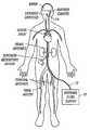
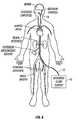
- FIG. 8is a schematic representation of the invention being used in one embodiment to cool the brain of a patient.
- the temperature of a selected organmay be intravascularly regulated by a heat transfer element placed in the organ's feeding artery to absorb or deliver heat to or from the blood flowing into the organ. While the method is described with respect to blood flow into an organ, it is understood that heat transfer within a volume of tissue is analogous. In the latter case, heat transfer is predominantly by conduction.
- the heat transfermay cause either a cooling or a heating of the selected organ.
- a heat transfer element that selectively alters the temperature of an organshould be capable of providing the necessary heat transfer rate to produce the desired cooling or heating effect within the organ to achieve a desired temperature.
- the heat transfer elementshould be small and flexible enough to fit within the feeding artery while still allowing a sufficient blood flow to reach the organ in order to avoid ischemic organ damage.
- Feeding arterieslike the carotid artery, branch off the aorta at various levels. Subsidiary arteries continue to branch off these initial branches.
- the internal carotid arterybranches off the common carotid artery near the angle of the jaw.
- the heat transfer elementis typically inserted into a peripheral artery, such as the femoral artery, using a guide catheter or guide wire, and accesses a feeding artery by initially passing though a series of one or more of these branches.
- the flexibility and size, e.g., the diameter, of the heat transfer elementare important characteristics. This flexibility is achieved as is described in more detail below.
- the common carotid arterysupplies blood to the head and brain.
- the internal carotid arterybranches off the common carotid artery to supply blood to the anterior cerebrum.
- the heat transfer elementmay be placed into the common carotid artery or into both the common carotid artery and the internal carotid artery.
- hypothermiaThe benefits of hypothermia described above are achieved when the temperature of the blood flowing to the brain is reduced to between 30° C. and 32° C.
- a typical brainhas a blood flow rate through each carotid artery (right and left) of approximately 250-375 cubic centimeters per minute (cc/min). With this flow rate, calculations show that the heat transfer element should absorb approximately 75-175 watts of heat when placed in one of the carotid arteries to induce the desired cooling effect. Smaller organs may have less blood flow in their respective supply arteries and may require less heat transfer, such as about 25 watts.
- the methodemploys conductive and convective heat transfers. Once the materials for the device and a working fluid are chosen, the conductive heat transfers are solely dependent on the temperature gradients. Convective heat transfers, by contrast, also rely on the movement of fluid to transfer heat. Forced convection results when the heat transfer surface is in contact with a fluid whose motion is induced (or forced) by a pressure gradient, area variation, or other such force. In the case of arterial flow, the beating heart provides an oscillatory pressure gradient to force the motion of the blood in contact with the heat transfer surface.
- One of the aspects of the deviceuses turbulence to enhance this forced convective heat transfer.
- ⁇ overscore (h c ) ⁇is sometimes called the “surface coefficient of heat transfer” or the “convection heat transfer coefficient”.
- the magnitude of the heat transfer rate Q to or from the fluid flowcan be increased through manipulation of the above three parameters. Practical constraints limit the value of these parameters and how much they can be manipulated.
- the internal diameter of the common carotid arteryranges from 6 to 8 mm.
- the heat transfer element residing thereinmay not be much larger than 4 mm in diameter to avoid occluding the vessel.
- the length of the heat transfer elementshould also be limited. For placement within the internal and common carotid artery, the length of the heat transfer element is limited to about 10 cm. This estimate is based on the length of the common carotid artery, which ranges from 8 to 12 cm.
- the value of the surface area Sis limited by the physical constraints imposed by the size of the artery into which the device is placed.
- Surface featuressuch as fins, can be used to increase the surface area of the heat transfer element, however, these features alone cannot provide enough surface area enhancement to meet the required heat transfer rate to effectively cool the brain.
- the allowable surface temperature of the heat transfer elementis limited by the characteristics of blood.
- the blood temperatureis fixed at about 37° C., and blood freezes at approximately 0° C. When the blood approaches freezing, ice emboli may form in the blood which may lodge downstream, causing serious ischemic injury.
- reducing the temperature of the bloodalso increases its viscosity which results in a small decrease in the value of ⁇ overscore (h c ) ⁇ .
- Increased viscosity of the bloodmay further result in an increase in the pressure drop within the artery, thus compromising the flow of blood to the brain.
- the heat transfer rate Q no-flow in the absence of fluid flowis proportional to ⁇ T, the temperature differential between the surface temperature T s of the heat transfer element and the free stream blood temperature T b times k, the diffusion constant, and is inversely proportion to ⁇ , the thickness of the boundary layer.
- Nusselt numbersFor convective heat transfer between blood and the surface of the heat transfer element, Nusselt numbers of 30-80 have been found to be appropriate for selective cooling applications of various organs in the human body. Nusselt numbers are generally dependent on several other numbers: the Reynolds number, the Womersley number, and the Prandtl number.
- Stirring-type mechanismswhich abruptly change the direction of velocity vectors, may be utilized to induce turbulent kinetic energy and increase the heat transfer rate.
- the level of turbulence so createdis characterized by the turbulence intensity .
- Turbulence intensityis defined as the root mean square of the fluctuating velocity divided by the mean velocity.
- Such mechanismscan create high levels of turbulence intensity in the free stream, thereby increasing the heat transfer rate.
- This turbulence intensityshould ideally be sustained for a significant portion of the cardiac cycle, and should ideally be created throughout the free stream and not just in the boundary layer.
- Turbulencedoes occur for a short period in the cardiac cycle anyway.
- the blood flowis turbulent during a small portion of the descending systolic flow. This portion is less than 20% of the period of the cardiac cycle.
- the turbulence intensityis at least 0.05.
- the instantaneous velocity fluctuationsdeviate from the mean velocity by at least 5%.
- the heat transfer elementis made of a high thermal conductivity material, such as metal.
- the use of a highly thermally conductive materialincreases the heat transfer rate for a given temperature differential between the coolant within the heat transfer element and the blood. This facilitates the use of a higher temperature coolant within the heat transfer element, allowing safer coolants, such as water, to be used.
- FIG. 1is a perspective view of such a turbulence inducing heat transfer element within an artery. Turbulent flow would be found at point 114 , in the free stream area.
- the abrupt changes in flow directionare achieved through the use of a series of two or more heat transfer segments, each comprised of one or more helical ridges. To affect the free stream, the depth of the helical ridge is larger than the thickness of the boundary layer which would develop if the heat transfer element had a smooth cylindrical surface.
- FIG. 2is an elevation view of one embodiment of a heat transfer element 14 .
- the heat transfer element 14is comprised of a series of elongated, articulated segments or modules 20 , 22 , 24 . Three such segments are shown in this embodiment, but two or more such segments could be used.
- a first elongated heat transfer segment 20is located at the proximal end of the heat transfer element 14 .
- a turbulence-inducing exterior surface of the segment 20comprises four parallel helical ridges 28 with four parallel helical grooves 26 therebetween.
- One, two, three, or more parallel helical ridges 28could also be used.
- the helical ridges 28 and the helical grooves 26 of the heat transfer segment 20have a left hand twist, referred to herein as a counter-clockwise spiral or helical rotation, as they proceed toward the distal end of the heat transfer segment 20 .
- the first heat transfer segment 20is coupled to a second elongated heat transfer segment 22 by a first bellows section 25 , which provides flexibility and compressibility.
- the second heat transfer segment 22comprises one or more helical ridges 32 with one or more helical grooves 30 therebetween.
- the ridges 32 and grooves 30have a right hand, or clockwise, twist as they proceed toward the distal end of the heat transfer segment 22 .
- the second heat transfer segment 22is coupled to a third elongated heat transfer segment 24 by a second bellows section 27 .
- the third heat transfer segment 24comprises one or more helical ridges 36 with one or more helical grooves 34 therebetween.
- the helical ridge 36 and the helical groove 34have a left hand, or counter-clockwise, twist as they proceed toward the distal end of the heat transfer segment 24 .
- successive heat transfer segments 20 , 22 , 24 of the heat transfer element 14alternate between having clockwise and counterclockwise helical twists.
- the actual left or right hand twist of any particular segmentis immaterial, as long as adjacent segments have opposite helical twist.
- a heat transfer elementmay be comprised of two, three, or more heat transfer segments.
- the bellows sections 25 , 27are formed from seamless and nonporous materials, such as metal, and therefore are impermeable to gas, which can be particularly important, depending on the type of working fluid which is cycled through the heat transfer element 14 .
- the structure of the bellows sections 25 , 27allows them to bend, extend and compress, which increases the flexibility of the heat transfer element 14 so that it is more readily able to navigate through blood vessels.
- the bellows sections 25 , 27also provide for axial compression of the heat transfer element 14 , which can limit the trauma when the distal end of the heat transfer element 14 abuts a blood vessel wall.
- the bellows sections 25 , 27are also able to tolerate cryogenic temperatures without a loss of performance.
- the exterior surfaces of the heat transfer element 14can be made from metal, and may comprise very high thermal conductivity materials such as nickel, thereby facilitating heat transfer.
- metalssuch as stainless steel, titanium, aluminum, silver, copper and the like, can be used, with or without an appropriate coating or treatment to enhance biocompatibility or inhibit clot formation.
- Suitable biocompatible coatingsinclude, e.g., gold, platinum or polymer paralyene.
- the heat transfer element 14may be manufactured by plating a thin layer of metal on a mandrel that has the appropriate pattern. In this way, the heat transfer element 14 may be manufactured inexpensively in large quantities, which is an important feature in a disposable medical device.
- the heat transfer element 14may dwell within the blood vessel for extended periods of time, such as 24-48 hours or even longer, it may be desirable to treat the surfaces of the heat transfer element 14 to avoid clot formation.
- One means by which to prevent thrombus formationis to bind an antithrombogenic agent to the surface of the heat transfer element 14 .
- heparinis known to inhibit clot formation and is also known to be useful as a biocoating.
- the surfaces of the heat transfer element 14may be bombarded with ions such as nitrogen. Bombardment with nitrogen can harden and smooth the surface and, thus prevent adherence of clotting factors to the surface.
- FIG. 3is a longitudinal sectional view of the heat transfer element 14 , taken along line 3 — 3 in FIG. 2 . Some interior contours are omitted for purposes of clarity.
- An inner tube 42creates an inner coaxial lumen 42 and an outer coaxial lumen 46 within the heat transfer element 14 .
- a working fluidsuch as saline or other aqueous solution may be circulated through the heat transfer element 14 . Fluid flows up a supply catheter into the inner coaxial lumen 40 . At the distal end of the heat transfer element 14 , the working fluid exits the inner coaxial lumen 40 and enters the outer lumen 46 .
- the tube 42may be formed as an insulating divider to thermally separate the inner lumen 40 from the outer lumen 46 .
- insulationmay be achieved by creating longitudinal air channels in the wall of the insulating tube 42 .
- the insulating tube 42may be constructed of a non-thermally conductive material like polytetrafluoroethylene or some other polymer.
- the same mechanisms that govern the heat transfer rate between the exterior surface 37 of the heat transfer element 14 and the bloodalso govern the heat transfer rate between the working fluid and the interior surface 38 of the heat transfer element 14 .
- the heat transfer characteristics of the interior surface 38are particularly important when using water, saline or other fluid which remains a liquid as the coolant.
- Other coolantssuch as freon undergo nucleate boiling and create turbulence through a different mechanism.
- Salineis a safe coolant because it is non-toxic, arid leakage of saline does not result in a gas embolism, which could occur with the use of boiling refrigerants. Since turbulence in the coolant is enhanced by the shape of the interior surface 38 of the heat transfer element 14 , the coolant can be delivered to the heat transfer element 14 at a warmer temperature and still achieve the necessary heat transfer rate.
- the catheter shaft diametercan be made smaller.
- the enhanced heat transfer characteristics of the interior surface of the heat transfer element 14also allow the working fluid to be delivered to the heat transfer element 14 at lower flow rates and lower pressures. High pressures may make the heat transfer element stiff and cause it to push against the wall of the blood vessel, thereby shielding part of the exterior surface 37 of the heat transfer element 14 from the blood. Because of the increased heat transfer characteristics achieved by the alternating helical ridges 28 , 32 , 36 , the pressure of the working fluid may be as low as 5 atmospheres, 3 atmospheres, 2 atmospheres or even less than 1 atmosphere.
- FIG. 4is a transverse sectional view of the heat transfer element 14 , taken at a location denoted by the line 4 — 4 in FIG. 2 .
- FIG. 4illustrates a five lobed embodiment, whereas FIG. 2 illustrates a four-lobed embodiment. As mentioned earlier, any number of lobes might be used.
- the inner coaxial lumen 40is defined by the insulating coaxial tube 42 .
- the outer lumen 46is defined by the exterior surface of the insulating coaxial tube 42 and the interior surface 38 of the heat transfer element 14 .
- the helical ridges 32 and helical grooves 30may be seen in FIG. 4 .
- the depth of the grooves, diis greater than the boundary layer thickness which would have developed if a cylindrical heat transfer element were introduced.
- the depth of the invaginations, d imay be approximately equal to 1 mm if designed for use in the carotid artery.
- FIG. 4shows four ridges and four grooves, the number of ridges and grooves may vary.
- heat transfer elementswith 1, 2, 3, 4, 5, 6, 7, 8 or more ridges are specifically contemplated.
- FIG. 5is a perspective view of a heat transfer element 14 in use within a blood vessel, showing only one helical lobe per segment for purposes of clarity.
- the first helical heat transfer segment 20induces a counter-clockwise rotational inertia to the blood.
- the rotational direction of the inertiais reversed, causing turbulence within the blood.
- the rotational direction of the inertiais again reversed.
- the sudden changes in flow directionactively reorient and randomize the velocity vectors, thus ensuring turbulence throughout the bloodstream.
- the velocity vectors of the bloodbecome more random and, in some cases, become perpendicular to the axis of the artery.
- additional turbulenceis induced and turbulent motion is sustained throughout the duration of each pulse through the same mechanisms described above.
- the heat transfer element 14creates a turbulence intensity greater than about 0.05.
- the turbulence intensitymay be greater than 0.05, 0.06, 0.07 or up to 0.10 or 0.20 or greater.
- the heat transfer element 14has been designed to address all of the design criteria discussed above.
- the heat transfer element 14is flexible and is made of a highly conductive material. The flexibility is provided by a segmental distribution of bellows sections 25 , 27 which provide an articulating mechanism. Bellows have a known convoluted design which provides flexibility.
- the exterior surface area 37has been increased through the use of helical ridges 28 , 32 , 36 and helical grooves 26 , 30 , 34 . The ridges also allow the heat transfer element 14 to maintain a relatively atraumatic profile, thereby minimizing the possibility of damage to the vessel wall.
- the heat transfer element 14has been designed to promote turbulent kinetic energy both internally and externally.
- the modular or segmental designallows the direction of the invaginations to be reversed between segments.
- the alternating helical rotationscreate an alternating flow that results in mixing the blood in a manner analogous to the mixing action created by the rotor of a washing machine that switches directions back and forth. This mixing action is intended to promote high level turbulent kinetic energy to enhance the heat transfer rate.
- the alternating helical designalso causes beneficial mixing, or turbulent kinetic energy, of the working fluid flowing internally.
- FIG. 6is a cut-away perspective view of an alternative embodiment of a heat transfer element 50 .
- An external surface 52 of the heat transfer element 50is covered with a series of axially staggered protrusions 54 .
- the staggered nature of the outer protrusions 54is readily seen with reference to FIG. 7 which is a transverse crosssectional view taken at a location denoted by the line 7 — 7 in FIG. 6 .
- the height, d pof the staggered outer protrusions 54 is greater than the thickness of the boundary layer which would develop if a smooth heat transfer element had been introduced into the blood stream.
- a working fluidis circulated up through an inner coaxial lumen 56 defined by an insulating coaxial tube 58 to a distal tip of the heat transfer element 50 .
- the working fluidthen traverses an outer coaxial lumen 60 in order to transfer heat to the exterior surface 52 of the heat transfer element 50 .
- the inside surface of the heat transfer element 50is similar to the exterior surface 52 , in order to induce turbulent flow of the working fluid.
- the inner protrusionscan be aligned with the outer protrusions 54 , as shown in FIG. 7, or they can be offset from the outer protrusions 54 , as shown in FIG. 6 .
- FIG. 8is a schematic representation of the invention being used to cool the brain of a patient.
- the selective organ hypothermia apparatus shown in FIG. 8includes a working fluid supply 10 , preferably supplying a chilled liquid such as water, alcohol or a halogenated hydrocarbon, a supply catheter 12 and the heat transfer element 14 .
- the supply catheter 12has a coaxial construction.
- An inner coaxial lumen within the supply catheter 12receives coolant from the working fluid supply 10 .
- the coolanttravels the length of the supply catheter 12 to the heat transfer element 14 which serves as the cooling tip of the catheter.
- the coolantexits the insulated interior lumen and traverses the length of the heat transfer element 14 in order to decrease the temperature of the heat transfer element 14 .
- the coolantthen traverses an outer lumen of the supply catheter 12 so that it may be disposed of or recirculated.
- the supply catheter 12is a flexible catheter having a diameter sufficiently small to allow its distal end to be inserted percutaneously into an accessible artery such as the femoral artery of a patient as shown in FIG. 8 .
- the supply catheter 12is sufficiently long to allow the heat transfer element 14 at the distal end of the supply catheter 12 to be passed through the vascular system of the patient and placed in the internal carotid artery or other small artery.
- the method of inserting the catheter into the patient and routing the heat transfer element 14 into a selected arteryis well known in the art.
- working fluid supply 10is shown as an exemplary cooling device, other devices and working fluids may be used.
- freon, perflourocarbon, water, or salinemay be used, as well as other such coolants.
- the heat transfer elementcan absorb or provide over 75 Watts of heat to the blood stream and may absorb or provide as much as 100 Watts, 150 Watts, 170 Watts or more.
- a heat transfer element with a diameter of 4 mm and a length of approximately 10 cm using ordinary saline solution chilled so that the surface temperature of the heat transfer element is approximately 5° C. and pressurized at 2 atmospherescan absorb about 100 Watts of energy from the bloodstream.
- Smaller geometry heat transfer elementsmay be developed for use with smaller organs which provide 60 Watts, 50 Watts, 25 Watts or less of heat transfer.
- the patientis initially assessed, resuscitated, and stabilized.
- the procedureis carried out in an angiography suite or surgical suite equipped with flouroscopy.
- a carotid duplex (doppler/ultrasound) scancan quickly and non-invasively make this determinations.
- the ideal location for placement of the catheteris in the left carotid so this may be scanned first. If disease is present, then the right carotid artery can be assessed. This test can be used to detect the presence of proximal common carotid lesions by observing the slope of the systolic upstroke and the shape of the pulsation. Although these lesions are rare, they could inhibit the placement of the catheter.
- Peak blood flow velocities in the internal carotidcan determine the presence of internal carotid artery lesions. Although the catheter is placed proximally to such lesions, the catheter may exacerbate the compromised blood flow created by these lesions. Peak systolic velocities greater that 130 cm/sec and peak diastolic velocities greater than about 100 cm/sec in the internal indicate the presence of at least 70% stenosis. Stenosis of 70% or more may warrant the placement of a stent to open up the internal artery diameter.
- the ultrasoundcan also be used to determine the vessel diameter and the blood flow and the catheter with the appropriately sized heat transfer element could be selected.
- the patients inguinal regionis sterilely prepped and infiltrated with lidocaine.
- the femoral arteryis cannulated and a guide wire may be inserted to the desired carotid artery. Placement of the guide wire is confirmed with flouroscopy.
- An angiographic cathetercan be fed over the wire and contrast media injected into the artery to further to assess the anatomy of the carotid.
- the femoral arteryis cannulated and a 10-12.5 french (f) introducer sheath is placed.
- a guide catheteris placed into the desired common carotid artery. If a guiding catheter is placed, it can be used to deliver contrast media directly to further assess carotid anatomy.
- a 10 f-12 f (3.3-4.0 mm) (approximate) cooling catheteris subsequently filled with saline and all air bubbles are removed.
- the cooling catheteris placed into the carotid artery via the guiding catheter or over the guidewire. Placement is confirmed with flouroscopy.
- the cooling catheter tipis shaped (angled or curved approximately 45 degrees), and the cooling catheter shaft has sufficient pushability and torqueability to be placed in the carotid without the aid of a guide wire or guide catheter.
- the cooling catheteris connected to a pump circuit also filled with saline and free from air bubbles.
- the pump circuithas a heat exchange section that is immersed into a water bath and tubing that is connected to a peristaltic pump. The water bath is chilled to approximately 0 20 C.
- Coolingis initiated by starting the pump mechanism.
- the saline within the cooling catheteris circulated at 5 cc/sec.
- the salinetravels through the heat exchanger in the chilled water bath and is cooled to approximately 1° C.
- the salineis warmed to approximately 5-7° C. as it travels along the inner lumen of the catheter shaft to the end of the heat transfer element.
- the salinethen flows back through the heat transfer element in contact with the inner metallic surface.
- the salineis further warmed in the heat transfer element to 12-15° C., and in the process, heat is absorbed from the blood, cooling the blood to 30° C. to 32° C.
- the warmed salinetravels back down the outer lumen of the catheter shaft and back to the chilled water bath where it is cooled to 1° C.
- the pressure drops along the length of the circuitare estimated to be 2-3 atmospheres.
- the coolingcan be adjusted by increasing or decreasing the flow rate of the saline. Monitoring of the temperature drop of the saline along the heat transfer element will allow the flow to be adjusted to maintain the desired cooling effect.
- the catheteris left in place to provide cooling for 12 to 24 hours.
- warm salinecan be circulated to promote warming of the brain at the end of the therapeutic cooling period.
- the above devices and techniquesprovide effective cooling or heating of a fluid such as blood.
- the heating or coolingmay occur either in the affected vessel or in a vessel in fluid communication with the affected vessel.
- fluid communicationbetween two vessels refers to a situation where one vessel either feeds or is fed by the other.
- One application of these devices and techniquesis for clot lysis.
- other types of enzyme activationsmay also be advantageously induced.
- the method disclosed belowis applicable to other devices and techniques so long as they are also capable of heating or cooling blood.
- enzymeshave been delivered to patients in drug or intravenous form for clot lysing. These enzymes are in addition to naturally occurring enzymes already in the blood plasma.
- the activity of enzymesis at least partially adjusted by control of environmental temperature.
- a method according to an embodiment of the inventionselectively controls enzyme activity by controlling the temperature of the environment of the enzyme. This controlled enzyme activity allows selective thrombolysis by selective vessel hypothermia in a manner described in more detail below.
- Plasminogenis the inert precursor of plasmin.
- Plasminis an enzyme that lyses clots, i.e., cleaves peptide bonds in fibrin. Plasminogen binds to fibrin and, when activated by an appropriate enzyme, such as tPA, UK, SK, etc., converts to plasmin. Plasminogen may also be activated in solution.
- Inhibitorssuch as ⁇ 2 -antiplasmin moderate plasmin activity by inactivating plasmin released from a fibrin surface almost instantaneously. ⁇ 2 -antiplasmin can even inactivate plasmin bound to a fibrin surface, but this process requires about 10 seconds.
- ⁇ 2 -antiplasminis lessened at low temperatures and thus is less effective at inactivating plasmin. In this case, more plasmin is available to lyse clots and thus fibrinolysis is enhanced.
- a related effectis due to the effect of plasmin levels on plasminogen levels. Increased plasmin levels may lead to increased plasminogen levels circulating in solution. Moreover, decreased activity of ⁇ 2 -antiplasmin also leads to increased plasminogen levels because ⁇ 2 -antiplasmin binds plasminogen, and less ⁇ 2 -antiplasmin means less of such binding.
- plasmincleaves single-chain urokinase (“scu-PA” or “pro-UK”) to form UK, i.e., pro-UK is a precursor to UK.
- Pro-UKlike tPA, cannot efficiently activate plasminogen in solution, but it can readily activate plasminogen bound to fibrin.
- increased plasminogen, together with the body's own UK or tPA, or similar enzymes provided intravenously,may result in more localized lysing of fibrin, e.g., directly at the clot situs.
- Plasminmay stay bound to fibrin for a longer period in the hypothermic state. Thus, more time may be available to lyse clots, increasing overall fibrinolysis.
- hypothermic temperatures at which increased fibrinolysis occurshave not been fully explored. However, it has been shown that clot samples have benefited from temperatures of, e.g., 25° C. or below. For human patients, it is believed that temperatures of 30° C. to 32° C. may well be appropriate and advantageously employed in the method of the invention.
- the methodmay further employ a step of rewarming the cooled organ from the low temperature of, e.g., 30° C.
- the temperature range for rewarmingmay be from about 20° C. to 37° C. depending on the patient, the condition, the hypothermic temperature, and so on. Rewarming has been shown to have a beneficial effect in certain studies, perhaps by increasing the rate at which clot lysis occurs.
- the methodmay further employ temperature cycling the blood in the vessel from a hypothermic temperature to a rewarmed temperature. In this way, the rewarming temperature regime is achieved repeatedly and thus so is the enhanced fibrinolysis.
- clot lysis in dogswas investigated while varying clot temperatures in a range of 20° C. to 36° C.
- the dog's temperaturewas lowered from a normal temperature to a low temperature.
- a gradual rewarming periodfollowed the low temperature period.
- Enhanced clot lysiswas observed at lower temperatures as compared to higher temperatures.
- the maximum fibrinolytic activityoccurred in the early rewarming period, i.e., from 20° C. to about 25° C. It is believed that this study can be extended to humans, and that fibrinolytic activity can be enhanced at lower temperatures, especially during periods of rewarming.
- clot lysiscan be achieved in a simple manner and without the need for drugs.
- An additional advantageresults from the reduced temperature of the blood which helps to protect the cells from ischemia at the same time lysis is occurring.
- clot lysis and coolingoccur simultaneously, providing an effective and aggressive dual therapy.
- dual therapiesare employed, cooling catheters may be inserted in both femoral arteries for transit to the brain. One cooling catheter cools the brain, while the other cools the blood in the artery leading to the clot. The latter provides the beneficial effects noted above.
- thrombolytic drugssuch as those disclosed above, may be introduced to induce the fibrinolysis.
- hypothermiais induced as a neuroprotective measure, and may further induce clot lysing per se in the manner described above.
- a difficulty with this approachis that the techniques are interdependent. Drugs depend on enzymes for their activity, and enzymes are temperature-dependent. In fact, past studies have demonstrated that the enzyme activity of these specific thrombolytic drugs on clot samples is temperature-dependent. In other words, their effect on clot or thrombus lysis varies over a temperature range. For typical temperature-specific enzymes, the greatest activity occurs at an optimal temperature.
- the optimal temperaturemay be about 37° C. in the case of known thrombolytics, as this is the normal human body temperature.
- Enzyme activitydrastically reduces above certain temperatures as the enzyme denatures and becomes inactive. At the opposite extreme, enzyme activity reduces below certain temperatures as the enzyme lacks the energy necessary to couple to a substrate. Therefore, when the brain or other tissue is at a temperature different from normal body temperature, e.g., during hypothermia, an isoform of the enzyme is preferably used which has an optimal working temperature at the hypothermic body temperature. In this disclosure, such an isoform which is effective at a different temperature is said to have a “working temperature” at the different temperature or within a range of different temperatures.
- the term “isoforn” of an enzymeis used as follows. If a first enzyme catalyzes a reaction at a first temperature, and a different enzyme catalyzes the same reaction at a second temperature, then the different enzyme is an “isoform” of the first enzyme within the meaning intended here.
- the physicianmay preferably use a low-temperature isoform; for patients whose temperatures have been raised, the physician may preferably use a high-temperature isoform.
- the form of the enzymewill preferably have an optimal activity curve at or near the desired temperature. Known enzymes are described below, followed by a methodology for choosing enzymes which are not yet known.
- a cooling cathetermay be placed in an artery supplying blood to a thrombosed vessel.
- the cathetermay include a separate lumen through which the SK mixture may be delivered.
- a coolant or working fluidmay be supplied to the cooling catheter, causing the same to cool and to cool the blood adjacent a heat transfer element located at a distal tip of the cooling catheter.
- This cooling stepmay include the step of inducing turbulence in the blood flowing through the vessel and/or in the working fluid.
- SKmay be delivered through the separate drug delivery lumen. The patient may then be rewarmed as the SK is delivered. The rewarming step may be accomplished by passing a warm saline solution as the working fluid.
- patientsmay be provided with tPA and may undergo hypothermia using an above device placed in an artery supplying blood to a thrombosed vessel.
- the cathetermay include a separate lumen through which tPA may be delivered.
- a coolant or working fluidmay be supplied to the cooling catheter, causing the catheter and the adjacent blood to cool.
- This cooling stepmay include the step of inducing turbulence in the blood flowing in the vessel and/or in the working fluid.
- tPAmay be delivered through the separate drug delivery lumen. In this case, the patient may not be rewarmed until the drug delivery is complete, or until the thrombus is dissolved.
- an embodiment of the method of the inventionmay be employed to advantageously perform either heating or cooling in an improved way.
- a warm saline solutionmay be provided in a catheter of the type described above.
- the warm saline solutiontransfers heat to the blood at a heat transfer element.
- An appropriate temperature range for the warm saline solution at a point within the heat transfer elementmay be about 38° C. to 74° C.
- a cooling cathetermay be inserted in one femoral artery for transit to the brain for neural protection.
- a heating catheterwould be employed if a temperature rise were desired.
- Another cathetermay provide the drug delivery.
- the heating or cooling cathetermay have disposed therein a lumen for drug delivery.
- an appropriate isoform of an enzymemay be employed to allow enzymatic activity at temperatures other than normal body temperature.
- One way to choose appropriate isoforms for these enzymesis by searching for the same in cold climates.
- SKis a bacterial enzyme. Bacteria live in many different temperature environments. It is common to find or select an enzyme for a certain process or temperature by finding bacteria that live in environments having the desired temperature.
- the polymerase chain reactionis a polynucleotide amplification process that requires an enzyme capable of surviving high temperatures.
- These enzymeswere located in bacteria living in hot springs and thermal vents on the sea floor. Therefore, it is likely that certain bacteria that live in room temperature environments or arctic-like environments will have enzymes similar to those desired, i.e., SK that can survive hypothermic environments.
- tPA and UKare recombinant forms of human enzymes.
- tPA and UKcould be genetically altered to maintain their activity at lower temperatures.
- the protein backbonecould be changed to yield higher tPA or UK activity at lower temperatures.
- the inventionhas been described predominantly with respect to a particular lysing system: the lysing of a blood clot in a blood vessel such as is caused by stroke or myocardial infarction.
- the methods of the inventioncan be equally applied to altering the activity of any enzyme relative to its activity at normal temperatures.
- the inventionmay be applied to cooling solids, such as volumes of tissue, rather than blood flows or static volumes of blood.
- the inventioncan be applied to heating blood or tissue, especially when such heating advantageously enhances desired activity in a specific enzyme.
Landscapes
- Health & Medical Sciences (AREA)
- Life Sciences & Earth Sciences (AREA)
- Public Health (AREA)
- Surgery (AREA)
- Engineering & Computer Science (AREA)
- Biomedical Technology (AREA)
- Heart & Thoracic Surgery (AREA)
- Veterinary Medicine (AREA)
- Animal Behavior & Ethology (AREA)
- General Health & Medical Sciences (AREA)
- Nuclear Medicine, Radiotherapy & Molecular Imaging (AREA)
- Anesthesiology (AREA)
- Hematology (AREA)
- Pulmonology (AREA)
- Biophysics (AREA)
- Otolaryngology (AREA)
- Medical Informatics (AREA)
- Molecular Biology (AREA)
- Physics & Mathematics (AREA)
- Thermal Sciences (AREA)
- Vascular Medicine (AREA)
- Thermotherapy And Cooling Therapy Devices (AREA)
Abstract
Description
Claims (5)
Priority Applications (10)
| Application Number | Priority Date | Filing Date | Title |
|---|---|---|---|
| US09/714,749US6468296B1 (en) | 1998-01-23 | 2000-11-16 | Method for low temperature thrombolysis and low temperature thrombolytic agent with selective organ temperature control |
| US10/216,487US6830581B2 (en) | 1999-02-09 | 2002-08-09 | Method and device for patient temperature control employing optimized rewarming |
| US10/216,405US6869440B2 (en) | 1999-02-09 | 2002-08-09 | Method and apparatus for patient temperature control employing administration of anti-shivering agents |
| US10/219,874US6974463B2 (en) | 1999-02-09 | 2002-08-14 | System and method for patient temperature control employing temperature projection algorithm |
| US10/767,782US7458984B2 (en) | 1998-01-23 | 2004-01-28 | System and method for inducing hypothermia with active patient temperature control employing catheter-mounted temperature sensor and temperature projection algorithm |
| US10/925,043US7189254B2 (en) | 1999-02-09 | 2004-08-24 | Method and device for patient temperature control employing optimized rewarming |
| US11/003,220US7351254B2 (en) | 1999-02-09 | 2004-12-03 | Method and device for patient temperature control employing optimized rewarming |
| US11/085,700US7422600B2 (en) | 1999-02-09 | 2005-03-21 | Method and apparatus for patient temperature control employing administration of anti-shivering agents |
| US11/299,708US7914564B2 (en) | 1999-02-09 | 2005-12-12 | System and method for patient temperature control employing temperature projection algorithm |
| US12/060,790US8343202B2 (en) | 1999-02-09 | 2008-04-01 | Method and device for patient temperature control employing optimized rewarming |
Applications Claiming Priority (6)
| Application Number | Priority Date | Filing Date | Title |
|---|---|---|---|
| US09/012,287US6051019A (en) | 1998-01-23 | 1998-01-23 | Selective organ hypothermia method and apparatus |
| US09/047,012US5957963A (en) | 1998-01-23 | 1998-03-24 | Selective organ hypothermia method and apparatus |
| US09/052,545US6231595B1 (en) | 1998-03-31 | 1998-03-31 | Circulating fluid hypothermia method and apparatus |
| US09/103,342US6096068A (en) | 1998-01-23 | 1998-06-23 | Selective organ cooling catheter and method of using the same |
| US09/215,039US6251129B1 (en) | 1998-03-24 | 1998-12-16 | Method for low temperature thrombolysis and low temperature thrombolytic agent with selective organ temperature control |
| US09/714,749US6468296B1 (en) | 1998-01-23 | 2000-11-16 | Method for low temperature thrombolysis and low temperature thrombolytic agent with selective organ temperature control |
Related Parent Applications (3)
| Application Number | Title | Priority Date | Filing Date |
|---|---|---|---|
| US09/215,039DivisionUS6251129B1 (en) | 1998-01-23 | 1998-12-16 | Method for low temperature thrombolysis and low temperature thrombolytic agent with selective organ temperature control |
| US09/621,051Continuation-In-PartUS6582455B1 (en) | 1998-01-23 | 2000-07-21 | Method and device for applications of selective organ cooling |
| US65895000AContinuation-In-Part | 1998-01-23 | 2000-09-11 |
Related Child Applications (4)
| Application Number | Title | Priority Date | Filing Date |
|---|---|---|---|
| US09/757,124Continuation-In-PartUS6540771B2 (en) | 1998-01-23 | 2001-01-08 | Inflatable catheter for selective organ heating and cooling and method of using the same |
| US10/216,405Continuation-In-PartUS6869440B2 (en) | 1999-02-09 | 2002-08-09 | Method and apparatus for patient temperature control employing administration of anti-shivering agents |
| US10/216,487Continuation-In-PartUS6830581B2 (en) | 1999-02-09 | 2002-08-09 | Method and device for patient temperature control employing optimized rewarming |
| US10/219,874Continuation-In-PartUS6974463B2 (en) | 1998-01-23 | 2002-08-14 | System and method for patient temperature control employing temperature projection algorithm |
Publications (1)
| Publication Number | Publication Date |
|---|---|
| US6468296B1true US6468296B1 (en) | 2002-10-22 |
Family
ID=46256220
Family Applications (3)
| Application Number | Title | Priority Date | Filing Date |
|---|---|---|---|
| US09/215,039Expired - LifetimeUS6251129B1 (en) | 1998-01-23 | 1998-12-16 | Method for low temperature thrombolysis and low temperature thrombolytic agent with selective organ temperature control |
| US09/714,749Expired - LifetimeUS6468296B1 (en) | 1998-01-23 | 2000-11-16 | Method for low temperature thrombolysis and low temperature thrombolytic agent with selective organ temperature control |
| US09/714,893Expired - LifetimeUS6478811B1 (en) | 1998-01-23 | 2000-11-16 | Method for low temperature thrombolysis and low temperature thrombolytic agent with selective organ temperature control |
Family Applications Before (1)
| Application Number | Title | Priority Date | Filing Date |
|---|---|---|---|
| US09/215,039Expired - LifetimeUS6251129B1 (en) | 1998-01-23 | 1998-12-16 | Method for low temperature thrombolysis and low temperature thrombolytic agent with selective organ temperature control |
Family Applications After (1)
| Application Number | Title | Priority Date | Filing Date |
|---|---|---|---|
| US09/714,893Expired - LifetimeUS6478811B1 (en) | 1998-01-23 | 2000-11-16 | Method for low temperature thrombolysis and low temperature thrombolytic agent with selective organ temperature control |
Country Status (1)
| Country | Link |
|---|---|
| US (3) | US6251129B1 (en) |
Cited By (31)
| Publication number | Priority date | Publication date | Assignee | Title |
|---|---|---|---|---|
| US6585752B2 (en) | 1998-06-23 | 2003-07-01 | Innercool Therapies, Inc. | Fever regulation method and apparatus |
| US6595967B2 (en) | 2001-02-01 | 2003-07-22 | Innercool Therapies, Inc. | Collapsible guidewire lumen |
| US6648908B2 (en) | 1998-01-23 | 2003-11-18 | Innercool Therapies, Inc. | Inflatable catheter for selective organ heating and cooling and method of using the same |
| US20040220619A1 (en)* | 2001-06-27 | 2004-11-04 | Chuwa Tei | Method of inhibiting the proliferation of vascular smooth muscle cells |
| US6979345B2 (en) | 2000-12-06 | 2005-12-27 | Innercool Therapies, Inc. | Multipurpose catheter assembly |
| US7181927B2 (en) | 2005-07-01 | 2007-02-27 | Alsius Corporation | Primary heat exchanger for patient temperature control |
| US7371254B2 (en) | 1998-01-23 | 2008-05-13 | Innercool Therapies, Inc. | Medical procedure |
| US7425216B2 (en) | 2005-03-01 | 2008-09-16 | Alsius Corporation | System and method for treating cardiac arrest and myocardial infarction |
| US20090251228A1 (en)* | 2008-04-03 | 2009-10-08 | Sony Corporation | Voltage-controlled variable frequency oscillation circuit and signal processing circuit |
| US7822485B2 (en) | 2006-09-25 | 2010-10-26 | Zoll Circulation, Inc. | Method and apparatus for spinal cooling |
| US7857781B2 (en) | 1998-04-21 | 2010-12-28 | Zoll Circulation, Inc. | Indwelling heat exchange catheter and method of using same |
| US7867266B2 (en) | 2006-11-13 | 2011-01-11 | Zoll Circulation, Inc. | Temperature management system with assist mode for use with heart-lung machine |
| US7892269B2 (en) | 2005-04-18 | 2011-02-22 | Zoll Circulation, Inc. | External heat exchange pad for patient |
| US7892270B2 (en) | 2006-11-21 | 2011-02-22 | Zoll Circulation Inc. | Temperature management system and method for burn patients |
| US7942871B2 (en) | 2006-05-12 | 2011-05-17 | Vytronus, Inc. | Device for ablating body tissue |
| US7951182B2 (en) | 2005-07-14 | 2011-05-31 | Zoll Circulation, Inc. | System and method for leak detection in external cooling pad |
| US8128595B2 (en) | 1998-04-21 | 2012-03-06 | Zoll Circulation, Inc. | Method for a central venous line catheter having a temperature control system |
| US8353893B2 (en) | 2007-03-07 | 2013-01-15 | Zoll Circulation, Inc. | System and method for rapidly cooling cardiac arrest patient |
| US8414508B2 (en) | 2008-10-30 | 2013-04-09 | Vytronus, Inc. | System and method for delivery of energy to tissue while compensating for collateral tissue |
| US8475379B2 (en) | 2008-11-17 | 2013-07-02 | Vytronus, Inc. | Systems and methods for ablating body tissue |
| US20130304166A1 (en)* | 2001-02-21 | 2013-11-14 | Zoll Circulation Inc. | Inhibition of platelet activation, aggregation and/or adhesion by hypothermia |
| US9033885B2 (en) | 2008-10-30 | 2015-05-19 | Vytronus, Inc. | System and method for energy delivery to tissue while monitoring position, lesion depth, and wall motion |
| US9155588B2 (en) | 2008-06-13 | 2015-10-13 | Vytronus, Inc. | System and method for positioning an elongate member with respect to an anatomical structure |
| US9192789B2 (en) | 2008-10-30 | 2015-11-24 | Vytronus, Inc. | System and method for anatomical mapping of tissue and planning ablation paths therein |
| US9220924B2 (en) | 2008-10-30 | 2015-12-29 | Vytronus, Inc. | System and method for energy delivery to tissue while monitoring position, lesion depth, and wall motion |
| US9737692B2 (en) | 2007-05-18 | 2017-08-22 | Zoll Circulation, Inc. | System and method for effecting non-standard fluid line connections |
| US9737323B2 (en) | 2008-11-17 | 2017-08-22 | Vytronus, Inc. | Systems and methods for imaging and ablating body tissue |
| US10363057B2 (en) | 2008-07-18 | 2019-07-30 | Vytronus, Inc. | System and method for delivering energy to tissue |
| US11298568B2 (en) | 2008-10-30 | 2022-04-12 | Auris Health, Inc. | System and method for energy delivery to tissue while monitoring position, lesion depth, and wall motion |
| US11464671B2 (en) | 2017-04-07 | 2022-10-11 | Palmera Medical, Inc. | Therapeutic organ cooling |
| EP4132386A4 (en)* | 2020-04-08 | 2023-09-13 | Mayo Foundation for Medical Education and Research | Blood clot retrieval systems and methods |
Families Citing this family (97)
| Publication number | Priority date | Publication date | Assignee | Title |
|---|---|---|---|---|
| US6464716B1 (en) | 1998-01-23 | 2002-10-15 | Innercool Therapies, Inc. | Selective organ cooling apparatus and method |
| US6383210B1 (en) | 2000-06-02 | 2002-05-07 | Innercool Therapies, Inc. | Method for determining the effective thermal mass of a body or organ using cooling catheter |
| US6096068A (en) | 1998-01-23 | 2000-08-01 | Innercool Therapies, Inc. | Selective organ cooling catheter and method of using the same |
| US6251130B1 (en) | 1998-03-24 | 2001-06-26 | Innercool Therapies, Inc. | Device for applications of selective organ cooling |
| US6491039B1 (en) | 1998-01-23 | 2002-12-10 | Innercool Therapies, Inc. | Medical procedure |
| US6231595B1 (en) | 1998-03-31 | 2001-05-15 | Innercool Therapies, Inc. | Circulating fluid hypothermia method and apparatus |
| US6325818B1 (en) | 1999-10-07 | 2001-12-04 | Innercool Therapies, Inc. | Inflatable cooling apparatus for selective organ hypothermia |
| US6719779B2 (en) | 2000-11-07 | 2004-04-13 | Innercool Therapies, Inc. | Circulation set for temperature-controlled catheter and method of using the same |
| US6312452B1 (en) | 1998-01-23 | 2001-11-06 | Innercool Therapies, Inc. | Selective organ cooling catheter with guidewire apparatus and temperature-monitoring device |
| US6379378B1 (en) | 2000-03-03 | 2002-04-30 | Innercool Therapies, Inc. | Lumen design for catheter |
| US6471717B1 (en) | 1998-03-24 | 2002-10-29 | Innercool Therapies, Inc. | Selective organ cooling apparatus and method |
| US6991645B2 (en) | 1998-01-23 | 2006-01-31 | Innercool Therapies, Inc. | Patient temperature regulation method and apparatus |
| US6843800B1 (en) | 1998-01-23 | 2005-01-18 | Innercool Therapies, Inc. | Patient temperature regulation method and apparatus |
| US6599312B2 (en) | 1998-03-24 | 2003-07-29 | Innercool Therapies, Inc. | Isolated selective organ cooling apparatus |
| US6551349B2 (en) | 1998-03-24 | 2003-04-22 | Innercool Therapies, Inc. | Selective organ cooling apparatus |
| US6576002B2 (en) | 1998-03-24 | 2003-06-10 | Innercool Therapies, Inc. | Isolated selective organ cooling method and apparatus |
| US7291144B2 (en)* | 1998-03-31 | 2007-11-06 | Innercool Therapies, Inc. | Method and device for performing cooling- or cryo-therapies for, e.g., angioplasty with reduced restenosis or pulmonary vein cell necrosis to inhibit atrial fibrillation |
| US6685732B2 (en) | 1998-03-31 | 2004-02-03 | Innercool Therapies, Inc. | Method and device for performing cooling- or cryo-therapies for, e.g., angioplasty with reduced restenosis or pulmonary vein cell necrosis to inhibit atrial fibrillation employing microporous balloon |
| US6905494B2 (en) | 1998-03-31 | 2005-06-14 | Innercool Therapies, Inc. | Method and device for performing cooling- or cryo-therapies for, e.g., angioplasty with reduced restenosis or pulmonary vein cell necrosis to inhibit atrial fibrillation employing tissue protection |
| US6602276B2 (en) | 1998-03-31 | 2003-08-05 | Innercool Therapies, Inc. | Method and device for performing cooling- or cryo-therapies for, e.g., angioplasty with reduced restenosis or pulmonary vein cell necrosis to inhibit atrial fibrillation |
| US7001378B2 (en) | 1998-03-31 | 2006-02-21 | Innercool Therapies, Inc. | Method and device for performing cooling or cryo-therapies, for, e.g., angioplasty with reduced restenosis or pulmonary vein cell necrosis to inhibit atrial fibrillation employing tissue protection |
| US6589271B1 (en) | 1998-04-21 | 2003-07-08 | Alsius Corporations | Indwelling heat exchange catheter |
| US6620189B1 (en) | 2000-02-28 | 2003-09-16 | Radiant Medical, Inc. | Method and system for control of a patient's body temperature by way of a transluminally insertable heat exchange catheter |
| US6673098B1 (en)* | 1998-08-24 | 2004-01-06 | Radiant Medical, Inc. | Disposable cassette for intravascular heat exchange catheter |
| US6830581B2 (en) | 1999-02-09 | 2004-12-14 | Innercool Therspies, Inc. | Method and device for patient temperature control employing optimized rewarming |
| US6869440B2 (en) | 1999-02-09 | 2005-03-22 | Innercool Therapies, Inc. | Method and apparatus for patient temperature control employing administration of anti-shivering agents |
| US6585692B1 (en)* | 1999-02-19 | 2003-07-01 | Alsius Corporation | Method and system for patient temperature management and central venous access |
| US6554797B1 (en) | 1999-02-19 | 2003-04-29 | Alsius Corporation | Method and system for patient temperature management and central venous access |
| US6887235B2 (en) | 1999-03-24 | 2005-05-03 | Micrus Corporation | Variable stiffness heating catheter |
| WO2001043661A2 (en)* | 1999-12-14 | 2001-06-21 | Radiant Medical, Inc. | Method for reducing myocardial infarct by applicaton of intravascular hypothermia |
| US6648906B2 (en) | 2000-04-06 | 2003-11-18 | Innercool Therapies, Inc. | Method and apparatus for regulating patient temperature by irrigating the bladder with a fluid |
| US6849072B2 (en) | 2000-04-07 | 2005-02-01 | The General Hospital Corporation | Methods and apparatus for thermally affecting tissue |
| US20040034321A1 (en)* | 2000-10-05 | 2004-02-19 | Seacoast Technologies, Inc. | Conformal pad for neurosurgery and method thereof |
| CA2425015A1 (en) | 2000-10-05 | 2002-04-11 | Seacoast Technologies, Inc. | Expandable device for thermal therapy |
| US6673066B2 (en)* | 2000-11-10 | 2004-01-06 | Cardiostream, Inc. | Apparatus and method to diagnose and treat vulnerable plaque |
| US6709448B2 (en) | 2001-04-13 | 2004-03-23 | Alsius Corporation | Open core heat exchange catheter, system and method |
| US6641602B2 (en) | 2001-04-13 | 2003-11-04 | Alsius Corporation | Method and device including a colo-rectal heat exchanger |
| US6641603B2 (en) | 2001-04-13 | 2003-11-04 | Alsius Corporation | Heat exchange catheter having helically wound reinforcement |
| US6752786B2 (en)* | 2001-05-31 | 2004-06-22 | Radiant Medical, Inc. | Moving heat exchange catheter system |
| WO2003015672A1 (en) | 2001-08-15 | 2003-02-27 | Innercool Therapies, Inc. | Method and apparatus for patient temperature control employing administration of anti-shivering |
| US20030065922A1 (en)* | 2001-09-28 | 2003-04-03 | Fredlund John R. | System and method of authenticating a digitally captured image |
| US6800068B1 (en) | 2001-10-26 | 2004-10-05 | Radiant Medical, Inc. | Intra-aortic balloon counterpulsation with concurrent hypothermia |
| DE60225343T2 (en)* | 2002-02-22 | 2009-02-19 | Bombardier Recreational Products Inc., Valcourt | 3-WHEELED VEHICLE WITH TWO-WAY COOLER AND INTERIOR STORAGE BOX |
| US20040024392A1 (en)* | 2002-08-05 | 2004-02-05 | Lewis James D. | Apparatus and method for cryosurgery |
| US20060064146A1 (en)* | 2004-09-17 | 2006-03-23 | Collins Kenneth A | Heating/cooling system for indwelling heat exchange catheter |
| US7070612B1 (en) | 2005-02-23 | 2006-07-04 | Alsius Corporation | System and method for bringing hypothermia rapidly onboard |
| US20060190062A1 (en)* | 2005-02-23 | 2006-08-24 | Worthen William J | System and method for reducing shivering when using external cooling pads |
| US7806915B2 (en) | 2005-04-27 | 2010-10-05 | Zoll Circulation, Inc. | Apparatus and method for providing enhanced heat transfer from a body |
| US20060276864A1 (en)* | 2005-06-03 | 2006-12-07 | Alsius Corporation | Systems and methods for sensing patient temperature in temperature management system |
| US20060293732A1 (en)* | 2005-06-27 | 2006-12-28 | Collins Kenneth A | Thermoelectric cooler (TEC) heat exchanger for intravascular heat exchange catheter |
| KR101039758B1 (en) | 2006-04-28 | 2011-06-09 | 젤티크 애스세틱스, 인코포레이티드. | Cryoprotectants for use with therapeutic devices for improved cooling of subcutaneous lipid-rich cells |
| US8192474B2 (en) | 2006-09-26 | 2012-06-05 | Zeltiq Aesthetics, Inc. | Tissue treatment methods |
| US20080077201A1 (en) | 2006-09-26 | 2008-03-27 | Juniper Medical, Inc. | Cooling devices with flexible sensors |
| US9132031B2 (en) | 2006-09-26 | 2015-09-15 | Zeltiq Aesthetics, Inc. | Cooling device having a plurality of controllable cooling elements to provide a predetermined cooling profile |
| US20080287839A1 (en) | 2007-05-18 | 2008-11-20 | Juniper Medical, Inc. | Method of enhanced removal of heat from subcutaneous lipid-rich cells and treatment apparatus having an actuator |
| US8523927B2 (en) | 2007-07-13 | 2013-09-03 | Zeltiq Aesthetics, Inc. | System for treating lipid-rich regions |
| WO2009026471A1 (en) | 2007-08-21 | 2009-02-26 | Zeltiq Aesthetics, Inc. | Monitoring the cooling of subcutaneous lipid-rich cells, such as the cooling of adipose tissue |
| GB0800981D0 (en)* | 2008-01-18 | 2008-02-27 | Plaque Attack Ltd | Catheter |
| US20100152582A1 (en)* | 2008-06-13 | 2010-06-17 | Vytronus, Inc. | Handheld system and method for delivering energy to tissue |
| AU2009257370B2 (en)* | 2008-06-14 | 2015-01-22 | Auris Health, Inc. | System and method for delivering energy to tissue |
| US20100049099A1 (en)* | 2008-07-18 | 2010-02-25 | Vytronus, Inc. | Method and system for positioning an energy source |
| US8603073B2 (en) | 2008-12-17 | 2013-12-10 | Zeltiq Aesthetics, Inc. | Systems and methods with interrupt/resume capabilities for treating subcutaneous lipid-rich cells |
| CA2760610C (en) | 2009-04-30 | 2017-09-19 | Zeltiq Aesthetics, Inc. | Device, system and method of removing heat from subcutaneous lipid-rich cells |
| CA2787374A1 (en) | 2010-01-25 | 2011-07-28 | Zeltiq Aesthetics, Inc. | Home-use applicators for non-invasively removing heat from subcutaneous lipid-rich cells via phase change coolants, and associated devices, systems and methods |
| US8676338B2 (en) | 2010-07-20 | 2014-03-18 | Zeltiq Aesthetics, Inc. | Combined modality treatment systems, methods and apparatus for body contouring applications |
| GB201013631D0 (en)* | 2010-08-13 | 2010-09-29 | Paxman Coolers Ltd | A body part temperature regulating apparatus |
| US9801756B2 (en) | 2012-09-28 | 2017-10-31 | Zoll Circulation, Inc. | Intravascular heat exchange catheter and system with RFID coupling |
| US9278023B2 (en) | 2012-12-14 | 2016-03-08 | Zoll Circulation, Inc. | System and method for management of body temperature |
| US9545523B2 (en) | 2013-03-14 | 2017-01-17 | Zeltiq Aesthetics, Inc. | Multi-modality treatment systems, methods and apparatus for altering subcutaneous lipid-rich tissue |
| US9844460B2 (en) | 2013-03-14 | 2017-12-19 | Zeltiq Aesthetics, Inc. | Treatment systems with fluid mixing systems and fluid-cooled applicators and methods of using the same |
| EP2967734B1 (en)* | 2013-03-15 | 2019-05-15 | Boston Scientific Scimed, Inc. | Methods and apparatuses for remodeling tissue of or adjacent to a body passage |
| US20150216719A1 (en) | 2014-01-31 | 2015-08-06 | Zeltiq Aesthetics, Inc | Treatment systems and methods for treating cellulite and for providing other treatments |
| US9474644B2 (en) | 2014-02-07 | 2016-10-25 | Zoll Circulation, Inc. | Heat exchange system for patient temperature control with multiple coolant chambers for multiple heat exchange modalities |
| US11033424B2 (en) | 2014-02-14 | 2021-06-15 | Zoll Circulation, Inc. | Fluid cassette with tensioned polymeric membranes for patient heat exchange system |
| US10500088B2 (en) | 2014-02-14 | 2019-12-10 | Zoll Circulation, Inc. | Patient heat exchange system with two and only two fluid loops |
| US10792185B2 (en) | 2014-02-14 | 2020-10-06 | Zoll Circulation, Inc. | Fluid cassette with polymeric membranes and integral inlet and outlet tubes for patient heat exchange system |
| US10675176B1 (en) | 2014-03-19 | 2020-06-09 | Zeltiq Aesthetics, Inc. | Treatment systems, devices, and methods for cooling targeted tissue |
| USD777338S1 (en) | 2014-03-20 | 2017-01-24 | Zeltiq Aesthetics, Inc. | Cryotherapy applicator for cooling tissue |
| US10952891B1 (en) | 2014-05-13 | 2021-03-23 | Zeltiq Aesthetics, Inc. | Treatment systems with adjustable gap applicators and methods for cooling tissue |
| US9709609B2 (en) | 2014-07-14 | 2017-07-18 | Covidien Lp | Systems and methods for improving the range of sensor systems |
| US10935174B2 (en) | 2014-08-19 | 2021-03-02 | Zeltiq Aesthetics, Inc. | Stress relief couplings for cryotherapy apparatuses |
| US10568759B2 (en) | 2014-08-19 | 2020-02-25 | Zeltiq Aesthetics, Inc. | Treatment systems, small volume applicators, and methods for treating submental tissue |
| US9784263B2 (en) | 2014-11-06 | 2017-10-10 | Zoll Circulation, Inc. | Heat exchange system for patient temperature control with easy loading high performance peristaltic pump |
| US11359620B2 (en) | 2015-04-01 | 2022-06-14 | Zoll Circulation, Inc. | Heat exchange system for patient temperature control with easy loading high performance peristaltic pump |
| US10537465B2 (en) | 2015-03-31 | 2020-01-21 | Zoll Circulation, Inc. | Cold plate design in heat exchanger for intravascular temperature management catheter and/or heat exchange pad |
| US11213423B2 (en) | 2015-03-31 | 2022-01-04 | Zoll Circulation, Inc. | Proximal mounting of temperature sensor in intravascular temperature management catheter |
| US10022265B2 (en) | 2015-04-01 | 2018-07-17 | Zoll Circulation, Inc. | Working fluid cassette with hinged plenum or enclosure for interfacing heat exchanger with intravascular temperature management catheter |
| US11154418B2 (en) | 2015-10-19 | 2021-10-26 | Zeltiq Aesthetics, Inc. | Vascular treatment systems, cooling devices, and methods for cooling vascular structures |
| HK1259174A1 (en) | 2016-01-07 | 2019-11-29 | Zeltiq Aesthetics, Inc. | Temperature-dependent adhesion between applicator and skin during cooling of tissue |
| US10765552B2 (en) | 2016-02-18 | 2020-09-08 | Zeltiq Aesthetics, Inc. | Cooling cup applicators with contoured heads and liner assemblies |
| US10682297B2 (en) | 2016-05-10 | 2020-06-16 | Zeltiq Aesthetics, Inc. | Liposomes, emulsions, and methods for cryotherapy |
| US10555831B2 (en) | 2016-05-10 | 2020-02-11 | Zeltiq Aesthetics, Inc. | Hydrogel substances and methods of cryotherapy |
| US11382790B2 (en) | 2016-05-10 | 2022-07-12 | Zeltiq Aesthetics, Inc. | Skin freezing systems for treating acne and skin conditions |
| US11116657B2 (en) | 2017-02-02 | 2021-09-14 | Zoll Circulation, Inc. | Devices, systems and methods for endovascular temperature control |
| US11185440B2 (en) | 2017-02-02 | 2021-11-30 | Zoll Circulation, Inc. | Devices, systems and methods for endovascular temperature control |
| US11076879B2 (en) | 2017-04-26 | 2021-08-03 | Zeltiq Aesthetics, Inc. | Shallow surface cryotherapy applicators and related technology |
| WO2020028472A1 (en) | 2018-07-31 | 2020-02-06 | Zeltiq Aesthetics, Inc. | Methods, devices, and systems for improving skin characteristics |
Citations (128)
| Publication number | Priority date | Publication date | Assignee | Title |
|---|---|---|---|---|
| US2308484A (en)* | 1939-01-16 | 1943-01-19 | Davol Rubber Co | Catheter |
| US2374609A (en)* | 1945-04-24 | Heating apparatus | ||
| US2615686A (en)* | 1948-05-29 | 1952-10-28 | Servel Inc | Heat transfer device |
| US2672032A (en)* | 1951-10-19 | 1954-03-16 | Towse Robert Albert Edward | Carcass freezing device |
| US2913009A (en)* | 1956-07-16 | 1959-11-17 | Calumet & Hecla | Internal and internal-external surface heat exchange tubing |
| US3298371A (en)* | 1965-02-11 | 1967-01-17 | Arnold S J Lee | Freezing probe for the treatment of tissue, especially in neurosurgery |
| US3425419A (en)* | 1964-08-08 | 1969-02-04 | Angelo Actis Dato | Method of lowering and raising the temperature of the human body |
| US3504674A (en)* | 1966-12-22 | 1970-04-07 | Emil S Swenson | Method and apparatus for performing hypothermia |
| US3865116A (en)* | 1973-04-09 | 1975-02-11 | Harold W Brooks | Method of controlling tissue hypothermia |
| US3888259A (en)* | 1973-08-21 | 1975-06-10 | Robert C Miley | Hypothermia system |
| US3971383A (en)* | 1974-05-07 | 1976-07-27 | Erbe Elektromedizin Kg | Cryogenic surgical instrument |
| US4038519A (en)* | 1973-11-15 | 1977-07-26 | Rhone-Poulenc S.A. | Electrically heated flexible tube having temperature measuring probe |
| US4153048A (en)* | 1977-09-14 | 1979-05-08 | Cleveland Clinic Foundation | Thermodilution catheter and method |
| US4190033A (en)* | 1977-02-23 | 1980-02-26 | Foti Thomas M | Closed flow caloric test method |
| US4231425A (en)* | 1978-02-27 | 1980-11-04 | Engstrom William R | Extracorporeal circuit blood heat exchanger |
| SU806029A1 (en) | 1978-05-03 | 1981-02-23 | Иркутский Государственный Медицинс-Кий Институт | Method of monitoring degree of perfused cooling of brain |
| US4275734A (en)* | 1977-08-12 | 1981-06-30 | Valleylab, Inc. | Cryosurgical apparatus and method |
| US4298006A (en)* | 1980-04-30 | 1981-11-03 | Research Against Cancer, Inc. | Systemic hyperthermia with improved temperature sensing apparatus and method |
| US4318722A (en)* | 1980-04-09 | 1982-03-09 | Gerald Altman | Infrared radiation cooler for producing physiologic conditions such as a comfort or hypothermia |
| FR2447406B1 (en) | 1979-01-26 | 1982-11-12 | Nisshin Steel Co Ltd | |
| US4427009A (en)* | 1981-06-30 | 1984-01-24 | Minnesota Mining And Manufacturing Company | Integrated cardioplegia delivery system |
| US4445500A (en)* | 1982-03-03 | 1984-05-01 | Thomas Jefferson University | Stroke treatment utilizing extravascular circulation of oxygenated synthetic nutrients to treat tissue hypoxic and ischemic disorders |
| US4483341A (en)* | 1982-12-09 | 1984-11-20 | Atlantic Richfield Company | Therapeutic hypothermia instrument |
| US4502286A (en)* | 1982-08-11 | 1985-03-05 | Hitachi, Ltd. | Constant pressure type boiling cooling system |
| US4569355A (en)* | 1982-05-28 | 1986-02-11 | Hemodynamics Technology, Inc. | Method and apparatus for monitoring and diagnosing peripheral blood flow |
| US4581017A (en)* | 1983-03-07 | 1986-04-08 | Harvinder Sahota | Catheter systems |
| US4655746A (en)* | 1985-12-02 | 1987-04-07 | Target Therapeutics | Catheter device |
| US4672962A (en)* | 1983-09-28 | 1987-06-16 | Cordis Corporation | Plaque softening method |
| US4748979A (en)* | 1985-10-07 | 1988-06-07 | Cordis Corporation | Plaque resolving device |
| US4750493A (en)* | 1986-02-28 | 1988-06-14 | Brader Eric W | Method of preventing brain damage during cardiac arrest, CPR or severe shock |
| US4762129A (en)* | 1984-11-23 | 1988-08-09 | Tassilo Bonzel | Dilatation catheter |
| US4820349A (en)* | 1987-08-21 | 1989-04-11 | C. R. Bard, Inc. | Dilatation catheter with collapsible outer diameter |
| US4860744A (en)* | 1987-11-02 | 1989-08-29 | Raj K. Anand | Thermoelectrically controlled heat medical catheter |
| US4883455A (en)* | 1988-09-13 | 1989-11-28 | Minnesota Mining And Manufacturing Company | Cardioplegia administration set |
| US4894164A (en) | 1986-10-30 | 1990-01-16 | Fresenius Ag | Apparatus for treating blood in an extracorporeal circuit |
| US4904237A (en) | 1988-05-16 | 1990-02-27 | Janese Woodrow W | Apparatus for the exchange of cerebrospinal fluid and a method of treating brain and spinal cord injuries |
| US4920963A (en) | 1986-02-28 | 1990-05-01 | Brader Eric W | Apparatus for preventing brain damage during cardiac arrest, CPR or severe shock |
| US4964409A (en) | 1989-05-11 | 1990-10-23 | Advanced Cardiovascular Systems, Inc. | Flexible hollow guiding member with means for fluid communication therethrough |
| US5002531A (en) | 1986-06-26 | 1991-03-26 | Tassilo Bonzel | Dilation catheter with an inflatable balloon |
| US5014695A (en) | 1988-10-04 | 1991-05-14 | Benak Arnold M | Kidney cooling jacket |
| US5018521A (en) | 1986-10-24 | 1991-05-28 | Campbell William P | Method of and apparatus for increased transfer of heat into or out of the body |
| US5019075A (en) | 1984-10-24 | 1991-05-28 | The Beth Israel Hospital | Method and apparatus for angioplasty |
| US5041089A (en) | 1987-12-11 | 1991-08-20 | Devices For Vascular Intervention, Inc. | Vascular dilation catheter construction |
| US5078713A (en) | 1988-12-01 | 1992-01-07 | Spembly Medical Limited | Cryosurgical probe |
| US5092841A (en) | 1990-05-17 | 1992-03-03 | Wayne State University | Method for treating an arterial wall injured during angioplasty |
| US5106360A (en) | 1987-09-17 | 1992-04-21 | Olympus Optical Co., Ltd. | Thermotherapeutic apparatus |
| US5108390A (en) | 1988-11-14 | 1992-04-28 | Frigitronics, Inc. | Flexible cryoprobe |
| US5110721A (en) | 1989-02-10 | 1992-05-05 | The Research Foundation Of State University Of New York | Method for hypothermic organ protection during organ retrieval |
| US5117822A (en) | 1991-04-05 | 1992-06-02 | Laghi Aldo A | Silicone heart spoon |
| US5147355A (en) | 1988-09-23 | 1992-09-15 | Brigham And Womens Hospital | Cryoablation catheter and method of performing cryoablation |
| US5149321A (en) | 1990-10-10 | 1992-09-22 | Klatz Ronald M | Brain resuscitation device and method for performing the same |
| US5151100A (en) | 1988-10-28 | 1992-09-29 | Boston Scientific Corporation | Heating catheters |
| US5150706A (en) | 1991-08-15 | 1992-09-29 | Cox James L | Cooling net for cardiac or transplant surgery |
| US5190539A (en) | 1990-07-10 | 1993-03-02 | Texas A & M University System | Micro-heat-pipe catheter |
| US5191883A (en) | 1988-10-28 | 1993-03-09 | Prutech Research And Development Partnership Ii | Device for heating tissue in a patient's body |
| US5196024A (en) | 1990-07-03 | 1993-03-23 | Cedars-Sinai Medical Center | Balloon catheter with cutting edge |
| US5211631A (en) | 1991-07-24 | 1993-05-18 | Sheaff Charles M | Patient warming apparatus |
| US5246421A (en) | 1992-02-12 | 1993-09-21 | Saab Mark A | Method of treating obstructed regions of bodily passages |
| US5248312A (en) | 1992-06-01 | 1993-09-28 | Sensor Electronics, Inc. | Liquid metal-filled balloon |
| US5250070A (en) | 1991-05-28 | 1993-10-05 | Parodi Juan C | Less traumatic angioplasty balloon for arterial dilatation |
| US5257977A (en) | 1990-03-22 | 1993-11-02 | Argomed Ltd. | Technique for localized thermal treatment of mammals |
| US5264260A (en) | 1991-06-20 | 1993-11-23 | Saab Mark A | Dilatation balloon fabricated from low molecular weight polymers |
| US5267341A (en) | 1991-10-30 | 1993-11-30 | Baxter International Inc. | Fluid catheter with aqueous fluid core and method of use |
| US5269369A (en) | 1991-11-18 | 1993-12-14 | Wright State University | Temperature regulation system for the human body using heat pipes |
| US5269758A (en) | 1992-04-29 | 1993-12-14 | Taheri Syde A | Intravascular catheter and method for treatment of hypothermia |
| US5269749A (en) | 1992-05-08 | 1993-12-14 | Cobe Laboratories, Inc. | Heat exchange device for inducing cardioplegia |
| US5281215A (en) | 1992-04-16 | 1994-01-25 | Implemed, Inc. | Cryogenic catheter |
| US5281213A (en) | 1992-04-16 | 1994-01-25 | Implemed, Inc. | Catheter for ice mapping and ablation |
| US5306261A (en) | 1993-01-22 | 1994-04-26 | Misonix, Inc. | Catheter with collapsible wire guide |
| US5310440A (en) | 1990-04-27 | 1994-05-10 | International Business Machines Corporation | Convection transfer system |
| US5334193A (en) | 1992-11-13 | 1994-08-02 | American Cardiac Ablation Co., Inc. | Fluid cooled ablation catheter |
| US5342621A (en) | 1992-09-15 | 1994-08-30 | Advanced Cardiovascular Systems, Inc. | Antithrombogenic surface |
| US5342301A (en) | 1992-08-13 | 1994-08-30 | Advanced Polymers Incorporated | Multi-lumen balloons and catheters made therewith |
| US5344436A (en) | 1990-01-08 | 1994-09-06 | Lake Shore Medical Development Partners, Ltd. | Localized heat transfer device |
| US5358486A (en) | 1987-01-09 | 1994-10-25 | C. R. Bard, Inc. | Multiple layer high strength balloon for dilatation catheter |
| US5365750A (en) | 1992-12-18 | 1994-11-22 | California Aquarium Supply | Remote refrigerative probe |
| US5368591A (en) | 1988-10-28 | 1994-11-29 | Prutech Research And Development Partnership Ii | Heated balloon catheters |
| US5383918A (en) | 1992-08-31 | 1995-01-24 | Panetta; Thomas F. | Hypothermia reducing body exclosure |
| US5395331A (en) | 1992-04-27 | 1995-03-07 | Minnesota Mining And Manufacturing Company | Retrograde coronary sinus catheter having a ribbed balloon |
| US5395314A (en) | 1990-10-10 | 1995-03-07 | Life Resuscitation Technologies, Inc. | Brain resuscitation and organ preservation device and method for performing the same |
| US5403281A (en) | 1992-09-25 | 1995-04-04 | Minnesota Mining And Manufacturing Company | Inline heat exchanger and cardioplegia system |
| US5417686A (en) | 1990-07-10 | 1995-05-23 | The Texas A&M University System | Temperature control mechanisms for a micro heat pipe catheter |
| US5423745A (en) | 1988-04-28 | 1995-06-13 | Research Medical, Inc. | Irregular surface balloon catheters for body passageways and methods of use |
| US5423807A (en) | 1992-04-16 | 1995-06-13 | Implemed, Inc. | Cryogenic mapping and ablation catheter |
| US5433740A (en) | 1991-04-25 | 1995-07-18 | Olympus Optical Co., Ltd. | Method and apparatus for thermotherapy |
| US5437673A (en) | 1993-02-04 | 1995-08-01 | Cryomedical Sciences, Inc. | Closed circulation tissue warming apparatus and method of using the same in prostate surgery |
| EP0664990A2 (en) | 1994-01-28 | 1995-08-02 | Heart Rhythm Technologies, Inc. | Improved electrophysiological mapping and ablation catheter and method |
| US5462521A (en) | 1993-12-21 | 1995-10-31 | Angeion Corporation | Fluid cooled and perfused tip for a catheter |
| US5486208A (en) | 1993-02-10 | 1996-01-23 | Ginsburg; Robert | Method and apparatus for controlling a patient's body temperature by in situ blood temperature modification |
| US5486204A (en) | 1994-09-20 | 1996-01-23 | University Of Texas Health Science Center Houston | Method of treating a non-penetrating head wound with hypothermia |
| US5499973A (en) | 1994-09-08 | 1996-03-19 | Saab; Mark A. | Variable stiffness balloon dilatation catheters |
| US5531776A (en) | 1993-09-24 | 1996-07-02 | The Ohio State University | Non-invasive aortic impingement and core and cerebral temperature manipulation method |
| US5558644A (en) | 1991-07-16 | 1996-09-24 | Heartport, Inc. | Retrograde delivery catheter and method for inducing cardioplegic arrest |
| US5573532A (en) | 1995-01-13 | 1996-11-12 | Cryomedical Sciences, Inc. | Cryogenic surgical instrument and method of manufacturing the same |
| US5584804A (en) | 1990-10-10 | 1996-12-17 | Life Resuscitation Technologies, Inc. | Brain resuscitation and organ preservation device and method for performing the same |
| US5588438A (en) | 1991-01-29 | 1996-12-31 | Interflo Medical, Inc. | System and method for controlling the temperature of a catheter-mounted heater |
| US5620480A (en) | 1992-03-06 | 1997-04-15 | Urologix, Inc. | Method for treating benign prostatic hyperplasia with thermal therapy |
| US5624392A (en) | 1990-05-11 | 1997-04-29 | Saab; Mark A. | Heat transfer catheters and methods of making and using same |
| US5647051A (en) | 1995-02-22 | 1997-07-08 | Seabrook Medical Systems, Inc. | Cold therapy system with intermittent fluid pumping for temperature control |
| US5676693A (en) | 1992-11-13 | 1997-10-14 | Scimed Life Systems, Inc. | Electrophysiology device |
| US5713941A (en) | 1993-04-27 | 1998-02-03 | Cancer Research Institute | Apparatus for inducing whole body hyperthermia and method for treatment utilizing said whole body hyperthermia inducing apparatus |
| US5716386A (en) | 1994-06-27 | 1998-02-10 | The Ohio State University | Non-invasive aortic impingement and core and cerebral temperature manipulation |
| US5735809A (en) | 1996-12-05 | 1998-04-07 | Matria Healthcare, Inc. | Fiber assembly for in vivo plasma separation |
| US5797878A (en) | 1996-08-15 | 1998-08-25 | Guidant Corporation | Catheter having optimized balloon taper angle |
| US5800480A (en) | 1996-08-30 | 1998-09-01 | Augustine Medical, Inc. | Support apparatus with a plurality of thermal zones providing localized cooling |
| US5807391A (en) | 1993-10-26 | 1998-09-15 | Cordis Corporation | Cryo-ablation catheter |
| US5824030A (en) | 1995-12-21 | 1998-10-20 | Pacesetter, Inc. | Lead with inter-electrode spacing adjustment |
| US5827222A (en) | 1990-10-10 | 1998-10-27 | Life Resuscitation Technologies, Inc. | Method of treating at least one of brain and associated nervous tissue injury |
| US5827237A (en) | 1996-06-17 | 1998-10-27 | Cardeon Corporation | Dual lumen catheter with controlled antegrade and retrograde fluid flow |
| US5833671A (en) | 1996-06-17 | 1998-11-10 | Cardeon Corporation | Triple lumen catheter with controllable antegrade and retrograde fluid flow |
| US5837003A (en) | 1993-02-10 | 1998-11-17 | Radiant Medical, Inc. | Method and apparatus for controlling a patient's body temperature by in situ blood temperature modification |
| US5861021A (en) | 1996-06-17 | 1999-01-19 | Urologix Inc | Microwave thermal therapy of cardiac tissue |
| US5871526A (en) | 1993-10-13 | 1999-02-16 | Gibbs; Roselle | Portable temperature control system |
| US5873835A (en) | 1993-04-29 | 1999-02-23 | Scimed Life Systems, Inc. | Intravascular pressure and flow sensor |
| US5879329A (en) | 1997-01-22 | 1999-03-09 | Radiant Medical, Inc. | Infusion systems and methods for introducing fluids into the body within a desired temperature range |
| US5899899A (en) | 1997-02-27 | 1999-05-04 | Cryocath Technologies Inc. | Cryosurgical linear ablation structure |
| US5913886A (en) | 1996-07-09 | 1999-06-22 | Soloman; Alan | Body temperature control system and method of temperature control |
| US5913885A (en) | 1991-05-22 | 1999-06-22 | Life Science Holdings, Inc. | Brain cooling device and method for cooling |
| US5916242A (en) | 1996-11-04 | 1999-06-29 | Schwartz; George R. | Apparatus for rapid cooling of the brain and method of performing same |
| US5957963A (en) | 1998-01-23 | 1999-09-28 | Del Mar Medical Technologies, Inc. | Selective organ hypothermia method and apparatus |
| US6019783A (en) | 1999-03-02 | 2000-02-01 | Alsius Corporation | Cooling system for therapeutic catheter |
| US6022336A (en) | 1996-05-20 | 2000-02-08 | Percusurge, Inc. | Catheter system for emboli containment |
| US6033383A (en) | 1996-12-19 | 2000-03-07 | Ginsburg; Robert | Temperature regulating catheter and methods |
| US6042559A (en) | 1998-02-24 | 2000-03-28 | Innercool Therapies, Inc. | Insulated catheter for selective organ perfusion |
| US6110168A (en) | 1993-02-10 | 2000-08-29 | Radiant Medical, Inc. | Method and apparatus for controlling a patient's body temperature by in situ blood temperature modifications |
| US6126684A (en) | 1998-04-21 | 2000-10-03 | The Regents Of The University Of California | Indwelling heat exchange catheter and method of using same |
| US6146411A (en) | 1998-12-24 | 2000-11-14 | Alsius Corporation | Cooling system for indwelling heat exchange catheter |
| US6149670A (en) | 1999-03-11 | 2000-11-21 | Alsius Corporation | Method and system for treating cardiac arrest using hypothermia |
- 1998
- 1998-12-16USUS09/215,039patent/US6251129B1/ennot_activeExpired - Lifetime
- 2000
- 2000-11-16USUS09/714,749patent/US6468296B1/ennot_activeExpired - Lifetime
- 2000-11-16USUS09/714,893patent/US6478811B1/ennot_activeExpired - Lifetime
Patent Citations (142)
| Publication number | Priority date | Publication date | Assignee | Title |
|---|---|---|---|---|
| US2374609A (en)* | 1945-04-24 | Heating apparatus | ||
| US2308484A (en)* | 1939-01-16 | 1943-01-19 | Davol Rubber Co | Catheter |
| US2615686A (en)* | 1948-05-29 | 1952-10-28 | Servel Inc | Heat transfer device |
| US2672032A (en)* | 1951-10-19 | 1954-03-16 | Towse Robert Albert Edward | Carcass freezing device |
| US2913009A (en)* | 1956-07-16 | 1959-11-17 | Calumet & Hecla | Internal and internal-external surface heat exchange tubing |
| US3425419A (en)* | 1964-08-08 | 1969-02-04 | Angelo Actis Dato | Method of lowering and raising the temperature of the human body |
| US3298371A (en)* | 1965-02-11 | 1967-01-17 | Arnold S J Lee | Freezing probe for the treatment of tissue, especially in neurosurgery |
| US3504674A (en)* | 1966-12-22 | 1970-04-07 | Emil S Swenson | Method and apparatus for performing hypothermia |
| US3865116A (en)* | 1973-04-09 | 1975-02-11 | Harold W Brooks | Method of controlling tissue hypothermia |
| US3888259A (en)* | 1973-08-21 | 1975-06-10 | Robert C Miley | Hypothermia system |
| US4038519A (en)* | 1973-11-15 | 1977-07-26 | Rhone-Poulenc S.A. | Electrically heated flexible tube having temperature measuring probe |
| US3971383A (en)* | 1974-05-07 | 1976-07-27 | Erbe Elektromedizin Kg | Cryogenic surgical instrument |
| US4190033A (en)* | 1977-02-23 | 1980-02-26 | Foti Thomas M | Closed flow caloric test method |
| US4275734A (en)* | 1977-08-12 | 1981-06-30 | Valleylab, Inc. | Cryosurgical apparatus and method |
| US4153048A (en)* | 1977-09-14 | 1979-05-08 | Cleveland Clinic Foundation | Thermodilution catheter and method |
| US4231425A (en)* | 1978-02-27 | 1980-11-04 | Engstrom William R | Extracorporeal circuit blood heat exchanger |
| SU806029A1 (en) | 1978-05-03 | 1981-02-23 | Иркутский Государственный Медицинс-Кий Институт | Method of monitoring degree of perfused cooling of brain |
| FR2447406B1 (en) | 1979-01-26 | 1982-11-12 | Nisshin Steel Co Ltd | |
| US4318722A (en)* | 1980-04-09 | 1982-03-09 | Gerald Altman | Infrared radiation cooler for producing physiologic conditions such as a comfort or hypothermia |
| US4298006A (en)* | 1980-04-30 | 1981-11-03 | Research Against Cancer, Inc. | Systemic hyperthermia with improved temperature sensing apparatus and method |
| US4427009A (en)* | 1981-06-30 | 1984-01-24 | Minnesota Mining And Manufacturing Company | Integrated cardioplegia delivery system |
| US4445500A (en)* | 1982-03-03 | 1984-05-01 | Thomas Jefferson University | Stroke treatment utilizing extravascular circulation of oxygenated synthetic nutrients to treat tissue hypoxic and ischemic disorders |
| US4569355A (en)* | 1982-05-28 | 1986-02-11 | Hemodynamics Technology, Inc. | Method and apparatus for monitoring and diagnosing peripheral blood flow |
| US4502286A (en)* | 1982-08-11 | 1985-03-05 | Hitachi, Ltd. | Constant pressure type boiling cooling system |
| US4483341A (en)* | 1982-12-09 | 1984-11-20 | Atlantic Richfield Company | Therapeutic hypothermia instrument |
| US4581017A (en)* | 1983-03-07 | 1986-04-08 | Harvinder Sahota | Catheter systems |
| US4581017B1 (en)* | 1983-03-07 | 1994-05-17 | Bard Inc C R | Catheter systems |
| US4672962A (en)* | 1983-09-28 | 1987-06-16 | Cordis Corporation | Plaque softening method |
| US5019075A (en) | 1984-10-24 | 1991-05-28 | The Beth Israel Hospital | Method and apparatus for angioplasty |
| US4762129B1 (en)* | 1984-11-23 | 1991-07-02 | Tassilo Bonzel | |
| US4762129A (en)* | 1984-11-23 | 1988-08-09 | Tassilo Bonzel | Dilatation catheter |
| US4748979A (en)* | 1985-10-07 | 1988-06-07 | Cordis Corporation | Plaque resolving device |
| US4655746A (en)* | 1985-12-02 | 1987-04-07 | Target Therapeutics | Catheter device |
| US4920963A (en) | 1986-02-28 | 1990-05-01 | Brader Eric W | Apparatus for preventing brain damage during cardiac arrest, CPR or severe shock |
| US4750493A (en)* | 1986-02-28 | 1988-06-14 | Brader Eric W | Method of preventing brain damage during cardiac arrest, CPR or severe shock |
| US5002531A (en) | 1986-06-26 | 1991-03-26 | Tassilo Bonzel | Dilation catheter with an inflatable balloon |
| US5018521A (en) | 1986-10-24 | 1991-05-28 | Campbell William P | Method of and apparatus for increased transfer of heat into or out of the body |
| US4894164A (en) | 1986-10-30 | 1990-01-16 | Fresenius Ag | Apparatus for treating blood in an extracorporeal circuit |
| US5358486A (en) | 1987-01-09 | 1994-10-25 | C. R. Bard, Inc. | Multiple layer high strength balloon for dilatation catheter |
| US4820349A (en)* | 1987-08-21 | 1989-04-11 | C. R. Bard, Inc. | Dilatation catheter with collapsible outer diameter |
| US5106360A (en) | 1987-09-17 | 1992-04-21 | Olympus Optical Co., Ltd. | Thermotherapeutic apparatus |
| US4860744A (en)* | 1987-11-02 | 1989-08-29 | Raj K. Anand | Thermoelectrically controlled heat medical catheter |
| US5041089A (en) | 1987-12-11 | 1991-08-20 | Devices For Vascular Intervention, Inc. | Vascular dilation catheter construction |
| US5423745A (en) | 1988-04-28 | 1995-06-13 | Research Medical, Inc. | Irregular surface balloon catheters for body passageways and methods of use |
| US4904237A (en) | 1988-05-16 | 1990-02-27 | Janese Woodrow W | Apparatus for the exchange of cerebrospinal fluid and a method of treating brain and spinal cord injuries |
| US4883455A (en)* | 1988-09-13 | 1989-11-28 | Minnesota Mining And Manufacturing Company | Cardioplegia administration set |
| US5147355A (en) | 1988-09-23 | 1992-09-15 | Brigham And Womens Hospital | Cryoablation catheter and method of performing cryoablation |
| US5014695A (en) | 1988-10-04 | 1991-05-14 | Benak Arnold M | Kidney cooling jacket |
| US5368591A (en) | 1988-10-28 | 1994-11-29 | Prutech Research And Development Partnership Ii | Heated balloon catheters |
| US5191883A (en) | 1988-10-28 | 1993-03-09 | Prutech Research And Development Partnership Ii | Device for heating tissue in a patient's body |
| US5151100A (en) | 1988-10-28 | 1992-09-29 | Boston Scientific Corporation | Heating catheters |
| US5108390A (en) | 1988-11-14 | 1992-04-28 | Frigitronics, Inc. | Flexible cryoprobe |
| US5078713A (en) | 1988-12-01 | 1992-01-07 | Spembly Medical Limited | Cryosurgical probe |
| US5110721A (en) | 1989-02-10 | 1992-05-05 | The Research Foundation Of State University Of New York | Method for hypothermic organ protection during organ retrieval |
| US4964409A (en) | 1989-05-11 | 1990-10-23 | Advanced Cardiovascular Systems, Inc. | Flexible hollow guiding member with means for fluid communication therethrough |
| US5344436A (en) | 1990-01-08 | 1994-09-06 | Lake Shore Medical Development Partners, Ltd. | Localized heat transfer device |
| US5257977A (en) | 1990-03-22 | 1993-11-02 | Argomed Ltd. | Technique for localized thermal treatment of mammals |
| US5310440A (en) | 1990-04-27 | 1994-05-10 | International Business Machines Corporation | Convection transfer system |
| US5624392A (en) | 1990-05-11 | 1997-04-29 | Saab; Mark A. | Heat transfer catheters and methods of making and using same |
| US5902268A (en) | 1990-05-11 | 1999-05-11 | Saab; Mark A. | Heat transfer catheter apparatus and method of making and using same |
| US5092841A (en) | 1990-05-17 | 1992-03-03 | Wayne State University | Method for treating an arterial wall injured during angioplasty |
| US5196024A (en) | 1990-07-03 | 1993-03-23 | Cedars-Sinai Medical Center | Balloon catheter with cutting edge |
| US5591162A (en) | 1990-07-10 | 1997-01-07 | The Texas A&M University System | Treatment method using a micro heat pipe catheter |
| US5417686A (en) | 1990-07-10 | 1995-05-23 | The Texas A&M University System | Temperature control mechanisms for a micro heat pipe catheter |
| US5190539A (en) | 1990-07-10 | 1993-03-02 | Texas A & M University System | Micro-heat-pipe catheter |
| US5149321A (en) | 1990-10-10 | 1992-09-22 | Klatz Ronald M | Brain resuscitation device and method for performing the same |
| US5584804A (en) | 1990-10-10 | 1996-12-17 | Life Resuscitation Technologies, Inc. | Brain resuscitation and organ preservation device and method for performing the same |
| US5827222A (en) | 1990-10-10 | 1998-10-27 | Life Resuscitation Technologies, Inc. | Method of treating at least one of brain and associated nervous tissue injury |
| US5709654A (en) | 1990-10-10 | 1998-01-20 | Life Resuscitation Technologies, Inc. | Apparatus for cooling living tissue |
| US5234405A (en) | 1990-10-10 | 1993-08-10 | Klatz Ronald M | Brain resuscitation device and method for performing the same |
| US5395314A (en) | 1990-10-10 | 1995-03-07 | Life Resuscitation Technologies, Inc. | Brain resuscitation and organ preservation device and method for performing the same |
| US5588438A (en) | 1991-01-29 | 1996-12-31 | Interflo Medical, Inc. | System and method for controlling the temperature of a catheter-mounted heater |
| US5117822A (en) | 1991-04-05 | 1992-06-02 | Laghi Aldo A | Silicone heart spoon |
| US5433740A (en) | 1991-04-25 | 1995-07-18 | Olympus Optical Co., Ltd. | Method and apparatus for thermotherapy |
| US5913885A (en) | 1991-05-22 | 1999-06-22 | Life Science Holdings, Inc. | Brain cooling device and method for cooling |
| US5250070A (en) | 1991-05-28 | 1993-10-05 | Parodi Juan C | Less traumatic angioplasty balloon for arterial dilatation |
| US5264260A (en) | 1991-06-20 | 1993-11-23 | Saab Mark A | Dilatation balloon fabricated from low molecular weight polymers |
| US5558644A (en) | 1991-07-16 | 1996-09-24 | Heartport, Inc. | Retrograde delivery catheter and method for inducing cardioplegic arrest |
| US5211631A (en) | 1991-07-24 | 1993-05-18 | Sheaff Charles M | Patient warming apparatus |
| US5150706A (en) | 1991-08-15 | 1992-09-29 | Cox James L | Cooling net for cardiac or transplant surgery |
| US5267341A (en) | 1991-10-30 | 1993-11-30 | Baxter International Inc. | Fluid catheter with aqueous fluid core and method of use |
| US5269369A (en) | 1991-11-18 | 1993-12-14 | Wright State University | Temperature regulation system for the human body using heat pipes |
| US5246421A (en) | 1992-02-12 | 1993-09-21 | Saab Mark A | Method of treating obstructed regions of bodily passages |
| US5620480A (en) | 1992-03-06 | 1997-04-15 | Urologix, Inc. | Method for treating benign prostatic hyperplasia with thermal therapy |
| US5281213A (en) | 1992-04-16 | 1994-01-25 | Implemed, Inc. | Catheter for ice mapping and ablation |
| US5423807A (en) | 1992-04-16 | 1995-06-13 | Implemed, Inc. | Cryogenic mapping and ablation catheter |
| US5281215A (en) | 1992-04-16 | 1994-01-25 | Implemed, Inc. | Cryogenic catheter |
| US5395331A (en) | 1992-04-27 | 1995-03-07 | Minnesota Mining And Manufacturing Company | Retrograde coronary sinus catheter having a ribbed balloon |
| US5269758A (en) | 1992-04-29 | 1993-12-14 | Taheri Syde A | Intravascular catheter and method for treatment of hypothermia |
| US5269749A (en) | 1992-05-08 | 1993-12-14 | Cobe Laboratories, Inc. | Heat exchange device for inducing cardioplegia |
| US5248312A (en) | 1992-06-01 | 1993-09-28 | Sensor Electronics, Inc. | Liquid metal-filled balloon |
| US5569195A (en) | 1992-08-13 | 1996-10-29 | Saab; Mark A. | Medical balloon and method of making same |
| US5342301A (en) | 1992-08-13 | 1994-08-30 | Advanced Polymers Incorporated | Multi-lumen balloons and catheters made therewith |
| US5383918A (en) | 1992-08-31 | 1995-01-24 | Panetta; Thomas F. | Hypothermia reducing body exclosure |
| US5342621A (en) | 1992-09-15 | 1994-08-30 | Advanced Cardiovascular Systems, Inc. | Antithrombogenic surface |
| US5403281A (en) | 1992-09-25 | 1995-04-04 | Minnesota Mining And Manufacturing Company | Inline heat exchanger and cardioplegia system |
| US5676693A (en) | 1992-11-13 | 1997-10-14 | Scimed Life Systems, Inc. | Electrophysiology device |
| US5334193A (en) | 1992-11-13 | 1994-08-02 | American Cardiac Ablation Co., Inc. | Fluid cooled ablation catheter |
| US5365750A (en) | 1992-12-18 | 1994-11-22 | California Aquarium Supply | Remote refrigerative probe |
| US5443456A (en) | 1993-01-22 | 1995-08-22 | Misonix, Inc. | Catheter with collapsible wire guide |
| US5306261A (en) | 1993-01-22 | 1994-04-26 | Misonix, Inc. | Catheter with collapsible wire guide |
| US5437673A (en) | 1993-02-04 | 1995-08-01 | Cryomedical Sciences, Inc. | Closed circulation tissue warming apparatus and method of using the same in prostate surgery |
| US6110168A (en) | 1993-02-10 | 2000-08-29 | Radiant Medical, Inc. | Method and apparatus for controlling a patient's body temperature by in situ blood temperature modifications |
| US5486208A (en) | 1993-02-10 | 1996-01-23 | Ginsburg; Robert | Method and apparatus for controlling a patient's body temperature by in situ blood temperature modification |
| US5837003A (en) | 1993-02-10 | 1998-11-17 | Radiant Medical, Inc. | Method and apparatus for controlling a patient's body temperature by in situ blood temperature modification |
| US6149676A (en) | 1993-02-10 | 2000-11-21 | Radiant Medical, Inc. | Catheter system for controlling a patient's body temperature by in situ blood temperature modification |
| US6149673A (en) | 1993-02-10 | 2000-11-21 | Radiant Medical, Inc. | Method for controlling a patient's body temperature by in situ blood temperature modification |
| US5713941A (en) | 1993-04-27 | 1998-02-03 | Cancer Research Institute | Apparatus for inducing whole body hyperthermia and method for treatment utilizing said whole body hyperthermia inducing apparatus |
| US5873835A (en) | 1993-04-29 | 1999-02-23 | Scimed Life Systems, Inc. | Intravascular pressure and flow sensor |
| US5531776A (en) | 1993-09-24 | 1996-07-02 | The Ohio State University | Non-invasive aortic impingement and core and cerebral temperature manipulation method |
| US5871526A (en) | 1993-10-13 | 1999-02-16 | Gibbs; Roselle | Portable temperature control system |
| US5807391A (en) | 1993-10-26 | 1998-09-15 | Cordis Corporation | Cryo-ablation catheter |
| EP0655225B1 (en) | 1993-10-26 | 2000-03-08 | Cordis Europa N.V. | Cryo-ablation catheter |
| US5462521A (en) | 1993-12-21 | 1995-10-31 | Angeion Corporation | Fluid cooled and perfused tip for a catheter |
| US5643197A (en) | 1993-12-21 | 1997-07-01 | Angeion Corporation | Fluid cooled and perfused tip for a catheter |
| EP0664990A2 (en) | 1994-01-28 | 1995-08-02 | Heart Rhythm Technologies, Inc. | Improved electrophysiological mapping and ablation catheter and method |
| US5716386A (en) | 1994-06-27 | 1998-02-10 | The Ohio State University | Non-invasive aortic impingement and core and cerebral temperature manipulation |
| US5499973A (en) | 1994-09-08 | 1996-03-19 | Saab; Mark A. | Variable stiffness balloon dilatation catheters |
| US5486204A (en) | 1994-09-20 | 1996-01-23 | University Of Texas Health Science Center Houston | Method of treating a non-penetrating head wound with hypothermia |
| US5573532A (en) | 1995-01-13 | 1996-11-12 | Cryomedical Sciences, Inc. | Cryogenic surgical instrument and method of manufacturing the same |
| US5647051A (en) | 1995-02-22 | 1997-07-08 | Seabrook Medical Systems, Inc. | Cold therapy system with intermittent fluid pumping for temperature control |
| US5824030A (en) | 1995-12-21 | 1998-10-20 | Pacesetter, Inc. | Lead with inter-electrode spacing adjustment |
| US6022336A (en) | 1996-05-20 | 2000-02-08 | Percusurge, Inc. | Catheter system for emboli containment |
| US5861021A (en) | 1996-06-17 | 1999-01-19 | Urologix Inc | Microwave thermal therapy of cardiac tissue |
| US5833671A (en) | 1996-06-17 | 1998-11-10 | Cardeon Corporation | Triple lumen catheter with controllable antegrade and retrograde fluid flow |
| US5827237A (en) | 1996-06-17 | 1998-10-27 | Cardeon Corporation | Dual lumen catheter with controlled antegrade and retrograde fluid flow |
| US5913886A (en) | 1996-07-09 | 1999-06-22 | Soloman; Alan | Body temperature control system and method of temperature control |
| US5797878A (en) | 1996-08-15 | 1998-08-25 | Guidant Corporation | Catheter having optimized balloon taper angle |
| US5800480A (en) | 1996-08-30 | 1998-09-01 | Augustine Medical, Inc. | Support apparatus with a plurality of thermal zones providing localized cooling |
| US5916242A (en) | 1996-11-04 | 1999-06-29 | Schwartz; George R. | Apparatus for rapid cooling of the brain and method of performing same |
| US5735809A (en) | 1996-12-05 | 1998-04-07 | Matria Healthcare, Inc. | Fiber assembly for in vivo plasma separation |
| US6033383A (en) | 1996-12-19 | 2000-03-07 | Ginsburg; Robert | Temperature regulating catheter and methods |
| US5879329A (en) | 1997-01-22 | 1999-03-09 | Radiant Medical, Inc. | Infusion systems and methods for introducing fluids into the body within a desired temperature range |
| US5989238A (en) | 1997-01-22 | 1999-11-23 | Radiant Medical, Inc. | Infusion systems and methods for introducing fluids into the body within a desired temperature range |
| US5899899A (en) | 1997-02-27 | 1999-05-04 | Cryocath Technologies Inc. | Cryosurgical linear ablation structure |
| US6051019A (en) | 1998-01-23 | 2000-04-18 | Del Mar Medical Technologies, Inc. | Selective organ hypothermia method and apparatus |
| US5957963A (en) | 1998-01-23 | 1999-09-28 | Del Mar Medical Technologies, Inc. | Selective organ hypothermia method and apparatus |
| US6042559A (en) | 1998-02-24 | 2000-03-28 | Innercool Therapies, Inc. | Insulated catheter for selective organ perfusion |
| US6126684A (en) | 1998-04-21 | 2000-10-03 | The Regents Of The University Of California | Indwelling heat exchange catheter and method of using same |
| US6146411A (en) | 1998-12-24 | 2000-11-14 | Alsius Corporation | Cooling system for indwelling heat exchange catheter |
| US6019783A (en) | 1999-03-02 | 2000-02-01 | Alsius Corporation | Cooling system for therapeutic catheter |
| US6149670A (en) | 1999-03-11 | 2000-11-21 | Alsius Corporation | Method and system for treating cardiac arrest using hypothermia |
Non-Patent Citations (35)
| Title |
|---|
| Ambrus; The Biphasic Nature and Temperature Dependence of the Activation of Human Plasminogen by Urokinase; May 1979; pp. 339-347; Research Communications in Chemical Pathology and Pharmacology, vol. 24, No. 2. |
| Bigelo: Hypothermia, Its Possible Role in Cardiac Surgery; Nov. 1959; pp. 849-866; Annals of Surgery, vol. 132, No. 5. |
| Buggy, D. et al. (1997), "Clonidine at Induction Reduces Shivering After General Anaesthesia," Can. J. Anaesth. 44 (3):263-267. |
| Cheatle; Cryostripping the Long and Short Saphenous Veins; Jan. 1993; one page; Br. J. Surg., vol. 80. |
| Dexter; Blood Warms as It Blows Retrograde from a Femoral Cannulation Site to the Carotid Artery During Cardiopulmonary Bypass; Nov. 1994; pp. 393-397; Perfusion, vol. 9, No. 6. |
| Giesbrecht, G. G. et al. (1997), "Inhibition of Shivering Increases Core Temperature Afterdrop and Attenuates Rewarming in Hypothermic Humans," American Physiological Society, 0161-7567: 1630-1634. |
| Gillinov; Superior Cerebral Protection with Profound Hypothermia During Circulatory Arrest; Nov. 1992, pp. 1432-1439; Ann. Thorac. Surg., vol. 55. |
| Higazi; The Effect of Ultrasonic Irradiation and Temperature on Fibrinolytic Activity in Vitro; Aug. 1992; pp. 251-253; Thrombosis Research, vol. 69, No. 2. |
| Imamaki; Retrograde Cerebral Perfusion with Hypothermic Blood Provides Efficient Protection of the Brain; Jul. 1995; pp. 325-333; Journal of Cardiac Surgery, vol. 10, No. 4, Part 1. |
| Jolin; Management of a Giant Intracranial Aneurysm Using Surface-Heparinized Extracorporeal Circulation and Controlled Deep Hypothermic Low Flow Perfusion; Aug. 1992; pp. 756-760; Acta Anaesthesiologica Scandinavia. |
| Jos R.C. Jansen, Ph.D., et al. (1997) Near continuous cardiac output by thermodilution. Journal of Clinical Monitoring 13:233-239. |
| Kimoto; Open Heart Surgery Under Direct Vision with the Aid of Brain-Cooling by Irrigation; Jul. 1955; pp. 592-603; Surgery, vol. 39, No. 4. |
| Kurz, M. et al. (1993), "Naloxone, Meperidine, and Shivering," Anesthesiology 79;1193-1201. |
| Leslie, K. et al. (1994), "Propofol Causes a Dose-Dependent Decrease in the Thermoregulatory Threshold for Vasoconstriction but has Little Effect on Sweating," Anesthesiology 81:353-360. |
| Marekovic, Z.; Abstract of Renal Hypothermia in Situ by Venous Passages: Experimental Work on Dogs; 1980; Eur Urol 6(2); 1 page. |
| Matsukawa, T. et al. (1995), "Propofol Linearly Reduces the Vasoconstriction and Shivering Thresholds," Anesthesiology , 82 (5):1169-1180, May. |
| Meden; Effect of Hypothermia and Delayed Thrombolysis in a Rat Embolic Stroke Model; Dec. 1993; pp. 91-98; Acta Neurologica Scandinavica. |
| Meden; The Influence of Body Temperature on Infarct Volume and Thrombolytic Therapy in a Rat Embolic Stoke Model; Feb. 1994; pp. 131-138; Brain Research, vol. 647. |
| Milleret, Rene; La cryo-chirurgie danes les varices des mimbres inferieurs; Angiologie; Supplement au no. 110. |
| Milleret; Abstract of Cryosclerosis of the Saphenous Veins in Varicose Reflux in the Obese and Elderly; Oct. 1981; one page; Phlebologie, vol. 34, No. 4. |
| Overgaard et al. Effect of Hypothermia and Delayed Thrombolysis in a Rat Embolic Stroke Model, Acta Neural, No. 90/1994, 91-94. |
| Parkins; Brain Cooling in the Prevention of Brain Damage During Periods of Circulatory Occlusion in Dogs; Apr. 1954; pp. 284-289; Annals of Surgery, vol. 140, No. 3. |
| Piepgras; Rapid Active Internal Core Cooling for Induction of Moderate Hypothermia in Head Injury by Use of an Extracorporeal Heat Exchanger; Feb. 1998; pp. 311-318; Neurosurgery, vol. 42, No. 2. |
| Rijken; Plasminogen Activation at Low Temperatures in Plasma Samples Containing Therapeutic Concentrations of Tissue-Type Plasminogen Activator or Other Thrombolytic Agents; Oct. 1989; pp. 47-52; place of publication unknown. |
| Rohrer, M. J. and A. M. Natale (1992), "Effect of Hypothermia on the Coagulation Cascade," Critical Care Medicine, 20:1402-1405, Oct. |
| Schmid-Elsaesser, R. et al. (1999), "Combination Drug Therapy and Mild Hypothermia: A Promising Treatmet Strategy for Reversible, Focal Cerebral Ischemia," Stroke, 30:1891-1899. |
| Schwartz, A. E. et al.; (1996); Isolated cerebral hypothermia by single carotid artery perfusion of extracorporeally cooled blood in baboons; Neurosurgery 39(3):577-582. |
| Schwartz: Selective Cerebral Hypothermia by Means of Transfemoral Internal Carotid Artery Catheterization; May 1996; pp. 571-572; Radiology, vol. 201, No. 2. |
| Schwartz; Cerebral Blood Flow during Low-flow Hypothermic Cardiopulmonary Bypass in Baboons; Jun. 1994; pp. 959-964; Anesthesiology, vol. 81, No. 4 |
| Steen; The Detrimental Effects of Prolonged Hypothermia and Rewarming in the Dog; Aug. 1979 ;pp. 224-230; Anesthesiology, vol. 52, No. 3. |
| Vandam; Hypothermia; Sep. 1959; pp. 546-553; The New England Journal of Medicine. |
| White; Cerebral Hypothermia and Circulatory Arrest; Jul. 1978; pp. 450-458; Mayo Clinic Proceedings, vol. 53. |
| Yenari; Thrombolysis with Tissue Plasminogen Activator (TPA) is Temperature Dependent; July 1994; pp. 475-481; Thrombosis Research, vol. 77, No. 5. |
| Yoshihara; Changes in Coagulation and Fibrinolysis Occurring in Dogs during Hypothermia; Aug. 1984; pp. 503-512; Thrombosis Research, vol. 37, No. 4. |
| Zarins; Circulation in Profound Hypothermia; Nov. 1972; pp. 97-104; Journal of Surgical Research, vol. 14, N.2. |
Cited By (57)
| Publication number | Priority date | Publication date | Assignee | Title |
|---|---|---|---|---|
| US7651518B2 (en) | 1998-01-23 | 2010-01-26 | Innercool Therapies, Inc. | Inflatable catheter for selective organ heating and cooling and method of using the same |
| US7371254B2 (en) | 1998-01-23 | 2008-05-13 | Innercool Therapies, Inc. | Medical procedure |
| US6648908B2 (en) | 1998-01-23 | 2003-11-18 | Innercool Therapies, Inc. | Inflatable catheter for selective organ heating and cooling and method of using the same |
| US6676689B2 (en) | 1998-01-23 | 2004-01-13 | Innercool Therapies, Inc. | Inflatable catheter for selective organ heating and cooling and method of using the same |
| US6695873B2 (en) | 1998-01-23 | 2004-02-24 | Innercool Therapies, Inc. | Inflatable catheter for selective organ heating and cooling and method of using the same |
| US7951183B2 (en) | 1998-01-23 | 2011-05-31 | Innercool Therapies, Inc. | Medical procedure |
| US7766949B2 (en) | 1998-01-23 | 2010-08-03 | Innercool Therapies, Inc. | Fever regulation method and apparatus |
| US7094253B2 (en) | 1998-01-23 | 2006-08-22 | Innercool Therapies, Inc. | Fever regulation method and apparatus |
| US8128595B2 (en) | 1998-04-21 | 2012-03-06 | Zoll Circulation, Inc. | Method for a central venous line catheter having a temperature control system |
| US7857781B2 (en) | 1998-04-21 | 2010-12-28 | Zoll Circulation, Inc. | Indwelling heat exchange catheter and method of using same |
| US6585752B2 (en) | 1998-06-23 | 2003-07-01 | Innercool Therapies, Inc. | Fever regulation method and apparatus |
| US6979345B2 (en) | 2000-12-06 | 2005-12-27 | Innercool Therapies, Inc. | Multipurpose catheter assembly |
| US6595967B2 (en) | 2001-02-01 | 2003-07-22 | Innercool Therapies, Inc. | Collapsible guidewire lumen |
| US20130304166A1 (en)* | 2001-02-21 | 2013-11-14 | Zoll Circulation Inc. | Inhibition of platelet activation, aggregation and/or adhesion by hypothermia |
| US9358153B2 (en)* | 2001-02-21 | 2016-06-07 | Zoll Circulation, Inc. | Inhibition of platelet activation, aggregation and/or adhesion by hypothermia |
| US10369044B2 (en) | 2001-02-21 | 2019-08-06 | Zoll Circulation, Inc. | Inhibition of platelet activation, aggregation and/or adhesion by hypothermia |
| US20040220619A1 (en)* | 2001-06-27 | 2004-11-04 | Chuwa Tei | Method of inhibiting the proliferation of vascular smooth muscle cells |
| US7425216B2 (en) | 2005-03-01 | 2008-09-16 | Alsius Corporation | System and method for treating cardiac arrest and myocardial infarction |
| US7892269B2 (en) | 2005-04-18 | 2011-02-22 | Zoll Circulation, Inc. | External heat exchange pad for patient |
| US11547601B2 (en) | 2005-04-18 | 2023-01-10 | Zoll Circulation, Inc. | System and method for bringing hypothermia rapidly onboard |
| US7181927B2 (en) | 2005-07-01 | 2007-02-27 | Alsius Corporation | Primary heat exchanger for patient temperature control |
| US7951182B2 (en) | 2005-07-14 | 2011-05-31 | Zoll Circulation, Inc. | System and method for leak detection in external cooling pad |
| US8511317B2 (en) | 2006-05-12 | 2013-08-20 | Vytronus, Inc. | Method for ablating body tissue |
| US10980565B2 (en) | 2006-05-12 | 2021-04-20 | Auris Health, Inc. | Method for ablating body tissue |
| US8146603B2 (en) | 2006-05-12 | 2012-04-03 | Vytronus, Inc. | Method for ablating body tissue |
| US9737325B2 (en) | 2006-05-12 | 2017-08-22 | Vytronus, Inc. | Method for ablating body tissue |
| US10349966B2 (en) | 2006-05-12 | 2019-07-16 | Vytronus, Inc. | Method for ablating body tissue |
| US10052121B2 (en) | 2006-05-12 | 2018-08-21 | Vytronus, Inc. | Method for ablating body tissue |
| US7942871B2 (en) | 2006-05-12 | 2011-05-17 | Vytronus, Inc. | Device for ablating body tissue |
| US7950397B2 (en) | 2006-05-12 | 2011-05-31 | Vytronus, Inc. | Method for ablating body tissue |
| US8607800B2 (en) | 2006-05-12 | 2013-12-17 | Vytronus, Inc. | Method for ablating body tissue |
| US7822485B2 (en) | 2006-09-25 | 2010-10-26 | Zoll Circulation, Inc. | Method and apparatus for spinal cooling |
| US9180042B2 (en) | 2006-09-25 | 2015-11-10 | Zoll Circulation, Inc. | Method and apparatus for spinal cooling |
| US7867266B2 (en) | 2006-11-13 | 2011-01-11 | Zoll Circulation, Inc. | Temperature management system with assist mode for use with heart-lung machine |
| US7892270B2 (en) | 2006-11-21 | 2011-02-22 | Zoll Circulation Inc. | Temperature management system and method for burn patients |
| US8353893B2 (en) | 2007-03-07 | 2013-01-15 | Zoll Circulation, Inc. | System and method for rapidly cooling cardiac arrest patient |
| US9737692B2 (en) | 2007-05-18 | 2017-08-22 | Zoll Circulation, Inc. | System and method for effecting non-standard fluid line connections |
| US11717665B2 (en) | 2007-05-18 | 2023-08-08 | Zoll Circulation, Inc. | System and method for effecting non-standard fluid line connections |
| US20090251228A1 (en)* | 2008-04-03 | 2009-10-08 | Sony Corporation | Voltage-controlled variable frequency oscillation circuit and signal processing circuit |
| US9155588B2 (en) | 2008-06-13 | 2015-10-13 | Vytronus, Inc. | System and method for positioning an elongate member with respect to an anatomical structure |
| US10368891B2 (en) | 2008-07-18 | 2019-08-06 | Vytronus, Inc. | System and method for delivering energy to tissue |
| US10363057B2 (en) | 2008-07-18 | 2019-07-30 | Vytronus, Inc. | System and method for delivering energy to tissue |
| US11207549B2 (en) | 2008-07-18 | 2021-12-28 | Auris Health, Inc. | System and method for delivering energy to tissue |
| US9033885B2 (en) | 2008-10-30 | 2015-05-19 | Vytronus, Inc. | System and method for energy delivery to tissue while monitoring position, lesion depth, and wall motion |
| US9833641B2 (en) | 2008-10-30 | 2017-12-05 | Vytronus, Inc. | System and method for energy delivery to tissue while monitoring position, lesion depth, and wall motion |
| US8414508B2 (en) | 2008-10-30 | 2013-04-09 | Vytronus, Inc. | System and method for delivery of energy to tissue while compensating for collateral tissue |
| US9220924B2 (en) | 2008-10-30 | 2015-12-29 | Vytronus, Inc. | System and method for energy delivery to tissue while monitoring position, lesion depth, and wall motion |
| US9192789B2 (en) | 2008-10-30 | 2015-11-24 | Vytronus, Inc. | System and method for anatomical mapping of tissue and planning ablation paths therein |
| US10850133B2 (en) | 2008-10-30 | 2020-12-01 | Auris Health, Inc. | System and method for anatomical mapping of tissue and planning ablation paths therein |
| US9907983B2 (en) | 2008-10-30 | 2018-03-06 | Vytronus, Inc. | System and method for ultrasound ablation of tissue while compensating for collateral tissue |
| US11298568B2 (en) | 2008-10-30 | 2022-04-12 | Auris Health, Inc. | System and method for energy delivery to tissue while monitoring position, lesion depth, and wall motion |
| US9737323B2 (en) | 2008-11-17 | 2017-08-22 | Vytronus, Inc. | Systems and methods for imaging and ablating body tissue |
| US8475379B2 (en) | 2008-11-17 | 2013-07-02 | Vytronus, Inc. | Systems and methods for ablating body tissue |
| US10154831B2 (en) | 2008-11-17 | 2018-12-18 | Vytronus, Inc. | Methods for imaging and ablating body tissue |
| US11464671B2 (en) | 2017-04-07 | 2022-10-11 | Palmera Medical, Inc. | Therapeutic organ cooling |
| US12310884B2 (en) | 2017-04-07 | 2025-05-27 | Palmera Medical, Inc. | Therapeutic organ cooling |
| EP4132386A4 (en)* | 2020-04-08 | 2023-09-13 | Mayo Foundation for Medical Education and Research | Blood clot retrieval systems and methods |
Also Published As
| Publication number | Publication date |
|---|---|
| US6251129B1 (en) | 2001-06-26 |
| US6478811B1 (en) | 2002-11-12 |
Similar Documents
| Publication | Publication Date | Title |
|---|---|---|
| US6468296B1 (en) | Method for low temperature thrombolysis and low temperature thrombolytic agent with selective organ temperature control | |
| US6245095B1 (en) | Method and apparatus for location and temperature specific drug action such as thrombolysis | |
| US6582455B1 (en) | Method and device for applications of selective organ cooling | |
| US6491716B2 (en) | Method and device for applications of selective organ cooling | |
| US6261312B1 (en) | Inflatable catheter for selective organ heating and cooling and method of using the same | |
| US6254626B1 (en) | Articulation device for selective organ cooling apparatus | |
| US6576002B2 (en) | Isolated selective organ cooling method and apparatus | |
| US6599312B2 (en) | Isolated selective organ cooling apparatus | |
| US7189254B2 (en) | Method and device for patient temperature control employing optimized rewarming | |
| AU734506B2 (en) | Selective organ cooling apparatus and method | |
| US6887262B2 (en) | Selective organ cooling apparatus and method | |
| US20020091429A1 (en) | Method and device for applications of selective organ cooling |
Legal Events
| Date | Code | Title | Description |
|---|---|---|---|
| AS | Assignment | Owner name:INNERCOOL THERAPIES, INC., CALIFORNIA Free format text:ASSIGNMENT OF ASSIGNORS INTEREST;ASSIGNORS:DOBAK, JOHN D., III;LASHERAS, JUAN C.;REEL/FRAME:011743/0927 Effective date:20010417 | |
| STCF | Information on status: patent grant | Free format text:PATENTED CASE | |
| FPAY | Fee payment | Year of fee payment:4 | |
| AS | Assignment | Owner name:INNERCOOL THERAPIES, INC., A DELAWARE CORPORATION, Free format text:ASSIGNMENT OF ASSIGNORS INTEREST;ASSIGNOR:INNERCOOL THERAPIES, INC., A CALIFORNIA CORPORATION;REEL/FRAME:019781/0492 Effective date:20060308 | |
| AS | Assignment | Owner name:LIFE SCIENCES CAPITAL, LLC, NEW YORK Free format text:SECURITY AGREEMENT;ASSIGNOR:INNERCOOL THERAPIES, INC.;REEL/FRAME:020125/0289 Effective date:20071112 | |
| AS | Assignment | Owner name:INNERCOOL THERAPIES, INC., CALIFORNIA Free format text:RELEASE BY SECURED PARTY;ASSIGNOR:LIFE SCIENCES CAPITAL, LLC;REEL/FRAME:021230/0753 Effective date:20080701 | |
| AS | Assignment | Owner name:MARVIN, ROBERT, MINNESOTA Free format text:SECURITY AGREEMENT;ASSIGNOR:INNERCOOL THERAPIES, INC.;REEL/FRAME:021794/0394 Effective date:20081105 | |
| AS | Assignment | Owner name:MARSHALL, ROBERT, TEXAS Free format text:SECURITY AGREEMENT;ASSIGNOR:INNERCOOL THERAPIES, INC.;REEL/FRAME:022380/0013 Effective date:20090227 | |
| FEPP | Fee payment procedure | Free format text:PAT HOLDER NO LONGER CLAIMS SMALL ENTITY STATUS, ENTITY STATUS SET TO UNDISCOUNTED (ORIGINAL EVENT CODE: STOL); ENTITY STATUS OF PATENT OWNER: LARGE ENTITY | |
| FPAY | Fee payment | Year of fee payment:8 | |
| FPAY | Fee payment | Year of fee payment:12 | |
| AS | Assignment | Owner name:PHILIPS ELECTRONICS NORTH AMERICA CORPORATION, MAS Free format text:RELEASE BY SECURED PARTY;ASSIGNOR:MARSHALL, ROBERT;REEL/FRAME:033859/0044 Effective date:20090720 Owner name:PHILIPS ELECTRONICS NORTH AMERICA CORPORATION, MAS Free format text:RELEASE BY SECURED PARTY;ASSIGNOR:MARVIN, ROBERT;REEL/FRAME:033858/0451 Effective date:20090720 | |
| AS | Assignment | Owner name:PHILIPS ELECTRONICS NORTH AMERICA CORPORATION, MAS Free format text:ASSIGNMENT OF ASSIGNORS INTEREST;ASSIGNOR:INNERCOOL THERAPIES, INC.;REEL/FRAME:033975/0849 Effective date:20090722 | |
| AS | Assignment | Owner name:ZOLL CIRCULATION, INC., CALIFORNIA Free format text:ASSIGNMENT OF ASSIGNORS INTEREST;ASSIGNOR:PHILIPS ELECTRONICS NORTH AMERICA CORPORATION;REEL/FRAME:035054/0888 Effective date:20141119 |