US6468282B2 - Insertion system for intraocular lens - Google Patents
Insertion system for intraocular lensDownload PDFInfo
- Publication number
- US6468282B2 US6468282B2US09/745,123US74512300AUS6468282B2US 6468282 B2US6468282 B2US 6468282B2US 74512300 AUS74512300 AUS 74512300AUS 6468282 B2US6468282 B2US 6468282B2
- Authority
- US
- United States
- Prior art keywords
- lens
- package
- intraocular lens
- intraocular
- insertion system
- Prior art date
- Legal status (The legal status is an assumption and is not a legal conclusion. Google has not performed a legal analysis and makes no representation as to the accuracy of the status listed.)
- Ceased
Links
- 238000003780insertionMethods0.000titleclaimsabstractdescription194
- 230000037431insertionEffects0.000titleclaimsabstractdescription194
- 230000003287optical effectEffects0.000claimsabstractdescription40
- 230000007246mechanismEffects0.000claimsabstractdescription38
- 238000000034methodMethods0.000claimsdescription18
- 230000002093peripheral effectEffects0.000claimsdescription5
- 238000004806packaging method and processMethods0.000claims1
- 238000012986modificationMethods0.000description10
- 230000004048modificationEffects0.000description10
- 239000000463materialSubstances0.000description7
- 238000012937correctionMethods0.000description5
- 230000004438eyesightEffects0.000description4
- 238000001356surgical procedureMethods0.000description4
- 208000002177CataractDiseases0.000description3
- WOBHKFSMXKNTIM-UHFFFAOYSA-NHydroxyethyl methacrylateChemical compoundCC(=C)C(=O)OCCOWOBHKFSMXKNTIM-UHFFFAOYSA-N0.000description2
- 238000002513implantationMethods0.000description2
- 229920003229poly(methyl methacrylate)Polymers0.000description2
- 239000004926polymethyl methacrylateSubstances0.000description2
- 229920002818(Hydroxyethyl)methacrylatePolymers0.000description1
- 239000004925Acrylic resinSubstances0.000description1
- 229920000178Acrylic resinPolymers0.000description1
- VVQNEPGJFQJSBK-UHFFFAOYSA-NMethyl methacrylateChemical compoundCOC(=O)C(C)=CVVQNEPGJFQJSBK-UHFFFAOYSA-N0.000description1
- 206010036346Posterior capsule opacificationDiseases0.000description1
- 229920001577copolymerPolymers0.000description1
- 230000007423decreaseEffects0.000description1
- 230000000994depressogenic effectEffects0.000description1
- 238000013461designMethods0.000description1
- 238000011161developmentMethods0.000description1
- 230000018109developmental processEffects0.000description1
- 230000000694effectsEffects0.000description1
- 239000013013elastic materialSubstances0.000description1
- 238000004945emulsificationMethods0.000description1
- 230000004305hyperopiaEffects0.000description1
- 201000006318hyperopiaDiseases0.000description1
- 230000007774longtermEffects0.000description1
- 230000004379myopiaEffects0.000description1
- 208000001491myopiaDiseases0.000description1
- 229920003023plasticPolymers0.000description1
- 229920001296polysiloxanePolymers0.000description1
- 238000002360preparation methodMethods0.000description1
- 238000003825pressingMethods0.000description1
- 239000011347resinSubstances0.000description1
- 229920005989resinPolymers0.000description1
- 238000000926separation methodMethods0.000description1
- 238000005549size reductionMethods0.000description1
- 238000012414sterilization procedureMethods0.000description1
- 238000003860storageMethods0.000description1
Images


Classifications
- A—HUMAN NECESSITIES
- A61—MEDICAL OR VETERINARY SCIENCE; HYGIENE
- A61F—FILTERS IMPLANTABLE INTO BLOOD VESSELS; PROSTHESES; DEVICES PROVIDING PATENCY TO, OR PREVENTING COLLAPSING OF, TUBULAR STRUCTURES OF THE BODY, e.g. STENTS; ORTHOPAEDIC, NURSING OR CONTRACEPTIVE DEVICES; FOMENTATION; TREATMENT OR PROTECTION OF EYES OR EARS; BANDAGES, DRESSINGS OR ABSORBENT PADS; FIRST-AID KITS
- A61F2/00—Filters implantable into blood vessels; Prostheses, i.e. artificial substitutes or replacements for parts of the body; Appliances for connecting them with the body; Devices providing patency to, or preventing collapsing of, tubular structures of the body, e.g. stents
- A61F2/02—Prostheses implantable into the body
- A61F2/14—Eye parts, e.g. lenses or corneal implants; Artificial eyes
- A61F2/16—Intraocular lenses
- A61F2/1662—Instruments for inserting intraocular lenses into the eye
- A61F2/1664—Instruments for inserting intraocular lenses into the eye for manual insertion during surgery, e.g. forceps-like instruments
- A—HUMAN NECESSITIES
- A61—MEDICAL OR VETERINARY SCIENCE; HYGIENE
- A61F—FILTERS IMPLANTABLE INTO BLOOD VESSELS; PROSTHESES; DEVICES PROVIDING PATENCY TO, OR PREVENTING COLLAPSING OF, TUBULAR STRUCTURES OF THE BODY, e.g. STENTS; ORTHOPAEDIC, NURSING OR CONTRACEPTIVE DEVICES; FOMENTATION; TREATMENT OR PROTECTION OF EYES OR EARS; BANDAGES, DRESSINGS OR ABSORBENT PADS; FIRST-AID KITS
- A61F2/00—Filters implantable into blood vessels; Prostheses, i.e. artificial substitutes or replacements for parts of the body; Appliances for connecting them with the body; Devices providing patency to, or preventing collapsing of, tubular structures of the body, e.g. stents
- A61F2/02—Prostheses implantable into the body
- A61F2/14—Eye parts, e.g. lenses or corneal implants; Artificial eyes
- A61F2/16—Intraocular lenses
- A61F2/1691—Packages or dispensers for intraocular lenses
Definitions
- the present inventionrelates to a system for inserting a deformable intraocular lens into the eye.
- a deformable intraocular lensexamples include a deformable intraocular lens that is inserted into the eye in place of the natural lens when the latter is physically extracted because of cataracts, and a vision correction lens that is inserted into the eye for the sole purpose of vision correction.
- an intraocular lensis inserted into the eye, from which the natural lens has been removed (lens-removed eye), such that the intraocular lens is located in the original position previously occupied by the natural lens and restores vision.
- Various studies on the material and shape of such an intraocular lenshave been carried out since Ridley performed the first implantation of an artificial lens in 1949.
- intraocular lensIn relation to cataract surgery, a technique for crushing the lens tissue by means of ultrasonic emulsification and suctioning the crushed tissue away has been popularized. This technique enables performance of lens removal surgery to excise an opaque lens through a small incision.
- intraocular lensesthemselves have recently been improved.
- Such an improved intraocular lensis disclosed in, for example, Japanese Patent Application Laid-Open (kokai) No. 58-146346.
- the optical portionis made of a deformable elastic material. The intraocular lens is inserted, in a folded state, into the eye through a small incision and restored to its original shape within the eye allowing it to exert its proper lens function.
- the material of the optical portion of such an intraocular lenshas been changed gradually from hard polymethyl methacrylate (PMMA) to silicone or soft acrylic resin, which enables the intraocular lens to be inserted into the eye in a folded state.
- PMMAhard polymethyl methacrylate
- intraocular lenses of different shapeshave been studied and put into practical use, including an intraocular lens having a circular optical portion and loop-shaped support portions formed of different materials, an intraocular lens whose loop-shaped support portions and optical portion are formed of the same material, and an intraocular lens having plate-shaped support portions.
- Japanese Patent Application Laid-Open (kokai) No. 5-103803discloses a device designed such that a holding member which holds a folded lens is attached to a main body, and the lens is inserted into the eye through an insertion tube provided at the tip end of the holding member.
- Japanese Patent Application Laid-Open (kokai) No. 7-23991discloses a disposable insertion device for one-time use in which a portion for holding a folded lens is integrated with a main body of the device and the entirety of the device is formed of resin.
- Japanese Kohyo (PCT) Patent Publication No. 9-506285discloses an intraocular-lens insertion device having a broadened range of applications.
- a lensis held in a stress-free state in an intermediate preparation region of a main body.
- the intraocular lensis inserted into the eye through the cannulae.
- the intermediate regionserves as a lens package.
- the conventional intraocular-lens insertion devices described in (1) and (2) abovehave the following drawbacks.
- an intraocular lens removed from a packageis placed on a placement portion of the device, is deformed, and then inserted into the eye. Therefore, during actual operation, work for placing the intraocular lens onto the device is needed, resulting in increased time and labor involved in implantation of the intraocular lens.
- an intraocular lens and insertion devicemust be made germ-free through a sterilization procedure, because they are inserted into the eye through an incision.
- an operator accidentally drops the lens and/or the insertion device onto an unclean surface, such as a floor or table, during the placement operationthe germ-free state is lost, and the lens and/or the insertion device becomes unusable.
- the lenswhen the operator forcedly inserts into the eye an intraocular lens which has been placed on the device improperly, the lens may be broken, or may forcibly fly out from the insertion tube, potentially resulting in damage to the internal tissue of the eye.
- the intraocular-lens insertion device described in (3) abovehas the following drawbacks.
- the intermediate region of the devicecan be used as a lens package, work for attaching a cannulae (insertion tube) to the main body must be performed during actual use, because the cannulae (insertion tube) is a member which is formed separately from the main body.
- a technique for storing in advance an intraocular lens at the intermediate region located on the center axis of a push rodthe intermediate region is difficult to be formed from a material suitable for storing the lens.
- the intermediate regioncannot be formed to have a function necessary for properly holding an intraocular lens having loop-shaped support portions. That is, although such an intraocular lens must be stored in a state in which the angle between the optical portion and the support portions of the intraocular lens is maintained, the intermediate region of the conventional insertion device cannot provide such an angle maintaining function.
- An object of the present inventionis to provide an insertion system for a deformable intraocular lens, which system eliminates or simplifies an operation of placing a lens on an insertion device to thereby save the time involved in the placement operation, while solving drawbacks involved in conventional insertion devices, such as breakage of a lens or improper insertion of a lens, which would otherwise be caused by an improper operation by an operator.
- Another object of the present inventionis to provide an insertion system for a deformable intraocular lens, which system enables an operator to freely select an intraocular lens and an insertion device in consideration of a selected operation method or the status of a patient.
- the present inventionprovides an insertion system for an intraocular lens, comprising: an intraocular lens having a deformable optical portion; a lens package for storing the lens in a state in which no stress acts on the optical portion of the lens; deforming means for deforming the lens to a reduced size; and an insertion device having, an insertion tube through which the deformed lens is inserted into an eye, and a pusher mechanism for pushing and inserting the lens into the eye.
- the lens packagehas a function for attachment to the insertion device and a function for acting as a portion of the mechanism to be provided by the insertion device.
- the insertion system according to the present inventioneliminates or simplifies an operation of removing an intraocular lens from a lens case and setting a lens on an insertion device.
- the insertion system according to the present inventionprevents erroneous operation, to thereby improve safety.
- the insertion systemenables an operator to freely select an intraocular lens and an insertion device to thereby obtain an intraocular-lens insertion system optimal for a selected operation method or the status of a patient.
- the deforming meansis formed integrally with the insertion tube.
- the structure of the insertion device for deforming the intraocular lenscan be simplified.
- the deforming meansis formed integrally with the lens package.
- the structure of the insertion device for deforming the intraocular lenscan be simplified.
- the center of the lenscoincides with the center axis of a push rod which constitutes the pusher mechanism.
- This structureenables the intraocular lens to be automatically positioned at a position for use, through an operation of attaching the lens package to the insertion device.
- the insertion systemfurther comprises a lens moving mechanism for moving the lens from a standby position at which the center of the lens does not coincide with the center axis of a push rod which constitutes the pusher mechanism to an insertion position at which the center of the lens coincides with the center axis of the push rod.
- a lens moving mechanismfor moving the lens from a standby position at which the center of the lens does not coincide with the center axis of a push rod which constitutes the pusher mechanism to an insertion position at which the center of the lens coincides with the center axis of the push rod.
- FIG. 1is a perspective view showing the concept of an intraocular-lens insertion system according to the present invention
- FIGS. 2A and 2Bare views showing a first embodiment of the intraocular-lens insertion system according to the present invention, wherein FIG. 2A is a front view of an insertion device carrying a lens case, and FIG. 2B is a bottom view of the insertion device;
- FIGS. 3A to 3 Dare views showing the lens case shown in FIG. 2A, wherein FIG. 3A is a plan view of the lens case,.
- FIG. 3Bis a left side view of the lens case
- FIG. 3Cis a right side view of the lens case
- FIG. 3Dis a cross section taken along line 3 D— 3 D is FIG. 3A;
- FIG. 4is a front view corresponding to FIG. 2 A and showing a state in which the lens case is separated from the insertion device;
- FIG. 5is a view showing a modification of the first embodiment shown in FIGS. 2A and 2B;
- FIG. 6is a front view showing a modified example of the insertion tube employed in the first embodiment
- FIGS. 7A and 7Bare views showing a second embodiment of the intraocular-lens insertion system according to the present invention, wherein FIG. 7A is a front view of an insertion device showing a state in which the lens case has been attached to the insertion device and in which the intraocular lens is located at a first or standby position, and FIG. 7B is a front view of the insertion device showing a state in which the lens is located at a second or insertion position;
- FIGS. 8A to 8 Care views showing a state in which the lens case is separated from the insertion device shown in FIGS. 7A and 7B, wherein FIG. 8A is a front view of the insertion device, FIG. 8B is an enlarged plane view of the lens case, and FIG. 8C is a cross section taken along line 8 C— 8 C in FIG. 8B;
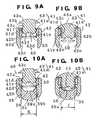
- FIG. 9A and 9Bare cross sections of the lens case taken along line 9 — 9 in FIG. 8A, wherein FIG. 9A shows a state in which the intraocular lens is located at a standby position, and FIG. 9B shows a state in which the press member of the lens is located at a insertion position;
- FIGS. 10A and 10Bare views showing the second embodiment, wherein FIG. 10A is a cross section taken along line 10 A— 10 A in FIG. 7A, and FIG. 10B is a cross section taken along line 10 B— 10 B in FIG. 7B;
- FIG. 11is a front view of an insertion device showing one modification of the second embodiment shown in FIGS. 7A and 7B in a state in which a lens case is separated from the insertion device;
- FIG. 12shows cross sections corresponding to those of FIGS. 10A and 10B and showing another modification of the second embodiment shown in FIGS. 7A and 7B, in which the lens case has a modified base portion;
- FIG. 13is a plan view showing a modified example of the insertion tube of the insertion device used in the second embodiment.
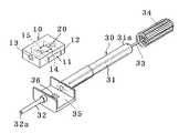
- FIG. 1is a perspective view showing the concept of an intraocular-lens insertion system according to the present invention.
- the system according to the present inventionis mainly composed of a lens case 10 , which serves as a lens package for storing an intraocular lens 20 , and an insertion device 30 for inserting the intraocular lens 20 into the eye of a patient.
- the lens case 10includes a lens case top 11 and a lens case bottom 12 , which are assembled so as to form a space 15 for storing the intraocular lens 20 .
- the lens case 10has a through hole 13 , which penetrates the lens case 10 in the longitudinal direction thereof and which serves as a portion of the mechanism to be provided by the insertion device 30 .
- An insertion tube 32is formed at the tip end of the insertion device 30 via an attachment portion 35 .
- the intraocular lens 20is inserted into the eye of the patient through the insertion tube 32 .
- a pusher mechanism 34is disposed at the rear end 31 a of a tubular main body 31 of the insertion device 30 .
- the pusher mechanism 34is coupled to the rear end of a push rod 33 for pushing the intraocular lens 20 into the eye.
- the lens case 10is formed to have a size that enables attachment of the lens case 10 to the attachment portion 35 of the insertion device 30 .
- the lens case 10is fixed onto the attachment portion 35 while being aligned therewith by means of a projection 14 projecting from the lens case top 11 of the lens case 10 and an engagement hole 36 formed in the attachment portion 35 .
- the push rod 33is advanced by means of the pusher mechanism 34 .
- the intraocular lens 20 stored in the lens case 10is pushed out from the tip end 32 a of the insertion tube 32 and inserted into the eye.
- the above-described structurerealizes the concept of the present invention such that when the lens case 10 serving as a lens package is attached to the insertion device 30 , the lens case 10 functions as a portion of the mechanism to be provided by the insertion device 30 .
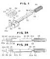
- FIGS. 2A and 2Bare views showing a first embodiment of the intraocular-lens insertion system according to the present invention, wherein FIG. 2A is a front view of the insertion device 30 to which the lens case 10 has been attached, and FIG. 2B is a bottom view of the insertion device 30 .
- the tubular main body 31 of the insertion device 30is formed of transparent or semi-transparent plastic such that the diameter at the base end 31 a is smaller than that at the tip end 31 b .
- the above-mentioned push shaft 33is disposed to be located on the center axis of the tubular main body 31 , and the through hole of the tapered insertion tube 32 is aligned with the center axis of the tubular main body 31 .
- the above-mentioned engagement hole 36is formed in the horizontal region of the attachment portion 35 , and a notch is formed on the rearward-facing surface of a front-side vertical wall of the attachment portion 35 .
- the engagement hole 36 and the notch 37cooperate to position the lens case 10 relative to the attachment portion 35 .
- the lens case 10is constituted through assembly of the lens case top 11 , on which is placed the intraocular lens 20 , and the lens case bottom 12 formed to cover the upper face of the intraocular lens 20 placed on the lens case top 11 .
- FIG. 3Ais a plan view of the lens case
- FIG. 3Bis a left side view of the lens case
- FIG. 3Cis a right side view of the lens case
- FIG. 3Dis a cross section taken along line 3 D— 3 D is FIG. 3A;
- a groove-shaped depression 11 ais formed on the upper surface of the lens case top 11 such that the depression 11 a extends in the horizontal direction in FIG. 3 A.
- Support portions 22 of the intraocular lens 20 for supporting the optical portion 21 of the intraocular lens 20are placed in the depression 11 a .
- the above-described projection 14 to be engaged with the engagement hole 36 of the attachment portion 35is formed on the lower surface of the lens case top 11 to be located at a position which is slightly offset rightward from the center in FIG. 3 A.
- the lens case bottom 12 for covering the upper surface of the lens case top 11is formed such that the lens case bottom 12 can be fitted onto the lens case top 11 while covering the upper surface and circumferential (side) surface of the lens case top 11 .
- the above-described through hole 13is formed in the left and right walls 12 a and 12 b such that the center of the through hole 13 is aligned with the center axis of the tubular main body 31 of the insertion device 30 when the lens case 10 is attached to the attachment portion 35 .
- the specific procedure for placement of the lens case 10is as follows. First, the intraocular lens 20 is placed on the lens case top 11 such that the optical portion 21 of the lens 20 corresponds to the depression 11 a of the lens case top 11 and such that the optical portion 21 and support portions 22 of the intraocular lens 20 are supported by the edge portions of the depression 11 a . Subsequently, the lens case bottom 12 is placed on the lens case top 11 , so that a space 15 is formed between the lens case bottom 12 and the lens case top 11 . The space 15 has a shape and size such that movement of the intraocular lens within the space 15 is restricted.
- the shape of the space 15is determined such that the optical portion 21 of the intraocular lens 20 does not come into contact with the inner surface of the lens case top 11 or the inner surface of the lens case bottom 12 , thereby preventing the optical characteristics of the optical portion 21 from changing due to force acting on the optical portion 21 during long-term storage.
- the through hole 13 of the lens case 10is reduced in diameter toward the tip end thereof.
- the intraocular lens 20 and the push rod 33pass through the through hole 13 .
- the push rod 33is advanced through operation of the pusher mechanism 34 .
- the intraocular lens 20 within the lens case 10is gradually deformed to a smaller size and is moved into the insertion tube 32 .
- the push rod 33is advanced further, so that the intraocular lens 20 is deformed to a further reduced size by means of the insertion tube 32 and is then pushed into the eye.
- the lens case 10provides a portion of the function of the insertion device 30 upon attachment to the insertion device 30 .
- FIGS. 3B and 3Dshow the diameter of the through hole 13 of the lens case 10 being gradually reduced toward the tip end thereof. That is, the transverse dimension C of the space 15 —which receives the intraocular lens 20 placed on the lens top case 11 of the lens case 10 as shown in FIG. 3 D—is reduced to a transverse dimension D which corresponds to that measured at the tip end of the through hole 13 as shown in FIG. 3 B.
- This configurationenables the intraocular lens 20 to enter a deformed state from a non-deformed state while being moved through the through hole 13 by means of the push rod 33 .
- the through hole 13has an asymmetrical shape with respect to the vertical direction. Further, a rail 16 projecting toward the center of the through hole 13 is formed such that the rail 16 extends in the direction of movement of the intraocular lens 20 . This configuration enables the intraocular lens 20 to be formed into an intended shape.
- FIG. 4is a front view showing a state in which the lens case 10 is separated from the insertion device 30 used in the first embodiment of the intraocular-lens insertion system according to the present invention.
- the notch 37is formed on a rearward-facing surface of the front-side vertical wall of the attachment portion 35 at a position corresponding to the height A of the lens case 10 .
- the notch function of the notch 37prevents unintentional separation of the attached lens case 10 from the attachment portion 35 .
- the projection 14 of the lens case 10 and the engagement hole 36 of the attachment portion 35are formed to have shapes and dimensions which enable establishment of fitting engagement therebetween, so that the relative position between them can be fixed. These mechanism enables the lens case 10 as shown in FIG. 2A to be attached to the insertion device 30 .
- FIG. 4shows an example in which the lens case 10 is attached to the insertion device 30 from above.
- the present inventionis not limited to such a style of attachment, and an alternative attachment method may be employed.
- the lens case 10 carrying the intraocular lens 20is placed on a desk or table in a state in which the projection 14 of the lens case top 11 faces upward; and the insertion device 30 is inverted and placed on the lens case 10 from above so as to cover it.
- FIG. 5is a view showing a modification of the first embodiment shown in FIGS. 2A and 2B.
- an engagement groove 38is provided in place of the engagement hole 36 provided on the attachment portion 35 .
- the engagement groove 38extends in a direction perpendicular to the push rod 33 .
- the lens case 10is attached to the insertion device 30 from the side thereof and is fixed by means of a notch 39 . Portions other than the above-mentioned portions are denoted by the same reference numerals as those used in FIG. 2, and their repeated descriptions are omitted.
- the attachment method employed in the above-described first embodimentcan be used. That is, the lens case 10 is placed on a desk or table; and the insertion device 30 is inverted and placed on the lens case 10 from above. This attachment method provides the same effect as that mentioned above.
- FIG. 6is a front view showing a modified example of the insertion tube 32 employed in the first embodiment.
- the insertion tube 32 shown in FIG. 6is formed to have a tapered through hole whose diameter gradually decreases toward the tip end thereof. Therefore, the intraocular lens 20 pushed into the base end 32 b of the insertion tube 32 by means of the push rod 33 can be deformed to a smaller size.
- the lens case 10serving as a lens package provides a portion of the function of the insertion device 30 upon attachment thereto.
- the lens case 10 and the insertion tube 32form deforming means for deforming the intraocular lens 20 .
- the present inventionis not limited thereto, and the configuration of the system may be modified to assume various configurations; e.g., a configuration such that only the lens case 10 is used to deform the intraocular lens 20 to a small size suitable for insertion into the eye, and the thus-deformed lens 20 is passed through the insertion tube 32 and inserted into the eye; and a configuration such that deforming means is not provided on the lens case 10 , but is provided on the insertion tube 32 .
- the intraocular lens 20has plate-shaped support portions 22 extending from the opposite ends of the optical portion 21 .
- center of the intraocular lens 20refers to the center in the thickness direction located on the optical axis of the optical portion 21 .
- an intraocular lens 50 horizontally stored in a lens case 40 serving as a lens packageis moved between a first or standby position at which the vertical position of the center of the intraocular lens 50 does not coincide with the center axis of the push rod 33 of the insertion device 30 , and a second or insertion position at which the vertical position of the center of the intraocular lens 50 coincides with the center axis of the push rod 33 of the insertion device 30 , so that the intraocular lens 50 can be pushed out by the push rod 33 .
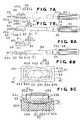
- FIG. 7Ais a front view of the insertion device 30 to which the lens case 40 has been attached and in which the intraocular lens 50 is located at the first or standby position
- FIG. 7Bis a front view of the insertion device 30 in which the intraocular lens 50 is located at the second or insertion position.
- the vertical position of the center of the lensdoes not coincide with the center axis of the push rod 33 represented by an alternate long and short dash line L.
- the intraocular lens 50is moved downward to the second or insertion position shown in FIG. 7B, at which the vertical position of the center of the lens substantially coincides with the center axis of the push rod 33 .
- the intraocular lens 50can be pushed out from the tip end 32 a of the insertion tube 32 into the eye through advancing movement of the push rod 33 effected by the pusher mechanism 34 provided at the rear end 31 a of the tubular main body 31 .
- FIGS. 8A to 8 Care views showing a state in which the lens case 40 is separated from the insertion device 30 .
- FIG. 8Ais a front view of the insertion device 30
- FIG. 8Bis an enlarged plane view of the lens case 40
- FIG. 8Cis a cross section taken along line 8 C— 8 C in FIG. 8 B.
- the attachment portion 35is attached in advance to the insertion device 30 shown in FIG. 8 A.
- the lens case 40consists of a lens case top 41 and a lens case base 42 having a structure suitable for supporting the intraocular lens 50 having loop-shaped support portions 52 made of a material different from that of the optical portion 51 .
- the lens case base 42has engagement portions 42 b which have inclined surfaces 42 a of angle ⁇ extending in opposite longitudinal directions in order to maintain the angle ⁇ between the optical portion 51 and the support portions 52 of the intraocular lens 50 .
- the lens case top 41has on its bottom surface 41 b inclined surfaces to be mated with the inclined surfaces 42 a of the lens case base 42 . After placement of the lens 50 on the lens case base 42 , the lens case top 41 is placed on the lens case base 42 , so that the support portions 52 of the lens 50 are sandwiched between the lens case base 42 and the lens case top 41 .
- the lens case top 41is provided with the push member 43 .
- the lens case base 42has an opening 42 c in the top surface thereof and projections 42 e in the vicinity of the lower ends of opposite side walls 42 d .
- the projections 42 eelastically engage with engagement steps 38 formed in the vicinity of the lower ends of the lateral side surfaces of the attachment portion 35 .
- the longitudinal opposite ends of the lens case base 42are opened, giving the lens case base 42 a squarish C-like cross section.
- the paired engagement portions 42 bare formed on the inner surfaces of the side walls 42 d to be located at the approximate center in the vertical direction.
- the engagement portions 42 bextend in the longitudinal direction and are adapted to receive the peripheral portions of the optical portion 51 and the support portions 52 of the intraocular lens 50 .
- the inclined surfaces 42 a each having an inclination angle ⁇are formed on the engagement portions 42 b in order to maintain the angle ⁇ between the optical portion 51 and the support portions 52 of the intraocular lens 50 .
- the lens case top 41 to be inserted into the top surface opening 42 c of the lens case base 42has a hollow nipping member 41 a having a rectangular frame-like shape, and the above-mentioned push member 43 is disposed in the nipping member 41 a to be movable in the vertical direction.
- the bottom surface 41 b of the nipping member 41 ahas inclined portions to come into contact with the inclined surfaces 42 a of the engagement portions 42 b of the lens case base 42 .
- Upper and lower depressions 41 d and 41 eare formed at a predetermined interval on each of the inner surfaces 41 c of the opposite lateral walls such that the upper depressions 41 d are opposed to each other and the lower depressions 41 e are opposed to each other.
- the above-mentioned push member 43is inserted into the opening 41 f of the nipping member 41 a and is pressed downward in order to move the intraocular lens 50 from the standby position to the insertion position.
- the push member 43has a head portion 43 a of large diameter and a prism-shaped leg portion 43 b .
- Protrusions 43 care formed on the peripheral surface thereof and in the vicinity of the lower end thereof so as to be engaged selectively with the upper depressions 41 d or the lower depressions 41 e of the nipping member 41 a .
- the protrusions 43 c of the push member 43engage the depressions 41 d , and when the push member 43 is pressed, the protrusions 43 c move downward and come into engagement with the depressions 41 e .
- a concave surface 43 dis formed on the bottom surface of the leg portion 43 a , and a ridge 43 f for supporting the peripheral portion of the intraocular lens 50 is formed on the concave surface 43 d.
- the head portion 43 a of the push member 43 of the lens top 41is pressed down such that the intraocular lens 50 —which is nipped by the lens case base 42 and the lens case top 41 of the lens case 40 is moved to a lens movement portion 39 of the attachment portion 35 .
- the lens movement portion 39has a shape of a concavely-curved groove.
- the vertical position of the center of the lens 50substantially coincides with the center axis of the push rod 33 .
- the intraocular lens 50is moved within the space 15 of the lens movement portion 39 in the direction perpendicular to the page of FIG. 10B, passed through the insertion tube 32 provided integrally with the attachment portion 35 , and then pushed into the eye. Since upon pressing of the push member 43 the protrusions 43 c come into engagement with the depressions 41 e , the intraocular lens 50 having been moved to the lens movement portion 39 is prevented from reassuming its original shape, and reliable positioning is effected.
- the lens case 40is preferably transparent or semi-transparent, which allows an operator to check whether the lens 50 has been moved to the lens movement portion 39 .
- the push member 43 of the lens case top 41provides two functions; i.e., the function for moving the lens 50 downward and the function for forming the lens movement space 15 in cooperation with the attachment portion 35 .
- the lens case 40 of the second embodimentwhich consists of the lens case base 42 and the lens case top 41 including the nipping member 41 a and the push member 43 —provides a portion of the mechanism of the insertion device 30 upon attachment thereto.
- the present embodimentis characterized in that a portion of deforming means for deforming the intraocular lens 50 to a reduced size is formed integrally with the lens case 40 .
- the lens movement portion 39 of the attachment portion 35when the lens is moved to the lens movement portion 39 of the attachment portion 35 , the lens is deformed to a reduced size.
- This size reductionis achieved by three design features; i.e., the lens movement portion 39 being formed into a form of a curved groove, the lens 50 being moved while been pressed toward the lens movement portion 39 by the lens case top 41 , and the dimension J of the lens movement portion 39 being smaller than the dimension K of the lens 50 .
- FIG. 11is a front view of an insertion device showing one modification of the second embodiment shown in FIGS. 7A and 7B in a state in which the lens case 40 is separated from the insertion device 30 .
- the lens case 40is attached to the insertion device in a manner different from that described with reference to FIGS. 7A and 7B in which the lens case 40 is attached to the attachment portion 35 of the insertion device 30 from above. That is, after the lens case 40 in an inverted state is placed on a lens case support 60 , the insertion device 30 is inverted, and the attachment portion 35 of the insertion device 30 is elastically fitted onto the lens case base 42 of the lens case 40 .
- the remaining structureis the same as that of the above-described second embodiment.
- attachment of the lens case 40is preferably performed in a method in which an operator places the lens case 40 on a support, holds in his hand the insertion device 30 , which is larger and easier to hold than the lens case 40 , and fits it onto the lens case 40 from above.
- FIG. 12shows cross sections corresponding to those of FIGS. 10A and 10B and showing another modification of the second embodiment shown in FIGS. 7A and 7B, in which the lens case has a modified base portion.
- a lens case base 72 of a lens case 70 according to the present modificationhas an opening 72 a on the top surface, and also has an engagement groove 72 c in one of opposite side walls 72 b .
- the engagement groove 72 cpenetrates the corresponding side wall 72 b in a direction perpendicular to the lens insertion direction, and the attachment portion 35 is inserted into the lens case base 72 through the engagement groove 72 c .
- the lens case 70may be easily attached to the insertion device 30 by a different method in which an operator places the lens case 70 on a table, holds in his hand the insertion device 30 , and fits the attachment portion 35 into the lens case 70 through the engagement groove 72 c.
- attachment of the lens case 70is preferably performed in a method in which an operator places the lens case 70 on a support, holds in his hand the insertion device 30 , which is larger and easier to hold than the lens case 70 , and fits it onto the lens case 70 from one side thereof.
- the remaining structureis the same as that of the above-described second embodiment.
- the push member 73 of the lens case top 71is depressed to thereby move the intraocular lens 50 into the lens movement portion 39 of the attachment portion 35 , and the intraocular lens 50 is then inserted into the eye from the tip end of the insertion tube through advancement of the push rod 33 .
- FIG. 13is a plan view showing a modified example of the insertion tube 32 of the insertion device 30 used in the second embodiment.
- the insertion tube 32is formed integrally with the attachment portion 35 of the insertion device 30 , such that a groove-shaped curved depression 39 a serving as a lens deforming means is formed on the base end side of the insertion tube 32 .
Landscapes
- Health & Medical Sciences (AREA)
- Ophthalmology & Optometry (AREA)
- Cardiology (AREA)
- Oral & Maxillofacial Surgery (AREA)
- Transplantation (AREA)
- Engineering & Computer Science (AREA)
- Biomedical Technology (AREA)
- Heart & Thoracic Surgery (AREA)
- Vascular Medicine (AREA)
- Life Sciences & Earth Sciences (AREA)
- Animal Behavior & Ethology (AREA)
- General Health & Medical Sciences (AREA)
- Public Health (AREA)
- Veterinary Medicine (AREA)
- Prostheses (AREA)
Abstract
Description
Claims (31)
Priority Applications (3)
| Application Number | Priority Date | Filing Date | Title |
|---|---|---|---|
| JP28439399AJP3728155B2 (en) | 1999-10-05 | 1999-10-05 | Intraocular lens insertion system |
| US09/745,123US6468282B2 (en) | 1999-10-05 | 2000-12-20 | Insertion system for intraocular lens |
| US10/972,114USRE40185E1 (en) | 1999-10-05 | 2004-10-22 | Insertion system for intraocular lens |
Applications Claiming Priority (2)
| Application Number | Priority Date | Filing Date | Title |
|---|---|---|---|
| JP28439399AJP3728155B2 (en) | 1999-10-05 | 1999-10-05 | Intraocular lens insertion system |
| US09/745,123US6468282B2 (en) | 1999-10-05 | 2000-12-20 | Insertion system for intraocular lens |
Related Child Applications (1)
| Application Number | Title | Priority Date | Filing Date |
|---|---|---|---|
| US10/972,114ReissueUSRE40185E1 (en) | 1999-10-05 | 2004-10-22 | Insertion system for intraocular lens |
Publications (2)
| Publication Number | Publication Date |
|---|---|
| US20020077633A1 US20020077633A1 (en) | 2002-06-20 |
| US6468282B2true US6468282B2 (en) | 2002-10-22 |
Family
ID=26555452
Family Applications (2)
| Application Number | Title | Priority Date | Filing Date |
|---|---|---|---|
| US09/745,123CeasedUS6468282B2 (en) | 1999-10-05 | 2000-12-20 | Insertion system for intraocular lens |
| US10/972,114Expired - LifetimeUSRE40185E1 (en) | 1999-10-05 | 2004-10-22 | Insertion system for intraocular lens |
Family Applications After (1)
| Application Number | Title | Priority Date | Filing Date |
|---|---|---|---|
| US10/972,114Expired - LifetimeUSRE40185E1 (en) | 1999-10-05 | 2004-10-22 | Insertion system for intraocular lens |
Country Status (2)
| Country | Link |
|---|---|
| US (2) | US6468282B2 (en) |
| JP (1) | JP3728155B2 (en) |
Cited By (81)
| Publication number | Priority date | Publication date | Assignee | Title |
|---|---|---|---|---|
| US20020173847A1 (en)* | 2001-01-25 | 2002-11-21 | Hai-Minh Pham | Method of manufacturing an intraocular lens system |
| US20030074060A1 (en)* | 2001-01-25 | 2003-04-17 | Gholam-Reza Zadno-Azizi | Method of preparing an intraocular lens for implantation |
| EP1360947A1 (en)* | 2002-05-08 | 2003-11-12 | Canon-Staar Co., Inc. | Insertion System for Intraocular Lens |
| US20030212406A1 (en)* | 2002-05-08 | 2003-11-13 | Kenichi Kobayashi | Insertion device for intraocular lens |
| US6666871B2 (en)* | 2002-01-23 | 2003-12-23 | Canon-Staar Co. Inc. | Insertion device for deformable intraocular lens |
| US20040199173A1 (en)* | 2003-04-07 | 2004-10-07 | Anton Meyer & Co. Ag | Cartridge for an intraocular lens |
| US20040238392A1 (en)* | 2003-06-02 | 2004-12-02 | Peterson Rod T. | Intraocular lens and cartridge packaging with lens-loading function |
| US20040243141A1 (en)* | 2003-05-28 | 2004-12-02 | Kyle Brown | Lens delivery system |
| US20050049605A1 (en)* | 2003-08-28 | 2005-03-03 | Edward Vaquero | Preloaded IOL injector |
| US20050049606A1 (en)* | 2003-08-28 | 2005-03-03 | Edward Vaquero | Preloaded IOL injector |
| US20050149056A1 (en)* | 2003-12-22 | 2005-07-07 | Rathert Brian D. | IOL injector device and method |
| US20050216080A1 (en)* | 2000-03-08 | 2005-09-29 | Snyder Michael E | Intraocular lens with improved haptic and method of implanting same |
| US20060085013A1 (en)* | 2004-10-20 | 2006-04-20 | Vaclav Dusek | Intraocular lens inserter |
| US20060142780A1 (en)* | 2004-12-29 | 2006-06-29 | Joel Pynson | Preloaded IOL injector and method |
| US20060142781A1 (en)* | 2004-12-29 | 2006-06-29 | Joel Pynson | Preloaded IOL injector and method |
| US20060167466A1 (en)* | 2005-01-21 | 2006-07-27 | Vaclav Dusek | Intraocular lens inserter system components |
| US20060184181A1 (en)* | 2005-02-11 | 2006-08-17 | Cole Mark S | Front loading IOL insertion apparatus and method of using |
| US20070060925A1 (en)* | 2003-09-26 | 2007-03-15 | Joel Pynson | Preloaded iol injector and method |
| US20080033449A1 (en)* | 2005-02-11 | 2008-02-07 | Advanced Medical Optics, Inc. | Intraocular lens insertion apparatus and lens case |
| US20080045971A1 (en)* | 2003-02-14 | 2008-02-21 | Ian Ayton | Method and Device for Compacting an Intraocular Lens |
| US20080058830A1 (en)* | 2005-02-11 | 2008-03-06 | Advanced Medical Optics, Inc. | Rapid exchange iol insertion apparatus and methods of using |
| US20080097460A1 (en)* | 2006-10-23 | 2008-04-24 | Alcon Manufacturing, Ltd. | Intraocular lens delivery system with temperature control |
| US20080097461A1 (en)* | 2006-10-23 | 2008-04-24 | Alcon Manufacturing, Ltd. | Method of delivering temperature controlled intraocular lens |
| US20080147081A1 (en)* | 2006-12-13 | 2008-06-19 | Joel Pynson | Intraocular lens injector apparatus and methods of use |
| US20080147082A1 (en)* | 2006-12-13 | 2008-06-19 | Joel Pynson | Injector apparatus for use with intraocular lenses and methods of use |
| US20080243139A1 (en)* | 2007-03-15 | 2008-10-02 | Vaclav Dusek | Method for assembling a ring used in a small pupil phaco procedure |
| US20090204123A1 (en)* | 2008-02-07 | 2009-08-13 | David Downer | Lens Delivery System Cartridge |
| US7645300B2 (en) | 2004-02-02 | 2010-01-12 | Visiogen, Inc. | Injector for intraocular lens system |
| US20100160926A1 (en)* | 2008-12-18 | 2010-06-24 | Alex Artsyukhovich | Constant force intraocular lens injector |
| EP2286762A1 (en) | 2009-08-18 | 2011-02-23 | Carl Zeiss Meditec SAS | Holding device for an intraocular lens, packaging and transport means for an intraocular lens, injector device for an intraocular lens as well as method for packaging an intraocular lens and method for loading an intraocular lens into an injector device |
| US20110046635A1 (en)* | 2009-08-18 | 2011-02-24 | Dmitry Pankin | Cassette For Receiving An Intraocular Lens, Injector Device And Method For Advancing An Intraocular Lens Out Of A Cassette |
| US20110046633A1 (en)* | 2009-08-18 | 2011-02-24 | Dmitry Pankin | Cassette For An Intraocular Lens, Injector Device With Such A Cassette, Method For Storing An Intraocular Lens In A Cassette and Method For Advancing An Intraocular Lens Out Of A Cassette |
| US7901414B2 (en) | 2001-12-12 | 2011-03-08 | Ioltechnologie-Production | Cassette and injector for flexible intraocular lens and method for injecting such lenses |
| US20110137321A1 (en)* | 2005-12-22 | 2011-06-09 | Joel Pynson | Apparatus and methods for loading of an iol injector |
| US20110144653A1 (en)* | 2009-11-20 | 2011-06-16 | Dmitry Pankin | Injector Tip For An Injector Device As Well As Injector Device For Introducing An Intraocular Lens Into An Eye As Well As Method For Transporting An Intraocular Lens In An Injector Tip |
| US8187325B2 (en) | 2001-01-25 | 2012-05-29 | Visiogen, Inc. | Materials for use in accommodating intraocular lens system |
| US20120158007A1 (en)* | 2010-12-20 | 2012-06-21 | Kyle Brown | Intraocular lens transfer case |
| US8273122B2 (en) | 2008-06-23 | 2012-09-25 | Abbott Medical Optics Inc. | Pre-loaded IOL insertion system |
| US8377123B2 (en) | 2004-11-10 | 2013-02-19 | Visiogen, Inc. | Method of implanting an intraocular lens |
| US8382769B2 (en) | 2008-06-17 | 2013-02-26 | Hoya Corporation | Intraocular lens insertion device |
| US8403984B2 (en) | 2006-11-29 | 2013-03-26 | Visiogen, Inc. | Apparatus and methods for compacting an intraocular lens |
| US8425595B2 (en) | 2008-03-12 | 2013-04-23 | Visiogen, Inc. | Method for inserting an intraocular lens |
| US8460311B2 (en) | 2004-12-27 | 2013-06-11 | Hoya Corporation | Intraocular lens implanting device |
| US8470032B2 (en) | 2008-09-04 | 2013-06-25 | Hoya Corporation | Intraocular lens insertion device |
| US8475528B2 (en) | 2007-05-30 | 2013-07-02 | Hoya Corporation | Intraocular lens insertion device |
| US8523941B2 (en) | 2005-12-08 | 2013-09-03 | Hoya Corporation | Instrument for inserting intraocular lens |
| US8523877B2 (en) | 2005-02-24 | 2013-09-03 | Hoya Corporation | Intraocular lens inserting instrument |
| US8545512B2 (en)* | 2005-01-26 | 2013-10-01 | Hoya Corporation | Intraocular lens insertion device |
| US8574239B2 (en) | 2005-09-28 | 2013-11-05 | Hoya Corporation | Intraocular lens insertion device |
| US8579969B2 (en) | 2010-07-25 | 2013-11-12 | Alcon Research, Ltd. | Dual mode automated intraocular lens injector device |
| US8603103B2 (en) | 2009-01-07 | 2013-12-10 | Hoya Corporation | Intraocular lens insertion device |
| US8647382B2 (en) | 2010-06-10 | 2014-02-11 | Hoya Corporation | Ocular implant insertion apparatus and methods |
| US8668734B2 (en) | 2010-07-09 | 2014-03-11 | Powervision, Inc. | Intraocular lens delivery devices and methods of use |
| US8702795B2 (en) | 2008-08-21 | 2014-04-22 | Hoya Corporation | Intraocular lens inserting device |
| US8747465B2 (en) | 2007-05-30 | 2014-06-10 | Hoya Corporation | Intraocular lens insertion device |
| US8956408B2 (en) | 2007-07-23 | 2015-02-17 | Powervision, Inc. | Lens delivery system |
| US8968396B2 (en) | 2007-07-23 | 2015-03-03 | Powervision, Inc. | Intraocular lens delivery systems and methods of use |
| US8998983B2 (en) | 2012-06-04 | 2015-04-07 | Altaviz, Llc | Intraocular lens inserters |
| US9114006B2 (en) | 2007-07-11 | 2015-08-25 | Hoya Corporation | Intraocular lens insertion device and method for controlling movement of the intraocular lens |
| US20150342730A1 (en)* | 2012-12-20 | 2015-12-03 | Humanoptics Ag | Intraocular lens storage system |
| US9326847B2 (en) | 2010-04-08 | 2016-05-03 | Hoya Corporation | Ocular implant insertion apparatus and methods |
| US9463089B2 (en) | 2012-05-21 | 2016-10-11 | Novartis Ag | Plunger system for intraocular lens surgery |
| US9549813B2 (en) | 2010-08-24 | 2017-01-24 | Abbott Medical Optics Inc. | Inserter cap and related features |
| US9554894B2 (en) | 2008-06-05 | 2017-01-31 | Hoya Corporation | Intraocular lens insertion device and cartridge |
| US9610155B2 (en) | 2008-07-23 | 2017-04-04 | Powervision, Inc. | Intraocular lens loading systems and methods of use |
| USD789520S1 (en) | 2015-02-18 | 2017-06-13 | Icares Medicus, Inc. | Injector barrel and plunger |
| US9693895B2 (en) | 2012-06-12 | 2017-07-04 | Altaviz, Llc | Intraocular gas injector |
| US10010408B2 (en) | 2014-04-04 | 2018-07-03 | Alcon Pharmaceuticals, Ltd. | Intraocular lens inserter |
| US10172706B2 (en) | 2015-10-31 | 2019-01-08 | Novartis Ag | Intraocular lens inserter |
| US10195020B2 (en) | 2013-03-15 | 2019-02-05 | Powervision, Inc. | Intraocular lens storage and loading devices and methods of use |
| US10568735B2 (en) | 2017-01-13 | 2020-02-25 | Alcon Inc. | Intraocular lens injector |
| US10588780B2 (en) | 2015-03-04 | 2020-03-17 | Alcon Inc. | Intraocular lens injector |
| US10773478B1 (en)* | 2019-07-16 | 2020-09-15 | Triple Win Technology (Shenzhen) Co. Ltd. | Testing device |
| US10799339B2 (en) | 2015-09-16 | 2020-10-13 | Hoya Corporation | Intraocular lens injector |
| US10849738B2 (en) | 2015-09-16 | 2020-12-01 | Hoya Corporation | Intraocular lens injector |
| US11000367B2 (en) | 2017-01-13 | 2021-05-11 | Alcon Inc. | Intraocular lens injector |
| US11033382B2 (en) | 2016-06-28 | 2021-06-15 | Hoya Corporation | Intraocular lens injector |
| US11224537B2 (en) | 2018-10-19 | 2022-01-18 | Alcon Inc. | Intraocular gas injector |
| US12076231B2 (en) | 2018-05-25 | 2024-09-03 | Hoya Corporation | Intraocular lens injector |
| US12257145B2 (en) | 2018-05-16 | 2025-03-25 | HOYA Medical Singapore Pte. Ltd. | Intraocular lens injector with container |
| US12414852B2 (en) | 2016-06-28 | 2025-09-16 | HOYA Medical Singapore Pte. Ltd. | Intraocular lens injector |
Families Citing this family (19)
| Publication number | Priority date | Publication date | Assignee | Title |
|---|---|---|---|---|
| CA2849167C (en)* | 2002-07-25 | 2016-06-28 | Visiogen, Inc. | Intraocular lenses and methods of preparing or making same |
| JP4080394B2 (en)* | 2003-07-31 | 2008-04-23 | 株式会社ニデック | Intraocular lens insertion device |
| US20070185499A1 (en)* | 2004-02-27 | 2007-08-09 | Advanced Vision Science, Inc. | Device for the insertion of deformable intra-ocular lenses |
| DE502004009370D1 (en)* | 2004-02-27 | 2009-05-28 | Advanced Vision Science Inc | LENS RECEPTION FOR A DEVICE FOR INSERTING DEFORMABLE INTRAOCULAR LENSES |
| JP4520256B2 (en)* | 2004-09-06 | 2010-08-04 | 株式会社ニデック | Intraocular lens insertion device |
| JP4520255B2 (en)* | 2004-09-06 | 2010-08-04 | 株式会社ニデック | Intraocular lens insertion device |
| JP4766442B2 (en)* | 2004-12-28 | 2011-09-07 | Hoya株式会社 | Intraocular lens insertion device |
| US8475526B2 (en)* | 2005-12-22 | 2013-07-02 | Bausch & Lomb Incorporated | Apparatus and methods for loading of an IOL injector |
| US8435288B2 (en)* | 2006-09-22 | 2013-05-07 | Lenstec Barbados Inc. | System and method for storing, shipping and injecting ocular devices |
| US8518110B2 (en)* | 2006-09-22 | 2013-08-27 | Lenstec Barbados Inc. | System and method for storing, shipping and injecting ocular devices |
| US9149619B2 (en) | 2006-09-22 | 2015-10-06 | Lenstec Barbados Inc. | System and method for storing, shipping and injecting ocular devices |
| US20080147080A1 (en)* | 2006-12-13 | 2008-06-19 | Joel Pynson | Injector apparatus for use with intraocular lenses and methods of use |
| CH699588A1 (en)* | 2008-09-22 | 2010-03-31 | Medicel Ag | Cartridge for an intraocular lens injector system and for it. |
| JP5301942B2 (en)* | 2008-10-17 | 2013-09-25 | 株式会社ニデック | Intraocular lens insertion device |
| NL2005182C2 (en) | 2010-07-30 | 2012-01-31 | Oculentis B V | Intraocular lens injector system. |
| US9931242B2 (en) | 2012-09-07 | 2018-04-03 | Bausch & Lomb Incorporated | Intraocular lens injector assembly including a shuttle and method of using same |
| JP5545606B2 (en)* | 2013-04-18 | 2014-07-09 | Hoya株式会社 | Intraocular lens insertion device and cartridge |
| US20210059811A1 (en)* | 2017-12-28 | 2021-03-04 | Medicontur Medical Engineering Ltd. | Injector system for intraocular lenses |
| CN119908875A (en)* | 2024-12-26 | 2025-05-02 | 河南宇宙人工晶状体研制有限公司 | Hydrophilic preloaded intraocular lens injector |
Citations (13)
| Publication number | Priority date | Publication date | Assignee | Title |
|---|---|---|---|---|
| JPS58146346A (en) | 1982-02-05 | 1983-08-31 | トマス・ア−ル・マゾツコ | Deformable intraocular lens and method and apparatus for implanting same |
| US4681102A (en) | 1985-09-11 | 1987-07-21 | Bartell Michael T | Apparatus and method for insertion of an intra-ocular lens |
| US5098439A (en) | 1989-04-12 | 1992-03-24 | Allergan, Inc. | Small incision intraocular lens insertion apparatus |
| US5190552A (en) | 1992-02-04 | 1993-03-02 | Kelman Charles D | Slotted tube injector for an intraocular lens |
| JPH05103803A (en) | 1991-06-13 | 1993-04-27 | Canon Star Kk | Transplantation device of intraocular lens |
| US5275604A (en)* | 1992-12-03 | 1994-01-04 | Kabi Pharmacia Ophthalmics, Inc. | Contoured duct apparatus and method for insertion of flexible intraocular lens |
| JPH0723991A (en) | 1993-07-15 | 1995-01-27 | Canon Star Kk | Instrument for inserting deformable intraocular implant |
| US5474562A (en)* | 1993-03-09 | 1995-12-12 | Chiron Vision Corporation | Apparatus and method for preparing an intraocular lens for insertion |
| US5496328A (en) | 1993-07-15 | 1996-03-05 | Canon Staar Co., Inc. | Inserting device for deformable intraocular lens |
| JPH09506285A (en) | 1994-08-05 | 1997-06-24 | カイロン ビジョン コーポレイション | Device for inserting a flexible intraocular lens |
| US5643275A (en)* | 1993-07-02 | 1997-07-01 | Pharmacia Iovision, Inc. | Intraocular lens injector |
| US5807400A (en)* | 1992-09-30 | 1998-09-15 | Staar Surgical Company, Inc. | Deformable intraocular lens insertion system |
| US5860984A (en)* | 1992-09-30 | 1999-01-19 | Staar Surgical Company, Inc. | Spring biased deformable intraocular injecting apparatus |
Family Cites Families (1)
| Publication number | Priority date | Publication date | Assignee | Title |
|---|---|---|---|---|
| US5947975A (en)* | 1997-03-07 | 1999-09-07 | Canon Staar Co., Inc. | Inserting device for deformable intraocular lens |
- 1999
- 1999-10-05JPJP28439399Apatent/JP3728155B2/ennot_activeExpired - Lifetime
- 2000
- 2000-12-20USUS09/745,123patent/US6468282B2/ennot_activeCeased
- 2004
- 2004-10-22USUS10/972,114patent/USRE40185E1/ennot_activeExpired - Lifetime
Patent Citations (14)
| Publication number | Priority date | Publication date | Assignee | Title |
|---|---|---|---|---|
| JPS58146346A (en) | 1982-02-05 | 1983-08-31 | トマス・ア−ル・マゾツコ | Deformable intraocular lens and method and apparatus for implanting same |
| US4681102A (en) | 1985-09-11 | 1987-07-21 | Bartell Michael T | Apparatus and method for insertion of an intra-ocular lens |
| US5098439A (en) | 1989-04-12 | 1992-03-24 | Allergan, Inc. | Small incision intraocular lens insertion apparatus |
| JPH05103803A (en) | 1991-06-13 | 1993-04-27 | Canon Star Kk | Transplantation device of intraocular lens |
| US5190552A (en) | 1992-02-04 | 1993-03-02 | Kelman Charles D | Slotted tube injector for an intraocular lens |
| US5860984A (en)* | 1992-09-30 | 1999-01-19 | Staar Surgical Company, Inc. | Spring biased deformable intraocular injecting apparatus |
| US5807400A (en)* | 1992-09-30 | 1998-09-15 | Staar Surgical Company, Inc. | Deformable intraocular lens insertion system |
| US5275604A (en)* | 1992-12-03 | 1994-01-04 | Kabi Pharmacia Ophthalmics, Inc. | Contoured duct apparatus and method for insertion of flexible intraocular lens |
| US5474562A (en)* | 1993-03-09 | 1995-12-12 | Chiron Vision Corporation | Apparatus and method for preparing an intraocular lens for insertion |
| US5643275A (en)* | 1993-07-02 | 1997-07-01 | Pharmacia Iovision, Inc. | Intraocular lens injector |
| JPH0723991A (en) | 1993-07-15 | 1995-01-27 | Canon Star Kk | Instrument for inserting deformable intraocular implant |
| US5496328A (en) | 1993-07-15 | 1996-03-05 | Canon Staar Co., Inc. | Inserting device for deformable intraocular lens |
| JPH09506285A (en) | 1994-08-05 | 1997-06-24 | カイロン ビジョン コーポレイション | Device for inserting a flexible intraocular lens |
| US5873879A (en)* | 1994-08-05 | 1999-02-23 | Chiron Vision Corporation | Device for inserting a flexible intraocular lens |
Cited By (159)
| Publication number | Priority date | Publication date | Assignee | Title |
|---|---|---|---|---|
| US20050216080A1 (en)* | 2000-03-08 | 2005-09-29 | Snyder Michael E | Intraocular lens with improved haptic and method of implanting same |
| US6899732B2 (en) | 2001-01-25 | 2005-05-31 | Visiogen, Inc. | Method of implanting an intraocular lens system |
| US20030074060A1 (en)* | 2001-01-25 | 2003-04-17 | Gholam-Reza Zadno-Azizi | Method of preparing an intraocular lens for implantation |
| US7452362B2 (en) | 2001-01-25 | 2008-11-18 | Visiogen, Inc. | Method of implanting an intraocular lens system |
| US20020173847A1 (en)* | 2001-01-25 | 2002-11-21 | Hai-Minh Pham | Method of manufacturing an intraocular lens system |
| US8187325B2 (en) | 2001-01-25 | 2012-05-29 | Visiogen, Inc. | Materials for use in accommodating intraocular lens system |
| US20050165410A1 (en)* | 2001-01-25 | 2005-07-28 | Gholam-Reza Zadno-Azizi | Method of implanting an intraocular lens system |
| US7744646B2 (en) | 2001-01-25 | 2010-06-29 | Visiogen, Inc. | Method of preparing an intraocular lens for implantation |
| US7744603B2 (en) | 2001-01-25 | 2010-06-29 | Visiogen, Inc. | Method of implanting an intraocular lens system |
| US6884261B2 (en) | 2001-01-25 | 2005-04-26 | Visiogen, Inc. | Method of preparing an intraocular lens for implantation |
| US7901414B2 (en) | 2001-12-12 | 2011-03-08 | Ioltechnologie-Production | Cassette and injector for flexible intraocular lens and method for injecting such lenses |
| US6666871B2 (en)* | 2002-01-23 | 2003-12-23 | Canon-Staar Co. Inc. | Insertion device for deformable intraocular lens |
| US20030212406A1 (en)* | 2002-05-08 | 2003-11-13 | Kenichi Kobayashi | Insertion device for intraocular lens |
| US7014641B2 (en)* | 2002-05-08 | 2006-03-21 | Canon-Staar Co., Inc. | Insertion device for intraocular lens |
| EP1360947A1 (en)* | 2002-05-08 | 2003-11-12 | Canon-Staar Co., Inc. | Insertion System for Intraocular Lens |
| US7615056B2 (en) | 2003-02-14 | 2009-11-10 | Visiogen, Inc. | Method and device for compacting an intraocular lens |
| US20080045971A1 (en)* | 2003-02-14 | 2008-02-21 | Ian Ayton | Method and Device for Compacting an Intraocular Lens |
| US9095426B2 (en)* | 2003-02-14 | 2015-08-04 | Visiogen, Inc. | Method and device for compacting an intraocular lens |
| US20040199173A1 (en)* | 2003-04-07 | 2004-10-07 | Anton Meyer & Co. Ag | Cartridge for an intraocular lens |
| US7476229B2 (en) | 2003-04-07 | 2009-01-13 | Anton Meyer & Co. Ag | Cartridge for an intraocular lens |
| US20040243141A1 (en)* | 2003-05-28 | 2004-12-02 | Kyle Brown | Lens delivery system |
| US7156854B2 (en) | 2003-05-28 | 2007-01-02 | Alcon, Inc. | Lens delivery system |
| US20070123980A1 (en)* | 2003-06-02 | 2007-05-31 | Advanced Medical Optics, Inc. | Intraocular lens and cartridge packaging with lens-loading function |
| US8475527B2 (en) | 2003-06-02 | 2013-07-02 | Abbott Medical Optics Inc. | Intraocular lens and cartridge packaging with lens-loading function |
| US20040238392A1 (en)* | 2003-06-02 | 2004-12-02 | Peterson Rod T. | Intraocular lens and cartridge packaging with lens-loading function |
| US8403941B2 (en) | 2003-06-02 | 2013-03-26 | Abbott Medical Optics Inc. | Intraocular lens and cartridge packaging with lens-loading function |
| US9907648B2 (en) | 2003-06-02 | 2018-03-06 | Abbott Medical Optics Inc. | Intraocular lens and cartridge packaging with lens-loading function |
| US20050049606A1 (en)* | 2003-08-28 | 2005-03-03 | Edward Vaquero | Preloaded IOL injector |
| US9277989B2 (en) | 2003-08-28 | 2016-03-08 | Bausch & Lomb Incorporated | Preloaded IOL injector |
| US7988701B2 (en)* | 2003-08-28 | 2011-08-02 | Bausch & Lomb Incorporated | Preloaded IOL injector |
| US20050222579A1 (en)* | 2003-08-28 | 2005-10-06 | Edward Vaquero | Preloaded IOL injector |
| US20050049605A1 (en)* | 2003-08-28 | 2005-03-03 | Edward Vaquero | Preloaded IOL injector |
| US7422604B2 (en)* | 2003-08-28 | 2008-09-09 | Bausch & Lomb Incorporated | Preloaded IOL injector |
| US7429263B2 (en) | 2003-08-28 | 2008-09-30 | Bausch & Lomb Incorporated | Preloaded IOL injector |
| EP1659991B2 (en)† | 2003-08-28 | 2013-07-17 | Bausch & Lomb Incorporated | Preloaded iol injector |
| US20070060925A1 (en)* | 2003-09-26 | 2007-03-15 | Joel Pynson | Preloaded iol injector and method |
| US20050149056A1 (en)* | 2003-12-22 | 2005-07-07 | Rathert Brian D. | IOL injector device and method |
| US8142498B2 (en) | 2004-02-02 | 2012-03-27 | Visiogen, Inc. | Injector for intraocular lens system |
| US9498326B2 (en) | 2004-02-02 | 2016-11-22 | Visiogen, Inc. | Injector for intraocular lens system |
| US7645300B2 (en) | 2004-02-02 | 2010-01-12 | Visiogen, Inc. | Injector for intraocular lens system |
| US20060085013A1 (en)* | 2004-10-20 | 2006-04-20 | Vaclav Dusek | Intraocular lens inserter |
| US8377123B2 (en) | 2004-11-10 | 2013-02-19 | Visiogen, Inc. | Method of implanting an intraocular lens |
| US8460311B2 (en) | 2004-12-27 | 2013-06-11 | Hoya Corporation | Intraocular lens implanting device |
| US20060142780A1 (en)* | 2004-12-29 | 2006-06-29 | Joel Pynson | Preloaded IOL injector and method |
| US20060142781A1 (en)* | 2004-12-29 | 2006-06-29 | Joel Pynson | Preloaded IOL injector and method |
| US20060167466A1 (en)* | 2005-01-21 | 2006-07-27 | Vaclav Dusek | Intraocular lens inserter system components |
| US8545512B2 (en)* | 2005-01-26 | 2013-10-01 | Hoya Corporation | Intraocular lens insertion device |
| US9220593B2 (en) | 2005-01-26 | 2015-12-29 | Hoya Corporation | Intraocular lens insertion device |
| US20080058830A1 (en)* | 2005-02-11 | 2008-03-06 | Advanced Medical Optics, Inc. | Rapid exchange iol insertion apparatus and methods of using |
| US9861470B2 (en) | 2005-02-11 | 2018-01-09 | Abbott Medical Optics Inc. | IOL insertion apparatus |
| US8562674B2 (en) | 2005-02-11 | 2013-10-22 | Abbott Medical Optics Inc. | Front loading IOL insertion apparatus and method of using |
| US8435289B2 (en) | 2005-02-11 | 2013-05-07 | Abbott Medical Optics Inc. | Rapid exchange IOL insertion apparatus and methods of using |
| US9017400B2 (en) | 2005-02-11 | 2015-04-28 | Abbott Medical Optics Inc. | Rapid exchange IOL insertion apparatus and methods of using |
| US20060184181A1 (en)* | 2005-02-11 | 2006-08-17 | Cole Mark S | Front loading IOL insertion apparatus and method of using |
| US20080033449A1 (en)* | 2005-02-11 | 2008-02-07 | Advanced Medical Optics, Inc. | Intraocular lens insertion apparatus and lens case |
| US9339374B2 (en) | 2005-02-11 | 2016-05-17 | Abbot Medical Optics Inc. | Intraocular lens insertion apparatus and lens case |
| US9364320B2 (en) | 2005-02-24 | 2016-06-14 | Hoya Corporation | Intraocular lens inserting instrument |
| US8523877B2 (en) | 2005-02-24 | 2013-09-03 | Hoya Corporation | Intraocular lens inserting instrument |
| US9114007B2 (en) | 2005-09-28 | 2015-08-25 | Hoya Corporation | Intraocular lens insertion device |
| US8574239B2 (en) | 2005-09-28 | 2013-11-05 | Hoya Corporation | Intraocular lens insertion device |
| US8968328B2 (en) | 2005-12-08 | 2015-03-03 | Hoya Corporation | Instrument for inserting intraocular lens |
| US8523941B2 (en) | 2005-12-08 | 2013-09-03 | Hoya Corporation | Instrument for inserting intraocular lens |
| US20110172766A1 (en)* | 2005-12-22 | 2011-07-14 | Joel Pynson | Apparatus and methods for loading of an iol injector |
| US20110137321A1 (en)* | 2005-12-22 | 2011-06-09 | Joel Pynson | Apparatus and methods for loading of an iol injector |
| US8603163B2 (en) | 2005-12-22 | 2013-12-10 | Bausch & Lomb Incorporated | Apparatus and methods for loading of an IOL injector |
| US20080097461A1 (en)* | 2006-10-23 | 2008-04-24 | Alcon Manufacturing, Ltd. | Method of delivering temperature controlled intraocular lens |
| US8900249B2 (en) | 2006-10-23 | 2014-12-02 | Novartis Ag | Method of delivering temperature controlled intraocular lens |
| US9681947B2 (en) | 2006-10-23 | 2017-06-20 | Novartis Ag | Intraocular lens delivery system with temperature control |
| US20080097460A1 (en)* | 2006-10-23 | 2008-04-24 | Alcon Manufacturing, Ltd. | Intraocular lens delivery system with temperature control |
| US8403984B2 (en) | 2006-11-29 | 2013-03-26 | Visiogen, Inc. | Apparatus and methods for compacting an intraocular lens |
| US20080147081A1 (en)* | 2006-12-13 | 2008-06-19 | Joel Pynson | Intraocular lens injector apparatus and methods of use |
| US20110112545A1 (en)* | 2006-12-13 | 2011-05-12 | Joel Pynson | Intraocular Lens Injector Apparatus and Methods of Use |
| AU2007334255B2 (en)* | 2006-12-13 | 2013-02-07 | Bausch & Lomb Incorporated | Intraocular lens injector apparatus and methods of use |
| US20080147082A1 (en)* | 2006-12-13 | 2008-06-19 | Joel Pynson | Injector apparatus for use with intraocular lenses and methods of use |
| US7879090B2 (en)* | 2006-12-13 | 2011-02-01 | Bausch & Lomb Incorporated | Intraocular lens injector apparatus and methods of use |
| US8252053B2 (en) | 2006-12-13 | 2012-08-28 | Bausch & Lomb Incorporated | Intraocular lens injector apparatus and methods of use |
| US20080243139A1 (en)* | 2007-03-15 | 2008-10-02 | Vaclav Dusek | Method for assembling a ring used in a small pupil phaco procedure |
| US10405971B2 (en) | 2007-05-30 | 2019-09-10 | Hoya Corporation | Intraocular lens insertion device |
| US11617643B2 (en) | 2007-05-30 | 2023-04-04 | Hoya Corporation | Intraocular lens insertion device |
| US10390940B2 (en) | 2007-05-30 | 2019-08-27 | Hoya Corporation | Intraocular lens insertion device |
| US9289288B2 (en) | 2007-05-30 | 2016-03-22 | Hoya Corporation | Intraocular lens insertion device |
| US8535375B2 (en) | 2007-05-30 | 2013-09-17 | Hoya Corporation | Intraocular lens insertion device |
| US11938019B2 (en) | 2007-05-30 | 2024-03-26 | Hoya Corporation | Intraocular lens insertion device |
| US8747465B2 (en) | 2007-05-30 | 2014-06-10 | Hoya Corporation | Intraocular lens insertion device |
| US8475528B2 (en) | 2007-05-30 | 2013-07-02 | Hoya Corporation | Intraocular lens insertion device |
| US9907647B2 (en) | 2007-07-11 | 2018-03-06 | Hoya Corporation | Intraocular lens insertion device and method for controlling movement of the intraocular lens |
| US9114006B2 (en) | 2007-07-11 | 2015-08-25 | Hoya Corporation | Intraocular lens insertion device and method for controlling movement of the intraocular lens |
| US8956408B2 (en) | 2007-07-23 | 2015-02-17 | Powervision, Inc. | Lens delivery system |
| US9855139B2 (en) | 2007-07-23 | 2018-01-02 | Powervision, Inc. | Intraocular lens delivery systems and methods of use |
| US10350060B2 (en) | 2007-07-23 | 2019-07-16 | Powervision, Inc. | Lens delivery system |
| US8968396B2 (en) | 2007-07-23 | 2015-03-03 | Powervision, Inc. | Intraocular lens delivery systems and methods of use |
| US11759313B2 (en) | 2007-07-23 | 2023-09-19 | Alcon Inc. | Lens delivery system |
| US20090204123A1 (en)* | 2008-02-07 | 2009-08-13 | David Downer | Lens Delivery System Cartridge |
| US8894664B2 (en) | 2008-02-07 | 2014-11-25 | Novartis Ag | Lens delivery system cartridge |
| US8425595B2 (en) | 2008-03-12 | 2013-04-23 | Visiogen, Inc. | Method for inserting an intraocular lens |
| US8784485B2 (en) | 2008-03-12 | 2014-07-22 | Visiogen, Inc. | Method and device for inserting an intraocular lens |
| US9554894B2 (en) | 2008-06-05 | 2017-01-31 | Hoya Corporation | Intraocular lens insertion device and cartridge |
| US10517717B2 (en) | 2008-06-05 | 2019-12-31 | Hoya Corporation | Intraocular lens insertion device and cartridge |
| US8382769B2 (en) | 2008-06-17 | 2013-02-26 | Hoya Corporation | Intraocular lens insertion device |
| US9186246B2 (en) | 2008-06-17 | 2015-11-17 | Hoya Corporation | Intraocular lens insertion devices and methods |
| US8968398B2 (en) | 2008-06-23 | 2015-03-03 | Abbott Medical Optics Inc. | Pre-loaded IOL insertion system |
| US8273122B2 (en) | 2008-06-23 | 2012-09-25 | Abbott Medical Optics Inc. | Pre-loaded IOL insertion system |
| US8685088B2 (en) | 2008-06-23 | 2014-04-01 | Abbott Medical Optics Inc. | Pre-loaded IOL insertion system |
| US9610155B2 (en) | 2008-07-23 | 2017-04-04 | Powervision, Inc. | Intraocular lens loading systems and methods of use |
| US8702795B2 (en) | 2008-08-21 | 2014-04-22 | Hoya Corporation | Intraocular lens inserting device |
| US8470032B2 (en) | 2008-09-04 | 2013-06-25 | Hoya Corporation | Intraocular lens insertion device |
| US20100160926A1 (en)* | 2008-12-18 | 2010-06-24 | Alex Artsyukhovich | Constant force intraocular lens injector |
| US9125737B2 (en) | 2008-12-18 | 2015-09-08 | Alcon Research, Ltd. | Constant force intraocular lens injector |
| US9655718B2 (en) | 2009-01-07 | 2017-05-23 | Hoya Corporation | Intraocular lens insertion device |
| US9877826B2 (en) | 2009-01-07 | 2018-01-30 | Hoya Corporation | Intraocular lens insertion device |
| US8603103B2 (en) | 2009-01-07 | 2013-12-10 | Hoya Corporation | Intraocular lens insertion device |
| US9901442B2 (en) | 2009-01-07 | 2018-02-27 | Hoya Corporation | Intraocular lens insertion device |
| US20110046635A1 (en)* | 2009-08-18 | 2011-02-24 | Dmitry Pankin | Cassette For Receiving An Intraocular Lens, Injector Device And Method For Advancing An Intraocular Lens Out Of A Cassette |
| US20110046633A1 (en)* | 2009-08-18 | 2011-02-24 | Dmitry Pankin | Cassette For An Intraocular Lens, Injector Device With Such A Cassette, Method For Storing An Intraocular Lens In A Cassette and Method For Advancing An Intraocular Lens Out Of A Cassette |
| US8597351B2 (en) | 2009-08-18 | 2013-12-03 | Carl Zeiss Meditec Sas | Holding device for an intraocular lens, packaging and transport means for an intraocular lens, injector device for an intraocular lens as well as method for packaging an intraocular lens and method for loading an intraocular lens into an injector device |
| US20110046634A1 (en)* | 2009-08-18 | 2011-02-24 | Brian Rathert | Holding Device For An Intraocular Lens, Packaging And Transport Means For An Intraocular Lens, Injector Device For An Intraocular Lens As Well As Method For Packaging An Intraocular Lens And Method For Loading An Intraocular Lens Into An Injector Device |
| EP2286762A1 (en) | 2009-08-18 | 2011-02-23 | Carl Zeiss Meditec SAS | Holding device for an intraocular lens, packaging and transport means for an intraocular lens, injector device for an intraocular lens as well as method for packaging an intraocular lens and method for loading an intraocular lens into an injector device |
| US20110144653A1 (en)* | 2009-11-20 | 2011-06-16 | Dmitry Pankin | Injector Tip For An Injector Device As Well As Injector Device For Introducing An Intraocular Lens Into An Eye As Well As Method For Transporting An Intraocular Lens In An Injector Tip |
| US9326847B2 (en) | 2010-04-08 | 2016-05-03 | Hoya Corporation | Ocular implant insertion apparatus and methods |
| US8647382B2 (en) | 2010-06-10 | 2014-02-11 | Hoya Corporation | Ocular implant insertion apparatus and methods |
| US10039668B2 (en) | 2010-06-10 | 2018-08-07 | Hoya Corporation | Ocular implant insertion apparatus and methods |
| US9314373B2 (en) | 2010-06-10 | 2016-04-19 | Hoya Corporation | Ocular implant insertion apparatus and methods |
| US9980811B2 (en) | 2010-06-10 | 2018-05-29 | Hoya Corporation | Ocular implant insertion apparatus and methods |
| US9572710B1 (en) | 2010-06-10 | 2017-02-21 | Hoya Corporation | Ocular implant insertion apparatus and methods |
| US9693858B2 (en) | 2010-07-09 | 2017-07-04 | Powervision, Inc. | Intraocular lens delivery devices and methods of use |
| US10595989B2 (en) | 2010-07-09 | 2020-03-24 | Powervision, Inc. | Intraocular lens delivery devices and methods of use |
| US8668734B2 (en) | 2010-07-09 | 2014-03-11 | Powervision, Inc. | Intraocular lens delivery devices and methods of use |
| US11779456B2 (en) | 2010-07-09 | 2023-10-10 | Alcon Inc. | Intraocular lens delivery devices and methods of use |
| US9044317B2 (en) | 2010-07-09 | 2015-06-02 | Powervision, Inc. | Intraocular lens delivery devices and methods of use |
| US8579969B2 (en) | 2010-07-25 | 2013-11-12 | Alcon Research, Ltd. | Dual mode automated intraocular lens injector device |
| US9687340B2 (en) | 2010-08-24 | 2017-06-27 | Abbott Medical Optics Inc. | Protective cap for an insertion device and other insertion device features |
| US9549813B2 (en) | 2010-08-24 | 2017-01-24 | Abbott Medical Optics Inc. | Inserter cap and related features |
| US8961531B2 (en)* | 2010-12-20 | 2015-02-24 | Novartis Ag | Intraocular lens transfer case |
| US20120158007A1 (en)* | 2010-12-20 | 2012-06-21 | Kyle Brown | Intraocular lens transfer case |
| US9463089B2 (en) | 2012-05-21 | 2016-10-11 | Novartis Ag | Plunger system for intraocular lens surgery |
| US10188506B2 (en) | 2012-06-04 | 2019-01-29 | Alcon Pharmaceuticals, Ltd. | Intraocular lens inserter |
| US9724191B2 (en) | 2012-06-04 | 2017-08-08 | Alcon Pharmaceuticals, Ltd. | Intraocular lens inserter |
| US8998983B2 (en) | 2012-06-04 | 2015-04-07 | Altaviz, Llc | Intraocular lens inserters |
| US10434010B2 (en) | 2012-06-12 | 2019-10-08 | Alcon Pharmaceuticals Ltd. | Intraocular gas injector |
| US9693895B2 (en) | 2012-06-12 | 2017-07-04 | Altaviz, Llc | Intraocular gas injector |
| US20150342730A1 (en)* | 2012-12-20 | 2015-12-03 | Humanoptics Ag | Intraocular lens storage system |
| US9763775B2 (en)* | 2012-12-20 | 2017-09-19 | Humanoptics Ag | Intraocular lens storage system |
| US11071622B2 (en) | 2013-03-15 | 2021-07-27 | Alcon Inc. | Intraocular lens storage and loading devices and methods of use |
| US11793627B2 (en) | 2013-03-15 | 2023-10-24 | Alcon Inc. | Intraocular lens storage and loading devices and methods of use |
| US10195020B2 (en) | 2013-03-15 | 2019-02-05 | Powervision, Inc. | Intraocular lens storage and loading devices and methods of use |
| US10010408B2 (en) | 2014-04-04 | 2018-07-03 | Alcon Pharmaceuticals, Ltd. | Intraocular lens inserter |
| USD789520S1 (en) | 2015-02-18 | 2017-06-13 | Icares Medicus, Inc. | Injector barrel and plunger |
| US10588780B2 (en) | 2015-03-04 | 2020-03-17 | Alcon Inc. | Intraocular lens injector |
| US10849738B2 (en) | 2015-09-16 | 2020-12-01 | Hoya Corporation | Intraocular lens injector |
| US10799339B2 (en) | 2015-09-16 | 2020-10-13 | Hoya Corporation | Intraocular lens injector |
| US10172706B2 (en) | 2015-10-31 | 2019-01-08 | Novartis Ag | Intraocular lens inserter |
| US11033382B2 (en) | 2016-06-28 | 2021-06-15 | Hoya Corporation | Intraocular lens injector |
| US12414852B2 (en) | 2016-06-28 | 2025-09-16 | HOYA Medical Singapore Pte. Ltd. | Intraocular lens injector |
| US11000367B2 (en) | 2017-01-13 | 2021-05-11 | Alcon Inc. | Intraocular lens injector |
| US10568735B2 (en) | 2017-01-13 | 2020-02-25 | Alcon Inc. | Intraocular lens injector |
| US12257145B2 (en) | 2018-05-16 | 2025-03-25 | HOYA Medical Singapore Pte. Ltd. | Intraocular lens injector with container |
| US12076231B2 (en) | 2018-05-25 | 2024-09-03 | Hoya Corporation | Intraocular lens injector |
| US11224537B2 (en) | 2018-10-19 | 2022-01-18 | Alcon Inc. | Intraocular gas injector |
| US10773478B1 (en)* | 2019-07-16 | 2020-09-15 | Triple Win Technology (Shenzhen) Co. Ltd. | Testing device |
Also Published As
| Publication number | Publication date |
|---|---|
| US20020077633A1 (en) | 2002-06-20 |
| USRE40185E1 (en) | 2008-03-25 |
| JP2001104363A (en) | 2001-04-17 |
| JP3728155B2 (en) | 2005-12-21 |
Similar Documents
| Publication | Publication Date | Title |
|---|---|---|
| US6468282B2 (en) | Insertion system for intraocular lens | |
| US6858033B2 (en) | Insertion system for intraocular lens | |
| EP1360945B1 (en) | Insertion System for Intraocular Lens | |
| US20010007942A1 (en) | Insertion system for intraocular lens | |
| US7014641B2 (en) | Insertion device for intraocular lens | |
| US5454818A (en) | Intraocular lens folder | |
| AU672683B2 (en) | Intraocular lens folder | |
| JP4520256B2 (en) | Intraocular lens insertion device | |
| AU5449698A (en) | Intraocular lens folder | |
| US6622855B1 (en) | Intraocular lens case | |
| CN100488472C (en) | Insert system for intraocular lenses | |
| JP3779859B2 (en) | Intraocular lens insertion system | |
| EP1275354B1 (en) | Intraocular lens | |
| HK1047690A1 (en) | Insertion system for intraocular lens | |
| JP3893448B2 (en) | Intraocular lens insertion system | |
| JP2005246104A (en) | Intraocular lens implantation instrument | |
| JP2004344478A (en) | Insertion system of intraocular insertion lens |
Legal Events
| Date | Code | Title | Description |
|---|---|---|---|
| AS | Assignment | Owner name:CANNON STAAR CO., INC., JAPAN Free format text:ASSIGNMENT OF ASSIGNORS INTEREST;ASSIGNORS:KIKUCHI, TOSHIKAZU;NAKAJIMA, TOSHIYUKI;KOBAYASHI, KENICHI;REEL/FRAME:011404/0372 Effective date:20001207 | |
| AS | Assignment | Owner name:CANON STAAR CO., INC.., JAPAN Free format text:CORRRECTIVE ASSIGNMENT TO CORRECT THE NAME OF THE ASSIGNEE. FILED ON 03/19/2001, RECORDED ON REEL 014404 FRAME 0372 ASSIGNOR HEREBY CONFRIMS THE ASSIGNMENT OF THE ENTIRE INTEREST.;ASSIGNORS:KIKUCHI, TOSHIKAZU;NAKAJIMA, TOSHIYUKI;KOBAYASHI, KENICHI;REEL/FRAME:013246/0783 Effective date:20001207 | |
| STCF | Information on status: patent grant | Free format text:PATENTED CASE | |
| RF | Reissue application filed | Effective date:20041022 | |
| FEPP | Fee payment procedure | Free format text:PAYOR NUMBER ASSIGNED (ORIGINAL EVENT CODE: ASPN); ENTITY STATUS OF PATENT OWNER: SMALL ENTITY | |
| FPAY | Fee payment | Year of fee payment:4 | |
| AS | Assignment | Owner name:STAAR JAPAN INC., JAPAN Free format text:CHANGE OF NAME;ASSIGNOR:CANON STAAR CO., INC.;REEL/FRAME:021029/0544 Effective date:20080110 | |
| FEPP | Fee payment procedure | Free format text:PAYOR NUMBER ASSIGNED (ORIGINAL EVENT CODE: ASPN); ENTITY STATUS OF PATENT OWNER: SMALL ENTITY Free format text:PAYER NUMBER DE-ASSIGNED (ORIGINAL EVENT CODE: RMPN); ENTITY STATUS OF PATENT OWNER: SMALL ENTITY | |
| AS | Assignment | Owner name:STAAR JAPAN INC., JAPAN Free format text:CERTIFIED COPY OF COMPANY REGISTRATION;ASSIGNOR:STAAR JAPAN INC.;REEL/FRAME:023649/0285 Effective date:20090204 |