US6468274B1 - Systems and methods for treating spinal pain - Google Patents
Systems and methods for treating spinal painDownload PDFInfo
- Publication number
- US6468274B1 US6468274B1US09/689,264US68926400AUS6468274B1US 6468274 B1US6468274 B1US 6468274B1US 68926400 AUS68926400 AUS 68926400AUS 6468274 B1US6468274 B1US 6468274B1
- Authority
- US
- United States
- Prior art keywords
- electrode
- tissue
- active
- fissure
- fluid
- Prior art date
- Legal status (The legal status is an assumption and is not a legal conclusion. Google has not performed a legal analysis and makes no representation as to the accuracy of the status listed.)
- Expired - Lifetime
Links
- 238000000034methodMethods0.000titleclaimsabstractdescription136
- 206010072005Spinal painDiseases0.000title1
- 239000012530fluidSubstances0.000claimsabstractdescription174
- 239000000565sealantSubstances0.000claimsabstractdescription18
- 239000000523sampleSubstances0.000claimsdescription162
- 102000008186CollagenHuman genes0.000claimsdescription38
- 108010035532CollagenProteins0.000claimsdescription38
- 229920001436collagenPolymers0.000claimsdescription38
- 230000005684electric fieldEffects0.000claimsdescription29
- 238000010438heat treatmentMethods0.000claimsdescription21
- 230000000670limiting effectEffects0.000claimsdescription18
- FAPWRFPIFSIZLT-UHFFFAOYSA-MSodium chlorideChemical compound[Na+].[Cl-]FAPWRFPIFSIZLT-UHFFFAOYSA-M0.000claimsdescription17
- 239000000835fiberSubstances0.000claimsdescription16
- 230000035515penetrationEffects0.000claimsdescription11
- 239000002245particleSubstances0.000claimsdescription9
- 231100000435percutaneous penetrationToxicity0.000claimsdescription9
- 210000001015abdomenAnatomy0.000claimsdescription8
- 230000036961partial effectEffects0.000claimsdescription5
- 239000000853adhesiveSubstances0.000claimsdescription3
- 230000001070adhesive effectEffects0.000claimsdescription3
- 210000000038chestAnatomy0.000claimsdescription3
- 238000004891communicationMethods0.000claimsdescription3
- 239000003292glueSubstances0.000claimsdescription3
- 230000001737promoting effectEffects0.000claims1
- 210000001519tissueAnatomy0.000description269
- 238000002679ablationMethods0.000description73
- 239000010410layerSubstances0.000description31
- 210000005036nerveAnatomy0.000description25
- 238000005345coagulationMethods0.000description20
- 230000015271coagulationEffects0.000description20
- 230000008602contractionEffects0.000description18
- 239000007788liquidSubstances0.000description18
- 230000006378damageEffects0.000description17
- 239000000499gelSubstances0.000description17
- 238000001356surgical procedureMethods0.000description16
- 210000000988bone and boneAnatomy0.000description15
- 239000000919ceramicSubstances0.000description14
- 238000010494dissociation reactionMethods0.000description14
- 230000005593dissociationsEffects0.000description14
- 230000009467reductionEffects0.000description14
- 239000000463materialSubstances0.000description13
- 229910052751metalInorganic materials0.000description13
- 239000002184metalSubstances0.000description12
- BASFCYQUMIYNBI-UHFFFAOYSA-NplatinumChemical compound[Pt]BASFCYQUMIYNBI-UHFFFAOYSA-N0.000description12
- 210000004872soft tissueAnatomy0.000description12
- 230000000694effectsEffects0.000description11
- 230000004907fluxEffects0.000description11
- 239000012634fragmentSubstances0.000description11
- 230000005499meniscusEffects0.000description11
- 238000007789sealingMethods0.000description11
- 239000004020conductorSubstances0.000description10
- 210000001188articular cartilageAnatomy0.000description9
- 238000005520cutting processMethods0.000description9
- 230000008016vaporizationEffects0.000description9
- 230000006870functionEffects0.000description8
- WABPQHHGFIMREM-UHFFFAOYSA-Nlead(0)Chemical compound[Pb]WABPQHHGFIMREM-UHFFFAOYSA-N0.000description8
- 230000007246mechanismEffects0.000description8
- 230000008569processEffects0.000description8
- 210000001032spinal nerveAnatomy0.000description8
- WFKWXMTUELFFGS-UHFFFAOYSA-NtungstenChemical compound[W]WFKWXMTUELFFGS-UHFFFAOYSA-N0.000description8
- 229910052721tungstenInorganic materials0.000description8
- 239000010937tungstenSubstances0.000description8
- RTAQQCXQSZGOHL-UHFFFAOYSA-NTitaniumChemical compound[Ti]RTAQQCXQSZGOHL-UHFFFAOYSA-N0.000description7
- 210000000577adipose tissueAnatomy0.000description7
- 239000007789gasSubstances0.000description7
- 230000001965increasing effectEffects0.000description7
- 230000017074necrotic cell deathEffects0.000description7
- 125000006850spacer groupChemical group0.000description7
- 239000010936titaniumSubstances0.000description7
- 229910052719titaniumInorganic materials0.000description7
- 238000009834vaporizationMethods0.000description7
- 208000003618Intervertebral Disc DisplacementDiseases0.000description6
- PXHVJJICTQNCMI-UHFFFAOYSA-NNickelChemical compound[Ni]PXHVJJICTQNCMI-UHFFFAOYSA-N0.000description6
- 229910045601alloyInorganic materials0.000description6
- 239000000956alloySubstances0.000description6
- PNEYBMLMFCGWSK-UHFFFAOYSA-Naluminium oxideInorganic materials[O-2].[O-2].[O-2].[Al+3].[Al+3]PNEYBMLMFCGWSK-UHFFFAOYSA-N0.000description6
- 238000013459approachMethods0.000description6
- 239000008280bloodSubstances0.000description6
- 210000004369bloodAnatomy0.000description6
- 239000003990capacitorSubstances0.000description6
- 229910052697platinumInorganic materials0.000description6
- 210000004204blood vesselAnatomy0.000description5
- 230000036760body temperatureEffects0.000description5
- 230000008878couplingEffects0.000description5
- 238000010168coupling processMethods0.000description5
- 238000005859coupling reactionMethods0.000description5
- 230000004927fusionEffects0.000description5
- 239000011521glassSubstances0.000description5
- 210000003041ligamentAnatomy0.000description5
- 210000003205muscleAnatomy0.000description5
- 210000000115thoracic cavityAnatomy0.000description5
- RYGMFSIKBFXOCR-UHFFFAOYSA-NCopperChemical compound[Cu]RYGMFSIKBFXOCR-UHFFFAOYSA-N0.000description4
- 241000283984RodentiaSpecies0.000description4
- MCMNRKCIXSYSNV-UHFFFAOYSA-NZirconium dioxideChemical compoundO=[Zr]=OMCMNRKCIXSYSNV-UHFFFAOYSA-N0.000description4
- 230000000740bleeding effectEffects0.000description4
- 210000002808connective tissueAnatomy0.000description4
- 229910052802copperInorganic materials0.000description4
- 239000010949copperSubstances0.000description4
- PCHJSUWPFVWCPO-UHFFFAOYSA-NgoldChemical compound[Au]PCHJSUWPFVWCPO-UHFFFAOYSA-N0.000description4
- 229910052737goldInorganic materials0.000description4
- 239000010931goldSubstances0.000description4
- 230000023597hemostasisEffects0.000description4
- 239000007943implantSubstances0.000description4
- 210000004126nerve fiberAnatomy0.000description4
- 230000001817pituitary effectEffects0.000description4
- 239000011780sodium chlorideSubstances0.000description4
- 208000008035Back PainDiseases0.000description3
- OKTJSMMVPCPJKN-UHFFFAOYSA-NCarbonChemical compound[C]OKTJSMMVPCPJKN-UHFFFAOYSA-N0.000description3
- 206010016654FibrosisDiseases0.000description3
- 229910000831SteelInorganic materials0.000description3
- 208000027418Wounds and injuryDiseases0.000description3
- 230000015572biosynthetic processEffects0.000description3
- 238000005422blastingMethods0.000description3
- 229910052799carbonInorganic materials0.000description3
- 210000000845cartilageAnatomy0.000description3
- 230000015556catabolic processEffects0.000description3
- 238000000576coating methodMethods0.000description3
- 238000005530etchingMethods0.000description3
- 230000004761fibrosisEffects0.000description3
- 230000002401inhibitory effectEffects0.000description3
- 208000014674injuryDiseases0.000description3
- 210000002414legAnatomy0.000description3
- 230000033001locomotionEffects0.000description3
- 229910052759nickelInorganic materials0.000description3
- 239000003566sealing materialSubstances0.000description3
- 238000007493shaping processMethods0.000description3
- 210000000278spinal cordAnatomy0.000description3
- 239000007921spraySubstances0.000description3
- 229910001220stainless steelInorganic materials0.000description3
- 239000010935stainless steelSubstances0.000description3
- 239000010959steelSubstances0.000description3
- 239000000126substanceSubstances0.000description3
- 229910052715tantalumInorganic materials0.000description3
- GUVRBAGPIYLISA-UHFFFAOYSA-Ntantalum atomChemical compound[Ta]GUVRBAGPIYLISA-UHFFFAOYSA-N0.000description3
- 238000012800visualizationMethods0.000description3
- XLYOFNOQVPJJNP-UHFFFAOYSA-NwaterSubstancesOXLYOFNOQVPJJNP-UHFFFAOYSA-N0.000description3
- XKRFYHLGVUSROY-UHFFFAOYSA-NArgonChemical compound[Ar]XKRFYHLGVUSROY-UHFFFAOYSA-N0.000description2
- IJGRMHOSHXDMSA-UHFFFAOYSA-NAtomic nitrogenChemical compoundN#NIJGRMHOSHXDMSA-UHFFFAOYSA-N0.000description2
- CURLTUGMZLYLDI-UHFFFAOYSA-NCarbon dioxideChemical compoundO=C=OCURLTUGMZLYLDI-UHFFFAOYSA-N0.000description2
- 206010061218InflammationDiseases0.000description2
- 206010050296Intervertebral disc protrusionDiseases0.000description2
- XEEYBQQBJWHFJM-UHFFFAOYSA-NIronChemical compound[Fe]XEEYBQQBJWHFJM-UHFFFAOYSA-N0.000description2
- ZOKXTWBITQBERF-UHFFFAOYSA-NMolybdenumChemical compound[Mo]ZOKXTWBITQBERF-UHFFFAOYSA-N0.000description2
- 208000002193PainDiseases0.000description2
- KDLHZDBZIXYQEI-UHFFFAOYSA-NPalladiumChemical compound[Pd]KDLHZDBZIXYQEI-UHFFFAOYSA-N0.000description2
- 208000020307Spinal diseaseDiseases0.000description2
- 230000008901benefitEffects0.000description2
- 210000000170cell membraneAnatomy0.000description2
- 230000001413cellular effectEffects0.000description2
- 230000008859changeEffects0.000description2
- 239000011248coating agentSubstances0.000description2
- 230000001186cumulative effectEffects0.000description2
- 230000003412degenerative effectEffects0.000description2
- 238000013461designMethods0.000description2
- 210000001951dura materAnatomy0.000description2
- 239000012777electrically insulating materialSubstances0.000description2
- 229920006332epoxy adhesivePolymers0.000description2
- 230000035876healingEffects0.000description2
- 230000001939inductive effectEffects0.000description2
- 230000004054inflammatory processEffects0.000description2
- 238000003780insertionMethods0.000description2
- 230000037431insertionEffects0.000description2
- 238000009413insulationMethods0.000description2
- 210000003127kneeAnatomy0.000description2
- 210000000629knee jointAnatomy0.000description2
- 238000002684laminectomyMethods0.000description2
- 238000004519manufacturing processMethods0.000description2
- 239000011159matrix materialSubstances0.000description2
- 230000008018meltingEffects0.000description2
- 238000002844meltingMethods0.000description2
- VNWKTOKETHGBQD-UHFFFAOYSA-NmethaneChemical compoundCVNWKTOKETHGBQD-UHFFFAOYSA-N0.000description2
- 238000012986modificationMethods0.000description2
- 230000004048modificationEffects0.000description2
- 229910052750molybdenumInorganic materials0.000description2
- 239000011733molybdenumSubstances0.000description2
- 230000002093peripheral effectEffects0.000description2
- 210000000578peripheral nerveAnatomy0.000description2
- 239000004033plasticSubstances0.000description2
- 238000011160researchMethods0.000description2
- 238000002271resectionMethods0.000description2
- 239000007787solidSubstances0.000description2
- 241000894007speciesSpecies0.000description2
- 230000000087stabilizing effectEffects0.000description2
- 239000000758substrateSubstances0.000description2
- 230000003746surface roughnessEffects0.000description2
- 230000001225therapeutic effectEffects0.000description2
- 230000003685thermal hair damageEffects0.000description2
- 210000002303tibiaAnatomy0.000description2
- 230000000451tissue damageEffects0.000description2
- 231100000827tissue damageToxicity0.000description2
- 230000000472traumatic effectEffects0.000description2
- 210000000689upper legAnatomy0.000description2
- VYZAMTAEIAYCRO-UHFFFAOYSA-NChromiumChemical compound[Cr]VYZAMTAEIAYCRO-UHFFFAOYSA-N0.000description1
- 239000004593EpoxySubstances0.000description1
- UFHFLCQGNIYNRP-UHFFFAOYSA-NHydrogenChemical compound[H][H]UFHFLCQGNIYNRP-UHFFFAOYSA-N0.000description1
- 206010061213Iatrogenic injuryDiseases0.000description1
- DGAQECJNVWCQMB-PUAWFVPOSA-MIlexoside XXIXChemical compoundC[C@@H]1CC[C@@]2(CC[C@@]3(C(=CC[C@H]4[C@]3(CC[C@@H]5[C@@]4(CC[C@@H](C5(C)C)OS(=O)(=O)[O-])C)C)[C@@H]2[C@]1(C)O)C)C(=O)O[C@H]6[C@@H]([C@H]([C@@H]([C@H](O6)CO)O)O)O.[Na+]DGAQECJNVWCQMB-PUAWFVPOSA-M0.000description1
- 206010061246Intervertebral disc degenerationDiseases0.000description1
- 206010028980NeoplasmDiseases0.000description1
- 208000028389Nerve injuryDiseases0.000description1
- 208000031264Nerve root compressionDiseases0.000description1
- 206010033425Pain in extremityDiseases0.000description1
- 208000031481Pathologic ConstrictionDiseases0.000description1
- 239000004642PolyimideSubstances0.000description1
- 206010036940Prostatic adenomaDiseases0.000description1
- 206010037779RadiculopathyDiseases0.000description1
- BQCADISMDOOEFD-UHFFFAOYSA-NSilverChemical compound[Ag]BQCADISMDOOEFD-UHFFFAOYSA-N0.000description1
- 208000007097Urinary Bladder NeoplasmsDiseases0.000description1
- 238000010521absorption reactionMethods0.000description1
- 230000003213activating effectEffects0.000description1
- 229910052782aluminiumInorganic materials0.000description1
- XAGFODPZIPBFFR-UHFFFAOYSA-NaluminiumChemical compound[Al]XAGFODPZIPBFFR-UHFFFAOYSA-N0.000description1
- 238000004458analytical methodMethods0.000description1
- 230000003110anti-inflammatory effectEffects0.000description1
- 239000007864aqueous solutionSubstances0.000description1
- 229910052786argonInorganic materials0.000description1
- 238000003491arrayMethods0.000description1
- QVGXLLKOCUKJST-UHFFFAOYSA-Natomic oxygenChemical compound[O]QVGXLLKOCUKJST-UHFFFAOYSA-N0.000description1
- 229910000963austenitic stainless steelInorganic materials0.000description1
- 238000005452bendingMethods0.000description1
- 230000005540biological transmissionEffects0.000description1
- 239000001569carbon dioxideSubstances0.000description1
- 229910002092carbon dioxideInorganic materials0.000description1
- 238000003763carbonizationMethods0.000description1
- 210000004027cellAnatomy0.000description1
- 229910010293ceramic materialInorganic materials0.000description1
- 238000006243chemical reactionMethods0.000description1
- 229910052804chromiumInorganic materials0.000description1
- 239000011651chromiumSubstances0.000description1
- 208000037976chronic inflammationDiseases0.000description1
- 230000006020chronic inflammationEffects0.000description1
- 229910017052cobaltInorganic materials0.000description1
- 239000010941cobaltSubstances0.000description1
- GUTLYIVDDKVIGB-UHFFFAOYSA-Ncobalt atomChemical compound[Co]GUTLYIVDDKVIGB-UHFFFAOYSA-N0.000description1
- 238000010276constructionMethods0.000description1
- 238000007796conventional methodMethods0.000description1
- 239000003246corticosteroidSubstances0.000description1
- 229960001334corticosteroidsDrugs0.000description1
- 210000003792cranial nerveAnatomy0.000description1
- 230000000991decompressive effectEffects0.000description1
- 238000002224dissectionMethods0.000description1
- 239000003814drugSubstances0.000description1
- 229940079593drugDrugs0.000description1
- 238000010292electrical insulationMethods0.000description1
- 239000007772electrode materialSubstances0.000description1
- 239000003792electrolyteSubstances0.000description1
- 238000011846endoscopic investigationMethods0.000description1
- 238000002674endoscopic surgeryMethods0.000description1
- 238000002594fluoroscopyMethods0.000description1
- 239000003574free electronSubstances0.000description1
- 210000004907glandAnatomy0.000description1
- 239000006112glass ceramic compositionSubstances0.000description1
- 239000002241glass-ceramicSubstances0.000description1
- 229930195733hydrocarbonNatural products0.000description1
- 150000002430hydrocarbonsChemical class0.000description1
- 239000001257hydrogenSubstances0.000description1
- 229910052739hydrogenInorganic materials0.000description1
- 230000002706hydrostatic effectEffects0.000description1
- 238000005286illuminationMethods0.000description1
- 238000011065in-situ storageMethods0.000description1
- 238000013383initial experimentMethods0.000description1
- 238000002347injectionMethods0.000description1
- 239000007924injectionSubstances0.000description1
- 229910010272inorganic materialInorganic materials0.000description1
- 239000011147inorganic materialSubstances0.000description1
- 239000011810insulating materialSubstances0.000description1
- 239000012212insulatorSubstances0.000description1
- 229910052742ironInorganic materials0.000description1
- 230000001788irregularEffects0.000description1
- 230000002427irreversible effectEffects0.000description1
- 230000007794irritationEffects0.000description1
- 238000005304joiningMethods0.000description1
- 230000003155kinesthetic effectEffects0.000description1
- 201000010260leiomyomaDiseases0.000description1
- 230000013011matingEffects0.000description1
- 238000002483medicationMethods0.000description1
- 239000007769metal materialSubstances0.000description1
- 150000002739metalsChemical class0.000description1
- 210000003097mucusAnatomy0.000description1
- 230000008764nerve damageEffects0.000description1
- 210000000944nerve tissueAnatomy0.000description1
- 208000015122neurodegenerative diseaseDiseases0.000description1
- 229910052757nitrogenInorganic materials0.000description1
- 229910017464nitrogen compoundInorganic materials0.000description1
- 150000002830nitrogen compoundsChemical class0.000description1
- 231100000862numbnessToxicity0.000description1
- 230000003287optical effectEffects0.000description1
- 239000001301oxygenSubstances0.000description1
- 229910052760oxygenInorganic materials0.000description1
- 229910052763palladiumInorganic materials0.000description1
- 230000002085persistent effectEffects0.000description1
- 230000010287polarizationEffects0.000description1
- 229920001721polyimidePolymers0.000description1
- 229920001296polysiloxanePolymers0.000description1
- -1polytetrafluoroethylenePolymers0.000description1
- 229920001343polytetrafluoroethylenePolymers0.000description1
- 239000004810polytetrafluoroethyleneSubstances0.000description1
- 238000002360preparation methodMethods0.000description1
- 230000001681protective effectEffects0.000description1
- 238000005086pumpingMethods0.000description1
- 230000005855radiationEffects0.000description1
- 238000011084recoveryMethods0.000description1
- 230000001172regenerating effectEffects0.000description1
- 230000008439repair processEffects0.000description1
- 230000004044responseEffects0.000description1
- 230000037390scarringEffects0.000description1
- 206010039722scoliosisDiseases0.000description1
- 230000035939shockEffects0.000description1
- 239000002210silicon-based materialSubstances0.000description1
- 229910052709silverInorganic materials0.000description1
- 239000004332silverSubstances0.000description1
- 239000002356single layerSubstances0.000description1
- 229910052708sodiumInorganic materials0.000description1
- 239000011734sodiumSubstances0.000description1
- 238000010186stainingMethods0.000description1
- 229910001256stainless steel alloyInorganic materials0.000description1
- 230000036262stenosisEffects0.000description1
- 208000037804stenosisDiseases0.000description1
- 230000000638stimulationEffects0.000description1
- 238000000859sublimationMethods0.000description1
- 230000008022sublimationEffects0.000description1
- 239000002344surface layerSubstances0.000description1
- 230000008961swellingEffects0.000description1
- 210000002435tendonAnatomy0.000description1
- 238000002207thermal evaporationMethods0.000description1
- 238000012876topographyMethods0.000description1
- 238000002604ultrasonographyMethods0.000description1
- 210000003462veinAnatomy0.000description1
- 208000029761vertebral diseaseDiseases0.000description1
- 230000003313weakening effectEffects0.000description1
Images


Classifications
- A—HUMAN NECESSITIES
- A61—MEDICAL OR VETERINARY SCIENCE; HYGIENE
- A61B—DIAGNOSIS; SURGERY; IDENTIFICATION
- A61B18/00—Surgical instruments, devices or methods for transferring non-mechanical forms of energy to or from the body
- A61B18/04—Surgical instruments, devices or methods for transferring non-mechanical forms of energy to or from the body by heating
- A61B18/12—Surgical instruments, devices or methods for transferring non-mechanical forms of energy to or from the body by heating by passing a current through the tissue to be heated, e.g. high-frequency current
- A61B18/14—Probes or electrodes therefor
- A61B18/1482—Probes or electrodes therefor having a long rigid shaft for accessing the inner body transcutaneously in minimal invasive surgery, e.g. laparoscopy
- A—HUMAN NECESSITIES
- A61—MEDICAL OR VETERINARY SCIENCE; HYGIENE
- A61B—DIAGNOSIS; SURGERY; IDENTIFICATION
- A61B18/00—Surgical instruments, devices or methods for transferring non-mechanical forms of energy to or from the body
- A61B18/04—Surgical instruments, devices or methods for transferring non-mechanical forms of energy to or from the body by heating
- A61B18/12—Surgical instruments, devices or methods for transferring non-mechanical forms of energy to or from the body by heating by passing a current through the tissue to be heated, e.g. high-frequency current
- A61B18/1206—Generators therefor
- A—HUMAN NECESSITIES
- A61—MEDICAL OR VETERINARY SCIENCE; HYGIENE
- A61B—DIAGNOSIS; SURGERY; IDENTIFICATION
- A61B18/00—Surgical instruments, devices or methods for transferring non-mechanical forms of energy to or from the body
- A61B18/04—Surgical instruments, devices or methods for transferring non-mechanical forms of energy to or from the body by heating
- A61B18/12—Surgical instruments, devices or methods for transferring non-mechanical forms of energy to or from the body by heating by passing a current through the tissue to be heated, e.g. high-frequency current
- A61B18/14—Probes or electrodes therefor
- A61B18/1402—Probes for open surgery
- A—HUMAN NECESSITIES
- A61—MEDICAL OR VETERINARY SCIENCE; HYGIENE
- A61B—DIAGNOSIS; SURGERY; IDENTIFICATION
- A61B18/00—Surgical instruments, devices or methods for transferring non-mechanical forms of energy to or from the body
- A61B18/04—Surgical instruments, devices or methods for transferring non-mechanical forms of energy to or from the body by heating
- A61B18/12—Surgical instruments, devices or methods for transferring non-mechanical forms of energy to or from the body by heating by passing a current through the tissue to be heated, e.g. high-frequency current
- A61B18/14—Probes or electrodes therefor
- A61B18/148—Probes or electrodes therefor having a short, rigid shaft for accessing the inner body transcutaneously, e.g. for neurosurgery or arthroscopy
- A—HUMAN NECESSITIES
- A61—MEDICAL OR VETERINARY SCIENCE; HYGIENE
- A61B—DIAGNOSIS; SURGERY; IDENTIFICATION
- A61B18/00—Surgical instruments, devices or methods for transferring non-mechanical forms of energy to or from the body
- A61B18/04—Surgical instruments, devices or methods for transferring non-mechanical forms of energy to or from the body by heating
- A61B18/12—Surgical instruments, devices or methods for transferring non-mechanical forms of energy to or from the body by heating by passing a current through the tissue to be heated, e.g. high-frequency current
- A61B18/14—Probes or electrodes therefor
- A61B18/1485—Probes or electrodes therefor having a short rigid shaft for accessing the inner body through natural openings
- A—HUMAN NECESSITIES
- A61—MEDICAL OR VETERINARY SCIENCE; HYGIENE
- A61B—DIAGNOSIS; SURGERY; IDENTIFICATION
- A61B18/00—Surgical instruments, devices or methods for transferring non-mechanical forms of energy to or from the body
- A61B18/04—Surgical instruments, devices or methods for transferring non-mechanical forms of energy to or from the body by heating
- A61B18/12—Surgical instruments, devices or methods for transferring non-mechanical forms of energy to or from the body by heating by passing a current through the tissue to be heated, e.g. high-frequency current
- A61B18/14—Probes or electrodes therefor
- A61B18/149—Probes or electrodes therefor bow shaped or with rotatable body at cantilever end, e.g. for resectoscopes, or coagulating rollers
- A—HUMAN NECESSITIES
- A61—MEDICAL OR VETERINARY SCIENCE; HYGIENE
- A61B—DIAGNOSIS; SURGERY; IDENTIFICATION
- A61B18/00—Surgical instruments, devices or methods for transferring non-mechanical forms of energy to or from the body
- A61B18/04—Surgical instruments, devices or methods for transferring non-mechanical forms of energy to or from the body by heating
- A61B18/12—Surgical instruments, devices or methods for transferring non-mechanical forms of energy to or from the body by heating by passing a current through the tissue to be heated, e.g. high-frequency current
- A61B18/14—Probes or electrodes therefor
- A61B18/1492—Probes or electrodes therefor having a flexible, catheter-like structure, e.g. for heart ablation
- A—HUMAN NECESSITIES
- A61—MEDICAL OR VETERINARY SCIENCE; HYGIENE
- A61B—DIAGNOSIS; SURGERY; IDENTIFICATION
- A61B17/00—Surgical instruments, devices or methods
- A61B2017/00017—Electrical control of surgical instruments
- A61B2017/00022—Sensing or detecting at the treatment site
- A61B2017/00026—Conductivity or impedance, e.g. of tissue
- A—HUMAN NECESSITIES
- A61—MEDICAL OR VETERINARY SCIENCE; HYGIENE
- A61B—DIAGNOSIS; SURGERY; IDENTIFICATION
- A61B17/00—Surgical instruments, devices or methods
- A61B2017/00017—Electrical control of surgical instruments
- A61B2017/00022—Sensing or detecting at the treatment site
- A61B2017/00084—Temperature
- A61B2017/00101—Temperature using an array of thermosensors
- A—HUMAN NECESSITIES
- A61—MEDICAL OR VETERINARY SCIENCE; HYGIENE
- A61B—DIAGNOSIS; SURGERY; IDENTIFICATION
- A61B17/00—Surgical instruments, devices or methods
- A61B17/00234—Surgical instruments, devices or methods for minimally invasive surgery
- A61B2017/00238—Type of minimally invasive operation
- A61B2017/00243—Type of minimally invasive operation cardiac
- A61B2017/00247—Making holes in the wall of the heart, e.g. laser Myocardial revascularization
- A—HUMAN NECESSITIES
- A61—MEDICAL OR VETERINARY SCIENCE; HYGIENE
- A61B—DIAGNOSIS; SURGERY; IDENTIFICATION
- A61B18/00—Surgical instruments, devices or methods for transferring non-mechanical forms of energy to or from the body
- A61B2018/00005—Cooling or heating of the probe or tissue immediately surrounding the probe
- A61B2018/00011—Cooling or heating of the probe or tissue immediately surrounding the probe with fluids
- A61B2018/00029—Cooling or heating of the probe or tissue immediately surrounding the probe with fluids open
- A—HUMAN NECESSITIES
- A61—MEDICAL OR VETERINARY SCIENCE; HYGIENE
- A61B—DIAGNOSIS; SURGERY; IDENTIFICATION
- A61B18/00—Surgical instruments, devices or methods for transferring non-mechanical forms of energy to or from the body
- A61B2018/00053—Mechanical features of the instrument of device
- A61B2018/00059—Material properties
- A61B2018/00071—Electrical conductivity
- A61B2018/00083—Electrical conductivity low, i.e. electrically insulating
- A—HUMAN NECESSITIES
- A61—MEDICAL OR VETERINARY SCIENCE; HYGIENE
- A61B—DIAGNOSIS; SURGERY; IDENTIFICATION
- A61B18/00—Surgical instruments, devices or methods for transferring non-mechanical forms of energy to or from the body
- A61B2018/00053—Mechanical features of the instrument of device
- A61B2018/00059—Material properties
- A61B2018/00089—Thermal conductivity
- A61B2018/00095—Thermal conductivity high, i.e. heat conducting
- A—HUMAN NECESSITIES
- A61—MEDICAL OR VETERINARY SCIENCE; HYGIENE
- A61B—DIAGNOSIS; SURGERY; IDENTIFICATION
- A61B18/00—Surgical instruments, devices or methods for transferring non-mechanical forms of energy to or from the body
- A61B2018/00053—Mechanical features of the instrument of device
- A61B2018/00107—Coatings on the energy applicator
- A61B2018/00119—Coatings on the energy applicator with metal oxide nitride
- A—HUMAN NECESSITIES
- A61—MEDICAL OR VETERINARY SCIENCE; HYGIENE
- A61B—DIAGNOSIS; SURGERY; IDENTIFICATION
- A61B18/00—Surgical instruments, devices or methods for transferring non-mechanical forms of energy to or from the body
- A61B2018/00053—Mechanical features of the instrument of device
- A61B2018/0016—Energy applicators arranged in a two- or three dimensional array
- A—HUMAN NECESSITIES
- A61—MEDICAL OR VETERINARY SCIENCE; HYGIENE
- A61B—DIAGNOSIS; SURGERY; IDENTIFICATION
- A61B18/00—Surgical instruments, devices or methods for transferring non-mechanical forms of energy to or from the body
- A61B2018/00053—Mechanical features of the instrument of device
- A61B2018/00172—Connectors and adapters therefor
- A61B2018/00178—Electrical connectors
- A—HUMAN NECESSITIES
- A61—MEDICAL OR VETERINARY SCIENCE; HYGIENE
- A61B—DIAGNOSIS; SURGERY; IDENTIFICATION
- A61B18/00—Surgical instruments, devices or methods for transferring non-mechanical forms of energy to or from the body
- A61B2018/00053—Mechanical features of the instrument of device
- A61B2018/00214—Expandable means emitting energy, e.g. by elements carried thereon
- A61B2018/00267—Expandable means emitting energy, e.g. by elements carried thereon having a basket shaped structure
- A—HUMAN NECESSITIES
- A61—MEDICAL OR VETERINARY SCIENCE; HYGIENE
- A61B—DIAGNOSIS; SURGERY; IDENTIFICATION
- A61B18/00—Surgical instruments, devices or methods for transferring non-mechanical forms of energy to or from the body
- A61B2018/00315—Surgical instruments, devices or methods for transferring non-mechanical forms of energy to or from the body for treatment of particular body parts
- A61B2018/00321—Head or parts thereof
- A61B2018/00327—Ear, nose or throat
- A—HUMAN NECESSITIES
- A61—MEDICAL OR VETERINARY SCIENCE; HYGIENE
- A61B—DIAGNOSIS; SURGERY; IDENTIFICATION
- A61B18/00—Surgical instruments, devices or methods for transferring non-mechanical forms of energy to or from the body
- A61B2018/00315—Surgical instruments, devices or methods for transferring non-mechanical forms of energy to or from the body for treatment of particular body parts
- A61B2018/00345—Vascular system
- A61B2018/00351—Heart
- A61B2018/00392—Transmyocardial revascularisation
- A—HUMAN NECESSITIES
- A61—MEDICAL OR VETERINARY SCIENCE; HYGIENE
- A61B—DIAGNOSIS; SURGERY; IDENTIFICATION
- A61B18/00—Surgical instruments, devices or methods for transferring non-mechanical forms of energy to or from the body
- A61B2018/00315—Surgical instruments, devices or methods for transferring non-mechanical forms of energy to or from the body for treatment of particular body parts
- A61B2018/00434—Neural system
- A61B2018/0044—Spinal cord
- A—HUMAN NECESSITIES
- A61—MEDICAL OR VETERINARY SCIENCE; HYGIENE
- A61B—DIAGNOSIS; SURGERY; IDENTIFICATION
- A61B18/00—Surgical instruments, devices or methods for transferring non-mechanical forms of energy to or from the body
- A61B2018/00571—Surgical instruments, devices or methods for transferring non-mechanical forms of energy to or from the body for achieving a particular surgical effect
- A61B2018/00577—Ablation
- A61B2018/00583—Coblation, i.e. ablation using a cold plasma
- A—HUMAN NECESSITIES
- A61—MEDICAL OR VETERINARY SCIENCE; HYGIENE
- A61B—DIAGNOSIS; SURGERY; IDENTIFICATION
- A61B18/00—Surgical instruments, devices or methods for transferring non-mechanical forms of energy to or from the body
- A61B2018/00571—Surgical instruments, devices or methods for transferring non-mechanical forms of energy to or from the body for achieving a particular surgical effect
- A61B2018/00589—Coagulation
- A—HUMAN NECESSITIES
- A61—MEDICAL OR VETERINARY SCIENCE; HYGIENE
- A61B—DIAGNOSIS; SURGERY; IDENTIFICATION
- A61B18/00—Surgical instruments, devices or methods for transferring non-mechanical forms of energy to or from the body
- A61B2018/00571—Surgical instruments, devices or methods for transferring non-mechanical forms of energy to or from the body for achieving a particular surgical effect
- A61B2018/00601—Cutting
- A—HUMAN NECESSITIES
- A61—MEDICAL OR VETERINARY SCIENCE; HYGIENE
- A61B—DIAGNOSIS; SURGERY; IDENTIFICATION
- A61B18/00—Surgical instruments, devices or methods for transferring non-mechanical forms of energy to or from the body
- A61B2018/00636—Sensing and controlling the application of energy
- A61B2018/00666—Sensing and controlling the application of energy using a threshold value
- A61B2018/00678—Sensing and controlling the application of energy using a threshold value upper
- A—HUMAN NECESSITIES
- A61—MEDICAL OR VETERINARY SCIENCE; HYGIENE
- A61B—DIAGNOSIS; SURGERY; IDENTIFICATION
- A61B18/00—Surgical instruments, devices or methods for transferring non-mechanical forms of energy to or from the body
- A61B2018/00636—Sensing and controlling the application of energy
- A61B2018/00696—Controlled or regulated parameters
- A61B2018/00702—Power or energy
- A—HUMAN NECESSITIES
- A61—MEDICAL OR VETERINARY SCIENCE; HYGIENE
- A61B—DIAGNOSIS; SURGERY; IDENTIFICATION
- A61B18/00—Surgical instruments, devices or methods for transferring non-mechanical forms of energy to or from the body
- A61B2018/00636—Sensing and controlling the application of energy
- A61B2018/00696—Controlled or regulated parameters
- A61B2018/0072—Current
- A—HUMAN NECESSITIES
- A61—MEDICAL OR VETERINARY SCIENCE; HYGIENE
- A61B—DIAGNOSIS; SURGERY; IDENTIFICATION
- A61B18/00—Surgical instruments, devices or methods for transferring non-mechanical forms of energy to or from the body
- A61B2018/00636—Sensing and controlling the application of energy
- A61B2018/00696—Controlled or regulated parameters
- A61B2018/00726—Duty cycle
- A—HUMAN NECESSITIES
- A61—MEDICAL OR VETERINARY SCIENCE; HYGIENE
- A61B—DIAGNOSIS; SURGERY; IDENTIFICATION
- A61B18/00—Surgical instruments, devices or methods for transferring non-mechanical forms of energy to or from the body
- A61B2018/00636—Sensing and controlling the application of energy
- A61B2018/00773—Sensed parameters
- A61B2018/00779—Power or energy
- A—HUMAN NECESSITIES
- A61—MEDICAL OR VETERINARY SCIENCE; HYGIENE
- A61B—DIAGNOSIS; SURGERY; IDENTIFICATION
- A61B18/00—Surgical instruments, devices or methods for transferring non-mechanical forms of energy to or from the body
- A61B2018/00636—Sensing and controlling the application of energy
- A61B2018/00773—Sensed parameters
- A61B2018/00791—Temperature
- A—HUMAN NECESSITIES
- A61—MEDICAL OR VETERINARY SCIENCE; HYGIENE
- A61B—DIAGNOSIS; SURGERY; IDENTIFICATION
- A61B18/00—Surgical instruments, devices or methods for transferring non-mechanical forms of energy to or from the body
- A61B2018/00636—Sensing and controlling the application of energy
- A61B2018/00773—Sensed parameters
- A61B2018/00827—Current
- A—HUMAN NECESSITIES
- A61—MEDICAL OR VETERINARY SCIENCE; HYGIENE
- A61B—DIAGNOSIS; SURGERY; IDENTIFICATION
- A61B18/00—Surgical instruments, devices or methods for transferring non-mechanical forms of energy to or from the body
- A61B2018/00636—Sensing and controlling the application of energy
- A61B2018/00773—Sensed parameters
- A61B2018/00875—Resistance or impedance
- A—HUMAN NECESSITIES
- A61—MEDICAL OR VETERINARY SCIENCE; HYGIENE
- A61B—DIAGNOSIS; SURGERY; IDENTIFICATION
- A61B18/00—Surgical instruments, devices or methods for transferring non-mechanical forms of energy to or from the body
- A61B2018/00982—Surgical instruments, devices or methods for transferring non-mechanical forms of energy to or from the body combined with or comprising means for visual or photographic inspections inside the body, e.g. endoscopes
- A—HUMAN NECESSITIES
- A61—MEDICAL OR VETERINARY SCIENCE; HYGIENE
- A61B—DIAGNOSIS; SURGERY; IDENTIFICATION
- A61B18/00—Surgical instruments, devices or methods for transferring non-mechanical forms of energy to or from the body
- A61B2018/00988—Means for storing information, e.g. calibration constants, or for preventing excessive use, e.g. usage, service life counter
- A—HUMAN NECESSITIES
- A61—MEDICAL OR VETERINARY SCIENCE; HYGIENE
- A61B—DIAGNOSIS; SURGERY; IDENTIFICATION
- A61B18/00—Surgical instruments, devices or methods for transferring non-mechanical forms of energy to or from the body
- A61B18/04—Surgical instruments, devices or methods for transferring non-mechanical forms of energy to or from the body by heating
- A61B18/12—Surgical instruments, devices or methods for transferring non-mechanical forms of energy to or from the body by heating by passing a current through the tissue to be heated, e.g. high-frequency current
- A61B18/1206—Generators therefor
- A61B2018/1213—Generators therefor creating an arc
- A—HUMAN NECESSITIES
- A61—MEDICAL OR VETERINARY SCIENCE; HYGIENE
- A61B—DIAGNOSIS; SURGERY; IDENTIFICATION
- A61B18/00—Surgical instruments, devices or methods for transferring non-mechanical forms of energy to or from the body
- A61B18/04—Surgical instruments, devices or methods for transferring non-mechanical forms of energy to or from the body by heating
- A61B18/12—Surgical instruments, devices or methods for transferring non-mechanical forms of energy to or from the body by heating by passing a current through the tissue to be heated, e.g. high-frequency current
- A61B18/1206—Generators therefor
- A61B2018/124—Generators therefor switching the output to different electrodes, e.g. sequentially
- A—HUMAN NECESSITIES
- A61—MEDICAL OR VETERINARY SCIENCE; HYGIENE
- A61B—DIAGNOSIS; SURGERY; IDENTIFICATION
- A61B18/00—Surgical instruments, devices or methods for transferring non-mechanical forms of energy to or from the body
- A61B18/04—Surgical instruments, devices or methods for transferring non-mechanical forms of energy to or from the body by heating
- A61B18/12—Surgical instruments, devices or methods for transferring non-mechanical forms of energy to or from the body by heating by passing a current through the tissue to be heated, e.g. high-frequency current
- A61B18/1206—Generators therefor
- A61B2018/1246—Generators therefor characterised by the output polarity
- A61B2018/1253—Generators therefor characterised by the output polarity monopolar
- A—HUMAN NECESSITIES
- A61—MEDICAL OR VETERINARY SCIENCE; HYGIENE
- A61B—DIAGNOSIS; SURGERY; IDENTIFICATION
- A61B18/00—Surgical instruments, devices or methods for transferring non-mechanical forms of energy to or from the body
- A61B18/04—Surgical instruments, devices or methods for transferring non-mechanical forms of energy to or from the body by heating
- A61B18/12—Surgical instruments, devices or methods for transferring non-mechanical forms of energy to or from the body by heating by passing a current through the tissue to be heated, e.g. high-frequency current
- A61B18/1206—Generators therefor
- A61B2018/1246—Generators therefor characterised by the output polarity
- A61B2018/126—Generators therefor characterised by the output polarity bipolar
- A—HUMAN NECESSITIES
- A61—MEDICAL OR VETERINARY SCIENCE; HYGIENE
- A61B—DIAGNOSIS; SURGERY; IDENTIFICATION
- A61B18/00—Surgical instruments, devices or methods for transferring non-mechanical forms of energy to or from the body
- A61B18/04—Surgical instruments, devices or methods for transferring non-mechanical forms of energy to or from the body by heating
- A61B18/12—Surgical instruments, devices or methods for transferring non-mechanical forms of energy to or from the body by heating by passing a current through the tissue to be heated, e.g. high-frequency current
- A61B18/1206—Generators therefor
- A61B2018/1273—Generators therefor including multiple generators in one device
- A—HUMAN NECESSITIES
- A61—MEDICAL OR VETERINARY SCIENCE; HYGIENE
- A61B—DIAGNOSIS; SURGERY; IDENTIFICATION
- A61B18/00—Surgical instruments, devices or methods for transferring non-mechanical forms of energy to or from the body
- A61B18/04—Surgical instruments, devices or methods for transferring non-mechanical forms of energy to or from the body by heating
- A61B18/12—Surgical instruments, devices or methods for transferring non-mechanical forms of energy to or from the body by heating by passing a current through the tissue to be heated, e.g. high-frequency current
- A61B18/14—Probes or electrodes therefor
- A61B2018/1405—Electrodes having a specific shape
- A61B2018/1407—Loop
- A—HUMAN NECESSITIES
- A61—MEDICAL OR VETERINARY SCIENCE; HYGIENE
- A61B—DIAGNOSIS; SURGERY; IDENTIFICATION
- A61B18/00—Surgical instruments, devices or methods for transferring non-mechanical forms of energy to or from the body
- A61B18/04—Surgical instruments, devices or methods for transferring non-mechanical forms of energy to or from the body by heating
- A61B18/12—Surgical instruments, devices or methods for transferring non-mechanical forms of energy to or from the body by heating by passing a current through the tissue to be heated, e.g. high-frequency current
- A61B18/14—Probes or electrodes therefor
- A61B2018/1467—Probes or electrodes therefor using more than two electrodes on a single probe
- A—HUMAN NECESSITIES
- A61—MEDICAL OR VETERINARY SCIENCE; HYGIENE
- A61B—DIAGNOSIS; SURGERY; IDENTIFICATION
- A61B18/00—Surgical instruments, devices or methods for transferring non-mechanical forms of energy to or from the body
- A61B18/04—Surgical instruments, devices or methods for transferring non-mechanical forms of energy to or from the body by heating
- A61B18/12—Surgical instruments, devices or methods for transferring non-mechanical forms of energy to or from the body by heating by passing a current through the tissue to be heated, e.g. high-frequency current
- A61B18/14—Probes or electrodes therefor
- A61B2018/1472—Probes or electrodes therefor for use with liquid electrolyte, e.g. virtual electrodes
- A—HUMAN NECESSITIES
- A61—MEDICAL OR VETERINARY SCIENCE; HYGIENE
- A61B—DIAGNOSIS; SURGERY; IDENTIFICATION
- A61B18/00—Surgical instruments, devices or methods for transferring non-mechanical forms of energy to or from the body
- A61B18/04—Surgical instruments, devices or methods for transferring non-mechanical forms of energy to or from the body by heating
- A61B18/12—Surgical instruments, devices or methods for transferring non-mechanical forms of energy to or from the body by heating by passing a current through the tissue to be heated, e.g. high-frequency current
- A61B18/14—Probes or electrodes therefor
- A61B18/16—Indifferent or passive electrodes for grounding
- A61B2018/162—Indifferent or passive electrodes for grounding located on the probe body
- A—HUMAN NECESSITIES
- A61—MEDICAL OR VETERINARY SCIENCE; HYGIENE
- A61B—DIAGNOSIS; SURGERY; IDENTIFICATION
- A61B18/00—Surgical instruments, devices or methods for transferring non-mechanical forms of energy to or from the body
- A61B18/04—Surgical instruments, devices or methods for transferring non-mechanical forms of energy to or from the body by heating
- A61B18/12—Surgical instruments, devices or methods for transferring non-mechanical forms of energy to or from the body by heating by passing a current through the tissue to be heated, e.g. high-frequency current
- A61B18/14—Probes or electrodes therefor
- A61B18/16—Indifferent or passive electrodes for grounding
- A61B2018/165—Multiple indifferent electrodes
- A—HUMAN NECESSITIES
- A61—MEDICAL OR VETERINARY SCIENCE; HYGIENE
- A61B—DIAGNOSIS; SURGERY; IDENTIFICATION
- A61B2218/00—Details of surgical instruments, devices or methods for transferring non-mechanical forms of energy to or from the body
- A61B2218/001—Details of surgical instruments, devices or methods for transferring non-mechanical forms of energy to or from the body having means for irrigation and/or aspiration of substances to and/or from the surgical site
- A61B2218/002—Irrigation
- A—HUMAN NECESSITIES
- A61—MEDICAL OR VETERINARY SCIENCE; HYGIENE
- A61B—DIAGNOSIS; SURGERY; IDENTIFICATION
- A61B2218/00—Details of surgical instruments, devices or methods for transferring non-mechanical forms of energy to or from the body
- A61B2218/001—Details of surgical instruments, devices or methods for transferring non-mechanical forms of energy to or from the body having means for irrigation and/or aspiration of substances to and/or from the surgical site
- A61B2218/007—Aspiration
- A—HUMAN NECESSITIES
- A61—MEDICAL OR VETERINARY SCIENCE; HYGIENE
- A61F—FILTERS IMPLANTABLE INTO BLOOD VESSELS; PROSTHESES; DEVICES PROVIDING PATENCY TO, OR PREVENTING COLLAPSING OF, TUBULAR STRUCTURES OF THE BODY, e.g. STENTS; ORTHOPAEDIC, NURSING OR CONTRACEPTIVE DEVICES; FOMENTATION; TREATMENT OR PROTECTION OF EYES OR EARS; BANDAGES, DRESSINGS OR ABSORBENT PADS; FIRST-AID KITS
- A61F2/00—Filters implantable into blood vessels; Prostheses, i.e. artificial substitutes or replacements for parts of the body; Appliances for connecting them with the body; Devices providing patency to, or preventing collapsing of, tubular structures of the body, e.g. stents
- A61F2/02—Prostheses implantable into the body
- A61F2/24—Heart valves ; Vascular valves, e.g. venous valves; Heart implants, e.g. passive devices for improving the function of the native valve or the heart muscle; Transmyocardial revascularisation [TMR] devices; Valves implantable in the body
- A61F2/2493—Transmyocardial revascularisation [TMR] devices
Definitions
- the present inventionis related to commonly assigned Provisional Patent Application Nos. 60/062,996 and 60/062,997, non-provisional U.S. patent application Ser. No. 08/970,239, filed Nov. 14, 1997, and Ser. No. 08/977,845, filed on Nov. 25, 1997, U.S. application Ser. No. 08/753,227, filed on Nov. 22, 1996, and PCT International Application, U.S. National Phase Serial No. PCT/US94/05168, filed on May 10, 1994, now U.S. Pat. No. 5,697,281, which was a continuation-in-part of application Ser. No. 08/059,681, filed on May 10, 1993, which was a continuation-in-part of application Ser. No.
- the present inventionrelates generally to the field of electrosurgery, and more particularly to surgical devices and methods which employ high frequency electrical energy to treat tissue in regions of the spine.
- the present inventionis particularly suited for the treatment of fissures in discs.
- the major causes of persistent, often disabling, back painare disruption of the disc annulus, chronic inflammation of the disc (e.g., herniation), or relative instability of the vertebral bodies surrounding a given disc, such as the instability that often occurs due to a degenerative disease.
- Spinal discsmainly function to cushion and tether the vertebrae, providing flexibility and stability to the patient's spine.
- Spinal discscomprise a central hydrostatic cushion, the nucleus pulposus, surrounded by a multi-layered ligament, the annulus fibrosis. As discs degenerate, they lose their water content and height which brings the vertebrae closer together.
- inflammation from disc herniationcan be treated successfully by non-surgical means, such as rest, therapeutic exercise, oral anti-inflammatory medications or epidural injection of corticosteroids.
- the disc tissueis irreparably damaged, thereby necessitating removal of a portion of the disc or the entire disc to eliminate the source of inflammation and pressure.
- the adjacent vertebral bodiesmust be stabilized following excision of the disc material to avoid recurrence of the disabling back pain.
- spinal fusionis to insert an interbody graft or implant into the space vacated by the degenerative disc. In this procedure, a small amount of bone may be grafted from other portions of the body, such as the hip, and packed into the implants. This allows the bone to grow through and around the implant, fusing the vertebral bodies and alleviating the pain.
- Minimally invasive techniques for the treatment of spinal diseases or disordersinclude chemonucleolysis, laser techniques and mechanical techniques. These procedures generally require the surgeon to form a passage or operating corridor from the external surface of the patient to the spinal disc(s) for passage of surgical instruments, implants and the like. Typically, the formation of this operating corridor requires the removal of soft tissue, muscle or other types of tissue depending on the procedure (i.e., laparascopic, thoracoscopic, arthroscopic, back, etc.). This tissue is usually removed with mechanical instruments, such as pituitary rongeurs, curettes, graspers, cutters, drills, microdebriders and the like. Unfortunately, these mechanical instruments greatly lengthen and increase the complexity of the procedure. In addition, these instruments sever blood vessels within this tissue, usually causing profuse bleeding that obstructs the surgeon's view of the target site.
- the nerve rootis retracted and a portion or all of the disc is removed with mechanical instruments, such as a pituitary rongeur.
- mechanical instrumentssuch as a pituitary rongeur.
- these instrumentsare not precise, and it is often difficult, during the procedure, to differentiate between the target disc tissue, and other structures within the spine, such as bone, cartilage, ligaments, nerves and non-target tissue.
- the surgeonmust be extremely careful to minimize damage to the cartilage and bone within the spine, and to avoid damaging nerves, such as the spinal nerves and the dura mater surrounding the spinal cord.
- Laserswere initially considered ideal for spine surgery because lasers ablate or vaporize tissue with heat, which also acts to cauterize and seal the small blood vessels in the tissue.
- lasersare both expensive and somewhat tedious to use in these procedures.
- Another disadvantage with lasersis the difficulty in judging the depth of tissue ablation. Since the surgeon generally points and shoots the laser without contacting the tissue, he or she does not receive any tactile feedback to judge how deeply the laser is cutting. Because healthy tissue, bones, ligaments and spinal nerves often lie within close proximity of the spinal disc, it is essential to maintain a minimum depth of tissue damage, which cannot always be ensured with a laser.
- Monopolar radiofrequency deviceshave been used in limited roles in spine surgery, such as to cauterize severed vessels to improve visualization.
- the present inventionprovides systems, apparatus and methods for selectively applying electrical energy to structures within a patient's body, such as tissue within or around the spine.
- the systems and methods of the present inventionare particularly useful for ablation, resection, aspiration, collagen shrinkage, tissue bonding and/or hemostasis of tissue and other body structures in open and endoscopic spine surgery.
- a methodfor treating and sealing invertebrate discs which have tears or fissures on the annulus fibrosus.
- the method of the present inventioncomprises introducing an electrosurgical probe to the outer surface of an annulus in close proximity to or in contact with a fissure in the annulus.
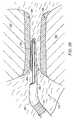
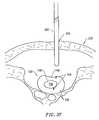
- High frequency voltagecan then be applied between one or more active electrode(s) and one or more return electrode(s) to apply sufficient energy to the disc tissue to substantially seal the fissure on the annulus.
- the high frequency voltagewill be directed only to the tissue immediately surrounding the fissure so as to reduce collateral heating and damage to the annulus tissue and nucleus pulposus.
- electrically conducting fluidsuch as isotonic saline
- the conductive fluidwill typically be delivered such that the fluid substantially surrounds the active electrode, and provides a layer of fluid between the active electrode and the tissue.
- the conductive fluidpreferably generates a current flow path between the active electrode(s) and one or more return electrode(s).
- the current flow pathmay be generated by directing an electrically conducting fluid along a fluid path past the return electrode and to the fissure, or by locating a viscous electrically conducting fluid, such as a gel, at the fissure, and submersing the active electrode(s) and the return electrode(s) within the conductive gel.
- the fissuremay be heated either by passing the electric current through the tissue to a selected depth before the current returns to the return electrode(s) and/or by heating the electrically conducting fluid in contact with the fissure.
- the electric currentmay not pass into the tissue surrounding the fissure at all.
- the heated fluid and/or the electric currentelevates the temperature of the annulus tissue surrounding the fissure sufficiently to cause sealing of the fissure.
- the high frequency voltageis applied to the active electrode(s) to elevate the temperature of tissue immediately surrounding the fissure from body temperature (about 37° C.) to a tissue temperature in the range of about 45° C. to 90° C., usually about 60° C. to 70° C., to seal the fissure.
- the present inventionprovides a method of treating a fissure.
- a sealant or bonding materialsuch as a fibrogen glue or collagen, is delivered to the fissure.
- the sealantcan be heated so as to seal the fissure.
- the sealantis directed through a tube or a catheter and onto the fissure.
- the tubecan be disposed within the probe or a separate instrument.
- An opening or a plurality of openingscan be disposed near the distal end of the tube or along the lumen of the tube to deliver the sealant from the tube to the fissure.
- high frequency energysuch as RF
- the high frequency energycan be applied in a sufficient amount to effectively cause the sealant to harden while avoiding damage to the surrounding tissue.
- the present inventionprovides an electrosurgical apparatus for treating a fissure in the annulus.
- the apparatuscomprises an elongate shaft having a proximal end portion and a distal end portion.
- An active electrodeis disposed on the distal end portion of the shaft.
- the apparatusfurther comprises a return electrode and a high frequency voltage source which can generate a voltage sufficient to seal the fissure.
- the probewill typically have a suitable diameter and length to allow the surgeon to reach the fissure by delivering the shaft through a percutaneous penetration in the thoracic cavity, the abdomen, the back, or the like.
- the shaft of the probemay be rigid or flexible. In most embodiments, however, the shaft of the probe is semi-flexible or catheter like so as to permit the treating physician to direct the electrode from a proximal end of the shaft to the target disc.
- the probemay be introduced through a percutaneous penetration in the body and to the target disc through a rigid external tube or a trocar cannula.
- a trephine or other conventional instrumentmay be used to form a channel from the trocar cannula through the annulus fibrosus and into the nucleus pulposus.
- the probe of the present inventionmay use a single active electrode or an electrode array distributed over a contact surface of a probe.
- the electrode arrayusually includes a plurality of independently current-limited and/or power-controlled active electrodes to apply electrical energy selectively to the target tissue while limiting the unwanted application of electrical energy to the surrounding tissue and environment resulting from power dissipation into surrounding electrically conductive liquids, such as blood, normal saline, electrically conductive gel and the like.
- the active electrodesare disposed in a linear arrangement near or at the distal end of the probe so as to define an edge which can promote localized electric fields between the edge and the fissure.
- the use of the linear electrodesincrease the electric field intensity and reduce the extent or depth of tissue heating as a consequence of the divergence of current flux lines which emanate from the exposed surface of each active electrode.
- the linear electrodesprovide an interface which can engage an approximately linear fissure and focus the electrical energy directly to the tissue within the fissure. As a result, the linear arrangement can improve the sealing of the fissure and reduce the collateral damage to the surrounding tissue.
- the return electrodeis disposed on the shaft and spaced apart from the active electrode. An electrical current is passed between the active electrode and the return electrode.
- the return electrodeis a dispersive pad, and the electrical current is passed directly through a patient's tissue.
- the systemfurther comprises a fluid delivery element for supplying electrically conductive fluid to the fissure to substantially surround at least the active electrode with electrically conductive fluid and to locate electrically conductive fluid between the active electrode and the fissure.
- the fluid delivery elementmay be located on the probe, e.g., a fluid lumen or tube, or it may be part of a separate instrument.
- a high frequency voltage sourcegenerates a voltage sufficient to seal the fissure.
- the electrically conducting fluidwill preferably generate a current flow path between the active electrode(s) and one or more return electrode(s).
- the return electrodeis located on the probe and spaced a sufficient distance from the active electrode(s) to substantially avoid or minimize current shorting therebetween and to shield the return electrode from tissue at the target site.
- the present inventionmay be used to both ablate or shrink a portion of the nucleus pulposus, to reduce the water content of the nucleus pulposus which will reduce the pressure of the nucleus pulposus on the annulus.
- the RF energyheats the tissue directly by virtue of the electrical current flow therethrough, and/or indirectly through the exposure of the tissue to fluid heated by RF energy, to elevate the tissue temperature from normal body temperatures (e.g. 37° C.) to temperatures in the range of 45° C. to 90° C., preferably in the range from about 60° C. to 70° C.
- the system and methods of the present inventionmay optionally include a temperature controller coupled to one or more temperature sensors at or near the distal end of the probe.
- the controlleradjusts the output voltage of the power supply in response to a temperature set point and the measured temperature value.
- the temperature sensormay be, for example, a thermocouple, located in the insulating support that measures a temperature at the distal end of the probe.
- the temperature set pointwill preferably be one that corresponds to a tissue temperature that results, for example, in the contraction of the collagen tissue, i.e., about 60° C. to 70° C.
- the temperature sensormay directly measure the tissue temperature (e.g., infrared sensor).
- FIG. 1is a perspective view of an electrosurgical system incorporating a power supply and an electrosurgical probe for tissue ablation, resection, incision, contraction and for vessel hemostasis according to the present invention
- FIG. 2is a side view of an electrosurgical probe according to the present invention.
- FIG. 3is a cross-sectional view of a distal portion of the probe of FIG. 2;
- FIG. 4is an end view of the probe of FIG. 2, illustrating an array of active electrodes
- FIG. 5is an exploded view of the electrical connections within the probe of FIG. 2;
- FIGS. 6-10are end views of alternative embodiments of the probe of FIG. 2, incorporating aspiration electrode(s);
- FIGS. 11A-11Cillustrate an alternative embodiment incorporating a mesh electrode for ablating aspirated tissue fragments
- FIGS. 12-15illustrate a method of performing a microendoscopic discectomy according to the principles of the present invention
- FIG. 16is a schematic view of the proximal portion of another electrosurgical system for endoscopic spine surgery incorporating an electrosurgical instrument according to the present invention
- FIG. 17is an enlarged view of a distal portion of the electrosurgical instrument of FIG. 16;
- FIG. 18illustrates a method of ablating a volume of tissue from the nucleus pulposus of a herniated disc with the electrosurgical system of FIG. 16;
- FIG. 19illustrates a planar ablation probe for ablating tissue in confined spaces within a patient's body according to the present invention
- FIG. 20illustrates a distal portion of the planar ablation probe of FIG. 19
- FIG. 21Ais a front sectional view of the planar ablation probe, illustrating an array of semi-cylindrical active electrodes
- FIG. 21Bis a front sectional view of an alternative planar ablation probe, illustrating an array of active electrodes having opposite polarities;
- FIG. 22is a top, partial section, view of the working end of the planar ablation probe of FIG. 19;
- FIG. 23is a side cross-sectional view of the working end of the planar ablation probe, illustrating the electrical connection with one of the active electrodes of FIG. 22;
- FIG. 24is a side cross-sectional view of the proximal end of the planar ablation probe, illustrating the electrical connection with a power source connector;
- FIG. 25is a schematic view illustrating the ablation of meniscus tissue located close to articular cartilage between the tibia and femur of a patient with the ablation probe of FIG. 19;
- FIG. 26is an enlarged view of the distal portion of the planar ablation probe, illustrating ablation or cutting of meniscus tissue
- FIG. 27illustrates a method of ablating tissue with a planar ablation probe incorporating a single active electrode
- FIG. 28is a schematic view illustrating the ablation of soft tissue from adjacent surfaces of the vertebrae with the planar ablation probe of the present invention.
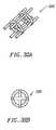
- FIG. 29is a perspective view of an alternative embodiment of the planar ablation probe incorporating a ceramic support structure with conductive strips printed thereon;
- FIG. 30is a top partial cross-sectional view of the planar ablation probe of FIG. 29;
- FIG. 31is an end view of the probe of FIG. 30;
- FIGS. 32A and 32Billustrate an alternative cage aspiration electrode for use with the electrosurgical probes shown in FIGS. 2-11;
- FIGS. 33A-33Cillustrate an alternative dome shaped aspiration electrode for use with the electrosurgical probes of FIGS. 2-11;
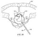
- FIGS. 34-36illustrates another system and method of the present invention for percutaneously contracting collagen fibers within a spinal disc with a small, needle-sized instrument.
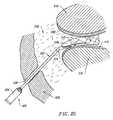
- FIG. 37is a partial cross-section of an intervertebral disc having fissures on the inner surface and outer surfaces thereof;
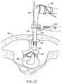
- FIG. 38illustrates a method of sealing a fissure on the outer surface of the annulus of the disc
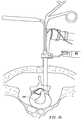
- FIG. 39illustrates a method of sealing a fissure on the inner surface of the annulus disc.
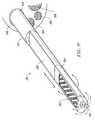
- FIG. 40illustrates one embodiment of a device for sealing a fissure in the annulus
- the present inventionprovides systems and methods for selectively applying electrical energy to a target location within or on a patient's body, particularly including tissue or other body structures in the spine.
- These proceduresinclude laminectomy/discectomy procedures for treating herniated disks, decompressive laminectomy for stenosis in the lumbosacral and cervical spine, medial facetectomy, posterior lumbosacral and cervical spine fusions, treatment of scoliosis associated with vertebral disease, foraminotomies to remove the roof of the intervertebral foramina to relieve nerve root compression and anterior cervical and lumbar diskectomies.
- These proceduresmay be performed through open procedures, or using minimally invasive techniques, such as thoracoscopy, arthroscopy, laparascopy or the like.
- high frequency (RF) electrical energyis applied to one or more active electrodes in the presence of electrically conductive fluid to remove and/or modify the structure of tissue structures.
- the present inventionmay be used to: (1) volumetrically remove tissue, bone, ligament or cartilage (i.e., ablate or effect molecular dissociation of the body structure); (2) cut or resect tissue or other body structures; (3) shrink or contract collagen connective tissue; (4) coagulate severed blood vessels; and/or (5) seal fissures or other openings
- the RF energyheats the tissue directly by virtue of the electrical current flow therethrough, and/or indirectly through the exposure of the tissue to fluid heated by RF energy, to elevate the tissue temperature from normal body temperatures (e.g., 37° C.) to temperatures in the range of 45° C. to 90° C., preferably in the range from about 60° C. to 70° C.
- Thermal shrinkage of collagen fibersoccurs within a small temperature range which, for mammalian collagen is in the range from 60° C. to 70° C.
- the preferred depth of heating to effect the shrinkage of collagen in the heated regioni.e., the depth to which the tissue is elevated to temperatures between 60° C. to 70° C.
- the depth of heatingis usually in the range from 0 to 3.5 mm. In the case of collagen within the nucleus pulposus, the depth of heating is preferably in the range from about 0 to about 2.0 mm.
- the tissue structuresare volumetrically removed or ablated.
- a high frequency voltage differenceis applied between one or more active electrode(s) and one or more return electrode(s) to develop high electric field intensities in the vicinity of the target tissue site.
- the high electric field intensitieslead to electric field induced molecular breakdown of target tissue through molecular dissociation (rather than thermal evaporation or carbonization).
- Applicantbelieves that the tissue structure is volumetrically removed through molecular disintegration of larger organic molecules into smaller molecules and/or atoms, such as hydrogen, oxides of carbon, hydrocarbons and nitrogen compounds. This molecular disintegration completely removes the tissue structure, as opposed to dehydrating the tissue material by the removal of liquid within the cells of the tissue, as is typically the case with electrosurgical desiccation and vaporization.
- the high electric field intensitiesmay be generated by applying a high frequency voltage that is sufficient to vaporize an electrically conducting fluid over at least a portion of the active electrode(s) in the region between the distal tip of the active electrode(s) and the target tissue.
- the electrically conductive fluidmay be a gas or liquid, such as isotonic saline, delivered to the target site, or a viscous fluid, such as a gel, that is located at the target site. In the latter embodiment, the active electrode(s) are submersed in the electrically conductive gel during the surgical procedure.
- the vapor layer or vaporized regionSince the vapor layer or vaporized region has a relatively high electrical impedance, it increases the voltage differential between the active electrode tip and the tissue and causes ionization within the vapor layer due to the presence of an ionizable species (e.g., sodium when isotonic saline is the electrically conducting fluid). This ionization, under optimal conditions, induces the discharge of energetic electrons and photons from the vapor layer and to the surface of the target tissue. This energy may be in the form of energetic photons (e.g., ultraviolet radiation), energetic particles (e.g., electrons) or a combination thereof.
- CoblationTMA more detailed description of this cold ablation phenomena, termed CoblationTM, can be found in commonly assigned U.S. Pat. No. 5,683,366 the complete disclosure of which is incorporated herein by reference.
- the present inventionapplies high frequency (RF) electrical energy in an electrically conducting fluid environment to remove (i.e., resect, cut or ablate) or contract a tissue structure, and to seal transected vessels within the region of the target tissue.
- RFhigh frequency
- the present inventionis particularly useful for sealing larger arterial vessels, e.g., on the order of 1 mm or greater.
- a high frequency power supplyis provided having an ablation mode, wherein a first voltage is applied to an active electrode sufficient to effect molecular dissociation or disintegration of the tissue, and a coagulation mode, wherein a second, lower voltage is applied to an active electrode (either the same or a different electrode) sufficient to achieve hemostasis of severed vessels within the tissue.
- an electrosurgical probehaving one or more coagulation electrode(s) configured for sealing a severed vessel, such as an arterial vessel, and one or more active electrodes configured for either contracting the collagen fibers within the tissue or removing (ablating) the tissue, e.g., by applying sufficient energy to the tissue to effect molecular dissociation.
- the coagulation electrode(s)may be configured such that a single voltage can be applied to coagulate with the coagulation electrode(s), and to ablate or contract with the active electrode(s).
- the power supplyis combined with the coagulation probe such that the coagulation electrode is used when the power supply is in the coagulation mode (low voltage), and the active electrode(s) are used when the power supply is in the ablation mode (higher voltage).
- one or more active electrodesare brought into close proximity to tissue at a target site, and the power supply is activated in the ablation mode such that sufficient voltage is applied between the active electrodes and the return electrode to volumetrically remove the tissue through molecular dissociation, as described below.
- the power supplyis activated in the ablation mode such that sufficient voltage is applied between the active electrodes and the return electrode to volumetrically remove the tissue through molecular dissociation, as described below.
- vessels within the tissuewill be severed. Smaller vessels will be automatically sealed with the system and method of the present invention. Larger vessels, and those with a higher flow rate, such as arterial vessels, may not be automatically sealed in the ablation mode. In these cases, the severed vessels may be sealed by activating a control (e.g., a foot pedal) to reduce the voltage of the power supply into the coagulation mode.
- a controle.g., a foot pedal
- the active electrodesmay be pressed against the severed vessel to provide sealing and/or coagulation of the vessel.
- a coagulation electrode located on the same or a different probemay be pressed against the severed vessel.
- the present inventionis particularly useful for removing or ablating tissue around nerves, such as spinal or cranial nerves, e.g., the spinal cord and the surrounding dura mater.
- nervessuch as spinal or cranial nerves, e.g., the spinal cord and the surrounding dura mater.
- One of the significant drawbacks with the prior art cutters, graspers, and lasersis that these devices do not differentiate between the target tissue and the surrounding nerves or bone. Therefore, the surgeon must be extremely careful during these procedures to avoid damage to the bone or nerves within and around the spinal cord.
- the CoblationTM process for removing tissueresults in extremely small depths of collateral tissue damage as discussed above. This allows the surgeon to remove tissue close to a nerve without causing collateral damage to the nerve fibers.
- Nervesusually comprise a connective tissue sheath, or endoneurium, enclosing the bundles of nerve fibers to protect these nerve fibers.
- This protective tissue sheathtypically comprises a fatty tissue (e.g., adipose tissue) having substantially different electrical properties than the normal target tissue, such as the disc and other surrounding tissue that are, for example, removed from the spine during spinal procedures.
- the system of the present inventionmeasures the electrical properties of the tissue at the tip of the probe with one or more active electrode(s). These electrical properties may include electrical conductivity at one, several or a range of frequencies (e.g., in the range from 1 kHz to 100 MHz), dielectric constant, capacitance or combinations of these.
- an audible signalmay be produced when the sensing electrode(s) at the tip of the probe detects the fatty tissue surrounding a nerve, or direct feedback control can be provided to only supply power to the active electrode(s) either individually or to the complete array of electrodes, if and when the tissue encountered at the tip or working end of the probe is normal tissue based on the measured electrical properties.
- the current limiting elementsare configured such that the active electrodes will shut down or turn off when the electrical impedance reaches a threshold level.
- a threshold levelis set to the impedance of the fatty tissue surrounding nerves, the active electrodes will shut off whenever they come in contact with, or in close proximity to, nerves. Meanwhile, the other active electrodes, which are in contact with or in close proximity to nasal tissue, will continue to conduct electric current to the return electrode.
- the Coblation® mechanism of the present inventioncan be manipulated to ablate or remove certain tissue structures, while having little effect on other tissue structures.
- the present inventionuses a technique of vaporizing electrically conductive fluid to form a plasma layer or pocket around the active electrode(s), and then inducing the discharge of energy from this plasma or vapor layer to break the molecular bonds of the tissue structure. Based on initial experiments, applicants believe that the free electrons within the ionized vapor layer are accelerated in the high electric fields near the electrode tip(s).
- the electron mean free pathincreases to enable subsequently injected electrons to cause impact ionization within these regions of low density (i.e., vapor layers or bubbles).
- Energy evolved by the energetic electronse.g., 4 to 5 eV
- the energy evolved by the energetic electronsmay be varied by adjusting a variety of factors, such as: the number of active electrodes; electrode size and spacing; electrode surface area; asperities and sharp edges on the electrode surfaces; electrode materials; applied voltage and power; current limiting means, such as inductors; electrical conductivity of the fluid in contact with the electrodes; density of the fluid; and other factors. Accordingly, these factors can be manipulated to control the energy level of the excited electrons. Since different tissue structures have different molecular bonds, the present invention can be configured to break the molecular bonds of certain tissue, while having too low an energy to break the molecular bonds of other tissue.
- fatty tissuee.g., adipose
- fatty tissuee.g., adipose
- the present invention in its current configurationgenerally does not ablate or remove such fatty tissue.
- factorsmay be changed such that these double bonds can be broken (e.g., increasing voltage or changing the electrode configuration to increase the current density at the electrode tips).
- the electrosurgical probe or catheterwill comprise a shaft or a handpiece having a proximal end and a distal end which supports one or more active electrode(s).
- the shaft or handpiecemay assume a wide variety of configurations, with the primary purpose being to mechanically support the active electrode and permit the treating physician to manipulate the electrode from a proximal end of the shaft.
- the shaftmay be rigid or flexible, with flexible shafts optionally being combined with a generally rigid external tube for mechanical support. Flexible shafts may be combined with pull wires, shape memory actuators, and other known mechanisms for effecting selective deflection of the distal end of the shaft to facilitate positioning of the electrode array.
- the shaftwill usually include a plurality of wires or other conductive elements running axially therethrough to permit connection of the electrode array to a connector at the proximal end of the shaft.
- the shaftwill have a suitable diameter and length to allow the surgeon to reach the target site (e.g., a disc) by delivering the shaft through the thoracic cavity, the abdomen or the like.
- the shaftwill usually have a length in the range of about 5.0 to 30.0 cm, and a diameter in the range of about 0.2 mm to about 20 mm.
- the shaftmay be delivered directly through the patient's back in a posterior approach, which would considerably reduce the required length of the shaft.
- the shaftmay also be introduced through rigid or flexible endoscopes. Specific shaft designs will be described in detail in connection with the figures hereinafter.
- the probemay comprise a long, thin needle (e.g., on the order of about 1 mm in diameter or less) that can be percutaneously introduced through the patient's back directly into the spine (see FIGS. 34 - 36 ).
- the needlewill include one or more active electrode(s) for applying electrical energy to tissues within the spine.
- the needlemay include one or more return electrode(s), or the return electrode may be positioned on the patient's back, as a dispersive pad. In either embodiment, sufficient electrical energy is applied through the needle to the active electrode(s) to either shrink the collagen fibers within the spinal disk, or to ablate tissue within the disk.
- the current flow path between the active electrode(s) and the return electrode(s)may be generated by submerging the tissue site in an electrical conducting fluid (e.g., within a liquid or a viscous fluid, such as an electrically conductive gel) or by directing an electrically conducting fluid along a fluid path to the target site (i.e., a liquid, such as isotonic saline, or a gas, such as argon).
- an electrical conducting fluide.g., within a liquid or a viscous fluid, such as an electrically conductive gel
- directing an electrically conducting fluid along a fluid path to the target sitei.e., a liquid, such as isotonic saline, or a gas, such as argon.
- the system of the present inventionwill usually include a suction lumen in the probe, or on another instrument, for aspirating fluids from the target site.
- the inventionmay include one or more aspiration electrode(s) coupled to the distal end of the suction lumen for ablating, or at least reducing the volume of, non-ablated tissue fragments that are aspirated into the lumen.
- the aspiration electrode(s)function mainly to inhibit clogging of the lumen that may otherwise occur as larger tissue fragments are drawn therein.
- the aspiration electrode(s)may be different from the ablation active electrode(s), or the same electrode(s) may serve both functions.
- a more complete description of probes incorporating aspiration electrode(s)can be found in commonly assigned, co-pending U.S. patent application Ser. No. 09/010,382, filed Jan. 21, 1998, the complete disclosure of which is incorporated herein by reference.
- the present inventionmay use a single active electrode or an electrode array distributed over a contact surface of a probe.
- the electrode arrayusually includes a plurality of independently current-limited and/or power-controlled active electrodes to apply electrical energy selectively to the target tissue while limiting the unwanted application of electrical energy to the surrounding tissue and environment resulting from power dissipation into surrounding electrically conductive liquids, such as blood, normal saline, electrically conductive gel and the like.
- the active electrodesmay be independently current-limited by isolating the electrodes from each other and connecting each electrode to a separate power source that is isolated from the other active electrodes.
- the active electrodesmay be connected to each other at either the proximal or distal ends of the probe to form a single wire that couples to a power source.
- the active electrode(s)have an active portion or surface with surface geometries shaped to promote the electric field intensity and associated current density along the leading edges of the electrodes. Suitable surface geometries may be obtained by creating electrode shapes that include preferential sharp edges, or by creating asperities or other surface roughness on the active surface(s) of the electrodes. Electrode shapes according to the present invention can include the use of formed wire (e.g., by drawing round wire through a shaping die) to form electrodes with a variety of cross-sectional shapes, such as square, rectangular, L or V shaped, or the like. Electrode edges may also be created by removing a portion of the elongate metal electrode to reshape the cross-section.
- materialcan be ground along the length of a round or hollow wire electrode to form D or C shaped wires, respectively, with edges facing in the cutting direction.
- materialcan be removed at closely spaced intervals along the electrode length to form transverse grooves, slots, threads or the like along the electrodes.
- the active electrode surface(s)may be modified through chemical, electrochemical or abrasive methods to create a multiplicity of surface asperities on the electrode surface. These surface asperities will promote high electric field intensities between the active electrode surface(s) and the target tissue to facilitate ablation or cutting of the tissue.
- surface asperitiesmay be created by etching the active electrodes with etchants having a Ph less than 7.0 or by using a high velocity stream of abrasive particles (e.g., grit blasting) to create asperities on the surface of an elongated electrode.
- the active electrode(s)are typically mounted in an electrically insulating electrode support that extends from the electrosurgical probe.
- the electrode supportcomprises a plurality of wafer layers bonded together, e.g., by a glass adhesive or the like, or a single wafer.
- the wafer layer(s)have conductive strips printed thereon to form the active electrode(s) and the return electrode(s).
- the proximal end of the wafer layer(s)will have a number of holes extending from the conductor strips to an exposed surface of the wafer layers for connection to electrical conductor lead traces in the electrosurgical probe or handpiece.
- the wafer layerspreferably comprise a ceramic material, such as alumina, and the electrode will preferably comprise a metallic material, such as gold, copper, platinum, palladium, tungsten, silver or the like.
- Suitable multilayer ceramic electrodesare commercially available from e.g., VisPro Corporation of Beaverton, Oreg.
- each individual active electrode in the electrode arrayis electrically insulated from all other active electrodes in the array within said probe and is connected to a power source which is isolated from each of the other active electrodes in the array or to circuitry which limits or interrupts current flow to the active electrode when low resistivity material (e.g., blood, electrically conductive saline irrigant or electrically conductive gel) causes a lower impedance path between the return electrode and the individual active electrode.
- the isolated power sources for each individual active electrodemay be separate power supply circuits having internal impedance characteristics which limit power to the associated active electrode when a low impedance return path is encountered.
- the isolated power sourcemay be a user selectable constant current source.
- a single power sourcemay be connected to each of the active electrodes through independently actuatable switches, or by independent current limiting elements, such as inductors, capacitors, resistors and/or combinations thereof.
- the current limiting elementsmay be provided in the probe, connectors, cable, controller or along the conductive path from the controller to the distal tip of the probe.
- the resistance and/or capacitancemay occur on the surface of the active electrode(s) due to oxide layers which form selected active electrodes (e.g., titanium or a resistive coating on the surface of metal, such as platinum).
- the tip region of the probemay comprise many independent active electrodes designed to deliver electrical energy in the vicinity of the tip.
- the selective application of electrical energy to the conductive fluidis achieved by connecting each individual active electrode and the return electrode to a power source having independently controlled or current limited channels.
- the return electrode(s)may comprise a single tubular member of conductive material proximal to the electrode array at the tip which also serves as a conduit for the supply of the electrically conducting fluid between the active and return electrodes.
- the probemay comprise an array of return electrodes at the distal tip of the probe (together with the active electrodes) to maintain the electric current at the tip.
- the application of high frequency voltage between the return electrode(s) and the electrode arrayresults in the generation of high electric field intensities at the distal tips of the active electrodes with conduction of high frequency current from each individual active electrode to the return electrode.
- the current flow from each individual active electrode to the return electrode(s)is controlled by either active or passive means, or a combination thereof, to deliver electrical energy to the surrounding conductive fluid while minimizing energy delivery to surrounding (non-target) tissue.
- the application of a high frequency voltage between the return electrode(s) and the active electrode(s) for appropriate time intervalseffects cutting, removing, ablating, shaping, contracting or otherwise modifying the target tissue.
- the tissue volume over which energy is dissipatedi.e., a high current density exists
- the tissue volume over which energy is dissipatedmay be precisely controlled, for example, by the use of a multiplicity of small active electrodes whose effective diameters or principal dimensions range from about 5 mm to 0.01 mm, preferably from about 2 mm to 0.05 mm, and more preferably from about 1 mm to 0.1 mm.
- Electrode areas for both circular and non-circular electrodeswill have a contact area (per active electrode) below 25 mm 2 , preferably being in the range from 0.0001 mm 2 to 1 mm 2 , and more preferably from 0.005 mm 2 to 0.5 mm 2 .
- the circumscribed area of the electrode arrayis in the range from 0.25 mm 2 to 200 mm 2 , preferably from 0.5 mm 2 to 100 mm 2 , and will usually include at least two isolated active electrodes, preferably at least five active electrodes, often greater than 10 active electrodes and even 50 or more active electrodes, disposed over the distal contact surfaces on the shaft.
- the use of small diameter active electrodesincreases the electric field intensity and reduces the extent or depth of tissue heating as a consequence of the divergence of current flux lines which emanate from the exposed surface of each active electrode.
- the area of the tissue treatment surfacecan vary widely, and the tissue treatment surface can assume a variety of geometries, with particular areas and geometries being selected for specific applications.
- Active electrode surfacescan have areas in the range from 0.25 mm 2 to 75 mm 2 , usually being from about 0.5 mm 2 to 40 mm 2 .
- the geometriescan be planar, concave, convex, hemispherical, conical, linear “in-line” array or virtually any other regular or irregular shape.
- the active electrode(s) or active electrode(s)will be formed at the distal tip of the electrosurgical probe shaft, frequently being planar, disk-shaped, or hemispherical surfaces for use in reshaping procedures or being linear arrays for use in cutting.
- the active electrode(s)may be formed on lateral surfaces of the electrosurgical probe shaft (e.g., in the manner of a spatula), facilitating access to certain body structures in endoscopic procedures.
- the electrically conducting fluidshould have a threshold conductivity to provide a suitable conductive path between the return electrode(s) and the active electrode(s).
- the electrical conductivity of the fluid(in units of milliSiemans per centimeter or mS/cm) will usually be greater than 0.2 mS/cm, preferably will be greater than 2 mS/cm and more preferably greater than 10 mS/cm.
- the electrically conductive fluidis isotonic saline, which has a conductivity of about 17 mS/cm.
- the fluidmay be an electrically conductive gel or spray, such as a saline electrolyte gel, a conductive ECG spray, an electrode conductivity gel, an ultrasound transmission or scanning gel, or the like.
- Suitable gels or spraysare commercially available from Graham-Field, Inc of Hauppauge, N.Y.
- the electrode support and the fluid outletmay be recessed from an outer surface of the probe or handpiece to confine the electrically conductive fluid to the region immediately surrounding the electrode support.
- the shaftmay be shaped so as to form a cavity around the electrode support and the fluid outlet. This helps to assure that the electrically conductive fluid will remain in contact with the active electrode(s) and the return electrode(s) to maintain the conductive path therebetween. In addition, this will help to maintain a vapor or plasma layer between the active electrode(s) and the tissue at the treatment site throughout the procedure, which reduces the thermal damage that might otherwise occur if the vapor layer were extinguished due to a lack of conductive fluid. Provision of the electrically conductive fluid around the target site also helps to maintain the tissue temperature at desired levels.
- the voltage applied between the return electrode(s) and the electrode arraywill be at high or radio frequency, typically between about 5 kHz and 20 MHz, usually being between about 30 kHz and 2.5 MHz, preferably being between about 50 kHz and 500 kHz, more preferably less than 350 kHz, and most preferably between about 100 kHz and 200 kHz.
- the RMS (root mean square) voltage appliedwill usually be in the range from about 5 volts to 1000 volts, preferably being in the range from about 10 volts to 500 volts depending on the active electrode size, the operating frequency and the operation mode of the particular procedure or desired effect on the tissue (i.e., contraction, coagulation or ablation).
- the peak-to-peak voltagewill be in the range of 10 to 2000 volts, preferably in the range of 20 to 1200 volts and more preferably in the range of about 40 to 800 volts (again, depending on the electrode size, the operating frequency and the operation mode).
- the voltageis usually delivered in a series of voltage pulses or alternating current of time varying voltage amplitude with a sufficiently high frequency (e.g., on the order of 5 kHz to 20 MHz) such that the voltage is effectively applied continuously (as compared with e.g., lasers claiming small depths of necrosis, which are generally pulsed about 10 to 20 Hz).
- the duty cyclei.e., cumulative time in any one-second interval that energy is applied
- the preferred power source of the present inventiondelivers a high frequency current selectable to generate average power levels ranging from several milliwatts to tens of watts per electrode, depending on the volume of target tissue being heated, and/or the maximum allowed temperature selected for the probe tip.
- the power sourceallows the user to select the voltage level according to the specific requirements of a particular spine procedure, arthroscopic surgery, dermatological procedure, ophthalmic procedures, FESS procedure, open surgery or other endoscopic surgery procedure.
- a description of a suitable power sourcecan be found in U.S. Provisional Patent Application No. 60/062,997 entitled, filed Oct. 23, 1997, the complete disclosure of which has been incorporated herein by reference.
- the power sourcemay be current limited or otherwise controlled so that undesired heating of the target tissue or surrounding (non-target) tissue does not occur.
- current limiting inductorsare placed in series with each independent active electrode, where the inductance of the inductor is in the range of 10 uH to 50,000 uH, depending on the electrical properties of the target tissue, the desired tissue heating rate and the operating frequency.
- capacitor-inductor (LC) circuit structuresmay be employed, as described previously in co-pending PCT application No. PCT/US94/05168, the complete disclosure of which is incorporated herein by reference. Additionally, current limiting resistors may be selected.
- these resistorswill have a large positive temperature coefficient of resistance so that, as the current level begins to rise for any individual active electrode in contact with a low resistance medium (e.g., saline irrigant or conductive gel), the resistance of the current limiting resistor increases significantly, thereby minimizing the power delivery from said active electrode into the low resistance medium (e.g., saline irrigant or conductive gel).
- a low resistance mediume.g., saline irrigant or conductive gel
- the inventionis not limited to electrically isolated active electrodes, or even to a plurality of active electrodes.
- the array of active electrodesmay be connected to a single lead that extends through the probe shaft to a power source of high frequency current.
- the probemay incorporate a single electrode that extends directly through the probe shaft or is connected to a single lead that extends to the power source.
- the active electrodemay have a ball shape (e.g., for tissue vaporization and desiccation), a twizzle shape (for vaporization and needle-like cutting), a spring shape (for rapid tissue debulking and desiccation), a twisted metal shape, an annular or solid tube shape or the like.
- the electrodemay comprise a plurality of filaments, a rigid or flexible brush electrode (for debulking a tumor, such as a fibroid, bladder tumor or a prostate adenoma), a side-effect brush electrode on a lateral surface of the shaft, a coiled electrode or the like.
- the probecomprises a single active electrode that extends from an insulating member, e.g., ceramic, at the distal end of the probe.
- the insulating memberis preferably a tubular structure that separates the active electrode from a tubular or annular return electrode positioned proximal to the insulating member and the active electrode.
- Electrosurgical system 11generally comprises an electrosurgical handpiece or probe 10 connected to a power supply 28 for providing high frequency voltage to a target site and a fluid source 21 for supplying electrically conducting fluid 50 to probe 10 .
- electrosurgical system 11may include an endoscope (not shown) with a fiber optic head light for viewing the surgical site, particularly in endoscopic spine procedures.
- the endoscopemay be integral with probe 10 , or it may be part of a separate instrument.
- the system 11may also include a vacuum source (not shown) for coupling to a suction lumen or tube 211 (see FIG. 2) in the probe 10 for aspirating the target site.
- probe 10generally includes a proximal handle 19 and an elongate shaft 18 having an array 12 of active electrodes 58 at its distal end.
- a connecting cable 34has a connector 26 for electrically coupling the active electrodes 58 to power supply 28 .
- the active electrodes 58are electrically isolated from each other and each of the electrodes 58 is connected to an active or passive control network within power supply 28 by means of a plurality of individually insulated conductors (not shown).
- a fluid supply tube 15is connected to a fluid tube 14 of probe 10 for supplying electrically conducting fluid 50 to the target site.
- Power supply 28has an operator controllable voltage level adjustment 30 to change the applied voltage level, which is observable at a voltage level display 32 .
- Power supply 28also includes first, second and third foot pedals 37 , 38 , 39 and a cable 36 which is removably coupled to power supply 28 .
- the foot pedals 37 , 38 , 39allow the surgeon to remotely adjust the energy level applied to active electrodes 58 .
- first foot pedal 37is used to place the power supply into the “ablation” mode and second foot pedal 38 places power supply 28 into the “coagulation” mode.
- the third foot pedal 39allows the user to adjust the voltage level within the “ablation” mode.
- a sufficient voltageis applied to the active electrodes to establish the requisite conditions for molecular dissociation of the tissue (i.e., vaporizing a portion of the electrically conductive fluid, ionizing charged particles within the vapor layer and accelerating these charged particles against the tissue).
- the requisite voltage level for ablationwill vary depending on the number, size, shape and spacing of the electrodes, the distance in which the electrodes extend from the support member, etc.
- the power supply 28applies a low enough voltage to the active electrodes (or the coagulation electrode) to avoid vaporization of the electrically conductive fluid and subsequent molecular dissociation of the tissue.
- the surgeonmay automatically toggle the power supply between the ablation and coagulation modes by alternatively stepping on foot pedals 37 , 38 , respectively. This allows the surgeon to quickly move between coagulation and ablation in situ, without having to remove his/her concentration from the surgical field or without having to request an assistant to switch the power supply.
- the probetypically will simultaneously seal and/or coagulation small severed vessels within the tissue.
- FIGS. 2-5illustrate an exemplary electrosurgical probe 20 constructed according to the principles of the present invention.
- probe 20generally includes an elongated shaft 100 which may be flexible or rigid, a handle 204 coupled to the proximal end of shaft 100 and an electrode support member 102 coupled to the distal end of shaft 100 .
- Shaft 100preferably comprises a plastic material that is easily molded into the shape shown in FIG. 2 .
- shaft 100comprises an electrically conducting material, usually metal, which is selected from the group comprising tungsten, stainless steel alloys, platinum or its alloys, titanium or its alloys, molybdenum or its alloys, and nickel or its alloys.
- shaft 100includes an electrically insulating jacket 108 , which is typically formed as one or more electrically insulating sheaths or coatings, such as polytetrafluoroethylene, polyimide, and the like.
- electrically insulating jacket 108is typically formed as one or more electrically insulating sheaths or coatings, such as polytetrafluoroethylene, polyimide, and the like.
- the provision of the electrically insulating jacket over the shaftprevents direct electrical contact between these metal elements and any adjacent body structure or the surgeon. Such direct electrical contact between a body structure (e.g., tendon) and an exposed electrode could result in unwanted heating and necrosis of the structure at the point of contact causing necrosis.
- Handle 204typically comprises a plastic material that is easily molded into a suitable shape for handling by the surgeon. Handle 204 defines an inner cavity (not shown) that houses the electrical connections 250 (FIG. 5 ), and provides a suitable interface for connection to an electrical connecting cable 22 (see FIG. 1 ). Electrode support member 102 extends from the distal end of shaft 100 (usually about 1 to 20 mm), and provides support for a plurality of electrically isolated active electrodes 104 (see FIG. 4 ). As shown in FIG. 2, a fluid tube 233 extends through an opening in handle 204 , and includes a connector 235 for connection to a fluid supply source, for supplying electrically conductive fluid to the target site.
- Fluid tube 233is coupled to a distal fluid tube 239 that extends along the outer surface of shaft 100 to an opening 237 at the distal end of the probe 20 , as discussed in detail below.
- fluid tube 233may extend through a single lumen (not shown) in shaft 100 , or it may be coupled to a plurality of lumens (also not shown) that extend through shaft 100 to a plurality of openings at its distal end.
- Probe 20may also include a valve 17 (FIG. 1) or equivalent structure for controlling the flow rate of the electrically conducting fluid to the target site.
- electrode support member 102has a substantially planar tissue treatment surface 212 and comprises a suitable insulating material (e.g., ceramic or glass material, such as alumina, zirconia and the like) which could be formed at the time of manufacture in a flat, hemispherical or other shape according to the requirements of a particular procedure.
- a suitable insulating materiale.g., ceramic or glass material, such as alumina, zirconia and the like
- the preferred support member materialis alumina, available from Kyocera Industrial Ceramics Corporation, Elkgrove, Ill., because of its high thermal conductivity, good electrically insulative properties, high flexural modulus, resistance to carbon tracking, biocompatibility, and high melting point.
- the support member 102is adhesively joined to a tubular support member (not shown) that extends most or all of the distance between support member 102 and the proximal end of probe 20 .
- the tubular memberpreferably comprises an electrically insulating material, such as an epoxy or silicone-based material.
- active electrodes 104extend through pre-formed openings in the support member 102 so that they protrude above tissue treatment surface 212 by the desired distance.
- the electrodesare then bonded to the tissue treatment surface 212 of support member 102 , typically by an inorganic sealing material.
- the sealing materialis selected to provide effective electrical insulation, and good adhesion to both the alumina member 102 and the platinum or titanium active electrodes 104 .
- the sealing materialadditionally should have a compatible thermal expansion coefficient and a melting point well below that of platinum or titanium and alumina or zirconia, typically being a glass or glass ceramic.
- probe 20includes a return electrode 112 for completing the current path between active electrodes 104 and a high frequency power supply 28 (see FIG. 1 ).
- return electrode 112preferably comprises an annular conductive band coupled to the distal end of shaft 100 slightly proximal to tissue treatment surface 212 of electrode support member 102 , typically about 0.5 to 10 mm and more preferably about 1 to 10 mm.
- Return electrode 112is coupled to a connector 258 that extends to the proximal end of probe 10 , where it is suitably connected to power supply 10 (FIG. 1 ).
- return electrode 112is not directly connected to active electrodes 104 .
- electrically conducting fluide.g., isotonic saline
- the electrically conducting fluidis delivered through an external fluid tube 239 to opening 237 , as described above.
- the fluidmay be delivered by a fluid delivery element (not shown) that is separate from probe 20 .
- the trocar cannulamay be flooded with isotonic saline and the probe 20 will be introduced into this flooded cavity. Electrically conducting fluid will be continually resupplied with a separate instrument to maintain the conduction path between return electrode 112 and active electrodes 104 .
- the fluid pathmay be formed in probe 20 by, for example, an inner lumen or an annular gap between the return electrode and a tubular support member within shaft 100 (not shown).
- This annular gapmay be formed near the perimeter of the shaft 100 such that the electrically conducting fluid tends to flow radially inward towards the target site, or it may be formed towards the center of shaft 100 so that the fluid flows radially outward.
- a fluid sourcee.g., a bag of fluid elevated above the surgical site or having a pumping device
- a fluid supply tube(not shown) that may or may not have a controllable valve.
- the electrically isolated active electrodes 104are spaced apart over tissue treatment surface 212 of electrode support member 102 .
- the tissue treatment surface and individual active electrodes 104will usually have dimensions within the ranges set forth above.
- the tissue treatment surface 212has a circular cross-sectional shape with a diameter in the range of about 1 mm to 30 mm, usually about 2 to 20 mm.
- the individual active electrodes 104preferably extend outward from tissue treatment surface 212 by a distance of about 0.1 to 8 mm, usually about 0.2 to 4 mm. Applicant has found that this configuration increases the high electric field intensities and associated current densities around active electrodes 104 to facilitate the ablation of tissue as described in detail above.
- the probeincludes a single, larger opening 209 in the center of tissue treatment surface 212 , and a plurality of active electrodes (e.g., about 3-15) around the perimeter of surface 212 (see FIG. 3 ).
- the probemay include a single, annular, or partially annular, active electrode at the perimeter of the tissue treatment surface.
- the central opening 209is coupled to a suction or aspiration lumen 213 (see FIG. 2) within shaft 100 and a suction tube 211 (FIG. 2) for aspirating tissue, fluids and/or gases from the target site.
- the electrically conductive fluidgenerally flows from opening 237 of fluid tube 239 radially inward past active electrodes 104 and then back through the central opening 209 of support member 102 .
- Aspirating the electrically conductive fluid during surgeryallows the surgeon to see the target site, and it prevents the fluid from flowing into the patient's body, e.g., into the spine, the abdomen or the thoracic cavity. This aspiration should be controlled, however, so that the conductive fluid maintains a conductive path between the active electrode(s) and the return electrode.
- the distal tip of probemay have a variety of different configurations.
- the probemay include a plurality of openings 209 around the outer perimeter of tissue treatment surface 212 (this embodiment not shown in the drawings).
- the active electrodes 104extend from the center of tissue treatment surface 212 radially inward from openings 209 .
- the openingsare suitably coupled to fluid tube 233 for delivering electrically conductive fluid to the target site, and aspiration lumen 213 for aspirating the fluid after it has completed the conductive path between the return electrode 112 and the active electrodes 104 .
- the probe 20will also include one or more aspiration electrode(s) coupled to the aspiration lumen for inhibiting clogging during aspiration of tissue fragments from the surgical site.
- one or more of the active electrodes 104may comprise loop electrodes 140 that extend across distal opening 209 of the suction lumen within shaft 100 .
- two of the active electrodes 104comprise loop electrodes 140 that cross over the distal opening 209 .
- the electrodesmay have shapes other than loops, such as the coiled configurations shown in FIGS. 6 and 7.
- the electrodesmay be formed within suction lumen proximal to the distal opening 209 , as shown in FIG. 8 .
- the main function of loop electrodes 140is to ablate portions of tissue that are drawn into the suction lumen to prevent clogging of the lumen.
- Loop electrodes 140are electrically isolated from the other active electrodes 104 , which can be referred to hereinafter as the ablation electrodes 104 . Loop electrodes 140 may or may not be electrically isolated from each other. Loop electrodes 140 will usually extend only about 0.05 to 4 mm, preferably about 0.1 to 1 mm from the tissue treatment surface of electrode support member 104 .
- the aspiration electrodesmay comprise a pair of coiled electrodes 150 that extend across distal opening 209 of the suction lumen.
- the larger surface area of the coiled electrodes 150usually increases the effectiveness of the electrodes 150 on tissue fragments passing through opening 209 .
- the aspiration electrodecomprises a single coiled electrode 152 passing across the distal opening 209 of suction lumen. This single electrode 152 may be sufficient to inhibit clogging of the suction lumen.
- the aspiration electrodesmay be positioned within the suction lumen proximal to the distal opening 209 .
- these electrodesare close to opening 209 so that tissue does not clog the opening 209 before it reaches electrodes 154 .
- a separate return electrode 156may be provided within the suction lumen to confine the electric currents therein.
- an aspiration electrode 160within the aspiration lumen 162 of the probe.
- the electrode 160is positioned just proximal of distal opening 209 so that the tissue fragments are ablated as they enter lumen 162 .
- the aspiration electrode 160comprises a loop electrode that stretches across the aspiration lumen 162 .
- the return electrode 164is located outside of the probe as in the previously embodiments.
- the return electrode(s)may be located within the aspiration lumen 162 with the aspiration electrode 160 .
- the inner insulating coating 163may be exposed at portions within the lumen 162 to provide a conductive path between this exposed portion of return electrode 164 and the aspiration electrode 160 .
- the latter embodimenthas the advantage of confining the electric currents to within the aspiration lumen.
- itis usually easier to maintain a conductive fluid path between the active and return electrodes in the latter embodiment because the conductive fluid is aspirated through the aspiration lumen 162 along with the tissue fragments.
- mesh electrode 600extending across the distal portion of aspiration lumen 162 .
- mesh electrode 600includes a plurality of openings 602 to allow fluids and tissue fragments to flow through into aspiration lumen 162 .
- the size of the openings 602will vary depending on a variety of factors.
- the mesh electrodemay be coupled to the distal or proximal surfaces of ceramic support member 102 .
- Wire mesh electrode 600comprises a conductive material, such as titanium, tantalum, steel, stainless steel, tungsten, copper, gold or the like.
- wire mesh electrode 600comprises a different material having a different electric potential than the active electrode(s) 104 .
- mesh electrode 600comprises steel and active electrode(s) comprises tungsten. Applicant has found that a slight variance in the electrochemical potential of mesh electrode 600 and active electrode(s) 104 improves the performance of the device. Of course, it will be recognized that the mesh electrode may be electrically insulated from active electrode(s) as in previous embodiments.
- metal screen 610has a plurality of peripheral openings 612 for receiving active electrodes 104 , and a plurality of inner openings 614 for allowing aspiration of fluid and tissue through opening 609 of the aspiration lumen. As shown, screen 610 is press fitted over active electrodes 104 and then adhered to shaft 100 of probe 20 . Similar to the mesh electrode embodiment, metal screen 610 may comprise a variety of conductive metals, such as titanium, tantalum, steel, stainless steel, tungsten, copper, gold or the like. In the representative embodiment, metal screen 610 is coupled directly to, or integral with, active electrode(s) 104 . In this embodiment, the active electrode(s) 104 and the metal screen 610 are electrically coupled to each other.
- FIGS. 32 and 33illustrate alternative embodiments of the mesh and screen aspiration electrodes.
- the probemay include a conductive cage electrode 620 that extends into the aspiration lumen 162 (not shown) to increase the effect of the electrode on aspirated tissue.
- FIGS. 33A-33Cillustrate a dome-shaped screen electrode 630 that includes one or more anchors 632 (four in the representative embodiment) for attaching the screen electrode 630 to a conductive spacer 634 .
- Screen electrode 630includes a plurality of holes 631 for allowing fluid and tissue fragments to pass therethrough to aspiration lumen 162 .
- Screen electrode 630is sized to fit within opening 609 of aspiration lumen 162 except for the anchors 632 which include holes 633 for receiving active electrodes 104 .
- Spacer 634includes peripheral holes 636 for receiving active electrodes 104 and a central hole 638 aligned with suction lumen 162 .
- Spacer 634may further include insulated holes 640 for electrically isolating screen electrode 630 from active electrodes 104 .
- dome-shaped screen electrode 630preferably extends distally from the probe shaft 100 about the same distance as the active electrodes 104 . Applicant has found that this configuration enhances the ablation rate for tissue adjacent to active electrodes 104 , while still maintaining the ability to ablate aspirated tissue fragments passing through screen 630 .
- FIG. 5illustrates the electrical connections 250 within handle 204 for coupling active electrodes 104 and return electrode 112 to the power supply 28 .
- a plurality of wires 252extend through shaft 100 to couple electrodes 104 to a plurality of pins 254 , which are plugged into a connector block 256 for coupling to a connecting cable 22 (FIG. 1 ).
- return electrode 112is coupled to connector block 256 via a wire 258 and a plug 260 .
- the probe 20further includes an identification element that is characteristic of the particular electrode assembly so that the same power supply 28 can be used for different electrosurgical operations.
- the probe 20includes a voltage reduction element or a voltage reduction circuit for reducing the voltage applied between the active electrodes 104 and the return electrode 112 .
- the voltage reduction elementserves to reduce the voltage applied by the power supply so that the voltage between the active electrodes and the return electrode is low enough to avoid excessive power dissipation into the electrically conducting medium and/or ablation of the soft tissue at the target site.
- the voltage reduction elementprimarily allows the electrosurgical probe 20 to be compatible with other ArthroCare generators that are adapted to apply higher voltages for ablation or vaporization of tissue.
- the voltage reduction elementwill serve to reduce a voltage of about 100 to 135 volts rms (which is a setting of 1 on the ArthroCare Model 970 and 980 (i.e., 2000) Generators) to about 45 to 60 volts rms, which is a suitable voltage for contraction of tissue without ablation (e.g., molecular dissociation) of the tissue.
- the probewill typically not require a voltage reduction element.
- the probemay include a voltage increasing element or circuit, if desired.
- the voltage reduction elementis a dropping capacitor 262 which has first leg 264 coupled to the return electrode wire 258 and a second leg 266 coupled to connector block 256 .
- the capacitormay be located in other places within the system, such as in, or distributed along the length of, the cable, the generator, the connector, etc.
- other voltage reduction elementssuch as diodes, transistors, inductors, resistors, capacitors or combinations thereof, may be used in conjunction with the present invention.
- the probe 90may include a coded resistor (not shown) that is constructed to lower the voltage applied between return electrode 112 and active electrodes 104 to a suitable level for contraction of tissue.
- electrical circuitsmay be employed for this purpose.
- the cable 22 that couples the power supply 10 to the probe 90may be used as a voltage reduction element.
- the cablehas an inherent capacitance that can be used to reduce the power supply voltage if the cable is placed into the electrical circuit between the power supply, the active electrodes and the return electrode.
- the cable 22may be used alone, or in combination with one of the voltage reduction elements discussed above, e.g., a capacitor.
- the probe 20will further include a switch (not shown) or other input that allows the surgeon to couple and decouple the identification element to the rest of the electronics in the probe 20 .
- a switch(not shown) or other input that allows the surgeon to couple and decouple the identification element to the rest of the electronics in the probe 20 .
- the surgeonwill decouple the voltage reduction element from the electronics so that the full voltage applied by the power source is applied to the electrodes on the probe.
- the surgeondesires to reduce the voltage to a suitable level for contraction of tissue, he/she couples the voltage reduction element to the electronics to reduce the voltage applied by the power supply to the active electrodes.
- the present inventioncan be used with a power supply that is adapted to apply a voltage within the selected range for treatment of tissue.
- a voltage reduction element or circuitrymay not be desired.
- the present inventionis particularly useful in microendoscopic discectomy procedures, e.g., for decompressing a nerve root with a lumbar discectomy.
- a percutaneous penetration 270is made in the patients' back 272 so that the superior lamina 274 can be accessed.
- a small needle(not shown) is used initially to localize the disc space level, and a guidewire (not shown) is inserted and advanced under lateral fluoroscopy to the inferior edge of the lamina 274 .
- Sequential cannulated dilators 276are inserted over the guide wire and each other to provide a hole from the incision 220 to the lamina 274 .
- the first dilatormay be used to “palpate” the lamina 274 , assuring proper location of its tip between the spinous process and facet complex just above the inferior edge of the lamina 274 .
- a tubular retractor 278is then passed over the largest dilator down to the lamina 274 .
- the dilators 276are removed, establishing an operating corridor within the tubular retractor 278 .
- an endoscope 280is then inserted into the tubular retractor 278 and a ring clamp 282 is used to secure the endoscope 280 .
- the formation of the operating corridor within retractor 278requires the removal of soft tissue, muscle or other types of tissue that were forced into this corridor as the dilators 276 and retractor 278 were advanced down to the lamina 274 .
- This tissueis usually removed with mechanical instruments, such as pituitary rongeurs, curettes, graspers, cutters, drills, microdebriders and the like.
- mechanical instrumentsgreatly lengthen and increase the complexity of the procedure.
- these instrumentssever blood vessels within this tissue, usually causing profuse bleeding that obstructs the surgeon's view of the target site.
- an electrosurgical probe or catheter 284 as described aboveis introduced into the operating corridor within the retractor 278 to remove the soft tissue, muscle and other obstructions from this corridor so that the surgeon can easily access and visualization the lamina 274 .
- electrically conductive fluid 285is delivered through tube 233 and opening 237 to the tissue (see FIG. 2 ).
- the fluidflows past the return electrode 112 to the active electrodes 104 at the distal end of the shaft.
- the rate of fluid flowis controlled with valve 17 (FIG. 1) such that the zone between the tissue and electrode support 102 is constantly immersed in the fluid.
- the power supply 28is then turned on and adjusted such that a high frequency voltage difference is applied between active electrodes 104 and return electrode 112 .
- the electrically conductive fluidprovides the conduction path (see current flux lines) between active electrodes 104 and the return electrode 112 .
- the high frequency voltageis sufficient to convert the electrically conductive fluid (not shown) between the target tissue and active electrode(s) 104 into an ionized vapor layer or plasma (not shown).
- the applied voltage difference between active electrode(s) 104 and the target tissuei.e., the voltage gradient across the plasma layer
- charged particles in the plasmaviz., electrons
- these charged particlesgain sufficient energy to cause dissociation of the molecular bonds within tissue structures.
- This molecular dissociationis accompanied by the volumetric removal (i.e., ablative sublimation) of tissue and the production of low molecular weight gases, such as oxygen, nitrogen, carbon dioxide, hydrogen and methane.
- the short range of the accelerated charged particles within the tissueconfines the molecular dissociation process to the surface layer to minimize damage and necrosis to the underlying tissue.
- the gaseswill be aspirated through opening 209 and suction tube 211 to a vacuum source.
- excess electrically conductive fluid, and other fluidse.g., blood
- the residual heat generated by the current flux linestypically less than 150° C.
- the surgeonmay switch the power supply 28 into the coagulation mode by lowering the voltage to a level below the threshold for fluid vaporization, as discussed above. This simultaneous hemostasis results in less bleeding and facilitates the surgeon's ability to perform the procedure.
- Another advantage of the present inventionis the ability to precisely ablate soft tissue without causing necrosis or thermal damage to the underlying and surrounding tissues, nerves or bone.
- the voltagecan be controlled so that the energy directed to the target site is insufficient to ablate the lamina 274 so that the surgeon can literally clean the tissue off the lamina 274 , without ablating or otherwise effecting significant damage to the lamina.
- a laminotomy and medial facetectomyis accomplished either with conventional techniques (e.g., Kerrison punch or a high speed drill) or with the electrosurgical probe 284 as discussed above.
- medical retractioncan be achieved with a retractor 288 , or the present invention can be used to ablate with precision the disc.
- epidural veinsare cauterized either automatically or with the coagulation mode of the present invention.
- an annulotomyis necessary, it can be accomplished with a microknife or the ablation mechanism of the present invention while protecting the nerve root with the retractor 288 .
- the herniated disc 290is then removed with a pituitary rongeur in a standard fashion, or once again through ablation as described above.
- the electrosurgical probe of the present inventioncan be used to ablate and/or contract soft tissue within the disc 290 to allow the annulus 292 to repair itself to prevent reoccurrence of this procedure.
- tissue contractiona sufficient voltage difference is applied between the active electrodes 104 and the return electrode 112 to elevate the tissue temperature from normal body temperatures (e.g., 37° C.) to temperatures in the range of 45° C. to 90° C., preferably in the range from 60° C. to 70° C. This temperature elevation causes contraction of the collagen connective fibers within the disc tissue so that the disc 290 withdraws into the annulus 292 .
- an electrically conductive fluidis delivered to the target site as described above, and heated to a sufficient temperature to induce contraction or shrinkage of the collagen fibers in the target tissue.
- the electrically conducting fluidis heated to a temperature sufficient to substantially irreversibly contract the collagen fibers, which generally requires a tissue temperature in the range of about 45° C. to 90° C., usually about 60° C. to 70° C.
- the fluidis heated by applying high frequency electrical energy to the active electrode(s) in contact with the electrically conducting fluid.
- the current emanating from the active electrode(s) 104heats the fluid and generates a jet or plume of heated fluid, which is directed towards the target tissue.
- the heated fluidelevates the temperature of the collagen sufficiently to cause hydrothermal shrinkage of the collagen fibers.
- the return electrode 112draws the electric current away from the tissue site to limit the depth of penetration of the current into the tissue, thereby inhibiting molecular dissociation and breakdown of the collagen tissue and minimizing or completely avoiding damage to surrounding and underlying tissue structures beyond the target tissue site.
- the active electrode(s) 104are held away from the tissue a sufficient distance such that the RF current does not pass into the tissue at all, but rather passes through the electrically conducting fluid back to the return electrode.
- the primary mechanism for imparting energy to the tissueis the heated fluid, rather than the electric current.
- the active electrode(s) 104are brought into contact with, or close proximity to, the target tissue so that the electric current passes directly into the tissue to a selected depth.
- the return electrodedraws the electric current away from the tissue site to limit its depth of penetration into the tissue.
- the depth of current penetrationalso can be varied with the electrosurgical system of the present invention by changing the frequency of the voltage applied to the active electrode and the return electrode. This is because the electrical impedance of tissue is known to decrease with increasing frequency due to the electrical properties of cell membranes which surround electrically conductive cellular fluid.
- an operating frequency of about 100 to 200 kHzis applied to the active electrode(s) to obtain shallow depths of collagen shrinkage (e.g., usually less than 1.5 mm and preferably less than 0.5 mm).
- the size (e.g., diameter or principal dimension) of the active electrodes employed for treating the tissueare selected according to the intended depth of tissue treatment. As described previously in copending patent application PCT International Application, U.S. National Phase Serial No. PCT/US94/05168, the depth of current penetration into tissue increases with increasing dimensions of an individual active electrode (assuming other factors remain constant, such as the frequency of the electric current, the return electrode configuration, etc.).
- the depth of current penetration(which refers to the depth at which the current density is sufficient to effect a change in the tissue, such as collagen shrinkage, irreversible necrosis, etc.) is on the order of the active electrode diameter for the bipolar configuration of the present invention and operating at a frequency of about 100 kHz to about 200 kHz. Accordingly, for applications requiring a smaller depth of current penetration, one or more active electrodes of smaller dimensions would be selected. Conversely, for applications requiring a greater depth of current penetration, one or more active electrodes of larger dimensions would be selected.
- FIGS. 16-18illustrate an alternative electrosurgical system 300 specifically configured for endoscopic discectomy procedures, e.g., for treating extruded or non-extruded herniated discs.
- system 300includes a trocar cannula 302 for introducing a catheter assembly 304 through a percutaneous penetration in the patient to a target disc in the patient's spine.
- the catheter assembly 304may be introduced through the thorax in a thoracoscopic procedure, through the abdomen in a laparascopic procedure, or directly through the patient's back.
- Catheter assembly 304includes a catheter body 306 with a plurality of inner lumens (not shown) and a proximal hub 308 for receiving the various instruments that will pass through catheter body 306 to the target site.
- assembly 304includes an electrosurgical instrument 310 with a flexible shaft 312 , an aspiration catheter 314 , an endoscope 316 and an illumination fiber shaft 318 for viewing the target site.
- aspiration catheter 314includes a distal port 320 and a proximal fitment 322 for attaching catheter 314 to a source of vacuum (not shown).
- Endoscope 316will usually comprise a thin metal tube 317 with a lens 324 at the distal end, and an eyepiece (not shown) at the proximal end.
- electrosurgical instrument 310includes a twist locking stop 330 at a proximal end of the shaft 312 for controlling the axial travel distance T D of the probe. As discussed in detail below, this configuration allows the surgeon to “set” the distance of ablation within the disc.
- instrument 310includes a rotational indicator 334 for displaying the rotational position of the distal portion of instrument 310 to the surgeon. This rotational indicator 334 allows the surgeon to view this rotational position without relying on the endoscope 316 if visualization is difficult, or if an endoscope is not being used in the procedure.
- instrument 310comprises a relatively stiff, but deflectable electrically insulating support cannula 312 and a working end portion 348 movably coupled to cannula 312 for rotational and translational movement of working end 348 .
- Working end 348 of electrosurgical instrument 310can be rotated and translated to ablate and remove a volume of nucleus pulposus within a disc.
- Support cannula 312extends through an internal lumen 344 and beyond the distal end 346 of catheter body 306 .
- support cannula 312may be separate from instrument 310 , or even an integral part of catheter body 306 .
- the distal portion of working end 348includes an exposed return electrode 350 separated from an active electrode array 352 by an insulating support member 354 , such as ceramic.
- electrode array 352is disposed on only one side of ceramic support member 354 so that its other side is insulating and thus atraumatic to tissue.
- Instrument 310will also include a fluid lumen (not shown) having a distal port 360 in working end 348 for delivering electrically conductive fluid to the target site.
- trocar cannula 302is introduced into a percutaneous penetration suitable for endoscopic delivery to the target disc in the spine.
- a trephine (not shown) or other conventional instrumentmay be used to form a channel from the trocar cannula 302 through the annulus fibrosis 370 and into the nucleus pulposus.
- the probe 310may be used for this purpose, as discussed above.
- the working end 348 of instrument 310is then advanced through cannula 302 a short distance (e.g., about 7 to 10 mm) into the nucleus pulposus 372 , as shown in FIG. 18 .
- the mechanical stop 330may then be set at the proximal end of the instrument 310 to limit the axial travel distance of working end 348 . Preferably, this distance will be set to minimize (or completely eliminate) ablation of the surrounding annulus.
- the probeis then energized by applying high frequency voltage difference between the electrode array 352 and return electrode 350 so that electric current flows through the conductive fluid from the array 352 to the return electrode 350 .
- the electric currentcauses vaporization of the fluid and ensuing molecular dissociation of the pulposus tissue as described in detail above.
- the instrument 310may then be translated in an axial direction forwards and backwards to the preset limits. While still energized and translating, the working end 348 may also be rotated to ablate tissue surrounding the electrode array 352 .
- working end 348will also include an inflatable gland 380 opposite electrode array 352 to allow deflection of working end relative to support cannula 312 . As shown in FIG.
- working end 348may be deflected to produce a large diameter bore within the pulposus, which assures close contact with tissue surfaces to be ablated.
- the entire catheter body 306 , or the distal end of catheter body 306may be deflected to increase the volume of pulposus removed.
- instrument 310is withdrawn into catheter body 306 and the catheter body is removed from the patient.
- the preferred volume of removed tissueis about 0.2 to 5 cm 3 .
- FIG. 19illustrates an exemplary planar ablation probe 400 according to the present invention. Similar to the instruments described above, probe 400 can be incorporated into electrosurgical system 11 (or other suitable systems) for operation in either the bipolar or monopolar modalities.
- Probe 400generally includes a support member 402 , a distal working end 404 attached to the distal end of support member 402 and a proximal handle 408 attached to the proximal end of support member 402 .
- handle 406includes a handpiece 408 and a power source connector 410 removably coupled to handpiece 408 for electrically connecting working end 404 with power supply 28 through cable 34 (see FIG. 1 ).
- planar ablation probe 400is configured to operate in the bipolar modality.
- support member 402functions as the return electrode and comprises an electrically conducting material, such as titanium, or alloys containing one or more of nickel, chromium, iron, cobalt, copper, aluminum, platinum, molybdenum, tungsten, tantalum or carbon.
- support member 402is an austenitic stainless steel alloy, such as stainless steel Type 304 from MicroGroup, Inc., Medway, Mass.
- support member 402is substantially covered by an insulating layer 412 to prevent electric current from damaging surrounding tissue.
- An exposed portion 414 of support member 402functions as the return electrode for probe 400 . Exposed portion 414 is preferably spaced proximally from active electrodes 416 by a distance of about 1 to 20 mm.
- planar ablation probe 400further comprises a plurality of active electrodes 416 extending from an electrically insulating spacer 418 at the distal end of support member 402 .
- probe 400may include a single electrode depending on the size of the target tissue to be treated and the accessibility of the treatment site (see FIG. 26, for example).
- Insulating spacer 418is preferably bonded to support member 402 with a suitable epoxy adhesive 419 to form a mechanical bond and a fluid-tight seal.
- Electrodes 416usually extend about 2.0 mm to 20 mm from spacer 418 , and preferably less than 10 mm.
- a support tongue 420extends from the distal end of support member 402 to support active electrodes 416 .
- Support tongue 420 and active electrodes 416have a substantially low profile to facilitate accessing narrow spaces within the patient's body, such as the spaces between adjacent vertebrae and between articular cartilage and the meniscus in the patient's knee. Accordingly, tongue 420 and electrodes 416 have a substantially planar profile, usually having a combined height He of less than 4.0 mm, preferably less than 2.0 mm and more preferably less than 1.0 mm (see FIG. 25 ). In the case of ablation of meniscus near articular cartilage, the height He of both the tongue 420 and electrodes 416 is preferably between about 0.5 to 1 . 5 mm.
- the width of electrodes 416 and support tongue 420will usually be less than 10.0 mm and preferably between about 2.0 to 4.0 mm.
- Support tongue 420includes a “non-active” surface 422 opposing active electrodes 416 covered with an electrically insulating layer (not shown) to minimize undesirable current flow into adjacent tissue or fluids.
- Non-active surface 422is preferably atraumatic, i.e., having a smooth planar surface with rounded corners, to minimize unwanted injury to tissue or nerves in contact therewith, such as disc tissue or the nearby spinal nerves, as the working end of probe 400 is introduced into a narrow, confined body space.
- Non-active surface 422 of tongue 420help to minimize iatrogenic injuries to tissue and nerves so that working end 404 of probe 400 can safely access confined spaces within the patient's body.
- an electrically insulating support member 430is disposed between support tongue 420 and active electrodes 416 to inhibit or prevent electric current from flowing into tongue 420 .
- Insulating member 430 and insulating layer 412preferably comprise a ceramic, glass or glass ceramic material, such as alumina.
- Insulating member 430is mechanically bonded to support tongue 420 with a suitable epoxy adhesive to electrically insulate active electrodes 416 from tongue 420 .
- insulating member 430may overhang support tongue 420 to increase the electrical path length between the active electrodes 416 and the insulation covered support tongue 420 .
- active electrodes 416are preferably constructed from a hollow, round tube, with at least the distal portion 432 of electrodes 416 being filed off to form a semi-cylindrical tube with first and second ends 440 , 442 facing away from support tongue 420 .
- the proximal portion 434 of electrodes 416will remain cylindrical to facilitate the formation of a crimp-type electrical connection between active electrodes 416 and lead wires 450 (see FIG. 23 ).
- cylindrical proximal portions 434 of electrodes 416extend beyond spacer 418 by a slight distance of 0.1 mm to 0.4 mm.
- the semi-cylindrical configuration of distal electrode portion 432increases the electric field intensity and associated current density around the edges of ends 440 , 442 , as discussed above.
- active electrodes 416may have any of the shapes and configurations described above or other configurations, such as square wires, triangular shaped wires, U-shaped or channel shaped wires and the like.
- the surface of active electrodes 416may be roughened, e.g., by grit blasting, chemical or electrochemical etching, to further increase the electric field intensity and associated current density around distal portions 432 of electrodes 416 .
- each lead wire 450terminates at a connector pin 452 contained in a pin insulator block 454 within handpiece 408 .
- Lead wires 450are covered with an insulation layer (not shown), e.g., TefzelTM, and sealed from the inner portion of support member 402 with an adhesive seal 457 (FIG. 22 ).
- each electrode 416is coupled to a separate source of voltage within power supply 28 .
- connector pins 452are removably coupled to mating receptacles 456 within connector 410 to provide electrical communication with active electrodes 416 and power supply 28 (FIG. 1 ).
- Electrically insulated lead wires 458connect receptacles 456 to the corresponding sources of voltage within power supply 28 .
- the electrically conductive wall 414 of support member 402serves as the return electrode, and is suitably coupled to one of the lead wires 450 .
- adjacent electrodes 416may be connected to the opposite polarity of source 28 so that current flows between adjacent active electrodes 416 rather than between active electrodes 416 and return electrode 414 .
- FIG. 21Billustrates a distal portion of a planar ablation probe 400 ′ in which electrodes 416 a and 416 c are at one voltage polarity (i.e., positive) and electrodes 416 b and 416 d are at the opposite voltage polarity (negative).
- each source of voltageincludes a current limiting element or circuitry (not shown) to provide independent current limiting based on the impedance between each individual electrode 416 and return electrode 414 .
- the current limiting elementsmay be contained within the power supply 28 , the lead wires 450 , cable 34 , handle 406 , or within portions of the support member 402 distal to handle 406 .
- the current limiting elementsmay include resistors, capacitors, inductors, or a combination thereof.
- the current limiting functionmay be performed by (1) a current sensing circuit which causes the interruption of current flow if the current flow to the electrode exceeds a predetermined value and/or (2) an impedance sensing circuit which causes the interruption of current flow (or reduces the applied voltage to zero) if the measured impedance is below a predetermined value.
- two or more of the electrodes 416may be connected to a single lead wire 450 such that all of the electrodes 416 are always at the same applied voltage relative to return electrode 414 . Accordingly, any current limiting elements or circuits will modulate the current supplied or the voltage applied to the array of electrodes 416 , rather than limiting their current individually, as discussed in the previous embodiment.
- planar ablation probe 400methods for ablating tissue structures with planar ablation probe 400 according to the present invention will now be described.
- exemplary methods for treating a diseased meniscus within the knee (FIGS. 29-31) and for removing soft tissue between adjacent vertebrae in the spine (FIG. 32)will be described.
- at least the working end 404 of planar ablation probe 400is introduced to a treatment site either by minimally invasive techniques or open surgery.
- Electrically conducting liquidis delivered to the treatment site, and voltage is applied from power supply 28 between active electrodes 416 and return electrode 414 .
- the voltageis preferably sufficient to generate electric field intensities near active electrodes that form a vapor layer in the electrically conducting liquid, and induce the discharge of energy from the vapor layer to ablate tissue at the treatment site, as described in detail above.
- working end 404 and at least the distal portion of support member 402are introduced through a percutaneous penetration 500 , such as a cannula, into the arthroscopic cavity 502 .
- the insertion of probe 400is usually guided by an arthroscope (not shown) which includes a light source and a video camera to allow the surgeon to selectively visualize a zone within the knee joint.
- an arthroscope(not shown) which includes a light source and a video camera to allow the surgeon to selectively visualize a zone within the knee joint.
- a transparent, electrically conductive irrigant 503such as isotonic saline, is injected into the treatment site either through a liquid passage in support member 402 of probe 400 , or through another instrument. Suitable methods for delivering irrigant to a treatment site are described in commonly assigned, co-pending application U.S. Pat. No. 5,697,281 filed on Jun. 7, 1995, previously incorporated herein by reference.
- the target tissueis a portion of the meniscus 506 adjacent to and in close proximity with the articular cartilage 510 , 508 which normally covers the end surfaces of the tibia 512 and the femur 514 , respectively.
- the articular cartilage 508 , 510is important to the normal functioning of joints, and once damaged, the body is generally not capable of regenerating this critical lining of the joints. Consequently, it is desirable that the surgeon exercise extreme care when treating the nearby meniscus 506 to avoid unwanted damage to the articular cartilage 508 , 510 .
- the confined spaces 513 between articular cartilage 508 , 510 and meniscus 506 within the knee jointare relatively narrow, typically on the order of about 1.0 mm to 5.0 mm. Accordingly, the narrow, low profile working end 404 of ablation probe 400 is ideally suited for introduction into these confined spaces 513 to the treatment site.
- the substantially planar arrangement of electrodes 416 and support tongue 420(typically having a combined height of about 0.5 to 1.5 mm) allows the surgeon to deliver working end 404 of probe 400 into the confined spaces 513 , while minimizing contact with the articular cartilage 508 , 510 (see FIG. 26 ).
- active electrodes 416are disposed on one face of working end 404 of probe 400 . Accordingly, a zone 520 of high electric field intensity is generated on each electrode 416 on one face of working end 404 while the opposite side 521 of working end 404 is atraumatic with respect to tissue. In addition, the opposite side 521 is insulated from electrodes 416 to minimize electric current from passing through this side 521 to the tissue (i.e., adjacent articular cartilage 508 ). As shown in FIGS.
- the bipolar arrangement of active electrodes 416 and return electrode 414causes electric current to flow along flux lines 522 predominantly through the electrically conducting irrigant 503 , which envelops the tissue and working end 404 of ablation probe 400 and provides an electrically conducting path between electrodes 416 and return electrode 414 .
- the high electric field present at the electrode edgescause controlled ablation of the tissue by forming a vapor layer and inducing the discharge of energy therefrom.
- the motion of electrodes 416 relative to the meniscus 506causes tissue to be removed in a controlled manner.
- the presence of the irrigantalso serves to minimize the increase in the temperature of the meniscus during the ablation process because the irrigant generally comes in contact with the treated tissue shortly after one of the electrodes 416 has been translated across the surface of the tissue.
- FIG. 28an exemplary method for removing soft tissue 540 from the surfaces of adjacent vertebrae 542 , 544 in the spine will now be described. Removal of this soft tissue 540 is often necessary, for example, in surgical procedures for fusing or joining adjacent vertebrae together. Following the removal of tissue 540 , the adjacent vertebrae 542 , 544 are stabilized to allow for subsequent fusion together to form a single monolithic vertebra. As shown, the low-profile of working end 404 of probe 400 (i.e., thickness values as low as 0.2 mm) allows access to and surface preparation of closely spaced vertebrae.
- the shaped electrodes 416promote substantially high electric field intensities and associated current densities between active electrodes 416 and return electrode 414 to allow for the efficient removal of tissue attached to the surface of bone without significantly damaging the underlying bone.
- the “non-active” insulating side 521 of working end 404also minimizes the generation of electric fields on this side 521 to reduce ablation of the adjacent vertebra 542 .
- the target tissueis generally not completely immersed in electrically conductive liquid during surgical procedures within the spine, such as the removal of soft tissue described above. Accordingly, electrically conducting liquid will preferably be delivered into the confined spaces 513 between adjacent vertebrae 542 , 544 during this procedure.
- the fluidmay be delivered through a liquid passage (not shown) within support member 402 of probe 400 , or through another suitable liquid supply instrument.
- FIG. 27illustrates a portion of a planar ablation probe according to the present invention that incorporates a single active electrode 416 ′ for generating high electric field densities 550 to ablate a target tissue 552 .
- Electrode 416 ′may extend directly from a proximal support member, as depicted in FIG. 31, or it may be supported on an underlying support tongue (not shown) as described in the previous embodiment.
- the representative single active electrode 416 ′has a semi-cylindrical cross-section, similar to the electrodes 416 described above.
- the single electrode 416 ′may also incorporate any of the above described configurations (e.g., square or star shaped solid wire) or other specialized configurations depending on the function of the device.
- electrode support member 500preferably comprises a multilayer or single layer substrate 502 comprising a suitable high temperature, electrically insulating material, such as ceramic.
- the substrate 502is a thin or thick film hybrid having conductive strips that are adhered to, e.g., plated onto, the ceramic wafer.
- the conductive stripstypically comprise tungsten, gold, nickel or equivalent materials.
- the conductive stripscomprise tungsten, and they are co-fired together with the wafer layers to form an integral package.
- the conductive stripsare coupled to external wire connectors by holes or vias that are drilled through the ceramic layers, and plated or otherwise covered with conductive material.
- support member 500comprises a single ceramic wafer having a plurality of longitudinal ridges 504 formed on one side of the wafer 502 .
- the wafer 502is green pressed and fired to form the required topography (e.g., ridges 504 ).
- a conductive materialis then adhered to the ridges 502 to form conductive strips 506 extending axially over wafer 502 and spaced from each other.
- the conductive strips 506are attached to lead wires 508 within shaft 412 of the probe 404 to electrically couple conductive strips 506 with the power supply 28 (FIG. 1 ).
- This embodimentprovides a relatively low profile working end of probe 404 that has sufficient mechanical structure to withstand bending forces during the procedure.
- FIGS. 34-36illustrate another system and method for treating swollen or herniated spinal discs according to the present invention.
- an electrosurgical probe 700comprises a long, thin shaft 702 (e.g., on the order of about 1 mm in diameter or less) that can be percutaneously introduced anteriorly through the abdomen or thorax, or through the patient's back directly into the spine.
- the probe shaft 702will include one or more active electrode(s) 704 for applying electrical energy to tissues within the spine.
- the probe 700may include one or more return electrode(s) 706 , or the return electrode may be positioned on the patient's back, as a dispersive pad (not shown).
- the distal portion of shaft 702is introduced anteriorly through a small percutaneous penetration into the annulus 710 of the target spinal disc.
- the distal end of shaft 702may taper down to a sharper point (e.g., a needle), which can then be retracted to expose active electrode(s) 704 .
- the electrodesmay be formed around the surface of the tapered distal portion of shaft (not shown).
- the distal end of shaftis delivered through the annulus 710 to the target nucleus pulposus 290 , which may be herniated, extruded, non-extruded, or simply swollen. As shown in FIG.
- high frequency voltageis applied between active electrode(s) 704 and return electrode(s) 710 to heat the surrounding collagen to suitable temperatures for contraction (i.e., typically about 55° C. to about 70° C.).
- suitable temperatures for contractioni.e., typically about 55° C. to about 70° C.
- this proceduremay be accomplished with a monopolar configuration, as well.
- the bipolar configuration shown in FIGS. 34-36provides enhanced control of the high frequency current, which reduces the risk of spinal nerve damage.
- the probe 700is removed from the target site.
- the high frequency voltageis applied between active and return electrode(s) 704 706 as the probe is withdrawn through the annulus 710 .
- This voltageis sufficient to cause contraction of the collagen fibers within the annulus 710 , which allows the annulus 710 to contract around the hole formed by probe 700 , thereby improving the healing of this hole.
- the probe 700seals its own passage as it is withdrawn from the disc.
- the systems and devices of the present inventioncan be used to treat and seal fissures (or tears) on the annulus fibrosus of an intervertebral disc 730 .
- annulus fibrosus 732can form fissures 734 along its inner surface 738 , outer surface 740 , or the fissures can be formed throughout the inner portion of annulus fibrosus 732 such that they extend circumferentially around a portion of the disc (not shown).
- Spinal nervescan grow into the fissures, which can lead to irritation and pain.
- the fissurescan propagate and can eventually lead to the partial or complete herniation of the disc, which may result in the disc impinging on surrounding nerves.
- FIG. 38illustrates an anterior endoscopic method of the present invention.
- the present inventioncan be used with a variety of different access techniques, including open, endoscopic or percutaneous procedures, as well as anterior, posterior, or lateral approaches.
- FIG. 38illustrates an endoscopic technique which may be part of a microendoscopy procedure.
- a surgical instrument 300can be introduced through a trocar cannula 302 for percutaneous insertion to a target disc 730 . Once the target disc has been accessed, instrument 300 is positioned such that its distal end is in close proximity or in contact with fissure 734 . The fissure may be accessed with a posterior approach (not shown), or the anterior approach shown.
- instrument 300can be advanced either directly through nucleus pulposus 735 , or a semiflexible probe can be guided around the annulus 732 or snaked along the inner surface 736 of the annulus to the fissure.
- a power supply(not shown) is activated so that an appropriate high frequency voltage is applied between the active electrode(s) 740 and return electrode(s) 742 to heat and seal fissure 734 .
- annulus 732has been sufficiently treated to substantially seal fissure 734 , probe 20 is removed from the target disc.
- the high frequency voltageis applied between active electrode 740 and return electrode(s) 742 . This voltage is sufficient to cause contraction of the collagen fibers within the annulus 732 , which allows the annulus to contract around the hole formed by probe 20 , thereby improving the healing of this hole.
- an electrically conductive fluidis delivered to immerse active electrode 740 and fissure 734 in the fluid to provide a conductive path between the active electrode(s) and the return electrode.
- the electrically conductive fluidmay be a gas or liquid such as isotonic saline, delivered to the target site, or a viscous fluid, such as a gel, that is located at the target site.
- the probeis energized by applying a high frequency voltage difference between the active electrode and the return electrode so that electric current flows through the conductive fluid from the active electrode to the return electrode.
- the high frequency voltageis sufficient to convert the electrically conductive fluid between the fissure and the active electrode into an ionized vapor layer or plasma.
- the voltageis insufficient to form such a plasma.
- the voltagegenerates heat, either directly in the tissue or in the fluid, that is sufficient to heat and seal the fissure.
- the voltage difference between the active electrodes and the return electrodetypically elevates the tissue temperature from normal body temperatures (e.g., 37° C.) to temperatures in the range of 45° C. to 90° C., preferably in the range from 60° C. to 70° C. Applicants believe that this temperature elevation causes thermal contraction or shrinkage of the collagen connective fibers within the annulus tissue surrounding the fissure and/or a thermal bonding of the annulus tissue.
- return electrode 742is positioned proximal from the active electrode 740 to draw the electric current away from the tissue site to limit the depth of penetration of the current into the tissue, thereby inhibiting molecular dissociation and breakdown of the collagen tissue and minimizing or completely avoiding damage to surrounding and underlying tissue structures beyond fissure 732 .
- the active electrode(s) 742are held away from the tissue a sufficient distance such that the RF current does not pass into the tissue at all, but rather passes through the electrically conducting fluid back to the return electrode.
- the primary mechanism for imparting energy to the tissueis the heated conductive fluid, rather than the electric current.
- the active electrode(s)are brought into contact with, or close proximity to, the target tissue so that the electric current passes directly into the tissue to a selected depth.
- the return electrodedraws the electric current away from the tissue site to limit its depth of penetration into the tissue.
- the depth of current penetrationalso can be varied with the electrosurgical system of the present invention by changing the frequency of the voltage applied to the active electrode and the return electrode. This is because the electrical impedance of tissue is known to decrease with increasing frequency due to the electrical properties of cell membranes which surround electrically conductive cellular fluid.
- an operating frequency of about 100 to 200 kHzis applied to the active electrode(s) to obtain shallow depths of tissue heating (e.g., usually less than 1.5 mm and preferably less than 0.5 mm).
- the electrosurgical probe or catheterwill comprise a shaft or a handpiece having a proximal end and a distal end which supports the active electrode(s).
- the shaft or handpiecemay assume a wide variety of configurations, with the primary purpose being to mechanically support the active electrode and permit the treating physician to manipulate the electrode from a proximal end of the shaft.
- the shaftmay be rigid or flexible, with flexible shafts optionally being combined with a generally rigid external tube for mechanical support. Flexible shafts may be combined with pull wires, shape memory actuators, and other known mechanisms for effecting selective deflection of the distal end of the shaft to facilitate positioning of the electrode array.
- the shaftwill usually include a plurality of wires or other conductive elements running axially therethrough to permit connection of the electrode array to a connector at the proximal end of the shaft.
- the shaftwill have a suitable diameter and length to allow the surgeon to reach the fissure by delivering the shaft through the thoracic cavity, the abdomen, or the like.
- the shaftwill usually have a length in the range of about 5.0 to 30.0 cm, and a diameter in the range of about 0.2 mm to about 20 mm.
- the shaftmay be delivered directly through the patient's back in a posterior approach, which would considerably reduce the required length of the shaft.
- the shaftmay also be introduced through rigid or flexible endoscopes.
- the voltage applied between the return electrode(s) and the active electrode arraywill be at high or radio frequency, typically between about 5 kHz and 20 MHz, usually being between about 30 kHz and 2.5 MHz, preferably being between about 50 kHz and 500 kHz, more preferably less than 350 kHz, and most preferably between about 100 kHz and 200 kHz.
- the RMS (root mean square) voltage appliedwill usually be in the range from about 5 volts to 1000 volts, preferably being in the range from about 10 volts to 500 volts depending on the active electrode size, the operating frequency and the operation mode of the particular procedure or desired effect on the tissue (i.e., contraction or coagulation).
- the peak-to-peak voltagewill be in the range of 10 to 2000 volts, preferably in the range of 20 to 1200 volts and more preferably in the range of about 40 to 800 volts (again, depending on the electrode size, the operating frequency and the operation mode).
- the voltageis usually delivered in a series of voltage pulses or alternating current of time varying voltage amplitude with a sufficiently high frequency (e.g., on the order of 5 kHz to 20 MHz) such that the voltage is effectively applied continuously (as compared with e.g., lasers claiming small depths of necrosis, which are generally pulsed about 10 to 20 Hz).
- the duty cyclei.e., cumulative time in any one-second interval that energy is applied
- the preferred power source of the present inventiondelivers a high frequency current selectable to generate average power levels ranging from several milliwatts to tens of watts per electrode, depending on the volume of target tissue being heated, and/or the maximum allowed temperature selected for the probe tip.
- the power supplywill apply a voltage of about 150 to 600 volts rms between the active and return electrodes, and the voltage reduction element will reduce this voltage to about 20 to 300 volts rms to the active electrode. In this manner, the voltage delivered to the active electrode is below the threshold for ablation of tissue, but high enough to heat and seal the fissure.
- the present inventionmay use a single active electrode or an electrode array extending from an electrically insulating support member, typically made of an inorganic material such as ceramic, silicone or glass.
- the active electrodewill usually have a smaller exposed surface area than the return electrode such that the current densities are much higher at the active electrode than at the other electrodes.
- the return electrodehas a relatively large, smooth surfaces extending around the instrument shaft to reduce current densities, thereby minimizing damage to adjacent tissue.
- the electrode arrayusually includes a plurality of independently current-limited and/or power-controlled active electrodes to apply electrical energy selectively to the fissure while limiting the unwanted application of electrical energy to the surrounding annulus tissue and environment resulting from power dissipation into surrounding electrically conductive liquids, such as the nucleus pulposus, blood, normal saline, electrically conductive gel, and the like.
- the active electrodesmay be connected to each other at either the proximal or distal ends of the probe to form a single wire that couples to a power source.
- the active electrode(s)have an active portion or surface with surface geometries shaped to promote the electric field intensity and associated current density along the leading edges of the electrodes. Suitable surface geometries may be obtained by creating electrode shapes that include preferential sharp edges, or by creating asperities or other surface roughness on the active surface(s) of the electrodes. Electrode shapes according to the present invention can include the use of formed wire (e.g., by drawing round wire through a shaping die) to form electrodes with a variety of cross-sectional shapes, such as square, rectangular, L or V shaped, or the like. Electrode edges may also be created by removing a portion of the elongate metal electrode to reshape the cross-section. For example, material can be removed at closely spaced intervals along the electrode length to form transverse grooves, slots, threads or the like along the electrodes.
- the active electrode surface(s)may be modified through chemical, electrochemical or abrasive methods to create a multiplicity of surface asperities on the electrode surface. These surface asperities will promote high electric field intensities between the active electrode surface(s) and the target tissue to facilitate ablation or cutting of the tissue.
- surface asperitiesmay be created by etching the active electrodes with etchants having a Ph less than 7.0 or by using a high velocity stream of abrasive particles (e.g., grit blasting) to create asperities on the surface of an elongated electrode.
- the tip region of the probemay comprise many independent active electrodes designed to deliver electrical energy in the vicinity of the tip.
- the selective application of electrical energy to the conductive fluidis achieved by connecting each individual active electrode and the return electrode to a power source having independently controlled or current limited channels.
- the return electrode(s)may comprise a single tubular member of conductive material proximal to the electrode array at the tip which also serves as a conduit for the supply of the electrically conducting fluid between the active and return electrodes.
- the probemay comprise an array of return electrodes at the distal tip of the probe (together with the active electrodes) to maintain the electric current at the tip.
- the application of high frequency voltage between the return electrode(s) and the electrode arrayresults in the generation of high electric field intensities at the distal tips of the active electrodes with conduction of high frequency current from each individual active electrode to the return electrode.
- the current flow from each individual active electrode to the return electrode(s)is controlled by either active or passive means, or a combination thereof, to deliver electrical energy to the surrounding conductive fluid while minimizing energy delivery to surrounding annulus (e.g. non-target) tissue.
- the tissue volume over which energy is dissipatedmay be precisely controlled, for example, by the use of a multiplicity of small active electrodes whose effective diameters or principal dimensions range from about 5 mm to 0.01 mm, preferably from about 2 mm to 0.05 mm, and more preferably from about 1 mm to 0.1 mm. Electrode areas for both circular and non-circular electrodes will have a contact area (per active electrode) below 25 mm 2 , preferably being in the range from 0.0001 mm to 1 mm 2 , and more preferably from 0.005 mm 2 to 0.5 mm 2 .
- the circumscribed area of the electrode arrayis in the range from 0.25 mm 2 to 200 mm 2 , preferably from 0.5 mm 2 to 100 mm 2 , and will usually include at least two isolated active electrodes, preferably at least five active electrodes, often greater than 10 active electrodes and even 50 or more active electrodes, disposed over the distal contact surfaces on the shaft.
- the use of small diameter active electrodesincreases the electric field intensity and reduces the extent or depth of collateral tissue heating as a consequence of the divergence of current flux lines which emanate from the exposed surface of each active electrode.
- the thin electrode array 754 configuration of electrosurgical probe 750 of FIG. 40provides an exemplary interface to focus energy on the fissure 734 , which is typically substantially linear over at least a portion of the fissure.
- the thin electrode arraypromotes localized electric fields between the electrodes and the fissure.
- the use of the thin electrode arrayincreases the electric field intensity and reduces the extent or depth of collateral tissue heating as a consequence of the divergence of current flux lines which emanate from the exposed surface of the active electrodes.
- the linear electrode arraycan improve the sealing of the fissure and reduce the collateral damage to the surrounding tissue.
- Each of the above systemsmay also include a vacuum source (not shown) for coupling to a suction lumen or tube (see FIG. 2) in the probe for aspirating the target site.
- a vacuum sourcenot shown
- the system of the present inventionwill usually include a suction lumen in the probe, or on another instrument, for aspirating fluids from the fissure.
- the probeoften comprises a central opening 209 which is coupled to a suction or aspiration lumen (see FIG. 2) within shaft 100 and a suction tube 211 (FIG. 2) for aspirating tissue, fluids and/or gases from the target site.
- the electrically conductive fluidgenerally flows from opening 237 of fluid tube 239 radially inward past active electrodes 104 and then back through the central opening 209 of support member 102 .
- Aspirating the electrically conductive fluid during surgeryallows the surgeon to see the target site, and it prevents the fluid from flowing into the patient's body, e.g., into the nucleus pulposus, the abdomen or the thoracic cavity. This aspiration should be controlled, however, so that the conductive fluid maintains a conductive path between the active electrode(s) and the return electrode.
- the inventionis not limited to an electrode array comprising a plurality of active electrodes.
- the inventioncould utilize a plurality of return electrodes, e.g., in a bipolar array or the like.
- a single active electrodemay be sufficient to contract collagen tissue, ablate tissue, treat fissures, or the like.
- the active and return electrodesmay both be located on a distal tissue treatment surface adjacent to each other.
- the active and return electrodesmay be located in active/return electrode pairs, or one or more return electrodes may be located on the distal tip together with a plurality of electrically isolated active electrodes.
- the proximal return electrodemay or may not be employed in these embodiments. For example, if it is desired to maintain the current flux lines around the distal tip of the probe, the proximal return electrode will not be desired.
Landscapes
- Health & Medical Sciences (AREA)
- Surgery (AREA)
- Engineering & Computer Science (AREA)
- Life Sciences & Earth Sciences (AREA)
- Biomedical Technology (AREA)
- Molecular Biology (AREA)
- Nuclear Medicine, Radiotherapy & Molecular Imaging (AREA)
- Plasma & Fusion (AREA)
- Physics & Mathematics (AREA)
- Heart & Thoracic Surgery (AREA)
- Medical Informatics (AREA)
- Otolaryngology (AREA)
- Animal Behavior & Ethology (AREA)
- General Health & Medical Sciences (AREA)
- Public Health (AREA)
- Veterinary Medicine (AREA)
- Neurology (AREA)
- Neurosurgery (AREA)
- Surgical Instruments (AREA)
Abstract
Description
Claims (51)
Priority Applications (1)
| Application Number | Priority Date | Filing Date | Title |
|---|---|---|---|
| US09/689,264US6468274B1 (en) | 1996-07-16 | 2000-10-11 | Systems and methods for treating spinal pain |
Applications Claiming Priority (9)
| Application Number | Priority Date | Filing Date | Title |
|---|---|---|---|
| US08/690,159US5902272A (en) | 1992-01-07 | 1996-07-16 | Planar ablation probe and method for electrosurgical cutting and ablation |
| US09/026,698US6620155B2 (en) | 1996-07-16 | 1998-02-20 | System and methods for electrosurgical tissue contraction within the spine |
| US09/026,851US6277112B1 (en) | 1996-07-16 | 1998-02-20 | Methods for electrosurgical spine surgery |
| US09/054,323US6063079A (en) | 1995-06-07 | 1998-04-02 | Methods for electrosurgical treatment of turbinates |
| US09/268,616US6159208A (en) | 1995-06-07 | 1999-03-15 | System and methods for electrosurgical treatment of obstructive sleep disorders |
| US09/295,687US6203542B1 (en) | 1995-06-07 | 1999-04-21 | Method for electrosurgical treatment of submucosal tissue |
| US09/316,472US6264650B1 (en) | 1995-06-07 | 1999-05-21 | Methods for electrosurgical treatment of intervertebral discs |
| US15924499P | 1999-10-13 | 1999-10-13 | |
| US09/689,264US6468274B1 (en) | 1996-07-16 | 2000-10-11 | Systems and methods for treating spinal pain |
Related Parent Applications (1)
| Application Number | Title | Priority Date | Filing Date |
|---|---|---|---|
| US09/026,851Continuation-In-PartUS6277112B1 (en) | 1992-01-07 | 1998-02-20 | Methods for electrosurgical spine surgery |
Publications (1)
| Publication Number | Publication Date |
|---|---|
| US6468274B1true US6468274B1 (en) | 2002-10-22 |
Family
ID=22571715
Family Applications (1)
| Application Number | Title | Priority Date | Filing Date |
|---|---|---|---|
| US09/689,264Expired - LifetimeUS6468274B1 (en) | 1996-07-16 | 2000-10-11 | Systems and methods for treating spinal pain |
Country Status (3)
| Country | Link |
|---|---|
| US (1) | US6468274B1 (en) |
| AU (1) | AU1332101A (en) |
| WO (1) | WO2001026570A1 (en) |
Cited By (196)
| Publication number | Priority date | Publication date | Assignee | Title |
|---|---|---|---|---|
| US20010020167A1 (en)* | 1995-06-07 | 2001-09-06 | Arthrocare Corporation | Electrosurgical systems and methods for removing and modifying tissue |
| WO2003028542A3 (en)* | 2001-10-02 | 2003-11-06 | Arthrocare Corp | Apparatus and methods for electrosurgical removal and digestion of tissue |
| US6702810B2 (en) | 2000-03-06 | 2004-03-09 | Tissuelink Medical Inc. | Fluid delivery system and controller for electrosurgical devices |
| US20040064137A1 (en)* | 2002-09-30 | 2004-04-01 | Richard Pellegrino | Method of straddling an intraosseous nerve |
| US20040068306A1 (en)* | 2000-12-09 | 2004-04-08 | Shadduck John H. | Medical instruments and techniques for thermally-medicated therapies |
| US6763836B2 (en) | 1998-06-02 | 2004-07-20 | Arthrocare Corporation | Methods for electrosurgical tendon vascularization |
| US20040199226A1 (en)* | 2000-12-09 | 2004-10-07 | Shadduck John H. | Thermotherapy device with superlattice cooling |
| US6837884B2 (en) | 2001-06-18 | 2005-01-04 | Arthrocare Corporation | Electrosurgical apparatus having compound return electrode |
| US6896672B1 (en) | 1995-11-22 | 2005-05-24 | Arthrocare Corporation | Methods for electrosurgical incisions on external skin surfaces |
| US6920883B2 (en) | 2001-11-08 | 2005-07-26 | Arthrocare Corporation | Methods and apparatus for skin treatment |
| US20050234446A1 (en)* | 2003-08-11 | 2005-10-20 | Van Wyk Robert A | Electrosurgical device with floating-potential electrode and methods of using same |
| US6960204B2 (en) | 1993-05-10 | 2005-11-01 | Arthrocare Corporation | Electrosurgical method using laterally arranged active electrode |
| US6991631B2 (en) | 2000-06-09 | 2006-01-31 | Arthrocare Corporation | Electrosurgical probe having circular electrode array for ablating joint tissue and systems related thereto |
| US20060064145A1 (en)* | 2004-09-21 | 2006-03-23 | Podhajsky Ronald J | Method for treatment of an intervertebral disc |
| US20060074423A1 (en)* | 2004-08-30 | 2006-04-06 | Neville Alleyne | Method of using an implant for treament of ligaments and tendons |
| US20060074424A1 (en)* | 2004-08-30 | 2006-04-06 | Neville Alleyne | Method of treating spinal internal disk derangement |
| US7094215B2 (en) | 1997-10-02 | 2006-08-22 | Arthrocare Corporation | Systems and methods for electrosurgical tissue contraction |
| US20060224219A1 (en)* | 2005-03-31 | 2006-10-05 | Sherwood Services Ag | Method of using neural stimulation during nucleoplasty procedures |
| US7186234B2 (en) | 1995-11-22 | 2007-03-06 | Arthrocare Corporation | Electrosurgical apparatus and methods for treatment and removal of tissue |
| US7192428B2 (en) | 1995-06-07 | 2007-03-20 | Arthrocare Corporation | Systems for epidermal tissue ablation |
| US7201750B1 (en) | 1992-01-07 | 2007-04-10 | Arthrocare Corporation | System for treating articular cartilage defects |
| US7241293B2 (en) | 1998-11-20 | 2007-07-10 | Arthrocare Corporation | Electrode screen enhanced electrosurgical apparatus and methods for ablating tissue |
| US7270658B2 (en) | 2000-05-12 | 2007-09-18 | Arthrocare Corporation | Systems and methods for electrosurgery |
| US7270659B2 (en) | 1995-06-07 | 2007-09-18 | Arthrocare Corporation | Methods for electrosurgical treatment of spinal tissue |
| US7276063B2 (en) | 1998-08-11 | 2007-10-02 | Arthrocare Corporation | Instrument for electrosurgical tissue treatment |
| US7297145B2 (en) | 1997-10-23 | 2007-11-20 | Arthrocare Corporation | Bipolar electrosurgical clamp for removing and modifying tissue |
| US7297143B2 (en) | 2003-02-05 | 2007-11-20 | Arthrocare Corporation | Temperature indicating electrosurgical apparatus and methods |
| US20070276457A1 (en)* | 2006-05-26 | 2007-11-29 | Lawrence Gordon | Infrared heating devices & therapy for chronic lower back pain |
| US7318823B2 (en) | 1995-04-13 | 2008-01-15 | Arthrocare Corporation | Methods for repairing damaged intervertebral discs |
| US7331957B2 (en) | 1993-05-10 | 2008-02-19 | Arthrocare Corporation | Electrosurgical apparatus and methods for laparoscopy |
| US7331956B2 (en) | 2000-09-28 | 2008-02-19 | Arthrocare Corporation | Methods and apparatus for treating back pain |
| US20080046053A1 (en)* | 2006-06-19 | 2008-02-21 | Wagner Timothy A | Apparatus and method for stimulation of biological tissue |
| US7357798B2 (en)* | 1996-07-16 | 2008-04-15 | Arthrocare Corporation | Systems and methods for electrosurgical prevention of disc herniations |
| US7387625B2 (en) | 1995-06-07 | 2008-06-17 | Arthrocare Corporation | Methods and apparatus for treating intervertebral discs |
| US7393351B2 (en) | 1995-06-07 | 2008-07-01 | Arthrocare Corporation | Apparatus and methods for treating cervical inter-vertebral discs |
| US7419488B2 (en) | 2001-02-09 | 2008-09-02 | Arthrocare Corporation | Electrosurgical probe with movable return electrode and methods related thereto |
| US7422585B1 (en) | 1992-01-07 | 2008-09-09 | Arthrocare Corporation | System for electrosurgical myocardial revascularization |
| US7429260B2 (en) | 1996-07-16 | 2008-09-30 | Arthrocare Corporation | Systems and methods for electrosurgical tissue contraction within the spine |
| US7429262B2 (en) | 1992-01-07 | 2008-09-30 | Arthrocare Corporation | Apparatus and methods for electrosurgical ablation and resection of target tissue |
| US7435247B2 (en) | 1998-08-11 | 2008-10-14 | Arthrocare Corporation | Systems and methods for electrosurgical tissue treatment |
| US7442191B2 (en) | 1995-06-07 | 2008-10-28 | Arthrocare Corporation | Systems and methods for electrosurgical treatment of turbinates |
| US7449019B2 (en) | 1999-01-25 | 2008-11-11 | Smith & Nephew, Inc. | Intervertebral decompression |
| US20080299172A1 (en)* | 2007-06-04 | 2008-12-04 | Stuart Young | Tissue repair implant |
| US7481807B2 (en) | 2002-02-12 | 2009-01-27 | Oratec Interventions, Inc. | Radiofrequency arthroscopic ablation device |
| US7491200B2 (en) | 2004-03-26 | 2009-02-17 | Arthrocare Corporation | Method for treating obstructive sleep disorder includes removing tissue from base of tongue |
| US7505812B1 (en) | 1993-05-10 | 2009-03-17 | Arthrocare Corporation | Electrosurgical system for treating restenosis of body lumens |
| US7537595B2 (en) | 2001-12-12 | 2009-05-26 | Tissuelink Medical, Inc. | Fluid-assisted medical devices, systems and methods |
| US7572251B1 (en) | 1995-06-07 | 2009-08-11 | Arthrocare Corporation | Systems and methods for electrosurgical tissue treatment |
| US7604635B2 (en) | 2000-03-06 | 2009-10-20 | Salient Surgical Technologies, Inc. | Fluid-assisted medical devices, systems and methods |
| US7632267B2 (en) | 2005-07-06 | 2009-12-15 | Arthrocare Corporation | Fuse-electrode electrosurgical apparatus |
| US20100004700A1 (en)* | 2008-03-05 | 2010-01-07 | Neville Alleyne | Method of treating tissue with a suspenson of tricalcium hydroxyapatite microspheres |
| US20100004699A1 (en)* | 2008-03-05 | 2010-01-07 | Neville Alleyne | Methods and compositions for minimally invasive capsular augmentation of canine coxofemoral joints |
| US7645277B2 (en) | 2000-09-22 | 2010-01-12 | Salient Surgical Technologies, Inc. | Fluid-assisted medical device |
| US20100010549A1 (en)* | 2008-03-05 | 2010-01-14 | Neville Alleyne | device and method of minimally invasive extracapsular ligamentous augmentation for canine stifle ligament injuries |
| US20100016854A1 (en)* | 2003-08-11 | 2010-01-21 | Electromedical Associates Llc | Bipolar electrosurgical device with floating-potential electrodes |
| US20100023006A1 (en)* | 2008-07-23 | 2010-01-28 | Ellman Alan G | RF intervertebral disc surgical system |
| US7678069B1 (en) | 1995-11-22 | 2010-03-16 | Arthrocare Corporation | System for electrosurgical tissue treatment in the presence of electrically conductive fluid |
| US20100070006A1 (en)* | 2006-06-19 | 2010-03-18 | Wagner Timothy Andrew | Interface apparatus for stimulation of biological tissue |
| US7691101B2 (en) | 2006-01-06 | 2010-04-06 | Arthrocare Corporation | Electrosurgical method and system for treating foot ulcer |
| US7704249B2 (en) | 2004-05-07 | 2010-04-27 | Arthrocare Corporation | Apparatus and methods for electrosurgical ablation and resection of target tissue |
| US7708733B2 (en) | 2003-10-20 | 2010-05-04 | Arthrocare Corporation | Electrosurgical method and apparatus for removing tissue within a bone body |
| US7727232B1 (en) | 2004-02-04 | 2010-06-01 | Salient Surgical Technologies, Inc. | Fluid-assisted medical devices and methods |
| US7758537B1 (en) | 1995-11-22 | 2010-07-20 | Arthrocare Corporation | Systems and methods for electrosurgical removal of the stratum corneum |
| US20100185161A1 (en)* | 2002-09-30 | 2010-07-22 | Relievant Medsystems, Inc. | Systems and methods for navigating an instrument through bone |
| US7794456B2 (en) | 2003-05-13 | 2010-09-14 | Arthrocare Corporation | Systems and methods for electrosurgical intervertebral disc replacement |
| US7811282B2 (en) | 2000-03-06 | 2010-10-12 | Salient Surgical Technologies, Inc. | Fluid-assisted electrosurgical devices, electrosurgical unit with pump and methods of use thereof |
| US7862560B2 (en) | 2007-03-23 | 2011-01-04 | Arthrocare Corporation | Ablation apparatus having reduced nerve stimulation and related methods |
| US7879034B2 (en) | 2006-03-02 | 2011-02-01 | Arthrocare Corporation | Internally located return electrode electrosurgical apparatus, system and method |
| US7892230B2 (en) | 2004-06-24 | 2011-02-22 | Arthrocare Corporation | Electrosurgical device having planar vertical electrode and related methods |
| US7892229B2 (en) | 2003-01-18 | 2011-02-22 | Tsunami Medtech, Llc | Medical instruments and techniques for treating pulmonary disorders |
| US20110118729A1 (en)* | 2009-11-13 | 2011-05-19 | Alcon Research, Ltd | High-intensity pulsed electric field vitrectomy apparatus with load detection |
| US7951142B2 (en) | 2003-01-31 | 2011-05-31 | Smith & Nephew, Inc. | Cartilage treatment probe |
| US7951148B2 (en) | 2001-03-08 | 2011-05-31 | Salient Surgical Technologies, Inc. | Electrosurgical device having a tissue reduction sensor |
| US7998140B2 (en) | 2002-02-12 | 2011-08-16 | Salient Surgical Technologies, Inc. | Fluid-assisted medical devices, systems and methods |
| US8012153B2 (en) | 2003-07-16 | 2011-09-06 | Arthrocare Corporation | Rotary electrosurgical apparatus and methods thereof |
| US8016823B2 (en) | 2003-01-18 | 2011-09-13 | Tsunami Medtech, Llc | Medical instrument and method of use |
| US20110230919A1 (en)* | 2009-12-16 | 2011-09-22 | Neville Alleyne | Implant for promoting stability of the canine stifle joint |
| US8043287B2 (en) | 2002-03-05 | 2011-10-25 | Kimberly-Clark Inc. | Method of treating biological tissue |
| US8066700B2 (en) | 2003-01-31 | 2011-11-29 | Smith & Nephew, Inc. | Cartilage treatment probe |
| US8114071B2 (en) | 2006-05-30 | 2012-02-14 | Arthrocare Corporation | Hard tissue ablation system |
| US20120095458A1 (en)* | 2008-07-22 | 2012-04-19 | Cybulski James S | Tissue Modification Devices and Methods of Using The Same |
| USD658760S1 (en) | 2010-10-15 | 2012-05-01 | Arthrocare Corporation | Wound care electrosurgical wand |
| US8192424B2 (en) | 2007-01-05 | 2012-06-05 | Arthrocare Corporation | Electrosurgical system with suction control apparatus, system and method |
| US8197470B2 (en) | 2007-08-23 | 2012-06-12 | Aegea Medical, Inc. | Uterine therapy device and method |
| US8222822B2 (en) | 2009-10-27 | 2012-07-17 | Tyco Healthcare Group Lp | Inductively-coupled plasma device |
| US8257350B2 (en) | 2009-06-17 | 2012-09-04 | Arthrocare Corporation | Method and system of an electrosurgical controller with wave-shaping |
| US8317786B2 (en) | 2009-09-25 | 2012-11-27 | AthroCare Corporation | System, method and apparatus for electrosurgical instrument with movable suction sheath |
| US8323279B2 (en) | 2009-09-25 | 2012-12-04 | Arthocare Corporation | System, method and apparatus for electrosurgical instrument with movable fluid delivery sheath |
| US20120330196A1 (en)* | 2005-06-24 | 2012-12-27 | Penumbra Inc. | Methods and Apparatus for Removing Blood Clots and Tissue from the Patient's Head |
| US8355799B2 (en) | 2008-12-12 | 2013-01-15 | Arthrocare Corporation | Systems and methods for limiting joint temperature |
| US8361067B2 (en) | 2002-09-30 | 2013-01-29 | Relievant Medsystems, Inc. | Methods of therapeutically heating a vertebral body to treat back pain |
| US8372067B2 (en) | 2009-12-09 | 2013-02-12 | Arthrocare Corporation | Electrosurgery irrigation primer systems and methods |
| US8414571B2 (en) | 2010-01-07 | 2013-04-09 | Relievant Medsystems, Inc. | Vertebral bone navigation systems |
| US8419730B2 (en) | 2008-09-26 | 2013-04-16 | Relievant Medsystems, Inc. | Systems and methods for navigating an instrument through bone |
| US8444636B2 (en) | 2001-12-07 | 2013-05-21 | Tsunami Medtech, Llc | Medical instrument and method of use |
| US8475455B2 (en) | 2002-10-29 | 2013-07-02 | Medtronic Advanced Energy Llc | Fluid-assisted electrosurgical scissors and methods |
| US8518036B2 (en) | 2002-03-05 | 2013-08-27 | Kimberly-Clark Inc. | Electrosurgical tissue treatment method |
| US8568405B2 (en) | 2010-10-15 | 2013-10-29 | Arthrocare Corporation | Electrosurgical wand and related method and system |
| US8575843B2 (en) | 2008-05-30 | 2013-11-05 | Colorado State University Research Foundation | System, method and apparatus for generating plasma |
| US8574187B2 (en) | 2009-03-09 | 2013-11-05 | Arthrocare Corporation | System and method of an electrosurgical controller with output RF energy control |
| US8579892B2 (en) | 2003-10-07 | 2013-11-12 | Tsunami Medtech, Llc | Medical system and method of use |
| US8579893B2 (en) | 2005-08-03 | 2013-11-12 | Tsunami Medtech, Llc | Medical system and method of use |
| US8579888B2 (en) | 2008-06-17 | 2013-11-12 | Tsunami Medtech, Llc | Medical probes for the treatment of blood vessels |
| US20140039534A1 (en)* | 2011-03-01 | 2014-02-06 | Wyatt Drake Geist | Depth controlled jamshidi needle |
| US8685018B2 (en) | 2010-10-15 | 2014-04-01 | Arthrocare Corporation | Electrosurgical wand and related method and system |
| US8696659B2 (en) | 2010-04-30 | 2014-04-15 | Arthrocare Corporation | Electrosurgical system and method having enhanced temperature measurement |
| US8702697B2 (en) | 2011-04-12 | 2014-04-22 | Thermedical, Inc. | Devices and methods for shaping therapy in fluid enhanced ablation |
| US8721632B2 (en) | 2008-09-09 | 2014-05-13 | Tsunami Medtech, Llc | Methods for delivering energy into a target tissue of a body |
| US8747401B2 (en) | 2011-01-20 | 2014-06-10 | Arthrocare Corporation | Systems and methods for turbinate reduction |
| US8747399B2 (en) | 2010-04-06 | 2014-06-10 | Arthrocare Corporation | Method and system of reduction of low frequency muscle stimulation during electrosurgical procedures |
| US8747400B2 (en) | 2008-08-13 | 2014-06-10 | Arthrocare Corporation | Systems and methods for screen electrode securement |
| US8808294B2 (en) | 2008-09-09 | 2014-08-19 | William Casey Fox | Method and apparatus for a multiple transition temperature implant |
| US8808380B2 (en) | 2007-08-27 | 2014-08-19 | William Casey Fox | Method and apparatus for an osteotomy fixation or arthrodesis cage |
| US20140288622A1 (en)* | 2013-03-22 | 2014-09-25 | Eunsung Global Corporation | Tip structure for a skin care apparatus |
| US8876746B2 (en) | 2006-01-06 | 2014-11-04 | Arthrocare Corporation | Electrosurgical system and method for treating chronic wound tissue |
| US8882755B2 (en) | 2002-03-05 | 2014-11-11 | Kimberly-Clark Inc. | Electrosurgical device for treatment of tissue |
| US8882764B2 (en) | 2003-03-28 | 2014-11-11 | Relievant Medsystems, Inc. | Thermal denervation devices |
| US8892200B2 (en) | 2006-06-19 | 2014-11-18 | Highland Instruments, Inc. | Systems and methods for stimulating tissue using focused energy |
| US8900223B2 (en) | 2009-11-06 | 2014-12-02 | Tsunami Medtech, Llc | Tissue ablation systems and methods of use |
| US8979838B2 (en) | 2010-05-24 | 2015-03-17 | Arthrocare Corporation | Symmetric switching electrode method and related system |
| US20150088183A1 (en)* | 2013-09-25 | 2015-03-26 | University Of Pittsburgh - Of The Commonwealth System Of Higher Education | Surgical tool monitoring system and methods of use |
| US8992521B2 (en) | 2010-04-22 | 2015-03-31 | Electromedical Associates, Llc | Flexible electrosurgical ablation and aspiration electrode with beveled active surface |
| US8994270B2 (en) | 2008-05-30 | 2015-03-31 | Colorado State University Research Foundation | System and methods for plasma application |
| US9011428B2 (en) | 2011-03-02 | 2015-04-21 | Arthrocare Corporation | Electrosurgical device with internal digestor electrode |
| US9011426B2 (en) | 2010-04-22 | 2015-04-21 | Electromedical Associates, Llc | Flexible electrosurgical ablation and aspiration electrode with beveled active surface |
| US9028656B2 (en) | 2008-05-30 | 2015-05-12 | Colorado State University Research Foundation | Liquid-gas interface plasma device |
| US9033972B2 (en) | 2013-03-15 | 2015-05-19 | Thermedical, Inc. | Methods and devices for fluid enhanced microwave ablation therapy |
| US20150201999A1 (en)* | 2014-01-23 | 2015-07-23 | Stryker European Holdings I, Llc | Ablator for spinal disc removal |
| US9131597B2 (en) | 2011-02-02 | 2015-09-08 | Arthrocare Corporation | Electrosurgical system and method for treating hard body tissue |
| US9161801B2 (en) | 2009-12-30 | 2015-10-20 | Tsunami Medtech, Llc | Medical system and method of use |
| US9168084B2 (en) | 2010-05-11 | 2015-10-27 | Electromedical Associates, Llc | Brazed electrosurgical device |
| US9168082B2 (en) | 2011-02-09 | 2015-10-27 | Arthrocare Corporation | Fine dissection electrosurgical device |
| US9254166B2 (en) | 2013-01-17 | 2016-02-09 | Arthrocare Corporation | Systems and methods for turbinate reduction |
| US9271784B2 (en) | 2011-02-09 | 2016-03-01 | Arthrocare Corporation | Fine dissection electrosurgical device |
| US9272359B2 (en) | 2008-05-30 | 2016-03-01 | Colorado State University Research Foundation | Liquid-gas interface plasma device |
| US9288886B2 (en) | 2008-05-30 | 2016-03-15 | Colorado State University Research Foundation | Plasma-based chemical source device and method of use thereof |
| US9358063B2 (en) | 2008-02-14 | 2016-06-07 | Arthrocare Corporation | Ablation performance indicator for electrosurgical devices |
| US9370295B2 (en) | 2014-01-13 | 2016-06-21 | Trice Medical, Inc. | Fully integrated, disposable tissue visualization device |
| USD759803S1 (en) | 2014-10-28 | 2016-06-21 | Highland Instruments, Inc. | Adjustable headpiece with anatomical markers |
| US9433457B2 (en) | 2000-12-09 | 2016-09-06 | Tsunami Medtech, Llc | Medical instruments and techniques for thermally-mediated therapies |
| US9474573B2 (en) | 2002-03-05 | 2016-10-25 | Avent, Inc. | Electrosurgical tissue treatment device |
| US9486275B2 (en) | 2010-12-30 | 2016-11-08 | Avent, Inc. | Electrosurgical apparatus having a sensor |
| US9526556B2 (en) | 2014-02-28 | 2016-12-27 | Arthrocare Corporation | Systems and methods systems related to electrosurgical wands with screen electrodes |
| US9532826B2 (en) | 2013-03-06 | 2017-01-03 | Covidien Lp | System and method for sinus surgery |
| US9555145B2 (en) | 2013-03-13 | 2017-01-31 | Covidien Lp | System and method for biofilm remediation |
| US9561068B2 (en) | 2008-10-06 | 2017-02-07 | Virender K. Sharma | Method and apparatus for tissue ablation |
| US9561066B2 (en) | 2008-10-06 | 2017-02-07 | Virender K. Sharma | Method and apparatus for tissue ablation |
| US9561067B2 (en) | 2008-10-06 | 2017-02-07 | Virender K. Sharma | Method and apparatus for tissue ablation |
| US9610396B2 (en) | 2013-03-15 | 2017-04-04 | Thermedical, Inc. | Systems and methods for visualizing fluid enhanced ablation therapy |
| US9623264B2 (en) | 2011-08-24 | 2017-04-18 | Highland Instruments | Systems and methods for stimulating cellular function in tissue |
| US9643255B2 (en) | 2010-04-22 | 2017-05-09 | Electromedical Associates, Llc | Flexible electrosurgical ablation and aspiration electrode with beveled active surface |
| US9662060B2 (en) | 2011-10-07 | 2017-05-30 | Aegea Medical Inc. | Integrity testing method and apparatus for delivering vapor to the uterus |
| US9681820B2 (en) | 2010-10-21 | 2017-06-20 | Highland Instruments, Inc. | Systems for detecting a condition |
| US9693818B2 (en) | 2013-03-07 | 2017-07-04 | Arthrocare Corporation | Methods and systems related to electrosurgical wands |
| US9700365B2 (en) | 2008-10-06 | 2017-07-11 | Santa Anna Tech Llc | Method and apparatus for the ablation of gastrointestinal tissue |
| US9713489B2 (en) | 2013-03-07 | 2017-07-25 | Arthrocare Corporation | Electrosurgical methods and systems |
| US9724107B2 (en) | 2008-09-26 | 2017-08-08 | Relievant Medsystems, Inc. | Nerve modulation systems |
| US9724151B2 (en) | 2013-08-08 | 2017-08-08 | Relievant Medsystems, Inc. | Modulating nerves within bone using bone fasteners |
| US9743984B1 (en) | 2016-08-11 | 2017-08-29 | Thermedical, Inc. | Devices and methods for delivering fluid to tissue during ablation therapy |
| US9743974B2 (en) | 2010-11-09 | 2017-08-29 | Aegea Medical Inc. | Positioning method and apparatus for delivering vapor to the uterus |
| US9775627B2 (en) | 2012-11-05 | 2017-10-03 | Relievant Medsystems, Inc. | Systems and methods for creating curved paths through bone and modulating nerves within the bone |
| US9788882B2 (en) | 2011-09-08 | 2017-10-17 | Arthrocare Corporation | Plasma bipolar forceps |
| US9801678B2 (en) | 2013-03-13 | 2017-10-31 | Arthrocare Corporation | Method and system of controlling conductive fluid flow during an electrosurgical procedure |
| US9888954B2 (en) | 2012-08-10 | 2018-02-13 | Cook Medical Technologies Llc | Plasma resection electrode |
| US9913976B2 (en) | 2006-06-19 | 2018-03-13 | Highland Instruments, Inc. | Systems and methods for stimulating and monitoring biological tissue |
| US9924992B2 (en) | 2008-02-20 | 2018-03-27 | Tsunami Medtech, Llc | Medical system and method of use |
| US9943353B2 (en) | 2013-03-15 | 2018-04-17 | Tsunami Medtech, Llc | Medical system and method of use |
| US9962150B2 (en) | 2013-12-20 | 2018-05-08 | Arthrocare Corporation | Knotless all suture tissue repair |
| US9993290B2 (en) | 2014-05-22 | 2018-06-12 | Aegea Medical Inc. | Systems and methods for performing endometrial ablation |
| US10022176B2 (en) | 2012-08-15 | 2018-07-17 | Thermedical, Inc. | Low profile fluid enhanced ablation therapy devices and methods |
| US10045686B2 (en) | 2008-11-12 | 2018-08-14 | Trice Medical, Inc. | Tissue visualization and modification device |
| US10064697B2 (en) | 2008-10-06 | 2018-09-04 | Santa Anna Tech Llc | Vapor based ablation system for treating various indications |
| US10179019B2 (en) | 2014-05-22 | 2019-01-15 | Aegea Medical Inc. | Integrity testing method and apparatus for delivering vapor to the uterus |
| US10279080B2 (en) | 2015-01-16 | 2019-05-07 | Spineovations, Inc. | Method of treating spinal disk |
| US10342579B2 (en) | 2014-01-13 | 2019-07-09 | Trice Medical, Inc. | Fully integrated, disposable tissue visualization device |
| US10390877B2 (en) | 2011-12-30 | 2019-08-27 | Relievant Medsystems, Inc. | Systems and methods for treating back pain |
| US10405886B2 (en) | 2015-08-11 | 2019-09-10 | Trice Medical, Inc. | Fully integrated, disposable tissue visualization device |
| US10420607B2 (en) | 2014-02-14 | 2019-09-24 | Arthrocare Corporation | Methods and systems related to an electrosurgical controller |
| US10448992B2 (en) | 2010-10-22 | 2019-10-22 | Arthrocare Corporation | Electrosurgical system with device specific operational parameters |
| US10588691B2 (en) | 2012-09-12 | 2020-03-17 | Relievant Medsystems, Inc. | Radiofrequency ablation of tissue within a vertebral body |
| US10695126B2 (en) | 2008-10-06 | 2020-06-30 | Santa Anna Tech Llc | Catheter with a double balloon structure to generate and apply a heated ablative zone to tissue |
| US11007010B2 (en) | 2019-09-12 | 2021-05-18 | Relevant Medsysterns, Inc. | Curved bone access systems |
| US11083871B2 (en) | 2018-05-03 | 2021-08-10 | Thermedical, Inc. | Selectively deployable catheter ablation devices |
| US11096738B2 (en)* | 2017-05-05 | 2021-08-24 | Aerin Medical, Inc. | Treatment of spinal tissue |
| US11284931B2 (en) | 2009-02-03 | 2022-03-29 | Tsunami Medtech, Llc | Medical systems and methods for ablating and absorbing tissue |
| US11331037B2 (en) | 2016-02-19 | 2022-05-17 | Aegea Medical Inc. | Methods and apparatus for determining the integrity of a bodily cavity |
| US11331140B2 (en) | 2016-05-19 | 2022-05-17 | Aqua Heart, Inc. | Heated vapor ablation systems and methods for treating cardiac conditions |
| US11547446B2 (en) | 2014-01-13 | 2023-01-10 | Trice Medical, Inc. | Fully integrated, disposable tissue visualization device |
| US11622753B2 (en) | 2018-03-29 | 2023-04-11 | Trice Medical, Inc. | Fully integrated endoscope with biopsy capabilities and methods of use |
| US11806066B2 (en) | 2018-06-01 | 2023-11-07 | Santa Anna Tech Llc | Multi-stage vapor-based ablation treatment methods and vapor generation and delivery systems |
| US11918277B2 (en) | 2018-07-16 | 2024-03-05 | Thermedical, Inc. | Inferred maximum temperature monitoring for irrigated ablation therapy |
| US12039731B2 (en) | 2020-12-22 | 2024-07-16 | Relievant Medsystems, Inc. | Prediction of candidates for spinal neuromodulation |
| US12082876B1 (en) | 2020-09-28 | 2024-09-10 | Relievant Medsystems, Inc. | Introducer drill |
| US12318508B2 (en) | 2023-06-02 | 2025-06-03 | 33 Medical, Inc. | Compositions for treatment of discogenic pain, and processes for making and using the same |
| US12364537B2 (en) | 2016-05-02 | 2025-07-22 | Santa Anna Tech Llc | Catheter with a double balloon structure to generate and apply a heated ablative zone to tissue |
| US12433668B1 (en) | 2021-11-08 | 2025-10-07 | Relievant Medsystems, Inc. | Impedance stoppage mitigation during radiofrequency tissue ablation procedures |
Families Citing this family (19)
| Publication number | Priority date | Publication date | Assignee | Title |
|---|---|---|---|---|
| US6832997B2 (en)* | 2001-06-06 | 2004-12-21 | Oratec Interventions, Inc. | Electromagnetic energy delivery intervertebral disc treatment devices |
| US6231565B1 (en) | 1997-06-18 | 2001-05-15 | United States Surgical Corporation | Robotic arm DLUs for performing surgical tasks |
| US6592625B2 (en) | 1999-10-20 | 2003-07-15 | Anulex Technologies, Inc. | Spinal disc annulus reconstruction method and spinal disc annulus stent |
| US7615076B2 (en) | 1999-10-20 | 2009-11-10 | Anulex Technologies, Inc. | Method and apparatus for the treatment of the intervertebral disc annulus |
| US7004970B2 (en) | 1999-10-20 | 2006-02-28 | Anulex Technologies, Inc. | Methods and devices for spinal disc annulus reconstruction and repair |
| US8632590B2 (en) | 1999-10-20 | 2014-01-21 | Anulex Technologies, Inc. | Apparatus and methods for the treatment of the intervertebral disc |
| US20030153976A1 (en) | 1999-10-20 | 2003-08-14 | Cauthen Joseph C. | Spinal disc annulus reconstruction method and spinal disc annulus stent |
| US7052516B2 (en) | 1999-10-20 | 2006-05-30 | Anulex Technologies, Inc. | Spinal disc annulus reconstruction method and deformable spinal disc annulus stent |
| EP1315463B1 (en) | 2000-09-07 | 2005-05-11 | Sherwood Services AG | Apparatus for the treatment of the intervertebral disc |
| US6673063B2 (en) | 2000-10-06 | 2004-01-06 | Expanding Concepts, Llc. | Epidural thermal posterior annuloplasty |
| US6921399B2 (en)* | 2001-11-02 | 2005-07-26 | Electrosurgery Associates, Llc | High efficiency electrosurgery probe |
| EP1465701A4 (en) | 2002-01-15 | 2008-08-13 | Univ California | SYSTEM AND METHOD FOR DIRECTIONAL ULTRASONIC THERAPY OF SKELETAL JOINTS |
| US7819826B2 (en) | 2002-01-23 | 2010-10-26 | The Regents Of The University Of California | Implantable thermal treatment method and apparatus |
| US8163022B2 (en) | 2008-10-14 | 2012-04-24 | Anulex Technologies, Inc. | Method and apparatus for the treatment of the intervertebral disc annulus |
| US8652153B2 (en) | 2010-01-11 | 2014-02-18 | Anulex Technologies, Inc. | Intervertebral disc annulus repair system and bone anchor delivery tool |
| US10179012B2 (en) | 2013-01-28 | 2019-01-15 | Cartiva, Inc. | Systems and methods for orthopedic repair |
| US9649148B2 (en) | 2014-07-24 | 2017-05-16 | Arthrocare Corporation | Electrosurgical system and method having enhanced arc prevention |
| US9597142B2 (en) | 2014-07-24 | 2017-03-21 | Arthrocare Corporation | Method and system related to electrosurgical procedures |
| US10828491B2 (en)* | 2018-12-07 | 2020-11-10 | Avent, Inc. | Device and method to selectively and reversibly modulate a nervous system structure to inhibit pain |
Citations (4)
| Publication number | Priority date | Publication date | Assignee | Title |
|---|---|---|---|---|
| US5458596A (en)* | 1994-05-06 | 1995-10-17 | Dorsal Orthopedic Corporation | Method and apparatus for controlled contraction of soft tissue |
| US5514130A (en)* | 1994-10-11 | 1996-05-07 | Dorsal Med International | RF apparatus for controlled depth ablation of soft tissue |
| US5944715A (en)* | 1996-06-20 | 1999-08-31 | Gyrus Medical Limited | Electrosurgical instrument |
| US6073051A (en)* | 1996-08-13 | 2000-06-06 | Oratec Interventions, Inc. | Apparatus for treating intervertebal discs with electromagnetic energy |
- 2000
- 2000-10-11USUS09/689,264patent/US6468274B1/ennot_activeExpired - Lifetime
- 2000-10-11WOPCT/US2000/028267patent/WO2001026570A1/enactiveApplication Filing
- 2000-10-11AUAU13321/01Apatent/AU1332101A/ennot_activeAbandoned
Patent Citations (4)
| Publication number | Priority date | Publication date | Assignee | Title |
|---|---|---|---|---|
| US5458596A (en)* | 1994-05-06 | 1995-10-17 | Dorsal Orthopedic Corporation | Method and apparatus for controlled contraction of soft tissue |
| US5514130A (en)* | 1994-10-11 | 1996-05-07 | Dorsal Med International | RF apparatus for controlled depth ablation of soft tissue |
| US5944715A (en)* | 1996-06-20 | 1999-08-31 | Gyrus Medical Limited | Electrosurgical instrument |
| US6073051A (en)* | 1996-08-13 | 2000-06-06 | Oratec Interventions, Inc. | Apparatus for treating intervertebal discs with electromagnetic energy |
Cited By (402)
| Publication number | Priority date | Publication date | Assignee | Title |
|---|---|---|---|---|
| US7422585B1 (en) | 1992-01-07 | 2008-09-09 | Arthrocare Corporation | System for electrosurgical myocardial revascularization |
| US7819863B2 (en) | 1992-01-07 | 2010-10-26 | Arthrocare Corporation | System and method for electrosurgical cutting and ablation |
| US7824405B2 (en) | 1992-01-07 | 2010-11-02 | Arthrocare Corporation | Electrosurgical apparatus and methods for laparoscopy |
| US7468059B2 (en) | 1992-01-07 | 2008-12-23 | Arthrocare Corporation | System and method for epidermal tissue ablation |
| US7507236B2 (en) | 1992-01-07 | 2009-03-24 | Arthrocare Corporation | System and method for electrosurgical cutting and ablation |
| US7717912B2 (en) | 1992-01-07 | 2010-05-18 | Arthrocare Corporation | Bipolar electrosurgical clamp for removing and modifying tissue |
| US7429262B2 (en) | 1992-01-07 | 2008-09-30 | Arthrocare Corporation | Apparatus and methods for electrosurgical ablation and resection of target tissue |
| US7201750B1 (en) | 1992-01-07 | 2007-04-10 | Arthrocare Corporation | System for treating articular cartilage defects |
| US6960204B2 (en) | 1993-05-10 | 2005-11-01 | Arthrocare Corporation | Electrosurgical method using laterally arranged active electrode |
| US7169143B2 (en) | 1993-05-10 | 2007-01-30 | Arthrocare Corporation | Methods for electrosurgical tissue treatment in electrically conductive fluid |
| US7445618B2 (en) | 1993-05-10 | 2008-11-04 | Arthrocare Corporation | Methods for tissue ablation using pulsed energy |
| US7331957B2 (en) | 1993-05-10 | 2008-02-19 | Arthrocare Corporation | Electrosurgical apparatus and methods for laparoscopy |
| US7505812B1 (en) | 1993-05-10 | 2009-03-17 | Arthrocare Corporation | Electrosurgical system for treating restenosis of body lumens |
| US7217268B2 (en) | 1994-05-10 | 2007-05-15 | Arthrocare Corporation | Method for electrosurgical tissue treatment near a patient's heart |
| US7318823B2 (en) | 1995-04-13 | 2008-01-15 | Arthrocare Corporation | Methods for repairing damaged intervertebral discs |
| US7393351B2 (en) | 1995-06-07 | 2008-07-01 | Arthrocare Corporation | Apparatus and methods for treating cervical inter-vertebral discs |
| US6770071B2 (en) | 1995-06-07 | 2004-08-03 | Arthrocare Corporation | Bladed electrosurgical probe |
| US7442191B2 (en) | 1995-06-07 | 2008-10-28 | Arthrocare Corporation | Systems and methods for electrosurgical treatment of turbinates |
| US7572251B1 (en) | 1995-06-07 | 2009-08-11 | Arthrocare Corporation | Systems and methods for electrosurgical tissue treatment |
| USRE40156E1 (en) | 1995-06-07 | 2008-03-18 | Arthrocare Corporation | Methods for repairing damaged intervertebral discs |
| US20010020167A1 (en)* | 1995-06-07 | 2001-09-06 | Arthrocare Corporation | Electrosurgical systems and methods for removing and modifying tissue |
| US7270659B2 (en) | 1995-06-07 | 2007-09-18 | Arthrocare Corporation | Methods for electrosurgical treatment of spinal tissue |
| US7387625B2 (en) | 1995-06-07 | 2008-06-17 | Arthrocare Corporation | Methods and apparatus for treating intervertebral discs |
| US7824398B2 (en) | 1995-06-07 | 2010-11-02 | Arthrocare Corporation | Electrosurgical systems and methods for removing and modifying tissue |
| US7192428B2 (en) | 1995-06-07 | 2007-03-20 | Arthrocare Corporation | Systems for epidermal tissue ablation |
| US6896672B1 (en) | 1995-11-22 | 2005-05-24 | Arthrocare Corporation | Methods for electrosurgical incisions on external skin surfaces |
| US7988689B2 (en) | 1995-11-22 | 2011-08-02 | Arthrocare Corporation | Electrosurgical apparatus and methods for treatment and removal of tissue |
| US7186234B2 (en) | 1995-11-22 | 2007-03-06 | Arthrocare Corporation | Electrosurgical apparatus and methods for treatment and removal of tissue |
| US7270661B2 (en) | 1995-11-22 | 2007-09-18 | Arthocare Corporation | Electrosurgical apparatus and methods for treatment and removal of tissue |
| US7678069B1 (en) | 1995-11-22 | 2010-03-16 | Arthrocare Corporation | System for electrosurgical tissue treatment in the presence of electrically conductive fluid |
| US7758537B1 (en) | 1995-11-22 | 2010-07-20 | Arthrocare Corporation | Systems and methods for electrosurgical removal of the stratum corneum |
| US7449021B2 (en) | 1996-07-16 | 2008-11-11 | Arthrocare Corporation | Systems and methods for electrosurgical tissue contraction within the spine |
| US7357798B2 (en)* | 1996-07-16 | 2008-04-15 | Arthrocare Corporation | Systems and methods for electrosurgical prevention of disc herniations |
| US7429260B2 (en) | 1996-07-16 | 2008-09-30 | Arthrocare Corporation | Systems and methods for electrosurgical tissue contraction within the spine |
| US7094215B2 (en) | 1997-10-02 | 2006-08-22 | Arthrocare Corporation | Systems and methods for electrosurgical tissue contraction |
| US7297145B2 (en) | 1997-10-23 | 2007-11-20 | Arthrocare Corporation | Bipolar electrosurgical clamp for removing and modifying tissue |
| US9204889B2 (en) | 1998-03-27 | 2015-12-08 | Tsunami Medtech, Llc | Medical instrument and method of use |
| US8858549B2 (en) | 1998-03-27 | 2014-10-14 | Tsunami Medtech, Llc | Medical instruments and techniques for treating pulmonary disorders |
| US8187269B2 (en) | 1998-03-27 | 2012-05-29 | Tsunami Medtech, Llc | Medical instruments and techniques for treating pulmonary disorders |
| US6763836B2 (en) | 1998-06-02 | 2004-07-20 | Arthrocare Corporation | Methods for electrosurgical tendon vascularization |
| US7276063B2 (en) | 1998-08-11 | 2007-10-02 | Arthrocare Corporation | Instrument for electrosurgical tissue treatment |
| US7435247B2 (en) | 1998-08-11 | 2008-10-14 | Arthrocare Corporation | Systems and methods for electrosurgical tissue treatment |
| US8663216B2 (en) | 1998-08-11 | 2014-03-04 | Paul O. Davison | Instrument for electrosurgical tissue treatment |
| US7241293B2 (en) | 1998-11-20 | 2007-07-10 | Arthrocare Corporation | Electrode screen enhanced electrosurgical apparatus and methods for ablating tissue |
| US7449019B2 (en) | 1999-01-25 | 2008-11-11 | Smith & Nephew, Inc. | Intervertebral decompression |
| US7811282B2 (en) | 2000-03-06 | 2010-10-12 | Salient Surgical Technologies, Inc. | Fluid-assisted electrosurgical devices, electrosurgical unit with pump and methods of use thereof |
| US7115139B2 (en) | 2000-03-06 | 2006-10-03 | Tissuelink Medical Inc. | Fluid-assisted medical devices, fluid delivery systems and controllers for such devices, and methods |
| US6702810B2 (en) | 2000-03-06 | 2004-03-09 | Tissuelink Medical Inc. | Fluid delivery system and controller for electrosurgical devices |
| US7815634B2 (en) | 2000-03-06 | 2010-10-19 | Salient Surgical Technologies, Inc. | Fluid delivery system and controller for electrosurgical devices |
| US8038670B2 (en) | 2000-03-06 | 2011-10-18 | Salient Surgical Technologies, Inc. | Fluid-assisted medical devices, systems and methods |
| US7604635B2 (en) | 2000-03-06 | 2009-10-20 | Salient Surgical Technologies, Inc. | Fluid-assisted medical devices, systems and methods |
| US8361068B2 (en) | 2000-03-06 | 2013-01-29 | Medtronic Advanced Energy Llc | Fluid-assisted electrosurgical devices, electrosurgical unit with pump and methods of use thereof |
| US8048070B2 (en) | 2000-03-06 | 2011-11-01 | Salient Surgical Technologies, Inc. | Fluid-assisted medical devices, systems and methods |
| US7270658B2 (en) | 2000-05-12 | 2007-09-18 | Arthrocare Corporation | Systems and methods for electrosurgery |
| US7462178B2 (en) | 2000-05-12 | 2008-12-09 | Arthrocare Corporation | Systems and methods for electrosurgical spine surgery |
| US6991631B2 (en) | 2000-06-09 | 2006-01-31 | Arthrocare Corporation | Electrosurgical probe having circular electrode array for ablating joint tissue and systems related thereto |
| US7651494B2 (en) | 2000-09-22 | 2010-01-26 | Salient Surgical Technologies, Inc. | Fluid-assisted medical device |
| US7645277B2 (en) | 2000-09-22 | 2010-01-12 | Salient Surgical Technologies, Inc. | Fluid-assisted medical device |
| US7331956B2 (en) | 2000-09-28 | 2008-02-19 | Arthrocare Corporation | Methods and apparatus for treating back pain |
| US7674259B2 (en) | 2000-12-09 | 2010-03-09 | Tsunami Medtech | Medical instruments and techniques for thermally-mediated therapies |
| US20040199226A1 (en)* | 2000-12-09 | 2004-10-07 | Shadduck John H. | Thermotherapy device with superlattice cooling |
| US10675079B2 (en) | 2000-12-09 | 2020-06-09 | Tsunami Medtech, Llc | Method for treating tissue |
| US20040068306A1 (en)* | 2000-12-09 | 2004-04-08 | Shadduck John H. | Medical instruments and techniques for thermally-medicated therapies |
| US9433457B2 (en) | 2000-12-09 | 2016-09-06 | Tsunami Medtech, Llc | Medical instruments and techniques for thermally-mediated therapies |
| US8574226B2 (en) | 2000-12-09 | 2013-11-05 | Tsunami Medtech, Llc | Method for treating tissue |
| US20090312753A1 (en)* | 2000-12-09 | 2009-12-17 | Tsunami Medtech, Llc | Thermotherapy device |
| US7549987B2 (en) | 2000-12-09 | 2009-06-23 | Tsunami Medtech, Llc | Thermotherapy device |
| US8758341B2 (en) | 2000-12-09 | 2014-06-24 | Tsunami Medtech, Llc | Thermotherapy device |
| US10524847B2 (en) | 2000-12-09 | 2020-01-07 | Tsunami Medtech, Llc | Medical instruments and techniques for thermally-mediated therapies |
| US9615875B2 (en) | 2000-12-09 | 2017-04-11 | Tsunami Med Tech, LLC | Medical instruments and techniques for thermally-mediated therapies |
| US7419488B2 (en) | 2001-02-09 | 2008-09-02 | Arthrocare Corporation | Electrosurgical probe with movable return electrode and methods related thereto |
| US7951148B2 (en) | 2001-03-08 | 2011-05-31 | Salient Surgical Technologies, Inc. | Electrosurgical device having a tissue reduction sensor |
| US6837884B2 (en) | 2001-06-18 | 2005-01-04 | Arthrocare Corporation | Electrosurgical apparatus having compound return electrode |
| WO2003028542A3 (en)* | 2001-10-02 | 2003-11-06 | Arthrocare Corp | Apparatus and methods for electrosurgical removal and digestion of tissue |
| US6920883B2 (en) | 2001-11-08 | 2005-07-26 | Arthrocare Corporation | Methods and apparatus for skin treatment |
| US8444636B2 (en) | 2001-12-07 | 2013-05-21 | Tsunami Medtech, Llc | Medical instrument and method of use |
| US9468487B2 (en) | 2001-12-07 | 2016-10-18 | Tsunami Medtech, Llc | Medical instrument and method of use |
| US7537595B2 (en) | 2001-12-12 | 2009-05-26 | Tissuelink Medical, Inc. | Fluid-assisted medical devices, systems and methods |
| US7998140B2 (en) | 2002-02-12 | 2011-08-16 | Salient Surgical Technologies, Inc. | Fluid-assisted medical devices, systems and methods |
| US7481807B2 (en) | 2002-02-12 | 2009-01-27 | Oratec Interventions, Inc. | Radiofrequency arthroscopic ablation device |
| US8518036B2 (en) | 2002-03-05 | 2013-08-27 | Kimberly-Clark Inc. | Electrosurgical tissue treatment method |
| US8043287B2 (en) | 2002-03-05 | 2011-10-25 | Kimberly-Clark Inc. | Method of treating biological tissue |
| US10610297B2 (en) | 2002-03-05 | 2020-04-07 | Avent, Inc. | Electrosurgical tissue treatment device |
| US9474573B2 (en) | 2002-03-05 | 2016-10-25 | Avent, Inc. | Electrosurgical tissue treatment device |
| US8740897B2 (en) | 2002-03-05 | 2014-06-03 | Kimberly-Clark, Inc. | Electrosurgical tissue treatment method and device |
| US8882755B2 (en) | 2002-03-05 | 2014-11-11 | Kimberly-Clark Inc. | Electrosurgical device for treatment of tissue |
| US8992523B2 (en) | 2002-09-30 | 2015-03-31 | Relievant Medsystems, Inc. | Vertebral treatment |
| US9017325B2 (en) | 2002-09-30 | 2015-04-28 | Relievant Medsystems, Inc. | Nerve modulation systems |
| US20100185161A1 (en)* | 2002-09-30 | 2010-07-22 | Relievant Medsystems, Inc. | Systems and methods for navigating an instrument through bone |
| US7749218B2 (en) | 2002-09-30 | 2010-07-06 | Relievant Medsystems, Inc. | Method of straddling an intraosseous nerve |
| US11596468B2 (en) | 2002-09-30 | 2023-03-07 | Relievant Medsystems, Inc. | Intraosseous nerve treatment |
| USRE48460E1 (en) | 2002-09-30 | 2021-03-09 | Relievant Medsystems, Inc. | Method of treating an intraosseous nerve |
| US20110034884A9 (en)* | 2002-09-30 | 2011-02-10 | Relievant Medsystems, Inc. | Systems and methods for navigating an instrument through bone |
| US8613744B2 (en) | 2002-09-30 | 2013-12-24 | Relievant Medsystems, Inc. | Systems and methods for navigating an instrument through bone |
| US9486279B2 (en) | 2002-09-30 | 2016-11-08 | Relievant Medsystems, Inc. | Intraosseous nerve treatment |
| US20040064137A1 (en)* | 2002-09-30 | 2004-04-01 | Richard Pellegrino | Method of straddling an intraosseous nerve |
| US6907884B2 (en) | 2002-09-30 | 2005-06-21 | Depay Acromed, Inc. | Method of straddling an intraosseous nerve |
| USRE46356E1 (en) | 2002-09-30 | 2017-04-04 | Relievant Medsystems, Inc. | Method of treating an intraosseous nerve |
| US8623014B2 (en) | 2002-09-30 | 2014-01-07 | Relievant Medsystems, Inc. | Systems for denervation of basivertebral nerves |
| US8628528B2 (en) | 2002-09-30 | 2014-01-14 | Relievant Medsystems, Inc. | Vertebral denervation |
| US9173676B2 (en) | 2002-09-30 | 2015-11-03 | Relievant Medsystems, Inc. | Nerve modulation methods |
| US9848944B2 (en) | 2002-09-30 | 2017-12-26 | Relievant Medsystems, Inc. | Thermal denervation devices and methods |
| US8425507B2 (en) | 2002-09-30 | 2013-04-23 | Relievant Medsystems, Inc. | Basivertebral nerve denervation |
| US9023038B2 (en) | 2002-09-30 | 2015-05-05 | Relievant Medsystems, Inc. | Denervation methods |
| US20050209659A1 (en)* | 2002-09-30 | 2005-09-22 | Richard Pellegrino | Method of straddling an intraosseous nerve |
| US10478246B2 (en) | 2002-09-30 | 2019-11-19 | Relievant Medsystems, Inc. | Ablation of tissue within vertebral body involving internal cooling |
| US8419731B2 (en) | 2002-09-30 | 2013-04-16 | Relievant Medsystems, Inc. | Methods of treating back pain |
| US10111704B2 (en) | 2002-09-30 | 2018-10-30 | Relievant Medsystems, Inc. | Intraosseous nerve treatment |
| US8361067B2 (en) | 2002-09-30 | 2013-01-29 | Relievant Medsystems, Inc. | Methods of therapeutically heating a vertebral body to treat back pain |
| US8992522B2 (en) | 2002-09-30 | 2015-03-31 | Relievant Medsystems, Inc. | Back pain treatment methods |
| US9421064B2 (en) | 2002-09-30 | 2016-08-23 | Relievant Medsystems, Inc. | Nerve modulation systems |
| US8475455B2 (en) | 2002-10-29 | 2013-07-02 | Medtronic Advanced Energy Llc | Fluid-assisted electrosurgical scissors and methods |
| US8016823B2 (en) | 2003-01-18 | 2011-09-13 | Tsunami Medtech, Llc | Medical instrument and method of use |
| US9113944B2 (en) | 2003-01-18 | 2015-08-25 | Tsunami Medtech, Llc | Method for performing lung volume reduction |
| US7892229B2 (en) | 2003-01-18 | 2011-02-22 | Tsunami Medtech, Llc | Medical instruments and techniques for treating pulmonary disorders |
| US8313485B2 (en) | 2003-01-18 | 2012-11-20 | Tsunami Medtech, Llc | Method for performing lung volume reduction |
| US8377058B2 (en) | 2003-01-31 | 2013-02-19 | Smith & Nephew, Inc. | Cartilage treatment probe |
| US8066700B2 (en) | 2003-01-31 | 2011-11-29 | Smith & Nephew, Inc. | Cartilage treatment probe |
| US8500734B2 (en) | 2003-01-31 | 2013-08-06 | Smith & Nephew, Inc. | Cartilage treatment probe |
| US7951142B2 (en) | 2003-01-31 | 2011-05-31 | Smith & Nephew, Inc. | Cartilage treatment probe |
| US7297143B2 (en) | 2003-02-05 | 2007-11-20 | Arthrocare Corporation | Temperature indicating electrosurgical apparatus and methods |
| US8882764B2 (en) | 2003-03-28 | 2014-11-11 | Relievant Medsystems, Inc. | Thermal denervation devices |
| US10463423B2 (en) | 2003-03-28 | 2019-11-05 | Relievant Medsystems, Inc. | Thermal denervation devices and methods |
| US7951141B2 (en) | 2003-05-13 | 2011-05-31 | Arthrocare Corporation | Systems and methods for electrosurgical intervertebral disc replacement |
| US7794456B2 (en) | 2003-05-13 | 2010-09-14 | Arthrocare Corporation | Systems and methods for electrosurgical intervertebral disc replacement |
| US8012153B2 (en) | 2003-07-16 | 2011-09-06 | Arthrocare Corporation | Rotary electrosurgical apparatus and methods thereof |
| US7566333B2 (en)* | 2003-08-11 | 2009-07-28 | Electromedical Associates Llc | Electrosurgical device with floating-potential electrode and methods of using the same |
| US8308724B2 (en) | 2003-08-11 | 2012-11-13 | Electromedical Associates, Llc | Bipolar electrosurgical device with floating-potential electrodes |
| US20100016854A1 (en)* | 2003-08-11 | 2010-01-21 | Electromedical Associates Llc | Bipolar electrosurgical device with floating-potential electrodes |
| US20050234446A1 (en)* | 2003-08-11 | 2005-10-20 | Van Wyk Robert A | Electrosurgical device with floating-potential electrode and methods of using same |
| US9907599B2 (en) | 2003-10-07 | 2018-03-06 | Tsunami Medtech, Llc | Medical system and method of use |
| US8579892B2 (en) | 2003-10-07 | 2013-11-12 | Tsunami Medtech, Llc | Medical system and method of use |
| US7708733B2 (en) | 2003-10-20 | 2010-05-04 | Arthrocare Corporation | Electrosurgical method and apparatus for removing tissue within a bone body |
| US8801705B2 (en) | 2003-10-20 | 2014-08-12 | Arthrocare Corporation | Electrosurgical method and apparatus for removing tissue within a bone body |
| US8075557B2 (en) | 2004-02-04 | 2011-12-13 | Salient Surgical Technologies, Inc. | Fluid-assisted medical devices and methods |
| US7727232B1 (en) | 2004-02-04 | 2010-06-01 | Salient Surgical Technologies, Inc. | Fluid-assisted medical devices and methods |
| US7491200B2 (en) | 2004-03-26 | 2009-02-17 | Arthrocare Corporation | Method for treating obstructive sleep disorder includes removing tissue from base of tongue |
| US7704249B2 (en) | 2004-05-07 | 2010-04-27 | Arthrocare Corporation | Apparatus and methods for electrosurgical ablation and resection of target tissue |
| US7892230B2 (en) | 2004-06-24 | 2011-02-22 | Arthrocare Corporation | Electrosurgical device having planar vertical electrode and related methods |
| US8398638B2 (en) | 2004-08-30 | 2013-03-19 | Spineovations, Inc. | Method of treating spinal internal disk derangement |
| US20060074423A1 (en)* | 2004-08-30 | 2006-04-06 | Neville Alleyne | Method of using an implant for treament of ligaments and tendons |
| US8951255B2 (en) | 2004-08-30 | 2015-02-10 | Spineovations, Inc. | Method of treating spinal internal disk derangement |
| US8127770B2 (en)* | 2004-08-30 | 2012-03-06 | Spineovations, Inc. | Method of using an implant for treament of ligaments and tendons |
| US20060074424A1 (en)* | 2004-08-30 | 2006-04-06 | Neville Alleyne | Method of treating spinal internal disk derangement |
| US9351769B2 (en) | 2004-08-30 | 2016-05-31 | Spineovations, Inc. | Method of treating spinal internal disk derangement |
| US8100896B2 (en) | 2004-09-21 | 2012-01-24 | Covidien Ag | Method for treatment of an intervertebral disc |
| US20060064145A1 (en)* | 2004-09-21 | 2006-03-23 | Podhajsky Ronald J | Method for treatment of an intervertebral disc |
| US8505545B2 (en) | 2005-03-11 | 2013-08-13 | Kimberly-Clark, Inc. | Method of and device for introducing materials into a body |
| US8201563B2 (en) | 2005-03-11 | 2012-06-19 | Kimberly-Clark, Inc. | Method for introducing materials into a body |
| US8096957B2 (en) | 2005-03-11 | 2012-01-17 | Kimberly-Clark Inc. | Method for removing material from a patient's body |
| US20060224219A1 (en)* | 2005-03-31 | 2006-10-05 | Sherwood Services Ag | Method of using neural stimulation during nucleoplasty procedures |
| US20120330196A1 (en)* | 2005-06-24 | 2012-12-27 | Penumbra Inc. | Methods and Apparatus for Removing Blood Clots and Tissue from the Patient's Head |
| US7632267B2 (en) | 2005-07-06 | 2009-12-15 | Arthrocare Corporation | Fuse-electrode electrosurgical apparatus |
| US8579893B2 (en) | 2005-08-03 | 2013-11-12 | Tsunami Medtech, Llc | Medical system and method of use |
| US8663152B2 (en) | 2006-01-06 | 2014-03-04 | Arthrocare Corporation | Electrosurgical method and system for treating foot ulcer |
| US9168087B2 (en) | 2006-01-06 | 2015-10-27 | Arthrocare Corporation | Electrosurgical system and method for sterilizing chronic wound tissue |
| US8876746B2 (en) | 2006-01-06 | 2014-11-04 | Arthrocare Corporation | Electrosurgical system and method for treating chronic wound tissue |
| US9254167B2 (en) | 2006-01-06 | 2016-02-09 | Arthrocare Corporation | Electrosurgical system and method for sterilizing chronic wound tissue |
| US8663154B2 (en) | 2006-01-06 | 2014-03-04 | Arthrocare Corporation | Electrosurgical method and system for treating foot ulcer |
| US8663153B2 (en) | 2006-01-06 | 2014-03-04 | Arthrocare Corporation | Electrosurgical method and system for treating foot ulcer |
| US7691101B2 (en) | 2006-01-06 | 2010-04-06 | Arthrocare Corporation | Electrosurgical method and system for treating foot ulcer |
| US8636685B2 (en) | 2006-01-06 | 2014-01-28 | Arthrocare Corporation | Electrosurgical method and system for treating foot ulcer |
| US7901403B2 (en) | 2006-03-02 | 2011-03-08 | Arthrocare Corporation | Internally located return electrode electrosurgical apparatus, system and method |
| US7879034B2 (en) | 2006-03-02 | 2011-02-01 | Arthrocare Corporation | Internally located return electrode electrosurgical apparatus, system and method |
| US8292887B2 (en) | 2006-03-02 | 2012-10-23 | Arthrocare Corporation | Internally located return electrode electrosurgical apparatus, system and method |
| US20070276457A1 (en)* | 2006-05-26 | 2007-11-29 | Lawrence Gordon | Infrared heating devices & therapy for chronic lower back pain |
| US8114071B2 (en) | 2006-05-30 | 2012-02-14 | Arthrocare Corporation | Hard tissue ablation system |
| US8444638B2 (en) | 2006-05-30 | 2013-05-21 | Arthrocare Corporation | Hard tissue ablation system |
| US20080046053A1 (en)* | 2006-06-19 | 2008-02-21 | Wagner Timothy A | Apparatus and method for stimulation of biological tissue |
| US8892200B2 (en) | 2006-06-19 | 2014-11-18 | Highland Instruments, Inc. | Systems and methods for stimulating tissue using focused energy |
| US8897871B2 (en) | 2006-06-19 | 2014-11-25 | Highland Instruments, Inc. | Apparatus and method for stimulation of biological tissue |
| US8718758B2 (en) | 2006-06-19 | 2014-05-06 | Highland Instruments, Inc. | Interface apparatus for stimulation of biological tissue |
| US9597499B2 (en) | 2006-06-19 | 2017-03-21 | Highland Instruments | Apparatus and method for stimulation of biological tissue |
| US9913976B2 (en) | 2006-06-19 | 2018-03-13 | Highland Instruments, Inc. | Systems and methods for stimulating and monitoring biological tissue |
| US8886304B2 (en) | 2006-06-19 | 2014-11-11 | Highland Instruments, Inc. | Apparatus and method for stimulation of biological tissue |
| US8929979B2 (en) | 2006-06-19 | 2015-01-06 | Highland Instruments, Inc. | Apparatus and method for stimulation of biological tissue |
| US20100070006A1 (en)* | 2006-06-19 | 2010-03-18 | Wagner Timothy Andrew | Interface apparatus for stimulation of biological tissue |
| US9254164B2 (en) | 2007-01-05 | 2016-02-09 | Arthrocare Corporation | Electrosurgical system with suction control apparatus, system and method |
| US8870866B2 (en) | 2007-01-05 | 2014-10-28 | Arthrocare Corporation | Electrosurgical system with suction control apparatus, system and method |
| US8192424B2 (en) | 2007-01-05 | 2012-06-05 | Arthrocare Corporation | Electrosurgical system with suction control apparatus, system and method |
| US7862560B2 (en) | 2007-03-23 | 2011-01-04 | Arthrocare Corporation | Ablation apparatus having reduced nerve stimulation and related methods |
| US20080299172A1 (en)* | 2007-06-04 | 2008-12-04 | Stuart Young | Tissue repair implant |
| US11207118B2 (en) | 2007-07-06 | 2021-12-28 | Tsunami Medtech, Llc | Medical system and method of use |
| US10154871B2 (en) | 2007-08-23 | 2018-12-18 | Aegea Medical Inc. | Uterine therapy device and method |
| US8197470B2 (en) | 2007-08-23 | 2012-06-12 | Aegea Medical, Inc. | Uterine therapy device and method |
| US11213338B2 (en) | 2007-08-23 | 2022-01-04 | Aegea Medical Inc. | Uterine therapy device and method |
| US8216217B2 (en) | 2007-08-23 | 2012-07-10 | Aegea Medical, Inc. | Uterine therapy device and method |
| US8221401B2 (en) | 2007-08-23 | 2012-07-17 | Aegea Medical, Inc. | Uterine therapy device and method |
| US10758292B2 (en) | 2007-08-23 | 2020-09-01 | Aegea Medical Inc. | Uterine therapy device and method |
| US8221403B2 (en) | 2007-08-23 | 2012-07-17 | Aegea Medical, Inc. | Uterine therapy device and method |
| US8808380B2 (en) | 2007-08-27 | 2014-08-19 | William Casey Fox | Method and apparatus for an osteotomy fixation or arthrodesis cage |
| US9358063B2 (en) | 2008-02-14 | 2016-06-07 | Arthrocare Corporation | Ablation performance indicator for electrosurgical devices |
| US10595925B2 (en) | 2008-02-20 | 2020-03-24 | Tsunami Medtech, Llc | Medical system and method of use |
| US9924992B2 (en) | 2008-02-20 | 2018-03-27 | Tsunami Medtech, Llc | Medical system and method of use |
| US8469961B2 (en) | 2008-03-05 | 2013-06-25 | Neville Alleyne | Methods and compositions for minimally invasive capsular augmentation of canine coxofemoral joints |
| US20100004699A1 (en)* | 2008-03-05 | 2010-01-07 | Neville Alleyne | Methods and compositions for minimally invasive capsular augmentation of canine coxofemoral joints |
| US20100004700A1 (en)* | 2008-03-05 | 2010-01-07 | Neville Alleyne | Method of treating tissue with a suspenson of tricalcium hydroxyapatite microspheres |
| US20100010549A1 (en)* | 2008-03-05 | 2010-01-14 | Neville Alleyne | device and method of minimally invasive extracapsular ligamentous augmentation for canine stifle ligament injuries |
| US9288886B2 (en) | 2008-05-30 | 2016-03-15 | Colorado State University Research Foundation | Plasma-based chemical source device and method of use thereof |
| US9287091B2 (en) | 2008-05-30 | 2016-03-15 | Colorado State University Research Foundation | System and methods for plasma application |
| US9028656B2 (en) | 2008-05-30 | 2015-05-12 | Colorado State University Research Foundation | Liquid-gas interface plasma device |
| US8575843B2 (en) | 2008-05-30 | 2013-11-05 | Colorado State University Research Foundation | System, method and apparatus for generating plasma |
| US8994270B2 (en) | 2008-05-30 | 2015-03-31 | Colorado State University Research Foundation | System and methods for plasma application |
| US9272359B2 (en) | 2008-05-30 | 2016-03-01 | Colorado State University Research Foundation | Liquid-gas interface plasma device |
| US11284932B2 (en) | 2008-05-31 | 2022-03-29 | Tsunami Medtech, Llc | Methods for delivering energy into a target tissue of a body |
| US11478291B2 (en) | 2008-05-31 | 2022-10-25 | Tsunami Medtech, Llc | Methods for delivering energy into a target tissue of a body |
| US11179187B2 (en) | 2008-05-31 | 2021-11-23 | Tsunami Medtech, Llc | Methods for delivering energy into a target tissue of a body |
| US11129664B2 (en) | 2008-05-31 | 2021-09-28 | Tsunami Medtech, Llc | Systems and methods for delivering energy into a target tissue of a body |
| US11141210B2 (en) | 2008-05-31 | 2021-10-12 | Tsunami Medtech, Llc | Systems and methods for delivering energy into a target tissue of a body |
| US8579888B2 (en) | 2008-06-17 | 2013-11-12 | Tsunami Medtech, Llc | Medical probes for the treatment of blood vessels |
| US8911430B2 (en) | 2008-06-17 | 2014-12-16 | Tsunami Medtech, Llc | Medical probes for the treatment of blood vessels |
| US12035889B2 (en) | 2008-07-22 | 2024-07-16 | Trice Medical, Inc. | Tissue modification devices and methods of using the same |
| US20130303846A1 (en)* | 2008-07-22 | 2013-11-14 | Trice Orthopedics, Inc. | Tissue modification devices and methods of using the same |
| US20120095458A1 (en)* | 2008-07-22 | 2012-04-19 | Cybulski James S | Tissue Modification Devices and Methods of Using The Same |
| US8409194B1 (en)* | 2008-07-23 | 2013-04-02 | Alan Ellman | RF intervertebral disc surgical system |
| US20100023006A1 (en)* | 2008-07-23 | 2010-01-28 | Ellman Alan G | RF intervertebral disc surgical system |
| US8747400B2 (en) | 2008-08-13 | 2014-06-10 | Arthrocare Corporation | Systems and methods for screen electrode securement |
| US8808294B2 (en) | 2008-09-09 | 2014-08-19 | William Casey Fox | Method and apparatus for a multiple transition temperature implant |
| US10548653B2 (en) | 2008-09-09 | 2020-02-04 | Tsunami Medtech, Llc | Methods for delivering energy into a target tissue of a body |
| US8721632B2 (en) | 2008-09-09 | 2014-05-13 | Tsunami Medtech, Llc | Methods for delivering energy into a target tissue of a body |
| US9259241B2 (en) | 2008-09-26 | 2016-02-16 | Relievant Medsystems, Inc. | Methods of treating nerves within bone using fluid |
| US12161350B2 (en) | 2008-09-26 | 2024-12-10 | Relievant Medsystems, Inc. | Systems for treating nerves within bone using steam |
| US12303166B2 (en) | 2008-09-26 | 2025-05-20 | Relievant Medsystems, Inc. | Methods for accessing nerves within bone |
| US9724107B2 (en) | 2008-09-26 | 2017-08-08 | Relievant Medsystems, Inc. | Nerve modulation systems |
| US9039701B2 (en) | 2008-09-26 | 2015-05-26 | Relievant Medsystems, Inc. | Channeling paths into bone |
| US12329412B2 (en) | 2008-09-26 | 2025-06-17 | Relievant Medsystems, Inc. | Systems for accessing nerves within bone |
| US8419730B2 (en) | 2008-09-26 | 2013-04-16 | Relievant Medsystems, Inc. | Systems and methods for navigating an instrument through bone |
| US9265522B2 (en) | 2008-09-26 | 2016-02-23 | Relievant Medsystems, Inc. | Methods for navigating an instrument through bone |
| US10265099B2 (en) | 2008-09-26 | 2019-04-23 | Relievant Medsystems, Inc. | Systems for accessing nerves within bone |
| US10905440B2 (en) | 2008-09-26 | 2021-02-02 | Relievant Medsystems, Inc. | Nerve modulation systems |
| US11471171B2 (en) | 2008-09-26 | 2022-10-18 | Relievant Medsystems, Inc. | Bipolar radiofrequency ablation systems for treatment within bone |
| US8808284B2 (en) | 2008-09-26 | 2014-08-19 | Relievant Medsystems, Inc. | Systems for navigating an instrument through bone |
| US10028753B2 (en) | 2008-09-26 | 2018-07-24 | Relievant Medsystems, Inc. | Spine treatment kits |
| US11020175B2 (en) | 2008-10-06 | 2021-06-01 | Santa Anna Tech Llc | Methods of ablating tissue using time-limited treatment periods |
| US9700365B2 (en) | 2008-10-06 | 2017-07-11 | Santa Anna Tech Llc | Method and apparatus for the ablation of gastrointestinal tissue |
| US11813014B2 (en) | 2008-10-06 | 2023-11-14 | Santa Anna Tech Llc | Methods and systems for directed tissue ablation |
| US10842549B2 (en) | 2008-10-06 | 2020-11-24 | Santa Anna Tech Llc | Vapor ablation system with a catheter having more than one positioning element and configured to treat pulmonary tissue |
| US9561068B2 (en) | 2008-10-06 | 2017-02-07 | Virender K. Sharma | Method and apparatus for tissue ablation |
| US10064697B2 (en) | 2008-10-06 | 2018-09-04 | Santa Anna Tech Llc | Vapor based ablation system for treating various indications |
| US11589920B2 (en) | 2008-10-06 | 2023-02-28 | Santa Anna Tech Llc | Catheter with a double balloon structure to generate and apply an ablative zone to tissue |
| US10695126B2 (en) | 2008-10-06 | 2020-06-30 | Santa Anna Tech Llc | Catheter with a double balloon structure to generate and apply a heated ablative zone to tissue |
| US10842557B2 (en) | 2008-10-06 | 2020-11-24 | Santa Anna Tech Llc | Vapor ablation system with a catheter having more than one positioning element and configured to treat duodenal tissue |
| US10842548B2 (en) | 2008-10-06 | 2020-11-24 | Santa Anna Tech Llc | Vapor ablation system with a catheter having more than one positioning element |
| US12310650B2 (en) | 2008-10-06 | 2025-05-27 | Santa Anna Tech Llc | Methods of ablating tissue using time-limited treatment periods |
| US11779430B2 (en) | 2008-10-06 | 2023-10-10 | Santa Anna Tech Llc | Vapor based ablation system for treating uterine bleeding |
| US9561067B2 (en) | 2008-10-06 | 2017-02-07 | Virender K. Sharma | Method and apparatus for tissue ablation |
| US9561066B2 (en) | 2008-10-06 | 2017-02-07 | Virender K. Sharma | Method and apparatus for tissue ablation |
| US10045686B2 (en) | 2008-11-12 | 2018-08-14 | Trice Medical, Inc. | Tissue visualization and modification device |
| US8355799B2 (en) | 2008-12-12 | 2013-01-15 | Arthrocare Corporation | Systems and methods for limiting joint temperature |
| US9452008B2 (en) | 2008-12-12 | 2016-09-27 | Arthrocare Corporation | Systems and methods for limiting joint temperature |
| US11284931B2 (en) | 2009-02-03 | 2022-03-29 | Tsunami Medtech, Llc | Medical systems and methods for ablating and absorbing tissue |
| US8574187B2 (en) | 2009-03-09 | 2013-11-05 | Arthrocare Corporation | System and method of an electrosurgical controller with output RF energy control |
| US8257350B2 (en) | 2009-06-17 | 2012-09-04 | Arthrocare Corporation | Method and system of an electrosurgical controller with wave-shaping |
| US9138282B2 (en) | 2009-06-17 | 2015-09-22 | Arthrocare Corporation | Method and system of an electrosurgical controller with wave-shaping |
| US8317786B2 (en) | 2009-09-25 | 2012-11-27 | AthroCare Corporation | System, method and apparatus for electrosurgical instrument with movable suction sheath |
| US8323279B2 (en) | 2009-09-25 | 2012-12-04 | Arthocare Corporation | System, method and apparatus for electrosurgical instrument with movable fluid delivery sheath |
| US8878434B2 (en) | 2009-10-27 | 2014-11-04 | Covidien Lp | Inductively-coupled plasma device |
| US8222822B2 (en) | 2009-10-27 | 2012-07-17 | Tyco Healthcare Group Lp | Inductively-coupled plasma device |
| US8900223B2 (en) | 2009-11-06 | 2014-12-02 | Tsunami Medtech, Llc | Tissue ablation systems and methods of use |
| US20110118729A1 (en)* | 2009-11-13 | 2011-05-19 | Alcon Research, Ltd | High-intensity pulsed electric field vitrectomy apparatus with load detection |
| US8372067B2 (en) | 2009-12-09 | 2013-02-12 | Arthrocare Corporation | Electrosurgery irrigation primer systems and methods |
| US9095358B2 (en) | 2009-12-09 | 2015-08-04 | Arthrocare Corporation | Electrosurgery irrigation primer systems and methods |
| US8657859B2 (en) | 2009-12-16 | 2014-02-25 | Advanced Veterinary Solutions | Implant for promoting stability of the canine stifle joint |
| US9585704B2 (en) | 2009-12-16 | 2017-03-07 | Advanced Veterinary Solutions | Implant for promoting stability of the canine stifle joint |
| US20110230919A1 (en)* | 2009-12-16 | 2011-09-22 | Neville Alleyne | Implant for promoting stability of the canine stifle joint |
| US9161801B2 (en) | 2009-12-30 | 2015-10-20 | Tsunami Medtech, Llc | Medical system and method of use |
| US8535309B2 (en) | 2010-01-07 | 2013-09-17 | Relievant Medsystems, Inc. | Vertebral bone channeling systems |
| US8414571B2 (en) | 2010-01-07 | 2013-04-09 | Relievant Medsystems, Inc. | Vertebral bone navigation systems |
| US8747399B2 (en) | 2010-04-06 | 2014-06-10 | Arthrocare Corporation | Method and system of reduction of low frequency muscle stimulation during electrosurgical procedures |
| US9011426B2 (en) | 2010-04-22 | 2015-04-21 | Electromedical Associates, Llc | Flexible electrosurgical ablation and aspiration electrode with beveled active surface |
| US9643255B2 (en) | 2010-04-22 | 2017-05-09 | Electromedical Associates, Llc | Flexible electrosurgical ablation and aspiration electrode with beveled active surface |
| US8992521B2 (en) | 2010-04-22 | 2015-03-31 | Electromedical Associates, Llc | Flexible electrosurgical ablation and aspiration electrode with beveled active surface |
| US8696659B2 (en) | 2010-04-30 | 2014-04-15 | Arthrocare Corporation | Electrosurgical system and method having enhanced temperature measurement |
| US9168084B2 (en) | 2010-05-11 | 2015-10-27 | Electromedical Associates, Llc | Brazed electrosurgical device |
| US8979838B2 (en) | 2010-05-24 | 2015-03-17 | Arthrocare Corporation | Symmetric switching electrode method and related system |
| US10499973B2 (en) | 2010-08-13 | 2019-12-10 | Tsunami Medtech, Llc | Medical system and method of use |
| US11457969B2 (en) | 2010-08-13 | 2022-10-04 | Tsunami Medtech, Llc | Medical system and method of use |
| US8685018B2 (en) | 2010-10-15 | 2014-04-01 | Arthrocare Corporation | Electrosurgical wand and related method and system |
| US8568405B2 (en) | 2010-10-15 | 2013-10-29 | Arthrocare Corporation | Electrosurgical wand and related method and system |
| USD658760S1 (en) | 2010-10-15 | 2012-05-01 | Arthrocare Corporation | Wound care electrosurgical wand |
| US9681820B2 (en) | 2010-10-21 | 2017-06-20 | Highland Instruments, Inc. | Systems for detecting a condition |
| US10448992B2 (en) | 2010-10-22 | 2019-10-22 | Arthrocare Corporation | Electrosurgical system with device specific operational parameters |
| US9743974B2 (en) | 2010-11-09 | 2017-08-29 | Aegea Medical Inc. | Positioning method and apparatus for delivering vapor to the uterus |
| US12279802B2 (en) | 2010-11-09 | 2025-04-22 | Coopersurgical, Inc. | Positioning method and apparatus for delivering vapor to the uterus |
| US11160597B2 (en) | 2010-11-09 | 2021-11-02 | Aegea Medical Inc. | Positioning method and apparatus for delivering vapor to the uterus |
| US10238446B2 (en) | 2010-11-09 | 2019-03-26 | Aegea Medical Inc. | Positioning method and apparatus for delivering vapor to the uterus |
| US10327839B2 (en) | 2010-12-30 | 2019-06-25 | Avent, Inc. | Electrosurgical apparatus having a sensor |
| US9486275B2 (en) | 2010-12-30 | 2016-11-08 | Avent, Inc. | Electrosurgical apparatus having a sensor |
| US8747401B2 (en) | 2011-01-20 | 2014-06-10 | Arthrocare Corporation | Systems and methods for turbinate reduction |
| US9131597B2 (en) | 2011-02-02 | 2015-09-08 | Arthrocare Corporation | Electrosurgical system and method for treating hard body tissue |
| US9271784B2 (en) | 2011-02-09 | 2016-03-01 | Arthrocare Corporation | Fine dissection electrosurgical device |
| US9168082B2 (en) | 2011-02-09 | 2015-10-27 | Arthrocare Corporation | Fine dissection electrosurgical device |
| US9999444B2 (en)* | 2011-03-01 | 2018-06-19 | Orthovita, Inc. | Depth controlled Jamshidi needle |
| US20140039534A1 (en)* | 2011-03-01 | 2014-02-06 | Wyatt Drake Geist | Depth controlled jamshidi needle |
| US9011428B2 (en) | 2011-03-02 | 2015-04-21 | Arthrocare Corporation | Electrosurgical device with internal digestor electrode |
| US11583330B2 (en) | 2011-04-12 | 2023-02-21 | Thermedical, Inc. | Devices and methods for remote temperature monitoring in fluid enhanced ablation therapy |
| US9138288B2 (en) | 2011-04-12 | 2015-09-22 | Thermedical, Inc. | Methods and devices for use of degassed fluids with fluid enhanced ablation devices |
| US10881443B2 (en) | 2011-04-12 | 2021-01-05 | Thermedical, Inc. | Devices and methods for shaping therapy in fluid enhanced ablation |
| US11950829B2 (en) | 2011-04-12 | 2024-04-09 | Thermedical, Inc. | Methods and devices for use of degassed fluids with fluid enhanced ablation devices |
| US10307201B2 (en) | 2011-04-12 | 2019-06-04 | Thermedical, Inc. | Methods and devices for use of degassed fluids with fluid enhanced ablation devices |
| US9937000B2 (en) | 2011-04-12 | 2018-04-10 | Thermedical, Inc. | Methods and devices for controlling ablation therapy |
| US11871979B2 (en) | 2011-04-12 | 2024-01-16 | Thermedical, Inc. | Methods and devices for controlling ablation therapy |
| US10548654B2 (en) | 2011-04-12 | 2020-02-04 | Thermedical, Inc. | Devices and methods for remote temperature monitoring in fluid enhanced ablation therapy |
| US8702697B2 (en) | 2011-04-12 | 2014-04-22 | Thermedical, Inc. | Devices and methods for shaping therapy in fluid enhanced ablation |
| US11135000B2 (en) | 2011-04-12 | 2021-10-05 | Thermedical, Inc. | Methods and devices for use of degassed fluids with fluid enhanced ablation devices |
| US10448987B2 (en) | 2011-04-12 | 2019-10-22 | Thermedical, Inc. | Methods and devices for controlling ablation therapy |
| US9730748B2 (en) | 2011-04-12 | 2017-08-15 | Thermedical, Inc. | Devices and methods for shaping therapy in fluid enhanced ablation |
| US9138287B2 (en) | 2011-04-12 | 2015-09-22 | Thermedical, Inc. | Methods and devices for heating fluid in fluid enhanced ablation therapy |
| US9877768B2 (en) | 2011-04-12 | 2018-01-30 | Thermedical, Inc. | Methods and devices for heating fluid in fluid enhanced ablation therapy |
| US8945121B2 (en) | 2011-04-12 | 2015-02-03 | Thermedical, Inc. | Methods and devices for use of degassed fluids with fluid enhanced ablation devices |
| US9445861B2 (en) | 2011-04-12 | 2016-09-20 | Thermedical, Inc. | Methods and devices for controlling ablation therapy |
| US9623264B2 (en) | 2011-08-24 | 2017-04-18 | Highland Instruments | Systems and methods for stimulating cellular function in tissue |
| US9788882B2 (en) | 2011-09-08 | 2017-10-17 | Arthrocare Corporation | Plasma bipolar forceps |
| US9662060B2 (en) | 2011-10-07 | 2017-05-30 | Aegea Medical Inc. | Integrity testing method and apparatus for delivering vapor to the uterus |
| US10881442B2 (en) | 2011-10-07 | 2021-01-05 | Aegea Medical Inc. | Integrity testing method and apparatus for delivering vapor to the uterus |
| US11471210B2 (en) | 2011-12-30 | 2022-10-18 | Relievant Medsystems, Inc. | Methods of denervating vertebral body using external energy source |
| US10390877B2 (en) | 2011-12-30 | 2019-08-27 | Relievant Medsystems, Inc. | Systems and methods for treating back pain |
| US12059193B2 (en) | 2011-12-30 | 2024-08-13 | Relievant Medsystems, Inc. | Methods of denervating vertebral body using external energy source |
| US9888954B2 (en) | 2012-08-10 | 2018-02-13 | Cook Medical Technologies Llc | Plasma resection electrode |
| US10022176B2 (en) | 2012-08-15 | 2018-07-17 | Thermedical, Inc. | Low profile fluid enhanced ablation therapy devices and methods |
| US11701168B2 (en) | 2012-09-12 | 2023-07-18 | Relievant Medsystems, Inc. | Radiofrequency ablation of tissue within a vertebral body |
| US11737814B2 (en) | 2012-09-12 | 2023-08-29 | Relievant Medsystems, Inc. | Cryotherapy treatment for back pain |
| US11690667B2 (en) | 2012-09-12 | 2023-07-04 | Relievant Medsystems, Inc. | Radiofrequency ablation of tissue within a vertebral body |
| US10588691B2 (en) | 2012-09-12 | 2020-03-17 | Relievant Medsystems, Inc. | Radiofrequency ablation of tissue within a vertebral body |
| US11291502B2 (en) | 2012-11-05 | 2022-04-05 | Relievant Medsystems, Inc. | Methods of navigation and treatment within a vertebral body |
| US11160563B2 (en) | 2012-11-05 | 2021-11-02 | Relievant Medsystems, Inc. | Systems for navigation and treatment within a vertebral body |
| US9775627B2 (en) | 2012-11-05 | 2017-10-03 | Relievant Medsystems, Inc. | Systems and methods for creating curved paths through bone and modulating nerves within the bone |
| US10517611B2 (en) | 2012-11-05 | 2019-12-31 | Relievant Medsystems, Inc. | Systems for navigation and treatment within a vertebral body |
| US10357258B2 (en) | 2012-11-05 | 2019-07-23 | Relievant Medsystems, Inc. | Systems and methods for creating curved paths through bone |
| US11974759B2 (en) | 2012-11-05 | 2024-05-07 | Relievant Medsystems, Inc. | Methods of navigation and treatment within a vertebral body |
| US11234764B1 (en) | 2012-11-05 | 2022-02-01 | Relievant Medsystems, Inc. | Systems for navigation and treatment within a vertebral body |
| US9254166B2 (en) | 2013-01-17 | 2016-02-09 | Arthrocare Corporation | Systems and methods for turbinate reduction |
| US9649144B2 (en) | 2013-01-17 | 2017-05-16 | Arthrocare Corporation | Systems and methods for turbinate reduction |
| US9532826B2 (en) | 2013-03-06 | 2017-01-03 | Covidien Lp | System and method for sinus surgery |
| US10524848B2 (en) | 2013-03-06 | 2020-01-07 | Covidien Lp | System and method for sinus surgery |
| US9713489B2 (en) | 2013-03-07 | 2017-07-25 | Arthrocare Corporation | Electrosurgical methods and systems |
| US9693818B2 (en) | 2013-03-07 | 2017-07-04 | Arthrocare Corporation | Methods and systems related to electrosurgical wands |
| US9801678B2 (en) | 2013-03-13 | 2017-10-31 | Arthrocare Corporation | Method and system of controlling conductive fluid flow during an electrosurgical procedure |
| US9555145B2 (en) | 2013-03-13 | 2017-01-31 | Covidien Lp | System and method for biofilm remediation |
| US12114909B2 (en) | 2013-03-15 | 2024-10-15 | Tsunami Medtech, Llc | Medical system and method of use |
| US9943353B2 (en) | 2013-03-15 | 2018-04-17 | Tsunami Medtech, Llc | Medical system and method of use |
| US9610396B2 (en) | 2013-03-15 | 2017-04-04 | Thermedical, Inc. | Systems and methods for visualizing fluid enhanced ablation therapy |
| US11413086B2 (en) | 2013-03-15 | 2022-08-16 | Tsunami Medtech, Llc | Medical system and method of use |
| US10058385B2 (en) | 2013-03-15 | 2018-08-28 | Thermedical, Inc. | Methods and devices for fluid enhanced microwave ablation therapy |
| US11672584B2 (en) | 2013-03-15 | 2023-06-13 | Tsunami Medtech, Llc | Medical system and method of use |
| US9033972B2 (en) | 2013-03-15 | 2015-05-19 | Thermedical, Inc. | Methods and devices for fluid enhanced microwave ablation therapy |
| US20140288622A1 (en)* | 2013-03-22 | 2014-09-25 | Eunsung Global Corporation | Tip structure for a skin care apparatus |
| US9474893B2 (en)* | 2013-03-22 | 2016-10-25 | Eunsung Global Corporation | Tip structure for a skin care apparatus |
| US11065046B2 (en) | 2013-08-08 | 2021-07-20 | Relievant Medsystems, Inc. | Modulating nerves within bone |
| US10456187B2 (en) | 2013-08-08 | 2019-10-29 | Relievant Medsystems, Inc. | Modulating nerves within bone using bone fasteners |
| US12193719B2 (en) | 2013-08-08 | 2025-01-14 | Relievant Medsystems, Inc. | Modulating nerves within bone |
| US9724151B2 (en) | 2013-08-08 | 2017-08-08 | Relievant Medsystems, Inc. | Modulating nerves within bone using bone fasteners |
| US10772643B2 (en) | 2013-09-25 | 2020-09-15 | University of Pittsburgh—of the Commonwealth System of Higher Education | Surgical tool monitoring system and methods of use |
| US20150088183A1 (en)* | 2013-09-25 | 2015-03-26 | University Of Pittsburgh - Of The Commonwealth System Of Higher Education | Surgical tool monitoring system and methods of use |
| US9980738B2 (en)* | 2013-09-25 | 2018-05-29 | University of Pittsburgh—of the Commonwealth System of Higher Education | Surgical tool monitoring system and methods of use |
| US9962150B2 (en) | 2013-12-20 | 2018-05-08 | Arthrocare Corporation | Knotless all suture tissue repair |
| US9370295B2 (en) | 2014-01-13 | 2016-06-21 | Trice Medical, Inc. | Fully integrated, disposable tissue visualization device |
| US10342579B2 (en) | 2014-01-13 | 2019-07-09 | Trice Medical, Inc. | Fully integrated, disposable tissue visualization device |
| US9610007B2 (en) | 2014-01-13 | 2017-04-04 | Trice Medical, Inc. | Fully integrated, disposable tissue visualization device |
| US10398298B2 (en) | 2014-01-13 | 2019-09-03 | Trice Medical, Inc. | Fully integrated, disposable tissue visualization device |
| US10092176B2 (en) | 2014-01-13 | 2018-10-09 | Trice Medical, Inc. | Fully integrated, disposable tissue visualization device |
| US11547446B2 (en) | 2014-01-13 | 2023-01-10 | Trice Medical, Inc. | Fully integrated, disposable tissue visualization device |
| US20150201999A1 (en)* | 2014-01-23 | 2015-07-23 | Stryker European Holdings I, Llc | Ablator for spinal disc removal |
| US10070918B2 (en)* | 2014-01-23 | 2018-09-11 | Stryker European Holdings I, Llc | Ablator for spinal disc removal |
| US10420607B2 (en) | 2014-02-14 | 2019-09-24 | Arthrocare Corporation | Methods and systems related to an electrosurgical controller |
| US9526556B2 (en) | 2014-02-28 | 2016-12-27 | Arthrocare Corporation | Systems and methods systems related to electrosurgical wands with screen electrodes |
| US9993290B2 (en) | 2014-05-22 | 2018-06-12 | Aegea Medical Inc. | Systems and methods for performing endometrial ablation |
| US10575898B2 (en) | 2014-05-22 | 2020-03-03 | Aegea Medical Inc. | Systems and methods for performing endometrial ablation |
| US11219479B2 (en) | 2014-05-22 | 2022-01-11 | Aegea Medical Inc. | Integrity testing method and apparatus for delivering vapor to the uterus |
| US10179019B2 (en) | 2014-05-22 | 2019-01-15 | Aegea Medical Inc. | Integrity testing method and apparatus for delivering vapor to the uterus |
| US10299856B2 (en) | 2014-05-22 | 2019-05-28 | Aegea Medical Inc. | Systems and methods for performing endometrial ablation |
| USD759803S1 (en) | 2014-10-28 | 2016-06-21 | Highland Instruments, Inc. | Adjustable headpiece with anatomical markers |
| US12156956B2 (en) | 2015-01-16 | 2024-12-03 | 33 Medical, Inc. | Method of treating spinal disk |
| US10806825B2 (en) | 2015-01-16 | 2020-10-20 | Spineovations, Inc. | Method of treating spinal disk |
| US11607475B2 (en) | 2015-01-16 | 2023-03-21 | Sprezzatura Innovations, Llc | Method of treating spinal disk |
| US10279080B2 (en) | 2015-01-16 | 2019-05-07 | Spineovations, Inc. | Method of treating spinal disk |
| US10945588B2 (en) | 2015-08-11 | 2021-03-16 | Trice Medical, Inc. | Fully integrated, disposable tissue visualization device |
| US10405886B2 (en) | 2015-08-11 | 2019-09-10 | Trice Medical, Inc. | Fully integrated, disposable tissue visualization device |
| US11331037B2 (en) | 2016-02-19 | 2022-05-17 | Aegea Medical Inc. | Methods and apparatus for determining the integrity of a bodily cavity |
| US12011283B2 (en) | 2016-02-19 | 2024-06-18 | Aegea Medical Inc. | Methods and apparatus for determining the integrity of a bodily cavity |
| US12364537B2 (en) | 2016-05-02 | 2025-07-22 | Santa Anna Tech Llc | Catheter with a double balloon structure to generate and apply a heated ablative zone to tissue |
| US11331140B2 (en) | 2016-05-19 | 2022-05-17 | Aqua Heart, Inc. | Heated vapor ablation systems and methods for treating cardiac conditions |
| US12137969B2 (en) | 2016-05-19 | 2024-11-12 | Aqua Heart, Inc. | Heated vapor ablation systems and methods for treating cardiac conditions |
| US11013555B2 (en) | 2016-08-11 | 2021-05-25 | Thermedical, Inc. | Devices and methods for delivering fluid to tissue during ablation therapy |
| US12310651B2 (en) | 2016-08-11 | 2025-05-27 | Thermedical, Inc. | Devices and methods for delivering fluid to tissue during ablation therapy |
| US9743984B1 (en) | 2016-08-11 | 2017-08-29 | Thermedical, Inc. | Devices and methods for delivering fluid to tissue during ablation therapy |
| US11096738B2 (en)* | 2017-05-05 | 2021-08-24 | Aerin Medical, Inc. | Treatment of spinal tissue |
| US11622753B2 (en) | 2018-03-29 | 2023-04-11 | Trice Medical, Inc. | Fully integrated endoscope with biopsy capabilities and methods of use |
| US11083871B2 (en) | 2018-05-03 | 2021-08-10 | Thermedical, Inc. | Selectively deployable catheter ablation devices |
| US11864809B2 (en) | 2018-06-01 | 2024-01-09 | Santa Anna Tech Llc | Vapor-based ablation treatment methods with improved treatment volume vapor management |
| US11806066B2 (en) | 2018-06-01 | 2023-11-07 | Santa Anna Tech Llc | Multi-stage vapor-based ablation treatment methods and vapor generation and delivery systems |
| US12279803B2 (en) | 2018-06-01 | 2025-04-22 | Aqua Medical, Inc. | Vapor-based ablation treatment methods with improved treatment volume vapor management |
| US11918277B2 (en) | 2018-07-16 | 2024-03-05 | Thermedical, Inc. | Inferred maximum temperature monitoring for irrigated ablation therapy |
| US11007010B2 (en) | 2019-09-12 | 2021-05-18 | Relevant Medsysterns, Inc. | Curved bone access systems |
| US11426199B2 (en) | 2019-09-12 | 2022-08-30 | Relievant Medsystems, Inc. | Methods of treating a vertebral body |
| US11207100B2 (en) | 2019-09-12 | 2021-12-28 | Relievant Medsystems, Inc. | Methods of detecting and treating back pain |
| US11123103B2 (en) | 2019-09-12 | 2021-09-21 | Relievant Medsystems, Inc. | Introducer systems for bone access |
| US11202655B2 (en) | 2019-09-12 | 2021-12-21 | Relievant Medsystems, Inc. | Accessing and treating tissue within a vertebral body |
| US12082876B1 (en) | 2020-09-28 | 2024-09-10 | Relievant Medsystems, Inc. | Introducer drill |
| US12039731B2 (en) | 2020-12-22 | 2024-07-16 | Relievant Medsystems, Inc. | Prediction of candidates for spinal neuromodulation |
| US12433668B1 (en) | 2021-11-08 | 2025-10-07 | Relievant Medsystems, Inc. | Impedance stoppage mitigation during radiofrequency tissue ablation procedures |
| US12318508B2 (en) | 2023-06-02 | 2025-06-03 | 33 Medical, Inc. | Compositions for treatment of discogenic pain, and processes for making and using the same |
Also Published As
| Publication number | Publication date |
|---|---|
| AU1332101A (en) | 2001-04-23 |
| WO2001026570A1 (en) | 2001-04-19 |
Similar Documents
| Publication | Publication Date | Title |
|---|---|---|
| US6468274B1 (en) | Systems and methods for treating spinal pain | |
| US6277112B1 (en) | Methods for electrosurgical spine surgery | |
| US6500173B2 (en) | Methods for electrosurgical spine surgery | |
| US7104986B2 (en) | Intervertebral disc replacement method | |
| US7357798B2 (en) | Systems and methods for electrosurgical prevention of disc herniations | |
| US7794456B2 (en) | Systems and methods for electrosurgical intervertebral disc replacement | |
| US7462178B2 (en) | Systems and methods for electrosurgical spine surgery | |
| US6464695B2 (en) | Method for electrosurgical treatment of intervertebral discs | |
| US7318823B2 (en) | Methods for repairing damaged intervertebral discs | |
| US7070596B1 (en) | Electrosurgical apparatus having a curved distal section | |
| US7179255B2 (en) | Methods for targeted electrosurgery on contained herniated discs | |
| WO2000071043A1 (en) | Systems and methods for electrosurgical treatment of intervertebral discs |
Legal Events
| Date | Code | Title | Description |
|---|---|---|---|
| AS | Assignment | Owner name:ARTHROCARE CORPORATION, CALIFORNIA Free format text:ASSIGNMENT OF ASSIGNORS INTEREST;ASSIGNORS:ALLEYNE, NEVILLE;HOVDA, DAVID C.;THAPLIYAL, HIRA V.;AND OTHERS;REEL/FRAME:011703/0107;SIGNING DATES FROM 20010308 TO 20010328 | |
| STCF | Information on status: patent grant | Free format text:PATENTED CASE | |
| FEPP | Fee payment procedure | Free format text:PAT HOLDER NO LONGER CLAIMS SMALL ENTITY STATUS, ENTITY STATUS SET TO UNDISCOUNTED (ORIGINAL EVENT CODE: STOL); ENTITY STATUS OF PATENT OWNER: LARGE ENTITY | |
| AS | Assignment | Owner name:BANK OF AMERICA, N.A.,WASHINGTON Free format text:PATENT SECURITY AGREEMENT;ASSIGNOR:ARTHROCARE CORPORATION;REEL/FRAME:017105/0855 Effective date:20060113 Owner name:BANK OF AMERICA, N.A., WASHINGTON Free format text:PATENT SECURITY AGREEMENT;ASSIGNOR:ARTHROCARE CORPORATION;REEL/FRAME:017105/0855 Effective date:20060113 | |
| REMI | Maintenance fee reminder mailed | ||
| FPAY | Fee payment | Year of fee payment:4 | |
| SULP | Surcharge for late payment | ||
| AS | Assignment | Owner name:ARTHROCARE CORPORATION, TEXAS Free format text:RELEASE OF PATENT SECURITY AGREEMENT RECORDED AT REEL 017105 FRAME 0855;ASSIGNOR:BANK OF AMERICA, N.A.;REEL/FRAME:023180/0892 Effective date:20060113 Owner name:ARTHROCARE CORPORATION,TEXAS Free format text:RELEASE OF PATENT SECURITY AGREEMENT RECORDED AT REEL 017105 FRAME 0855;ASSIGNOR:BANK OF AMERICA, N.A.;REEL/FRAME:023180/0892 Effective date:20060113 | |
| FPAY | Fee payment | Year of fee payment:8 | |
| FPAY | Fee payment | Year of fee payment:12 |