US6468270B1 - System and method for electrosurgical treatment of intervertebral discs - Google Patents
System and method for electrosurgical treatment of intervertebral discsDownload PDFInfo
- Publication number
- US6468270B1 US6468270B1US09/665,441US66544100AUS6468270B1US 6468270 B1US6468270 B1US 6468270B1US 66544100 AUS66544100 AUS 66544100AUS 6468270 B1US6468270 B1US 6468270B1
- Authority
- US
- United States
- Prior art keywords
- electrode
- tissue
- return
- active
- high frequency
- Prior art date
- Legal status (The legal status is an assumption and is not a legal conclusion. Google has not performed a legal analysis and makes no representation as to the accuracy of the status listed.)
- Expired - Lifetime
Links
Images


Classifications
- A—HUMAN NECESSITIES
- A61—MEDICAL OR VETERINARY SCIENCE; HYGIENE
- A61B—DIAGNOSIS; SURGERY; IDENTIFICATION
- A61B18/00—Surgical instruments, devices or methods for transferring non-mechanical forms of energy to or from the body
- A61B18/04—Surgical instruments, devices or methods for transferring non-mechanical forms of energy to or from the body by heating
- A61B18/12—Surgical instruments, devices or methods for transferring non-mechanical forms of energy to or from the body by heating by passing a current through the tissue to be heated, e.g. high-frequency current
- A61B18/14—Probes or electrodes therefor
- A61B18/148—Probes or electrodes therefor having a short, rigid shaft for accessing the inner body transcutaneously, e.g. for neurosurgery or arthroscopy
- A—HUMAN NECESSITIES
- A61—MEDICAL OR VETERINARY SCIENCE; HYGIENE
- A61B—DIAGNOSIS; SURGERY; IDENTIFICATION
- A61B18/00—Surgical instruments, devices or methods for transferring non-mechanical forms of energy to or from the body
- A61B18/04—Surgical instruments, devices or methods for transferring non-mechanical forms of energy to or from the body by heating
- A61B18/12—Surgical instruments, devices or methods for transferring non-mechanical forms of energy to or from the body by heating by passing a current through the tissue to be heated, e.g. high-frequency current
- A61B18/14—Probes or electrodes therefor
- A61B18/1482—Probes or electrodes therefor having a long rigid shaft for accessing the inner body transcutaneously in minimal invasive surgery, e.g. laparoscopy
- A—HUMAN NECESSITIES
- A61—MEDICAL OR VETERINARY SCIENCE; HYGIENE
- A61B—DIAGNOSIS; SURGERY; IDENTIFICATION
- A61B18/00—Surgical instruments, devices or methods for transferring non-mechanical forms of energy to or from the body
- A61B18/04—Surgical instruments, devices or methods for transferring non-mechanical forms of energy to or from the body by heating
- A61B18/12—Surgical instruments, devices or methods for transferring non-mechanical forms of energy to or from the body by heating by passing a current through the tissue to be heated, e.g. high-frequency current
- A61B18/14—Probes or electrodes therefor
- A61B18/1485—Probes or electrodes therefor having a short rigid shaft for accessing the inner body through natural openings
- A—HUMAN NECESSITIES
- A61—MEDICAL OR VETERINARY SCIENCE; HYGIENE
- A61B—DIAGNOSIS; SURGERY; IDENTIFICATION
- A61B18/00—Surgical instruments, devices or methods for transferring non-mechanical forms of energy to or from the body
- A61B18/04—Surgical instruments, devices or methods for transferring non-mechanical forms of energy to or from the body by heating
- A61B18/12—Surgical instruments, devices or methods for transferring non-mechanical forms of energy to or from the body by heating by passing a current through the tissue to be heated, e.g. high-frequency current
- A61B18/14—Probes or electrodes therefor
- A61B18/149—Probes or electrodes therefor bow shaped or with rotatable body at cantilever end, e.g. for resectoscopes, or coagulating rollers
- A—HUMAN NECESSITIES
- A61—MEDICAL OR VETERINARY SCIENCE; HYGIENE
- A61B—DIAGNOSIS; SURGERY; IDENTIFICATION
- A61B18/00—Surgical instruments, devices or methods for transferring non-mechanical forms of energy to or from the body
- A61B18/04—Surgical instruments, devices or methods for transferring non-mechanical forms of energy to or from the body by heating
- A61B18/12—Surgical instruments, devices or methods for transferring non-mechanical forms of energy to or from the body by heating by passing a current through the tissue to be heated, e.g. high-frequency current
- A61B18/14—Probes or electrodes therefor
- A61B18/1492—Probes or electrodes therefor having a flexible, catheter-like structure, e.g. for heart ablation
- A—HUMAN NECESSITIES
- A61—MEDICAL OR VETERINARY SCIENCE; HYGIENE
- A61B—DIAGNOSIS; SURGERY; IDENTIFICATION
- A61B18/00—Surgical instruments, devices or methods for transferring non-mechanical forms of energy to or from the body
- A61B18/04—Surgical instruments, devices or methods for transferring non-mechanical forms of energy to or from the body by heating
- A61B18/042—Surgical instruments, devices or methods for transferring non-mechanical forms of energy to or from the body by heating using additional gas becoming plasma
- A—HUMAN NECESSITIES
- A61—MEDICAL OR VETERINARY SCIENCE; HYGIENE
- A61B—DIAGNOSIS; SURGERY; IDENTIFICATION
- A61B18/00—Surgical instruments, devices or methods for transferring non-mechanical forms of energy to or from the body
- A61B18/04—Surgical instruments, devices or methods for transferring non-mechanical forms of energy to or from the body by heating
- A61B18/12—Surgical instruments, devices or methods for transferring non-mechanical forms of energy to or from the body by heating by passing a current through the tissue to be heated, e.g. high-frequency current
- A61B18/1206—Generators therefor
- A—HUMAN NECESSITIES
- A61—MEDICAL OR VETERINARY SCIENCE; HYGIENE
- A61B—DIAGNOSIS; SURGERY; IDENTIFICATION
- A61B18/00—Surgical instruments, devices or methods for transferring non-mechanical forms of energy to or from the body
- A61B18/04—Surgical instruments, devices or methods for transferring non-mechanical forms of energy to or from the body by heating
- A61B18/12—Surgical instruments, devices or methods for transferring non-mechanical forms of energy to or from the body by heating by passing a current through the tissue to be heated, e.g. high-frequency current
- A61B18/14—Probes or electrodes therefor
- A61B18/1477—Needle-like probes
- A—HUMAN NECESSITIES
- A61—MEDICAL OR VETERINARY SCIENCE; HYGIENE
- A61B—DIAGNOSIS; SURGERY; IDENTIFICATION
- A61B17/00—Surgical instruments, devices or methods
- A61B2017/00017—Electrical control of surgical instruments
- A61B2017/00022—Sensing or detecting at the treatment site
- A61B2017/00026—Conductivity or impedance, e.g. of tissue
- A—HUMAN NECESSITIES
- A61—MEDICAL OR VETERINARY SCIENCE; HYGIENE
- A61B—DIAGNOSIS; SURGERY; IDENTIFICATION
- A61B17/00—Surgical instruments, devices or methods
- A61B2017/00017—Electrical control of surgical instruments
- A61B2017/00022—Sensing or detecting at the treatment site
- A61B2017/00084—Temperature
- A61B2017/00101—Temperature using an array of thermosensors
- A—HUMAN NECESSITIES
- A61—MEDICAL OR VETERINARY SCIENCE; HYGIENE
- A61B—DIAGNOSIS; SURGERY; IDENTIFICATION
- A61B17/00—Surgical instruments, devices or methods
- A61B17/00234—Surgical instruments, devices or methods for minimally invasive surgery
- A61B2017/00238—Type of minimally invasive operation
- A61B2017/00243—Type of minimally invasive operation cardiac
- A61B2017/00247—Making holes in the wall of the heart, e.g. laser Myocardial revascularization
- A—HUMAN NECESSITIES
- A61—MEDICAL OR VETERINARY SCIENCE; HYGIENE
- A61B—DIAGNOSIS; SURGERY; IDENTIFICATION
- A61B17/00—Surgical instruments, devices or methods
- A61B17/00234—Surgical instruments, devices or methods for minimally invasive surgery
- A61B2017/00238—Type of minimally invasive operation
- A61B2017/00261—Discectomy
- A—HUMAN NECESSITIES
- A61—MEDICAL OR VETERINARY SCIENCE; HYGIENE
- A61B—DIAGNOSIS; SURGERY; IDENTIFICATION
- A61B17/00—Surgical instruments, devices or methods
- A61B17/00234—Surgical instruments, devices or methods for minimally invasive surgery
- A61B2017/00238—Type of minimally invasive operation
- A61B2017/00274—Prostate operation, e.g. prostatectomy, turp, bhp treatment
- A—HUMAN NECESSITIES
- A61—MEDICAL OR VETERINARY SCIENCE; HYGIENE
- A61B—DIAGNOSIS; SURGERY; IDENTIFICATION
- A61B18/00—Surgical instruments, devices or methods for transferring non-mechanical forms of energy to or from the body
- A61B2018/00005—Cooling or heating of the probe or tissue immediately surrounding the probe
- A61B2018/00011—Cooling or heating of the probe or tissue immediately surrounding the probe with fluids
- A61B2018/00029—Cooling or heating of the probe or tissue immediately surrounding the probe with fluids open
- A—HUMAN NECESSITIES
- A61—MEDICAL OR VETERINARY SCIENCE; HYGIENE
- A61B—DIAGNOSIS; SURGERY; IDENTIFICATION
- A61B18/00—Surgical instruments, devices or methods for transferring non-mechanical forms of energy to or from the body
- A61B2018/00053—Mechanical features of the instrument of device
- A61B2018/00059—Material properties
- A61B2018/00071—Electrical conductivity
- A61B2018/00083—Electrical conductivity low, i.e. electrically insulating
- A—HUMAN NECESSITIES
- A61—MEDICAL OR VETERINARY SCIENCE; HYGIENE
- A61B—DIAGNOSIS; SURGERY; IDENTIFICATION
- A61B18/00—Surgical instruments, devices or methods for transferring non-mechanical forms of energy to or from the body
- A61B2018/00053—Mechanical features of the instrument of device
- A61B2018/00107—Coatings on the energy applicator
- A61B2018/00119—Coatings on the energy applicator with metal oxide nitride
- A—HUMAN NECESSITIES
- A61—MEDICAL OR VETERINARY SCIENCE; HYGIENE
- A61B—DIAGNOSIS; SURGERY; IDENTIFICATION
- A61B18/00—Surgical instruments, devices or methods for transferring non-mechanical forms of energy to or from the body
- A61B2018/00053—Mechanical features of the instrument of device
- A61B2018/0016—Energy applicators arranged in a two- or three dimensional array
- A—HUMAN NECESSITIES
- A61—MEDICAL OR VETERINARY SCIENCE; HYGIENE
- A61B—DIAGNOSIS; SURGERY; IDENTIFICATION
- A61B18/00—Surgical instruments, devices or methods for transferring non-mechanical forms of energy to or from the body
- A61B2018/00053—Mechanical features of the instrument of device
- A61B2018/00172—Connectors and adapters therefor
- A61B2018/00178—Electrical connectors
- A—HUMAN NECESSITIES
- A61—MEDICAL OR VETERINARY SCIENCE; HYGIENE
- A61B—DIAGNOSIS; SURGERY; IDENTIFICATION
- A61B18/00—Surgical instruments, devices or methods for transferring non-mechanical forms of energy to or from the body
- A61B2018/00053—Mechanical features of the instrument of device
- A61B2018/00273—Anchoring means for temporary attachment of a device to tissue
- A61B2018/00291—Anchoring means for temporary attachment of a device to tissue using suction
- A—HUMAN NECESSITIES
- A61—MEDICAL OR VETERINARY SCIENCE; HYGIENE
- A61B—DIAGNOSIS; SURGERY; IDENTIFICATION
- A61B18/00—Surgical instruments, devices or methods for transferring non-mechanical forms of energy to or from the body
- A61B2018/00315—Surgical instruments, devices or methods for transferring non-mechanical forms of energy to or from the body for treatment of particular body parts
- A61B2018/00321—Head or parts thereof
- A61B2018/00327—Ear, nose or throat
- A—HUMAN NECESSITIES
- A61—MEDICAL OR VETERINARY SCIENCE; HYGIENE
- A61B—DIAGNOSIS; SURGERY; IDENTIFICATION
- A61B18/00—Surgical instruments, devices or methods for transferring non-mechanical forms of energy to or from the body
- A61B2018/00315—Surgical instruments, devices or methods for transferring non-mechanical forms of energy to or from the body for treatment of particular body parts
- A61B2018/00345—Vascular system
- A61B2018/00351—Heart
- A61B2018/00392—Transmyocardial revascularisation
- A—HUMAN NECESSITIES
- A61—MEDICAL OR VETERINARY SCIENCE; HYGIENE
- A61B—DIAGNOSIS; SURGERY; IDENTIFICATION
- A61B18/00—Surgical instruments, devices or methods for transferring non-mechanical forms of energy to or from the body
- A61B2018/00315—Surgical instruments, devices or methods for transferring non-mechanical forms of energy to or from the body for treatment of particular body parts
- A61B2018/00434—Neural system
- A61B2018/0044—Spinal cord
- A—HUMAN NECESSITIES
- A61—MEDICAL OR VETERINARY SCIENCE; HYGIENE
- A61B—DIAGNOSIS; SURGERY; IDENTIFICATION
- A61B18/00—Surgical instruments, devices or methods for transferring non-mechanical forms of energy to or from the body
- A61B2018/00315—Surgical instruments, devices or methods for transferring non-mechanical forms of energy to or from the body for treatment of particular body parts
- A61B2018/00505—Urinary tract
- A—HUMAN NECESSITIES
- A61—MEDICAL OR VETERINARY SCIENCE; HYGIENE
- A61B—DIAGNOSIS; SURGERY; IDENTIFICATION
- A61B18/00—Surgical instruments, devices or methods for transferring non-mechanical forms of energy to or from the body
- A61B2018/00315—Surgical instruments, devices or methods for transferring non-mechanical forms of energy to or from the body for treatment of particular body parts
- A61B2018/00547—Prostate
- A—HUMAN NECESSITIES
- A61—MEDICAL OR VETERINARY SCIENCE; HYGIENE
- A61B—DIAGNOSIS; SURGERY; IDENTIFICATION
- A61B18/00—Surgical instruments, devices or methods for transferring non-mechanical forms of energy to or from the body
- A61B2018/00571—Surgical instruments, devices or methods for transferring non-mechanical forms of energy to or from the body for achieving a particular surgical effect
- A61B2018/00577—Ablation
- A61B2018/00583—Coblation, i.e. ablation using a cold plasma
- A—HUMAN NECESSITIES
- A61—MEDICAL OR VETERINARY SCIENCE; HYGIENE
- A61B—DIAGNOSIS; SURGERY; IDENTIFICATION
- A61B18/00—Surgical instruments, devices or methods for transferring non-mechanical forms of energy to or from the body
- A61B2018/00571—Surgical instruments, devices or methods for transferring non-mechanical forms of energy to or from the body for achieving a particular surgical effect
- A61B2018/00589—Coagulation
- A—HUMAN NECESSITIES
- A61—MEDICAL OR VETERINARY SCIENCE; HYGIENE
- A61B—DIAGNOSIS; SURGERY; IDENTIFICATION
- A61B18/00—Surgical instruments, devices or methods for transferring non-mechanical forms of energy to or from the body
- A61B2018/00571—Surgical instruments, devices or methods for transferring non-mechanical forms of energy to or from the body for achieving a particular surgical effect
- A61B2018/00607—Coagulation and cutting with the same instrument
- A—HUMAN NECESSITIES
- A61—MEDICAL OR VETERINARY SCIENCE; HYGIENE
- A61B—DIAGNOSIS; SURGERY; IDENTIFICATION
- A61B18/00—Surgical instruments, devices or methods for transferring non-mechanical forms of energy to or from the body
- A61B2018/00636—Sensing and controlling the application of energy
- A61B2018/00666—Sensing and controlling the application of energy using a threshold value
- A61B2018/00678—Sensing and controlling the application of energy using a threshold value upper
- A—HUMAN NECESSITIES
- A61—MEDICAL OR VETERINARY SCIENCE; HYGIENE
- A61B—DIAGNOSIS; SURGERY; IDENTIFICATION
- A61B18/00—Surgical instruments, devices or methods for transferring non-mechanical forms of energy to or from the body
- A61B2018/00636—Sensing and controlling the application of energy
- A61B2018/00696—Controlled or regulated parameters
- A61B2018/00702—Power or energy
- A—HUMAN NECESSITIES
- A61—MEDICAL OR VETERINARY SCIENCE; HYGIENE
- A61B—DIAGNOSIS; SURGERY; IDENTIFICATION
- A61B18/00—Surgical instruments, devices or methods for transferring non-mechanical forms of energy to or from the body
- A61B2018/00636—Sensing and controlling the application of energy
- A61B2018/00696—Controlled or regulated parameters
- A61B2018/00726—Duty cycle
- A—HUMAN NECESSITIES
- A61—MEDICAL OR VETERINARY SCIENCE; HYGIENE
- A61B—DIAGNOSIS; SURGERY; IDENTIFICATION
- A61B18/00—Surgical instruments, devices or methods for transferring non-mechanical forms of energy to or from the body
- A61B2018/00636—Sensing and controlling the application of energy
- A61B2018/00773—Sensed parameters
- A61B2018/00791—Temperature
- A—HUMAN NECESSITIES
- A61—MEDICAL OR VETERINARY SCIENCE; HYGIENE
- A61B—DIAGNOSIS; SURGERY; IDENTIFICATION
- A61B18/00—Surgical instruments, devices or methods for transferring non-mechanical forms of energy to or from the body
- A61B2018/00636—Sensing and controlling the application of energy
- A61B2018/00773—Sensed parameters
- A61B2018/00827—Current
- A—HUMAN NECESSITIES
- A61—MEDICAL OR VETERINARY SCIENCE; HYGIENE
- A61B—DIAGNOSIS; SURGERY; IDENTIFICATION
- A61B18/00—Surgical instruments, devices or methods for transferring non-mechanical forms of energy to or from the body
- A61B2018/00636—Sensing and controlling the application of energy
- A61B2018/00773—Sensed parameters
- A61B2018/00875—Resistance or impedance
- A—HUMAN NECESSITIES
- A61—MEDICAL OR VETERINARY SCIENCE; HYGIENE
- A61B—DIAGNOSIS; SURGERY; IDENTIFICATION
- A61B18/00—Surgical instruments, devices or methods for transferring non-mechanical forms of energy to or from the body
- A61B2018/00982—Surgical instruments, devices or methods for transferring non-mechanical forms of energy to or from the body combined with or comprising means for visual or photographic inspections inside the body, e.g. endoscopes
- A—HUMAN NECESSITIES
- A61—MEDICAL OR VETERINARY SCIENCE; HYGIENE
- A61B—DIAGNOSIS; SURGERY; IDENTIFICATION
- A61B18/00—Surgical instruments, devices or methods for transferring non-mechanical forms of energy to or from the body
- A61B18/04—Surgical instruments, devices or methods for transferring non-mechanical forms of energy to or from the body by heating
- A61B18/12—Surgical instruments, devices or methods for transferring non-mechanical forms of energy to or from the body by heating by passing a current through the tissue to be heated, e.g. high-frequency current
- A61B18/1206—Generators therefor
- A61B2018/1213—Generators therefor creating an arc
- A—HUMAN NECESSITIES
- A61—MEDICAL OR VETERINARY SCIENCE; HYGIENE
- A61B—DIAGNOSIS; SURGERY; IDENTIFICATION
- A61B18/00—Surgical instruments, devices or methods for transferring non-mechanical forms of energy to or from the body
- A61B18/04—Surgical instruments, devices or methods for transferring non-mechanical forms of energy to or from the body by heating
- A61B18/12—Surgical instruments, devices or methods for transferring non-mechanical forms of energy to or from the body by heating by passing a current through the tissue to be heated, e.g. high-frequency current
- A61B18/1206—Generators therefor
- A61B2018/124—Generators therefor switching the output to different electrodes, e.g. sequentially
- A—HUMAN NECESSITIES
- A61—MEDICAL OR VETERINARY SCIENCE; HYGIENE
- A61B—DIAGNOSIS; SURGERY; IDENTIFICATION
- A61B18/00—Surgical instruments, devices or methods for transferring non-mechanical forms of energy to or from the body
- A61B18/04—Surgical instruments, devices or methods for transferring non-mechanical forms of energy to or from the body by heating
- A61B18/12—Surgical instruments, devices or methods for transferring non-mechanical forms of energy to or from the body by heating by passing a current through the tissue to be heated, e.g. high-frequency current
- A61B18/1206—Generators therefor
- A61B2018/1246—Generators therefor characterised by the output polarity
- A61B2018/1253—Generators therefor characterised by the output polarity monopolar
- A—HUMAN NECESSITIES
- A61—MEDICAL OR VETERINARY SCIENCE; HYGIENE
- A61B—DIAGNOSIS; SURGERY; IDENTIFICATION
- A61B18/00—Surgical instruments, devices or methods for transferring non-mechanical forms of energy to or from the body
- A61B18/04—Surgical instruments, devices or methods for transferring non-mechanical forms of energy to or from the body by heating
- A61B18/12—Surgical instruments, devices or methods for transferring non-mechanical forms of energy to or from the body by heating by passing a current through the tissue to be heated, e.g. high-frequency current
- A61B18/1206—Generators therefor
- A61B2018/1246—Generators therefor characterised by the output polarity
- A61B2018/126—Generators therefor characterised by the output polarity bipolar
- A—HUMAN NECESSITIES
- A61—MEDICAL OR VETERINARY SCIENCE; HYGIENE
- A61B—DIAGNOSIS; SURGERY; IDENTIFICATION
- A61B18/00—Surgical instruments, devices or methods for transferring non-mechanical forms of energy to or from the body
- A61B18/04—Surgical instruments, devices or methods for transferring non-mechanical forms of energy to or from the body by heating
- A61B18/12—Surgical instruments, devices or methods for transferring non-mechanical forms of energy to or from the body by heating by passing a current through the tissue to be heated, e.g. high-frequency current
- A61B18/1206—Generators therefor
- A61B2018/1273—Generators therefor including multiple generators in one device
- A—HUMAN NECESSITIES
- A61—MEDICAL OR VETERINARY SCIENCE; HYGIENE
- A61B—DIAGNOSIS; SURGERY; IDENTIFICATION
- A61B18/00—Surgical instruments, devices or methods for transferring non-mechanical forms of energy to or from the body
- A61B18/04—Surgical instruments, devices or methods for transferring non-mechanical forms of energy to or from the body by heating
- A61B18/12—Surgical instruments, devices or methods for transferring non-mechanical forms of energy to or from the body by heating by passing a current through the tissue to be heated, e.g. high-frequency current
- A61B18/14—Probes or electrodes therefor
- A61B2018/1405—Electrodes having a specific shape
- A61B2018/1425—Needle
- A—HUMAN NECESSITIES
- A61—MEDICAL OR VETERINARY SCIENCE; HYGIENE
- A61B—DIAGNOSIS; SURGERY; IDENTIFICATION
- A61B18/00—Surgical instruments, devices or methods for transferring non-mechanical forms of energy to or from the body
- A61B18/04—Surgical instruments, devices or methods for transferring non-mechanical forms of energy to or from the body by heating
- A61B18/12—Surgical instruments, devices or methods for transferring non-mechanical forms of energy to or from the body by heating by passing a current through the tissue to be heated, e.g. high-frequency current
- A61B18/14—Probes or electrodes therefor
- A61B2018/1467—Probes or electrodes therefor using more than two electrodes on a single probe
- A—HUMAN NECESSITIES
- A61—MEDICAL OR VETERINARY SCIENCE; HYGIENE
- A61B—DIAGNOSIS; SURGERY; IDENTIFICATION
- A61B18/00—Surgical instruments, devices or methods for transferring non-mechanical forms of energy to or from the body
- A61B18/04—Surgical instruments, devices or methods for transferring non-mechanical forms of energy to or from the body by heating
- A61B18/12—Surgical instruments, devices or methods for transferring non-mechanical forms of energy to or from the body by heating by passing a current through the tissue to be heated, e.g. high-frequency current
- A61B18/14—Probes or electrodes therefor
- A61B2018/1472—Probes or electrodes therefor for use with liquid electrolyte, e.g. virtual electrodes
- A—HUMAN NECESSITIES
- A61—MEDICAL OR VETERINARY SCIENCE; HYGIENE
- A61B—DIAGNOSIS; SURGERY; IDENTIFICATION
- A61B18/00—Surgical instruments, devices or methods for transferring non-mechanical forms of energy to or from the body
- A61B18/04—Surgical instruments, devices or methods for transferring non-mechanical forms of energy to or from the body by heating
- A61B18/12—Surgical instruments, devices or methods for transferring non-mechanical forms of energy to or from the body by heating by passing a current through the tissue to be heated, e.g. high-frequency current
- A61B18/14—Probes or electrodes therefor
- A61B18/16—Indifferent or passive electrodes for grounding
- A61B2018/162—Indifferent or passive electrodes for grounding located on the probe body
- A—HUMAN NECESSITIES
- A61—MEDICAL OR VETERINARY SCIENCE; HYGIENE
- A61B—DIAGNOSIS; SURGERY; IDENTIFICATION
- A61B18/00—Surgical instruments, devices or methods for transferring non-mechanical forms of energy to or from the body
- A61B18/04—Surgical instruments, devices or methods for transferring non-mechanical forms of energy to or from the body by heating
- A61B18/12—Surgical instruments, devices or methods for transferring non-mechanical forms of energy to or from the body by heating by passing a current through the tissue to be heated, e.g. high-frequency current
- A61B18/14—Probes or electrodes therefor
- A61B18/16—Indifferent or passive electrodes for grounding
- A61B2018/165—Multiple indifferent electrodes
- A—HUMAN NECESSITIES
- A61—MEDICAL OR VETERINARY SCIENCE; HYGIENE
- A61B—DIAGNOSIS; SURGERY; IDENTIFICATION
- A61B2218/00—Details of surgical instruments, devices or methods for transferring non-mechanical forms of energy to or from the body
- A61B2218/001—Details of surgical instruments, devices or methods for transferring non-mechanical forms of energy to or from the body having means for irrigation and/or aspiration of substances to and/or from the surgical site
- A61B2218/002—Irrigation
- A—HUMAN NECESSITIES
- A61—MEDICAL OR VETERINARY SCIENCE; HYGIENE
- A61B—DIAGNOSIS; SURGERY; IDENTIFICATION
- A61B2218/00—Details of surgical instruments, devices or methods for transferring non-mechanical forms of energy to or from the body
- A61B2218/001—Details of surgical instruments, devices or methods for transferring non-mechanical forms of energy to or from the body having means for irrigation and/or aspiration of substances to and/or from the surgical site
- A61B2218/007—Aspiration
- A—HUMAN NECESSITIES
- A61—MEDICAL OR VETERINARY SCIENCE; HYGIENE
- A61B—DIAGNOSIS; SURGERY; IDENTIFICATION
- A61B90/00—Instruments, implements or accessories specially adapted for surgery or diagnosis and not covered by any of the groups A61B1/00 - A61B50/00, e.g. for luxation treatment or for protecting wound edges
- A61B90/10—Instruments, implements or accessories specially adapted for surgery or diagnosis and not covered by any of the groups A61B1/00 - A61B50/00, e.g. for luxation treatment or for protecting wound edges for stereotaxic surgery, e.g. frame-based stereotaxis
- A61B90/11—Instruments, implements or accessories specially adapted for surgery or diagnosis and not covered by any of the groups A61B1/00 - A61B50/00, e.g. for luxation treatment or for protecting wound edges for stereotaxic surgery, e.g. frame-based stereotaxis with guides for needles or instruments, e.g. arcuate slides or ball joints
- A—HUMAN NECESSITIES
- A61—MEDICAL OR VETERINARY SCIENCE; HYGIENE
- A61F—FILTERS IMPLANTABLE INTO BLOOD VESSELS; PROSTHESES; DEVICES PROVIDING PATENCY TO, OR PREVENTING COLLAPSING OF, TUBULAR STRUCTURES OF THE BODY, e.g. STENTS; ORTHOPAEDIC, NURSING OR CONTRACEPTIVE DEVICES; FOMENTATION; TREATMENT OR PROTECTION OF EYES OR EARS; BANDAGES, DRESSINGS OR ABSORBENT PADS; FIRST-AID KITS
- A61F2/00—Filters implantable into blood vessels; Prostheses, i.e. artificial substitutes or replacements for parts of the body; Appliances for connecting them with the body; Devices providing patency to, or preventing collapsing of, tubular structures of the body, e.g. stents
- A61F2/02—Prostheses implantable into the body
- A61F2/24—Heart valves ; Vascular valves, e.g. venous valves; Heart implants, e.g. passive devices for improving the function of the native valve or the heart muscle; Transmyocardial revascularisation [TMR] devices; Valves implantable in the body
- A61F2/2493—Transmyocardial revascularisation [TMR] devices
Definitions
- the present inventionrelates generally to the field of electrosurgery, and more particularly to surgical devices and methods which employ high frequency electrical energy to treat tissue in regions of the spine.
- the present inventionis particularly suited for the treatment of herniated discs.
- Intervertebral discsmainly function to cushion and tether the vertebrae, providing flexibility and stability to the patient's spine.
- Spinal discscomprise a central hydrostatic cushion, the nucleus pulposus, surrounded by a multi-layered fibrous ligament, the annulus fibrosis. As discs degenerate, they lose their water content and height, bringing the adjoining vertebrae closer together.
- inflammation from disc herniationcan be treated successfully by non-surgical means, such as rest, therapeutic exercise, oral anti-inflammatory medications or epidural injection of corticosteroids.
- the disc tissueis irreparably damaged, thereby necessitating removal of a portion of the disc or the entire disc to eliminate the source of inflammation and pressure.
- the adjacent vertebral bodiesmust be stabilized following excision of the disc material to avoid recurrence of the disabling back pain.
- spinal fusionis to insert an interbody graft or implant into the space vacated by the degenerative disc. In this procedure, a small amount of bone may be grafted from other portions of the body, such as the hip, and packed into the implants. This allows the bone to grow through and around the implant, fusing the vertebral bodies and alleviating the pain.
- Minimally invasive techniques for the treatment of spinal diseases or disordersinclude chemonucleolysis, laser techniques and mechanical techniques. These procedures generally require the surgeon to form a passage or operating corridor from the external surface of the patient to the spinal disc(s) for passage of surgical instruments, implants and the like. Typically, the formation of this operating corridor requires the removal of soft tissue, muscle or other types of tissue depending on the procedure (i.e., laparascopic, thoracoscopic, arthroscopic, back, etc.). This tissue is usually removed with mechanical instruments, such as pituitary rongeurs, curettes, graspers, cutters, drills, microdebriders and the like. Unfortunately, these mechanical instruments greatly lengthen and increase the complexity of the procedure. In addition, these instruments sever blood vessels within this tissue, usually causing profuse bleeding that obstructs the surgeon's view of the target site.
- the nerve rootis retracted and a portion or all of the disc is removed with mechanical instruments, such as a pituitary rongeur.
- mechanical instrumentssuch as a pituitary rongeur.
- problems with mechanical instrumentsthere are serious concerns because these instruments are not precise, and it is often difficult, during the procedure, to differentiate between the target disc tissue, and other structures within the spine, such as bone, cartilage, ligaments, nerves and non-target tissue.
- the surgeonmust be extremely careful to minimize damage to the cartilage and bone within the spine, and to avoid damaging nerves, such as the spinal nerves and the dura mater surrounding the spinal cord.
- Laserswere initially considered ideal for spine surgery because lasers ablate or vaporize tissue with heat, which also acts to cauterize and seal the small blood vessels in the tissue.
- lasersare both expensive and somewhat tedious to use in these procedures.
- Another disadvantage with lasersis the difficulty in judging the depth of tissue ablation. Since the surgeon generally points and shoots the laser without contacting the tissue, he or she does not receive any tactile feedback to judge how deeply the laser is cutting. Because healthy tissue, bones, ligaments and spinal nerves often lie within close proximity of the spinal disc, it is essential to maintain a minimum depth of tissue damage, which cannot always be ensured with a laser.
- Monopolar radiofrequency deviceshave been used in limited roles in spine surgery, such as to cauterize severed vessels to improve visualization. These monopolar devices, however, suffer from the disadvantage that the electric current will flow through undefined paths in the patient's body, thereby increasing the risk of unwanted electrical stimulation to portions of the patient's body.
- the defined path through the patient's bodyhas a relatively high impedance (because of the large distance or resistivity of the patient's body)
- large voltage differencesmust typically be applied between the return and active electrodes in order to generate a current suitable for ablation or cutting of the target tissue.
- This currentmay inadvertently flow along body paths having less impedance than the defined electrical path, which will substantially increase the current flowing through these paths, possibly causing damage to or destroying surrounding tissue or neighboring peripheral nerves.
- the present inventionprovides systems, apparatus and methods for selectively applying electrical energy to structures within a patient's body, such as tissue within or around the spine.
- the systems and methods of the present inventionare useful for ablation, resection, aspiration, collagen shrinkage and/or hemostasis of tissue and other body structures in open and endoscopic spine surgery.
- the present inventionincludes a channeling technique in which small holes or channels are formed within intervertebraldiscs, and thermal energy is applied to the tissue surface immediately surrounding these holes or channels to cause thermal damage to the tissue surface, thereby stiffening the surrounding tissue structure and for reducing the volume of the disc to relieve pressure on the surrounding nerves.
- Methods of the present inventioninclude introducing one or more active electrode(s) into the patient's spine and positioning the active electrode(s) adjacent the target tissue, e.g., a disc.
- High frequency voltageis applied between the active electrode(s) and one or more return electrode(s) to volumetrically remove or ablate at least a portion of the target tissue, and the active electrode(s) are advanced through the space left by the ablated tissue to form a channel, hole, divot or other space in the disc tissue.
- the active electrode(s)are then removed from the channel, and other channels or holes may be formed at suitable locations in the disc.
- high frequency voltageis applied to the active electrode(s) as they are removed from the hole or channel.
- the high frequency voltageis below the threshold for ablation of tissue to effect hemostasis of severed blood vessels within the tissue surface surround the hole.
- the high frequency voltageeffects a controlled depth of thermal heating of the tissue surrounding the hole to thermally damage or create a lesion within the tissue surrounding the hole to debulk and/or stiffen the disc structure, thereby relieving neck or back pain.
- electrically conductive mediasuch as isotonic saline or an electrically conductive gel
- the conductive mediamay be delivered through an instrument to the specific target site, or the entire target region may be filled with conductive media such that the electrode terminal(s) are submerged during the procedure.
- the distal end of the instrumentmay be dipped or otherwise applied to the conductive media prior to introduction into the patient's body.
- the electrically conductive mediais applied or delivered such that it provides a current flow path between the active and return electrode(s).
- the intracellular conductive fluid in the patient's tissuemay be used as a substitute for, or as a supplement to, the electrically conductive media that is applied or delivered to the target site.
- the instrumentis dipped into conductive media to provide a sufficient amount of fluid to initiate the requisite conditions for ablation. After initiation, the conductive fluid already present in the patient's tissue is used to sustain these conditions.
- the active electrode(s)are advanced into the target disc tissue in the ablation mode, where the high frequency voltage is sufficient to ablate or remove the target tissue through molecular dissociation or disintegration processes.
- the high frequency voltage applied to the active electrode(s)is sufficient to vaporize an electrically conductive fluid (e.g., gel, saline and/or intracellular fluid) between the active electrode(s) and the tissue.
- an electrically conductive fluide.g., gel, saline and/or intracellular fluid
- a ionized plasmais formed and charged particles (e.g., electrons) are accelerated towards the tissue to cause the molecular breakdown or disintegration of several cell layers of the tissue. This molecular dissociation is accompanied by the volumetric removal of the tissue.
- the short range of the accelerated charged particles within the plasma layerconfines the molecular dissociation process to the surface layer to minimize damage and necrosis to the underlying tissue.
- This processcan be precisely controlled to effect the volumetric removal of tissue as thin as 10 to 150 microns with minimal heating of, or damage to, surrounding or underlying tissue structures.
- U.S. Pat. No. 5,697,882the complete disclosure of which is incorporated herein by reference.
- the active electrode(s)are usually removed from the holes or channels in the subablation or thermal heating mode, where the high frequency voltage is below the threshold for ablation as described above, but sufficient to coagulate severed blood vessels and to effect thermal damage to at least the surface tissue surrounding the holes.
- the active electrode(s)are immediately removed from the holes after being placed into the subablation mode.
- the physicianmay desire to control the rate of removal of the active electrode(s) and/or leave the active electrode(s) in the hole for a period of time, e.g., on the order of about 5 to 30 seconds, in the subablation mode to increase the depth of thermal damage to the disc tissue.
- high frequency voltageis applied, in the ablation mode, between one or more active electrode(s) and a return electrode spaced axially from the active electrode(s), and the active electrode(s) are advanced into the tissue to form a hole or channel as described above.
- High frequency voltageis then applied between the return electrode and one or more third electrode(s), in the thermal heating mode, as the electrosurgical instrument is removed from the hole.
- the third electrodeis a dispersive return pad on the external surface of the skin.
- the thermal heating modeis a monopolar mode, in which current flows from the return electrode, through the patient's body, to the return pad.
- the third electrode(s)are located on the electrosurgical instrument and the thermal heating mode is bipolar.
- the third electrode(s)are designed to increase the depth of current penetration in the tissue over the ablation mode so as to increase the thermal damage applied to the disc.
- the third or coagulation electrodeis placed in the thermal heating mode at the same time that the active electrode(s) is placed in the ablation mode.
- electric currentis passed from the coagulation electrode, through the tissue surrounding the hole, to the return electrode at the same time that current is passing between the active and return electrodes.
- thisis accomplished by reducing the voltage applied to the coagulation electrode with a passive or active voltage reduction element coupled between the power supply and the coagulation electrode. In this manner, when the coagulation electrode is advanced into the tissue, the electric circuit been the coagulation and return electrodes is closed by the tissue surrounding the hole, and thus immediately begins to heat and coagulate this tissue.
- an electrosurgical instrument having an electrode assemblyis dipped into electrically conductive fluid such that the conductive fluid is located around and between both active and return electrodes in the electrode assembly.
- the instrumentis then introduced into the patient's spine either percutaneously or through an open procedure, and a plurality of holes are formed within the disc as described above.
- the instrumentis removed from each hole in the thermal heating mode to create thermal damage and to coagulate blood vessels.
- the instrumentwill be dipped into the conductive fluid after being removed from each hole to ensure that sufficient conductive fluid exists for plasma formation and to conduct electric current between the active and return electrodes. This procedure reduces the volume of the intervertebraldisc, which helps to alleviate neck and back pain.
- a method for treating a degenerative intervertebral discinvolves positioning one or more active electrode(s) adjacent to selected nerves embedded in the walls of the disc, and positioning one or more return electrode(s) in the vicinity of the active electrode(s) in or on the disc.
- a sufficient high frequency voltage differenceis applied between the active and return electrodes to denervate the selected nerves or to break down enzyme systems and pain generating neurotransmitters in the disc, and thus relieve pain.
- the current path between the active and return electrode(s)is generated at least in part by an electrically conductive fluid introduced to the target site. In others, the disc tissue completes this current path.
- a method for treating degenerative intervertebral discsinvolves positioning one or more active electrode(s) adjacent to or within the nucleus pulposis, and positioning one or more return electrode(s) in the vicinity of the active electrode(s) in or on the disc.
- a sufficient high frequency voltage differenceis applied between the active and return electrodes to reduce water content of the nucleus pulposis and/or shrink the collagen fibers within the nucleus pulposis to tighten the disc.
- the current path between the active and return electrode(s)is generated at least in part by an electrically conductive fluid introduced to the target site. In others, the disc tissue completes this current path.
- a method for treating degenerative intervertebral discsinvolves positioning one or more active electrode(s) adjacent to or within a annular fissure on the inner wall of the annulus fibrosis, and positioning one or more return electrode(s) in the vicinity of the active electrode(s) in or around the disc.
- a sufficient high frequency voltage differenceis applied between the active and return electrodes to weld, seal or shrink the collagen fibers in the annular fissure, thus repairing the fissure.
- the voltageis selected to provide sufficient energy to the fissure to raise the tissue temperature to at least about 50° C. to 70° C. for a sufficient time to cause the collagen fibers to shrink or weld together.
- the current path between the active and return electrode(s)is generated at least in part by an electrically conductive fluid introduced to the target site. In others, the disc tissue completes this current path.
- Systems according to the present inventiongenerally include an electrosurgical instrument having a shaft with proximal and distal ends, an electrode assembly at the distal end and one or more connectors coupling the electrode assembly to a source of high frequency electrical energy.
- the instrumentwill comprise a probe or catheter shaft having a proximal end and a distal end which supports the electrode assembly.
- the probe or cathetermay assume a wide variety of configurations, with the primary purpose being to introduce the electrode assembly to the patient's spine (in an open or endoscopic procedure) and to permit the treating physician to manipulate the electrode assembly from a proximal end of the shaft.
- the electrode assemblyincludes one or more active electrode(s) configured for tissue ablation, a return electrode spaced from the active electrode(s) on the instrument shaft and a third, coagulation electrode spaced from the return electrode on the instrument shaft.
- the systemfurther includes a power source coupled to the electrodes on the instrument shaft for applying a high frequency voltage between the active and return electrodes, and between the coagulation and return electrodes, at the same time.
- the systemcomprises a voltage reduction element coupled between the power source and the coagulation electrode to reduce the voltage applied to the coagulation electrode.
- the voltage reduction elementwill typically comprise a passive element, such as a capacitor, resistor, inductor or the like.
- the power supplywill apply a voltage of about 150 to 600 volts rms between the active and return electrodes, and the voltage reduction element will reduce this voltage to about 20 to 300 volts rms to the coagulation electrode. In this manner, the voltage delivered to the coagulation electrode is below the threshold for ablation of tissue, but high enough to coagulation and heat the tissue.
- the active electrode(s)may comprise a single active electrode, or an electrode array, extending from an electrically insulating support member, typically made of an inorganic material such as ceramic, silicone or glass.
- the active electrodewill usually have a smaller exposed surface area than the return and coagulation electrodes such that the current densities are much higher at the active electrode than at the other electrodes.
- the return and coagulation electrodeshave relatively large, smooth surfaces extending around the instrument shaft to reduce current densities, thereby minimizing damage to adjacent tissue.
- the apparatusmay further include a fluid delivery element for delivering electrically conducting fluid to the active electrode(s) and the target site.
- the fluid delivery elementmay be located on the instrument, e.g., a fluid lumen or tube, or it may be part of a separate instrument.
- an electrically conducting gel or spraysuch as a saline electrolyte or other conductive gel, may be applied to the electrode assembly or the target site.
- the apparatusmay not have a fluid delivery element.
- the electrically conducting fluidwill preferably generate a current flow path between the active electrode(s) and the return electrode(s).
- FIG. 1is a perspective view of an electrosurgical system incorporating a power supply and an electrosurgical probe for tissue ablation, resection, incision, contraction and for vessel hemostasis according to the present invention
- FIG. 2schematically illustrates one embodiment of a power supply according to the present invention
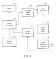
- FIG. 3illustrates an electrosurgical system incorporating a plurality of active electrodes and associated current limiting elements
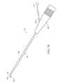
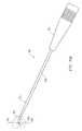
- FIG. 4is a side view of an electrosurgical probe according to the present invention.
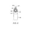
- FIG. 5is a view of the distal end portion of the probe of FIG. 2
- FIG. 6is an exploded view of a proximal portion of the electrosurgical probe
- FIGS. 7A and 7Bare perspective and end views, respectively, of an alternative electrosurgical probe incorporating an inner fluid lumen
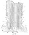
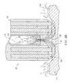
- FIGS. 8A-8Care cross-sectional views of the distal portions of three different embodiments of an electrosurgical probe according to the present invention.
- FIGS. 9-13are end views of alternative embodiments of the probe of FIG. 4, incorporating aspiration electrode(s);
- FIGS. 14A-14Cillustrate an alternative embodiment incorporating a screen electrode
- FIGS. 15A-15Dillustrate four embodiments of electrosurgical probes specifically designed for treating spinal defects
- FIG. 16illustrates an electrosurgical system incorporating a dispersive return pad for monopolar and/or bipolar operations
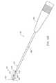
- FIG. 17illustrates a catheter system for electrosurgical treatment of intervertebral discs according to the present invention
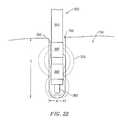
- FIGS. 18-22illustrate a method of performing a microendoscopic discectomy according to the principles of the present invention.
- FIGS. 23-25illustrates another method of treating a spinal disc with one of the catheters or probes of the present invention.
- the present inventionprovides systems and methods for selectively applying electrical energy to a target location within or on a patient's body, particularly including tissue or other body structures in the spine.
- These proceduresinclude treating degenerative discs, laminectomy/disketomy procedures for treating herniated discs, decompressive laminectomy for stenosis in the lumbosacral and cervical spine, localized tears or fissures in the annulus, nucleotomy, disc fusion procedures, medial facetectomy, posterior lumbosacral and cervical spine fusions, treatment of scoliosis associated with vertebral disease, foraminotomies to remove the roof of the intervertebral foramina to relieve nerve root compression and anterior cervical and lumbar discectomies.
- These proceduresmay be performed through open procedures, or using minimally invasive techniques, such as thoracoscopy, arthroscopy, laparascopy or the like.
- the present inventioninvolves techniques for treating disc abnormalities with RF energy.
- RF energyis used to ablate, debulk and/or stiffen the tissue structure of the disc to reduce the volume of the disc, thereby relieving neck and back pain.
- spinal disc tissueis volumetrically removed or ablated to form holes, channels, divots or other spaces within the disc.
- a high frequency voltage differenceis applied between one or more active electrode(s) and one or more return electrode(s) to develop high electric field intensities in the vicinity of the target tissue.
- the high electric field intensities adjacent the active electrode(s)lead to electric field induced molecular breakdown of target tissue through molecular dissociation (rather than thermal evaporation or carbonization).
- tissue structureis volumetrically removed through molecular disintegration of larger organic molecules into smaller molecules and/or atoms, such as hydrogen, oxygen, oxides of carbon, hydrocarbons and nitrogen compounds.
- This molecular disintegrationcompletely removes the tissue structure, as opposed to dehydrating the tissue material by the removal of liquid within the cells of the tissue, as is typically the case with electrosurgical desiccation and vaporization.
- the high electric field intensitiesmay be generated by applying a high frequency voltage that is sufficient to vaporize an electrically conducting fluid over at least a portion of the active electrode(s) in the region between the distal tip of the active electrode(s) and the target tissue.
- the electrically conductive fluidmay be a liquid or gas, such as isotonic saline, blood or intracellular fluid, delivered to, or already present at, the target site, or a viscous fluid, such as a gel, applied to the target site.
- the vapor layer or vaporized regionSince the vapor layer or vaporized region has a relatively high electrical impedance, it increases the voltage differential between the electrode terminal tip and the tissue and causes ionization within the vapor layer due to the presence of an ionizable species (e.g., sodium when isotonic saline is the electrically conducting fluid).
- This ionizationunder the conditions described herein, induces the discharge of energetic electrons and photons from the vapor layer and to the surface of the target tissue.
- This energymay be in the form of energetic photons (e.g., ultraviolet radiation), energetic particles (e.g., electrons or ions) or a combination thereof.
- CoblationTMcan be found in commonly assigned U.S. Pat. No. 5,697,882 the complete disclosure of which is incorporated herein by reference.
- Applicantbelieves that the principle mechanism of tissue removal in the CoblationTM mechanism of the present invention is energetic electrons or ions that have been energized in a plasma adjacent to the active electrode(s).
- a liquidis heated enough that atoms vaporize off the surface faster than they recondense, a gas is formed.
- the gasis heated enough that the atoms collide with each other and knock their electrons off in the process, an ionized gas or plasma is formed (the so-called “fourth state of matter”).
- a more complete description of plasmacan be found in Plasma Physics, by R. J. Goldston and P. H. Rutherford of the Plasma Physics Laboratory of Princeton University (1995).
- the electron mean free pathincreases to enable subsequently injected electrons to cause impact ionization within these regions of low density (i.e., vapor layers or bubbles).
- the ionic particles in the plasma layerhave sufficient energy, they accelerate towards the target tissue.
- Energy evolved by the energetic electronse.g., 3.5 eV to 5 eV
- Plasmasmay be formed by heating a gas and ionizing the gas by driving an electric current through it, or by shining radio waves into the gas.
- these methods of plasma formationgive energy to free electrons in the plasma directly, and then electron-atom collisions liberate more electrons, and the process cascades until the desired degree of ionization is achieved.
- the electronscarry the electrical current or absorb the radio waves and, therefore, are hotter than the ions.
- the electronswhich are carried away from the tissue towards the return electrode, carry most of the plasma's heat with them, allowing the ions to break apart the tissue molecules in a substantially non-thermal manner.
- the present inventionapplies high frequency (RF) electrical energy in an electrically conducting media environment to remove (i.e., resect, cut or ablate) a tissue structure and to seal transected vessels within the region of the target tissue.
- RFhigh frequency
- the present inventionmay also be useful for sealing larger arterial vessels, e.g., on the order of about 1 mm in diameter.
- a high frequency power supplyis provided having an ablation mode, wherein a first voltage is applied to an electrode terminal sufficient to effect molecular dissociation or disintegration of the tissue, and a coagulation mode, wherein a second, lower voltage is applied to an electrode terminal (either the same or a different electrode) sufficient to achieve hemostasis of severed vessels within the tissue.
- an electrosurgical instrumenthaving one or more coagulation electrode(s) configured for sealing a severed vessel, such as an arterial vessel, and one or more electrode terminals configured for either contracting the collagen fibers within the tissue or removing (ablating) the tissue, e.g., by applying sufficient energy to the tissue to effect molecular dissociation.
- the coagulation electrode(s)may be configured such that a single voltage can be applied to coagulate with the coagulation electrode(s), and to ablate with the electrode terminal(s).
- the power supplyis combined with the coagulation instrument such that the coagulation electrode is used when the power supply is in the coagulation mode (low voltage), and the electrode terminal(s) are used when the power supply is in the ablation mode (higher voltage).
- one or more electrode terminalsare brought into close proximity to tissue at a target site, and the power supply is activated in the ablation mode such that sufficient voltage is applied between the electrode terminals and the return electrode to volumetrically remove the tissue through molecular dissociation, as described below.
- the power supplyis activated in the ablation mode such that sufficient voltage is applied between the electrode terminals and the return electrode to volumetrically remove the tissue through molecular dissociation, as described below.
- vessels within the tissuewill be severed. Smaller vessels will be automatically sealed with the system and method of the present invention. Larger vessels, and those with a higher flow rate, such as arterial vessels, may not be automatically sealed in the ablation mode. In these cases, the severed vessels may be sealed by activating a control (e.g., a foot pedal) to reduce the voltage of the power supply into the coagulation mode.
- a controle.g., a foot pedal
- the electrode terminalsmay be pressed against the severed vessel to provide sealing and/or coagulation of the vessel.
- a coagulation electrode located on the same or a different instrumentmay be pressed against the severed vessel.
- the tissueis purposely damaged in a thermal heating mode to create necrosed or scarred tissue at the tissue surface.
- the high frequency voltage in the thermal heating modeis below the threshold of ablation as described above, but sufficient to cause some thermal damage to the tissue immediately surrounding the electrodes without vaporizing or otherwise debulking this tissue in situ.
- the voltage required for this thermal damagewill partly depend on the electrode configurations, the conductivity of the area immediately surrounding the electrodes, the time period in which the voltage is applied and the depth of tissue damage desired.
- the voltage level for thermal heatingwill usually be in the range of about 20 to 300 volts rms, preferably about 60 to 200 volts rms.
- the peak-to-peak voltages for thermal heating with a square wave form having a crest factor of about 2are typically in the range of about 40 to 600 volts peak-to-peak, preferably about 120 to 400 volts peak-to-peak. The higher the voltage is within this range, the less time required. If the voltage is too high, however, the surface tissue may be vaporized, debulked or ablated, which is undesirable.
- the present inventionmay be used for treating degenerative discs with fissures or tears.
- the active and return electrode(s)are positioned in or around the inner wall of the disc annulus such that the active electrode is adjacent to the fissure.
- High frequency voltageis applied between the active and return electrodes to heat the fissure and shrink the collagen fibers and create a seal or weld within the inner wall, thereby helping to close the fissure in the annulus.
- the return electrodewill typically be positioned proximally from the active electrode(s) on the instrument shaft, and an electrically conductive fluid will be applied to the target site to create the necessary current path between the active and return electrodes.
- the disc tissuemay complete this electrically conductive path.
- the present inventionis also useful for removing or ablating tissue around nerves, such as spinal, peripheral or cranial nerves.
- nervessuch as spinal, peripheral or cranial nerves.
- One of the significant drawbacks with the prior art shavers or microdebriders, conventional electrosurgical devices and lasersis that these devices do not differentiate between the target tissue and the surrounding nerves or bone. Therefore, the surgeon must be extremely careful during these procedures to avoid damage to the bone or nerves within and around the target site.
- the CoblationTM process for removing tissueresults in extremely small depths of collateral tissue damage as discussed above. This allows the surgeon to remove tissue close to a nerve without causing collateral damage to the nerve fibers.
- Nervesusually comprise a connective tissue sheath, or epineurium, enclosing the bundles of nerve fibers, each bundle being surrounded by its own sheath of connective tissue (the perineurium) to protect these nerve fibers.
- the outer protective tissue sheath or epineuriumtypically comprises a fatty tissue (e.g., adipose tissue) having substantially different electrical properties than the normal target tissue, such as the turbinates, polyps, mucus tissue or the like, that are, for example, removed from the nose during sinus procedures.
- the system of the present inventionmeasures the electrical properties of the tissue at the tip of the probe with one or more electrode terminal(s). These electrical properties may include electrical conductivity at one, several or a range of frequencies (e.g., in the range from 1 kHz to 100 MHz), dielectric constant, capacitance or combinations of these.
- an audible signalmay be produced when the sensing electrode(s) at the tip of the probe detects the fatty tissue surrounding a nerve, or direct feedback control can be provided to only supply power to the electrode terminal(s) either individually or to the complete array of electrodes, if and when the tissue encountered at the tip or working end of the probe is normal tissue based on the measured electrical properties.
- the current limiting elementsare configured such that the electrode terminals will shut down or turn off when the electrical impedance reaches a threshold level.
- a threshold levelis set to the impedance of the fatty tissue surrounding nerves, the electrode terminals will shut off whenever they come in contact with, or in close proximity to, nerves. Meanwhile, the other electrode terminals, which are in contact with or in close proximity to tissue, will continue to conduct electric current to the return electrode.
- the present inventionis capable of volumetrically removing tissue closely adjacent to nerves without impairment the function of the nerves, and without significantly damaging the tissue of the epineurium.
- One of the significant drawbacks with the prior art microdebriders, conventional electrosurgical devices and lasersis that these devices do not differentiate between the target tissue and the surrounding nerves or bone. Therefore, the surgeon must be extremely careful during these procedures to avoid damage to the bone or nerves within and around the nasal cavity.
- the CoblationTM process for removing tissueresults in extremely small depths of collateral tissue damage as discussed above. This allows the surgeon to remove tissue close to a nerve without causing collateral damage to the nerve fibers.
- the CoblationTM mechanism of the present inventioncan be manipulated to ablate or remove certain tissue structures, while having little effect on other tissue structures.
- the present inventionuses a technique of vaporizing electrically conductive fluid to form a plasma layer or pocket around the electrode terminal(s), and then inducing the discharge of energy from this plasma or vapor layer to break the molecular bonds of the tissue structure. Based on initial experiments, applicants believe that the free electrons within the ionized vapor layer are accelerated in the high electric fields near the electrode tip(s).
- the electron mean free pathincreases to enable subsequently injected electrons to cause impact ionization within these regions of low density (i.e., vapor layers or bubbles).
- Energy evolved by the energetic electronse.g., 4 to 5 eV
- the energy evolved by the energetic electronsmay be varied by adjusting a variety of factors, such as: the number of electrode terminals; electrode size and spacing; electrode surface area; asperities and sharp edges on the electrode surfaces; electrode materials; applied voltage and power; current limiting means, such as inductors; electrical conductivity of the fluid in contact with the electrodes; density of the fluid; and other factors. Accordingly, these factors can be manipulated to control the energy level of the excited electrons. Since different tissue structures have different molecular bonds, the present invention can be configured to break the molecular bonds of certain tissue, while having too low an energy to break the molecular bonds of other tissue.
- fatty tissuee.g., adipose
- fatty tissuee.g., adipose
- the present invention in its cur configurationgenerally does not ablate or remove such fatty tissue.
- factorsmay be changed such that these double bonds can also be broken in a similar fashion as the single bonds (e.g., increasing voltage or changing the electrode configuration to increase the current density at the electrode tips).
- a more complete description of this phenomenacan be found in co-pending U.S. patent application Ser. No. 09/032,375, filed Feb. 27, 1998, the complete disclosure of which is incorporated herein by reference.
- the present inventionalso provides systems, apparatus and methods for selectively removing tumors, e.g., facial tumors, or other undesirable body structures while minimizing the spread of viable cells from the tumor.
- Conventional techniques for removing such tumorsgenerally result in the production of smoke in the surgical setting, termed an electrosurgical or laser plume, which can spread intact, viable bacterial or viral particles from the tumor or lesion to the surgical team or to other portions of the patient's body.
- This potential spread of viable cells or particleshas resulted in increased concerns over the proliferation of certain debilitating and fatal diseases, such as hepatitis, herpes, HIV and papillomavirus.
- high frequency voltageis applied between the electrode terminal(s) and one or more return electrode(s) to volumetrically remove at least a portion of the tissue cells in the tumor through the dissociation or disintegration of organic molecules into non-viable atoms and molecules.
- the present inventionconverts the solid tissue cells into non-condensable gases that are no longer intact or viable, and thus, not capable of spreading viable tumor particles to other portions of the patient's brain or to the surgical staff.
- the high frequency voltageis preferably selected to effect controlled removal of these tissue cells while minimizing substantial tissue necrosis to surrounding or underlying tissue.
- the RF energyheats the disc tissue directly by virtue of the electrical current flow therethrough, and/or indirectly through the exposure of the tissue to fluid heated by RF energy, to elevate the tissue temperature from normal body temperatures (e.g., 37° C.) to temperatures in the range of 45° C. to 90° C., preferably in the range from about 60° C. to 70° C.
- Thermal shrinkage of collagen fibersoccurs within a small temperature range which, for mammalian collagen is in the range from 60° C. to 70° C.
- the preferred depth of heating to effect the shrinkage of collagen in the heated regioni.e. the depth to which the tissue is elevated to temperatures between 60° C. to 70° C.
- the depth of heatingis usually in the range from 1.0 to 5.0 mm.
- the electrosurgical probe or catheterwill comprise a shaft or a handpiece having a proximal end and a distal end which supports one or more electrode terminal(s).
- the shaft or handpiecemay assume a wide variety of configurations, with the primary purpose being to mechanically support the active electrode and permit the treating physician to manipulate the electrode from a proximal end of the shaft.
- the shaftmay be rigid or flexible, with flexible shafts optionally being combined with a generally rigid external tube for mechanical support. Flexible shafts may be combined with pull wires, shape memory actuators, and other known mechanisms for effecting selective deflection of the distal end of the shaft to facilitate positioning of the electrode array.
- the shaftwill usually include a plurality of wires or other conductive elements running axially therethrough to permit connection of the electrode array to a connector at the proximal end of the shaft.
- the shaftwill have a suitable diameter and length to allow the surgeon to reach the target site (e.g., a disc) by delivering the shaft through the thoracic cavity, the abdomen or the like.
- the shaftwill usually have a length in the range of about 5.0 to 30.0 cm, and a diameter in the range of about 0.2 mm to about 20 mm.
- the shaftmay be delivered directly through the patient's back in a posterior approach, which would considerably reduce the required length of the shaft.
- the shaftmay also be introduced through rigid or flexible endoscopes.
- the shaftmay be a flexible catheter that is introduced through a percutaneous penetration in the patient. Specific shaft designs will be described in detail in connection with the figures hereinafter.
- the probemay comprise a long, thin needle (e.g., on the order of about 1 mm in diameter or less) that can be percutaneously introduced through the patient's back directly into the spine.
- the needlewill include one or more active electrode(s) for applying electrical energy to tissues within the spine.
- the needlemay include one or more return electrode(s), or the return electrode may be positioned on the patient's back, as a dispersive pad. In either embodiment, sufficient electrical energy is applied through the needle to the active electrode(s) to either shrink the collagen fibers within the spinal disc, or to ablate tissue within the disc.
- the electrosurgical instrumentmay also be a catheter that is delivered percutaneously and/or endoluminally into the patient by insertion through a conventional or specialized guide catheter, or the invention may include a catheter having an active electrode or electrode array integral with its distal end.
- the catheter shaftmay be rigid or flexible, with flexible shafts optionally being combined with a generally rigid external tube for mechanical support. Flexible shafts may be combined with pull wires, shape memory actuators, and other known mechanisms for effecting selective deflection of the distal end of the shaft to facilitate positioning of the electrode or electrode array.
- the catheter shaftwill usually include a plurality of wires or other conductive elements running axially therethrough to permit connection of the electrode or electrode array and the return electrode to a connector at the proximal end of the catheter shaft.
- the catheter shaftmay include a guide wire for guiding the catheter to the target site, or the catheter may comprise a steerable guide catheter.
- the cathetermay also include a substantially rigid distal end portion to increase the torque control of the distal end portion as the catheter is advanced further into the patient's body.
- the electrode terminal(s)are preferably supported within or by an inorganic insulating support positioned near the distal end of the instrument shaft.
- the return electrodemay be located on the instrument shaft, on another instrument or on the external surface of the patient (i.e., a dispersive pad).
- a dispersive padlocated on the instrument shaft, on another instrument or on the external surface of the patient (i.e., a dispersive pad).
- the return electrodeis preferably either integrated with the instrument body, or another instrument located in close proximity thereto.
- the proximal end of the instrument(s)will include the appropriate electrical connections for coupling the return electrode(s) and the electrode terminal(s) to a high frequency power supply, such as an electrosurgical generator.
- the active electrode(s)have an active portion or surface with surface geometries shaped to promote the electric field intensity and associated current density along the leading edges of the electrodes. Suitable surface geometries may be obtained by creating electrode shapes that include preferential sharp edges, or by creating asperities or other surface roughness on the active surface(s) of the electrodes. Electrode shapes according to the present invention can include the use of formed wire (e.g., by drawing round wire through a shaping die) to form electrodes with a variety of cross-sectional shapes, such as square, rectangular, L or V shaped, or the like. Electrode edges may also be created by removing a portion of the elongate metal electrode to reshape the cross-section.
- materialcan be ground along the length of a round or hollow wire electrode to form D or C shaped wires, respectively, with edges facing in the cutting direction.
- materialcan be removed at closely spaced intervals along the electrode length to form transverse grooves, slots, threads or the like along the electrodes.
- the active electrode surface(s)may be modified through chemical, electrochemical or abrasive methods to create a multiplicity of surface asperities on the electrode surface. These surface asperities will promote high electric field intensities between the active electrode surface(s) and the target tissue to facilitate ablation or cutting of the tissue.
- surface asperitiesmay be created by etching the active electrodes with etchants having a Ph less than 7.0 or by using a high velocity stream of abrasive particles (e.g., grit blasting) to create asperities on the surface of an elongated electrode.
- abrasive particlese.g., grit blasting
- the return electrodeis typically spaced proximally from the active electrode(s) a suitable distance to avoid electrical shorting between the active and return electrodes in the presence of electrically conductive fluid.
- the distal edge of the exposed surface of the return electrodeis spaced about 0.5 to 25 mm from the proximal edge of the exposed surface of the active electrode(s), preferably about 1.0 to 5.0 mm.
- this distancemay vary with different voltage ranges, conductive fluids, and depending on the proximity of tissue structures to active and return electrodes.
- the return electrodewill typically have an exposed length in the range of about 1 to 20 mm.
- the current flow path between the electrode terminals and the return electrode(s)may be generated by submerging the tissue site in an electrical conducting fluid (e.g., within a viscous fluid, such as an electrically conductive gel) or by directing an electrically conducting fluid along a fluid path to the target site (i.e., a liquid, such as isotonic saline, hypotonic saline or a gas, such as argon).
- the conductive gelmay also be delivered to the target site to achieve a slower more controlled delivery rate of conductive fluid.
- the viscous nature of the gelmay allow the surgeon to more easily contain the gel around the target site (e.g., rather than attempting to contain isotonic saline).
- a liquid electrically conductive fluide.g., isotonic saline
- a liquid electrically conductive fluidmay be used to concurrently “bathe” the target tissue surface to provide an additional means for removing any tissue, and to cool the region of the target tissue ablated in the previous moment.
- the power supplymay include a fluid interlock for interrupting power to the electrode terminal(s) when there is insufficient conductive fluid around the electrode terminal(s). This ensures that the instrument will not be activated when conductive fluid is not present, minimizing the tissue damage that may otherwise occur.
- a fluid interlockcan be found in commonly assigned, co-pending U.S. application Ser. No. 09/058,336, filed Apr. 10, 1998, the complete disclosure of which is incorporated herein by reference.
- the system of the present inventionmay include one or more suction lumen(s) in the instrument, or on another instrument, coupled to a suitable vacuum source for aspirating fluids from the target site.
- the inventionmay include one or more aspiration electrode(s) coupled to the distal end of the suction lumen for ablating, or at least reducing the volume of, non-ablated tissue fragments that are aspirated into the lumen.
- the aspiration electrode(s)function mainly to inhibit clogging of the lumen that may otherwise occur as larger tissue fragments are drawn therein.
- the aspiration electrode(s)may be different from the ablation electrode terminal(s), or the same electrode(s) may serve both functions.
- suctionit may be desirable to contain the excess electrically conductive fluid, tissue fragments and/or gaseous products of ablation at or near the target site with a containment apparatus, such as a basket, retractable sheath or the like.
- a containment apparatussuch as a basket, retractable sheath or the like.
- This embodimenthas the advantage of ensuring that the conductive fluid, tissue fragments or ablation products do not flow through the patient's vasculature or into other portions of the body.
- the present inventionmay use a single active electrode terminal or an array of electrode terminals spaced around the distal surface of a catheter or probe.
- the electrode arrayusually includes a plurality of independently current-limited and/or power-controlled electrode terminals to apply electrical energy selectively to the target tissue while limiting the unwanted application of electrical energy to the surrounding tissue and environment resulting from power dissipation into surrounding electrically conductive fluids, such as blood, normal saline, and the like.
- the electrode terminalsmay be independently current-limited by isolating the terminals from each other and connecting each terminal to a separate power source that is isolated from the other electrode terminals.
- the electrode terminalsmay be connected to each other at either the proximal or distal ends of the catheter to form a single wire that couples to a power source.
- each individual electrode terminal in the electrode arrayis electrically insulated from all other electrode terminals in the array within said instrument and is connected to a power source which is isolated from each of the other electrode terminals in the array or to circuitry which limits or interrupts current flow to the electrode terminal when low resistivity material (e.g., blood, electrically conductive saline irrigant or electrically conductive gel) causes a lower impedance path between the return electrode and the individual electrode terminal.
- the isolated power sources for each individual electrode terminalmay be separate power supply circuits having internal impedance characteristics which limit power to the associated electrode terminal when a low impedance return path is encountered.
- the isolated power sourcemay be a user selectable constant current source.
- a single power sourcemay be connected to each of the electrode terminals through independently actuatable switches, or by independent current limiting elements, such as inductors, capacitors, resistors and/or combinations thereof.
- the current limiting elementsmay be provided in the instrument, connectors, cable, controller or along the conductive path from the controller to the distal tip of the instrument.
- the resistance and/or capacitancemay occur on the surface of the active electrode terminal(s) due to oxide layers which form selected electrode terminals (e.g., titanium or a resistive coating on the surface of metal, such as platinum).
- the tip region of the instrumentmay comprise many independent electrode terminals designed to deliver electrical energy in the vicinity of the tip.
- the selective application of electrical energy to the conductive fluidis achieved by connecting each individual electrode terminal and the return electrode to a power source having independently controlled or current limited channels.
- the return electrode(s)may comprise a single tubular member of conductive material proximal to the electrode array at the tip which also serves as a conduit for the supply of the electrically conducting fluid between the active and return electrodes.
- the instrumentmay comprise an array of return electrodes at the distal tip of the instrument (together with the active electrodes) to maintain the electric current at the tip.
- the application of high frequency voltage between the return electrode(s) and the electrode arrayresults in the generation of high electric field intensities at the distal tips of the electrode terminals with conduction of high frequency current from each individual electrode terminal to the return electrode.
- the current flow from each individual electrode terminal to the return electrode(s)is controlled by either active or passive means, or a combination thereof, to deliver electrical energy to the surrounding conductive fluid while minimizing energy delivery to surrounding (non-target) tissue.
- the tissue volume over which energy is dissipated(i.e., a high current density exists) may be more precisely controlled, for example, by the use of a multiplicity of small electrode terminals whose effective diameters or principal dimensions range from about 10 mm to 0.01 mm, preferably from about 2 mm to 0.05 mm, and more preferably from about 1 mm to 0.1 mm.
- electrode areas for both circular and non-circular terminalswill have a contact area (per electrode terminal) below 50 mm2 for electrode arrays and as large as 75 mm2 for single electrode embodiments.
- the contact area of each electrode terminalis typically in the range from 0.0001 mm2 to 1 mm2, and more preferably from 0.001 mm2 to 0.5 mm2.
- the circumscribed area of the electrode array or electrode terminalis in the range from 0.25 mm2 to 75 mm2, preferably from 0.5 mm2 to 40 mm2.
- the arraywill usually include at least two isolated electrode terminals, often at least five electrode terminals, often greater than 10 electrode terminals and even 50 or more electrode terminals, disposed over the distal contact surfaces on the shaft. The use of small diameter electrode terminals increases the electric field intensity and reduces the extent or depth of tissue heating as a consequence of the divergence of current flux lines which emanate from the exposed surface of each electrode terminal.
- the area of the tissue treatment surfacecan vary widely, and the tissue treatment surface can assume a variety of geometries, with particular areas and geometries being selected for specific applications.
- the geometriescan be planar, concave, convex, hemispherical, conical, linear “in-line” array or virtually any other regular or irregular shape.
- the active electrode(s) or electrode terminal(s)will be formed at the distal tip of the electrosurgical instrument shaft, frequently being planar, disk-shaped, or hemispherical surfaces for use in reshaping procedures or being linear arrays for use in cutting.
- the active electrode(s)may be formed on lateral surfaces of the electrosurgical instrument shaft (e.g., in the manner of a spatula), facilitating access to certain body structures in endoscopic procedures.
- the electrode support and the fluid outletmay be recessed from an outer surface of the instrument or handpiece to confine the electrically conductive fluid to the region immediately surrounding the electrode support.
- the shaftmay be shaped so as to form a cavity around the electrode support and the fluid outlet. This helps to assure that the electrically conductive fluid will remain in contact with the electrode terminal(s) and the return electrode(s) to maintain the conductive path therebetween. In addition, this will help to maintain a vapor layer and subsequent plasma layer between the electrode terminal(s) and the tissue at the treatment site throughout the procedure, which reduces the thermal damage that might otherwise occur if the vapor layer were extinguished due to a lack of conductive fluid. Provision of the electrically conductive fluid around the target site also helps to maintain the tissue temperature at desired levels.
- the active electrodesare spaced from the tissue a sufficient distance to minimize or avoid contact between the tissue and the vapor layer formed around the active electrodes.
- contact between the heated electrons in the vapor layer and the tissueis minimized as these electrons travel from the vapor layer back through the conductive fluid to the return electrode.
- the ions within the plasmawill have sufficient energy, under certain conditions such as higher voltage levels, to accelerate beyond the vapor layer to the tissue.
- the tissue bondsare dissociated or broken as in previous embodiments, while minimizing the electron flow, and thus the thermal energy, in contact with the tissue.
- the electrically conducting fluidshould have a threshold conductivity to provide a suitable conductive path between the return electrode and the electrode terminal(s).
- the electrical conductivity of the fluid(in units of milliSiemans per centimeter or mS/cm) will usually be greater than 0.2 mS/cm, preferably will be greater than 2 mS/cm and more preferably greater than 10 mS/cm.
- the electrically conductive fluidis isotonic saline, which has a conductivity of about 17 mS/cm. Applicant has found that a more conductive fluid, or one with a higher ionic concentration, will usually provide a more aggressive ablation rate.
- a saline solution with higher levels of sodium chloride than conventional saline(which is on the order of about 0.9% sodium chloride) e.g., on the order of greater than 1% or between about 3% and 20%, may be desirable.
- the inventionmay be used with different types of conductive fluids that increase the power of the plasma layer by, for example, increasing the quantity of ions in the plasma, or by providing ions that have higher energy levels than sodium ions.
- the present inventionmay be used with elements other than sodium, such as potassium, magnesium, calcium and other metals near the left end of the periodic chart.
- other electronegative elementsmay be used in place of chlorine, such as fluorine.
- the voltage difference applied between the return electrode(s) and the electrode terminal(s)will be at high or radio frequency, typically between about 5 kHz and 20 MHz, usually being between about 30 kHz and 2.5 MHz, preferably being between about 50 kHz and 500 kHz, often less than 350 kHz, and often between about 100 kHz and 200 kHz.
- a frequency of about 100 kHzis useful because the tissue impedance is much greater at this frequency.
- higher frequenciesmay be desirable (e.g., 400-600 kHz) to minimize low frequency current flow into the heart or the nerves of the head and neck.
- the RMS (root mean square) voltage appliedwill usually be in the range from about 5 volts to 1000 volts, preferably being in the range from about 10 volts to 500 volts, often between about 150 to 400 volts depending on the electrode terminal size, the operating frequency and the operation mode of the particular procedure or desired effect on the tissue (i.e., contraction, coagulation, cutting or ablation).
- the peak-to-peak voltage for ablation or cutting with a square wave formwill be in the range of 10 to 2000 volts and preferably in the range of 100 to 1800 volts and more preferably in the range of about 300 to 1500 volts, often in the range of about 300 to 800 volts peak to peak (again, depending on the electrode size, number of electrons, the operating frequency and the operation mode).
- Lower peak-to-peak voltageswill be used for tissue coagulation, thermal heating of tissue, or collagen contraction and will typically be in the range from 50 to 1500, preferably 100 to 1000 and more preferably 120 to 400 volts peak-to-peak (again, these values are computed using a square wave form).
- Peak-to-peak voltagese.g., greater than about 800 volts peak-to-peak, may be desirable for ablation of harder material, such as bone, depending on other factors, such as the electrode geometries and the composition of the conductive fluid.
- the voltageis usually delivered in a series of voltage pulses or alternating current of time varying voltage amplitude with a sufficiently high frequency (e.g., on the order of 5 kHz to 20 MHz) such that the voltage is effectively applied continuously (as compared with e.g., lasers claiming small depths of necrosis, which are generally pulsed about 10 to 20 Hz).
- the duty cyclei.e., cumulative time in any one-second interval that energy is applied
- the preferred power source of the present inventiondelivers a high frequency current selectable to generate average power levels ranging from several milliwatts to tens of watts per electrode, depending on the volume of target tissue being heated, and/or the maximum allowed temperature selected for the instrument tip.
- the power sourceallows the user to select the voltage level according to the specific requirements of a particular neurosurgery procedure, cardiac surgery, arthroscopic surgery, dermatological procedure, ophthalmic procedures, open surgery or other endoscopic surgery procedure.
- the power sourcemay have an additional filter, for filtering leakage voltages at frequencies below 100 kHz, particularly voltages around 60 kHz.
- a power source having a higher operating frequencye.g., 300 to 600 kHz may be used in certain procedures in which stray low frequency currents may be problematic.
- a description of one suitable power sourcecan be found in co-pending patent applications Ser. Nos. 09/058,571 and 09/058,336, filed Apr. 10, 1998, the complete disclosure of both applications are incorporated herein by reference for all purposes.
- the power sourcemay be current limited or otherwise controlled so that undesired heating of the target tissue or surrounding (non-target) tissue does not occur.
- current limiting inductorsare placed in series with each independent electrode terminal, where the inductance of the inductor is in the range of 10 uH to 50,000 uH, depending on the electrical properties of the target tissue, the desired tissue heating rate and the operating frequency.
- capacitor-inductor (LC) circuit structuresmay be employed, as described previously in U.S. Pat. No. 5,697,909, the complete disclosure of which is incorporated herein by reference. Additionally, current limiting resistors may be selected.
- these resistorswill have a large positive temperature coefficient of resistance so that, as the current level begins to rise for any individual electrode terminal in contact with a low resistance medium (e.g., saline irrigant or blood), the resistance of the current limiting resistor increases significantly, thereby minimizing the power delivery from said electrode terminal into the low resistance medium (e.g., saline irrigant or blood).
- a low resistance mediume.g., saline irrigant or blood
- the inventionis not limited to electrically isolated electrode terminals, or even to a plurality of electrode terminals.
- the array of active electrode terminalsmay be connected to a single lead that extends through the catheter shaft to a power source of high frequency current.
- the instrumentmay incorporate a single electrode that extends directly through the catheter shaft or is connected to a single lead that extends to the power source.
- the active electrode(s)may have ball shapes (e.g., for tissue vaporization and desiccation), twizzle shapes (for vaporization and needle-like cutting), spring shapes (for rapid tissue debulking and desiccation), twisted metal shapes, annular or solid tube shapes or the like.
- the electrode(s)may comprise a plurality of filaments, rigid or flexible brush electrode(s) (for debulking a tumor, such as a fibroid, bladder tumor or a prostate adenoma), side-effect brush electrode(s) on a lateral surface of the shaft, coiled electrode(s) or the like.
- Electrosurgical system 11generally comprises an electrosurgical handpiece or probe 10 connected to a power supply 28 for providing high frequency voltage to a target site and a fluid source 21 for supplying electrically conducting fluid 50 to probe 10 .
- electrosurgical system 11may include an endoscope (not shown) with a fiber optic head light for viewing the surgical site.
- the endoscopemay be integral with probe 10 , or it may be part of a separate instrument.
- the system 11may also include a vacuum source (not shown) for coupling to a suction lumen or tube 205 (see FIG. 2) in the probe 10 for aspirating the target site.
- probe 10generally includes a proximal handle 19 and an elongate shaft 18 having an array 12 of electrode terminals 58 at its distal end.
- a connecting cable 34has a connector 26 for electrically coupling the electrode terminals 58 to power supply 28 .
- the electrode terminals 58are electrically isolated from each other and each of the terminals 58 is connected to an active or passive control network within power supply 28 by means of a plurality of individually insulated conductors (not shown).
- a fluid supply tube 15is connected to a fluid tube 14 of probe 10 for supplying electrically conducting fluid 50 to the target site. Fluid supply tube 15 may be connected to a suitable pump (not shown), if desired.
- Power supply 28has an operator controllable voltage level adjustment 30 to change the applied voltage level, which is observable at a voltage level display 32 .
- Power supply 28also includes first, second and third foot pedals 37 , 38 , 39 and a cable 36 which is removably coupled to power supply 28 .
- the foot pedals 37 , 38 , 39allow the surgeon to remotely adjust the energy level applied to electrode terminals 58 .
- first foot pedal 37is used to place the power supply into the “ablation” mode and second foot pedal 38 places power supply 28 into the “sub-ablation” mode (e.g., coagulation or contraction of tissue).
- the third foot pedal 39allows the user to adjust the voltage level within the “ablation” mode.
- a sufficient voltageis applied to the electrode terminals to establish the requisite conditions for molecular dissociation of the tissue (i.e., vaporizing a portion of the electrically conductive fluid, ionizing charged particles within the vapor layer and accelerating these charged particles against the tissue).
- the requisite voltage level for ablationwill vary depending on the number, size, shape and spacing of the electrodes, the distance in which the electrodes extend from the support member, etc.
- the power supply 28applies a low enough voltage to the electrode terminals to avoid vaporization of the electrically conductive fluid and subsequent molecular dissociation of the tissue.
- the surgeonmay automatically toggle the power supply between the ablation and sub-ablation modes by alternatively stepping on foot pedals 37 , 38 , respectively. In some embodiments, this allows the surgeon to quickly move between coagulation/thermal heating and ablation in situ, without having to remove his/her concentration from the surgical field or without having to request an assistant to switch the power supply.
- the probetypically will simultaneously seal and/or coagulation small severed vessels within the tissue.
- the surgeoncan simply step on foot pedal 38 , automatically lowering the voltage level below the threshold level for ablation, and apply sufficient pressure onto the severed vessel for a sufficient period of time to seal and/or coagulate the vessel. After this is completed, the surgeon may quickly move back into the ablation mode by stepping on foot pedal 37 .
- the high frequency power supply of the present inventionis configured to apply a high frequency voltage of about 10 to 500 volts RMS between one or more electrode terminals (and/or coagulation electrode) and one or more return electrodes.
- the power supplyapplies about 70-350 volts RMS in the ablation mode and about 20 to 90 volts in a subablation mode, preferably 45 to 70 volts in the subablation mode (these values will, of course, vary depending on the probe configuration attached to the power supply and the desired mode of operation).
- the preferred power source of the present inventiondelivers a high frequency current selectable to generate average power levels ranging from several milliwatts to tens of watts per electrode, depending on the volume of target tissue being heated, and/or the maximum allowed temperature selected for the probe tip.
- the power sourceallows the user to select the voltage level according to the specific requirements of a particular procedure, e.g., arthroscopic surgery, dermatological procedure, ophthalmic procedures, open surgery or other endoscopic surgery procedure.
- the power supplygenerally comprises a radio frequency (RF) power oscillator 100 having output connections for coupling via a power output signal 102 to the load impedance, which is represented by the electrode assembly when the electrosurgical probe is in use.
- RFradio frequency
- the RF oscillatoroperates at about 100 kHz.
- the RF oscillatoris not limited to this frequency and may operate at frequencies of about 300 kHz to 600 kHz. In particular, for cardiac applications, the RF oscillator will preferably operate in the range of about 400 kHz to about 600 kHz.
- the RF oscillatorwill generally supply a square wave signal with a crest factor of about 1 to 2.
- this signalmay be a sine wave signal or other suitable wave signal depending on the application and other factors, such as the voltage applied, the number and geometry of the electrodes, etc.
- the power output signal 102is designed to incur minimal voltage decrease (i.e., sag) under load. This improves the applied voltage to the electrode terminals and the return electrode, which improves the rate of volumetric removal (ablation) of tissue.
- the switching power supply 140allows the generator to achieve high peak power output without the large size and weight of a bulky transformer.
- the architecture of the switching power supplyalso has been designed to reduce electromagnetic noise such that U.S. and foreign EMI requirements are met. This architecture comprises a zero voltage switching or crossing, which causes the transistors to turn ON and OFF when the voltage is zero. Therefore, the electromagnetic noise produced by the transistors switching is vastly reduced.
- the switching power supply 104operates at about 100 kHz.
- the controller 106may be a microprocessor or an integrated circuit.
- the power supplymay also include one or more current sensors 112 for detecting the output current.
- the power supplyis preferably housed within a metal casing which provides a durable enclosure for the electrical components therein.
- the metal casingreduces the electromagnetic noise generated within the power supply because the grounded metal casing functions as a “Faraday shield”, thereby shielding the environment from internal sources of electromagnetic noise.
- the power supplygenerally comprises a main or mother board containing generic electrical components required for many different surgical procedures (e.g., arthroscopy, urology, general surgery, dermatology, neurosurgery, etc.), and a daughter board containing application specific current-limiting circuitry (e.g., inductors, resistors, capacitors and the like).
- the daughter boardis coupled to the mother board by a detachable multi-pin connector to allow convenient conversion of the power supply to, e.g., applications requiring a different current limiting circuit design.
- the daughter boardpreferably comprises a plurality of inductors of about 200 to 400 microhenries, usually about 300 microhenries, for each of the channels supplying current to the electrode terminals 02 (see FIG. 2 ).
- current limiting inductorsare placed in series with each independent electrode terminal, where the inductance of the inductor is in the range of 10 uH to 50,000 uH, depending on the electrical properties of the target tissue, the desired tissue heating rate and the operating frequency.
- capacitor-inductor (LC) circuit structuresmay be employed, as described previously in co-pending PCT application No. PCT/US94/05168, the complete disclosure of which is incorporated herein by reference. Additionally, current limiting resistors may be selected.
- these resistorswill have a large positive temperature coefficient of resistance so that, as the current level begins to rise for any individual electrode terminal in contact with a low resistance medium (e.g., saline irrigant or conductive gel), the resistance of the current limiting resistor increases significantly, thereby minimizing the power delivery from said electrode terminal into the low resistance medium (e.g., saline irrigant or conductive gel).
- Power output signalmay also be coupled to a plurality of current limiting elements 96 , which are preferably located on the daughter board since the current limiting elements may vary depending on the application.
- FIGS. 4-6illustrate an exemplary electrosurgical probe 20 constructed according to the principles of the present invention.
- probe 90generally includes an elongated shaft 100 which may be flexible or rigid, a handle 204 coupled to the proximal end of shaft 100 and an electrode support member 102 coupled to the distal end of shaft 100 .
- Shaft 100preferably comprises an electrically conducting material, usually metal, which is selected from the group comprising tungsten, stainless steel alloys, platinum or its alloys, titanium or its alloys, molybdenum or its alloys, and nickel or its alloys.
- shaft 100includes an electrically insulating jacket 108 , which is typically formed as one or more electrically insulating sheaths or coatings, such as polytetrafluoroethylene, polyimide, and the like.
- electrically insulating jacket 108is typically formed as one or more electrically insulating sheaths or coatings, such as polytetrafluoroethylene, polyimide, and the like.
- the provision of the electrically insulating jacket over the shaftprevents direct electrical contact between these metal elements and any adjacent body structure or the surgeon.
- Such direct electrical contact between a body structure (e.g., tendon) and an exposed electrodecould result in unwanted heating and necrosis of the structure at the point of contact causing necrosis.
- the return electrodemay comprise an annular band coupled to an insulating shaft and having a connector extending within the shaft to its proximal end.
- Handle 204typically comprises a plastic material that is easily molded into a suitable shape for handling by the surgeon. Handle 204 defines an inner cavity (not shown) that houses the electrical connections 250 (FIG. 6 ), and provides a suitable interface for connection to an electrical connecting cable 22 (see FIG. 1 ). Electrode support member 102 extends from the distal end of shaft 100 (usually about 1 to 20 mm), and provides support for a plurality of electrically isolated electrode terminals 104 (see FIG. 5 ). As shown in FIG. 4, a fluid tube 233 extends through an opening in handle 204 , and includes a connector 235 for connection to a fluid supply source, for supplying electrically conductive fluid to the target site.
- fluid tube 233may extend through a single lumen (not shown) in shaft 100 , or it may be coupled to a plurality of lumens (also not shown) that extend through shaft 100 to a plurality of openings at its distal end.
- fluid tube 239is a plastic tubing that extends along the exterior of shaft 100 to a point just distal of return electrode 112 (see FIG. 5 ).
- the fluidis directed through an opening 237 past return electrode 112 to the electrode terminals 104 .
- Probe 20may also include a valve 17 (FIG. 1) or equivalent structure for controlling the flow rate of the electrically conducting fluid to the target site.
- Electrode support member 102has a substantially planar tissue treatment surface 212 (FIG. 5) that is usually at an angle of about 10 to 90 degrees relative to the longitudinal axis of shaft 100 , preferably about 30 to 60 degrees and more preferably about 45 degrees.
- the distal portion of shaft 100comprises a flexible material which can be deflected relative to the longitudinal axis of the shaft. Such deflection may be selectively induced by mechanical tension of a pull wire, for example, or by a shape memory wire that expands or contracts by externally applied temperature changes. A more complete description of this embodiment can be found in U.S. Pat. No. 5,697,909, the complete disclosure of which has previously been incorporated herein by reference.
- the shaft 100 of the present inventionmay be bent by the physician to the appropriate angle using a conventional bending tool or the like.
- probe 20includes a return electrode 112 for completing the current path between electrode terminals 104 and a high frequency power supply 28 (see FIG. 1 ).
- return electrode 112preferably comprises an exposed portion of shaft 100 shaped as an annular conductive band near the distal end of shaft 100 slightly proximal to tissue treatment surface 212 of electrode support member 102 , typically about 0.5 to 10 mm and more preferably about 1 to 10 mm.
- Return electrode 112 or shaft 100is coupled to a connector 258 that extends to the proximal end of probe 10 , where it is suitably connected to power supply 10 (FIG. 1 ).
- return electrode 112is not directly connected to electrode terminals 104 .
- electrically conducting fluide.g., isotonic saline
- the electrically conducting fluidis delivered through fluid tube 233 to opening 237 , as described above.
- the fluidmay be delivered by a fluid delivery element (not shown) that is separate from probe 20 .
- the body cavitywill be flooded with isotonic saline and the probe 90 will be introduced into this flooded cavity.
- Electrode conducting fluidwill be continually resupplied to maintain the conduction path between return electrode 112 and electrode terminals 104 .
- the distal portion of probe 20may be dipped into a source of electrically conductive fluid, such as a gel or isotonic saline, prior to positioning at the target site.
- a source of electrically conductive fluidsuch as a gel or isotonic saline
- the surface tension of the fluid and/or the viscous nature of a gelallows the conductive fluid to remain around the active and return electrodes for long enough to complete its function according to the present invention, as described below.
- the conductive fluidsuch as a gel, may be applied directly to the target site.
- the fluid pathmay be formed in probe 90 by, for example, an inner lumen or an annular gap between the return electrode and a tubular support member within shaft 100 (see FIGS. 8 A and 8 B).
- This annular gapmay be formed near the perimeter of the shaft 100 such that the electrically conducting fluid tends to flow radially inward towards the target site, or it may be formed towards the center of shaft 100 so that the fluid flows radially outward.
- a fluid sourcee.g., a bag of fluid elevated above the surgical site or having a pumping device
- a fluid supply tubenot shown
- a more complete description of an electrosurgical probe incorporating one or more fluid lumen(s)can be found in U.S. Pat. No. 5,697,281, the complete disclosure of which has previously been incorporated herein by reference.
- the electrically isolated electrode terminals 104are spaced apart over tissue treatment surface 212 of electrode support member 102 .
- the tissue treatment surface and individual electrode terminals 104will usually have dimensions within the ranges set forth above.
- the tissue treatment surface 212has a circular cross-sectional shape with a diameter in the range of 1 mm to 20.
- the individual electrode terminals 104preferably extend outward from tissue treatment surface 212 by a distance of about 0.1 to 4 mm, usually about 0.2 to 2 mm. Applicant has found that this configuration increases the high electric field intensities and associated current densities around electrode terminals 104 to facilitate the ablation of tissue as described in detail above.
- the probeincludes a single, larger opening 209 in the center of tissue treatment surface 212 , and a plurality of electrode terminals (e.g., about 3-15) around the perimeter of surface 212 (see FIG. 5 ).
- the probemay include a single, annular, or partially annular, electrode terminal at the perimeter of the tissue treatment surface.
- the central opening 209is coupled to a suction lumen (not shown) within shaft 100 and a suction tube 211 (FIG. 4) for aspirating tissue, fluids and/or gases from the target site.
- the electrically conductive fluidgenerally flows radially inward past electrode terminals 104 and then back through the opening 209 . Aspirating the electrically conductive fluid during surgery allows the surgeon to see the target site, and it prevents the fluid from flowing into the patient's body.
- the distal tip of probemay have a variety of different configurations.
- the probemay include a plurality of openings 209 around the outer perimeter of tissue treatment surface 212 (see FIG. 7 B).
- the electrode terminals 104extend distally from the center of tissue treatment surface 212 such that they are located radially inward from openings 209 .
- the openingsare suitably coupled to fluid tube 233 for delivering electrically conductive fluid to the target site, and suction tube 211 for aspirating the fluid after it has completed the conductive path between the return electrode 112 and the electrode terminals 104 .
- FIG. 6illustrates the electrical connections 250 within handle 204 for coupling electrode terminals 104 and return electrode 112 to the power supply 28 .
- a plurality of wires 252extend through shaft 100 to couple terminals 104 to a plurality of pins 254 , which are plugged into a connector block 256 for coupling to a connecting cable 22 (FIG. 1 ).
- return electrode 112is coupled to connector block 256 via a wire 258 and a plug 260 .
- the probe 20further includes an identification element that is characteristic of the particular electrode assembly so that the same power supply 28 can be used for different electrosurgical operations.
- the probe 20includes a voltage reduction element or a voltage reduction circuit for reducing the voltage applied between the electrode terminals 104 and the return electrode 112 .
- the voltage reduction elementserves to reduce the voltage applied by the power supply so that the voltage between the electrode terminals and the return electrode is low enough to avoid excessive power dissipation into the electrically conducting medium and/or ablation of the soft tissue at the target site.
- the voltage reduction elementallows the power supply 28 to apply two different voltages simultaneously to two different electrodes (see FIG. 15 D).
- the voltage reduction elementprimarily allows the electrosurgical probe 90 to be compatible with other ArthroCare generators that are adapted to apply higher voltages for ablation or vaporization of tissue.
- the voltage reduction elementwill serve to reduce a voltage of about 100 to 170 volts rms (which is a setting of 1 or 2 on the ArthroCare Model 970 and 980 (i.e., 2000) Generators) to about 45 to 60 volts rms, which is a suitable voltage for coagulation of tissue without ablation (e.g., molecular dissociation) of the tissue.
- the probewill typically not require a voltage reduction element.
- the probemay include a voltage increasing element or circuit, if desired.
- the cable 22 that couples the power supply 10 to the probe 90may be used as a voltage reduction element.
- the cablehas an inherent capacitance that can be used to reduce the power supply voltage if the cable is placed into the electrical circuit between the power supply, the electrode terminals and the return electrode.
- the cable 22may be used alone, or in combination with one of the voltage reduction elements discussed above, e.g., a capacitor.
- the present inventioncan be used with a power supply that is adapted to apply a voltage within the selected range for treatment of tissue. In this embodiment, a voltage reduction element or circuitry may not be desired.
- FIGS. 8A-8Cschematically illustrate the distal portion of three different embodiments of probe 90 according to the present invention.
- electrode terminals 104are anchored in a support matrix 102 of suitable insulating material (e.g., silicone or a ceramic or glass material, such as alumina, zirconia and the like) which could be formed at the time of manufacture in a flat, hemispherical or other shape according to the requirements of a particular procedure.
- suitable insulating materiale.g., silicone or a ceramic or glass material, such as alumina, zirconia and the like
- the preferred support matrix materialis alumina, available from Kyocera Industrial Ceramics Corporation, Elkgrove, Ill., because of its high thermal conductivity, good electrically insulative properties, high flexural modulus, resistance to carbon tracking, biocompatibility, and high melting point.
- the support matrix 102is adhesively joined to a tubular support member 78 that extends most or all of the distance between matrix 102 and the proximal end of probe 90 .
- Tubular member 78preferably comprises an electrically insulating material, such as an epoxy or silicone-based material.
- electrode terminals 104extend through pre-formed openings in the support matrix 102 so that they protrude above tissue treatment surface 212 by the desired distance.
- the electrodesare then bonded to the tissue treatment surface 212 of support matrix 102 , typically by an inorganic sealing material 80 .
- Sealing material 80is selected to provide effective electrical insulation, and good adhesion to both the alumina matrix 102 and the platinum or titanium electrode terminals.
- Sealing material 80additionally should have a compatible thermal expansion coefficient and a melting point well below that of platinum or titanium and alumina or zirconia, typically being a glass or glass ceramic.
- return electrode 112comprises an annular member positioned around the exterior of shaft 100 of probe 90 .
- Return electrode 90may fully or partially circumscribe tubular support member 78 to form an annular gap 54 therebetween for flow of electrically conducting liquid 50 therethrogh, as discussed below.
- Gap 54preferably has a width in the range of 0.25 mm to 4 mm.
- probemay include a plurality of longitudinal ribs between support member 78 and return electrode 112 to form a plurality of fluid lumens extending along the perimeter of shaft 100 . In this embodiment, the plurality of lumens will extend to a plurality of openings.
- Return electrode 112is disposed within an electrically insulative jacket 18 , which is typically formed as one or more electrically insulative sheaths or coatings, such as polytetrafluoroethylene, polyamide, and the like.
- the provision of the electrically insulative jacket 18 over return electrode 112prevents direct electrical contact between return electrode 56 and any adjacent body structure. Such direct electrical contact between a body structure (e.g., tendon) and an exposed electrode member 112 could result in unwanted heating and necrosis of the structure at the point of contact causing necrosis.
- return electrode 112is not directly connected to electrode terminals 104 .
- electrically conducting liquid 50e.g., isotonic saline
- Fluid path 83is formed by annular gap 54 between outer return electrode 112 and tubular support member. The electrically conducting liquid 50 flowing through fluid path 83 provides a pathway for electrical current flow between electrode terminals 104 and return electrode 112 , as illustrated by the current flux lines 60 in FIG. 8 A.
- FIG. 8Billustrates another alternative embodiment of electrosurgical probe 90 which has a return electrode 112 positioned within tubular member 78 .
- Return electrode 112is preferably a tubular member defining an inner lumen 57 for allowing electrically conducting liquid 50 (e.g., isotonic saline) to flow therethrough in electrical contact with return electrode 112 .
- electrically conducting liquid 50e.g., isotonic saline
- a voltage differenceis applied between electrode terminals 104 and return electrode 112 resulting in electrical current flow through the electrically conducting liquid 50 as shown by current flux lines 60 .
- tissue 52becomes ablated or transected in zone 88 .
- FIG. 8Cillustrates another embodiment of probe 90 that is a combination of the embodiments in FIGS. 8A and 8B. As shown, this probe includes both an inner lumen 57 and an outer gap or plurality of outer lumens 54 for flow of electrically conductive fluid.
- the return electrode 112may be positioned within tubular member 78 as in FIG. 8B, outside of tubular member 78 as in FIG. 8A, or in both locations.
- the probe 20will also include one or more aspiration electrode(s) coupled to the aspiration lumen for inhibiting clogging during aspiration of tissue fragments from the surgical site.
- one or more of the active electrode terminals 104may comprise loop electrodes 140 that extend across distal opening 209 of the suction lumen within shaft 100 .
- two of the electrode terminals 104comprise loop electrodes 140 that cross over the distal opening 209 .
- the electrodesmay have shapes other than loops, such as the coiled configurations shown in FIGS. 10 and 11.
- the electrodesmay be formed within suction lumen proximal to the distal opening 209 , as shown in FIG. 13 .
- the main function of loop electrodes 140is to ablate portions of tissue that are drawn into the suction lumen to prevent clogging of the lumen.
- the aspiration electrodesmay comprise a pair of coiled electrodes 150 that extend across distal opening 209 of the suction lumen.
- the larger surface area of the coiled electrodes 150usually increases the effectiveness of the electrodes 150 on tissue fragments passing through opening 209 .
- the aspiration electrodecomprises a single coiled electrode 152 passing across the distal opening 209 of suction lumen. This single electrode 152 may be sufficient to inhibit clogging of the suction lumen.
- the aspiration electrodesmay be positioned within the suction lumen proximal to the distal opening 209 .
- these electrodesare close to opening 209 so that tissue does not clog the opening 209 before it reaches electrodes 154 .
- a separate return electrode 156may be provided within the suction lumen to confine the electric currents therein.
- another embodiment of the present inventionincorporates an aspiration electrode 160 within the aspiration lumen 162 of the probe.
- the electrode 160is positioned just proximal of distal opening 209 so that the tissue fragments are ablated as they enter lumen 162 .
- the aspiration electrode 160comprises a loop electrode that stretches across the aspiration lumen 162 .
- the return electrode 164is located outside of the probe as in the previously embodiments.
- the return electrode(s)may be located within the aspiration lumen 162 with the aspiration electrode 160 .
- the inner insulating coating 163may be exposed at portions within the lumen 162 to provide a conductive path between this exposed portion of return electrode 164 and the aspiration electrode 160 .
- the latter embodimenthas the advantage of confining the electric currents to within the aspiration lumen.
- itis usually easier to maintain a conductive fluid path between the active and return electrodes in the latter embodiment because the conductive fluid is aspirated through the aspiration lumen 162 along with the tissue fragments.
- mesh electrode 600extending across the distal portion of aspiration lumen 162 .
- mesh electrode 600includes a plurality of openings 602 to allow fluids and tissue fragments to flow through into aspiration lumen 162 .
- the size of the openings 602will vary depending on a variety of factors.
- the mesh electrodemay be coupled to the distal or proximal surfaces of ceramic support member 102 .
- Wire mesh electrode 600comprises a conductive material, such as titanium, tantalum, steel, stainless steel, tungsten, copper, gold or the like.
- wire mesh electrode 600comprises a different material having a different electric potential than the active electrode terminal(s) 104 .
- mesh electrode 600comprises steel and electrode terminal(s) comprises tungsten. Applicant has found that a slight variance in the electrochemical potential of mesh electrode 600 and electrode terminal(s) 104 improves the performance of the device. Of course, it will be recognized that the mesh electrode may be electrically insulated from active electrode terminal(s) as in previous embodiments
- metal screen 610has a plurality of peripheral openings 612 for receiving electrode terminals 104 , and a plurality of inner openings 614 for allowing aspiration of fluid and tissue through opening 609 of the aspiration lumen. As shown, screen 610 is press fitted over electrode terminals 104 and then adhered to shaft 100 of probe 20 . Similar to the mesh electrode embodiment, metal screen 610 may comprise a variety of conductive metals, such as titanium, tantalum, steel, stainless steel, tungsten, copper, gold or the like. In the representative embodiment, metal screen 610 is coupled directly to, or integral with, active electrode terminal(s) 104 . In this embodiment, the active electrode terminal(s) 104 and the metal screen 610 are electrically coupled to each other.
- FIGS. 15A-15Dillustrate embodiments of an electrosurgical probe 350 specifically designed for the treatment of herniated or diseased spinal discs.
- probe 350comprises an electrically conductive shaft 352 , a handle 354 coupled to the proximal end of shaft 352 and an electrically insulating support member 356 at the distal end of shaft 352 .
- Probe 350further includes a shrink wrapped insulating sleeve 358 over shaft 352 , and exposed portion of shaft 352 that functions as the return electrode 360 .
- probe 350comprises a plurality of active electrodes 362 extending from the distal end of support member 356 . As shown, return electrode 360 is spaced a further distance from active electrodes 362 than in the embodiments described above.
- the return electrode 360is spaced a distance of about 2.0 to 50 mm, preferably about 5 to 25 mm.
- return electrode 360has a larger exposed surface area than in previous embodiments, having a length in the range of about 2.0 to 40 mm, preferably about 5 to 20 mm. Accordingly, electric current passing from active electrodes 362 to return electrode 360 will follow a current flow path 370 that is further away from shaft 352 than in the previous embodiments. In some applications, this current flow path 370 results in a deeper current penetration into the surrounding tissue with the same voltage level, and thus increased thermal heating of the tissue. As discussed above, this increased thermal heating may have advantages in some applications of treating disc abnormalities. Typically, it is desired to achieve a tissue temperature in the range of about 60° C.
- the voltage required for this thermal damagewill partly depend on the electrode configurations, the conductivity of the tissue and the area immediately surrounding the electrodes, the time period in which the voltage is applied and the depth of tissue damage desired.
- the voltage level for thermal heatingwill usually be in the range of about 20 to 300 volts rms, preferably about 60 to 200 volts rms.
- the peak-to-peak voltages for thermal heating with a square wave form having a crest factor of about 2are typically in the range of about 40 to 600 volts peak-to-peak, preferably about 120 to 400 volts peak-to-peak. The higher the voltage is within this range, the less time required. If the voltage is too high, however, the surface tissue may be vaporized, debulked or ablated, which is undesirable.
- the electrosurgical system used in conjunction with probe 350may include a dispersive return electrode 450 (see FIG. 16) for switching between bipolar and monopolar modes.
- the systemwill switch between an ablation mode, where the dispersive pad 450 is deactivated and voltage is applied between active and return electrodes 362 , 360 , and a subablation or thermal heating mode, where the active electrode(s) 362 is deactivated and voltage is applied between the dispersive pad 450 and the return electrode 360 .
- a lower voltageis typically applied and the return electrode 360 functions as the active electrode to provide thermal heating and/or coagulation of tissue surrounding return electrode 360 .
- FIG. 15Billustrates yet another embodiment of the present invention.
- electrosurgical probe 350comprises an electrode assembly 372 having one or more active electrode(s) 362 and a proximally spaced return electrode 360 as in previous embodiments.
- Return electrode 360is typically spaced about 0.5 to 25 mm, preferably 1.0 to 5.0 mm from the active electrode(s) 362 , and has an exposed length of about 1 to 20 mm.
- electrode assembly 372includes two additional electrodes 374 , 376 spaced axially on either side of return electrode 360 . Electrodes 374 , 376 are typically spaced about 0.5 to 25 mm, preferably about 1 to 5 mm from return electrode 360 .
- the additional electrodes 374 , 376are exposed portions of shaft 352 , and the return electrode 360 is electrically insulated from shaft 352 such that a voltage difference may be applied between electrodes 374 , 376 and electrode 360 .
- probe 350may be used in at least two different modes, an ablation mode and a subablation or thermal heating mode.
- ablation modevoltage is applied between active electrode(s) 362 and return electrode 360 in the presence of electrically conductive fluid, as described above.
- electrodes 374 , 376are deactivated.
- active electrode(s) 362are deactivated and a voltage difference is applied between electrodes 374 , 376 and electrode 360 such that a high frequency current 370 flows therebetween, as shown in FIG. 15 B.
- a lower voltageis typically applied below the threshold for plasma formation and ablation, but sufficient to cause some thermal damage to the tissue immediately surrounding the electrodes without vaporizing or otherwise debulking this tissue so that the current 370 provides thermal heating and/or coagulation of tissue surrounding electrodes 360 , 372 , 374 .
- FIG. 15Cillustrates another embodiment of probe 350 incorporating an electrode assembly 372 having one or more active electrode(s) 362 and a proximally spaced return electrode 360 as in previous embodiments.
- Return electrode 360is typically spaced about 0.5 to 25 mm, preferably 1.0 to 5.0 mm from the active electrode(s) 362 , and has an exposed length of about 1 to 20 mm.
- electrode assembly 372includes a second active electrode 380 separated from return electrode 360 by an electrically insulating spacer 382 .
- handle 354includes a switch 384 for toggling probe 350 between at least two different modes, an ablation mode and a subablation or thermal heating mode.
- active electrode(s) 362In the ablation mode, voltage is applied between active electrode(s) 362 and return electrode 360 in the presence of electrically conductive fluid, as described above. In the ablation mode, electrode 380 deactivated. In the thermal heating or coagulation mode, active electrode(s) 362 may be deactivated and a voltage difference is applied between electrode 380 and electrode 360 such that a high frequency current 370 flows therebetween. Alternatively, active electrode(s) 362 may not be deactivated as the higher resistance of the smaller electrodes may automatically send the electric current to electrode 380 without having to physically decouple electrode(s) 362 from the circuit.
- a lower voltageis typically applied below the threshold for plasma formation and ablation, but sufficient to cause some thermal damage to the tissue immediately surrounding the electrodes without vaporizing or otherwise debulking this tissue so that the current 370 provides thermal heating and/or coagulation of tissue surrounding electrodes 360 , 380 .
- electrosurgical probe 350may include a plurality of helical bands formed around shaft 352 , with one or more of the helical bands having an electrode coupled to the portion of the band such that one or more electrodes are formed on shaft 352 spaced axially from each other.
- FIG. 15Dillustrates another embodiment of the invention designed for channeling through tissue and creating lesions therein to treat spinal discs and/or snoring and sleep apnea.
- probe 350is similar to the probe in FIG. 15C having a return electrode 360 and a third, coagulation electrode 380 spaced proximally from the return electrode 360 .
- active electrode 362comprises a single electrode wire extending distally from insulating support member 356 .
- the active electrode 362may have a variety of configurations to increase the current densities on its surfaces, e.g., a conical shape tapering to a distal point, a hollow cylinder, loop electrode and the like.
- support members 356 and 382are constructed of inorganic material, such as ceramic, glass, silicone and the like.
- the proximal support member 382may also comprise a more conventional organic material as this support member 382 will generally not be in the presence of a plasma that would otherwise etch or wear away an organic material.
- the probe 350 in FIG. 15Ddoes not include a switching element.
- all three electrodesare activated when the power supply is activated.
- the return electrode 360has an opposite polarity from the active and coagulation electrodes 362 , 380 such that current 370 flows from the latter electrodes to the return electrode 360 as shown.
- the electrosurgical systemincludes a voltage reduction element or a voltage reduction circuit for reducing the voltage applied between the coagulation electrode 380 and return electrode 360 .
- the voltage reduction elementallows the power supply 28 to, in effect, apply two different voltages simultaneously to two different electrodes.
- the operatormay apply a voltage sufficient to provide ablation of the tissue at the tip of the probe (i.e., tissue adjacent to the active electrode 362 ).
- the voltage applied to the coagulation electrode 380will be insufficient to ablate tissue.
- the voltage reduction elementwill serve to reduce a voltage of about 100 to 300 volts rms to about 45 to 90 volts rms, which is a suitable voltage for coagulation of tissue without ablation (e.g., molecular dissociation) of the tissue.
- the voltage reduction elementis a capacitor (not shown) coupled to the power supply and coagulation electrode 380 .
- the capacitorusually has a capacitance of about 200 to 500 pF (at 500 volts) and preferably about 300 to 350 pF (at 500 volts).
- the capacitormay be located in other places within the system, such as in, or distributed along the length of, the cable, the generator, the connector, etc.
- other voltage reduction elementssuch as diodes, transistors, inductors, resistors, capacitors or combinations thereof, may be used in conjunction with the present invention.
- the probe 350may include a coded resistor (not shown) that is constructed to lower the voltage applied between the return and coagulation electrodes 360 , 380 .
- electrical circuitsmay be employed for this purpose.
- the probewill typically not require a voltage reduction element.
- the probemay include a voltage increasing element or circuit, if desired.
- the cable 22 that couples the power supply 10 to the probe 90may be used as a voltage reduction element.
- the cablehas an inherent capacitance that can be used to reduce the power supply voltage if the cable is placed into the electrical circuit between the power supply, the electrode terminals and the return electrode.
- the cable 22may be used alone, or in combination with one of the voltage reduction elements discussed above, e.g., a capacitor.
- the present inventioncan be used with a power supply that is adapted to apply two different voltages within the selected range for treatment of tissue. In this embodiment, a voltage reduction element or circuitry may not be desired.
- the probe 350is manufactured by first inserting an electrode wire (active electrode 362 ) through a ceramic tube (insulating member 360 ) such that a distal portion of the wire extends through the distal portion of the tube, and bonding the wire to the tube, typically with an appropriate epoxy.
- a stainless steel tube (return electrode 356 )is then placed over the proximal portion of the ceramic tube, and a wire (e.g., nickel wire) is bonded, typically by spot welding, to the inside surface of the stainless steel tube.
- the stainless steel tubeis coupled to the ceramic tube by epoxy, and the device is cured in an oven or other suitable heat source.
- a second ceramic tube(insulating member 382 ) is then placed inside of the proximal portion of the stainless steel tube, and bonded in a similar manner.
- the shaft 358is then bonded to the proximal portion of the second ceramic tube, and an insulating sleeve (e.g. polyimide) is wrapped around shaft 358 such that only a distal portion of the shaft is exposed (i.e., coagulation electrode 380 ).
- the nickel wire connectionwill extend through the center of shaft 358 to connect return electrode 356 to the power supply.
- the active electrode 362may form a distal portion of shaft 358 , or it may also have a connector extending through shaft 358 to the power supply.
- the physicianpositions active electrode 362 adjacent to the tissue surface to be treated (i.e., a spinal disc).
- the power supplyis activated to provide an ablation voltage between active and return electrodes 362 , 360 and a coagulation or thermal heating voltage between coagulation and return electrodes 360 , 380 .
- An electrically conductive fluidis then provided around active electrode 362 , and in the junction between the active and return electrodes 360 , 362 to provide a current flow path therebetween. This may be accomplished in a variety of manners, as discussed above.
- the active electrode 362is then advanced through the space left by the ablated tissue to form a channel in the disc.
- the electric current between the coagulation and return electrodeis typically insufficient to cause any damage to the surface of the tissue as these electrodes pass through the tissue surface into the channel created by active electrode 362 .
- the physicianOnce the physician has formed the channel to the appropriate depth, he or she will cease advancement of the active electrode, and will either hold the instrument in place for 5 to 30 seconds, or will immediately remove the distal tip of the instrument from the channel (see detailed discussion of this below). In either event, when the active electrode is no longer advancing, it will eventually stop ablating tissue.
- coagulation electrode 380Prior to entering the channel formed by the active electrode 362 , an open circuit exists between return and coagulation electrodes 360 , 380 . Once coagulation electrode 380 enters this channel, electric current will flow from coagulation electrode 380 , through the tissue surrounding the channel, to return electrode 360 . This electric current will heat the tissue immediately surrounding the channel to coagulate any severed vessels at the surface of the channel. If the physician desires, the instrument may be held within the channel for a period of time to create a lesion around the channel, as discussed in more detail below.
- FIG. 16illustrates yet another embodiment of an electrosurgical system 440 incorporating a dispersive return pad 450 attached to the electrosurgical probe 400 .
- the inventionfunctions in the bipolar mode as described above.
- the system 440may function in a monopolar mode in which a high frequency voltage difference is applied between the active electrode(s) 410 , and the dispersive return pad 450 .
- the pad 450 and the probe 400are coupled together, and are both disposable, single-use items.
- the pad 450includes an electrical connector 452 that extends into handle 404 of probe 400 for direct connection to the power supply.
- the inventionwould also be operable with a standard return pad that connects directly to the power supply.
- the power supply 460will include a switch, e.g., a foot pedal 462 , for switching between the monopolar and bipolar modes.
- the return path on the power supplyis coupled to return electrode 408 on probe 400 , as described above.
- the return path on the power supplyis coupled to connector 452 of pad 450 , active electrode(s) 410 are decoupled from the electrical circuit, and return electrode 408 functions as the active electrode.
- active electrode(s) 410are decoupled from the electrical circuit
- return electrode 408functions as the active electrode.
- the bipolar modalitymay be preferable to limit the current penetration to the tissue.
- the dispersive return pad 450is adapted for coupling to an external surface of the patient in a region substantially close to the target region.
- the dispersive return padis designed and constructed for placement in or around the patient's shoulder, upper back or upper chest region. This design limits the current path through the patient's body to the head and neck area, which minimizes the damage that may be generated by unwanted current paths in the patient's body, particularly by limiting current flow through the patient's heart.
- the return padis also designed to minimize the current densities at the pad, to thereby minimize patient skin burns in the region where the pad is attached.
- a catheter system 400generally comprises an electrosurgical catheter 460 connected to a power supply 28 by an interconnecting cable 486 for providing high frequency voltage to a target tissue and an irrigant reservoir or source 600 for providing electrically conducting fluid to the target site.
- Catheter 460generally comprises an elongate, flexible shaft body 462 including a tissue removing or ablating region 464 at the distal end of body 462 .
- the proximal portion of catheter 460includes a multi-lumen fitment 614 which provides for interconnections between lumens and electrical leads within catheter 460 and conduits and cables proximal to fitment 614 .
- a catheter electrical connector 496is removably connected to a distal cable connector 494 which, in turn, is removably connectable to generator 28 through connector 492 .
- One or more electrically conducting lead wires (not shown) within catheter 460extend between one or more active electrodes 463 and a coagulation electrode 467 at tissue ablating region 464 and one or more corresponding electrical terminals (also not shown) in catheter connector 496 via active electrode cable branch 487 .
- a return electrode 466 at tissue ablating region 464are coupled to a return electrode cable branch 489 of catheter connector 496 by lead wires (not shown).
- a single cable branchmay be used for both active and return electrodes.
- Catheter body 462may include reinforcing fibers or braids (not shown) in the walls of at least the distal ablation region 464 of body 462 to provide responsive torque control for rotation of electrode terminals during tissue engagement.
- This rigid portion of the catheter body 462preferably extends only about 7 to 10 mm while the remainder of the catheter body 462 is flexible to provide good trackability during advancement and positioning of the electrodes adjacent target tissue.
- Conductive fluid 30is provided to tissue ablation region 464 of catheter 460 via a lumen (not shown in FIG. 17) within catheter 460 .
- Fluidis supplied to lumen from the source along a conductive fluid supply line 602 and a conduit 603 , which is coupled to the inner catheter lumen at multi-lumen fitment 114 .
- the source of conductive fluide.g., isotonic saline
- the source of conductive fluidmay be an irrigant pump system (not shown) or a gravity-driven supply, such as an irrigant reservoir 600 positioned several feet above the level of the patient and tissue ablating region 8 .
- a control valve 604may be positioned at the interface of fluid supply line 602 and conduit 603 to allow manual control of the flow rate of electrically conductive fluid 30 .
- a metering pump or flow regulatormay be used to precisely control the flow rate of the conductive fluid.
- System 400further includes an aspiration or vacuum system (not shown) to aspirate liquids and gases from the target site.
- the aspiration systemwill usually comprise a source of vacuum coupled to fitment 614 by a aspiration connector 605 .
- the present inventionis particularly useful in microendoscopic discectomy procedures, e.g., for decompressing a nerve root with a lumbar discectomy.
- a percutaneous penetration 270is made in the patients' back 272 so that the superior lamina 274 can be accessed.
- a small needle(not shown) is used initially to localize the disc space level, and a guidewire (not shown) is inserted and advanced under lateral fluoroscopy to the inferior edge of the lamina 274 .
- Sequential cannulated dilators 276are inserted over the guide wire and each other to provide a hole from the incision 220 to the lamina 274 .
- the first dilatormay be used to “palpate” the lamina 274 , assuring proper location of its tip between the spinous process and facet complex just above the inferior edge of the lamina 274 .
- a tubular retractor 278is then passed over the largest dilator down to the lamina 274 .
- the dilators 276are removed, establishing an operating corridor within the tubular retractor 278 .
- an endoscope 280is then inserted into the tubular retractor 278 and a ring clamp 282 is used to secure the endoscope 280 .
- the formation of the operating corridor within retractor 278requires the removal of soft tissue, muscle or other types of tissue that were forced into this corridor as the dilators 276 and retractor 278 were advanced down to the lamina 274 .
- This tissueis usually removed with mechanical instruments, such as pituitary rongeurs, curettes, graspers, cutters, drills, microdebriders and the like.
- mechanical instrumentsgreatly lengthen and increase the complexity of the procedure.
- these instrumentssever blood vessels within this tissue, usually causing profuse bleeding that obstructs the surgeon's view of the target site.
- an electrosurgical probe or catheter 284 as described aboveis introduced into the operating corridor within the retractor 278 to remove the soft tissue, muscle and other obstructions from this corridor so that the surgeon can easily access and visualization the lamina 274 .
- electrically conductive fluid 285is delivered through tube 233 and opening 237 to the tissue (see FIG. 2 ).
- the fluidflows past the return electrode 112 to the electrode terminals 104 at the distal end of the shaft.
- the rate of fluid flowis controlled with valve 17 (FIG. 1) such that the zone between the tissue and electrode support 102 is constantly immersed in the fluid.
- the power supply 28is then turned on and adjusted such that a high frequency voltage difference is applied between electrode terminals 104 and return electrode 112 .
- the electrically conductive fluidprovides the conduction path (see current flux lines) between electrode terminals 104 and the return electrode 112 .
- the high frequency voltageis sufficient to convert the electrically conductive fluid (not shown) between the target tissue and electrode terminal(s) 104 into an ionized vapor layer or plasma (not shown).
- the applied voltage difference between electrode terminal(s) 104 and the target tissuei.e., the voltage gradient across the plasma layer
- charged particles in the plasmaviz., electrons
- these charged particlesgain sufficient energy to cause dissociation of the molecular bonds within tissue structures.
- This molecular dissociationis accompanied by the volumetric removal (i.e., ablative sublimation) of tissue and the production of low molecular weight gases, such as oxygen, nitrogen, carbon dioxide, hydrogen and methane.
- the short range of the accelerated charged particles within the tissueconfines the molecular dissociation process to the surface layer to minimize damage and necrosis to the underlying tissue.
- the gaseswill be aspirated through opening 209 and suction tube 211 to a vacuum source.
- excess electrically conductive fluid, and other fluidse.g., blood
- the residual heat generated by the current flux linestypically less than 150° C.
- the surgeonmay switch the power supply 28 into the coagulation mode by lowering the voltage to a level below the threshold for fluid vaporization, as discussed above. This simultaneous hemostasis results in less bleeding and facilitates the surgeon's ability to perform the procedure.
- Another advantage of the present inventionis the ability to precisely ablate soft tissue without causing necrosis or thermal damage to the underlying and surrounding tissues, nerves or bone.
- the voltagecan be controlled so that the energy directed to the target site is insufficient to ablate the lamina 274 so that the surgeon can literally clean the tissue off the lamina 274 , without ablating or otherwise effecting significant damage to the lamina.
- a laminotomy and medial facetectomyis accomplished either with conventional techniques (e.g., Kerrison punch or a high speed drill) or with the electrosurgical probe 284 as discussed above.
- medical retractioncan be achieved with a retractor 288 , or the present invention can be used to precisely ablate e disc.
- epidural veinsare cauterized either automatically or with the coagulation mode of the present invention.
- an annulotomyis necessary, it can be accomplished with a microknife or the ablation mechanism of the present invention while protecting the nerve root with the retractor 288 .
- the herniated disc 290is then removed with a pituitary rongeur in a standard fashion, or once again through ablation as described above.
- the present inventioninvolves a channeling technique in which small holes or channels are formed within the disc 290 , and thermal energy is applied to the tissue surface immediately surrounding these holes or channels to cause thermal damage to the tissue surface, thereby stiffening and debulking the surrounding tissue structure of the disc. Applicant has discovered that such stiffening of the tissue structure in the disc helps to reduce the pressure applied against the spinal nerves by the disc, thereby relieving back and neck pain.
- the electrosurgical instrument 350is introduced to the target site at the disc 290 as described above, or in another percutaneous manner (see FIGS. 23-25 below).
- the electrode assembly 351is positioned adjacent to or against the disc surface, and electrically conductive fluid is delivered to the target site, as described above.
- the conductive fluidis applied to the target site, or the distal end of probe 350 is dipped into conductive fluid or gel prior to introducing the probe 350 into the patient.
- the power supply 28is then activated and adjusted such that a high frequency voltage difference is applied to the electrode assembly as described above.
- the surgeonmay translate the electrodes relative to the target disc tissue to form holes, channels, stripes, divots, craters or the like within the disc.
- the surgeonmay purposely create some thermal damage within these holes, or channels to form scar tissue that will stiffen and debulk the disc.
- the physicianaxially translates the electrode assembly 351 into the disc tissue as the tissue is volumetrically removed to form one or more holes 702 therein (see also FIG. 22 ).
- the holes 702will typically have a diameter of less than 2 mm, preferably less than 1 mm.
- the physiciantranslates the active electrode across the outer surface of the disc to form one or more channels or troughs.
- FIG. 22is a more detailed viewed of the probe 350 of FIG. 15D forming a hole 702 in a disc 290 .
- Hole 702is preferably formed with the methods described in detail above. Namely, a high frequency voltage difference is applied between active and return electrodes 362 , 360 , respectively, in the presence of an electrically conductive fluid such that an electric current 361 passes from the active electrode 362 , through the conductive fluid, to the return electrode 360 . As shown in FIG. 22, this will result in shallow or no current penetration into the disc tissue 704 .
- the fluidmay be delivered to the target site, applied directly to the target site, or the distal end of the probe may be dipped into the fluid prior to the procedure.
- the voltageis sufficient to vaporize the fluid around active electrode 362 to form a plasma with sufficient energy to effect molecular dissociation of the tissue.
- the distal end of the probe 350is then axially advanced through the tissue as the tissue is removed by the plasma in front of the probe 350 .
- the holes 702will typically have a depth D in the range of about 0.5 to 2.5 cm, preferably about 1.2 to 1.8 cm, and a diameter d of about 0.5 to 5 mm, preferably about 1.0 to 3.0 mm. The exact diameter will, of course, depend on the diameter of the electrosurgical probe used for the procedure.
- each hole 702the conductive fluid between active and return electrodes 362 , 360 will generally minimize current flow into the surrounding tissue, thereby minimizing thermal damage to the tissue. Therefore, severed blood vessels on the surface 705 of the hole 702 may not be coagulated as the electrodes 362 advance through the tissue. In addition, in some procedures, it may be desired to thermally damage the surface 705 of the hole 702 to stiffen the tissue. For these reasons, it may be desired in some procedures to increase the thermal damage caused to the tissue surrounding hole 702 . In the embodiment shown in FIG.
- the probe 350may be necessary to either: (1) withdraw the probe 350 slowly from hole 702 after coagulation electrode 380 has at least partially advanced past the outer surface of the disc tissue 704 into the hole 702 (as shown in FIG. 22 ); or (2) hold the probe 350 within the hole 702 for a period of time, e.g., on the order of 1 to 30 seconds.
- a period of timee.g., on the order of 1 to 30 seconds.
- the size and spacing of these electrode 360 , 380allows for relatively deep current penetration into the tissue 704 .
- the thermal necrosis 706will extend about 1.0 to 5.0 mm from surface 705 of hole 702 .
- the probemay include one or more temperature sensors (not shown) on probe coupled to one or more temperature displays on the power supply 28 such that the physician is aware of the temperature within the hole 702 during the procedure.
- the physicianswitches the electrosurgical system from the ablation mode to the subablation or thermal heating mode after the hole 702 has been formed. This is typically accomplished by pressing a switch or foot pedal to reduce the voltage applied to a level below the threshold required for ablation for the particular electrode configuration and the conductive fluid being used in the procedure (as described above).
- the physicianwill then remove the distal end of the probe 350 from the hole 702 .
- high frequency currentflows from the active electrodes 362 through the surrounding tissue to the return electrode 360 . This current flow heats the tissue and coagulates severed blood vessels at surface 704 .
- the electrosurgical probe of the present inventioncan be used to ablate and/or contract soft tissue within the disc 290 to allow the annulus 292 to repair itself to prevent reoccurrence of this procedure.
- tissue contractiona sufficient voltage difference is applied between the electrode terminals 104 and the return electrode 112 to elevate the tissue temperature from normal body temperatures (e.g., 37° C.) to temperatures in the range of 45° C. to 90° C., preferably in the range from 60° C. to 70° C. This temperature elevation causes contraction of the collagen connective fibers within the disc tissue so that the disc 290 withdraws into the annulus 292 .
- an electrically conductive fluidis delivered to the target site as described above, and heated to a sufficient temperature to induce contraction or shrinkage of the collagen fibers in the target tissue.
- the electrically conducting fluidis heated to a temperature sufficient to substantially irreversibly contract the collagen fibers, which generally requires a tissue temperature in the range of about 45° C. to 90° C., usually about 60° C. to 70° C.
- the fluidis heated by applying high frequency electrical energy to the electrode terminal(s) in contact with the electrically conducting fluid.
- the current emanating from the electrode terminal(s) 104heats the fluid and generates a jet or plume of heated fluid, which is directed towards the target tissue.
- the heated fluidelevates the temperature of the collagen sufficiently to cause hydrothermal shrinkage of the collagen fibers.
- the return electrode 112draws the electric current away from the tissue site to limit the depth of penetration of the current into the tissue, thereby inhibiting molecular dissociation and breakdown of the collagen tissue and minimizing or completely avoiding damage to surrounding and underlying tissue structures beyond the target tissue site.
- the electrode terminal(s) 104are held away from the tissue a sufficient distance such that the RF current does not pass into the tissue at all, but rather passes through the electrically conducting fluid back to the return electrode.
- the primary mechanism for imparting energy to the tissueis the heated fluid, rather than the electric current.
- the electrode terminal(s) 104are brought into contact with, or close proximity to, the target tissue so that the electric current passes directly into the tissue to a selected depth.
- the return electrodedraws the electric current away from the tissue site to limit its depth of penetration into the tissue.
- the depth of current penetrationalso can be varied with the electrosurgical system of the present invention by changing the frequency of the voltage applied to the electrode terminal and the return electrode. This is because the electrical impedance of tissue is known to decrease with increasing frequency due to the electrical properties of cell membranes which surround electrically conductive cellular fluid.
- an operating frequency of about 100 to 200 kHzis applied to the electrode terminal(s) to obtain shallow depths of collagen shrinkage (e.g., usually less than 1.5 mm and preferably less than 0.5 mm).
- the size (e.g., diameter or principal dimension) of the electrode terminals employed for treating the tissueare selected according to the intended depth of tissue treatment.
- the depth of current penetration into tissueincreases with increasing dimensions of an individual active electrode (assuming other factors remain constant, such as the frequency of the electric current, the return electrode configuration, etc.).
- the depth of current penetration(which refers to the depth at which the current density is sufficient to effect a change in the tissue, such as collagen shrinkage, irreversible necrosis, etc.) is on the order of the active electrode diameter for the bipolar configuration of the present invention and operating at a frequency of about 100 kHz to about 200 kHz. Accordingly, for applications requiring a smaller depth of current penetration, one or more electrode terminals of smaller dimensions would be selected. Conversely, for applications requiring a greater depth of current penetration, one or more electrode terminals of larger dimensions would be selected.
- FIGS. 23-25illustrate another system and method for treating swollen or herniated spinal discs according to the present invention.
- an electrosurgical probe 700comprises a long, thin needle-like shaft 702 (e.g., on the order of about 1 mm in diameter or less) that can be percutaneously introduced anteriorly through the abdomen or thorax, or through the patient's back directly into the spine.
- the shaft 702may or may not be flexible, depending on the method of access chosen by the physician.
- the probe shaft 702will include one or more active electrode(s) 704 for applying electrical energy to tissues within the spine.
- the probe 700may include one or more return electrode(s) 706 , or the return electrode may be positioned on the patient's back, as a dispersive pad (not shown). As discussed below, however, a bipolar design is preferable.
- the distal portion of shaft 702is introduced anteriorly through a small percutaneous penetration into the annulus 710 of the target spinal disc.
- the distal end of shaft 702may taper down to a sharper point (e.g., a needle), which can then be retracted to expose active electrode(s) 704 .
- the electrodesmay be formed around the surface of the tapered distal portion of shaft (not shown).
- the distal end of shaftis delivered through the annulus 710 to the target nucleus pulposis 290 , which may be herniated, extruded, non-extruded, or simply swollen. As shown in FIG.
- high frequency voltageis applied between active electrode(s) 704 and return electrode(s) 710 to heat the surrounding collagen to suitable temperatures for contraction (i.e,., typically about 55° C. to about 70° C.).
- suitable temperatures for contractioni.e, typically about 55° C. to about 70° C.
- this proceduremay be accomplished with a monopolar configuration, as well.
- the bipolar configuration shown in FIGS. 23-25provides enhanced control of the high frequency current, which reduces the risk of spinal nerve damage.
- the probe 700is removed from the target site.
- the high frequency voltageis applied between active and return electrode(s) 704 706 as the probe is withdrawn through the annulus 710 .
- This voltageis sufficient to cause contraction of the collagen fibers within the annulus 710 , which allows the annulus 710 to contract around the hole formed by probe 700 , thereby improving the healing of this hole.
- the probe 700seals its own passage as it is withdrawn from the disc.
Landscapes
- Health & Medical Sciences (AREA)
- Surgery (AREA)
- Engineering & Computer Science (AREA)
- Life Sciences & Earth Sciences (AREA)
- Medical Informatics (AREA)
- Molecular Biology (AREA)
- Nuclear Medicine, Radiotherapy & Molecular Imaging (AREA)
- Plasma & Fusion (AREA)
- Biomedical Technology (AREA)
- Heart & Thoracic Surgery (AREA)
- Physics & Mathematics (AREA)
- Otolaryngology (AREA)
- Animal Behavior & Ethology (AREA)
- General Health & Medical Sciences (AREA)
- Public Health (AREA)
- Veterinary Medicine (AREA)
- Neurology (AREA)
- Neurosurgery (AREA)
- Cardiology (AREA)
- Surgical Instruments (AREA)
Abstract
Description
Claims (12)
Priority Applications (1)
| Application Number | Priority Date | Filing Date | Title |
|---|---|---|---|
| US09/665,441US6468270B1 (en) | 1995-06-07 | 2000-09-19 | System and method for electrosurgical treatment of intervertebral discs |
Applications Claiming Priority (9)
| Application Number | Priority Date | Filing Date | Title |
|---|---|---|---|
| US08/485,219US5697281A (en) | 1991-10-09 | 1995-06-07 | System and method for electrosurgical cutting and ablation |
| US08/690,159US5902272A (en) | 1992-01-07 | 1996-07-16 | Planar ablation probe and method for electrosurgical cutting and ablation |
| US08/990,374US6109268A (en) | 1995-06-07 | 1997-12-15 | Systems and methods for electrosurgical endoscopic sinus surgery |
| US09/026,851US6277112B1 (en) | 1996-07-16 | 1998-02-20 | Methods for electrosurgical spine surgery |
| US09/054,323US6063079A (en) | 1995-06-07 | 1998-04-02 | Methods for electrosurgical treatment of turbinates |
| US09/268,616US6159208A (en) | 1995-06-07 | 1999-03-15 | System and methods for electrosurgical treatment of obstructive sleep disorders |
| US09/295,687US6203542B1 (en) | 1995-06-07 | 1999-04-21 | Method for electrosurgical treatment of submucosal tissue |
| US09/316,472US6264650B1 (en) | 1995-06-07 | 1999-05-21 | Methods for electrosurgical treatment of intervertebral discs |
| US09/665,441US6468270B1 (en) | 1995-06-07 | 2000-09-19 | System and method for electrosurgical treatment of intervertebral discs |
Related Parent Applications (2)
| Application Number | Title | Priority Date | Filing Date |
|---|---|---|---|
| US09/026,851Continuation-In-PartUS6277112B1 (en) | 1992-01-07 | 1998-02-20 | Methods for electrosurgical spine surgery |
| US09/316,472DivisionUS6264650B1 (en) | 1995-04-13 | 1999-05-21 | Methods for electrosurgical treatment of intervertebral discs |
Related Child Applications (1)
| Application Number | Title | Priority Date | Filing Date |
|---|---|---|---|
| US08/990,374Continuation-In-PartUS6109268A (en) | 1992-01-07 | 1997-12-15 | Systems and methods for electrosurgical endoscopic sinus surgery |
Publications (1)
| Publication Number | Publication Date |
|---|---|
| US6468270B1true US6468270B1 (en) | 2002-10-22 |
Family
ID=46256463
Family Applications (3)
| Application Number | Title | Priority Date | Filing Date |
|---|---|---|---|
| US09/316,472Expired - LifetimeUS6264650B1 (en) | 1995-04-13 | 1999-05-21 | Methods for electrosurgical treatment of intervertebral discs |
| US09/665,441Expired - LifetimeUS6468270B1 (en) | 1995-06-07 | 2000-09-19 | System and method for electrosurgical treatment of intervertebral discs |
| US09/765,832Expired - LifetimeUS6464695B2 (en) | 1995-06-07 | 2001-01-19 | Method for electrosurgical treatment of intervertebral discs |
Family Applications Before (1)
| Application Number | Title | Priority Date | Filing Date |
|---|---|---|---|
| US09/316,472Expired - LifetimeUS6264650B1 (en) | 1995-04-13 | 1999-05-21 | Methods for electrosurgical treatment of intervertebral discs |
Family Applications After (1)
| Application Number | Title | Priority Date | Filing Date |
|---|---|---|---|
| US09/765,832Expired - LifetimeUS6464695B2 (en) | 1995-06-07 | 2001-01-19 | Method for electrosurgical treatment of intervertebral discs |
Country Status (1)
| Country | Link |
|---|---|
| US (3) | US6264650B1 (en) |
Cited By (231)
| Publication number | Priority date | Publication date | Assignee | Title |
|---|---|---|---|---|
| US20030195501A1 (en)* | 1998-05-05 | 2003-10-16 | Sherman Marshall L. | RF ablation system and method having automatic temperature control |
| US6699242B2 (en)* | 2000-02-03 | 2004-03-02 | Baylor College Of Medicine | Methods and devices for intraosseous nerve ablation |
| US6702810B2 (en) | 2000-03-06 | 2004-03-09 | Tissuelink Medical Inc. | Fluid delivery system and controller for electrosurgical devices |
| US20050043796A1 (en)* | 2003-07-01 | 2005-02-24 | Grant Richard L. | Spinal disc nucleus implant |
| US20050273093A1 (en)* | 2004-06-04 | 2005-12-08 | Scimed Life Systems, Inc. | Method of treating herniated intervertebral discs using cooled ablation |
| US20060064145A1 (en)* | 2004-09-21 | 2006-03-23 | Podhajsky Ronald J | Method for treatment of an intervertebral disc |
| US20060224219A1 (en)* | 2005-03-31 | 2006-10-05 | Sherwood Services Ag | Method of using neural stimulation during nucleoplasty procedures |
| US20060241566A1 (en)* | 2005-04-11 | 2006-10-26 | Orthox, Llc | Nucleus Extraction from Spine Intervertebral Disc |
| US7270659B2 (en) | 1995-06-07 | 2007-09-18 | Arthrocare Corporation | Methods for electrosurgical treatment of spinal tissue |
| US20070265633A1 (en)* | 2006-05-11 | 2007-11-15 | Moon Jon K | Implement and method to extract nucleus from spine intervertebral disc |
| US7318823B2 (en) | 1995-04-13 | 2008-01-15 | Arthrocare Corporation | Methods for repairing damaged intervertebral discs |
| US7331956B2 (en) | 2000-09-28 | 2008-02-19 | Arthrocare Corporation | Methods and apparatus for treating back pain |
| US7357798B2 (en) | 1996-07-16 | 2008-04-15 | Arthrocare Corporation | Systems and methods for electrosurgical prevention of disc herniations |
| US20080125747A1 (en)* | 2006-11-28 | 2008-05-29 | Smith & Nephew, Inc.-Tn | Passive thermal spine catheter |
| US7387625B2 (en) | 1995-06-07 | 2008-06-17 | Arthrocare Corporation | Methods and apparatus for treating intervertebral discs |
| US7393351B2 (en) | 1995-06-07 | 2008-07-01 | Arthrocare Corporation | Apparatus and methods for treating cervical inter-vertebral discs |
| US7449021B2 (en) | 1996-07-16 | 2008-11-11 | Arthrocare Corporation | Systems and methods for electrosurgical tissue contraction within the spine |
| US7462178B2 (en) | 2000-05-12 | 2008-12-09 | Arthrocare Corporation | Systems and methods for electrosurgical spine surgery |
| US7481807B2 (en) | 2002-02-12 | 2009-01-27 | Oratec Interventions, Inc. | Radiofrequency arthroscopic ablation device |
| US7537595B2 (en) | 2001-12-12 | 2009-05-26 | Tissuelink Medical, Inc. | Fluid-assisted medical devices, systems and methods |
| US20090254077A1 (en)* | 2008-04-08 | 2009-10-08 | Tyco Healthcare Group Lp | Arc Generation in a Fluid Medium |
| US7604635B2 (en) | 2000-03-06 | 2009-10-20 | Salient Surgical Technologies, Inc. | Fluid-assisted medical devices, systems and methods |
| US7645277B2 (en) | 2000-09-22 | 2010-01-12 | Salient Surgical Technologies, Inc. | Fluid-assisted medical device |
| US7651492B2 (en) | 2006-04-24 | 2010-01-26 | Covidien Ag | Arc based adaptive control system for an electrosurgical unit |
| US7708733B2 (en) | 2003-10-20 | 2010-05-04 | Arthrocare Corporation | Electrosurgical method and apparatus for removing tissue within a bone body |
| US7727232B1 (en) | 2004-02-04 | 2010-06-01 | Salient Surgical Technologies, Inc. | Fluid-assisted medical devices and methods |
| US20100191178A1 (en)* | 2009-01-07 | 2010-07-29 | Enlighten Technologies, Inc. | Tissue removal devices, systems and methods |
| US7766693B2 (en) | 2003-11-20 | 2010-08-03 | Covidien Ag | Connector systems for electrosurgical generator |
| US7794456B2 (en) | 2003-05-13 | 2010-09-14 | Arthrocare Corporation | Systems and methods for electrosurgical intervertebral disc replacement |
| US20100241023A1 (en)* | 2009-03-19 | 2010-09-23 | Tyco Healthcare Group Lp | System and Method for Return Electrode Monitoring |
| US7811282B2 (en) | 2000-03-06 | 2010-10-12 | Salient Surgical Technologies, Inc. | Fluid-assisted electrosurgical devices, electrosurgical unit with pump and methods of use thereof |
| US7834484B2 (en) | 2007-07-16 | 2010-11-16 | Tyco Healthcare Group Lp | Connection cable and method for activating a voltage-controlled generator |
| US7879034B2 (en) | 2006-03-02 | 2011-02-01 | Arthrocare Corporation | Internally located return electrode electrosurgical apparatus, system and method |
| US7901400B2 (en) | 1998-10-23 | 2011-03-08 | Covidien Ag | Method and system for controlling output of RF medical generator |
| US20110077631A1 (en)* | 2009-09-28 | 2011-03-31 | Tyco Healthcare Group Lp | Electrosurgical Generator User Interface |
| US7927328B2 (en) | 2006-01-24 | 2011-04-19 | Covidien Ag | System and method for closed loop monitoring of monopolar electrosurgical apparatus |
| US7947039B2 (en) | 2005-12-12 | 2011-05-24 | Covidien Ag | Laparoscopic apparatus for performing electrosurgical procedures |
| US7951148B2 (en) | 2001-03-08 | 2011-05-31 | Salient Surgical Technologies, Inc. | Electrosurgical device having a tissue reduction sensor |
| US7951142B2 (en) | 2003-01-31 | 2011-05-31 | Smith & Nephew, Inc. | Cartilage treatment probe |
| US7972328B2 (en) | 2006-01-24 | 2011-07-05 | Covidien Ag | System and method for tissue sealing |
| US7972332B2 (en) | 2006-03-03 | 2011-07-05 | Covidien Ag | System and method for controlling electrosurgical snares |
| US7998140B2 (en) | 2002-02-12 | 2011-08-16 | Salient Surgical Technologies, Inc. | Fluid-assisted medical devices, systems and methods |
| US8016823B2 (en) | 2003-01-18 | 2011-09-13 | Tsunami Medtech, Llc | Medical instrument and method of use |
| US8025660B2 (en) | 2004-10-13 | 2011-09-27 | Covidien Ag | Universal foot switch contact port |
| US8043287B2 (en) | 2002-03-05 | 2011-10-25 | Kimberly-Clark Inc. | Method of treating biological tissue |
| US8066700B2 (en) | 2003-01-31 | 2011-11-29 | Smith & Nephew, Inc. | Cartilage treatment probe |
| US8080008B2 (en) | 2003-05-01 | 2011-12-20 | Covidien Ag | Method and system for programming and controlling an electrosurgical generator system |
| US8096961B2 (en) | 2003-10-30 | 2012-01-17 | Covidien Ag | Switched resonant ultrasonic power amplifier system |
| US8105323B2 (en) | 1998-10-23 | 2012-01-31 | Covidien Ag | Method and system for controlling output of RF medical generator |
| US8147485B2 (en) | 2006-01-24 | 2012-04-03 | Covidien Ag | System and method for tissue sealing |
| US8187262B2 (en) | 2006-01-24 | 2012-05-29 | Covidien Ag | Dual synchro-resonant electrosurgical apparatus with bi-directional magnetic coupling |
| US8187269B2 (en) | 1998-03-27 | 2012-05-29 | Tsunami Medtech, Llc | Medical instruments and techniques for treating pulmonary disorders |
| US8197470B2 (en) | 2007-08-23 | 2012-06-12 | Aegea Medical, Inc. | Uterine therapy device and method |
| US8216223B2 (en) | 2006-01-24 | 2012-07-10 | Covidien Ag | System and method for tissue sealing |
| US8216220B2 (en) | 2007-09-07 | 2012-07-10 | Tyco Healthcare Group Lp | System and method for transmission of combined data stream |
| US8222822B2 (en) | 2009-10-27 | 2012-07-17 | Tyco Healthcare Group Lp | Inductively-coupled plasma device |
| US8226639B2 (en) | 2008-06-10 | 2012-07-24 | Tyco Healthcare Group Lp | System and method for output control of electrosurgical generator |
| US8231616B2 (en) | 2006-09-28 | 2012-07-31 | Covidien Ag | Transformer for RF voltage sensing |
| US8287528B2 (en) | 1998-10-23 | 2012-10-16 | Covidien Ag | Vessel sealing system |
| US8361067B2 (en) | 2002-09-30 | 2013-01-29 | Relievant Medsystems, Inc. | Methods of therapeutically heating a vertebral body to treat back pain |
| US8414571B2 (en) | 2010-01-07 | 2013-04-09 | Relievant Medsystems, Inc. | Vertebral bone navigation systems |
| US8419730B2 (en) | 2008-09-26 | 2013-04-16 | Relievant Medsystems, Inc. | Systems and methods for navigating an instrument through bone |
| US8425507B2 (en) | 2002-09-30 | 2013-04-23 | Relievant Medsystems, Inc. | Basivertebral nerve denervation |
| US8444636B2 (en) | 2001-12-07 | 2013-05-21 | Tsunami Medtech, Llc | Medical instrument and method of use |
| US8470043B2 (en) | 2008-12-23 | 2013-06-25 | Benvenue Medical, Inc. | Tissue removal tools and methods of use |
| US8475455B2 (en) | 2002-10-29 | 2013-07-02 | Medtronic Advanced Energy Llc | Fluid-assisted electrosurgical scissors and methods |
| US8486061B2 (en) | 2009-01-12 | 2013-07-16 | Covidien Lp | Imaginary impedance process monitoring and intelligent shut-off |
| US8512332B2 (en) | 2007-09-21 | 2013-08-20 | Covidien Lp | Real-time arc control in electrosurgical generators |
| US8518036B2 (en) | 2002-03-05 | 2013-08-27 | Kimberly-Clark Inc. | Electrosurgical tissue treatment method |
| US8523855B2 (en) | 2002-12-10 | 2013-09-03 | Covidien Ag | Circuit for controlling arc energy from an electrosurgical generator |
| US8574226B2 (en) | 2000-12-09 | 2013-11-05 | Tsunami Medtech, Llc | Method for treating tissue |
| US8575843B2 (en) | 2008-05-30 | 2013-11-05 | Colorado State University Research Foundation | System, method and apparatus for generating plasma |
| US8579888B2 (en) | 2008-06-17 | 2013-11-12 | Tsunami Medtech, Llc | Medical probes for the treatment of blood vessels |
| US8579892B2 (en) | 2003-10-07 | 2013-11-12 | Tsunami Medtech, Llc | Medical system and method of use |
| US8579893B2 (en) | 2005-08-03 | 2013-11-12 | Tsunami Medtech, Llc | Medical system and method of use |
| US8636730B2 (en) | 2010-07-12 | 2014-01-28 | Covidien Lp | Polarity control of electrosurgical generator |
| US8647340B2 (en) | 2003-10-23 | 2014-02-11 | Covidien Ag | Thermocouple measurement system |
| US8663214B2 (en) | 2006-01-24 | 2014-03-04 | Covidien Ag | Method and system for controlling an output of a radio-frequency medical generator having an impedance based control algorithm |
| US8685016B2 (en) | 2006-01-24 | 2014-04-01 | Covidien Ag | System and method for tissue sealing |
| US8721632B2 (en) | 2008-09-09 | 2014-05-13 | Tsunami Medtech, Llc | Methods for delivering energy into a target tissue of a body |
| US8734438B2 (en) | 2005-10-21 | 2014-05-27 | Covidien Ag | Circuit and method for reducing stored energy in an electrosurgical generator |
| US8777941B2 (en) | 2007-05-10 | 2014-07-15 | Covidien Lp | Adjustable impedance electrosurgical electrodes |
| US8882755B2 (en) | 2002-03-05 | 2014-11-11 | Kimberly-Clark Inc. | Electrosurgical device for treatment of tissue |
| US8882764B2 (en) | 2003-03-28 | 2014-11-11 | Relievant Medsystems, Inc. | Thermal denervation devices |
| US8900223B2 (en) | 2009-11-06 | 2014-12-02 | Tsunami Medtech, Llc | Tissue ablation systems and methods of use |
| US8979838B2 (en) | 2010-05-24 | 2015-03-17 | Arthrocare Corporation | Symmetric switching electrode method and related system |
| US8994270B2 (en) | 2008-05-30 | 2015-03-31 | Colorado State University Research Foundation | System and methods for plasma application |
| US9028656B2 (en) | 2008-05-30 | 2015-05-12 | Colorado State University Research Foundation | Liquid-gas interface plasma device |
| US9161801B2 (en) | 2009-12-30 | 2015-10-20 | Tsunami Medtech, Llc | Medical system and method of use |
| US9161773B2 (en) | 2008-12-23 | 2015-10-20 | Benvenue Medical, Inc. | Tissue removal tools and methods of use |
| US9186200B2 (en) | 2006-01-24 | 2015-11-17 | Covidien Ag | System and method for tissue sealing |
| US9272359B2 (en) | 2008-05-30 | 2016-03-01 | Colorado State University Research Foundation | Liquid-gas interface plasma device |
| US20160058492A1 (en)* | 2014-08-26 | 2016-03-03 | Ethicon Endo-Surgery, Inc. | Managing tissue treatment |
| US9288886B2 (en) | 2008-05-30 | 2016-03-15 | Colorado State University Research Foundation | Plasma-based chemical source device and method of use thereof |
| US9433457B2 (en) | 2000-12-09 | 2016-09-06 | Tsunami Medtech, Llc | Medical instruments and techniques for thermally-mediated therapies |
| US9474573B2 (en) | 2002-03-05 | 2016-10-25 | Avent, Inc. | Electrosurgical tissue treatment device |
| US9474564B2 (en) | 2005-03-31 | 2016-10-25 | Covidien Ag | Method and system for compensating for external impedance of an energy carrying component when controlling an electrosurgical generator |
| US9486275B2 (en) | 2010-12-30 | 2016-11-08 | Avent, Inc. | Electrosurgical apparatus having a sensor |
| US9532826B2 (en) | 2013-03-06 | 2017-01-03 | Covidien Lp | System and method for sinus surgery |
| US9555145B2 (en) | 2013-03-13 | 2017-01-31 | Covidien Lp | System and method for biofilm remediation |
| US9561066B2 (en) | 2008-10-06 | 2017-02-07 | Virender K. Sharma | Method and apparatus for tissue ablation |
| US9561068B2 (en) | 2008-10-06 | 2017-02-07 | Virender K. Sharma | Method and apparatus for tissue ablation |
| US9561067B2 (en) | 2008-10-06 | 2017-02-07 | Virender K. Sharma | Method and apparatus for tissue ablation |
| USRE46356E1 (en) | 2002-09-30 | 2017-04-04 | Relievant Medsystems, Inc. | Method of treating an intraosseous nerve |
| US9636165B2 (en) | 2013-07-29 | 2017-05-02 | Covidien Lp | Systems and methods for measuring tissue impedance through an electrosurgical cable |
| US9662060B2 (en) | 2011-10-07 | 2017-05-30 | Aegea Medical Inc. | Integrity testing method and apparatus for delivering vapor to the uterus |
| US9700365B2 (en) | 2008-10-06 | 2017-07-11 | Santa Anna Tech Llc | Method and apparatus for the ablation of gastrointestinal tissue |
| US9724151B2 (en) | 2013-08-08 | 2017-08-08 | Relievant Medsystems, Inc. | Modulating nerves within bone using bone fasteners |
| US9724107B2 (en) | 2008-09-26 | 2017-08-08 | Relievant Medsystems, Inc. | Nerve modulation systems |
| US9743974B2 (en) | 2010-11-09 | 2017-08-29 | Aegea Medical Inc. | Positioning method and apparatus for delivering vapor to the uterus |
| US9775627B2 (en) | 2012-11-05 | 2017-10-03 | Relievant Medsystems, Inc. | Systems and methods for creating curved paths through bone and modulating nerves within the bone |
| US9872719B2 (en) | 2013-07-24 | 2018-01-23 | Covidien Lp | Systems and methods for generating electrosurgical energy using a multistage power converter |
| US9924992B2 (en) | 2008-02-20 | 2018-03-27 | Tsunami Medtech, Llc | Medical system and method of use |
| US9943353B2 (en) | 2013-03-15 | 2018-04-17 | Tsunami Medtech, Llc | Medical system and method of use |
| US9993290B2 (en) | 2014-05-22 | 2018-06-12 | Aegea Medical Inc. | Systems and methods for performing endometrial ablation |
| US9999710B2 (en) | 2009-01-07 | 2018-06-19 | Med-Logics, Inc. | Tissue removal devices, systems and methods |
| US10064697B2 (en) | 2008-10-06 | 2018-09-04 | Santa Anna Tech Llc | Vapor based ablation system for treating various indications |
| US10179022B2 (en) | 2015-12-30 | 2019-01-15 | Ethicon Llc | Jaw position impedance limiter for electrosurgical instrument |
| US10179019B2 (en) | 2014-05-22 | 2019-01-15 | Aegea Medical Inc. | Integrity testing method and apparatus for delivering vapor to the uterus |
| US10194973B2 (en) | 2015-09-30 | 2019-02-05 | Ethicon Llc | Generator for digitally generating electrical signal waveforms for electrosurgical and ultrasonic surgical instruments |
| US10201382B2 (en) | 2009-10-09 | 2019-02-12 | Ethicon Llc | Surgical generator for ultrasonic and electrosurgical devices |
| US10237962B2 (en) | 2014-02-26 | 2019-03-19 | Covidien Lp | Variable frequency excitation plasma device for thermal and non-thermal tissue effects |
| US10251664B2 (en) | 2016-01-15 | 2019-04-09 | Ethicon Llc | Modular battery powered handheld surgical instrument with multi-function motor via shifting gear assembly |
| US10278721B2 (en) | 2010-07-22 | 2019-05-07 | Ethicon Llc | Electrosurgical instrument with separate closure and cutting members |
| US10285750B2 (en) | 2013-07-29 | 2019-05-14 | Covidien Lp | Systems and methods for operating an electrosurgical generator |
| US10285724B2 (en) | 2014-07-31 | 2019-05-14 | Ethicon Llc | Actuation mechanisms and load adjustment assemblies for surgical instruments |
| US10299810B2 (en) | 2010-02-11 | 2019-05-28 | Ethicon Llc | Rotatable cutting implements with friction reducing material for ultrasonic surgical instruments |
| US10314605B2 (en) | 2014-07-08 | 2019-06-11 | Benvenue Medical, Inc. | Apparatus and methods for disrupting intervertebral disc tissue |
| US10321950B2 (en) | 2015-03-17 | 2019-06-18 | Ethicon Llc | Managing tissue treatment |
| US10335183B2 (en) | 2012-06-29 | 2019-07-02 | Ethicon Llc | Feedback devices for surgical control systems |
| US10335182B2 (en) | 2012-06-29 | 2019-07-02 | Ethicon Llc | Surgical instruments with articulating shafts |
| US10335614B2 (en) | 2008-08-06 | 2019-07-02 | Ethicon Llc | Devices and techniques for cutting and coagulating tissue |
| US10342602B2 (en) | 2015-03-17 | 2019-07-09 | Ethicon Llc | Managing tissue treatment |
| US10349999B2 (en) | 2014-03-31 | 2019-07-16 | Ethicon Llc | Controlling impedance rise in electrosurgical medical devices |
| US10376305B2 (en) | 2016-08-05 | 2019-08-13 | Ethicon Llc | Methods and systems for advanced harmonic energy |
| US10390877B2 (en) | 2011-12-30 | 2019-08-27 | Relievant Medsystems, Inc. | Systems and methods for treating back pain |
| US10433900B2 (en) | 2011-07-22 | 2019-10-08 | Ethicon Llc | Surgical instruments for tensioning tissue |
| US10441345B2 (en) | 2009-10-09 | 2019-10-15 | Ethicon Llc | Surgical generator for ultrasonic and electrosurgical devices |
| US10441460B2 (en) | 2013-04-26 | 2019-10-15 | Med-Logics, Inc. | Tissue removal devices, systems and methods |
| US10441310B2 (en) | 2012-06-29 | 2019-10-15 | Ethicon Llc | Surgical instruments with curved section |
| US10456193B2 (en) | 2016-05-03 | 2019-10-29 | Ethicon Llc | Medical device with a bilateral jaw configuration for nerve stimulation |
| US10463421B2 (en) | 2014-03-27 | 2019-11-05 | Ethicon Llc | Two stage trigger, clamp and cut bipolar vessel sealer |
| US10485607B2 (en) | 2016-04-29 | 2019-11-26 | Ethicon Llc | Jaw structure with distal closure for electrosurgical instruments |
| US10517627B2 (en) | 2012-04-09 | 2019-12-31 | Ethicon Llc | Switch arrangements for ultrasonic surgical instruments |
| US10524872B2 (en) | 2012-06-29 | 2020-01-07 | Ethicon Llc | Closed feedback control for electrosurgical device |
| US10524854B2 (en) | 2010-07-23 | 2020-01-07 | Ethicon Llc | Surgical instrument |
| US10524849B2 (en) | 2016-08-02 | 2020-01-07 | Covidien Lp | System and method for catheter-based plasma coagulation |
| US10543008B2 (en) | 2012-06-29 | 2020-01-28 | Ethicon Llc | Ultrasonic surgical instruments with distally positioned jaw assemblies |
| US10555769B2 (en) | 2016-02-22 | 2020-02-11 | Ethicon Llc | Flexible circuits for electrosurgical instrument |
| US10575892B2 (en) | 2015-12-31 | 2020-03-03 | Ethicon Llc | Adapter for electrical surgical instruments |
| US10588691B2 (en) | 2012-09-12 | 2020-03-17 | Relievant Medsystems, Inc. | Radiofrequency ablation of tissue within a vertebral body |
| US10595930B2 (en) | 2015-10-16 | 2020-03-24 | Ethicon Llc | Electrode wiping surgical device |
| US10595929B2 (en) | 2015-03-24 | 2020-03-24 | Ethicon Llc | Surgical instruments with firing system overload protection mechanisms |
| US10617463B2 (en) | 2015-04-23 | 2020-04-14 | Covidien Lp | Systems and methods for controlling power in an electrosurgical generator |
| US10639092B2 (en) | 2014-12-08 | 2020-05-05 | Ethicon Llc | Electrode configurations for surgical instruments |
| US10646269B2 (en) | 2016-04-29 | 2020-05-12 | Ethicon Llc | Non-linear jaw gap for electrosurgical instruments |
| US10688321B2 (en) | 2009-07-15 | 2020-06-23 | Ethicon Llc | Ultrasonic surgical instruments |
| US10695126B2 (en) | 2008-10-06 | 2020-06-30 | Santa Anna Tech Llc | Catheter with a double balloon structure to generate and apply a heated ablative zone to tissue |
| US10702329B2 (en) | 2016-04-29 | 2020-07-07 | Ethicon Llc | Jaw structure with distal post for electrosurgical instruments |
| US10716615B2 (en) | 2016-01-15 | 2020-07-21 | Ethicon Llc | Modular battery powered handheld surgical instrument with curved end effectors having asymmetric engagement between jaw and blade |
| US10729494B2 (en) | 2012-02-10 | 2020-08-04 | Ethicon Llc | Robotically controlled surgical instrument |
| US10765470B2 (en) | 2015-06-30 | 2020-09-08 | Ethicon Llc | Surgical system with user adaptable techniques employing simultaneous energy modalities based on tissue parameters |
| US10779879B2 (en) | 2014-03-18 | 2020-09-22 | Ethicon Llc | Detecting short circuits in electrosurgical medical devices |
| US10779845B2 (en) | 2012-06-29 | 2020-09-22 | Ethicon Llc | Ultrasonic surgical instruments with distally positioned transducers |
| US10835307B2 (en) | 2001-06-12 | 2020-11-17 | Ethicon Llc | Modular battery powered handheld surgical instrument containing elongated multi-layered shaft |
| US10856929B2 (en) | 2014-01-07 | 2020-12-08 | Ethicon Llc | Harvesting energy from a surgical generator |
| US10881449B2 (en) | 2012-09-28 | 2021-01-05 | Ethicon Llc | Multi-function bi-polar forceps |
| US10898256B2 (en) | 2015-06-30 | 2021-01-26 | Ethicon Llc | Surgical system with user adaptable techniques based on tissue impedance |
| US10912580B2 (en) | 2013-12-16 | 2021-02-09 | Ethicon Llc | Medical device |
| US10912603B2 (en) | 2013-11-08 | 2021-02-09 | Ethicon Llc | Electrosurgical devices |
| US10925659B2 (en) | 2013-09-13 | 2021-02-23 | Ethicon Llc | Electrosurgical (RF) medical instruments for cutting and coagulating tissue |
| US10952788B2 (en) | 2015-06-30 | 2021-03-23 | Ethicon Llc | Surgical instrument with user adaptable algorithms |
| US10987123B2 (en) | 2012-06-28 | 2021-04-27 | Ethicon Llc | Surgical instruments with articulating shafts |
| US10993763B2 (en) | 2012-06-29 | 2021-05-04 | Ethicon Llc | Lockout mechanism for use with robotic electrosurgical device |
| US11007010B2 (en) | 2019-09-12 | 2021-05-18 | Relevant Medsysterns, Inc. | Curved bone access systems |
| US11051873B2 (en) | 2015-06-30 | 2021-07-06 | Cilag Gmbh International | Surgical system with user adaptable techniques employing multiple energy modalities based on tissue parameters |
| US11090104B2 (en) | 2009-10-09 | 2021-08-17 | Cilag Gmbh International | Surgical generator for ultrasonic and electrosurgical devices |
| US11129670B2 (en) | 2016-01-15 | 2021-09-28 | Cilag Gmbh International | Modular battery powered handheld surgical instrument with selective application of energy based on button displacement, intensity, or local tissue characterization |
| US11129669B2 (en) | 2015-06-30 | 2021-09-28 | Cilag Gmbh International | Surgical system with user adaptable techniques based on tissue type |
| US11179173B2 (en) | 2012-10-22 | 2021-11-23 | Cilag Gmbh International | Surgical instrument |
| US11229471B2 (en) | 2016-01-15 | 2022-01-25 | Cilag Gmbh International | Modular battery powered handheld surgical instrument with selective application of energy based on tissue characterization |
| US11266430B2 (en) | 2016-11-29 | 2022-03-08 | Cilag Gmbh International | End effector control and calibration |
| US11272975B2 (en) | 2017-09-22 | 2022-03-15 | Covidien Lp | Systems and methods for controlled electrosurgical dissection |
| US11284931B2 (en) | 2009-02-03 | 2022-03-29 | Tsunami Medtech, Llc | Medical systems and methods for ablating and absorbing tissue |
| US11311326B2 (en) | 2015-02-06 | 2022-04-26 | Cilag Gmbh International | Electrosurgical instrument with rotation and articulation mechanisms |
| US11324527B2 (en) | 2012-11-15 | 2022-05-10 | Cilag Gmbh International | Ultrasonic and electrosurgical devices |
| US11331140B2 (en) | 2016-05-19 | 2022-05-17 | Aqua Heart, Inc. | Heated vapor ablation systems and methods for treating cardiac conditions |
| US11331037B2 (en) | 2016-02-19 | 2022-05-17 | Aegea Medical Inc. | Methods and apparatus for determining the integrity of a bodily cavity |
| US11337747B2 (en) | 2014-04-15 | 2022-05-24 | Cilag Gmbh International | Software algorithms for electrosurgical instruments |
| US11399855B2 (en) | 2014-03-27 | 2022-08-02 | Cilag Gmbh International | Electrosurgical devices |
| US11452525B2 (en) | 2019-12-30 | 2022-09-27 | Cilag Gmbh International | Surgical instrument comprising an adjustment system |
| US11471145B2 (en) | 2018-03-16 | 2022-10-18 | Spinal Elements, Inc. | Articulated instrumentation and methods of using the same |
| US11534226B2 (en) | 2017-09-22 | 2022-12-27 | Covidien Lp | Systems and methods for minimizing arcing of bipolar forceps |
| US11564811B2 (en) | 2015-02-06 | 2023-01-31 | Spinal Elements, Inc. | Graft material injector system and method |
| US11583327B2 (en) | 2018-01-29 | 2023-02-21 | Spinal Elements, Inc. | Minimally invasive interbody fusion |
| US11589916B2 (en) | 2019-12-30 | 2023-02-28 | Cilag Gmbh International | Electrosurgical instruments with electrodes having variable energy densities |
| US11660089B2 (en) | 2019-12-30 | 2023-05-30 | Cilag Gmbh International | Surgical instrument comprising a sensing system |
| US11684412B2 (en) | 2019-12-30 | 2023-06-27 | Cilag Gmbh International | Surgical instrument with rotatable and articulatable surgical end effector |
| US11696776B2 (en) | 2019-12-30 | 2023-07-11 | Cilag Gmbh International | Articulatable surgical instrument |
| US11723716B2 (en) | 2019-12-30 | 2023-08-15 | Cilag Gmbh International | Electrosurgical instrument with variable control mechanisms |
| US11744631B2 (en) | 2017-09-22 | 2023-09-05 | Covidien Lp | Systems and methods for controlled electrosurgical coagulation |
| US11759251B2 (en) | 2019-12-30 | 2023-09-19 | Cilag Gmbh International | Control program adaptation based on device status and user input |
| US11771483B2 (en) | 2017-03-22 | 2023-10-03 | Spinal Elements, Inc. | Minimal impact access system to disc space |
| US11779387B2 (en) | 2019-12-30 | 2023-10-10 | Cilag Gmbh International | Clamp arm jaw to minimize tissue sticking and improve tissue control |
| US11779329B2 (en) | 2019-12-30 | 2023-10-10 | Cilag Gmbh International | Surgical instrument comprising a flex circuit including a sensor system |
| US11786291B2 (en) | 2019-12-30 | 2023-10-17 | Cilag Gmbh International | Deflectable support of RF energy electrode with respect to opposing ultrasonic blade |
| US11806066B2 (en) | 2018-06-01 | 2023-11-07 | Santa Anna Tech Llc | Multi-stage vapor-based ablation treatment methods and vapor generation and delivery systems |
| US11812957B2 (en) | 2019-12-30 | 2023-11-14 | Cilag Gmbh International | Surgical instrument comprising a signal interference resolution system |
| US11911063B2 (en) | 2019-12-30 | 2024-02-27 | Cilag Gmbh International | Techniques for detecting ultrasonic blade to electrode contact and reducing power to ultrasonic blade |
| US11937863B2 (en) | 2019-12-30 | 2024-03-26 | Cilag Gmbh International | Deflectable electrode with variable compression bias along the length of the deflectable electrode |
| US11937866B2 (en) | 2019-12-30 | 2024-03-26 | Cilag Gmbh International | Method for an electrosurgical procedure |
| US11944366B2 (en) | 2019-12-30 | 2024-04-02 | Cilag Gmbh International | Asymmetric segmented ultrasonic support pad for cooperative engagement with a movable RF electrode |
| US11950797B2 (en) | 2019-12-30 | 2024-04-09 | Cilag Gmbh International | Deflectable electrode with higher distal bias relative to proximal bias |
| US11986201B2 (en) | 2019-12-30 | 2024-05-21 | Cilag Gmbh International | Method for operating a surgical instrument |
| USRE49994E1 (en) | 2013-03-14 | 2024-06-04 | Spinal Elements, Inc. | Spinal fusion implants and devices and methods for deploying such implants |
| US12023086B2 (en) | 2019-12-30 | 2024-07-02 | Cilag Gmbh International | Electrosurgical instrument for delivering blended energy modalities to tissue |
| US12039731B2 (en) | 2020-12-22 | 2024-07-16 | Relievant Medsystems, Inc. | Prediction of candidates for spinal neuromodulation |
| US12053224B2 (en) | 2019-12-30 | 2024-08-06 | Cilag Gmbh International | Variation in electrode parameters and deflectable electrode to modify energy density and tissue interaction |
| US12064109B2 (en) | 2019-12-30 | 2024-08-20 | Cilag Gmbh International | Surgical instrument comprising a feedback control circuit |
| US12076006B2 (en) | 2019-12-30 | 2024-09-03 | Cilag Gmbh International | Surgical instrument comprising an orientation detection system |
| US12082808B2 (en) | 2019-12-30 | 2024-09-10 | Cilag Gmbh International | Surgical instrument comprising a control system responsive to software configurations |
| US12082876B1 (en) | 2020-09-28 | 2024-09-10 | Relievant Medsystems, Inc. | Introducer drill |
| US12114912B2 (en) | 2019-12-30 | 2024-10-15 | Cilag Gmbh International | Non-biased deflectable electrode to minimize contact between ultrasonic blade and electrode |
| US12127778B2 (en) | 2018-02-21 | 2024-10-29 | Medtronic, Inc. | Focal pulsed field ablation devices and methods |
| US12193698B2 (en) | 2016-01-15 | 2025-01-14 | Cilag Gmbh International | Method for self-diagnosing operation of a control switch in a surgical instrument system |
| US12226143B2 (en) | 2020-06-22 | 2025-02-18 | Covidien Lp | Universal surgical footswitch toggling |
| US12262937B2 (en) | 2019-12-30 | 2025-04-01 | Cilag Gmbh International | User interface for surgical instrument with combination energy modality end-effector |
| US12336747B2 (en) | 2019-12-30 | 2025-06-24 | Cilag Gmbh International | Method of operating a combination ultrasonic / bipolar RF surgical device with a combination energy modality end-effector |
| US12343063B2 (en) | 2019-12-30 | 2025-07-01 | Cilag Gmbh International | Multi-layer clamp arm pad for enhanced versatility and performance of a surgical device |
| US12364537B2 (en) | 2016-05-02 | 2025-07-22 | Santa Anna Tech Llc | Catheter with a double balloon structure to generate and apply a heated ablative zone to tissue |
| US12433668B1 (en) | 2021-11-08 | 2025-10-07 | Relievant Medsystems, Inc. | Impedance stoppage mitigation during radiofrequency tissue ablation procedures |
Families Citing this family (163)
| Publication number | Priority date | Publication date | Assignee | Title |
|---|---|---|---|---|
| US5697882A (en) | 1992-01-07 | 1997-12-16 | Arthrocare Corporation | System and method for electrosurgical cutting and ablation |
| US6749604B1 (en) | 1993-05-10 | 2004-06-15 | Arthrocare Corporation | Electrosurgical instrument with axially-spaced electrodes |
| US6409722B1 (en)* | 1998-07-07 | 2002-06-25 | Medtronic, Inc. | Apparatus and method for creating, maintaining, and controlling a virtual electrode used for the ablation of tissue |
| US6264650B1 (en)* | 1995-06-07 | 2001-07-24 | Arthrocare Corporation | Methods for electrosurgical treatment of intervertebral discs |
| US6805130B2 (en)* | 1995-11-22 | 2004-10-19 | Arthrocare Corporation | Methods for electrosurgical tendon vascularization |
| US6726685B2 (en) | 2001-06-06 | 2004-04-27 | Oratec Interventions, Inc. | Intervertebral disc device employing looped probe |
| US6733496B2 (en)* | 2001-06-06 | 2004-05-11 | Oratec Interventions, Inc. | Intervertebral disc device employing flexible probe |
| US6126682A (en)* | 1996-08-13 | 2000-10-03 | Oratec Interventions, Inc. | Method for treating annular fissures in intervertebral discs |
| US7069087B2 (en)* | 2000-02-25 | 2006-06-27 | Oratec Interventions, Inc. | Apparatus and method for accessing and performing a function within an intervertebral disc |
| US6832997B2 (en)* | 2001-06-06 | 2004-12-21 | Oratec Interventions, Inc. | Electromagnetic energy delivery intervertebral disc treatment devices |
| US7789841B2 (en)* | 1997-02-06 | 2010-09-07 | Exogen, Inc. | Method and apparatus for connective tissue treatment |
| US5904659A (en)* | 1997-02-14 | 1999-05-18 | Exogen, Inc. | Ultrasonic treatment for wounds |
| US6231565B1 (en) | 1997-06-18 | 2001-05-15 | United States Surgical Corporation | Robotic arm DLUs for performing surgical tasks |
| EP1063931A2 (en) | 1998-03-19 | 2001-01-03 | Oratec Interventions, Inc. | Catheter for delivery of energy to a surgical site |
| US7674259B2 (en)* | 2000-12-09 | 2010-03-09 | Tsunami Medtech | Medical instruments and techniques for thermally-mediated therapies |
| US7276063B2 (en) | 1998-08-11 | 2007-10-02 | Arthrocare Corporation | Instrument for electrosurgical tissue treatment |
| US6666865B2 (en) | 1998-09-29 | 2003-12-23 | Sherwood Services Ag | Swirling system for ionizable gas coagulator |
| US7449019B2 (en) | 1999-01-25 | 2008-11-11 | Smith & Nephew, Inc. | Intervertebral decompression |
| KR100803810B1 (en) | 1999-05-21 | 2008-02-14 | 엑조겐 인코포레이티드 | Apparatus for treating tissues ultrasonically and electromagnetically |
| JP4290894B2 (en) | 1999-05-21 | 2009-07-08 | アースロケア コーポレイション | System and method for electrosurgical treatment of an intervertebral disc |
| AU768759B2 (en) | 1999-06-14 | 2004-01-08 | Exogen, Inc. | Method and kit for cavitation-induced tissue healing with low intensity ultrasound |
| US6475217B1 (en)* | 1999-10-05 | 2002-11-05 | Sherwood Services Ag | Articulating ionizable gas coagulator |
| US6616660B1 (en)* | 1999-10-05 | 2003-09-09 | Sherwood Services Ag | Multi-port side-fire coagulator |
| US6416512B1 (en)* | 1999-11-08 | 2002-07-09 | Health Care Technologies, Llc. | Electrosurgical instrument for ear surgery |
| US6689125B1 (en) | 2000-04-04 | 2004-02-10 | Spinalabs, Llc | Devices and methods for the treatment of spinal disorders |
| US6805695B2 (en) | 2000-04-04 | 2004-10-19 | Spinalabs, Llc | Devices and methods for annular repair of intervertebral discs |
| US6488680B1 (en) | 2000-04-27 | 2002-12-03 | Medtronic, Inc. | Variable length electrodes for delivery of irrigated ablation |
| US7588554B2 (en)* | 2000-06-26 | 2009-09-15 | Boston Scientific Scimed, Inc. | Method and apparatus for treating ischemic tissue |
| US6902564B2 (en) | 2001-08-15 | 2005-06-07 | Roy E. Morgan | Methods and devices for electrosurgery |
| US7445619B2 (en) | 2000-08-18 | 2008-11-04 | Map Technologies Llc | Devices for electrosurgery |
| US7771422B2 (en)* | 2002-06-06 | 2010-08-10 | Nuortho Surgical, Inc. | Methods and devices for electrosurgery |
| US7819861B2 (en)* | 2001-05-26 | 2010-10-26 | Nuortho Surgical, Inc. | Methods for electrosurgical electrolysis |
| GB0021799D0 (en)* | 2000-09-05 | 2000-10-18 | Gyrus Medical Ltd | Electrosurgery system |
| EP1315463B1 (en) | 2000-09-07 | 2005-05-11 | Sherwood Services AG | Apparatus for the treatment of the intervertebral disc |
| US6673063B2 (en) | 2000-10-06 | 2004-01-06 | Expanding Concepts, Llc. | Epidural thermal posterior annuloplasty |
| US8437865B2 (en)* | 2001-04-13 | 2013-05-07 | Greatbatch Ltd. | Shielded network for an active medical device implantable lead |
| US7066932B1 (en)* | 2001-05-26 | 2006-06-27 | Map Technologies Llc | Biologically enhanced irrigants |
| US6638276B2 (en) | 2001-06-06 | 2003-10-28 | Oratec Interventions, Inc. | Intervertebral disc device employing prebent sheath |
| US20090069706A1 (en)* | 2001-06-21 | 2009-03-12 | Jerome Boogaard | Brain probe adapted to be introduced through a canula |
| US7429248B1 (en) | 2001-08-09 | 2008-09-30 | Exogen, Inc. | Method and apparatus for controlling acoustic modes in tissue healing applications |
| US8734441B2 (en)* | 2001-08-15 | 2014-05-27 | Nuortho Surgical, Inc. | Interfacing media manipulation with non-ablation radiofrequency energy system and method |
| US8235979B2 (en) | 2001-08-15 | 2012-08-07 | Nuortho Surgical, Inc. | Interfacing media manipulation with non-ablation radiofrequency energy system and method |
| US8591508B2 (en)* | 2001-08-15 | 2013-11-26 | Nuortho Surgical, Inc. | Electrosurgical plenum |
| EP1435867B1 (en) | 2001-09-05 | 2010-11-17 | Salient Surgical Technologies, Inc. | Fluid-assisted medical devices and systems |
| AU2002339884A1 (en)* | 2001-09-05 | 2003-03-18 | Tissuelink Medical, Inc. | Fluid assisted medical devices, fluid delivery systems and controllers for such devices, and methods |
| EP1437977B1 (en)* | 2001-10-02 | 2014-05-21 | ArthroCare Corporation | Apparatus for electrosurgical removal and digestion of tissue |
| EP1465701A4 (en) | 2002-01-15 | 2008-08-13 | Univ California | SYSTEM AND METHOD FOR DIRECTIONAL ULTRASONIC THERAPY OF SKELETAL JOINTS |
| US7819826B2 (en)* | 2002-01-23 | 2010-10-26 | The Regents Of The University Of California | Implantable thermal treatment method and apparatus |
| US6757565B2 (en) | 2002-02-08 | 2004-06-29 | Oratec Interventions, Inc. | Electrosurgical instrument having a predetermined heat profile |
| US7294127B2 (en)* | 2002-03-05 | 2007-11-13 | Baylis Medical Company Inc. | Electrosurgical tissue treatment method |
| US20050177209A1 (en)* | 2002-03-05 | 2005-08-11 | Baylis Medical Company Inc. | Bipolar tissue treatment system |
| US6736835B2 (en) | 2002-03-21 | 2004-05-18 | Depuy Acromed, Inc. | Early intervention spinal treatment methods and devices for use therein |
| US20040030330A1 (en)* | 2002-04-18 | 2004-02-12 | Brassell James L. | Electrosurgery systems |
| US6969392B2 (en)* | 2002-05-01 | 2005-11-29 | Nevmet Corporation | Multiportal device and method for percutaneous surgery |
| US7118576B2 (en)* | 2002-05-15 | 2006-10-10 | Nevmet Corporation | Multiportal device with linked cannulae and method for percutaneous surgery |
| US7118577B2 (en)* | 2002-05-16 | 2006-10-10 | Nevmet Corporation | Multiportal device with linked segmented cannulae and method for percutaneous surgery |
| US9439714B2 (en)* | 2003-04-29 | 2016-09-13 | Atricure, Inc. | Vacuum coagulation probes |
| US8235990B2 (en) | 2002-06-14 | 2012-08-07 | Ncontact Surgical, Inc. | Vacuum coagulation probes |
| US20040015202A1 (en)* | 2002-06-14 | 2004-01-22 | Chandler Gilbert S. | Combination epidural infusion/stimulation method and system |
| US7572257B2 (en)* | 2002-06-14 | 2009-08-11 | Ncontact Surgical, Inc. | Vacuum coagulation and dissection probes |
| US7063698B2 (en) | 2002-06-14 | 2006-06-20 | Ncontact Surgical, Inc. | Vacuum coagulation probes |
| US6893442B2 (en) | 2002-06-14 | 2005-05-17 | Ablatrics, Inc. | Vacuum coagulation probe for atrial fibrillation treatment |
| US7357799B2 (en)* | 2002-06-27 | 2008-04-15 | Depuy Acromed, Inc. | Thermal coagulation using hyperconductive fluids |
| WO2004004545A2 (en)* | 2002-07-03 | 2004-01-15 | Expanding Concepts, L.L.C. | Ribbon epidural thermal posterior annuloplasty |
| US6827716B2 (en)* | 2002-09-30 | 2004-12-07 | Depuy Spine, Inc. | Method of identifying and treating a pathologic region of an intervertebral disc |
| US7156423B2 (en)* | 2003-04-11 | 2007-01-02 | 3M Innovative Properties Company | Plastic tube joint |
| WO2005009213A2 (en) | 2003-07-16 | 2005-02-03 | Arthrocare Corporation | Rotary electrosurgical apparatus and methods thereof |
| US8038611B2 (en)* | 2003-12-18 | 2011-10-18 | Depuy Spine, Inc. | Surgical methods and surgical kits |
| US7182762B2 (en) | 2003-12-30 | 2007-02-27 | Smith & Nephew, Inc. | Electrosurgical device |
| US7628787B2 (en)* | 2004-02-03 | 2009-12-08 | Covidien Ag | Self contained, gas-enhanced surgical instrument |
| US8226643B2 (en)* | 2004-02-03 | 2012-07-24 | Covidien Ag | Gas-enhanced surgical instrument with pressure safety feature |
| US7833222B2 (en) | 2004-02-03 | 2010-11-16 | Covidien Ag | Gas-enhanced surgical instrument with pressure safety feature |
| US7572255B2 (en)* | 2004-02-03 | 2009-08-11 | Covidien Ag | Gas-enhanced surgical instrument |
| US8157795B2 (en)* | 2004-02-03 | 2012-04-17 | Covidien Ag | Portable argon system |
| DE102004010940B4 (en)* | 2004-03-05 | 2012-01-26 | Erbe Elektromedizin Gmbh | Neutral electrode for HF surgery |
| US20050267503A1 (en)* | 2004-05-11 | 2005-12-01 | Hunstad David L | Tissue removal device |
| US7276064B2 (en) | 2004-05-27 | 2007-10-02 | St. Jude Medical, Atrial Fibrillation Division, Inc. | Side-port sheath for catheter placement and translation |
| US20060025765A1 (en)* | 2004-07-30 | 2006-02-02 | Jaime Landman | Electrosurgical systems and methods |
| EP1788986A1 (en)* | 2004-08-30 | 2007-05-30 | Spineovations, Inc. | Method of treating spinal internal disk derangement |
| US20060206178A1 (en)* | 2005-03-11 | 2006-09-14 | Kim Daniel H | Percutaneous endoscopic access tools for the spinal epidural space and related methods of treatment |
| US20070038033A1 (en)* | 2005-04-25 | 2007-02-15 | Depuy Spine, Inc. | Cassette based surgical retractor |
| US10721543B2 (en) | 2005-06-20 | 2020-07-21 | Winview, Inc. | Method of and system for managing client resources and assets for activities on computing devices |
| EP2335600B1 (en)* | 2005-07-29 | 2017-04-19 | Vertos Medical, Inc. | Percutaneous tissue excision devices |
| US20070055379A1 (en)* | 2005-08-03 | 2007-03-08 | Stone Corbett W | Annular access devices |
| US9919210B2 (en) | 2005-10-03 | 2018-03-20 | Winview, Inc. | Synchronized gaming and programming |
| US8149530B1 (en) | 2006-04-12 | 2012-04-03 | Winview, Inc. | Methodology for equalizing systemic latencies in television reception in connection with games of skill played in connection with live television programming |
| US7918792B2 (en) | 2006-01-04 | 2011-04-05 | Depuy Spine, Inc. | Surgical retractor for use with minimally invasive spinal stabilization systems and methods of minimally invasive surgery |
| US7758501B2 (en) | 2006-01-04 | 2010-07-20 | Depuy Spine, Inc. | Surgical reactors and methods of minimally invasive surgery |
| US7981031B2 (en) | 2006-01-04 | 2011-07-19 | Depuy Spine, Inc. | Surgical access devices and methods of minimally invasive surgery |
| US7955257B2 (en) | 2006-01-05 | 2011-06-07 | Depuy Spine, Inc. | Non-rigid surgical retractor |
| US8002618B1 (en) | 2006-01-10 | 2011-08-23 | Winview, Inc. | Method of and system for conducting multiple contests of skill with a single performance |
| US9056251B2 (en) | 2006-01-10 | 2015-06-16 | Winview, Inc. | Method of and system for conducting multiple contests of skill with a single performance |
| US7691102B2 (en)* | 2006-03-03 | 2010-04-06 | Covidien Ag | Manifold for gas enhanced surgical instruments |
| US7648503B2 (en)* | 2006-03-08 | 2010-01-19 | Covidien Ag | Tissue coagulation method and device using inert gas |
| US20070213584A1 (en)* | 2006-03-10 | 2007-09-13 | Kim Daniel H | Percutaneous access and visualization of the spine |
| US20070213583A1 (en)* | 2006-03-10 | 2007-09-13 | Kim Daniel H | Percutaneous access and visualization of the spine |
| US8123744B2 (en) | 2006-08-29 | 2012-02-28 | Covidien Ag | Wound mediating device |
| US8142355B2 (en) | 2006-09-25 | 2012-03-27 | Spinal Elements, Inc. | Surgical tissue retractor |
| JP5054116B2 (en)* | 2006-11-09 | 2012-10-24 | エヌコンタクト サージカル, インコーポレイテッド | Vacuum coagulation probe |
| WO2009029639A1 (en)* | 2007-08-27 | 2009-03-05 | Spine View, Inc. | Balloon cannula system for accessing and visualizing spine and related methods |
| US20090076505A1 (en)* | 2007-09-13 | 2009-03-19 | Arts Gene H | Electrosurgical instrument |
| US8882756B2 (en) | 2007-12-28 | 2014-11-11 | Medtronic Advanced Energy Llc | Fluid-assisted electrosurgical devices, methods and systems |
| WO2009137800A2 (en)* | 2008-05-09 | 2009-11-12 | Angiodynamics, Inc. | Electroporation device and method |
| US8394088B2 (en)* | 2008-07-10 | 2013-03-12 | Hs West Investments, Llc | Electrosurgical instrument with an ablation mode and a coagulation mode |
| US8361065B2 (en)* | 2008-07-10 | 2013-01-29 | HS West Investements, LLC | Electrosurgical instrument with an ablation mode and a coagulation mode |
| US8747400B2 (en) | 2008-08-13 | 2014-06-10 | Arthrocare Corporation | Systems and methods for screen electrode securement |
| US20100042088A1 (en)* | 2008-08-14 | 2010-02-18 | Arts Gene H | Surgical Gas Plasma Ignition Apparatus and Method |
| US8226642B2 (en)* | 2008-08-14 | 2012-07-24 | Tyco Healthcare Group Lp | Surgical gas plasma ignition apparatus and method |
| US8355799B2 (en) | 2008-12-12 | 2013-01-15 | Arthrocare Corporation | Systems and methods for limiting joint temperature |
| US9254168B2 (en) | 2009-02-02 | 2016-02-09 | Medtronic Advanced Energy Llc | Electro-thermotherapy of tissue using penetrating microelectrode array |
| US8460291B2 (en)* | 2009-02-18 | 2013-06-11 | Covidien Lp | Two piece tube for suction coagulator |
| US8444641B2 (en) | 2009-02-18 | 2013-05-21 | Covidien Lp | Two piece tube for suction coagulator |
| US8286339B2 (en)* | 2009-02-18 | 2012-10-16 | Tyco Healthcare Group Lp | Two piece tube for suction coagulator |
| US8454600B2 (en)* | 2009-02-18 | 2013-06-04 | Covidien Lp | Two piece tube for suction coagulator |
| EP2398416B1 (en) | 2009-02-23 | 2015-10-28 | Medtronic Advanced Energy LLC | Fluid-assisted electrosurgical device |
| US8597287B2 (en) | 2009-03-17 | 2013-12-03 | Stryker Corporation | Method and system for varying output intensity of energy applied to an electrosurgical probe |
| US9532827B2 (en) | 2009-06-17 | 2017-01-03 | Nuortho Surgical Inc. | Connection of a bipolar electrosurgical hand piece to a monopolar output of an electrosurgical generator |
| US8753341B2 (en)* | 2009-06-19 | 2014-06-17 | Covidien Lp | Thermal barrier for suction coagulator |
| US9345541B2 (en) | 2009-09-08 | 2016-05-24 | Medtronic Advanced Energy Llc | Cartridge assembly for electrosurgical devices, electrosurgical unit and methods of use thereof |
| US8317786B2 (en) | 2009-09-25 | 2012-11-27 | AthroCare Corporation | System, method and apparatus for electrosurgical instrument with movable suction sheath |
| US8323279B2 (en) | 2009-09-25 | 2012-12-04 | Arthocare Corporation | System, method and apparatus for electrosurgical instrument with movable fluid delivery sheath |
| EP2544616B1 (en) | 2010-03-11 | 2017-09-06 | Medtronic Advanced Energy LLC | Bipolar electrosurgical cutter with position insensitive return electrode contact |
| US8696659B2 (en) | 2010-04-30 | 2014-04-15 | Arthrocare Corporation | Electrosurgical system and method having enhanced temperature measurement |
| US20110295249A1 (en)* | 2010-05-28 | 2011-12-01 | Salient Surgical Technologies, Inc. | Fluid-Assisted Electrosurgical Devices, and Methods of Manufacture Thereof |
| US8834462B2 (en) | 2010-06-01 | 2014-09-16 | Covidien Lp | System and method for sensing tissue characteristics |
| US9138289B2 (en) | 2010-06-28 | 2015-09-22 | Medtronic Advanced Energy Llc | Electrode sheath for electrosurgical device |
| US8906012B2 (en) | 2010-06-30 | 2014-12-09 | Medtronic Advanced Energy Llc | Electrosurgical devices with wire electrode |
| US8920417B2 (en) | 2010-06-30 | 2014-12-30 | Medtronic Advanced Energy Llc | Electrosurgical devices and methods of use thereof |
| US8668687B2 (en) | 2010-07-29 | 2014-03-11 | Covidien Lp | System and method for removing medical implants |
| US9023040B2 (en) | 2010-10-26 | 2015-05-05 | Medtronic Advanced Energy Llc | Electrosurgical cutting devices |
| US9345537B2 (en) | 2010-12-30 | 2016-05-24 | Avent, Inc. | Electrosurgical tissue treatment method |
| US9408658B2 (en) | 2011-02-24 | 2016-08-09 | Nuortho Surgical, Inc. | System and method for a physiochemical scalpel to eliminate biologic tissue over-resection and induce tissue healing |
| US9427281B2 (en) | 2011-03-11 | 2016-08-30 | Medtronic Advanced Energy Llc | Bronchoscope-compatible catheter provided with electrosurgical device |
| US9750565B2 (en) | 2011-09-30 | 2017-09-05 | Medtronic Advanced Energy Llc | Electrosurgical balloons |
| US8870864B2 (en) | 2011-10-28 | 2014-10-28 | Medtronic Advanced Energy Llc | Single instrument electrosurgery apparatus and its method of use |
| US9579142B1 (en) | 2012-12-13 | 2017-02-28 | Nuortho Surgical Inc. | Multi-function RF-probe with dual electrode positioning |
| US9408596B2 (en)* | 2013-03-11 | 2016-08-09 | Spinal Elements, Inc. | Method of using a surgical tissue retractor |
| US9011445B2 (en) | 2013-03-11 | 2015-04-21 | Medtronic Advanced Energy Llc | Rongeur and method for stiffening, grasping and removing tissue from a region of the spine |
| US10631914B2 (en) | 2013-09-30 | 2020-04-28 | Covidien Lp | Bipolar electrosurgical instrument with movable electrode and related systems and methods |
| US20150196350A1 (en)* | 2014-01-14 | 2015-07-16 | Electromedical Associates Llc | Electrosurgical devices having enhanced effectiveness and methods of making and using same |
| US10070918B2 (en)* | 2014-01-23 | 2018-09-11 | Stryker European Holdings I, Llc | Ablator for spinal disc removal |
| US9526556B2 (en) | 2014-02-28 | 2016-12-27 | Arthrocare Corporation | Systems and methods systems related to electrosurgical wands with screen electrodes |
| GB2525029B (en) | 2014-04-10 | 2016-02-24 | Cook Medical Technologies Llc | Apparatus and method for occluding a vessel by RF embolization |
| US9649148B2 (en) | 2014-07-24 | 2017-05-16 | Arthrocare Corporation | Electrosurgical system and method having enhanced arc prevention |
| US9597142B2 (en) | 2014-07-24 | 2017-03-21 | Arthrocare Corporation | Method and system related to electrosurgical procedures |
| US9974599B2 (en) | 2014-08-15 | 2018-05-22 | Medtronic Ps Medical, Inc. | Multipurpose electrosurgical device |
| EP3190982B1 (en) | 2014-09-10 | 2020-06-24 | Spinal Elements, Inc. | Retractor |
| US9956029B2 (en) | 2014-10-31 | 2018-05-01 | Medtronic Advanced Energy Llc | Telescoping device with saline irrigation line |
| CN107427604B (en) | 2015-01-16 | 2021-07-09 | 脊柱康健公司 | Methods of treating intervertebral discs |
| WO2016159127A1 (en)* | 2015-04-01 | 2016-10-06 | オリンパス株式会社 | Insertion device |
| US11389227B2 (en) | 2015-08-20 | 2022-07-19 | Medtronic Advanced Energy Llc | Electrosurgical device with multivariate control |
| US11051875B2 (en) | 2015-08-24 | 2021-07-06 | Medtronic Advanced Energy Llc | Multipurpose electrosurgical device |
| US10716612B2 (en) | 2015-12-18 | 2020-07-21 | Medtronic Advanced Energy Llc | Electrosurgical device with multiple monopolar electrode assembly |
| EP3426163A4 (en) | 2016-03-09 | 2019-12-11 | Spinal Elements Inc. | RETRACTOR |
| US10405875B2 (en) | 2016-05-05 | 2019-09-10 | Misonix, Incorporated | Ultrasonic surgical instrument and method for manufacturing same |
| EP4368128A3 (en) | 2016-09-07 | 2024-07-17 | Vertos Medical, Inc. | Percutaneous lateral recess resection methods and instruments |
| WO2018232206A1 (en)* | 2017-06-15 | 2018-12-20 | Conmed Corporation | Coated electrosurgical vessel sealer electrodes |
| US12023082B2 (en) | 2017-10-06 | 2024-07-02 | Medtronic Advanced Energy Llc | Hemostatic thermal sealer |
| US12279787B2 (en) | 2020-02-27 | 2025-04-22 | Misonix, Llc | Spinal surgery method |
| CA3195337A1 (en)* | 2020-10-25 | 2022-04-28 | Dan Voic | Spinal surgery apparatus |
| US12402905B2 (en) | 2021-08-13 | 2025-09-02 | Misonix, Llc | Serrated ultrasonic cutting blade with varied tooth pitch |
| US20230404561A1 (en) | 2022-06-16 | 2023-12-21 | Vertos Medical, Inc. | Integrated instrument assembly |
| WO2024250012A2 (en) | 2023-06-02 | 2024-12-05 | 33 Medical, Inc. | Compositions for treatment of discogenic pain, and processes for making and using the same |
Citations (128)
| Publication number | Priority date | Publication date | Assignee | Title |
|---|---|---|---|---|
| US2050904A (en) | 1934-11-26 | 1936-08-11 | Trice Spencer Talley | Electric hemostat or cautery |
| US4033351A (en) | 1974-06-14 | 1977-07-05 | Siemens Aktiengesellschaft | Bipolar cutting electrode for high-frequency surgery |
| US4040426A (en) | 1976-01-16 | 1977-08-09 | Valleylab, Inc. | Electrosurgical method and apparatus for initiating an electrical discharge in an inert gas flow |
| US4043342A (en) | 1974-08-28 | 1977-08-23 | Valleylab, Inc. | Electrosurgical devices having sesquipolar electrode structures incorporated therein |
| US4116198A (en) | 1975-05-15 | 1978-09-26 | Delma, Elektro Und Medizinische Apparatebaugesellschaft M.B.H. | Electro - surgical device |
| US4184492A (en) | 1975-08-07 | 1980-01-22 | Karl Storz Endoscopy-America, Inc. | Safety circuitry for high frequency cutting and coagulating devices |
| US4202337A (en) | 1977-06-14 | 1980-05-13 | Concept, Inc. | Bipolar electrosurgical knife |
| US4228800A (en) | 1978-04-04 | 1980-10-21 | Concept, Inc. | Bipolar electrosurgical knife |
| US4232676A (en) | 1978-11-16 | 1980-11-11 | Corning Glass Works | Surgical cutting instrument |
| US4248231A (en) | 1978-11-16 | 1981-02-03 | Corning Glass Works | Surgical cutting instrument |
| US4326529A (en) | 1978-05-26 | 1982-04-27 | The United States Of America As Represented By The United States Department Of Energy | Corneal-shaping electrode |
| US4381007A (en) | 1981-04-30 | 1983-04-26 | The United States Of America As Represented By The United States Department Of Energy | Multipolar corneal-shaping electrode with flexible removable skirt |
| US4476862A (en) | 1980-12-08 | 1984-10-16 | Pao David S C | Method of scleral marking |
| US4532924A (en) | 1980-05-13 | 1985-08-06 | American Hospital Supply Corporation | Multipolar electrosurgical device and method |
| US4548207A (en) | 1982-11-17 | 1985-10-22 | Mentor O & O, Inc. | Disposable coagulator |
| US4567890A (en) | 1983-08-09 | 1986-02-04 | Tomio Ohta | Pair of bipolar diathermy forceps for surgery |
| US4593691A (en) | 1983-07-13 | 1986-06-10 | Concept, Inc. | Electrosurgery electrode |
| US4674499A (en) | 1980-12-08 | 1987-06-23 | Pao David S C | Coaxial bipolar probe |
| US4682596A (en) | 1984-05-22 | 1987-07-28 | Cordis Corporation | Electrosurgical catheter and method for vascular applications |
| US4706667A (en) | 1984-06-25 | 1987-11-17 | Berchtold Medizin-Elektronik Gmbh & Co. | Electro surgical high frequency cutting instrument |
| US4765331A (en) | 1987-02-10 | 1988-08-23 | Circon Corporation | Electrosurgical device with treatment arc of less than 360 degrees |
| US4823791A (en) | 1987-05-08 | 1989-04-25 | Circon Acmi Division Of Circon Corporation | Electrosurgical probe apparatus |
| US4860752A (en) | 1988-02-18 | 1989-08-29 | Bsd Medical Corporation | Invasive microwave array with destructive and coherent phase |
| US4931047A (en) | 1987-09-30 | 1990-06-05 | Cavitron, Inc. | Method and apparatus for providing enhanced tissue fragmentation and/or hemostasis |
| US4936301A (en) | 1987-06-23 | 1990-06-26 | Concept, Inc. | Electrosurgical method using an electrically conductive fluid |
| US4943290A (en) | 1987-06-23 | 1990-07-24 | Concept Inc. | Electrolyte purging electrode tip |
| US4967764A (en) | 1988-10-24 | 1990-11-06 | The United States Of America As Represented By The Department Of Health And Human Services | Pressure sensor element to measure contact stress |
| US4976711A (en) | 1989-04-13 | 1990-12-11 | Everest Medical Corporation | Ablation catheter with selectively deployable electrodes |
| US4979948A (en) | 1989-04-13 | 1990-12-25 | Purdue Research Foundation | Method and apparatus for thermally destroying a layer of an organ |
| US4998933A (en) | 1988-06-10 | 1991-03-12 | Advanced Angioplasty Products, Inc. | Thermal angioplasty catheter and method |
| US5007908A (en) | 1989-09-29 | 1991-04-16 | Everest Medical Corporation | Electrosurgical instrument having needle cutting electrode and spot-coag electrode |
| US5009656A (en) | 1989-08-17 | 1991-04-23 | Mentor O&O Inc. | Bipolar electrosurgical instrument |
| US5035696A (en) | 1990-02-02 | 1991-07-30 | Everest Medical Corporation | Electrosurgical instrument for conducting endoscopic retrograde sphincterotomy |
| US5057105A (en) | 1989-08-28 | 1991-10-15 | The University Of Kansas Med Center | Hot tip catheter assembly |
| US5057106A (en) | 1986-02-27 | 1991-10-15 | Kasevich Associates, Inc. | Microwave balloon angioplasty |
| US5078717A (en) | 1989-04-13 | 1992-01-07 | Everest Medical Corporation | Ablation catheter with selectively deployable electrodes |
| US5080660A (en) | 1990-05-11 | 1992-01-14 | Applied Urology, Inc. | Electrosurgical electrode |
| US5083565A (en) | 1990-08-03 | 1992-01-28 | Everest Medical Corporation | Electrosurgical instrument for ablating endocardial tissue |
| US5098431A (en) | 1989-04-13 | 1992-03-24 | Everest Medical Corporation | RF ablation catheter |
| US5108391A (en) | 1988-05-09 | 1992-04-28 | Karl Storz Endoscopy-America, Inc. | High-frequency generator for tissue cutting and for coagulating in high-frequency surgery |
| US5112330A (en) | 1988-09-16 | 1992-05-12 | Olympus Optical Co., Ltd. | Resectoscope apparatus |
| US5122138A (en) | 1990-11-28 | 1992-06-16 | Manwaring Kim H | Tissue vaporizing accessory and method for an endoscope |
| US5125928A (en) | 1989-04-13 | 1992-06-30 | Everest Medical Corporation | Ablation catheter with selectively deployable electrodes |
| US5178620A (en) | 1988-06-10 | 1993-01-12 | Advanced Angioplasty Products, Inc. | Thermal dilatation catheter and method |
| US5190517A (en) | 1991-06-06 | 1993-03-02 | Valleylab Inc. | Electrosurgical and ultrasonic surgical system |
| US5192280A (en) | 1991-11-25 | 1993-03-09 | Everest Medical Corporation | Pivoting multiple loop bipolar cutting device |
| US5195959A (en) | 1991-05-31 | 1993-03-23 | Paul C. Smith | Electrosurgical device with suction and irrigation |
| US5197963A (en) | 1991-12-02 | 1993-03-30 | Everest Medical Corporation | Electrosurgical instrument with extendable sheath for irrigation and aspiration |
| US5201729A (en) | 1990-01-12 | 1993-04-13 | Laserscope | Method for performing percutaneous diskectomy using a laser |
| US5217457A (en) | 1990-03-15 | 1993-06-08 | Valleylab Inc. | Enhanced electrosurgical apparatus |
| US5249585A (en) | 1988-07-28 | 1993-10-05 | Bsd Medical Corporation | Urethral inserted applicator for prostate hyperthermia |
| US5267997A (en) | 1991-01-16 | 1993-12-07 | Erbe Elektromedizin Gmbh | High-frequency electrosurgery apparatus with limitation of effective value of current flowing through a surgical instrument |
| US5267994A (en) | 1992-02-10 | 1993-12-07 | Conmed Corporation | Electrosurgical probe |
| US5273524A (en) | 1991-10-09 | 1993-12-28 | Ethicon, Inc. | Electrosurgical device |
| US5277201A (en) | 1992-05-01 | 1994-01-11 | Vesta Medical, Inc. | Endometrial ablation apparatus and method |
| US5281216A (en) | 1992-03-31 | 1994-01-25 | Valleylab, Inc. | Electrosurgical bipolar treating apparatus |
| US5281218A (en) | 1992-06-05 | 1994-01-25 | Cardiac Pathways Corporation | Catheter having needle electrode for radiofrequency ablation |
| US5290282A (en) | 1992-06-26 | 1994-03-01 | Christopher D. Casscells | Coagulating cannula |
| US5300069A (en) | 1992-08-12 | 1994-04-05 | Daniel Hunsberger | Electrosurgical apparatus for laparoscopic procedures and method of use |
| US5312400A (en) | 1992-10-09 | 1994-05-17 | Symbiosis Corporation | Cautery probes for endoscopic electrosurgical suction-irrigation instrument |
| US5314406A (en) | 1992-10-09 | 1994-05-24 | Symbiosis Corporation | Endoscopic electrosurgical suction-irrigation instrument |
| US5324254A (en) | 1990-05-25 | 1994-06-28 | Phillips Edward H | Tool for laparoscopic surgery |
| US5330470A (en) | 1991-07-04 | 1994-07-19 | Delma Elektro-Und Medizinische Apparatebau Gesellschaft Mbh | Electro-surgical treatment instrument |
| US5334183A (en) | 1985-08-28 | 1994-08-02 | Valleylab, Inc. | Endoscopic electrosurgical apparatus |
| US5336220A (en) | 1992-10-09 | 1994-08-09 | Symbiosis Corporation | Tubing for endoscopic electrosurgical suction-irrigation instrument |
| US5336443A (en) | 1993-02-22 | 1994-08-09 | Shin-Etsu Polymer Co., Ltd. | Anisotropically electroconductive adhesive composition |
| US5342357A (en) | 1992-11-13 | 1994-08-30 | American Cardiac Ablation Co., Inc. | Fluid cooled electrosurgical cauterization system |
| US5370675A (en) | 1992-08-12 | 1994-12-06 | Vidamed, Inc. | Medical probe device and method |
| US5383917A (en) | 1991-07-05 | 1995-01-24 | Jawahar M. Desai | Device and method for multi-phase radio-frequency ablation |
| US5383876A (en) | 1992-11-13 | 1995-01-24 | American Cardiac Ablation Co., Inc. | Fluid cooled electrosurgical probe for cutting and cauterizing tissue |
| US5395312A (en) | 1991-10-18 | 1995-03-07 | Desai; Ashvin | Surgical tool |
| US5403311A (en) | 1993-03-29 | 1995-04-04 | Boston Scientific Corporation | Electro-coagulation and ablation and other electrotherapeutic treatments of body tissue |
| US5417687A (en) | 1993-04-30 | 1995-05-23 | Medical Scientific, Inc. | Bipolar electrosurgical trocar |
| US5419767A (en) | 1992-01-07 | 1995-05-30 | Thapliyal And Eggers Partners | Methods and apparatus for advancing catheters through severely occluded body lumens |
| US5433739A (en) | 1993-11-02 | 1995-07-18 | Sluijter; Menno E. | Method and apparatus for heating an intervertebral disc for relief of back pain |
| US5439446A (en) | 1994-06-30 | 1995-08-08 | Boston Scientific Corporation | Stent and therapeutic delivery system |
| US5441499A (en) | 1993-07-14 | 1995-08-15 | Dekna Elektro-U. Medizinische Apparatebau Gesellschaft Mbh | Bipolar radio-frequency surgical instrument |
| US5454809A (en) | 1989-01-06 | 1995-10-03 | Angioplasty Systems, Inc. | Electrosurgical catheter and method for resolving atherosclerotic plaque by radio frequency sparking |
| US5458596A (en) | 1994-05-06 | 1995-10-17 | Dorsal Orthopedic Corporation | Method and apparatus for controlled contraction of soft tissue |
| EP0703461A2 (en) | 1994-09-23 | 1996-03-27 | Ethicon Endo-Surgery, Inc. | Impedance feedback monitor for electrosurgical instrument |
| US5505730A (en) | 1994-06-24 | 1996-04-09 | Stuart D. Edwards | Thin layer ablation apparatus |
| US5514130A (en) | 1994-10-11 | 1996-05-07 | Dorsal Med International | RF apparatus for controlled depth ablation of soft tissue |
| US5556397A (en) | 1994-10-26 | 1996-09-17 | Laser Centers Of America | Coaxial electrosurgical instrument |
| US5562703A (en) | 1994-06-14 | 1996-10-08 | Desai; Ashvin H. | Endoscopic surgical instrument |
| EP0740926A2 (en) | 1995-05-03 | 1996-11-06 | Gebr. Berchtold GmbH & Co. | Arc generating electrosurgical instrument |
| US5584872A (en) | 1992-11-13 | 1996-12-17 | Scimed Life Systems, Inc. | Electrophysiology energy treatment devices and methods of use |
| US5609151A (en) | 1994-09-08 | 1997-03-11 | Medtronic, Inc. | Method for R-F ablation |
| US5647869A (en) | 1994-06-29 | 1997-07-15 | Gyrus Medical Limited | Electrosurgical apparatus |
| GB2308980A (en) | 1996-01-09 | 1997-07-16 | Gyrus Medical Ltd | Electrode construction for an electrosurgical instrument |
| GB2308979A (en) | 1996-01-09 | 1997-07-16 | Gyrus Medical Ltd | An electrosurgical instrument and electrode assembly |
| GB2308981A (en) | 1996-01-09 | 1997-07-16 | Gyrus Medical Ltd | An electrosurgical instrument |
| US5658278A (en) | 1992-12-01 | 1997-08-19 | Cardiac Pathways, Inc. | Catheter for RF ablation with cooled electrode and method |
| US5662680A (en) | 1991-10-18 | 1997-09-02 | Desai; Ashvin H. | Endoscopic surgical instrument |
| US5676693A (en) | 1992-11-13 | 1997-10-14 | Scimed Life Systems, Inc. | Electrophysiology device |
| US5681282A (en) | 1992-01-07 | 1997-10-28 | Arthrocare Corporation | Methods and apparatus for ablation of luminal tissues |
| US5683366A (en) | 1992-01-07 | 1997-11-04 | Arthrocare Corporation | System and method for electrosurgical tissue canalization |
| US5697882A (en) | 1992-01-07 | 1997-12-16 | Arthrocare Corporation | System and method for electrosurgical cutting and ablation |
| US5697536A (en) | 1992-01-07 | 1997-12-16 | Arthrocare Corporation | System and method for electrosurgical cutting and ablation |
| US5697909A (en) | 1992-01-07 | 1997-12-16 | Arthrocare Corporation | Methods and apparatus for surgical cutting |
| US5700262A (en) | 1995-10-16 | 1997-12-23 | Neuro Navigational, L.L.C. | Bipolar electrode with fluid channels for less invasive neurosurgery |
| US5720744A (en) | 1995-06-06 | 1998-02-24 | Valleylab Inc | Control system for neurosurgery |
| US5728094A (en) | 1996-02-23 | 1998-03-17 | Somnus Medical Technologies, Inc. | Method and apparatus for treatment of air way obstructions |
| US5746224A (en) | 1994-06-24 | 1998-05-05 | Somnus Medical Technologies, Inc. | Method for ablating turbinates |
| US5749869A (en) | 1991-08-12 | 1998-05-12 | Karl Storz Gmbh & Co. | High-frequency surgical generator for cutting tissue |
| US5766153A (en) | 1993-05-10 | 1998-06-16 | Arthrocare Corporation | Methods and apparatus for surgical cutting |
| US5775338A (en) | 1997-01-10 | 1998-07-07 | Scimed Life Systems, Inc. | Heated perfusion balloon for reduction of restenosis |
| US5807395A (en) | 1993-08-27 | 1998-09-15 | Medtronic, Inc. | Method and apparatus for RF ablation and hyperthermia |
| US5817049A (en) | 1994-05-09 | 1998-10-06 | Somnus Medical Technologies, Inc. | Method for treatment of airway obstructions |
| US5843021A (en) | 1994-05-09 | 1998-12-01 | Somnus Medical Technologies, Inc. | Cell necrosis apparatus |
| GB2327352A (en) | 1997-07-18 | 1999-01-27 | Gyrus Medical Ltd | Electrosurgical instrument |
| GB2327351A (en) | 1997-07-18 | 1999-01-27 | Gyrus Medical Ltd | Electrosurgical instrument |
| GB2327350A (en) | 1997-07-18 | 1999-01-27 | Gyrus Medical Ltd | Electrosurgical instrument |
| US5885277A (en) | 1994-07-15 | 1999-03-23 | Olympus Winter & Ibe Gmbh | High-frequency surgical instrument for minimally invasive surgery |
| US5897553A (en) | 1995-11-02 | 1999-04-27 | Medtronic, Inc. | Ball point fluid-assisted electrocautery device |
| US5944715A (en) | 1996-06-20 | 1999-08-31 | Gyrus Medical Limited | Electrosurgical instrument |
| US5954716A (en) | 1997-02-19 | 1999-09-21 | Oratec Interventions, Inc | Method for modifying the length of a ligament |
| US5980504A (en) | 1996-08-13 | 1999-11-09 | Oratec Interventions, Inc. | Method for manipulating tissue of an intervertebral disc |
| US6004319A (en) | 1995-06-23 | 1999-12-21 | Gyrus Medical Limited | Electrosurgical instrument |
| US6007570A (en) | 1996-08-13 | 1999-12-28 | Oratec Interventions, Inc. | Apparatus with functional element for performing function upon intervertebral discs |
| US6013076A (en) | 1996-01-09 | 2000-01-11 | Gyrus Medical Limited | Electrosurgical instrument |
| US6015406A (en) | 1996-01-09 | 2000-01-18 | Gyrus Medical Limited | Electrosurgical instrument |
| US6027501A (en) | 1995-06-23 | 2000-02-22 | Gyrus Medical Limited | Electrosurgical instrument |
| US6039734A (en) | 1995-10-24 | 2000-03-21 | Gyrus Medical Limited | Electrosurgical hand-held battery-operated instrument |
| US6068628A (en) | 1996-08-20 | 2000-05-30 | Oratec Interventions, Inc. | Apparatus for treating chondromalacia |
| US6074386A (en) | 1995-12-29 | 2000-06-13 | Gyrus Medical Limited | Electrosurgical instrument and an electrosurgical electrode assembly |
| US6090106A (en) | 1996-01-09 | 2000-07-18 | Gyrus Medical Limited | Electrosurgical instrument |
| US6093186A (en) | 1996-12-20 | 2000-07-25 | Gyrus Medical Limited | Electrosurgical generator and system |
| EP0754437B1 (en) | 1995-06-23 | 2001-10-31 | Gyrus Medical Limited | An electrosurgical generator and system |
Family Cites Families (3)
| Publication number | Priority date | Publication date | Assignee | Title |
|---|---|---|---|---|
| US4967765A (en) | 1988-07-28 | 1990-11-06 | Bsd Medical Corporation | Urethral inserted applicator for prostate hyperthermia |
| US5366443A (en) | 1992-01-07 | 1994-11-22 | Thapliyal And Eggers Partners | Method and apparatus for advancing catheters through occluded body lumens |
| US6264650B1 (en)* | 1995-06-07 | 2001-07-24 | Arthrocare Corporation | Methods for electrosurgical treatment of intervertebral discs |
- 1999
- 1999-05-21USUS09/316,472patent/US6264650B1/ennot_activeExpired - Lifetime
- 2000
- 2000-09-19USUS09/665,441patent/US6468270B1/ennot_activeExpired - Lifetime
- 2001
- 2001-01-19USUS09/765,832patent/US6464695B2/ennot_activeExpired - Lifetime
Patent Citations (139)
| Publication number | Priority date | Publication date | Assignee | Title |
|---|---|---|---|---|
| US2050904A (en) | 1934-11-26 | 1936-08-11 | Trice Spencer Talley | Electric hemostat or cautery |
| US4033351A (en) | 1974-06-14 | 1977-07-05 | Siemens Aktiengesellschaft | Bipolar cutting electrode for high-frequency surgery |
| US4043342A (en) | 1974-08-28 | 1977-08-23 | Valleylab, Inc. | Electrosurgical devices having sesquipolar electrode structures incorporated therein |
| US4116198A (en) | 1975-05-15 | 1978-09-26 | Delma, Elektro Und Medizinische Apparatebaugesellschaft M.B.H. | Electro - surgical device |
| US4184492A (en) | 1975-08-07 | 1980-01-22 | Karl Storz Endoscopy-America, Inc. | Safety circuitry for high frequency cutting and coagulating devices |
| US4040426A (en) | 1976-01-16 | 1977-08-09 | Valleylab, Inc. | Electrosurgical method and apparatus for initiating an electrical discharge in an inert gas flow |
| US4202337A (en) | 1977-06-14 | 1980-05-13 | Concept, Inc. | Bipolar electrosurgical knife |
| US4228800A (en) | 1978-04-04 | 1980-10-21 | Concept, Inc. | Bipolar electrosurgical knife |
| US4326529A (en) | 1978-05-26 | 1982-04-27 | The United States Of America As Represented By The United States Department Of Energy | Corneal-shaping electrode |
| US4232676A (en) | 1978-11-16 | 1980-11-11 | Corning Glass Works | Surgical cutting instrument |
| US4248231A (en) | 1978-11-16 | 1981-02-03 | Corning Glass Works | Surgical cutting instrument |
| US4532924A (en) | 1980-05-13 | 1985-08-06 | American Hospital Supply Corporation | Multipolar electrosurgical device and method |
| US4674499A (en) | 1980-12-08 | 1987-06-23 | Pao David S C | Coaxial bipolar probe |
| US4476862A (en) | 1980-12-08 | 1984-10-16 | Pao David S C | Method of scleral marking |
| US4381007A (en) | 1981-04-30 | 1983-04-26 | The United States Of America As Represented By The United States Department Of Energy | Multipolar corneal-shaping electrode with flexible removable skirt |
| US4548207A (en) | 1982-11-17 | 1985-10-22 | Mentor O & O, Inc. | Disposable coagulator |
| US4593691A (en) | 1983-07-13 | 1986-06-10 | Concept, Inc. | Electrosurgery electrode |
| US4567890A (en) | 1983-08-09 | 1986-02-04 | Tomio Ohta | Pair of bipolar diathermy forceps for surgery |
| US4682596A (en) | 1984-05-22 | 1987-07-28 | Cordis Corporation | Electrosurgical catheter and method for vascular applications |
| US4706667A (en) | 1984-06-25 | 1987-11-17 | Berchtold Medizin-Elektronik Gmbh & Co. | Electro surgical high frequency cutting instrument |
| US5334183A (en) | 1985-08-28 | 1994-08-02 | Valleylab, Inc. | Endoscopic electrosurgical apparatus |
| US5057106A (en) | 1986-02-27 | 1991-10-15 | Kasevich Associates, Inc. | Microwave balloon angioplasty |
| US4765331A (en) | 1987-02-10 | 1988-08-23 | Circon Corporation | Electrosurgical device with treatment arc of less than 360 degrees |
| US4823791A (en) | 1987-05-08 | 1989-04-25 | Circon Acmi Division Of Circon Corporation | Electrosurgical probe apparatus |
| US4936301A (en) | 1987-06-23 | 1990-06-26 | Concept, Inc. | Electrosurgical method using an electrically conductive fluid |
| US4943290A (en) | 1987-06-23 | 1990-07-24 | Concept Inc. | Electrolyte purging electrode tip |
| US4931047A (en) | 1987-09-30 | 1990-06-05 | Cavitron, Inc. | Method and apparatus for providing enhanced tissue fragmentation and/or hemostasis |
| US4860752A (en) | 1988-02-18 | 1989-08-29 | Bsd Medical Corporation | Invasive microwave array with destructive and coherent phase |
| US5108391A (en) | 1988-05-09 | 1992-04-28 | Karl Storz Endoscopy-America, Inc. | High-frequency generator for tissue cutting and for coagulating in high-frequency surgery |
| US4998933A (en) | 1988-06-10 | 1991-03-12 | Advanced Angioplasty Products, Inc. | Thermal angioplasty catheter and method |
| US5178620A (en) | 1988-06-10 | 1993-01-12 | Advanced Angioplasty Products, Inc. | Thermal dilatation catheter and method |
| US5249585A (en) | 1988-07-28 | 1993-10-05 | Bsd Medical Corporation | Urethral inserted applicator for prostate hyperthermia |
| US5112330A (en) | 1988-09-16 | 1992-05-12 | Olympus Optical Co., Ltd. | Resectoscope apparatus |
| US4967764A (en) | 1988-10-24 | 1990-11-06 | The United States Of America As Represented By The Department Of Health And Human Services | Pressure sensor element to measure contact stress |
| US5454809A (en) | 1989-01-06 | 1995-10-03 | Angioplasty Systems, Inc. | Electrosurgical catheter and method for resolving atherosclerotic plaque by radio frequency sparking |
| US5078717A (en) | 1989-04-13 | 1992-01-07 | Everest Medical Corporation | Ablation catheter with selectively deployable electrodes |
| US5125928A (en) | 1989-04-13 | 1992-06-30 | Everest Medical Corporation | Ablation catheter with selectively deployable electrodes |
| US5098431A (en) | 1989-04-13 | 1992-03-24 | Everest Medical Corporation | RF ablation catheter |
| US4979948A (en) | 1989-04-13 | 1990-12-25 | Purdue Research Foundation | Method and apparatus for thermally destroying a layer of an organ |
| US4976711A (en) | 1989-04-13 | 1990-12-11 | Everest Medical Corporation | Ablation catheter with selectively deployable electrodes |
| US5009656A (en) | 1989-08-17 | 1991-04-23 | Mentor O&O Inc. | Bipolar electrosurgical instrument |
| US5057105A (en) | 1989-08-28 | 1991-10-15 | The University Of Kansas Med Center | Hot tip catheter assembly |
| US5007908A (en) | 1989-09-29 | 1991-04-16 | Everest Medical Corporation | Electrosurgical instrument having needle cutting electrode and spot-coag electrode |
| US5201729A (en) | 1990-01-12 | 1993-04-13 | Laserscope | Method for performing percutaneous diskectomy using a laser |
| US5035696A (en) | 1990-02-02 | 1991-07-30 | Everest Medical Corporation | Electrosurgical instrument for conducting endoscopic retrograde sphincterotomy |
| US5217457A (en) | 1990-03-15 | 1993-06-08 | Valleylab Inc. | Enhanced electrosurgical apparatus |
| US5080660A (en) | 1990-05-11 | 1992-01-14 | Applied Urology, Inc. | Electrosurgical electrode |
| US5334140A (en) | 1990-05-25 | 1994-08-02 | Phillips Edward H | Tool for laparoscopic surgery |
| US5324254A (en) | 1990-05-25 | 1994-06-28 | Phillips Edward H | Tool for laparoscopic surgery |
| US5380277A (en) | 1990-05-25 | 1995-01-10 | Phillips; Edward H. | Tool for laparoscopic surgery |
| US5083565A (en) | 1990-08-03 | 1992-01-28 | Everest Medical Corporation | Electrosurgical instrument for ablating endocardial tissue |
| US5122138A (en) | 1990-11-28 | 1992-06-16 | Manwaring Kim H | Tissue vaporizing accessory and method for an endoscope |
| US5267997A (en) | 1991-01-16 | 1993-12-07 | Erbe Elektromedizin Gmbh | High-frequency electrosurgery apparatus with limitation of effective value of current flowing through a surgical instrument |
| US5195959A (en) | 1991-05-31 | 1993-03-23 | Paul C. Smith | Electrosurgical device with suction and irrigation |
| US5190517A (en) | 1991-06-06 | 1993-03-02 | Valleylab Inc. | Electrosurgical and ultrasonic surgical system |
| US5330470A (en) | 1991-07-04 | 1994-07-19 | Delma Elektro-Und Medizinische Apparatebau Gesellschaft Mbh | Electro-surgical treatment instrument |
| US5383917A (en) | 1991-07-05 | 1995-01-24 | Jawahar M. Desai | Device and method for multi-phase radio-frequency ablation |
| US5749869A (en) | 1991-08-12 | 1998-05-12 | Karl Storz Gmbh & Co. | High-frequency surgical generator for cutting tissue |
| US5697281A (en) | 1991-10-09 | 1997-12-16 | Arthrocare Corporation | System and method for electrosurgical cutting and ablation |
| US5273524A (en) | 1991-10-09 | 1993-12-28 | Ethicon, Inc. | Electrosurgical device |
| US5395312A (en) | 1991-10-18 | 1995-03-07 | Desai; Ashvin | Surgical tool |
| US5662680A (en) | 1991-10-18 | 1997-09-02 | Desai; Ashvin H. | Endoscopic surgical instrument |
| US5192280A (en) | 1991-11-25 | 1993-03-09 | Everest Medical Corporation | Pivoting multiple loop bipolar cutting device |
| US5197963A (en) | 1991-12-02 | 1993-03-30 | Everest Medical Corporation | Electrosurgical instrument with extendable sheath for irrigation and aspiration |
| US5697909A (en) | 1992-01-07 | 1997-12-16 | Arthrocare Corporation | Methods and apparatus for surgical cutting |
| US5419767A (en) | 1992-01-07 | 1995-05-30 | Thapliyal And Eggers Partners | Methods and apparatus for advancing catheters through severely occluded body lumens |
| US5888198A (en) | 1992-01-07 | 1999-03-30 | Arthrocare Corporation | Electrosurgical system for resection and ablation of tissue in electrically conductive fluids |
| US5871469A (en) | 1992-01-07 | 1999-02-16 | Arthro Care Corporation | System and method for electrosurgical cutting and ablation |
| US5810764A (en) | 1992-01-07 | 1998-09-22 | Arthrocare Corporation | Resecting loop electrode and method for electrosurgical cutting and ablation |
| US5697536A (en) | 1992-01-07 | 1997-12-16 | Arthrocare Corporation | System and method for electrosurgical cutting and ablation |
| US5697882A (en) | 1992-01-07 | 1997-12-16 | Arthrocare Corporation | System and method for electrosurgical cutting and ablation |
| US5683366A (en) | 1992-01-07 | 1997-11-04 | Arthrocare Corporation | System and method for electrosurgical tissue canalization |
| US5681282A (en) | 1992-01-07 | 1997-10-28 | Arthrocare Corporation | Methods and apparatus for ablation of luminal tissues |
| US5267994A (en) | 1992-02-10 | 1993-12-07 | Conmed Corporation | Electrosurgical probe |
| US5281216A (en) | 1992-03-31 | 1994-01-25 | Valleylab, Inc. | Electrosurgical bipolar treating apparatus |
| US5277201A (en) | 1992-05-01 | 1994-01-11 | Vesta Medical, Inc. | Endometrial ablation apparatus and method |
| US5281218A (en) | 1992-06-05 | 1994-01-25 | Cardiac Pathways Corporation | Catheter having needle electrode for radiofrequency ablation |
| US5290282A (en) | 1992-06-26 | 1994-03-01 | Christopher D. Casscells | Coagulating cannula |
| US5370675A (en) | 1992-08-12 | 1994-12-06 | Vidamed, Inc. | Medical probe device and method |
| US5300069A (en) | 1992-08-12 | 1994-04-05 | Daniel Hunsberger | Electrosurgical apparatus for laparoscopic procedures and method of use |
| US5314406A (en) | 1992-10-09 | 1994-05-24 | Symbiosis Corporation | Endoscopic electrosurgical suction-irrigation instrument |
| US5336220A (en) | 1992-10-09 | 1994-08-09 | Symbiosis Corporation | Tubing for endoscopic electrosurgical suction-irrigation instrument |
| US5312400A (en) | 1992-10-09 | 1994-05-17 | Symbiosis Corporation | Cautery probes for endoscopic electrosurgical suction-irrigation instrument |
| US5342357A (en) | 1992-11-13 | 1994-08-30 | American Cardiac Ablation Co., Inc. | Fluid cooled electrosurgical cauterization system |
| US5383876A (en) | 1992-11-13 | 1995-01-24 | American Cardiac Ablation Co., Inc. | Fluid cooled electrosurgical probe for cutting and cauterizing tissue |
| US5676693A (en) | 1992-11-13 | 1997-10-14 | Scimed Life Systems, Inc. | Electrophysiology device |
| US5584872A (en) | 1992-11-13 | 1996-12-17 | Scimed Life Systems, Inc. | Electrophysiology energy treatment devices and methods of use |
| US5658278A (en) | 1992-12-01 | 1997-08-19 | Cardiac Pathways, Inc. | Catheter for RF ablation with cooled electrode and method |
| US5336443A (en) | 1993-02-22 | 1994-08-09 | Shin-Etsu Polymer Co., Ltd. | Anisotropically electroconductive adhesive composition |
| US5403311A (en) | 1993-03-29 | 1995-04-04 | Boston Scientific Corporation | Electro-coagulation and ablation and other electrotherapeutic treatments of body tissue |
| US5417687A (en) | 1993-04-30 | 1995-05-23 | Medical Scientific, Inc. | Bipolar electrosurgical trocar |
| US5891095A (en) | 1993-05-10 | 1999-04-06 | Arthrocare Corporation | Electrosurgical treatment of tissue in electrically conductive fluid |
| US5766153A (en) | 1993-05-10 | 1998-06-16 | Arthrocare Corporation | Methods and apparatus for surgical cutting |
| US5441499A (en) | 1993-07-14 | 1995-08-15 | Dekna Elektro-U. Medizinische Apparatebau Gesellschaft Mbh | Bipolar radio-frequency surgical instrument |
| US5807395A (en) | 1993-08-27 | 1998-09-15 | Medtronic, Inc. | Method and apparatus for RF ablation and hyperthermia |
| US5433739A (en) | 1993-11-02 | 1995-07-18 | Sluijter; Menno E. | Method and apparatus for heating an intervertebral disc for relief of back pain |
| US5458596A (en) | 1994-05-06 | 1995-10-17 | Dorsal Orthopedic Corporation | Method and apparatus for controlled contraction of soft tissue |
| US5569242A (en) | 1994-05-06 | 1996-10-29 | Lax; Ronald G. | Method and apparatus for controlled contraction of soft tissue |
| US5843021A (en) | 1994-05-09 | 1998-12-01 | Somnus Medical Technologies, Inc. | Cell necrosis apparatus |
| US5817049A (en) | 1994-05-09 | 1998-10-06 | Somnus Medical Technologies, Inc. | Method for treatment of airway obstructions |
| US5562703A (en) | 1994-06-14 | 1996-10-08 | Desai; Ashvin H. | Endoscopic surgical instrument |
| US5505730A (en) | 1994-06-24 | 1996-04-09 | Stuart D. Edwards | Thin layer ablation apparatus |
| US5746224A (en) | 1994-06-24 | 1998-05-05 | Somnus Medical Technologies, Inc. | Method for ablating turbinates |
| US5647869A (en) | 1994-06-29 | 1997-07-15 | Gyrus Medical Limited | Electrosurgical apparatus |
| US5439446A (en) | 1994-06-30 | 1995-08-08 | Boston Scientific Corporation | Stent and therapeutic delivery system |
| US5885277A (en) | 1994-07-15 | 1999-03-23 | Olympus Winter & Ibe Gmbh | High-frequency surgical instrument for minimally invasive surgery |
| US5609151A (en) | 1994-09-08 | 1997-03-11 | Medtronic, Inc. | Method for R-F ablation |
| US5725524A (en) | 1994-09-08 | 1998-03-10 | Medtronic, Inc. | Apparatus for R-F ablation |
| EP0703461A2 (en) | 1994-09-23 | 1996-03-27 | Ethicon Endo-Surgery, Inc. | Impedance feedback monitor for electrosurgical instrument |
| US5514130A (en) | 1994-10-11 | 1996-05-07 | Dorsal Med International | RF apparatus for controlled depth ablation of soft tissue |
| US5556397A (en) | 1994-10-26 | 1996-09-17 | Laser Centers Of America | Coaxial electrosurgical instrument |
| EP0740926A2 (en) | 1995-05-03 | 1996-11-06 | Gebr. Berchtold GmbH & Co. | Arc generating electrosurgical instrument |
| US5720744A (en) | 1995-06-06 | 1998-02-24 | Valleylab Inc | Control system for neurosurgery |
| US6056746A (en) | 1995-06-23 | 2000-05-02 | Gyrus Medical Limited | Electrosurgical instrument |
| EP0754437B1 (en) | 1995-06-23 | 2001-10-31 | Gyrus Medical Limited | An electrosurgical generator and system |
| US6027501A (en) | 1995-06-23 | 2000-02-22 | Gyrus Medical Limited | Electrosurgical instrument |
| US6004319A (en) | 1995-06-23 | 1999-12-21 | Gyrus Medical Limited | Electrosurgical instrument |
| US5700262A (en) | 1995-10-16 | 1997-12-23 | Neuro Navigational, L.L.C. | Bipolar electrode with fluid channels for less invasive neurosurgery |
| US6039734A (en) | 1995-10-24 | 2000-03-21 | Gyrus Medical Limited | Electrosurgical hand-held battery-operated instrument |
| US5897553A (en) | 1995-11-02 | 1999-04-27 | Medtronic, Inc. | Ball point fluid-assisted electrocautery device |
| US6074386A (en) | 1995-12-29 | 2000-06-13 | Gyrus Medical Limited | Electrosurgical instrument and an electrosurgical electrode assembly |
| GB2308980A (en) | 1996-01-09 | 1997-07-16 | Gyrus Medical Ltd | Electrode construction for an electrosurgical instrument |
| US6015406A (en) | 1996-01-09 | 2000-01-18 | Gyrus Medical Limited | Electrosurgical instrument |
| GB2308981A (en) | 1996-01-09 | 1997-07-16 | Gyrus Medical Ltd | An electrosurgical instrument |
| US6090106A (en) | 1996-01-09 | 2000-07-18 | Gyrus Medical Limited | Electrosurgical instrument |
| GB2308979A (en) | 1996-01-09 | 1997-07-16 | Gyrus Medical Ltd | An electrosurgical instrument and electrode assembly |
| US6013076A (en) | 1996-01-09 | 2000-01-11 | Gyrus Medical Limited | Electrosurgical instrument |
| US5728094A (en) | 1996-02-23 | 1998-03-17 | Somnus Medical Technologies, Inc. | Method and apparatus for treatment of air way obstructions |
| US5944715A (en) | 1996-06-20 | 1999-08-31 | Gyrus Medical Limited | Electrosurgical instrument |
| US5980504A (en) | 1996-08-13 | 1999-11-09 | Oratec Interventions, Inc. | Method for manipulating tissue of an intervertebral disc |
| US6007570A (en) | 1996-08-13 | 1999-12-28 | Oratec Interventions, Inc. | Apparatus with functional element for performing function upon intervertebral discs |
| US6073051A (en) | 1996-08-13 | 2000-06-06 | Oratec Interventions, Inc. | Apparatus for treating intervertebal discs with electromagnetic energy |
| US6068628A (en) | 1996-08-20 | 2000-05-30 | Oratec Interventions, Inc. | Apparatus for treating chondromalacia |
| US6093186A (en) | 1996-12-20 | 2000-07-25 | Gyrus Medical Limited | Electrosurgical generator and system |
| US5775338A (en) | 1997-01-10 | 1998-07-07 | Scimed Life Systems, Inc. | Heated perfusion balloon for reduction of restenosis |
| US5954716A (en) | 1997-02-19 | 1999-09-21 | Oratec Interventions, Inc | Method for modifying the length of a ligament |
| GB2327351A (en) | 1997-07-18 | 1999-01-27 | Gyrus Medical Ltd | Electrosurgical instrument |
| GB2327352A (en) | 1997-07-18 | 1999-01-27 | Gyrus Medical Ltd | Electrosurgical instrument |
| GB2327350A (en) | 1997-07-18 | 1999-01-27 | Gyrus Medical Ltd | Electrosurgical instrument |
Non-Patent Citations (10)
| Title |
|---|
| C. Slager et al. (1985) JACC 5 (6) :1382-6. |
| C. Slager et al. (1987) Z. Kardiologie 76 (6) :67-71. |
| E. Kramolowsky et al. (1991) J. of Urology 146:669-674. |
| Elsasser et al. (1976) Medizinal-Markt/Acta Medicotechnica 24 (4) :129-134. |
| J. Pearce Electrosurgery, John Wiley & Sons, New York, 1986. |
| P. Nardella (1989) SPIE 1068:42-49. |
| R. Tucker et al. (1989) Abstract P14-11 7thWorld Congress on Endourology and ESWL, Nov. 27-30, 1989, Kyoto, Japan. |
| R. Tucker et al. (1989) J. of Urology 141:662-665. |
| R. Tucker et al. (1990) Urol. Res. 18:291-294. |
| Rand et la. (1985) J. Arthro. Surg.1:242-246. |
Cited By (448)
| Publication number | Priority date | Publication date | Assignee | Title |
|---|---|---|---|---|
| US7318823B2 (en) | 1995-04-13 | 2008-01-15 | Arthrocare Corporation | Methods for repairing damaged intervertebral discs |
| US7393351B2 (en) | 1995-06-07 | 2008-07-01 | Arthrocare Corporation | Apparatus and methods for treating cervical inter-vertebral discs |
| US7387625B2 (en) | 1995-06-07 | 2008-06-17 | Arthrocare Corporation | Methods and apparatus for treating intervertebral discs |
| USRE40156E1 (en) | 1995-06-07 | 2008-03-18 | Arthrocare Corporation | Methods for repairing damaged intervertebral discs |
| US7270659B2 (en) | 1995-06-07 | 2007-09-18 | Arthrocare Corporation | Methods for electrosurgical treatment of spinal tissue |
| US7449021B2 (en) | 1996-07-16 | 2008-11-11 | Arthrocare Corporation | Systems and methods for electrosurgical tissue contraction within the spine |
| US7357798B2 (en) | 1996-07-16 | 2008-04-15 | Arthrocare Corporation | Systems and methods for electrosurgical prevention of disc herniations |
| US8858549B2 (en) | 1998-03-27 | 2014-10-14 | Tsunami Medtech, Llc | Medical instruments and techniques for treating pulmonary disorders |
| US9204889B2 (en) | 1998-03-27 | 2015-12-08 | Tsunami Medtech, Llc | Medical instrument and method of use |
| US8187269B2 (en) | 1998-03-27 | 2012-05-29 | Tsunami Medtech, Llc | Medical instruments and techniques for treating pulmonary disorders |
| US20030195501A1 (en)* | 1998-05-05 | 2003-10-16 | Sherman Marshall L. | RF ablation system and method having automatic temperature control |
| US7901400B2 (en) | 1998-10-23 | 2011-03-08 | Covidien Ag | Method and system for controlling output of RF medical generator |
| US9168089B2 (en) | 1998-10-23 | 2015-10-27 | Covidien Ag | Method and system for controlling output of RF medical generator |
| US9113900B2 (en) | 1998-10-23 | 2015-08-25 | Covidien Ag | Method and system for controlling output of RF medical generator |
| US8287528B2 (en) | 1998-10-23 | 2012-10-16 | Covidien Ag | Vessel sealing system |
| US8105323B2 (en) | 1998-10-23 | 2012-01-31 | Covidien Ag | Method and system for controlling output of RF medical generator |
| US6699242B2 (en)* | 2000-02-03 | 2004-03-02 | Baylor College Of Medicine | Methods and devices for intraosseous nerve ablation |
| US6702810B2 (en) | 2000-03-06 | 2004-03-09 | Tissuelink Medical Inc. | Fluid delivery system and controller for electrosurgical devices |
| US8048070B2 (en) | 2000-03-06 | 2011-11-01 | Salient Surgical Technologies, Inc. | Fluid-assisted medical devices, systems and methods |
| US7815634B2 (en) | 2000-03-06 | 2010-10-19 | Salient Surgical Technologies, Inc. | Fluid delivery system and controller for electrosurgical devices |
| US7811282B2 (en) | 2000-03-06 | 2010-10-12 | Salient Surgical Technologies, Inc. | Fluid-assisted electrosurgical devices, electrosurgical unit with pump and methods of use thereof |
| US7115139B2 (en) | 2000-03-06 | 2006-10-03 | Tissuelink Medical Inc. | Fluid-assisted medical devices, fluid delivery systems and controllers for such devices, and methods |
| US7604635B2 (en) | 2000-03-06 | 2009-10-20 | Salient Surgical Technologies, Inc. | Fluid-assisted medical devices, systems and methods |
| US8038670B2 (en) | 2000-03-06 | 2011-10-18 | Salient Surgical Technologies, Inc. | Fluid-assisted medical devices, systems and methods |
| US8361068B2 (en) | 2000-03-06 | 2013-01-29 | Medtronic Advanced Energy Llc | Fluid-assisted electrosurgical devices, electrosurgical unit with pump and methods of use thereof |
| US7462178B2 (en) | 2000-05-12 | 2008-12-09 | Arthrocare Corporation | Systems and methods for electrosurgical spine surgery |
| US7645277B2 (en) | 2000-09-22 | 2010-01-12 | Salient Surgical Technologies, Inc. | Fluid-assisted medical device |
| US7651494B2 (en) | 2000-09-22 | 2010-01-26 | Salient Surgical Technologies, Inc. | Fluid-assisted medical device |
| US7331956B2 (en) | 2000-09-28 | 2008-02-19 | Arthrocare Corporation | Methods and apparatus for treating back pain |
| US10524847B2 (en) | 2000-12-09 | 2020-01-07 | Tsunami Medtech, Llc | Medical instruments and techniques for thermally-mediated therapies |
| US9615875B2 (en) | 2000-12-09 | 2017-04-11 | Tsunami Med Tech, LLC | Medical instruments and techniques for thermally-mediated therapies |
| US8758341B2 (en) | 2000-12-09 | 2014-06-24 | Tsunami Medtech, Llc | Thermotherapy device |
| US10675079B2 (en) | 2000-12-09 | 2020-06-09 | Tsunami Medtech, Llc | Method for treating tissue |
| US8574226B2 (en) | 2000-12-09 | 2013-11-05 | Tsunami Medtech, Llc | Method for treating tissue |
| US9433457B2 (en) | 2000-12-09 | 2016-09-06 | Tsunami Medtech, Llc | Medical instruments and techniques for thermally-mediated therapies |
| US7951148B2 (en) | 2001-03-08 | 2011-05-31 | Salient Surgical Technologies, Inc. | Electrosurgical device having a tissue reduction sensor |
| US11229472B2 (en) | 2001-06-12 | 2022-01-25 | Cilag Gmbh International | Modular battery powered handheld surgical instrument with multiple magnetic position sensors |
| US10835307B2 (en) | 2001-06-12 | 2020-11-17 | Ethicon Llc | Modular battery powered handheld surgical instrument containing elongated multi-layered shaft |
| US8444636B2 (en) | 2001-12-07 | 2013-05-21 | Tsunami Medtech, Llc | Medical instrument and method of use |
| US9468487B2 (en) | 2001-12-07 | 2016-10-18 | Tsunami Medtech, Llc | Medical instrument and method of use |
| US7537595B2 (en) | 2001-12-12 | 2009-05-26 | Tissuelink Medical, Inc. | Fluid-assisted medical devices, systems and methods |
| US7481807B2 (en) | 2002-02-12 | 2009-01-27 | Oratec Interventions, Inc. | Radiofrequency arthroscopic ablation device |
| US7998140B2 (en) | 2002-02-12 | 2011-08-16 | Salient Surgical Technologies, Inc. | Fluid-assisted medical devices, systems and methods |
| US8518036B2 (en) | 2002-03-05 | 2013-08-27 | Kimberly-Clark Inc. | Electrosurgical tissue treatment method |
| US8882755B2 (en) | 2002-03-05 | 2014-11-11 | Kimberly-Clark Inc. | Electrosurgical device for treatment of tissue |
| US8740897B2 (en) | 2002-03-05 | 2014-06-03 | Kimberly-Clark, Inc. | Electrosurgical tissue treatment method and device |
| US10610297B2 (en) | 2002-03-05 | 2020-04-07 | Avent, Inc. | Electrosurgical tissue treatment device |
| US8043287B2 (en) | 2002-03-05 | 2011-10-25 | Kimberly-Clark Inc. | Method of treating biological tissue |
| US9474573B2 (en) | 2002-03-05 | 2016-10-25 | Avent, Inc. | Electrosurgical tissue treatment device |
| US9023038B2 (en) | 2002-09-30 | 2015-05-05 | Relievant Medsystems, Inc. | Denervation methods |
| US10111704B2 (en) | 2002-09-30 | 2018-10-30 | Relievant Medsystems, Inc. | Intraosseous nerve treatment |
| US9848944B2 (en) | 2002-09-30 | 2017-12-26 | Relievant Medsystems, Inc. | Thermal denervation devices and methods |
| US8628528B2 (en) | 2002-09-30 | 2014-01-14 | Relievant Medsystems, Inc. | Vertebral denervation |
| US8623014B2 (en) | 2002-09-30 | 2014-01-07 | Relievant Medsystems, Inc. | Systems for denervation of basivertebral nerves |
| US8613744B2 (en) | 2002-09-30 | 2013-12-24 | Relievant Medsystems, Inc. | Systems and methods for navigating an instrument through bone |
| USRE46356E1 (en) | 2002-09-30 | 2017-04-04 | Relievant Medsystems, Inc. | Method of treating an intraosseous nerve |
| US9173676B2 (en) | 2002-09-30 | 2015-11-03 | Relievant Medsystems, Inc. | Nerve modulation methods |
| US11596468B2 (en) | 2002-09-30 | 2023-03-07 | Relievant Medsystems, Inc. | Intraosseous nerve treatment |
| US10478246B2 (en) | 2002-09-30 | 2019-11-19 | Relievant Medsystems, Inc. | Ablation of tissue within vertebral body involving internal cooling |
| US8425507B2 (en) | 2002-09-30 | 2013-04-23 | Relievant Medsystems, Inc. | Basivertebral nerve denervation |
| US8419731B2 (en) | 2002-09-30 | 2013-04-16 | Relievant Medsystems, Inc. | Methods of treating back pain |
| US8361067B2 (en) | 2002-09-30 | 2013-01-29 | Relievant Medsystems, Inc. | Methods of therapeutically heating a vertebral body to treat back pain |
| US9421064B2 (en) | 2002-09-30 | 2016-08-23 | Relievant Medsystems, Inc. | Nerve modulation systems |
| US9486279B2 (en) | 2002-09-30 | 2016-11-08 | Relievant Medsystems, Inc. | Intraosseous nerve treatment |
| US8992523B2 (en) | 2002-09-30 | 2015-03-31 | Relievant Medsystems, Inc. | Vertebral treatment |
| US8992522B2 (en) | 2002-09-30 | 2015-03-31 | Relievant Medsystems, Inc. | Back pain treatment methods |
| USRE48460E1 (en) | 2002-09-30 | 2021-03-09 | Relievant Medsystems, Inc. | Method of treating an intraosseous nerve |
| US9017325B2 (en) | 2002-09-30 | 2015-04-28 | Relievant Medsystems, Inc. | Nerve modulation systems |
| US8475455B2 (en) | 2002-10-29 | 2013-07-02 | Medtronic Advanced Energy Llc | Fluid-assisted electrosurgical scissors and methods |
| US8523855B2 (en) | 2002-12-10 | 2013-09-03 | Covidien Ag | Circuit for controlling arc energy from an electrosurgical generator |
| US8016823B2 (en) | 2003-01-18 | 2011-09-13 | Tsunami Medtech, Llc | Medical instrument and method of use |
| US8313485B2 (en) | 2003-01-18 | 2012-11-20 | Tsunami Medtech, Llc | Method for performing lung volume reduction |
| US9113944B2 (en) | 2003-01-18 | 2015-08-25 | Tsunami Medtech, Llc | Method for performing lung volume reduction |
| US8500734B2 (en) | 2003-01-31 | 2013-08-06 | Smith & Nephew, Inc. | Cartilage treatment probe |
| US7951142B2 (en) | 2003-01-31 | 2011-05-31 | Smith & Nephew, Inc. | Cartilage treatment probe |
| US8066700B2 (en) | 2003-01-31 | 2011-11-29 | Smith & Nephew, Inc. | Cartilage treatment probe |
| US8377058B2 (en) | 2003-01-31 | 2013-02-19 | Smith & Nephew, Inc. | Cartilage treatment probe |
| US8882764B2 (en) | 2003-03-28 | 2014-11-11 | Relievant Medsystems, Inc. | Thermal denervation devices |
| US10463423B2 (en) | 2003-03-28 | 2019-11-05 | Relievant Medsystems, Inc. | Thermal denervation devices and methods |
| US8080008B2 (en) | 2003-05-01 | 2011-12-20 | Covidien Ag | Method and system for programming and controlling an electrosurgical generator system |
| US8267929B2 (en) | 2003-05-01 | 2012-09-18 | Covidien Ag | Method and system for programming and controlling an electrosurgical generator system |
| US8298223B2 (en) | 2003-05-01 | 2012-10-30 | Covidien Ag | Method and system for programming and controlling an electrosurgical generator system |
| US8303580B2 (en) | 2003-05-01 | 2012-11-06 | Covidien Ag | Method and system for programming and controlling an electrosurgical generator system |
| US7794456B2 (en) | 2003-05-13 | 2010-09-14 | Arthrocare Corporation | Systems and methods for electrosurgical intervertebral disc replacement |
| US7951141B2 (en) | 2003-05-13 | 2011-05-31 | Arthrocare Corporation | Systems and methods for electrosurgical intervertebral disc replacement |
| US20050043796A1 (en)* | 2003-07-01 | 2005-02-24 | Grant Richard L. | Spinal disc nucleus implant |
| US9907599B2 (en) | 2003-10-07 | 2018-03-06 | Tsunami Medtech, Llc | Medical system and method of use |
| US8579892B2 (en) | 2003-10-07 | 2013-11-12 | Tsunami Medtech, Llc | Medical system and method of use |
| US7708733B2 (en) | 2003-10-20 | 2010-05-04 | Arthrocare Corporation | Electrosurgical method and apparatus for removing tissue within a bone body |
| US8801705B2 (en) | 2003-10-20 | 2014-08-12 | Arthrocare Corporation | Electrosurgical method and apparatus for removing tissue within a bone body |
| US8647340B2 (en) | 2003-10-23 | 2014-02-11 | Covidien Ag | Thermocouple measurement system |
| US9768373B2 (en) | 2003-10-30 | 2017-09-19 | Covidien Ag | Switched resonant ultrasonic power amplifier system |
| US8096961B2 (en) | 2003-10-30 | 2012-01-17 | Covidien Ag | Switched resonant ultrasonic power amplifier system |
| US8966981B2 (en) | 2003-10-30 | 2015-03-03 | Covidien Ag | Switched resonant ultrasonic power amplifier system |
| US8485993B2 (en) | 2003-10-30 | 2013-07-16 | Covidien Ag | Switched resonant ultrasonic power amplifier system |
| US8113057B2 (en) | 2003-10-30 | 2012-02-14 | Covidien Ag | Switched resonant ultrasonic power amplifier system |
| US7766693B2 (en) | 2003-11-20 | 2010-08-03 | Covidien Ag | Connector systems for electrosurgical generator |
| US7727232B1 (en) | 2004-02-04 | 2010-06-01 | Salient Surgical Technologies, Inc. | Fluid-assisted medical devices and methods |
| US8075557B2 (en) | 2004-02-04 | 2011-12-13 | Salient Surgical Technologies, Inc. | Fluid-assisted medical devices and methods |
| US20050273093A1 (en)* | 2004-06-04 | 2005-12-08 | Scimed Life Systems, Inc. | Method of treating herniated intervertebral discs using cooled ablation |
| US8100896B2 (en) | 2004-09-21 | 2012-01-24 | Covidien Ag | Method for treatment of an intervertebral disc |
| US20060064145A1 (en)* | 2004-09-21 | 2006-03-23 | Podhajsky Ronald J | Method for treatment of an intervertebral disc |
| US8025660B2 (en) | 2004-10-13 | 2011-09-27 | Covidien Ag | Universal foot switch contact port |
| US8096957B2 (en) | 2005-03-11 | 2012-01-17 | Kimberly-Clark Inc. | Method for removing material from a patient's body |
| US8505545B2 (en) | 2005-03-11 | 2013-08-13 | Kimberly-Clark, Inc. | Method of and device for introducing materials into a body |
| US8201563B2 (en) | 2005-03-11 | 2012-06-19 | Kimberly-Clark, Inc. | Method for introducing materials into a body |
| US11013548B2 (en) | 2005-03-31 | 2021-05-25 | Covidien Ag | Method and system for compensating for external impedance of energy carrying component when controlling electrosurgical generator |
| US9474564B2 (en) | 2005-03-31 | 2016-10-25 | Covidien Ag | Method and system for compensating for external impedance of an energy carrying component when controlling an electrosurgical generator |
| US20060224219A1 (en)* | 2005-03-31 | 2006-10-05 | Sherwood Services Ag | Method of using neural stimulation during nucleoplasty procedures |
| US20060241566A1 (en)* | 2005-04-11 | 2006-10-26 | Orthox, Llc | Nucleus Extraction from Spine Intervertebral Disc |
| US8579893B2 (en) | 2005-08-03 | 2013-11-12 | Tsunami Medtech, Llc | Medical system and method of use |
| US9522032B2 (en) | 2005-10-21 | 2016-12-20 | Covidien Ag | Circuit and method for reducing stored energy in an electrosurgical generator |
| US8734438B2 (en) | 2005-10-21 | 2014-05-27 | Covidien Ag | Circuit and method for reducing stored energy in an electrosurgical generator |
| US8241278B2 (en) | 2005-12-12 | 2012-08-14 | Covidien Ag | Laparoscopic apparatus for performing electrosurgical procedures |
| US7947039B2 (en) | 2005-12-12 | 2011-05-24 | Covidien Ag | Laparoscopic apparatus for performing electrosurgical procedures |
| US7927328B2 (en) | 2006-01-24 | 2011-04-19 | Covidien Ag | System and method for closed loop monitoring of monopolar electrosurgical apparatus |
| US9186200B2 (en) | 2006-01-24 | 2015-11-17 | Covidien Ag | System and method for tissue sealing |
| US8663214B2 (en) | 2006-01-24 | 2014-03-04 | Covidien Ag | Method and system for controlling an output of a radio-frequency medical generator having an impedance based control algorithm |
| US8685016B2 (en) | 2006-01-24 | 2014-04-01 | Covidien Ag | System and method for tissue sealing |
| US8147485B2 (en) | 2006-01-24 | 2012-04-03 | Covidien Ag | System and method for tissue sealing |
| US8216223B2 (en) | 2006-01-24 | 2012-07-10 | Covidien Ag | System and method for tissue sealing |
| US7972328B2 (en) | 2006-01-24 | 2011-07-05 | Covidien Ag | System and method for tissue sealing |
| US8475447B2 (en) | 2006-01-24 | 2013-07-02 | Covidien Ag | System and method for closed loop monitoring of monopolar electrosurgical apparatus |
| US8267928B2 (en) | 2006-01-24 | 2012-09-18 | Covidien Ag | System and method for closed loop monitoring of monopolar electrosurgical apparatus |
| US8187262B2 (en) | 2006-01-24 | 2012-05-29 | Covidien Ag | Dual synchro-resonant electrosurgical apparatus with bi-directional magnetic coupling |
| US9642665B2 (en) | 2006-01-24 | 2017-05-09 | Covidien Ag | Method and system for controlling an output of a radio-frequency medical generator having an impedance based control algorithm |
| US10582964B2 (en) | 2006-01-24 | 2020-03-10 | Covidien Lp | Method and system for controlling an output of a radio-frequency medical generator having an impedance based control algorithm |
| US8202271B2 (en) | 2006-01-24 | 2012-06-19 | Covidien Ag | Dual synchro-resonant electrosurgical apparatus with bi-directional magnetic coupling |
| US7879034B2 (en) | 2006-03-02 | 2011-02-01 | Arthrocare Corporation | Internally located return electrode electrosurgical apparatus, system and method |
| US8292887B2 (en) | 2006-03-02 | 2012-10-23 | Arthrocare Corporation | Internally located return electrode electrosurgical apparatus, system and method |
| US7901403B2 (en) | 2006-03-02 | 2011-03-08 | Arthrocare Corporation | Internally located return electrode electrosurgical apparatus, system and method |
| US7972332B2 (en) | 2006-03-03 | 2011-07-05 | Covidien Ag | System and method for controlling electrosurgical snares |
| US8556890B2 (en) | 2006-04-24 | 2013-10-15 | Covidien Ag | Arc based adaptive control system for an electrosurgical unit |
| US7651492B2 (en) | 2006-04-24 | 2010-01-26 | Covidien Ag | Arc based adaptive control system for an electrosurgical unit |
| US9119624B2 (en) | 2006-04-24 | 2015-09-01 | Covidien Ag | ARC based adaptive control system for an electrosurgical unit |
| US20070265633A1 (en)* | 2006-05-11 | 2007-11-15 | Moon Jon K | Implement and method to extract nucleus from spine intervertebral disc |
| US8231616B2 (en) | 2006-09-28 | 2012-07-31 | Covidien Ag | Transformer for RF voltage sensing |
| US20080125747A1 (en)* | 2006-11-28 | 2008-05-29 | Smith & Nephew, Inc.-Tn | Passive thermal spine catheter |
| US8777941B2 (en) | 2007-05-10 | 2014-07-15 | Covidien Lp | Adjustable impedance electrosurgical electrodes |
| US11207118B2 (en) | 2007-07-06 | 2021-12-28 | Tsunami Medtech, Llc | Medical system and method of use |
| US7834484B2 (en) | 2007-07-16 | 2010-11-16 | Tyco Healthcare Group Lp | Connection cable and method for activating a voltage-controlled generator |
| US8004121B2 (en) | 2007-07-16 | 2011-08-23 | Tyco Healthcare Group Lp | Connection cable and method for activating a voltage-controlled generator |
| US8197470B2 (en) | 2007-08-23 | 2012-06-12 | Aegea Medical, Inc. | Uterine therapy device and method |
| US8216217B2 (en) | 2007-08-23 | 2012-07-10 | Aegea Medical, Inc. | Uterine therapy device and method |
| US8221401B2 (en) | 2007-08-23 | 2012-07-17 | Aegea Medical, Inc. | Uterine therapy device and method |
| US10758292B2 (en) | 2007-08-23 | 2020-09-01 | Aegea Medical Inc. | Uterine therapy device and method |
| US11213338B2 (en) | 2007-08-23 | 2022-01-04 | Aegea Medical Inc. | Uterine therapy device and method |
| US8221403B2 (en) | 2007-08-23 | 2012-07-17 | Aegea Medical, Inc. | Uterine therapy device and method |
| US10154871B2 (en) | 2007-08-23 | 2018-12-18 | Aegea Medical Inc. | Uterine therapy device and method |
| US8216220B2 (en) | 2007-09-07 | 2012-07-10 | Tyco Healthcare Group Lp | System and method for transmission of combined data stream |
| US8353905B2 (en) | 2007-09-07 | 2013-01-15 | Covidien Lp | System and method for transmission of combined data stream |
| US8512332B2 (en) | 2007-09-21 | 2013-08-20 | Covidien Lp | Real-time arc control in electrosurgical generators |
| US9271790B2 (en) | 2007-09-21 | 2016-03-01 | Coviden Lp | Real-time arc control in electrosurgical generators |
| US9924992B2 (en) | 2008-02-20 | 2018-03-27 | Tsunami Medtech, Llc | Medical system and method of use |
| US10595925B2 (en) | 2008-02-20 | 2020-03-24 | Tsunami Medtech, Llc | Medical system and method of use |
| US20090254077A1 (en)* | 2008-04-08 | 2009-10-08 | Tyco Healthcare Group Lp | Arc Generation in a Fluid Medium |
| US9287091B2 (en) | 2008-05-30 | 2016-03-15 | Colorado State University Research Foundation | System and methods for plasma application |
| US9272359B2 (en) | 2008-05-30 | 2016-03-01 | Colorado State University Research Foundation | Liquid-gas interface plasma device |
| US8575843B2 (en) | 2008-05-30 | 2013-11-05 | Colorado State University Research Foundation | System, method and apparatus for generating plasma |
| US9288886B2 (en) | 2008-05-30 | 2016-03-15 | Colorado State University Research Foundation | Plasma-based chemical source device and method of use thereof |
| US8994270B2 (en) | 2008-05-30 | 2015-03-31 | Colorado State University Research Foundation | System and methods for plasma application |
| US9028656B2 (en) | 2008-05-30 | 2015-05-12 | Colorado State University Research Foundation | Liquid-gas interface plasma device |
| US11129664B2 (en) | 2008-05-31 | 2021-09-28 | Tsunami Medtech, Llc | Systems and methods for delivering energy into a target tissue of a body |
| US11179187B2 (en) | 2008-05-31 | 2021-11-23 | Tsunami Medtech, Llc | Methods for delivering energy into a target tissue of a body |
| US11478291B2 (en) | 2008-05-31 | 2022-10-25 | Tsunami Medtech, Llc | Methods for delivering energy into a target tissue of a body |
| US11284932B2 (en) | 2008-05-31 | 2022-03-29 | Tsunami Medtech, Llc | Methods for delivering energy into a target tissue of a body |
| US11141210B2 (en) | 2008-05-31 | 2021-10-12 | Tsunami Medtech, Llc | Systems and methods for delivering energy into a target tissue of a body |
| US8226639B2 (en) | 2008-06-10 | 2012-07-24 | Tyco Healthcare Group Lp | System and method for output control of electrosurgical generator |
| US8579888B2 (en) | 2008-06-17 | 2013-11-12 | Tsunami Medtech, Llc | Medical probes for the treatment of blood vessels |
| US8911430B2 (en) | 2008-06-17 | 2014-12-16 | Tsunami Medtech, Llc | Medical probes for the treatment of blood vessels |
| US10335614B2 (en) | 2008-08-06 | 2019-07-02 | Ethicon Llc | Devices and techniques for cutting and coagulating tissue |
| US11890491B2 (en) | 2008-08-06 | 2024-02-06 | Cilag Gmbh International | Devices and techniques for cutting and coagulating tissue |
| US10548653B2 (en) | 2008-09-09 | 2020-02-04 | Tsunami Medtech, Llc | Methods for delivering energy into a target tissue of a body |
| US8721632B2 (en) | 2008-09-09 | 2014-05-13 | Tsunami Medtech, Llc | Methods for delivering energy into a target tissue of a body |
| US10905440B2 (en) | 2008-09-26 | 2021-02-02 | Relievant Medsystems, Inc. | Nerve modulation systems |
| US8808284B2 (en) | 2008-09-26 | 2014-08-19 | Relievant Medsystems, Inc. | Systems for navigating an instrument through bone |
| US12329412B2 (en) | 2008-09-26 | 2025-06-17 | Relievant Medsystems, Inc. | Systems for accessing nerves within bone |
| US10028753B2 (en) | 2008-09-26 | 2018-07-24 | Relievant Medsystems, Inc. | Spine treatment kits |
| US12303166B2 (en) | 2008-09-26 | 2025-05-20 | Relievant Medsystems, Inc. | Methods for accessing nerves within bone |
| US9724107B2 (en) | 2008-09-26 | 2017-08-08 | Relievant Medsystems, Inc. | Nerve modulation systems |
| US12161350B2 (en) | 2008-09-26 | 2024-12-10 | Relievant Medsystems, Inc. | Systems for treating nerves within bone using steam |
| US8419730B2 (en) | 2008-09-26 | 2013-04-16 | Relievant Medsystems, Inc. | Systems and methods for navigating an instrument through bone |
| US10265099B2 (en) | 2008-09-26 | 2019-04-23 | Relievant Medsystems, Inc. | Systems for accessing nerves within bone |
| US9039701B2 (en) | 2008-09-26 | 2015-05-26 | Relievant Medsystems, Inc. | Channeling paths into bone |
| US9259241B2 (en) | 2008-09-26 | 2016-02-16 | Relievant Medsystems, Inc. | Methods of treating nerves within bone using fluid |
| US11471171B2 (en) | 2008-09-26 | 2022-10-18 | Relievant Medsystems, Inc. | Bipolar radiofrequency ablation systems for treatment within bone |
| US9265522B2 (en) | 2008-09-26 | 2016-02-23 | Relievant Medsystems, Inc. | Methods for navigating an instrument through bone |
| US11020175B2 (en) | 2008-10-06 | 2021-06-01 | Santa Anna Tech Llc | Methods of ablating tissue using time-limited treatment periods |
| US11589920B2 (en) | 2008-10-06 | 2023-02-28 | Santa Anna Tech Llc | Catheter with a double balloon structure to generate and apply an ablative zone to tissue |
| US10842549B2 (en) | 2008-10-06 | 2020-11-24 | Santa Anna Tech Llc | Vapor ablation system with a catheter having more than one positioning element and configured to treat pulmonary tissue |
| US9700365B2 (en) | 2008-10-06 | 2017-07-11 | Santa Anna Tech Llc | Method and apparatus for the ablation of gastrointestinal tissue |
| US10064697B2 (en) | 2008-10-06 | 2018-09-04 | Santa Anna Tech Llc | Vapor based ablation system for treating various indications |
| US12310650B2 (en) | 2008-10-06 | 2025-05-27 | Santa Anna Tech Llc | Methods of ablating tissue using time-limited treatment periods |
| US11779430B2 (en) | 2008-10-06 | 2023-10-10 | Santa Anna Tech Llc | Vapor based ablation system for treating uterine bleeding |
| US9561067B2 (en) | 2008-10-06 | 2017-02-07 | Virender K. Sharma | Method and apparatus for tissue ablation |
| US9561068B2 (en) | 2008-10-06 | 2017-02-07 | Virender K. Sharma | Method and apparatus for tissue ablation |
| US9561066B2 (en) | 2008-10-06 | 2017-02-07 | Virender K. Sharma | Method and apparatus for tissue ablation |
| US10842557B2 (en) | 2008-10-06 | 2020-11-24 | Santa Anna Tech Llc | Vapor ablation system with a catheter having more than one positioning element and configured to treat duodenal tissue |
| US11813014B2 (en) | 2008-10-06 | 2023-11-14 | Santa Anna Tech Llc | Methods and systems for directed tissue ablation |
| US10842548B2 (en) | 2008-10-06 | 2020-11-24 | Santa Anna Tech Llc | Vapor ablation system with a catheter having more than one positioning element |
| US10695126B2 (en) | 2008-10-06 | 2020-06-30 | Santa Anna Tech Llc | Catheter with a double balloon structure to generate and apply a heated ablative zone to tissue |
| US8470043B2 (en) | 2008-12-23 | 2013-06-25 | Benvenue Medical, Inc. | Tissue removal tools and methods of use |
| US9161773B2 (en) | 2008-12-23 | 2015-10-20 | Benvenue Medical, Inc. | Tissue removal tools and methods of use |
| US9999710B2 (en) | 2009-01-07 | 2018-06-19 | Med-Logics, Inc. | Tissue removal devices, systems and methods |
| US20100191178A1 (en)* | 2009-01-07 | 2010-07-29 | Enlighten Technologies, Inc. | Tissue removal devices, systems and methods |
| US9370611B2 (en) | 2009-01-07 | 2016-06-21 | Med-Logics, Inc. | Tissue removal devices, systems and methods |
| US8486061B2 (en) | 2009-01-12 | 2013-07-16 | Covidien Lp | Imaginary impedance process monitoring and intelligent shut-off |
| US11284931B2 (en) | 2009-02-03 | 2022-03-29 | Tsunami Medtech, Llc | Medical systems and methods for ablating and absorbing tissue |
| US20100241023A1 (en)* | 2009-03-19 | 2010-09-23 | Tyco Healthcare Group Lp | System and Method for Return Electrode Monitoring |
| US8298225B2 (en) | 2009-03-19 | 2012-10-30 | Tyco Healthcare Group Lp | System and method for return electrode monitoring |
| US10688321B2 (en) | 2009-07-15 | 2020-06-23 | Ethicon Llc | Ultrasonic surgical instruments |
| US11717706B2 (en) | 2009-07-15 | 2023-08-08 | Cilag Gmbh International | Ultrasonic surgical instruments |
| US20110077631A1 (en)* | 2009-09-28 | 2011-03-31 | Tyco Healthcare Group Lp | Electrosurgical Generator User Interface |
| US8652125B2 (en) | 2009-09-28 | 2014-02-18 | Covidien Lp | Electrosurgical generator user interface |
| US11871982B2 (en) | 2009-10-09 | 2024-01-16 | Cilag Gmbh International | Surgical generator for ultrasonic and electrosurgical devices |
| US12408967B2 (en) | 2009-10-09 | 2025-09-09 | Cilag Gmbh International | Surgical generator for ultrasonic and electrosurgical devices |
| US11090104B2 (en) | 2009-10-09 | 2021-08-17 | Cilag Gmbh International | Surgical generator for ultrasonic and electrosurgical devices |
| US10201382B2 (en) | 2009-10-09 | 2019-02-12 | Ethicon Llc | Surgical generator for ultrasonic and electrosurgical devices |
| US10441345B2 (en) | 2009-10-09 | 2019-10-15 | Ethicon Llc | Surgical generator for ultrasonic and electrosurgical devices |
| US10265117B2 (en) | 2009-10-09 | 2019-04-23 | Ethicon Llc | Surgical generator method for controlling and ultrasonic transducer waveform for ultrasonic and electrosurgical devices |
| US8878434B2 (en) | 2009-10-27 | 2014-11-04 | Covidien Lp | Inductively-coupled plasma device |
| US8222822B2 (en) | 2009-10-27 | 2012-07-17 | Tyco Healthcare Group Lp | Inductively-coupled plasma device |
| US8900223B2 (en) | 2009-11-06 | 2014-12-02 | Tsunami Medtech, Llc | Tissue ablation systems and methods of use |
| US9161801B2 (en) | 2009-12-30 | 2015-10-20 | Tsunami Medtech, Llc | Medical system and method of use |
| US8535309B2 (en) | 2010-01-07 | 2013-09-17 | Relievant Medsystems, Inc. | Vertebral bone channeling systems |
| US8414571B2 (en) | 2010-01-07 | 2013-04-09 | Relievant Medsystems, Inc. | Vertebral bone navigation systems |
| US10299810B2 (en) | 2010-02-11 | 2019-05-28 | Ethicon Llc | Rotatable cutting implements with friction reducing material for ultrasonic surgical instruments |
| US11382642B2 (en) | 2010-02-11 | 2022-07-12 | Cilag Gmbh International | Rotatable cutting implements with friction reducing material for ultrasonic surgical instruments |
| US8979838B2 (en) | 2010-05-24 | 2015-03-17 | Arthrocare Corporation | Symmetric switching electrode method and related system |
| US8636730B2 (en) | 2010-07-12 | 2014-01-28 | Covidien Lp | Polarity control of electrosurgical generator |
| US10278721B2 (en) | 2010-07-22 | 2019-05-07 | Ethicon Llc | Electrosurgical instrument with separate closure and cutting members |
| US10524854B2 (en) | 2010-07-23 | 2020-01-07 | Ethicon Llc | Surgical instrument |
| US11457969B2 (en) | 2010-08-13 | 2022-10-04 | Tsunami Medtech, Llc | Medical system and method of use |
| US10499973B2 (en) | 2010-08-13 | 2019-12-10 | Tsunami Medtech, Llc | Medical system and method of use |
| US9743974B2 (en) | 2010-11-09 | 2017-08-29 | Aegea Medical Inc. | Positioning method and apparatus for delivering vapor to the uterus |
| US11160597B2 (en) | 2010-11-09 | 2021-11-02 | Aegea Medical Inc. | Positioning method and apparatus for delivering vapor to the uterus |
| US10238446B2 (en) | 2010-11-09 | 2019-03-26 | Aegea Medical Inc. | Positioning method and apparatus for delivering vapor to the uterus |
| US12279802B2 (en) | 2010-11-09 | 2025-04-22 | Coopersurgical, Inc. | Positioning method and apparatus for delivering vapor to the uterus |
| US10327839B2 (en) | 2010-12-30 | 2019-06-25 | Avent, Inc. | Electrosurgical apparatus having a sensor |
| US9486275B2 (en) | 2010-12-30 | 2016-11-08 | Avent, Inc. | Electrosurgical apparatus having a sensor |
| US10433900B2 (en) | 2011-07-22 | 2019-10-08 | Ethicon Llc | Surgical instruments for tensioning tissue |
| US9662060B2 (en) | 2011-10-07 | 2017-05-30 | Aegea Medical Inc. | Integrity testing method and apparatus for delivering vapor to the uterus |
| US10881442B2 (en) | 2011-10-07 | 2021-01-05 | Aegea Medical Inc. | Integrity testing method and apparatus for delivering vapor to the uterus |
| US12059193B2 (en) | 2011-12-30 | 2024-08-13 | Relievant Medsystems, Inc. | Methods of denervating vertebral body using external energy source |
| US10390877B2 (en) | 2011-12-30 | 2019-08-27 | Relievant Medsystems, Inc. | Systems and methods for treating back pain |
| US11471210B2 (en) | 2011-12-30 | 2022-10-18 | Relievant Medsystems, Inc. | Methods of denervating vertebral body using external energy source |
| US10729494B2 (en) | 2012-02-10 | 2020-08-04 | Ethicon Llc | Robotically controlled surgical instrument |
| US10517627B2 (en) | 2012-04-09 | 2019-12-31 | Ethicon Llc | Switch arrangements for ultrasonic surgical instruments |
| US11419626B2 (en) | 2012-04-09 | 2022-08-23 | Cilag Gmbh International | Switch arrangements for ultrasonic surgical instruments |
| US12167866B2 (en) | 2012-04-09 | 2024-12-17 | Cilag Gmbh International | Switch arrangements for ultrasonic surgical instruments |
| US10987123B2 (en) | 2012-06-28 | 2021-04-27 | Ethicon Llc | Surgical instruments with articulating shafts |
| US11871955B2 (en) | 2012-06-29 | 2024-01-16 | Cilag Gmbh International | Surgical instruments with articulating shafts |
| US10966747B2 (en) | 2012-06-29 | 2021-04-06 | Ethicon Llc | Haptic feedback devices for surgical robot |
| US11426191B2 (en) | 2012-06-29 | 2022-08-30 | Cilag Gmbh International | Ultrasonic surgical instruments with distally positioned jaw assemblies |
| US10524872B2 (en) | 2012-06-29 | 2020-01-07 | Ethicon Llc | Closed feedback control for electrosurgical device |
| US10441310B2 (en) | 2012-06-29 | 2019-10-15 | Ethicon Llc | Surgical instruments with curved section |
| US12268408B2 (en) | 2012-06-29 | 2025-04-08 | Cilag Gmbh International | Haptic feedback devices for surgical robot |
| US10335182B2 (en) | 2012-06-29 | 2019-07-02 | Ethicon Llc | Surgical instruments with articulating shafts |
| US10779845B2 (en) | 2012-06-29 | 2020-09-22 | Ethicon Llc | Ultrasonic surgical instruments with distally positioned transducers |
| US10543008B2 (en) | 2012-06-29 | 2020-01-28 | Ethicon Llc | Ultrasonic surgical instruments with distally positioned jaw assemblies |
| US10993763B2 (en) | 2012-06-29 | 2021-05-04 | Ethicon Llc | Lockout mechanism for use with robotic electrosurgical device |
| US11096752B2 (en) | 2012-06-29 | 2021-08-24 | Cilag Gmbh International | Closed feedback control for electrosurgical device |
| US10335183B2 (en) | 2012-06-29 | 2019-07-02 | Ethicon Llc | Feedback devices for surgical control systems |
| US11583306B2 (en) | 2012-06-29 | 2023-02-21 | Cilag Gmbh International | Surgical instruments with articulating shafts |
| US11717311B2 (en) | 2012-06-29 | 2023-08-08 | Cilag Gmbh International | Surgical instruments with articulating shafts |
| US11701168B2 (en) | 2012-09-12 | 2023-07-18 | Relievant Medsystems, Inc. | Radiofrequency ablation of tissue within a vertebral body |
| US10588691B2 (en) | 2012-09-12 | 2020-03-17 | Relievant Medsystems, Inc. | Radiofrequency ablation of tissue within a vertebral body |
| US11737814B2 (en) | 2012-09-12 | 2023-08-29 | Relievant Medsystems, Inc. | Cryotherapy treatment for back pain |
| US11690667B2 (en) | 2012-09-12 | 2023-07-04 | Relievant Medsystems, Inc. | Radiofrequency ablation of tissue within a vertebral body |
| US10881449B2 (en) | 2012-09-28 | 2021-01-05 | Ethicon Llc | Multi-function bi-polar forceps |
| US11179173B2 (en) | 2012-10-22 | 2021-11-23 | Cilag Gmbh International | Surgical instrument |
| US10517611B2 (en) | 2012-11-05 | 2019-12-31 | Relievant Medsystems, Inc. | Systems for navigation and treatment within a vertebral body |
| US9775627B2 (en) | 2012-11-05 | 2017-10-03 | Relievant Medsystems, Inc. | Systems and methods for creating curved paths through bone and modulating nerves within the bone |
| US10357258B2 (en) | 2012-11-05 | 2019-07-23 | Relievant Medsystems, Inc. | Systems and methods for creating curved paths through bone |
| US11291502B2 (en) | 2012-11-05 | 2022-04-05 | Relievant Medsystems, Inc. | Methods of navigation and treatment within a vertebral body |
| US11974759B2 (en) | 2012-11-05 | 2024-05-07 | Relievant Medsystems, Inc. | Methods of navigation and treatment within a vertebral body |
| US11160563B2 (en) | 2012-11-05 | 2021-11-02 | Relievant Medsystems, Inc. | Systems for navigation and treatment within a vertebral body |
| US11234764B1 (en) | 2012-11-05 | 2022-02-01 | Relievant Medsystems, Inc. | Systems for navigation and treatment within a vertebral body |
| US11324527B2 (en) | 2012-11-15 | 2022-05-10 | Cilag Gmbh International | Ultrasonic and electrosurgical devices |
| US9532826B2 (en) | 2013-03-06 | 2017-01-03 | Covidien Lp | System and method for sinus surgery |
| US10524848B2 (en) | 2013-03-06 | 2020-01-07 | Covidien Lp | System and method for sinus surgery |
| US9555145B2 (en) | 2013-03-13 | 2017-01-31 | Covidien Lp | System and method for biofilm remediation |
| USRE49994E1 (en) | 2013-03-14 | 2024-06-04 | Spinal Elements, Inc. | Spinal fusion implants and devices and methods for deploying such implants |
| US9943353B2 (en) | 2013-03-15 | 2018-04-17 | Tsunami Medtech, Llc | Medical system and method of use |
| US12114909B2 (en) | 2013-03-15 | 2024-10-15 | Tsunami Medtech, Llc | Medical system and method of use |
| US11672584B2 (en) | 2013-03-15 | 2023-06-13 | Tsunami Medtech, Llc | Medical system and method of use |
| US11413086B2 (en) | 2013-03-15 | 2022-08-16 | Tsunami Medtech, Llc | Medical system and method of use |
| US10441460B2 (en) | 2013-04-26 | 2019-10-15 | Med-Logics, Inc. | Tissue removal devices, systems and methods |
| US11896524B2 (en) | 2013-04-26 | 2024-02-13 | Med-Logics, Inc. | Tissue removal devices, systems and methods |
| US9872719B2 (en) | 2013-07-24 | 2018-01-23 | Covidien Lp | Systems and methods for generating electrosurgical energy using a multistage power converter |
| US11135001B2 (en) | 2013-07-24 | 2021-10-05 | Covidien Lp | Systems and methods for generating electrosurgical energy using a multistage power converter |
| US9655670B2 (en) | 2013-07-29 | 2017-05-23 | Covidien Lp | Systems and methods for measuring tissue impedance through an electrosurgical cable |
| US9636165B2 (en) | 2013-07-29 | 2017-05-02 | Covidien Lp | Systems and methods for measuring tissue impedance through an electrosurgical cable |
| US10285750B2 (en) | 2013-07-29 | 2019-05-14 | Covidien Lp | Systems and methods for operating an electrosurgical generator |
| US9724151B2 (en) | 2013-08-08 | 2017-08-08 | Relievant Medsystems, Inc. | Modulating nerves within bone using bone fasteners |
| US12193719B2 (en) | 2013-08-08 | 2025-01-14 | Relievant Medsystems, Inc. | Modulating nerves within bone |
| US10456187B2 (en) | 2013-08-08 | 2019-10-29 | Relievant Medsystems, Inc. | Modulating nerves within bone using bone fasteners |
| US11065046B2 (en) | 2013-08-08 | 2021-07-20 | Relievant Medsystems, Inc. | Modulating nerves within bone |
| US10925659B2 (en) | 2013-09-13 | 2021-02-23 | Ethicon Llc | Electrosurgical (RF) medical instruments for cutting and coagulating tissue |
| US10912603B2 (en) | 2013-11-08 | 2021-02-09 | Ethicon Llc | Electrosurgical devices |
| US10912580B2 (en) | 2013-12-16 | 2021-02-09 | Ethicon Llc | Medical device |
| US10856929B2 (en) | 2014-01-07 | 2020-12-08 | Ethicon Llc | Harvesting energy from a surgical generator |
| US10237962B2 (en) | 2014-02-26 | 2019-03-19 | Covidien Lp | Variable frequency excitation plasma device for thermal and non-thermal tissue effects |
| US10750605B2 (en) | 2014-02-26 | 2020-08-18 | Covidien Lp | Variable frequency excitation plasma device for thermal and non-thermal tissue effects |
| US10779879B2 (en) | 2014-03-18 | 2020-09-22 | Ethicon Llc | Detecting short circuits in electrosurgical medical devices |
| US10932847B2 (en) | 2014-03-18 | 2021-03-02 | Ethicon Llc | Detecting short circuits in electrosurgical medical devices |
| US10463421B2 (en) | 2014-03-27 | 2019-11-05 | Ethicon Llc | Two stage trigger, clamp and cut bipolar vessel sealer |
| US11399855B2 (en) | 2014-03-27 | 2022-08-02 | Cilag Gmbh International | Electrosurgical devices |
| US11471209B2 (en) | 2014-03-31 | 2022-10-18 | Cilag Gmbh International | Controlling impedance rise in electrosurgical medical devices |
| US10349999B2 (en) | 2014-03-31 | 2019-07-16 | Ethicon Llc | Controlling impedance rise in electrosurgical medical devices |
| US11337747B2 (en) | 2014-04-15 | 2022-05-24 | Cilag Gmbh International | Software algorithms for electrosurgical instruments |
| US11219479B2 (en) | 2014-05-22 | 2022-01-11 | Aegea Medical Inc. | Integrity testing method and apparatus for delivering vapor to the uterus |
| US10299856B2 (en) | 2014-05-22 | 2019-05-28 | Aegea Medical Inc. | Systems and methods for performing endometrial ablation |
| US10179019B2 (en) | 2014-05-22 | 2019-01-15 | Aegea Medical Inc. | Integrity testing method and apparatus for delivering vapor to the uterus |
| US10575898B2 (en) | 2014-05-22 | 2020-03-03 | Aegea Medical Inc. | Systems and methods for performing endometrial ablation |
| US9993290B2 (en) | 2014-05-22 | 2018-06-12 | Aegea Medical Inc. | Systems and methods for performing endometrial ablation |
| US11224453B2 (en) | 2014-07-08 | 2022-01-18 | Spinal Elements, Inc. | Apparatus and methods for disrupting intervertebral disc tissue |
| US10314605B2 (en) | 2014-07-08 | 2019-06-11 | Benvenue Medical, Inc. | Apparatus and methods for disrupting intervertebral disc tissue |
| US12053196B2 (en) | 2014-07-08 | 2024-08-06 | Spinal Elements, Inc. | Apparatus and methods for disrupting inter vertebral disc tissue |
| US10285724B2 (en) | 2014-07-31 | 2019-05-14 | Ethicon Llc | Actuation mechanisms and load adjustment assemblies for surgical instruments |
| US11413060B2 (en) | 2014-07-31 | 2022-08-16 | Cilag Gmbh International | Actuation mechanisms and load adjustment assemblies for surgical instruments |
| US10194972B2 (en)* | 2014-08-26 | 2019-02-05 | Ethicon Llc | Managing tissue treatment |
| US20160058492A1 (en)* | 2014-08-26 | 2016-03-03 | Ethicon Endo-Surgery, Inc. | Managing tissue treatment |
| US10639092B2 (en) | 2014-12-08 | 2020-05-05 | Ethicon Llc | Electrode configurations for surgical instruments |
| US11311326B2 (en) | 2015-02-06 | 2022-04-26 | Cilag Gmbh International | Electrosurgical instrument with rotation and articulation mechanisms |
| US12121456B2 (en) | 2015-02-06 | 2024-10-22 | Spinal Elements, Inc. | Graft material injector system and method |
| US11564811B2 (en) | 2015-02-06 | 2023-01-31 | Spinal Elements, Inc. | Graft material injector system and method |
| US10342602B2 (en) | 2015-03-17 | 2019-07-09 | Ethicon Llc | Managing tissue treatment |
| US10321950B2 (en) | 2015-03-17 | 2019-06-18 | Ethicon Llc | Managing tissue treatment |
| US10595929B2 (en) | 2015-03-24 | 2020-03-24 | Ethicon Llc | Surgical instruments with firing system overload protection mechanisms |
| US11129667B2 (en) | 2015-04-23 | 2021-09-28 | Covidien Lp | Systems and methods for controlling power in an electrosurgical generator |
| US10617463B2 (en) | 2015-04-23 | 2020-04-14 | Covidien Lp | Systems and methods for controlling power in an electrosurgical generator |
| US10765470B2 (en) | 2015-06-30 | 2020-09-08 | Ethicon Llc | Surgical system with user adaptable techniques employing simultaneous energy modalities based on tissue parameters |
| US10952788B2 (en) | 2015-06-30 | 2021-03-23 | Ethicon Llc | Surgical instrument with user adaptable algorithms |
| US10898256B2 (en) | 2015-06-30 | 2021-01-26 | Ethicon Llc | Surgical system with user adaptable techniques based on tissue impedance |
| US11141213B2 (en) | 2015-06-30 | 2021-10-12 | Cilag Gmbh International | Surgical instrument with user adaptable techniques |
| US11051873B2 (en) | 2015-06-30 | 2021-07-06 | Cilag Gmbh International | Surgical system with user adaptable techniques employing multiple energy modalities based on tissue parameters |
| US11903634B2 (en) | 2015-06-30 | 2024-02-20 | Cilag Gmbh International | Surgical instrument with user adaptable techniques |
| US11129669B2 (en) | 2015-06-30 | 2021-09-28 | Cilag Gmbh International | Surgical system with user adaptable techniques based on tissue type |
| US11058475B2 (en) | 2015-09-30 | 2021-07-13 | Cilag Gmbh International | Method and apparatus for selecting operations of a surgical instrument based on user intention |
| US10736685B2 (en) | 2015-09-30 | 2020-08-11 | Ethicon Llc | Generator for digitally generating combined electrical signal waveforms for ultrasonic surgical instruments |
| US11766287B2 (en) | 2015-09-30 | 2023-09-26 | Cilag Gmbh International | Methods for operating generator for digitally generating electrical signal waveforms and surgical instruments |
| US10610286B2 (en) | 2015-09-30 | 2020-04-07 | Ethicon Llc | Techniques for circuit topologies for combined generator |
| US10194973B2 (en) | 2015-09-30 | 2019-02-05 | Ethicon Llc | Generator for digitally generating electrical signal waveforms for electrosurgical and ultrasonic surgical instruments |
| US11559347B2 (en) | 2015-09-30 | 2023-01-24 | Cilag Gmbh International | Techniques for circuit topologies for combined generator |
| US10751108B2 (en) | 2015-09-30 | 2020-08-25 | Ethicon Llc | Protection techniques for generator for digitally generating electrosurgical and ultrasonic electrical signal waveforms |
| US10624691B2 (en) | 2015-09-30 | 2020-04-21 | Ethicon Llc | Techniques for operating generator for digitally generating electrical signal waveforms and surgical instruments |
| US10687884B2 (en) | 2015-09-30 | 2020-06-23 | Ethicon Llc | Circuits for supplying isolated direct current (DC) voltage to surgical instruments |
| US11033322B2 (en) | 2015-09-30 | 2021-06-15 | Ethicon Llc | Circuit topologies for combined generator |
| US11666375B2 (en) | 2015-10-16 | 2023-06-06 | Cilag Gmbh International | Electrode wiping surgical device |
| US10595930B2 (en) | 2015-10-16 | 2020-03-24 | Ethicon Llc | Electrode wiping surgical device |
| US10179022B2 (en) | 2015-12-30 | 2019-01-15 | Ethicon Llc | Jaw position impedance limiter for electrosurgical instrument |
| US10575892B2 (en) | 2015-12-31 | 2020-03-03 | Ethicon Llc | Adapter for electrical surgical instruments |
| US10779849B2 (en) | 2016-01-15 | 2020-09-22 | Ethicon Llc | Modular battery powered handheld surgical instrument with voltage sag resistant battery pack |
| US11129670B2 (en) | 2016-01-15 | 2021-09-28 | Cilag Gmbh International | Modular battery powered handheld surgical instrument with selective application of energy based on button displacement, intensity, or local tissue characterization |
| US11896280B2 (en) | 2016-01-15 | 2024-02-13 | Cilag Gmbh International | Clamp arm comprising a circuit |
| US12201339B2 (en) | 2016-01-15 | 2025-01-21 | Cilag Gmbh International | Modular battery powered handheld surgical instrument with selective application of energy based on tissue characterization |
| US10299821B2 (en) | 2016-01-15 | 2019-05-28 | Ethicon Llc | Modular battery powered handheld surgical instrument with motor control limit profile |
| US10537351B2 (en) | 2016-01-15 | 2020-01-21 | Ethicon Llc | Modular battery powered handheld surgical instrument with variable motor control limits |
| US11974772B2 (en) | 2016-01-15 | 2024-05-07 | Cilag GmbH Intemational | Modular battery powered handheld surgical instrument with variable motor control limits |
| US10251664B2 (en) | 2016-01-15 | 2019-04-09 | Ethicon Llc | Modular battery powered handheld surgical instrument with multi-function motor via shifting gear assembly |
| US12193698B2 (en) | 2016-01-15 | 2025-01-14 | Cilag Gmbh International | Method for self-diagnosing operation of a control switch in a surgical instrument system |
| US11051840B2 (en) | 2016-01-15 | 2021-07-06 | Ethicon Llc | Modular battery powered handheld surgical instrument with reusable asymmetric handle housing |
| US10716615B2 (en) | 2016-01-15 | 2020-07-21 | Ethicon Llc | Modular battery powered handheld surgical instrument with curved end effectors having asymmetric engagement between jaw and blade |
| US11684402B2 (en) | 2016-01-15 | 2023-06-27 | Cilag Gmbh International | Modular battery powered handheld surgical instrument with selective application of energy based on tissue characterization |
| US11229471B2 (en) | 2016-01-15 | 2022-01-25 | Cilag Gmbh International | Modular battery powered handheld surgical instrument with selective application of energy based on tissue characterization |
| US11058448B2 (en) | 2016-01-15 | 2021-07-13 | Cilag Gmbh International | Modular battery powered handheld surgical instrument with multistage generator circuits |
| US11134978B2 (en) | 2016-01-15 | 2021-10-05 | Cilag Gmbh International | Modular battery powered handheld surgical instrument with self-diagnosing control switches for reusable handle assembly |
| US10709469B2 (en) | 2016-01-15 | 2020-07-14 | Ethicon Llc | Modular battery powered handheld surgical instrument with energy conservation techniques |
| US11751929B2 (en) | 2016-01-15 | 2023-09-12 | Cilag Gmbh International | Modular battery powered handheld surgical instrument with selective application of energy based on tissue characterization |
| US11229450B2 (en) | 2016-01-15 | 2022-01-25 | Cilag Gmbh International | Modular battery powered handheld surgical instrument with motor drive |
| US10828058B2 (en) | 2016-01-15 | 2020-11-10 | Ethicon Llc | Modular battery powered handheld surgical instrument with motor control limits based on tissue characterization |
| US12239360B2 (en) | 2016-01-15 | 2025-03-04 | Cilag Gmbh International | Modular battery powered handheld surgical instrument with selective application of energy based on button displacement, intensity, or local tissue characterization |
| US12402906B2 (en) | 2016-01-15 | 2025-09-02 | Cilag Gmbh International | Modular battery powered handheld surgical instrument and methods therefor |
| US10842523B2 (en) | 2016-01-15 | 2020-11-24 | Ethicon Llc | Modular battery powered handheld surgical instrument and methods therefor |
| US12011283B2 (en) | 2016-02-19 | 2024-06-18 | Aegea Medical Inc. | Methods and apparatus for determining the integrity of a bodily cavity |
| US11331037B2 (en) | 2016-02-19 | 2022-05-17 | Aegea Medical Inc. | Methods and apparatus for determining the integrity of a bodily cavity |
| US10555769B2 (en) | 2016-02-22 | 2020-02-11 | Ethicon Llc | Flexible circuits for electrosurgical instrument |
| US11202670B2 (en) | 2016-02-22 | 2021-12-21 | Cilag Gmbh International | Method of manufacturing a flexible circuit electrode for electrosurgical instrument |
| US10646269B2 (en) | 2016-04-29 | 2020-05-12 | Ethicon Llc | Non-linear jaw gap for electrosurgical instruments |
| US10702329B2 (en) | 2016-04-29 | 2020-07-07 | Ethicon Llc | Jaw structure with distal post for electrosurgical instruments |
| US10485607B2 (en) | 2016-04-29 | 2019-11-26 | Ethicon Llc | Jaw structure with distal closure for electrosurgical instruments |
| US12364537B2 (en) | 2016-05-02 | 2025-07-22 | Santa Anna Tech Llc | Catheter with a double balloon structure to generate and apply a heated ablative zone to tissue |
| US10456193B2 (en) | 2016-05-03 | 2019-10-29 | Ethicon Llc | Medical device with a bilateral jaw configuration for nerve stimulation |
| US11864820B2 (en) | 2016-05-03 | 2024-01-09 | Cilag Gmbh International | Medical device with a bilateral jaw configuration for nerve stimulation |
| US12137969B2 (en) | 2016-05-19 | 2024-11-12 | Aqua Heart, Inc. | Heated vapor ablation systems and methods for treating cardiac conditions |
| US11331140B2 (en) | 2016-05-19 | 2022-05-17 | Aqua Heart, Inc. | Heated vapor ablation systems and methods for treating cardiac conditions |
| US11376058B2 (en) | 2016-08-02 | 2022-07-05 | Covidien Lp | System and method for catheter-based plasma coagulation |
| US10524849B2 (en) | 2016-08-02 | 2020-01-07 | Covidien Lp | System and method for catheter-based plasma coagulation |
| US10376305B2 (en) | 2016-08-05 | 2019-08-13 | Ethicon Llc | Methods and systems for advanced harmonic energy |
| US11344362B2 (en) | 2016-08-05 | 2022-05-31 | Cilag Gmbh International | Methods and systems for advanced harmonic energy |
| US12114914B2 (en) | 2016-08-05 | 2024-10-15 | Cilag Gmbh International | Methods and systems for advanced harmonic energy |
| US11266430B2 (en) | 2016-11-29 | 2022-03-08 | Cilag Gmbh International | End effector control and calibration |
| US11998230B2 (en) | 2016-11-29 | 2024-06-04 | Cilag Gmbh International | End effector control and calibration |
| US11771483B2 (en) | 2017-03-22 | 2023-10-03 | Spinal Elements, Inc. | Minimal impact access system to disc space |
| US11534226B2 (en) | 2017-09-22 | 2022-12-27 | Covidien Lp | Systems and methods for minimizing arcing of bipolar forceps |
| US11744631B2 (en) | 2017-09-22 | 2023-09-05 | Covidien Lp | Systems and methods for controlled electrosurgical coagulation |
| US12262936B2 (en) | 2017-09-22 | 2025-04-01 | Covidien Lp | Systems and methods for controlled electrosurgical coagulation |
| US11272975B2 (en) | 2017-09-22 | 2022-03-15 | Covidien Lp | Systems and methods for controlled electrosurgical dissection |
| US12207856B2 (en) | 2018-01-29 | 2025-01-28 | Spinal Elements, Inc. | Minimally invasive interbody fusion |
| US11583327B2 (en) | 2018-01-29 | 2023-02-21 | Spinal Elements, Inc. | Minimally invasive interbody fusion |
| US12127778B2 (en) | 2018-02-21 | 2024-10-29 | Medtronic, Inc. | Focal pulsed field ablation devices and methods |
| US11471145B2 (en) | 2018-03-16 | 2022-10-18 | Spinal Elements, Inc. | Articulated instrumentation and methods of using the same |
| US12357291B2 (en) | 2018-03-16 | 2025-07-15 | Spinal Elements, Inc. | Articulated instrumentation and methods of using the same |
| US12279803B2 (en) | 2018-06-01 | 2025-04-22 | Aqua Medical, Inc. | Vapor-based ablation treatment methods with improved treatment volume vapor management |
| US11864809B2 (en) | 2018-06-01 | 2024-01-09 | Santa Anna Tech Llc | Vapor-based ablation treatment methods with improved treatment volume vapor management |
| US11806066B2 (en) | 2018-06-01 | 2023-11-07 | Santa Anna Tech Llc | Multi-stage vapor-based ablation treatment methods and vapor generation and delivery systems |
| US11202655B2 (en) | 2019-09-12 | 2021-12-21 | Relievant Medsystems, Inc. | Accessing and treating tissue within a vertebral body |
| US11426199B2 (en) | 2019-09-12 | 2022-08-30 | Relievant Medsystems, Inc. | Methods of treating a vertebral body |
| US11207100B2 (en) | 2019-09-12 | 2021-12-28 | Relievant Medsystems, Inc. | Methods of detecting and treating back pain |
| US11123103B2 (en) | 2019-09-12 | 2021-09-21 | Relievant Medsystems, Inc. | Introducer systems for bone access |
| US11007010B2 (en) | 2019-09-12 | 2021-05-18 | Relevant Medsysterns, Inc. | Curved bone access systems |
| US11986201B2 (en) | 2019-12-30 | 2024-05-21 | Cilag Gmbh International | Method for operating a surgical instrument |
| US11779387B2 (en) | 2019-12-30 | 2023-10-10 | Cilag Gmbh International | Clamp arm jaw to minimize tissue sticking and improve tissue control |
| US12064109B2 (en) | 2019-12-30 | 2024-08-20 | Cilag Gmbh International | Surgical instrument comprising a feedback control circuit |
| US12076006B2 (en) | 2019-12-30 | 2024-09-03 | Cilag Gmbh International | Surgical instrument comprising an orientation detection system |
| US12082808B2 (en) | 2019-12-30 | 2024-09-10 | Cilag Gmbh International | Surgical instrument comprising a control system responsive to software configurations |
| US11812957B2 (en) | 2019-12-30 | 2023-11-14 | Cilag Gmbh International | Surgical instrument comprising a signal interference resolution system |
| US11744636B2 (en) | 2019-12-30 | 2023-09-05 | Cilag Gmbh International | Electrosurgical systems with integrated and external power sources |
| US12114912B2 (en) | 2019-12-30 | 2024-10-15 | Cilag Gmbh International | Non-biased deflectable electrode to minimize contact between ultrasonic blade and electrode |
| US12053224B2 (en) | 2019-12-30 | 2024-08-06 | Cilag Gmbh International | Variation in electrode parameters and deflectable electrode to modify energy density and tissue interaction |
| US11723716B2 (en) | 2019-12-30 | 2023-08-15 | Cilag Gmbh International | Electrosurgical instrument with variable control mechanisms |
| US11911063B2 (en) | 2019-12-30 | 2024-02-27 | Cilag Gmbh International | Techniques for detecting ultrasonic blade to electrode contact and reducing power to ultrasonic blade |
| US11707318B2 (en) | 2019-12-30 | 2023-07-25 | Cilag Gmbh International | Surgical instrument with jaw alignment features |
| US11696776B2 (en) | 2019-12-30 | 2023-07-11 | Cilag Gmbh International | Articulatable surgical instrument |
| US11684412B2 (en) | 2019-12-30 | 2023-06-27 | Cilag Gmbh International | Surgical instrument with rotatable and articulatable surgical end effector |
| US11660089B2 (en) | 2019-12-30 | 2023-05-30 | Cilag Gmbh International | Surgical instrument comprising a sensing system |
| US11589916B2 (en) | 2019-12-30 | 2023-02-28 | Cilag Gmbh International | Electrosurgical instruments with electrodes having variable energy densities |
| US12023086B2 (en) | 2019-12-30 | 2024-07-02 | Cilag Gmbh International | Electrosurgical instrument for delivering blended energy modalities to tissue |
| US11759251B2 (en) | 2019-12-30 | 2023-09-19 | Cilag Gmbh International | Control program adaptation based on device status and user input |
| US11937863B2 (en) | 2019-12-30 | 2024-03-26 | Cilag Gmbh International | Deflectable electrode with variable compression bias along the length of the deflectable electrode |
| US11779329B2 (en) | 2019-12-30 | 2023-10-10 | Cilag Gmbh International | Surgical instrument comprising a flex circuit including a sensor system |
| US12262937B2 (en) | 2019-12-30 | 2025-04-01 | Cilag Gmbh International | User interface for surgical instrument with combination energy modality end-effector |
| US11986234B2 (en) | 2019-12-30 | 2024-05-21 | Cilag Gmbh International | Surgical system communication pathways |
| US11786294B2 (en) | 2019-12-30 | 2023-10-17 | Cilag Gmbh International | Control program for modular combination energy device |
| US11786291B2 (en) | 2019-12-30 | 2023-10-17 | Cilag Gmbh International | Deflectable support of RF energy electrode with respect to opposing ultrasonic blade |
| US11452525B2 (en) | 2019-12-30 | 2022-09-27 | Cilag Gmbh International | Surgical instrument comprising an adjustment system |
| US11974801B2 (en) | 2019-12-30 | 2024-05-07 | Cilag Gmbh International | Electrosurgical instrument with flexible wiring assemblies |
| US11950797B2 (en) | 2019-12-30 | 2024-04-09 | Cilag Gmbh International | Deflectable electrode with higher distal bias relative to proximal bias |
| US11944366B2 (en) | 2019-12-30 | 2024-04-02 | Cilag Gmbh International | Asymmetric segmented ultrasonic support pad for cooperative engagement with a movable RF electrode |
| US12336747B2 (en) | 2019-12-30 | 2025-06-24 | Cilag Gmbh International | Method of operating a combination ultrasonic / bipolar RF surgical device with a combination energy modality end-effector |
| US12343063B2 (en) | 2019-12-30 | 2025-07-01 | Cilag Gmbh International | Multi-layer clamp arm pad for enhanced versatility and performance of a surgical device |
| US12349961B2 (en) | 2019-12-30 | 2025-07-08 | Cilag Gmbh International | Electrosurgical instrument with electrodes operable in bipolar and monopolar modes |
| US11937866B2 (en) | 2019-12-30 | 2024-03-26 | Cilag Gmbh International | Method for an electrosurgical procedure |
| US12226143B2 (en) | 2020-06-22 | 2025-02-18 | Covidien Lp | Universal surgical footswitch toggling |
| US12082876B1 (en) | 2020-09-28 | 2024-09-10 | Relievant Medsystems, Inc. | Introducer drill |
| US12039731B2 (en) | 2020-12-22 | 2024-07-16 | Relievant Medsystems, Inc. | Prediction of candidates for spinal neuromodulation |
| US12433668B1 (en) | 2021-11-08 | 2025-10-07 | Relievant Medsystems, Inc. | Impedance stoppage mitigation during radiofrequency tissue ablation procedures |
Also Published As
| Publication number | Publication date |
|---|---|
| US20010029370A1 (en) | 2001-10-11 |
| US6464695B2 (en) | 2002-10-15 |
| US6264650B1 (en) | 2001-07-24 |
Similar Documents
| Publication | Publication Date | Title |
|---|---|---|
| US6468270B1 (en) | System and method for electrosurgical treatment of intervertebral discs | |
| US7270659B2 (en) | Methods for electrosurgical treatment of spinal tissue | |
| US6602248B1 (en) | Methods for repairing damaged intervertebral discs | |
| US6772012B2 (en) | Methods for electrosurgical treatment of spinal tissue | |
| US7179255B2 (en) | Methods for targeted electrosurgery on contained herniated discs | |
| US7070596B1 (en) | Electrosurgical apparatus having a curved distal section | |
| US7387625B2 (en) | Methods and apparatus for treating intervertebral discs | |
| US7331956B2 (en) | Methods and apparatus for treating back pain | |
| US6468274B1 (en) | Systems and methods for treating spinal pain | |
| EP1061857B1 (en) | Systems for electrosurgical spine surgery | |
| US6837884B2 (en) | Electrosurgical apparatus having compound return electrode | |
| US7393351B2 (en) | Apparatus and methods for treating cervical inter-vertebral discs | |
| US20030130738A1 (en) | System and method for repairing a damaged intervertebral disc | |
| US20050261754A1 (en) | Methods and apparatus for treating back pain | |
| US20010056280A1 (en) | Systems and methods for electrosurgical spine surgery | |
| WO2000071043A1 (en) | Systems and methods for electrosurgical treatment of intervertebral discs |
Legal Events
| Date | Code | Title | Description |
|---|---|---|---|
| STCF | Information on status: patent grant | Free format text:PATENTED CASE | |
| FEPP | Fee payment procedure | Free format text:PAT HOLDER NO LONGER CLAIMS SMALL ENTITY STATUS, ENTITY STATUS SET TO UNDISCOUNTED (ORIGINAL EVENT CODE: STOL); ENTITY STATUS OF PATENT OWNER: LARGE ENTITY | |
| AS | Assignment | Owner name:BANK OF AMERICA, N.A.,WASHINGTON Free format text:PATENT SECURITY AGREEMENT;ASSIGNOR:ARTHROCARE CORPORATION;REEL/FRAME:017105/0855 Effective date:20060113 Owner name:BANK OF AMERICA, N.A., WASHINGTON Free format text:PATENT SECURITY AGREEMENT;ASSIGNOR:ARTHROCARE CORPORATION;REEL/FRAME:017105/0855 Effective date:20060113 | |
| REMI | Maintenance fee reminder mailed | ||
| FPAY | Fee payment | Year of fee payment:4 | |
| SULP | Surcharge for late payment | ||
| AS | Assignment | Owner name:ARTHROCARE CORPORATION, TEXAS Free format text:RELEASE OF PATENT SECURITY AGREEMENT RECORDED AT REEL 017105 FRAME 0855;ASSIGNOR:BANK OF AMERICA, N.A.;REEL/FRAME:023180/0892 Effective date:20060113 Owner name:ARTHROCARE CORPORATION,TEXAS Free format text:RELEASE OF PATENT SECURITY AGREEMENT RECORDED AT REEL 017105 FRAME 0855;ASSIGNOR:BANK OF AMERICA, N.A.;REEL/FRAME:023180/0892 Effective date:20060113 | |
| AS | Assignment | Owner name:ARTHROCARE CORPORATION, CALIFORNIA Free format text:ASSIGNMENT OF ASSIGNORS INTEREST;ASSIGNORS:HOVDA, DAVID C.;ELLSBERRY, MARIA B.;THAPLIYAL, HIRA V.;AND OTHERS;REEL/FRAME:023401/0342;SIGNING DATES FROM 19990518 TO 19990520 | |
| FPAY | Fee payment | Year of fee payment:8 | |
| FPAY | Fee payment | Year of fee payment:12 |