US6464712B1 - Expansile device for use in blood vessels and tracts in the body and method - Google Patents
Expansile device for use in blood vessels and tracts in the body and methodDownload PDFInfo
- Publication number
- US6464712B1 US6464712B1US09/528,574US52857400AUS6464712B1US 6464712 B1US6464712 B1US 6464712B1US 52857400 AUS52857400 AUS 52857400AUS 6464712 B1US6464712 B1US 6464712B1
- Authority
- US
- United States
- Prior art keywords
- proximal
- configuration
- expansile
- distal
- membrane
- Prior art date
- Legal status (The legal status is an assumption and is not a legal conclusion. Google has not performed a legal analysis and makes no representation as to the accuracy of the status listed.)
- Expired - Lifetime
Links
- 210000004204blood vesselAnatomy0.000titleclaimsabstractdescription8
- 238000000034methodMethods0.000titledescription29
- 239000012528membraneSubstances0.000claimsabstractdescription59
- 239000000463materialSubstances0.000claimsdescription16
- 230000002792vascularEffects0.000description10
- 239000004642PolyimideSubstances0.000description9
- 229920001721polyimidePolymers0.000description9
- 239000000853adhesiveSubstances0.000description6
- 230000001070adhesive effectEffects0.000description6
- RVTZCBVAJQQJTK-UHFFFAOYSA-Noxygen(2-);zirconium(4+)Chemical compound[O-2].[O-2].[Zr+4]RVTZCBVAJQQJTK-UHFFFAOYSA-N0.000description5
- 239000011295pitchSubstances0.000description5
- 238000001125extrusionMethods0.000description4
- 239000004417polycarbonateSubstances0.000description4
- 229920000515polycarbonatePolymers0.000description4
- 238000004519manufacturing processMethods0.000description3
- 210000000056organAnatomy0.000description3
- 239000010935stainless steelSubstances0.000description3
- 229910001220stainless steelInorganic materials0.000description3
- PXHVJJICTQNCMI-UHFFFAOYSA-NNickelChemical compound[Ni]PXHVJJICTQNCMI-UHFFFAOYSA-N0.000description2
- 208000006011StrokeDiseases0.000description2
- 230000001464adherent effectEffects0.000description2
- 230000005540biological transmissionEffects0.000description2
- 230000015572biosynthetic processEffects0.000description2
- 230000017531blood circulationEffects0.000description2
- 230000002490cerebral effectEffects0.000description2
- 230000007812deficiencyEffects0.000description2
- 230000002093peripheral effectEffects0.000description2
- 229920001187thermosetting polymerPolymers0.000description2
- 239000010963304 stainless steelSubstances0.000description1
- 206010003226Arteriovenous fistulaDiseases0.000description1
- 208000031872Body RemainsDiseases0.000description1
- 208000009087False AneurysmDiseases0.000description1
- 208000032843HemorrhageDiseases0.000description1
- HTTJABKRGRZYRN-UHFFFAOYSA-NHeparinChemical compoundOC1C(NC(=O)C)C(O)OC(COS(O)(=O)=O)C1OC1C(OS(O)(=O)=O)C(O)C(OC2C(C(OS(O)(=O)=O)C(OC3C(C(O)C(O)C(O3)C(O)=O)OS(O)(=O)=O)C(CO)O2)NS(O)(=O)=O)C(C(O)=O)O1HTTJABKRGRZYRN-UHFFFAOYSA-N0.000description1
- 201000008450Intracranial aneurysmDiseases0.000description1
- 241001465754MetazoaSpecies0.000description1
- 229910000990Ni alloyInorganic materials0.000description1
- 229910000589SAE 304 stainless steelInorganic materials0.000description1
- 208000007536ThrombosisDiseases0.000description1
- 229910001069Ti alloyInorganic materials0.000description1
- 206010048975Vascular pseudoaneurysmDiseases0.000description1
- 230000004075alterationEffects0.000description1
- 238000002583angiographyMethods0.000description1
- 238000002399angioplastyMethods0.000description1
- 239000003146anticoagulant agentSubstances0.000description1
- 229940127219anticoagulant drugDrugs0.000description1
- 229940127218antiplatelet drugDrugs0.000description1
- 230000008321arterial blood flowEffects0.000description1
- 230000004872arterial blood pressureEffects0.000description1
- 210000001367arteryAnatomy0.000description1
- 208000034158bleedingDiseases0.000description1
- 230000000740bleeding effectEffects0.000description1
- 230000036760body temperatureEffects0.000description1
- 230000015271coagulationEffects0.000description1
- 238000005345coagulationMethods0.000description1
- 239000002131composite materialSubstances0.000description1
- 230000006835compressionEffects0.000description1
- 238000007906compressionMethods0.000description1
- 238000003745diagnosisMethods0.000description1
- 201000010099diseaseDiseases0.000description1
- 208000037265diseases, disorders, signs and symptomsDiseases0.000description1
- 230000000694effectsEffects0.000description1
- 230000010102embolizationEffects0.000description1
- 230000035876healingEffects0.000description1
- 229960002897heparinDrugs0.000description1
- 229920000669heparinPolymers0.000description1
- 208000015181infectious diseaseDiseases0.000description1
- 238000003780insertionMethods0.000description1
- 230000037431insertionEffects0.000description1
- 208000028867ischemiaDiseases0.000description1
- 238000005304joiningMethods0.000description1
- 229910001000nickel titaniumInorganic materials0.000description1
- HLXZNVUGXRDIFK-UHFFFAOYSA-Nnickel titaniumChemical group[Ti].[Ti].[Ti].[Ti].[Ti].[Ti].[Ti].[Ti].[Ti].[Ti].[Ti].[Ni].[Ni].[Ni].[Ni].[Ni].[Ni].[Ni].[Ni].[Ni].[Ni].[Ni].[Ni].[Ni].[Ni]HLXZNVUGXRDIFK-UHFFFAOYSA-N0.000description1
- 239000004033plasticSubstances0.000description1
- 239000000106platelet aggregation inhibitorSubstances0.000description1
- 229920001296polysiloxanePolymers0.000description1
- 230000002035prolonged effectEffects0.000description1
- 230000001737promoting effectEffects0.000description1
- 230000000069prophylactic effectEffects0.000description1
- 230000000717retained effectEffects0.000description1
- 238000007789sealingMethods0.000description1
- 238000007493shaping processMethods0.000description1
- 238000004513sizingMethods0.000description1
- 239000007787solidSubstances0.000description1
- 230000001225therapeutic effectEffects0.000description1
- 229960000103thrombolytic agentDrugs0.000description1
- 230000002537thrombolytic effectEffects0.000description1
- 210000005166vasculatureAnatomy0.000description1
Images


Classifications
- A—HUMAN NECESSITIES
- A61—MEDICAL OR VETERINARY SCIENCE; HYGIENE
- A61B—DIAGNOSIS; SURGERY; IDENTIFICATION
- A61B17/00—Surgical instruments, devices or methods
- A61B17/12—Surgical instruments, devices or methods for ligaturing or otherwise compressing tubular parts of the body, e.g. blood vessels or umbilical cord
- A61B17/12022—Occluding by internal devices, e.g. balloons or releasable wires
- A—HUMAN NECESSITIES
- A61—MEDICAL OR VETERINARY SCIENCE; HYGIENE
- A61B—DIAGNOSIS; SURGERY; IDENTIFICATION
- A61B17/00—Surgical instruments, devices or methods
- A61B17/00491—Surgical glue applicators
- A—HUMAN NECESSITIES
- A61—MEDICAL OR VETERINARY SCIENCE; HYGIENE
- A61B—DIAGNOSIS; SURGERY; IDENTIFICATION
- A61B17/00—Surgical instruments, devices or methods
- A61B17/0057—Implements for plugging an opening in the wall of a hollow or tubular organ, e.g. for sealing a vessel puncture or closing a cardiac septal defect
- A—HUMAN NECESSITIES
- A61—MEDICAL OR VETERINARY SCIENCE; HYGIENE
- A61B—DIAGNOSIS; SURGERY; IDENTIFICATION
- A61B17/00—Surgical instruments, devices or methods
- A61B17/00491—Surgical glue applicators
- A61B2017/00495—Surgical glue applicators for two-component glue
- A—HUMAN NECESSITIES
- A61—MEDICAL OR VETERINARY SCIENCE; HYGIENE
- A61B—DIAGNOSIS; SURGERY; IDENTIFICATION
- A61B17/00—Surgical instruments, devices or methods
- A61B17/0057—Implements for plugging an opening in the wall of a hollow or tubular organ, e.g. for sealing a vessel puncture or closing a cardiac septal defect
- A61B2017/00641—Implements for plugging an opening in the wall of a hollow or tubular organ, e.g. for sealing a vessel puncture or closing a cardiac septal defect for closing fistulae, e.g. anorectal fistulae
Definitions
- This inventionrelates to an expansile device for use in vascular access tracts and non-vascular tracts in the human body and method and more particularly for percutaneous occlusion of vascular access sites in the human body.
- Percutaneous vascular proceduresare performed involving the coronary, peripheral and cerebral vasculature. These procedures include coronary and peripheral angiography, angioplasty, atherectomies, coronary retroperfusion and retroinfusion, cerebral angiograms, treatment of strokes, cerebral aneurysms and the like. Patients undergoing such procedures are often treated with anti-platelet drugs, anticoagulants such as heparin, thrombolytics, or a combination thereof, all of which interfere with coagulation making it more difficult for the body to seal a puncture site.
- Various devices and methodshave heretofore been utilized, however, they all have had deficiencies, including the use of complicated devices and methods. In addition, difficulties are still encountered in obtaining good seals. There is therefore a need for a device and method for percutaneous access and occlusion of vascular access sites and other puncture sites and natural tracts in the human body which overcome the deficiencies of prior art devices and methods.
- Another object of the inventionis to provide a closure device and method of the above character which can be easily and reliably used.
- Another object of the inventionis to provide a closure device and method of the above character which permits easy placement of the device without measuring or sizing of the tract or device.
- Another object of the inventionis to provide a closure device and method of the above character which can be deployed or made operative with one maneuver or movement.
- Another object of the inventionis to provide a closure device and method of the above character which can be deployed and is effective in severely tortuous vessels.
- Another object of the inventionis to provide a closure device and method of the above character which enables continued substantially unobstructed blood flow during deployment and use of the closure device.
- Another object of the inventionis to provide a closure device and method of the above character in which no foreign body remains in the blood vessel.
- Another object of the inventionis to provide a closure device and method of the above character that permits early ambulation of patients and avoids prolonged bed rest.
- Another object of the inventionis to provide a closure device and method of the above character which reduces the risk of bleeding, formation of arteriovenous fistula, formation of pseudoaneurysm, thrombosis with distal embolization and infection.
- Another object of the inventionis to provide a closure device and method of the above character that reduces the risk of causing ischemia of an extremity.
- Another object of the inventionis to provide a closure device and method of the above character that is inexpensive, quick, safe, easy to use and is disposable.
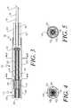
- FIG. 1is a side-elevational view partially in section of an expansile or closure device for obtaining percutaneous access and occlusion of tracts and punctures in the human body incorporating the present invention without the tip guide and having the expansile member in a deployed or expanded position.
- FIG. 2is a side-elevational view partially in section of the device in FIG. 1 with the expansile assembly in a de-deployed or contracted configuration.
- FIG. 3is an exploded side-elevational view in section showing the handle assembly and stop mechanism of the device of FIGS. 1-2.
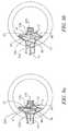
- FIG. 4is a cross-sectional view taken along the line 4 — 4 of FIG. 3 .
- FIG. 5is a cross-sectional view extending distally for several millimeters taken along the line 5 — 5 of FIG. 3 .
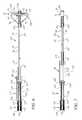
- FIG. 6is a side-elevational view partially in section of another embodiment of the device of the present invention without the tip guide and having the expansile member in the expanded configuration.
- FIG. 7is a side-elevational view partially in section of the device in FIG. 6 with the expansile assembly in a de-deployed or contracted configuration.
- FIGS. 8 a and 8 bare exploded cross-sectional views of the distal extremity of another embodiment of the device of the present invention showing the expansile assembly in the expanded configuration occluding a puncture in a blood vessel.
- FIG. 8 ashows the expansile assembly of the device without proximal tension applied thereto and
- FIG. 8 bshows the expansile assembly of the device with proximal tension applied thereto.
- the device for expansion within an organ having a wall defining a lumen or cavity in the body of the present inventioncomprises an elongated tubular member having proximal and distal extremities and having a longitudinal axis.
- An expansile memberis carried by the distal extremity of the elongated tubular member and is movable between contracted and expanded configurations.
- a deformable membrane at least partially covering the expansile memberis sized so as to be capable of expanding as the expansile member moves from the contracted configuration to the expanded configuration.
- Deployment meansare carried by the proximal extremity of the elongated tubular member and coupled to the expansile member.
- the deployment meansare adapted to be capable of moving the expansile member between the contracted and expanded configurations.
- a handle assemblyis carried by the proximal extremity of the elongated tubular member and coupled to the deployment means.
- the expansile device 21 of the present inventioncomprises a first elongate tubular member 22 , preferably a flexible elongate tubular member 22 , formed of a suitable plastic material, preferably a cast thermoset material such as polyimide.
- a suitable plastic materialpreferably a cast thermoset material such as polyimide.
- the inner and outer surfaces of the polyimide materialmay be coated with a lubricious material such as TeflonTM.
- the thermoset materialmay be a polyimide-TeflonTM composite in order to provide the desired lubricious inner and outer surfaces.
- the first flexible elongate tubular member 22has proximal and distal extremities 23 and 24 with a longitudinal axis extending from the proximal 23 to the distal extremity 24 and is provided with a first lumen 26 circular in cross-section which, as shown, may be centrally disposed extending from the proximal extremity 23 to the distal extremity 24 .
- the flexible elongate tubular member 22is of a suitable size, as for example having an outer diameter ranging from 1-9 French corresponding to an outer diameter ranging from approximately 0.008′′ to 0.050′′, preferably approximately 0.022-0.026, and a suitable length, as for example 10-150 centimeters, preferably 33 centimeters ⁇ 1 centimeter.
- the first lumen 26 in the first flexible elongate tubular member 22may have an inside diameter of approximately 0.003′′ to 0.030′′, preferably 0.012′′-0.014′′.
- Expansile means in the form of an expansile assembly 31is carried by the distal extremity 24 of the flexible elongate tubular member 22 and is movable between contracted and expanded positions.
- a deployment mechanismis carried by the proximal extremity 23 of the flexible elongate tubular member 22 and adapted to be operated by the human hand for movement from a contracted position or configuration to an expanded position or configuration.
- the expansile assembly 31includes an expansile member 32 and a membrane 33 which at least partially covers the expansile member 32 .
- the expansile member 32is in a form having a complex geometrical configuration, preferably a ellipsoidal, helical or bi-conical coil configuration 34 , when in the free, unconstrained state.
- the helical coil 34is formed of a suitable material such as a shape memory or superelastic material which can be elongated, contracted or constrained without permanent deformation but, at body temperature, when freed or unconstrained returns to the memorized helical coil configuration 34 to which it has been annealed.
- a nickel/titanium alloy wireoften called NitinolTM wire.
- the correctly annealed and configured helical coil 34has a plurality of generally circular turns, loops or coils creating, preferably, a proximal coil, loop or turn 66 , a middle coil, turn or loop 67 and a distal coil, turn or loop 68 as shown in FIG. 1 .
- the proximal, middle and distal coils 66 , 67 and 68are generally nonplanar with respect to one another. At least a portion of the proximal coil 66 and a portion of the distal coil 68 each lie in a plane that is generally parallel to one another and generally perpendicular to the longitudinal axis of the flexible elongate tubular member 22 .
- the middle coil 67is non-planar and helical as it connects the proximal and distal coils 66 and 68 so that the unconstrained or free helical coil 34 assumes a substantially ellipsoidal or bi-conical shape.
- the middle coil 67when freed or unconstrained, has a suitable diameter ranging from 3 to 10 millimeters, preferably, greater than or equal to 5.33 millimeters (16 French). As hereinafter discussed, during deployment the middle coil 67 is partially flattened and constrained by the membrane 33 to maintain a diameter of approximately 16 French in order to overlap a puncture site or other opening to assist in occluding the opening.
- the proximal and distal coils 66 and 68are of approximately equal size and diameter ranging from 1 to 5 millimeters, preferably 2 to 3 millimeters.
- the unconstrained helical coil 34 configurationhas a distance from the proximal 66 to the distal 68 coil of approximately 4-8 millimeters.
- the helical coil 34is retracted into the flexible elongate tubular member 22 to obtain the de-deployed configuration wherein the contracted, constrained diameter corresponds to the approximate diameter of the Nitinol wire used to construct the expansile member 32 , ranging from 0.002′′ to 0.010′′, preferably 0.0055′′.
- the expansile member 32is provided with a straight portion 73 of Nitinol wire proximal to the helical coil 34 having a length of approximately 50 millimeters ⁇ 2 millimeters.
- the deployment means or mechanism 80includes a push-pull element or member 81 , preferably in the form of a wire 81 with proximal and distal extremities 82 and 83 , which is slidably disposed in and extends through the first lumen 26 of the flexible elongate tubular member 22 as hereinafter discussed.
- the push-pull member 81is formed of a suitable material such as stainless steel in order optimize torque transmission.
- the push-pull member 81has a suitable diameter ranging from approximately 0.005′′-0.020′′, preferably 0.010′′.
- the distal extremity 83 of the push-pull wire 81provided with a tapered portion 84 .
- the tapered portion 84has a length ranging from approximately 1.0 centimeters to 6.0 centimeters.
- a hypotube connector 101is provided for joining the tapered portion 84 of the push-pull wire 81 to the proximal straight portion 73 of the Nitinol wire 61 .
- the hypotube connector 101has a length ranging from approximately 2.0 centimeters to 4.5 centimeters, an inner diameter ranging from approximately 0.006′′-0.008′′ and an outer diameter ranging from approximately 0.009′′-0.012′′.
- the tapered portion 84 of the push-pull wire 81is inserted into one end of the hypotube connector 101 and the proximal end of the straight portion 73 of the Nitinol wire is inserted into the opposite, distal end of the connector 101 whereupon all are bonded together within the hypotube connector 101 utilizing a suitable adhesive such as LoctiteTM 648.
- a suitable adhesivesuch as LoctiteTM 648.
- the proximal end 23 of the flexible elongate tubular member 22is provided with an expander tube or strain relief member 113 made of a suitable material, such as polycarbonate, having an inner diameter ranging from 0.024′′-0.0281′′, an outer diameter ranging from 0.030′′-0.036′′ and a length of approximately 24-26 millimeters.
- the expander tube 113is disposed over the proximal end 23 of the tubular member 22 so that the proximal end of the expander tube 113 is positioned approximately 0.5-1.0 millimeters distal to the proximal most end 23 of the tubular member 22 and suitably bonded thereto using an appropriate adhesive such as cyanoacrylite:
- a stop mechanism or means 121is provided to control the range of movement or travel of the push-pull wire 81 during deployment and de-deployment of the expansile assembly 31 .
- the stop mechanism 121comprises first and second, or inner and outer, slidably and rotatably nested, or coaxially carried stop members or handles 122 and 123 which are formed of polycarbonate and mounted as hereinafter discussed.
- the inner stop member or handle 122is formed of a polycarbonate extrusion which, initially, has an outer configuration that is square in cross section and has a dimension ranging from approximately 0.015′′-0.050′′, preferably approximately 0.038′′.
- the inner member 122has a length of approximately 60 millimeters ⁇ 5 millimeters and carries a circular in cross section lumen extending therethrough, the lumen having a diameter ranging from approximately 0.010′′-0.016′′.
- the inner stop member 122is twisted or turned in order to form a threaded outer surface or helical groove 125 therein which carries pitches of varying degrees or distances. As shown in FIG. 3, the thread 125 carries, preferably, a greater pitch on the proximal segment of the inner handle 122 and a lesser pitch on the distal segment of the inner handle 122 .
- the distal end of the inner handle 122carries a collar 124 formed of cyanoacrylite and having a length of approximately 3-5 millimeters and an outer diameter ranging from approximately 0.024′′-0.040′′.
- the outer collar 124is coaxially adhesively mounted over the inner handle 122 so that the distal end of the collar 124 is disposed slightly proximal to the distal end of the inner handle tube 122 by several millimeters.
- an inner handle, support hypotube 127is coaxially, adhesively mounted upon the proximal extremity 82 of the push-pull wire 81 using, preferably, cyanoacrylite so that the proximal end thereof is flush with the proximal most tip of the push-pull wire 81 .
- the support hypotube 127has an inner diameter ranging from 0.008′′ to 0.018′′, preferably approximately 0.012′′ and an outer diameter ranging from 0.015′′ to 0.028′′, preferably approximately 0.020′′.
- the inner handle 122is coaxially, adhesively mounted upon the support hypotube 127 , also using an appropriate adhesive such as cyanoacrylite, so that the proximal end 82 of the push-pull wire 81 and the support hypotube 127 carried thereby extend through and proximal of the inner handle 122 as hereinafter discussed.
- the outer handle stop member 123is also constructed of polycarbonate and has a length of approximately 65 millimeters ⁇ 5 millimeters, an inner diameter ranging from approximately 0.020′′-0.060′′, preferably approximately 0.055′′, and an outer diameter ranging from approximately 0.035′′-0.080′′, preferably approximately 0.066′′.
- the proximal end of the outer stop member 123is provided with a slotted stop segment or inner nut or bushing 126 which has an outer diameter equal to the outer diameter of the outer stop member 123 and which is formed so that the slot 126 is square in shape and has a dimension which is, preferably, approximately 0.042′′ or slightly larger than the square, outer dimension of the inner handle 122 . As shown in FIGS.
- the distal end of the outer handle 123is secured to the proximal extremity 23 of the elongate tubular member 22 by being adhesively secured to the proximal end of the expander tube 113 using, preferably, an ultra-violet cured adhesive.
- a freely rotatable handle assembly 131is provided and carried by the segments of the push-pull wire 81 and inner handle support hypotube 127 extending proximal to the inner handle 122 .
- the rotatable handle assembly 131comprises a rotatable hypotube casing 132 , a rotatable collar 133 , a back stop member 134 and a handle grip or sleeve 136 as hereinafter discussed.
- the complete assembly 131is sized so as to be capable of being passed through a conventional introducer sheath as hereinafter described. As such, it has a maximum diameter that is no greater than, and, preferably less than, approximately two to three times the diameter of the elongate tubular member 22 .
- the hypotube casing 132is of appropriate size, having a length of approximately 15 millimeters, an inner diameter of approximately 0.035′′ and an outer diameter of approximately 0.042′′.
- the hypotube casing 132is covered with a handle grip or sleeve 136 made of an approximately 15 millimeters length of RNF heat shrink tubing having a thickness of approximately ⁇ fraction (1/16) ⁇ ′′ and which is applied in a conventional manner.
- the rotatable collar 133is constructed of hypotube having a length of approximately 8 millimeters, an inner diameter of approximately 0.025′′ and an outer diameter of approximately 0.032′′.
- the collar 133is adhesively, coaxially mounted within the casing 132 using an appropriate adhesive, preferably cyanoacrylite, so that the distal end of the collar 133 is flush with the distal end of the casing 132 .
- the rotatable collar 133 carried by the casing 132is coaxially rotatably mounted over the proximal end of the inner handle support hypotube 127 as shown in FIGS. 1-3.
- a back stop member 134constructed of stainless steel hypotube and having a length of approximately 4 millimeters, an inner diameter of approximately 0.025′′ and an outer diameter of approximately 0.032′′ is adhesively, coaxially mounted (also preferably using cyanoacrylite) on the proximal end of the inner handle support tube 127 proximal to the rotatable collar 133 so that the proximal end of the stop member 134 is flush with the tip of the proximal end of the inner handle support tube 127 .
- the push-pull element 81As assembled, the push-pull element 81 , with the threaded inner handle member 122 affixed thereto and the collar 124 carried thereby, is movable longitudinally and rotationally within and in relation to the outer handle member 123 which has its distal extremity secured to the expander hypotube 113 carried by the proximal extremity 23 of the polyimide tubular member 22 as hereinbefore discussed.
- the freely rotatable handle assembly 131it is movable between a forward or distal most position wherein the distal end of the inner handle 122 is engaged with or abutting against the proximal extremity 23 of the polyimide member 22 and the distal end of the rotatable collar 133 abuts against the proximal end of the stop segment 126 of the outer handle member 123 and a rearward or proximal most position wherein the collar 124 is engaged with the stop segment 126 carried by the proximal extremity of the outer member or handle 123 and the proximal end of the rotatable collar 133 abuts against the distal end of the back stop member 134 .
- these positionscorrespond to deployed and de-deployed positions and configurations of the expansile assembly 31 .
- the distal extremity 24 of the flexible elongate tubular member 22is provided with a hypotube tip 105 over which the membrane 33 is disposed and moves as hereinafter discussed.
- the hypotube tip 105is constructed of 304 stainless steel hypotube, or other suitable material, having an outer diameter ranging from approximately 0.028′′-0.040′′ and an inner diameter ranging from 0.024′′-0.030′′ and which is cut to have a length of approximately 3-5 millimeters.
- the hypotube tip 105is coaxially mounted over the distal extremity 24 of the polyimide tubular member 22 using, preferably, Loctite so that the tip of the distal extremity 24 of the tubular member 22 is flush with the distal end of the hypotube tip 105 .
- a tip guide(not shown) is slidably carried by the polyimide tubular member 22 for use as hereinafter discussed.
- the tip guideis constructed of ⁇ fraction (1/16) ⁇ ′′ RNF 100 Shrink tubing.
- the tip guidehas a longitudinal axis and a length of approximately 32 millimeters.
- the distal portion of the tip guideis provided with a larger, non-shrunk end.
- the expansile assembly 31also carries a deformable flexible membrane 33 which is carried by and secured to the distal extremity 24 of the elongate tubular member 22 as shown in FIGS. 1-2.
- the membrane 33is formed of PolyblendTM Extrusion having an internal or inner diameter of 0.020′′, an outer diameter of 0.036′′ and which is cut to have a length of approximately 1 centimeter ⁇ 1.
- the proximal end of the membrane 151is secured to the proximal end of the hypotube tip 105 , using an appropriate material such as Loctite 496 adhesive, so that the distal membrane tip 152 extends distal to the tip of the distal extremity 24 of the flexible elongate tubular member 22 and so that distally extending portion of the membrane tip 152 has a length, measured from the distal end of the hypotube tip 105 to the distal end of the membrane tip 152 , of approximately 1.0-1.5 millimeters.
- the extruded membrane tip 152is subsequently sealed or closed with an extrusion beading 153 as hereinafter discussed.
- the beading 153is made of the same or similar Polyblend material in the form of a solid plug having a diameter of 00.025′′ and a length of 5 millimeters. This segment of extrusion beading 153 is inserted into the distal, open end of the membrane tip 152 approximately 0.5-0.75 millimeters and heat bonded to the membrane tip 152 so that the distal tip of the beading 153 is flush with the distal end of the membrane tip 152 .
- the expansile member 32Prior to deployment, the expansile member 32 is fully or completely retracted within the distal extremity 24 of the flexible elongate tubular member 22 which causes the expansile member 32 to assume a contracted configuration. Insertion of the device 21 in the contracted configuration into a conventional sheath introducer (not shown) is facilitated by using the tip guide 106 carried by the polyimide tubular member 22 as hereinbefore discussed. Prior to inserting the device 21 into the sheath introducer, the operator slides the tip guide 106 distally, from the middle of the polyimide tubular member 22 to the distal extremity 24 thereof.
- the distal end of the tip guide 106When the distal end of the tip guide 106 is disposed slightly distal to the distal extremity 24 of the polyimide tubular member 22 and the membrane 33 carried thereby, the distal end of the tip guide 106 is frictionally fit into the conventional one-way valve carried by the sheath introducer, thus urging the valve into a slightly opened position.
- the distal extremity 24 of the elongate tubular member 22can then be easily and atraumatically introduced through the valve of the introducer and advanced distally therein until the device is aptly disposed through the tract opening or, in the case of a vascular puncture, in the blood vessel as hereinbefore discussed.
- the integrity of the membrane 33 carried therebyis maintained.
- deployment of the device 21is accomplished by using the freely rotatable handle assembly 131 to operate the deployment means 80 to move the push-pull wire 81 distally to urge the expansile member 32 distally out of the lumen 26 of the flexible elongate tubular member 22 , into the membrane 33 .
- the distal part of the expansile member 32clears the lumen 26 , it begins an attempt to expand into its shape memory, predetermined, or free configuration which corresponds to the ellipsoidal, helical coil configuration 34 .
- the expansile member 32is prevented from fully expanding into its free shape configuration as a result of the membrane 33 partially constraining the expansion process.
- the distal coil 71operates to expand the membrane 33 initially to a small degree. This initial process avoids sudden gross distortion of the membrane 33 .
- the non-adherent portion of the membrane 33distal to the portion of membrane 33 fixed to the distal extremity 24 of the elongate tubular member 22 , preferentially begins to move and assume the planar configuration due to the lubricious surface of the hypotube tip 105 and the ease with which the membrane 33 slides thereupon.
- Expansionproceeds with the middle coil 69 causing the membrane 33 to expand to its desired size.
- the proximal coil 68expands last, to centralize and stabilize the configuration so that the push-pull wire 81 is centered with respect to the middle coil 69 and the fully expanded membrane 33 .
- the push-pull member 81is being torqued by the slightly rotating coil 34 in the same direction.
- This torquerequires that the push-pull member 81 be permitted to rotate counter-clockwise in order for the coil 34 to operatively rotate and expand within, and without damaging, the membrane 33 as hereinafter discussed.
- the amount of torque developed by the expanding coil 34varies so that more torque is developed and, therefore, more rotation of the push-pull member 81 is optimal, during deployment of the distal portion of the coil 34 .
- the push-pull member 81rotates approximately 1 to 3, preferably approximately 1.5 to 2, revolutions.
- the variable pitch threaded inner handle 122effects such a counter-clockwise, controlled, torqued deployment.
- the counter-clockwise rotation during deploymentis provided and controlled by rotation means or mechanism which comprises the threaded 125 portion of the inner handle 122 traveling longitudinally and rotationally through the square shaped inner bushing or nut 126 of the outer handle member 123 .
- the lesser or tighter pitch of the thread 125 at the distal segment of the inner handle 122causes greater rotation during deployment of the distal coil 71 .
- the direction of rotation of the expansile memberdepends upon the orientation in which the coil is manufactured. It is, therefore, only important that the rotation means be manufactured to provide controlled rotation in the same direction as that which the coil seeks during expansion according to its manufactured orientation.
- hypotube casing 132 and the rotatable collar 133enable the operator to ergonomically and stably maintain a hand-hold on the handle 131 of the device 21 during operation thereof without having to remove his or her hand in order to accommodate or permit rotation of the inner handle member 122 .
- Thisis effected by the free rotation of the inner handle support tube 127 , the push-pull member 81 and the back stop member 134 within the casing 132 and rotatable collar 133 . That is, the handle assembly 131 accommodates rotation of the deployment means 80 and expansile member 32 without, or independent of, the portions of the handle assembly 131 held by the operator.
- the membrane 33 covering the coil 34simultaneously constrains the coil 34 , thus exerting counteractive or countervailing contractile forces on the expanding coil 34 which is seeking its memorized, ellipsoidal, bi-conical, free or unconstrained configuration.
- the membrane 33does not expand passively. Rather, the expanding coil 34 forcibly expands the membrane 33 to cause the non-planar turns or coils 68 , 69 and 71 of the coil 34 to assume a substantially planar or disk-like configuration with the membrane 33 being taut and disposed on opposite sides of the expansile member 32 to form an expansile assembly 31 which when expanded is generally perpendicular to the longitudinal axis of the first flexible elongate tubular member 22 .
- the expansile member 32when so deployed into this constrained, partially expanded configuration, is sufficiently rigid and robust so as to provide a supporting framework for the membrane 33 to keep it taut and capable of occluding an opening.
- deployment of the expansile assembly 31is effected without obstructing or impinging on walls of the smallest openings in the body due to the uniquely small profile and expansion mechanics of the helical coil 34 during deployment and de-deployment as hereinbefore discussed.
- Device 221is similar to device 21 with the principle difference being in the expanded configuration of device 221 .
- all parts of closure device 221 that are identical to those of device 21carry the same numbers as those of the closure device 21 .
- device 221is provided with means for urging the membrane 33 into a partially convex configuration during movement of expansile member 32 between contracted and expanded configurations to seal a puncture.
- Inner handle 122 of device 221carries a piston 222 which replaces collar 124 in device 21 .
- Piston 222is made of any suitable material, preferably a compressible or deformable silicone O-ring, and is of an appropriate diameter slightly larger than the inner diameter of outer handle 123 .
- Piston or O-ring 222is mounted to inner handle 122 in an appropriate manner similar to that hereinbefore described for collar 124 of device 21 .
- Outer handle 123is provided with a small transverse hole 223 located at a predetermined, appropriate point along the longitudinal axis of outer handle 123 .
- Hole 223has an appropriate diameter ranging from approximately 0.005-0.050 inches, preferably approximately 0.020 inches.
- the primary difference between device 21 and device 221is the configuration that membrane 33 assumes during deployment, when expansile assembly 31 is in the fully expanded configuration, occluding or sealing a vascular puncture.
- piston 222maintains a substantially air-tight seal between inner and outer handles 122 and 123 .
- piston 222is disposed proximal of hole 223 , air naturally contained between inner and outer handles 122 and 123 and within lumen 26 of elongate tubular member 22 is displaced or vented out of outer handle 123 through hole 223 as inner handle 122 moves distally.
- the non-adherent portion of membrane 33distal to the portion of membrane 33 fixed to distal extremity 24 of elongate tubular member 22 , begins to move preferentially.
- the deployment of coil 34 into membrane 33causes the proximal outer surface 224 of membrane 33 to assume a substantially different configuration from the distal outer surface 226 of membrane 33 as seen in FIG. 1 .
- the taper of proximal outer surface 224assumes a substantially convex configuration in the expanded configuration instead of the substantially disk-like configuration of the proximal side of membrane 33 in expanded device 21 .
- distal outer surface 226 of membrane 33 of device 221maintains a disk-like configuration when device 221 is in the fully expanded configuration within the vascular puncture.
- the alteration in taper of proximal outer surface 224 of membrane 33 of device 221occurs at pressures very close to the mean arterial pressure of a human patient.
- the disk-like configured distal outer surface 226 of membrane 33 of expansile assembly 31is naturally urged or forced laterally by arterial blood flow within the vessel, towards the inner wall of the vessel whereby the tapered proximal outer surface 224 is caused to more tightly occlude the puncture in the wall of the vessel without the expansile assembly 31 obstructing ongoing blood flow.
- FIG. 8Another embodiment of the expansile device of the present invention is shown in FIG. 8 .
- Device 231is similar to device 221 with the principle difference being in the expanded configuration of device 231 .
- all parts of closure device 231 that are identical to those of device 221carry the same numbers as those of the closure device 221 .
- device 231is provided with means for urging the proximal outer surface 224 of membrane 33 into a convex configuration during movement of expansile assembly 31 between contracted and expanded configurations that is distinct from the urging means of device 221 .
- Expansile member 32is provided with an additional proximal coil 232 .
- Additional proximal coil 232is of substantially equal size and diameter to proximal coil 66 .
- proximal coils 66 and 232lie immediately adjacent to one another like two-coils of a tightly wound spring.
- the overall unconstrained configuration and size of coil 34is essentially unchanged from that of device 221 .
- second proximal coil 232requires that, in order to be fully deployed, device 231 be provided with a slightly increased stroke length (not shown).
- the proximal outer surface 224 of membrane 33is tented or tapered between the two coils 66 and 232 and assumes a substantially convex configuration as opposed to the substantially disk-like configuration of both sides of membrane 33 assumed by device 21 in the expanded configuration.
- Double coils 66 and 232stretch or unwind less when tension is applied to fully deployed device 231 .
- proximal outer surface 224 of membrane 33is more firmly supported when device 231 is under tension.
- proximal coils 66 and 232they can be made to separate slightly under tension so that during deployment of device 231 , proximal coil 66 remains inside and up against the inner vessel wall of the puncture while proximal coil 232 is made to pull proximally, through the arteriotomy or puncture in the vessel, and come to rest on the outer wall thereof.
- expansile device and methodhave been described principally in use with the human body it should be appreciated that the expansile device and method also can be utilized with animals in a similar manner.
- the expansile devicecan be used within many different natural and iatrogenically created tracts in the body in order to provide for other therapeutic or prophylactic modalities.
Landscapes
- Health & Medical Sciences (AREA)
- Life Sciences & Earth Sciences (AREA)
- Surgery (AREA)
- Molecular Biology (AREA)
- General Health & Medical Sciences (AREA)
- Biomedical Technology (AREA)
- Heart & Thoracic Surgery (AREA)
- Medical Informatics (AREA)
- Nuclear Medicine, Radiotherapy & Molecular Imaging (AREA)
- Animal Behavior & Ethology (AREA)
- Engineering & Computer Science (AREA)
- Public Health (AREA)
- Veterinary Medicine (AREA)
- Reproductive Health (AREA)
- Vascular Medicine (AREA)
- Cardiology (AREA)
- Media Introduction/Drainage Providing Device (AREA)
- Surgical Instruments (AREA)
Abstract
Description
Claims (8)
Priority Applications (3)
| Application Number | Priority Date | Filing Date | Title |
|---|---|---|---|
| US09/528,574US6464712B1 (en) | 1997-02-11 | 2000-03-20 | Expansile device for use in blood vessels and tracts in the body and method |
| US10/272,508US6656207B2 (en) | 1997-02-11 | 2002-10-15 | Expansile device for use in blood vessels and tracts in the body and method |
| US10/718,504US8323305B2 (en) | 1997-02-11 | 2003-11-19 | Expansile device for use in blood vessels and tracts in the body and method |
Applications Claiming Priority (4)
| Application Number | Priority Date | Filing Date | Title |
|---|---|---|---|
| US08/798,870US5782860A (en) | 1997-02-11 | 1997-02-11 | Closure device for percutaneous occlusion of puncture sites and tracts in the human body and method |
| US08/972,383US5922009A (en) | 1997-02-11 | 1997-11-18 | Expansile device for use in blood vessels and tracts in the body and tension application device for use therewith and method |
| US09/241,680US6056770A (en) | 1997-02-11 | 1999-02-01 | Expansile device for use in blood vessels and tracts in the body and method |
| US09/528,574US6464712B1 (en) | 1997-02-11 | 2000-03-20 | Expansile device for use in blood vessels and tracts in the body and method |
Related Parent Applications (1)
| Application Number | Title | Priority Date | Filing Date |
|---|---|---|---|
| US09/241,680Continuation-In-PartUS6056770A (en) | 1997-02-11 | 1999-02-01 | Expansile device for use in blood vessels and tracts in the body and method |
Related Child Applications (1)
| Application Number | Title | Priority Date | Filing Date |
|---|---|---|---|
| US10/272,508ContinuationUS6656207B2 (en) | 1997-02-11 | 2002-10-15 | Expansile device for use in blood vessels and tracts in the body and method |
Publications (1)
| Publication Number | Publication Date |
|---|---|
| US6464712B1true US6464712B1 (en) | 2002-10-15 |
Family
ID=27399501
Family Applications (2)
| Application Number | Title | Priority Date | Filing Date |
|---|---|---|---|
| US09/528,574Expired - LifetimeUS6464712B1 (en) | 1997-02-11 | 2000-03-20 | Expansile device for use in blood vessels and tracts in the body and method |
| US10/272,508Expired - LifetimeUS6656207B2 (en) | 1997-02-11 | 2002-10-15 | Expansile device for use in blood vessels and tracts in the body and method |
Family Applications After (1)
| Application Number | Title | Priority Date | Filing Date |
|---|---|---|---|
| US10/272,508Expired - LifetimeUS6656207B2 (en) | 1997-02-11 | 2002-10-15 | Expansile device for use in blood vessels and tracts in the body and method |
Country Status (1)
| Country | Link |
|---|---|
| US (2) | US6464712B1 (en) |
Cited By (71)
| Publication number | Priority date | Publication date | Assignee | Title |
|---|---|---|---|---|
| US20040176798A1 (en)* | 1997-02-11 | 2004-09-09 | Cardiva Medical, Inc. | Expansile device for use in blood vessels and tracts in the body and method |
| US6814743B2 (en) | 2001-12-26 | 2004-11-09 | Origin Medsystems, Inc. | Temporary seal and method for facilitating anastomosis |
| WO2004069026A3 (en)* | 2003-01-29 | 2005-04-07 | Anulex Technologies Inc | Spinal disc annulus reconstruction method and spinal disc annulus stent |
| US20050228443A1 (en)* | 2004-04-09 | 2005-10-13 | Cardiva Medical, Inc. | Device and method for sealing blood vessels |
| US6966887B1 (en) | 2002-02-27 | 2005-11-22 | Origin Medsystems, Inc. | Temporary arterial shunt and method |
| US20050267522A1 (en)* | 2004-05-27 | 2005-12-01 | Cardiva Medical, Inc. | Self-tensioning vascular occlusion device and method for its use |
| US20050277980A1 (en)* | 2004-05-27 | 2005-12-15 | Cardiva Medical, Inc. | Self-tensioning vascular occlusion device and method for its use |
| US20060064058A1 (en)* | 2004-09-17 | 2006-03-23 | James Coyle | Guiding catheter with embolic protection by proximal occlusion |
| US20060167494A1 (en)* | 2005-01-21 | 2006-07-27 | Loubert Suddaby | Aneurysm repair method and apparatus |
| US7189235B2 (en) | 1999-10-20 | 2007-03-13 | Anulex Technologies, Inc. | Spinal disc annulus reconstruction method and spinal disc annulus stent |
| US20070073333A1 (en)* | 2005-09-26 | 2007-03-29 | Medtronic Vascular, Inc. | Low profile filter assembly for distal embolic protection |
| US20070123817A1 (en)* | 2004-11-05 | 2007-05-31 | Accessclosure, Inc. | Apparatus and Methods for Sealing a Vascular Puncture |
| US20070135837A1 (en)* | 2005-12-13 | 2007-06-14 | Cardiva Medical, Inc. | Drug eluting vascular closure devices and methods |
| US7316704B2 (en) | 2003-06-04 | 2008-01-08 | Accessclosure, Inc. | Occlusion member and tensioner apparatus and methods of their use for sealing a vascular puncture |
| US20080009888A1 (en)* | 2006-07-07 | 2008-01-10 | Usgi Medical, Inc. | Low profile tissue anchors, tissue anchor systems, and methods for their delivery and use |
| US20080135472A1 (en)* | 2004-08-19 | 2008-06-12 | Chaffee Kevin R | Trickling Filter Wastewater Treatment Device |
| US20080154303A1 (en)* | 2006-12-21 | 2008-06-26 | Cardiva Medical, Inc. | Hemostasis-enhancing device and method for its use |
| WO2009006482A1 (en) | 2007-07-02 | 2009-01-08 | Cardiva Medical, Inc. | Vascular closure devices and methods providing hemostatic enhancement |
| US20090254110A1 (en)* | 2008-04-04 | 2009-10-08 | Accessclosure, Inc. | Apparatus and Methods for Sealing a Vascular Puncture |
| US7615076B2 (en) | 1999-10-20 | 2009-11-10 | Anulex Technologies, Inc. | Method and apparatus for the treatment of the intervertebral disc annulus |
| US20100043802A1 (en)* | 2008-08-18 | 2010-02-25 | O'brien John M | Cervical occluder |
| US20100211046A1 (en)* | 2009-02-18 | 2010-08-19 | Aga Medical Corporation | Medical device with stiffener wire for occluding vascular defects |
| US7828850B2 (en) | 1999-10-20 | 2010-11-09 | Anulex Technologies, Inc. | Methods and devices for spinal disc annulus reconstruction and repair |
| US20110046663A1 (en)* | 2009-08-24 | 2011-02-24 | St. Jude Medical Puerto Rico Llc | Polymer membrane locator with built-in stress relief structure |
| US7922768B2 (en) | 1999-10-20 | 2011-04-12 | Anulex Technologies, Inc. | Spinal disc annulus reconstruction method and deformable spinal disc annulus stent |
| US7935147B2 (en) | 1999-10-20 | 2011-05-03 | Anulex Technologies, Inc. | Method and apparatus for enhanced delivery of treatment device to the intervertebral disc annulus |
| US7951201B2 (en) | 1999-10-20 | 2011-05-31 | Anulex Technologies, Inc. | Method and apparatus for the treatment of the intervertebral disc annulus |
| US8052914B2 (en) | 2009-02-20 | 2011-11-08 | Boston Scientific Scimed, Inc. | Modified plug for arteriotomy closure |
| US8128698B2 (en) | 1999-10-20 | 2012-03-06 | Anulex Technologies, Inc. | Method and apparatus for the treatment of the intervertebral disc annulus |
| US8163022B2 (en) | 2008-10-14 | 2012-04-24 | Anulex Technologies, Inc. | Method and apparatus for the treatment of the intervertebral disc annulus |
| US8292918B2 (en) | 2009-02-20 | 2012-10-23 | Boston Scientific Scimed, Inc. | Composite plug for arteriotomy closure and method of use |
| US8317824B2 (en) | 2009-02-20 | 2012-11-27 | Boston Scientific Scimed, Inc. | Tissue puncture closure device |
| US8375553B2 (en) | 2009-02-20 | 2013-02-19 | Boston Scientific Scimed, Inc. | Locking element for vascular closure device |
| US8444673B2 (en) | 2010-02-11 | 2013-05-21 | Boston Scientific Scimed, Inc. | Automatic vascular closure deployment devices and methods |
| US8460319B2 (en) | 2010-01-11 | 2013-06-11 | Anulex Technologies, Inc. | Intervertebral disc annulus repair system and method |
| US8518063B2 (en) | 2001-04-24 | 2013-08-27 | Russell A. Houser | Arteriotomy closure devices and techniques |
| US8529598B2 (en) | 2009-02-20 | 2013-09-10 | Boston Scientific Scimed, Inc. | Tissue puncture closure device |
| US8556977B2 (en) | 1999-10-20 | 2013-10-15 | Anulex Technologies, Inc. | Tissue anchoring system and method |
| US8597340B2 (en) | 2010-09-17 | 2013-12-03 | Boston Scientific Scimed, Inc. | Torque mechanism actuated bioabsorbable vascular closure device |
| US8758402B2 (en) | 2010-12-17 | 2014-06-24 | Boston Scientific Scimed, Inc. | Tissue puncture closure device |
| US20140222059A1 (en)* | 2013-02-05 | 2014-08-07 | Andrew Leopold | Methods and apparatuses for blood vessel occlusion |
| US8911472B2 (en) | 2005-12-13 | 2014-12-16 | Cardiva Medical, Inc. | Apparatus and methods for delivering hemostatic materials for blood vessel closure |
| US8961541B2 (en) | 2007-12-03 | 2015-02-24 | Cardio Vascular Technologies Inc. | Vascular closure devices, systems, and methods of use |
| US8984733B2 (en) | 2013-02-05 | 2015-03-24 | Artventive Medical Group, Inc. | Bodily lumen occlusion |
| US8992567B1 (en) | 2001-04-24 | 2015-03-31 | Cardiovascular Technologies Inc. | Compressible, deformable, or deflectable tissue closure devices and method of manufacture |
| US9017351B2 (en) | 2010-06-29 | 2015-04-28 | Artventive Medical Group, Inc. | Reducing flow through a tubular structure |
| US9149277B2 (en) | 2010-10-18 | 2015-10-06 | Artventive Medical Group, Inc. | Expandable device delivery |
| US9247942B2 (en) | 2010-06-29 | 2016-02-02 | Artventive Medical Group, Inc. | Reversible tubal contraceptive device |
| US9289195B2 (en) | 2003-06-04 | 2016-03-22 | Access Closure, Inc. | Auto-retraction apparatus and methods for sealing a vascular puncture |
| US9345460B2 (en) | 2001-04-24 | 2016-05-24 | Cardiovascular Technologies, Inc. | Tissue closure devices, device and systems for delivery, kits and methods therefor |
| US9364206B2 (en) | 2008-04-04 | 2016-06-14 | Access Closure, Inc. | Apparatus and methods for sealing a vascular puncture |
| US9386968B2 (en) | 2011-05-11 | 2016-07-12 | Access Closure, Inc. | Apparatus and methods for sealing a vascular puncture |
| US9636116B2 (en) | 2013-06-14 | 2017-05-02 | Artventive Medical Group, Inc. | Implantable luminal devices |
| US9730701B2 (en) | 2014-01-16 | 2017-08-15 | Boston Scientific Scimed, Inc. | Retrieval wire centering device |
| US9737306B2 (en) | 2013-06-14 | 2017-08-22 | Artventive Medical Group, Inc. | Implantable luminal devices |
| US9737308B2 (en) | 2013-06-14 | 2017-08-22 | Artventive Medical Group, Inc. | Catheter-assisted tumor treatment |
| US9737294B2 (en) | 2013-01-28 | 2017-08-22 | Cartiva, Inc. | Method and system for orthopedic repair |
| US9795366B2 (en) | 2014-09-18 | 2017-10-24 | Edwards Lifesciences Corporation | Bio-absorbable wound closure device and method |
| US9913634B2 (en) | 2009-02-20 | 2018-03-13 | Boston Scientific Scimed, Inc. | Locking element for vascular closure device |
| US10149968B2 (en) | 2013-06-14 | 2018-12-11 | Artventive Medical Group, Inc. | Catheter-assisted tumor treatment |
| US10179012B2 (en) | 2013-01-28 | 2019-01-15 | Cartiva, Inc. | Systems and methods for orthopedic repair |
| US10363043B2 (en) | 2014-05-01 | 2019-07-30 | Artventive Medical Group, Inc. | Treatment of incompetent vessels |
| US10813644B2 (en) | 2016-04-01 | 2020-10-27 | Artventive Medical Group, Inc. | Occlusive implant and delivery system |
| US11540838B2 (en) | 2019-08-30 | 2023-01-03 | Boston Scientific Scimed, Inc. | Left atrial appendage implant with sealing disk |
| US11903589B2 (en) | 2020-03-24 | 2024-02-20 | Boston Scientific Scimed, Inc. | Medical system for treating a left atrial appendage |
| US11944314B2 (en) | 2019-07-17 | 2024-04-02 | Boston Scientific Scimed, Inc. | Left atrial appendage implant with continuous covering |
| US12318092B2 (en) | 2021-06-22 | 2025-06-03 | Boston Scientific Scimed, Inc. | Left atrial appendage implant |
| US12329500B2 (en) | 2020-11-30 | 2025-06-17 | Boston Scientific Scimed, Inc. | Implantable passive mean pressure sensor |
| US12349918B2 (en) | 2021-09-08 | 2025-07-08 | Boston Scientific Scimed, Inc. | Multi-sharpness split top soft tissue anchors |
| US12383201B2 (en) | 2021-02-03 | 2025-08-12 | Boston Scientific Scimed, Inc. | Medical system for treating a left atrial appendage |
| US12383278B2 (en) | 2021-07-08 | 2025-08-12 | Boston Scientific Scimed, Inc. | Left atrial appendage closure device |
Families Citing this family (20)
| Publication number | Priority date | Publication date | Assignee | Title |
|---|---|---|---|---|
| US8414543B2 (en) | 1999-10-22 | 2013-04-09 | Rex Medical, L.P. | Rotational thrombectomy wire with blocking device |
| US7223266B2 (en) | 2003-02-04 | 2007-05-29 | Cardiodex Ltd. | Methods and apparatus for hemostasis following arterial catheterization |
| US7331976B2 (en) | 2003-04-29 | 2008-02-19 | Rex Medical, L.P. | Distal protection device |
| US7604649B2 (en) | 2003-04-29 | 2009-10-20 | Rex Medical, L.P. | Distal protection device |
| US20060046055A1 (en) | 2004-08-30 | 2006-03-02 | Nan Ya Plastics Corporation | Superfine fiber containing grey dope dyed component and the fabric made of the same |
| EP1814478A4 (en) | 2004-11-22 | 2011-05-18 | Cardiodex Ltd | Techniques for heat-treating varicose veins |
| US7833281B2 (en)* | 2004-12-15 | 2010-11-16 | Lehman Glen A | Method and apparatus for augmentation of a sphincter |
| US7199005B2 (en)* | 2005-08-02 | 2007-04-03 | Micron Technology, Inc. | Methods of forming pluralities of capacitors |
| US20100168767A1 (en)* | 2008-06-30 | 2010-07-01 | Cardiva Medical, Inc. | Apparatus and methods for delivering hemostatic materials for blood vessel closure |
| US20110071455A1 (en)* | 2006-04-06 | 2011-03-24 | Beane Richard M | Method and apparatus for suturelessly connecting a conduit to a hollow organ |
| EP2182875A4 (en) | 2007-08-15 | 2011-08-24 | Cardiodex Ltd | Systems and methods for puncture closure |
| JP5426553B2 (en) | 2007-09-12 | 2014-02-26 | トランスルミナル テクノロジーズ リミテッド ライアビリティー カンパニー | Closure device, placement device, and method of placing a closure device |
| US8876861B2 (en) | 2007-09-12 | 2014-11-04 | Transluminal Technologies, Inc. | Closure device, deployment apparatus, and method of deploying a closure device |
| US9456816B2 (en) | 2007-09-12 | 2016-10-04 | Transluminal Technologies, Llc | Closure device, deployment apparatus, and method of deploying a closure device |
| EP2330981B1 (en) | 2008-08-26 | 2013-11-27 | St. Jude Medical, Inc. | System for sealing percutaneous punctures |
| US8961420B2 (en) | 2010-04-01 | 2015-02-24 | Siemens Medical Solutions Usa, Inc. | System for cardiac condition detection and characterization |
| AU2011326525B2 (en) | 2010-11-09 | 2015-06-18 | Transluminal Technologies, Llc | Specially designed magnesium-aluminum alloys and medical uses thereof in a hemodynamic environment |
| US10342548B2 (en) | 2012-01-13 | 2019-07-09 | W. L. Gore & Associates, Inc. | Occlusion devices and methods of their manufacture and use |
| WO2018200566A1 (en)* | 2017-04-24 | 2018-11-01 | Incuvate, Llc | Systems and methods for embolic protection |
| US11771883B2 (en) | 2021-10-11 | 2023-10-03 | Duke University | Intravascular membrane oxygenator catheter with oscillating hollow fiber membranes |
Citations (7)
| Publication number | Priority date | Publication date | Assignee | Title |
|---|---|---|---|---|
| US5258000A (en) | 1991-11-25 | 1993-11-02 | Cook Incorporated | Tissue aperture repair device |
| US5383896A (en) | 1993-05-25 | 1995-01-24 | Gershony; Gary | Vascular sealing device |
| US5626601A (en) | 1995-10-27 | 1997-05-06 | Gary Gershony | Vascular sealing apparatus and method |
| US5861003A (en) | 1996-10-23 | 1999-01-19 | The Cleveland Clinic Foundation | Apparatus and method for occluding a defect or aperture within body surface |
| US5868778A (en) | 1995-10-27 | 1999-02-09 | Vascular Solutions, Inc. | Vascular sealing apparatus and method |
| US5951583A (en) | 1993-05-25 | 1999-09-14 | Vascular Solutions, Inc. | Thrombin and collagen procoagulant and process for making the same |
| US6017359A (en) | 1993-05-25 | 2000-01-25 | Vascular Solutions, Inc. | Vascular sealing apparatus |
Family Cites Families (9)
| Publication number | Priority date | Publication date | Assignee | Title |
|---|---|---|---|---|
| US4852568A (en) | 1987-02-17 | 1989-08-01 | Kensey Nash Corporation | Method and apparatus for sealing an opening in tissue of a living being |
| US4744364A (en) | 1987-02-17 | 1988-05-17 | Intravascular Surgical Instruments, Inc. | Device for sealing percutaneous puncture in a vessel |
| US4890612A (en) | 1987-02-17 | 1990-01-02 | Kensey Nash Corporation | Device for sealing percutaneous puncture in a vessel |
| ATE107150T1 (en) | 1990-04-02 | 1994-07-15 | Kanji Inoue | DEVICE FOR CLOSING A SHUTTLE OPENING BY A NON-OPERATIONAL METHOD. |
| US5108421A (en) | 1990-10-01 | 1992-04-28 | Quinton Instrument Company | Insertion assembly and method of inserting a vessel plug into the body of a patient |
| US5419765A (en) | 1990-12-27 | 1995-05-30 | Novoste Corporation | Wound treating device and method for treating wounds |
| US5413571A (en)* | 1992-07-16 | 1995-05-09 | Sherwood Medical Company | Device for sealing hemostatic incisions |
| FR2707862B1 (en) | 1993-07-21 | 1995-10-13 | Nycomed Lab Sa | System for temporarily closing an orifice in a perforated organ, such as in particular a vessel. |
| US5634936A (en)* | 1995-02-06 | 1997-06-03 | Scimed Life Systems, Inc. | Device for closing a septal defect |
- 2000
- 2000-03-20USUS09/528,574patent/US6464712B1/ennot_activeExpired - Lifetime
- 2002
- 2002-10-15USUS10/272,508patent/US6656207B2/ennot_activeExpired - Lifetime
Patent Citations (8)
| Publication number | Priority date | Publication date | Assignee | Title |
|---|---|---|---|---|
| US5258000A (en) | 1991-11-25 | 1993-11-02 | Cook Incorporated | Tissue aperture repair device |
| US5383896A (en) | 1993-05-25 | 1995-01-24 | Gershony; Gary | Vascular sealing device |
| US5951583A (en) | 1993-05-25 | 1999-09-14 | Vascular Solutions, Inc. | Thrombin and collagen procoagulant and process for making the same |
| US5957952A (en) | 1993-05-25 | 1999-09-28 | Vascular Solutions, Inc. | Vascular sealing device |
| US6017359A (en) | 1993-05-25 | 2000-01-25 | Vascular Solutions, Inc. | Vascular sealing apparatus |
| US5626601A (en) | 1995-10-27 | 1997-05-06 | Gary Gershony | Vascular sealing apparatus and method |
| US5868778A (en) | 1995-10-27 | 1999-02-09 | Vascular Solutions, Inc. | Vascular sealing apparatus and method |
| US5861003A (en) | 1996-10-23 | 1999-01-19 | The Cleveland Clinic Foundation | Apparatus and method for occluding a defect or aperture within body surface |
Cited By (152)
| Publication number | Priority date | Publication date | Assignee | Title |
|---|---|---|---|---|
| US20040176798A1 (en)* | 1997-02-11 | 2004-09-09 | Cardiva Medical, Inc. | Expansile device for use in blood vessels and tracts in the body and method |
| US8323305B2 (en) | 1997-02-11 | 2012-12-04 | Cardiva Medical, Inc. | Expansile device for use in blood vessels and tracts in the body and method |
| US8034112B2 (en) | 1999-10-20 | 2011-10-11 | Anulex Technologies, Inc. | Spinal disc annulus reconstruction method and spinal disc annulus stent |
| US7951201B2 (en) | 1999-10-20 | 2011-05-31 | Anulex Technologies, Inc. | Method and apparatus for the treatment of the intervertebral disc annulus |
| US7935147B2 (en) | 1999-10-20 | 2011-05-03 | Anulex Technologies, Inc. | Method and apparatus for enhanced delivery of treatment device to the intervertebral disc annulus |
| US7922768B2 (en) | 1999-10-20 | 2011-04-12 | Anulex Technologies, Inc. | Spinal disc annulus reconstruction method and deformable spinal disc annulus stent |
| US7909879B2 (en) | 1999-10-20 | 2011-03-22 | Anulex Technologies, Inc. | Intervertebral disc annulus stent |
| US7963992B2 (en) | 1999-10-20 | 2011-06-21 | Anulex Technologies, Inc. | Method and apparatus for the treatment of the intervertebral disc annulus |
| US7846208B2 (en) | 1999-10-20 | 2010-12-07 | Anulex Technologies, Inc. | Spinal disc annulus reconstruction method and deformable spinal disc annulus stent |
| US20060287731A1 (en)* | 1999-10-20 | 2006-12-21 | Cauthen Joseph C Iii | Spinal disc annulus reconstruction method and deformable spinal disc annulus stent |
| US7189235B2 (en) | 1999-10-20 | 2007-03-13 | Anulex Technologies, Inc. | Spinal disc annulus reconstruction method and spinal disc annulus stent |
| US20070061012A1 (en)* | 1999-10-20 | 2007-03-15 | Cauthen Joseph C Iii | Intervertebral disc annulus stent |
| US7828850B2 (en) | 1999-10-20 | 2010-11-09 | Anulex Technologies, Inc. | Methods and devices for spinal disc annulus reconstruction and repair |
| US9114025B2 (en) | 1999-10-20 | 2015-08-25 | Krt Investors, Inc. | Methods and devices for spinal disc annulus reconstruction and repair |
| US9095442B2 (en) | 1999-10-20 | 2015-08-04 | Krt Investors, Inc. | Method and apparatus for the treatment of the intervertebral disc annulus |
| US7985257B2 (en) | 1999-10-20 | 2011-07-26 | Anulex Technologies, Inc. | Methods and devices for spinal disc annulus reconstruction and repair |
| US7749273B2 (en) | 1999-10-20 | 2010-07-06 | Anulex Technologies, Inc. | Method and apparatus for the treatment of the intervertebral disc annulus |
| US7993405B2 (en) | 1999-10-20 | 2011-08-09 | Anulex Technologies, Inc. | Spinal disc annulus repair system and methods |
| US7670379B2 (en) | 1999-10-20 | 2010-03-02 | Anulex Technologies, Inc. | Spinal disc annulus reconstruction method |
| US7670380B2 (en) | 1999-10-20 | 2010-03-02 | Anulex Technologies, Inc. | Intervertebral disc annulus stent |
| US8632590B2 (en) | 1999-10-20 | 2014-01-21 | Anulex Technologies, Inc. | Apparatus and methods for the treatment of the intervertebral disc |
| US8556977B2 (en) | 1999-10-20 | 2013-10-15 | Anulex Technologies, Inc. | Tissue anchoring system and method |
| US8048160B2 (en) | 1999-10-20 | 2011-11-01 | Anulex Technologies, Inc. | Intervertebral disc annulus stent |
| US8088165B2 (en) | 1999-10-20 | 2012-01-03 | Anulex Technologies, Inc. | Spinal disc annulus reconstruction method and deformable spinal disc annulus stent |
| US7615076B2 (en) | 1999-10-20 | 2009-11-10 | Anulex Technologies, Inc. | Method and apparatus for the treatment of the intervertebral disc annulus |
| US9675347B2 (en) | 1999-10-20 | 2017-06-13 | Krt Investors, Inc. | Apparatus for the treatment of tissue |
| US8128698B2 (en) | 1999-10-20 | 2012-03-06 | Anulex Technologies, Inc. | Method and apparatus for the treatment of the intervertebral disc annulus |
| US8992567B1 (en) | 2001-04-24 | 2015-03-31 | Cardiovascular Technologies Inc. | Compressible, deformable, or deflectable tissue closure devices and method of manufacture |
| US9345460B2 (en) | 2001-04-24 | 2016-05-24 | Cardiovascular Technologies, Inc. | Tissue closure devices, device and systems for delivery, kits and methods therefor |
| US8518063B2 (en) | 2001-04-24 | 2013-08-27 | Russell A. Houser | Arteriotomy closure devices and techniques |
| US9345461B2 (en) | 2001-12-26 | 2016-05-24 | Maquet Cardiovascular Llc | Temporary anastomotic seal and method |
| US11123052B2 (en) | 2001-12-26 | 2021-09-21 | Maquet Cardiovascular Llc | Temporary anastomotic seal and method |
| US7947062B2 (en) | 2001-12-26 | 2011-05-24 | Maquet Cardiovascular Llc | Temporary anastomotic seal and method |
| US7544203B2 (en) | 2001-12-26 | 2009-06-09 | Maquet Cardiovascular Llc | Temporary seal and method for facilitating anastomosis |
| US6814743B2 (en) | 2001-12-26 | 2004-11-09 | Origin Medsystems, Inc. | Temporary seal and method for facilitating anastomosis |
| US6966887B1 (en) | 2002-02-27 | 2005-11-22 | Origin Medsystems, Inc. | Temporary arterial shunt and method |
| WO2004069026A3 (en)* | 2003-01-29 | 2005-04-07 | Anulex Technologies Inc | Spinal disc annulus reconstruction method and spinal disc annulus stent |
| US7316704B2 (en) | 2003-06-04 | 2008-01-08 | Accessclosure, Inc. | Occlusion member and tensioner apparatus and methods of their use for sealing a vascular puncture |
| US7553319B2 (en) | 2003-06-04 | 2009-06-30 | Accessclosure, Inc. | Auto-injector apparatus and methods for sealing a vascular puncture |
| US7985240B2 (en) | 2003-06-04 | 2011-07-26 | Accessclosure, Inc. | Occlusion member and tensioner apparatus and methods of their use for sealing a vascular puncture |
| US9289195B2 (en) | 2003-06-04 | 2016-03-22 | Access Closure, Inc. | Auto-retraction apparatus and methods for sealing a vascular puncture |
| US20080058864A1 (en)* | 2003-06-04 | 2008-03-06 | Accessclosure, Inc. | Occlusion member and tensioner apparatus and methods of their use for sealing a vascular puncture |
| US9017374B2 (en) | 2004-04-09 | 2015-04-28 | Cardiva Medical, Inc. | Device and method for sealing blood vessels |
| US9427221B2 (en) | 2004-04-09 | 2016-08-30 | Cardiva Medical, Inc. | Hemostasis-enhancing device and method for its use |
| US20050228443A1 (en)* | 2004-04-09 | 2005-10-13 | Cardiva Medical, Inc. | Device and method for sealing blood vessels |
| US20090275978A1 (en)* | 2004-05-27 | 2009-11-05 | Cardiva Medical, Inc. | Self-tensioning vascular occlusion device and method for its use |
| US20050277980A1 (en)* | 2004-05-27 | 2005-12-15 | Cardiva Medical, Inc. | Self-tensioning vascular occlusion device and method for its use |
| US7572274B2 (en)* | 2004-05-27 | 2009-08-11 | Cardiva Medical, Inc. | Self-tensioning vascular occlusion device and method for its use |
| US20050267522A1 (en)* | 2004-05-27 | 2005-12-01 | Cardiva Medical, Inc. | Self-tensioning vascular occlusion device and method for its use |
| US7993366B2 (en)* | 2004-05-27 | 2011-08-09 | Cardiva Medical, Inc. | Self-tensioning vascular occlusion device and method for its use |
| US8439944B2 (en) | 2004-05-27 | 2013-05-14 | Cardiva Medical, Inc. | Self-tensioning vascular occlusion device and method for its use |
| US20080135472A1 (en)* | 2004-08-19 | 2008-06-12 | Chaffee Kevin R | Trickling Filter Wastewater Treatment Device |
| US20060064058A1 (en)* | 2004-09-17 | 2006-03-23 | James Coyle | Guiding catheter with embolic protection by proximal occlusion |
| US7344515B2 (en)* | 2004-09-17 | 2008-03-18 | Medtronic Vascular, Inc. | Guiding catheter with embolic protection by proximal occlusion |
| US20070123817A1 (en)* | 2004-11-05 | 2007-05-31 | Accessclosure, Inc. | Apparatus and Methods for Sealing a Vascular Puncture |
| US20080097521A1 (en)* | 2004-11-05 | 2008-04-24 | Accessclosure, Inc. | Apparatus and methods for sealing a vascular puncture |
| US8951283B2 (en) | 2004-11-05 | 2015-02-10 | Access Closure, Inc. | Apparatus and methods for sealing a vascular puncture |
| US10149670B2 (en) | 2004-11-05 | 2018-12-11 | Access Closure, Inc. | Apparatus and methods for sealing a vascular puncture |
| US7803172B2 (en) | 2004-11-05 | 2010-09-28 | Accessclosure, Inc. | Apparatus and methods for sealing a vascular puncture |
| US20060167494A1 (en)* | 2005-01-21 | 2006-07-27 | Loubert Suddaby | Aneurysm repair method and apparatus |
| US20070073333A1 (en)* | 2005-09-26 | 2007-03-29 | Medtronic Vascular, Inc. | Low profile filter assembly for distal embolic protection |
| US10327747B2 (en) | 2005-12-13 | 2019-06-25 | Cardiva Medical, Inc. | Apparatus and methods for delivering hemostatic materials for blood vessel closure |
| US7691127B2 (en) | 2005-12-13 | 2010-04-06 | Cardiva Medical, Inc. | Drug eluting vascular closure devices and methods |
| US9179897B2 (en) | 2005-12-13 | 2015-11-10 | Cardiva Medical, Inc. | Vascular closure devices and methods providing hemostatic enhancement |
| US20070135837A1 (en)* | 2005-12-13 | 2007-06-14 | Cardiva Medical, Inc. | Drug eluting vascular closure devices and methods |
| US8911472B2 (en) | 2005-12-13 | 2014-12-16 | Cardiva Medical, Inc. | Apparatus and methods for delivering hemostatic materials for blood vessel closure |
| US20100145383A1 (en)* | 2005-12-13 | 2010-06-10 | Cardiva Medical, Inc. | Drug eluting vascular closure devices and methods |
| US10363021B2 (en) | 2005-12-13 | 2019-07-30 | Cardiva Medical, Inc. | Vascular closure devices and methods providing hemostatic enhancement |
| US9439637B2 (en) | 2005-12-13 | 2016-09-13 | Cardiva Medical, Inc. | Apparatus and methods for delivering hemostatic materials for blood vessel closure |
| US8747435B2 (en) | 2005-12-13 | 2014-06-10 | Cardiva Medical, Inc. | Drug eluting vascular closure devices and methods |
| US11399815B2 (en) | 2005-12-13 | 2022-08-02 | Cardiva Medical, Inc. | Vascular closure devices and methods providing hemostatic enhancement |
| US20080009888A1 (en)* | 2006-07-07 | 2008-01-10 | Usgi Medical, Inc. | Low profile tissue anchors, tissue anchor systems, and methods for their delivery and use |
| US8870916B2 (en)* | 2006-07-07 | 2014-10-28 | USGI Medical, Inc | Low profile tissue anchors, tissue anchor systems, and methods for their delivery and use |
| US20080154303A1 (en)* | 2006-12-21 | 2008-06-26 | Cardiva Medical, Inc. | Hemostasis-enhancing device and method for its use |
| US10130347B2 (en) | 2006-12-21 | 2018-11-20 | Cardiva Medical, Inc. | Hemostasis-enhancing device and method for its use |
| US8444671B2 (en) | 2006-12-21 | 2013-05-21 | Cardiva Medical, Inc. | Hemostasis-enhancing device and method for its use |
| WO2009006482A1 (en) | 2007-07-02 | 2009-01-08 | Cardiva Medical, Inc. | Vascular closure devices and methods providing hemostatic enhancement |
| US8961541B2 (en) | 2007-12-03 | 2015-02-24 | Cardio Vascular Technologies Inc. | Vascular closure devices, systems, and methods of use |
| US20140180334A1 (en)* | 2008-04-04 | 2014-06-26 | Accessclosure, Inc. | Apparatus and methods for sealing a vascular puncture |
| US11925337B2 (en) | 2008-04-04 | 2024-03-12 | Access Closure, Inc. | Apparatus and methods for sealing a vascular puncture |
| US9364206B2 (en) | 2008-04-04 | 2016-06-14 | Access Closure, Inc. | Apparatus and methods for sealing a vascular puncture |
| US20090254110A1 (en)* | 2008-04-04 | 2009-10-08 | Accessclosure, Inc. | Apparatus and Methods for Sealing a Vascular Puncture |
| US8029533B2 (en)* | 2008-04-04 | 2011-10-04 | Accessclosure, Inc. | Apparatus and methods for sealing a vascular puncture |
| US11707265B2 (en) | 2008-04-04 | 2023-07-25 | Access Closure, Inc. | Apparatus and methods for sealing a vascular puncture |
| US10512455B2 (en) | 2008-04-04 | 2019-12-24 | Access Closure, Inc. | Apparatus and methods for sealing a vascular puncture |
| US10595838B2 (en)* | 2008-04-04 | 2020-03-24 | Accessclosure, Inc. | Apparatus and methods for sealing a vascular puncture |
| US11717278B2 (en) | 2008-06-30 | 2023-08-08 | Cardiva Medical, Inc. | Apparatus and methods for delivering hemostatic materials for blood vessel closure |
| WO2010021695A1 (en)* | 2008-08-18 | 2010-02-25 | O'brien John M | Cervical occluder |
| US8408212B2 (en) | 2008-08-18 | 2013-04-02 | Glenveigh Medical, Llc | Cervical occluder |
| CN102368966B (en)* | 2008-08-18 | 2014-12-03 | 约翰·M·奥布莱恩 | Cervical occlusion body |
| US20100043802A1 (en)* | 2008-08-18 | 2010-02-25 | O'brien John M | Cervical occluder |
| US8454697B2 (en) | 2008-10-14 | 2013-06-04 | Anulex Technologies, Inc. | Method and apparatus for the treatment of tissue |
| US9192372B2 (en) | 2008-10-14 | 2015-11-24 | Krt Investors, Inc. | Method for the treatment of tissue |
| US8163022B2 (en) | 2008-10-14 | 2012-04-24 | Anulex Technologies, Inc. | Method and apparatus for the treatment of the intervertebral disc annulus |
| US20100211046A1 (en)* | 2009-02-18 | 2010-08-19 | Aga Medical Corporation | Medical device with stiffener wire for occluding vascular defects |
| US10702275B2 (en)* | 2009-02-18 | 2020-07-07 | St. Jude Medical Cardiology Division, Inc. | Medical device with stiffener wire for occluding vascular defects |
| US8529598B2 (en) | 2009-02-20 | 2013-09-10 | Boston Scientific Scimed, Inc. | Tissue puncture closure device |
| US9282955B2 (en) | 2009-02-20 | 2016-03-15 | Boston Scientific Scimed, Inc. | Tissue puncture closure device |
| US9913634B2 (en) | 2009-02-20 | 2018-03-13 | Boston Scientific Scimed, Inc. | Locking element for vascular closure device |
| US8292918B2 (en) | 2009-02-20 | 2012-10-23 | Boston Scientific Scimed, Inc. | Composite plug for arteriotomy closure and method of use |
| US8052914B2 (en) | 2009-02-20 | 2011-11-08 | Boston Scientific Scimed, Inc. | Modified plug for arteriotomy closure |
| US8317824B2 (en) | 2009-02-20 | 2012-11-27 | Boston Scientific Scimed, Inc. | Tissue puncture closure device |
| US8375553B2 (en) | 2009-02-20 | 2013-02-19 | Boston Scientific Scimed, Inc. | Locking element for vascular closure device |
| US10363020B2 (en) | 2009-02-20 | 2019-07-30 | Boston Scientific Scimed Inc. | Composite plug for arteriotomy closure and method of use |
| US9820726B2 (en)* | 2009-08-24 | 2017-11-21 | St. Jude Medical Puerto Rico Llc | Polymer membrane locator with built-in stress relief structure |
| US20110046663A1 (en)* | 2009-08-24 | 2011-02-24 | St. Jude Medical Puerto Rico Llc | Polymer membrane locator with built-in stress relief structure |
| US9795372B2 (en) | 2010-01-11 | 2017-10-24 | Krt Investors, Inc. | Intervertebral disc annulus repair system and bone anchor delivery tool |
| US8460319B2 (en) | 2010-01-11 | 2013-06-11 | Anulex Technologies, Inc. | Intervertebral disc annulus repair system and method |
| US8652153B2 (en) | 2010-01-11 | 2014-02-18 | Anulex Technologies, Inc. | Intervertebral disc annulus repair system and bone anchor delivery tool |
| US9301740B2 (en) | 2010-02-11 | 2016-04-05 | Boston Scientific Scimed, Inc. | Automatic vascular closure deployment devices and methods |
| US8444673B2 (en) | 2010-02-11 | 2013-05-21 | Boston Scientific Scimed, Inc. | Automatic vascular closure deployment devices and methods |
| US9017351B2 (en) | 2010-06-29 | 2015-04-28 | Artventive Medical Group, Inc. | Reducing flow through a tubular structure |
| US9247942B2 (en) | 2010-06-29 | 2016-02-02 | Artventive Medical Group, Inc. | Reversible tubal contraceptive device |
| US9451965B2 (en) | 2010-06-29 | 2016-09-27 | Artventive Medical Group, Inc. | Reducing flow through a tubular structure |
| US8597340B2 (en) | 2010-09-17 | 2013-12-03 | Boston Scientific Scimed, Inc. | Torque mechanism actuated bioabsorbable vascular closure device |
| US9149277B2 (en) | 2010-10-18 | 2015-10-06 | Artventive Medical Group, Inc. | Expandable device delivery |
| US8758402B2 (en) | 2010-12-17 | 2014-06-24 | Boston Scientific Scimed, Inc. | Tissue puncture closure device |
| US9386968B2 (en) | 2011-05-11 | 2016-07-12 | Access Closure, Inc. | Apparatus and methods for sealing a vascular puncture |
| US11534150B2 (en) | 2011-05-11 | 2022-12-27 | Access Closure, Inc. | Apparatus and methods for sealing a vascular puncture |
| US10314567B2 (en) | 2011-05-11 | 2019-06-11 | Access Closure | Apparatus and methods for sealing a vascular puncture |
| US11471199B2 (en) | 2013-01-28 | 2022-10-18 | Cartiva, Inc. | Systems and methods for orthopedic repair |
| US9737294B2 (en) | 2013-01-28 | 2017-08-22 | Cartiva, Inc. | Method and system for orthopedic repair |
| US10179012B2 (en) | 2013-01-28 | 2019-01-15 | Cartiva, Inc. | Systems and methods for orthopedic repair |
| US9095344B2 (en)* | 2013-02-05 | 2015-08-04 | Artventive Medical Group, Inc. | Methods and apparatuses for blood vessel occlusion |
| US9737307B2 (en)* | 2013-02-05 | 2017-08-22 | Artventive Medical Group, Inc. | Blood vessel occlusion |
| US9107669B2 (en)* | 2013-02-05 | 2015-08-18 | Artventive Medical Group, Inc. | Blood vessel occlusion |
| US8984733B2 (en) | 2013-02-05 | 2015-03-24 | Artventive Medical Group, Inc. | Bodily lumen occlusion |
| US20140257369A1 (en)* | 2013-02-05 | 2014-09-11 | Artventive Medical Group, Inc. | Blood vessel occlusion |
| US20140222059A1 (en)* | 2013-02-05 | 2014-08-07 | Andrew Leopold | Methods and apparatuses for blood vessel occlusion |
| US10004513B2 (en) | 2013-02-05 | 2018-06-26 | Artventive Medical Group, Inc. | Bodily lumen occlusion |
| US9737308B2 (en) | 2013-06-14 | 2017-08-22 | Artventive Medical Group, Inc. | Catheter-assisted tumor treatment |
| US10441290B2 (en) | 2013-06-14 | 2019-10-15 | Artventive Medical Group, Inc. | Implantable luminal devices |
| US9737306B2 (en) | 2013-06-14 | 2017-08-22 | Artventive Medical Group, Inc. | Implantable luminal devices |
| US9636116B2 (en) | 2013-06-14 | 2017-05-02 | Artventive Medical Group, Inc. | Implantable luminal devices |
| US10149968B2 (en) | 2013-06-14 | 2018-12-11 | Artventive Medical Group, Inc. | Catheter-assisted tumor treatment |
| US12193678B2 (en) | 2014-01-16 | 2025-01-14 | Boston Scientific Scimed, Inc. | Retrieval wire centering device |
| US9730701B2 (en) | 2014-01-16 | 2017-08-15 | Boston Scientific Scimed, Inc. | Retrieval wire centering device |
| US10463377B2 (en) | 2014-01-16 | 2019-11-05 | Boston Scientific Scimed, Inc. | Retrieval wire centering device |
| US11413047B2 (en) | 2014-01-16 | 2022-08-16 | Cardiac Pacemakers, Inc. | Occlusive medical implant |
| US11224438B2 (en) | 2014-05-01 | 2022-01-18 | Artventive Medical Group, Inc. | Treatment of incompetent vessels |
| US10363043B2 (en) | 2014-05-01 | 2019-07-30 | Artventive Medical Group, Inc. | Treatment of incompetent vessels |
| US9795366B2 (en) | 2014-09-18 | 2017-10-24 | Edwards Lifesciences Corporation | Bio-absorbable wound closure device and method |
| US10813644B2 (en) | 2016-04-01 | 2020-10-27 | Artventive Medical Group, Inc. | Occlusive implant and delivery system |
| US11944314B2 (en) | 2019-07-17 | 2024-04-02 | Boston Scientific Scimed, Inc. | Left atrial appendage implant with continuous covering |
| US11540838B2 (en) | 2019-08-30 | 2023-01-03 | Boston Scientific Scimed, Inc. | Left atrial appendage implant with sealing disk |
| US11903589B2 (en) | 2020-03-24 | 2024-02-20 | Boston Scientific Scimed, Inc. | Medical system for treating a left atrial appendage |
| US12329500B2 (en) | 2020-11-30 | 2025-06-17 | Boston Scientific Scimed, Inc. | Implantable passive mean pressure sensor |
| US12383201B2 (en) | 2021-02-03 | 2025-08-12 | Boston Scientific Scimed, Inc. | Medical system for treating a left atrial appendage |
| US12318092B2 (en) | 2021-06-22 | 2025-06-03 | Boston Scientific Scimed, Inc. | Left atrial appendage implant |
| US12336715B2 (en) | 2021-06-22 | 2025-06-24 | Boston Scientific Scimed, Inc. | Left atrial appendage implant |
| US12383278B2 (en) | 2021-07-08 | 2025-08-12 | Boston Scientific Scimed, Inc. | Left atrial appendage closure device |
| US12349918B2 (en) | 2021-09-08 | 2025-07-08 | Boston Scientific Scimed, Inc. | Multi-sharpness split top soft tissue anchors |
Also Published As
| Publication number | Publication date |
|---|---|
| US20030163146A1 (en) | 2003-08-28 |
| US6656207B2 (en) | 2003-12-02 |
Similar Documents
| Publication | Publication Date | Title |
|---|---|---|
| US6464712B1 (en) | Expansile device for use in blood vessels and tracts in the body and method | |
| US6056770A (en) | Expansile device for use in blood vessels and tracts in the body and method | |
| US8323305B2 (en) | Expansile device for use in blood vessels and tracts in the body and method | |
| US9913635B2 (en) | Vascular closure device having a flowable sealing material | |
| AU2017322329B2 (en) | System for suture trimming | |
| US5922009A (en) | Expansile device for use in blood vessels and tracts in the body and tension application device for use therewith and method | |
| US6056769A (en) | Expansile device for use in blood vessels and tracts in the body and tension application device for use therewith and method | |
| US5292332A (en) | Methods and device for percutanceous sealing of arterial puncture sites | |
| JP5341816B2 (en) | Access and occlusion devices and methods | |
| US5951589A (en) | Expansile device for use in blood vessels and tracts in the body and tension application device for use therewith and method | |
| JP4954063B2 (en) | Hemostatic device | |
| JP2003024335A (en) | Tamping mechanism for sealing method | |
| AU2018334225B2 (en) | Arteriotomy positioning device and method of use therefor | |
| CN112107342B (en) | Blood flow control devices | |
| JP7423191B2 (en) | Spiral balloon auxiliary device and its usage |
Legal Events
| Date | Code | Title | Description |
|---|---|---|---|
| AS | Assignment | Owner name:BIOINTERVENTIONAL CORPORATION, CALIFORNIA Free format text:ASSIGNMENT OF ASSIGNORS INTEREST;ASSIGNORS:EPSTEIN, GORDON H.;LEMPERT, TODD E.;MARTIN, BRIAN B.;AND OTHERS;REEL/FRAME:010966/0880;SIGNING DATES FROM 20000419 TO 20000724 | |
| STCF | Information on status: patent grant | Free format text:PATENTED CASE | |
| AS | Assignment | Owner name:CARDIVA MEDICAL INC., CALIFORNIA Free format text:ASSIGNMENT OF ASSIGNORS INTEREST;ASSIGNOR:CARDIVA MEDICAL, INC.;REEL/FRAME:013645/0447 Effective date:20021210 | |
| AS | Assignment | Owner name:CARDIVA MEDICAL, INC., CALIFORNIA Free format text:ASSIGNMENT OF ASSIGNORS INTEREST;ASSIGNOR:BIOINTERVENTIONAL CORPORATION;REEL/FRAME:013684/0116 Effective date:20030527 | |
| FPAY | Fee payment | Year of fee payment:4 | |
| FPAY | Fee payment | Year of fee payment:8 | |
| AS | Assignment | Owner name:COMERICA BANK, A TEXAS BANKING ASSOCIATION,MICHIGA Free format text:SECURITY AGREEMENT;ASSIGNOR:CARDIVA MEDICAL, INC.;REEL/FRAME:024329/0775 Effective date:20100405 Owner name:COMERICA BANK, A TEXAS BANKING ASSOCIATION, MICHIG Free format text:SECURITY AGREEMENT;ASSIGNOR:CARDIVA MEDICAL, INC.;REEL/FRAME:024329/0775 Effective date:20100405 | |
| FPAY | Fee payment | Year of fee payment:12 | |
| SULP | Surcharge for late payment | Year of fee payment:11 | |
| AS | Assignment | Owner name:GENERAL ELECTRIC CAPITAL CORPORATION, AS AGENT, MA Free format text:SECURITY INTEREST;ASSIGNOR:CARDIVA MEDICAL, INC.;REEL/FRAME:033449/0021 Effective date:20140724 | |
| AS | Assignment | Owner name:CARDIVA MEDICAL, INC., CALIFORNIA Free format text:RELEASE OF SECURITY INTEREST;ASSIGNOR:COMERICA BANK;REEL/FRAME:033531/0892 Effective date:20140805 | |
| AS | Assignment | Owner name:CARDIVA MEDICAL, INC., CALIFORNIA Free format text:RELEASE BY SECURED PARTY;ASSIGNOR:GENERAL ELECTRIC CAPITAL CORPORATION;REEL/FRAME:041388/0523 Effective date:20150819 |