US6463938B2 - Wafer cleaning method - Google Patents
Wafer cleaning methodDownload PDFInfo
- Publication number
- US6463938B2 US6463938B2US09/953,504US95350401AUS6463938B2US 6463938 B2US6463938 B2US 6463938B2US 95350401 AUS95350401 AUS 95350401AUS 6463938 B2US6463938 B2US 6463938B2
- Authority
- US
- United States
- Prior art keywords
- wafer
- probe
- article
- transmitter
- transducer
- Prior art date
- Legal status (The legal status is an assumption and is not a legal conclusion. Google has not performed a legal analysis and makes no representation as to the accuracy of the status listed.)
- Expired - Lifetime
Links
Images


Classifications
- H—ELECTRICITY
- H01—ELECTRIC ELEMENTS
- H01L—SEMICONDUCTOR DEVICES NOT COVERED BY CLASS H10
- H01L21/00—Processes or apparatus adapted for the manufacture or treatment of semiconductor or solid state devices or of parts thereof
- H01L21/02—Manufacture or treatment of semiconductor devices or of parts thereof
- H01L21/02041—Cleaning
- B—PERFORMING OPERATIONS; TRANSPORTING
- B08—CLEANING
- B08B—CLEANING IN GENERAL; PREVENTION OF FOULING IN GENERAL
- B08B17/00—Methods preventing fouling
- B08B17/02—Preventing deposition of fouling or of dust
- H—ELECTRICITY
- H01—ELECTRIC ELEMENTS
- H01L—SEMICONDUCTOR DEVICES NOT COVERED BY CLASS H10
- H01L21/00—Processes or apparatus adapted for the manufacture or treatment of semiconductor or solid state devices or of parts thereof
- H01L21/02—Manufacture or treatment of semiconductor devices or of parts thereof
- H01L21/04—Manufacture or treatment of semiconductor devices or of parts thereof the devices having potential barriers, e.g. a PN junction, depletion layer or carrier concentration layer
- H01L21/18—Manufacture or treatment of semiconductor devices or of parts thereof the devices having potential barriers, e.g. a PN junction, depletion layer or carrier concentration layer the devices having semiconductor bodies comprising elements of Group IV of the Periodic Table or AIIIBV compounds with or without impurities, e.g. doping materials
- H01L21/30—Treatment of semiconductor bodies using processes or apparatus not provided for in groups H01L21/20 - H01L21/26
- H01L21/302—Treatment of semiconductor bodies using processes or apparatus not provided for in groups H01L21/20 - H01L21/26 to change their surface-physical characteristics or shape, e.g. etching, polishing, cutting
- H01L21/304—Mechanical treatment, e.g. grinding, polishing, cutting
- B—PERFORMING OPERATIONS; TRANSPORTING
- B06—GENERATING OR TRANSMITTING MECHANICAL VIBRATIONS IN GENERAL
- B06B—METHODS OR APPARATUS FOR GENERATING OR TRANSMITTING MECHANICAL VIBRATIONS OF INFRASONIC, SONIC, OR ULTRASONIC FREQUENCY, e.g. FOR PERFORMING MECHANICAL WORK IN GENERAL
- B06B3/00—Methods or apparatus specially adapted for transmitting mechanical vibrations of infrasonic, sonic, or ultrasonic frequency
- B—PERFORMING OPERATIONS; TRANSPORTING
- B08—CLEANING
- B08B—CLEANING IN GENERAL; PREVENTION OF FOULING IN GENERAL
- B08B3/00—Cleaning by methods involving the use or presence of liquid or steam
- B08B3/04—Cleaning involving contact with liquid
- B08B3/10—Cleaning involving contact with liquid with additional treatment of the liquid or of the object being cleaned, e.g. by heat, by electricity or by vibration
- B08B3/12—Cleaning involving contact with liquid with additional treatment of the liquid or of the object being cleaned, e.g. by heat, by electricity or by vibration by sonic or ultrasonic vibrations
- H—ELECTRICITY
- H01—ELECTRIC ELEMENTS
- H01L—SEMICONDUCTOR DEVICES NOT COVERED BY CLASS H10
- H01L21/00—Processes or apparatus adapted for the manufacture or treatment of semiconductor or solid state devices or of parts thereof
- H01L21/67—Apparatus specially adapted for handling semiconductor or electric solid state devices during manufacture or treatment thereof; Apparatus specially adapted for handling wafers during manufacture or treatment of semiconductor or electric solid state devices or components ; Apparatus not specifically provided for elsewhere
- H01L21/67005—Apparatus not specifically provided for elsewhere
- H01L21/67011—Apparatus for manufacture or treatment
- H01L21/67017—Apparatus for fluid treatment
- H01L21/67028—Apparatus for fluid treatment for cleaning followed by drying, rinsing, stripping, blasting or the like
- H01L21/6704—Apparatus for fluid treatment for cleaning followed by drying, rinsing, stripping, blasting or the like for wet cleaning or washing
- H01L21/67051—Apparatus for fluid treatment for cleaning followed by drying, rinsing, stripping, blasting or the like for wet cleaning or washing using mainly spraying means, e.g. nozzles
- H—ELECTRICITY
- H01—ELECTRIC ELEMENTS
- H01L—SEMICONDUCTOR DEVICES NOT COVERED BY CLASS H10
- H01L21/00—Processes or apparatus adapted for the manufacture or treatment of semiconductor or solid state devices or of parts thereof
- H01L21/67—Apparatus specially adapted for handling semiconductor or electric solid state devices during manufacture or treatment thereof; Apparatus specially adapted for handling wafers during manufacture or treatment of semiconductor or electric solid state devices or components ; Apparatus not specifically provided for elsewhere
- H01L21/67005—Apparatus not specifically provided for elsewhere
- H01L21/67011—Apparatus for manufacture or treatment
- H01L21/67017—Apparatus for fluid treatment
- H01L21/67028—Apparatus for fluid treatment for cleaning followed by drying, rinsing, stripping, blasting or the like
- H01L21/6704—Apparatus for fluid treatment for cleaning followed by drying, rinsing, stripping, blasting or the like for wet cleaning or washing
- H01L21/67057—Apparatus for fluid treatment for cleaning followed by drying, rinsing, stripping, blasting or the like for wet cleaning or washing with the semiconductor substrates being dipped in baths or vessels
- Y—GENERAL TAGGING OF NEW TECHNOLOGICAL DEVELOPMENTS; GENERAL TAGGING OF CROSS-SECTIONAL TECHNOLOGIES SPANNING OVER SEVERAL SECTIONS OF THE IPC; TECHNICAL SUBJECTS COVERED BY FORMER USPC CROSS-REFERENCE ART COLLECTIONS [XRACs] AND DIGESTS
- Y10—TECHNICAL SUBJECTS COVERED BY FORMER USPC
- Y10S—TECHNICAL SUBJECTS COVERED BY FORMER USPC CROSS-REFERENCE ART COLLECTIONS [XRACs] AND DIGESTS
- Y10S134/00—Cleaning and liquid contact with solids
- Y10S134/902—Semiconductor wafer
Definitions
- This inventionrelates to an apparatus and method for cleaning semiconductor wafers or other such items requiring extremely high levels of cleanliness.
- Megasonic energy cleaning apparatusestypically comprise a piezoelectric transducer coupled to a transmitter.
- the transduceris electrically excited such that it vibrates, and the transmitter transmits high frequency energy into liquid in a processing tank.
- the agitation of the cleaning fluid produced by the megasonic energyloosens particles on the semiconductor wafers. Contaminants are thus vibrated away from the surfaces of the wafer.
- fluidenters the wet processing container from the bottom of the tank and overflows the container at the top. Contaminants may thus be removed from the tank through the overflow of the fluid and by quickly dumping the fluid.
- a process for cleaning by cavitation in liquefied gasis disclosed in U.S. Pat. No. 5,316,591, issued to Chao et al. Undesired material is removed from a substrate by introducing a liquefied gas into a cleaning chamber and exposing the liquefied gas to cavitation-producing means.
- the shape of the horn to provide the cavitationis not disclosed in detail and does not concentrate the sonic agitation to a particular location within the cleaning vessel.
- the above-referenced parent patent applicationclaims various forms of the invention.
- Thisincludes a housing having an end wall with a vibrator or transducer, such as a piezoelectric transducer coupled to an interior surface of the end wall, while an elongated probe has an end coupled to an exterior surface of the housing end wall.
- the transducerwhen energized propagates megasonic energy through the housing end wall and into the probe.
- the housingis preferably made of aluminum of other material having good thermal conductivity so that heat generated by the transducer is dissipated through the housing.
- a liquid coolant passageis formed in heat transfer relation with the housing. Preferably, this is accomplished by positioning a heat transfer member in the housing in a manner to form the passage in combination with an interior wall of the housing. Coolant is then conducted through this passage to provide the desired cooling effect.
- the transduceris sealed from the liquid coolant, but nitrogen or other gas may be conducted into the housing, preferably through the heat transfer member, to provide gaseous cooling for the transducer.
- the probeis coupled to the housing by positioning a layer of viscous material between the housing end wall and the probe and pressing the probe against the housing end wall.
- the pressing forceis provided by compressing a spring against the probe with a spring retainer plate which is clamped to the housing.
- an O-ringsurrounds the interface between the probe and the housing end wall to confine the viscous material and to center the probe, and is clamped in position by a retaining ring mounted to the housing end wall.
- a significant advantage of this embodimentis that the housing end wall through which the vibrational energy is transmitted is much thinner than the heat transfer member which is positioned between the probe and the transducer in the other embodiments. This reduced mass allows increased energy to be transmitted to the probe with the same electrical input.
- the thin wallhas fewer internal reflections of energy and makes tuning the transducer easier. Nevertheless, approximately the same cooling capacity is provided with a housing and a heat transfer member having a size comparable to that of the other embodiments.
- a thin wall of a heat transfer memberis sandwiched between the transducer and the probe.
- Surrounding the thin wallis an elongated annular wall of the heat transfer member, which in turn fits snugly within a surrounding cylindrical housing.
- a channel formed in the exterior surface of the annular wall of the heat transfer memberforms a coolant passage in combination with the housing.
- An O-ring surrounding the base of the probeis held in position by a retaining ring fastened to the end of the housing. Since the base or rear of the probe extends into the housing, the retainer ring includes a cylindrical portion that extends into the housing to engage the O-ring.
- An advantage of this embodiment of the inventionis that the megasonic energy can be efficiently transmitted by the transducer through the thin wall of the heat transfer member into the probe, while at the same time providing excellent cooling characteristics because of a direct path from the transducer through the heat transfer member to the cooling fluid passage.
- a probemade of a base having a socket formed therein for receiving an elongated rod portion preferably having a constant cross-section.
- the base and rodare coupled in a manner to efficiently transmit the megasonic energy from the base to the rod.
- An advantage of this arrangementis that a single base can be used for rods of different materials and lengths which are to be contacted by a cleaning fluid.
- a quartz basemay be used for many applications, while a rod of different material may be used with a solution containing hydrofluoric acid, which is not compatible with quartz.
- some materialssuch as vitreous carbon can withstand most cleaning solutions but the material is presently only readily available in constant diameter rod form.
- FIG. 1is a side elevational view of one embodiment of the megasonic energy cleaning system of the present invention.
- FIG. 2is a side cross-sectional view of the system shown in FIG. 1 .
- FIG. 3is an exploded perspective view of the probe assembly shown in FIG. 1 .
- FIG. 4is a side view of an alternative probe in accordance with the present invention.
- FIGS. 5 a- 5 care alternative probe tips which may be used in connection with the present invention.
- FIG. 6is a schematic view of the probe of the present invention used with cleaning fluid being sprayed onto the upper surface of a wafer.
- FIG. 7is a cross-sectional view on line 7 — 7 of FIG. 6 .
- FIG. 8is a schematic view of the probe cleaning both surfaces of a wafer.
- FIG. 9is a schematic view of the probe of FIG. 1 extending through discs to be cleaned.
- FIG. 9 ais a fragmentary, cross sectional view of a cap for a probe tip.
- FIG. 9 bis a fragmentary, cross sectional view of another probe tip cap.
- FIG. 10is a schematic view of a probe vertically oriented with respect to a wafer.
- FIG. 11a side elevational, partially sectionalized view of another embodiment of the invention having an alternate means of coupling the probe to a support.
- FIG. 12is a side elevational, partially sectionalized view of another embodiment of the invention having an alternate means of mounting the probe to the housing.
- FIG. 13is a side elevational, partially sectionalized view of another embodiment of the invention having an alternate arrangement for mounting the probe and an alternate probe construction.
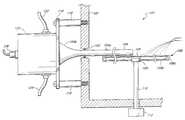
- FIGS. 1-3illustrate a megasonic energy cleaning apparatus made in accordance with the present invention with an elongated probe 104 inserted through the wall 100 of a processing tank 101 .
- the probeis supported in cantilever fashion on one end exterior of the container.
- a suitable O-ring 102sandwiched between the probe 104 and the tank wall, provides a proper seal for the processing tank 101 .
- a heat transfer member 134contained within a housing 120 , is acoustically and mechanically coupled to the probe 104 .
- a piezoelectric transducer 140acoustically coupled to the heat transfer member 134 .
- Electrical connectors 142 , 154 , and 126are connected between the transducer 140 and a source of acoustic energy (not shown).
- the housingsupports an inlet conduit 124 and an outlet conduit 122 for coolant and has an opening 152 for electrical connectors.
- the housingis closed by an annular plate 118 with an opening 132 for the probe. The plate in turn is attached to the tank.
- a support or susceptor 108is positioned parallel to and in close proximity to the probe 104 .
- the susceptor 108may take various forms, the arrangement illustrated including an outer rim 108 a supported by a plurality of spokes 108 b connected to a hub 108 c supported on a shaft 110 , which extends through a bottom wall of the processing tank 101 .
- the shaft 110is connected to a motor 112 .
- the elongated probe 104is preferably made of a relatively inert, non-contaminating material, such as quartz, which efficiently transmits acoustic energy. While utilizing a quartz probe is satisfactory for most cleaning solutions, solutions containing hydrofluoric acid can etch quartz. Thus, a probe made of sapphire silicon carbide, boron nitride, vitreous carbon, glassy carbon coated graphite, or other suitable materials may be employed instead of quartz. Also, quartz may be coated by a material that can withstand HF such as silicon carbide or vitreous carbon.
- the probe 104comprises a solid, elongated, constant cross-section spindle-like or rod-like cleaning portion 104 a, and a base or rear portion 104 b.
- the cross-section of the probeis preferably round and advantageously, the diameter of the cleaning portion of the probe is smaller in diameter than the rear portion of the probe.
- the area of the rear face of the rear portion 104 bis 25 times that of the tip face of portion 104 a.
- cross-sectional shapes other than circularmay be employed.
- a cylindrically-shaped rod portion 104 a having a small diameteris desirable to concentrate the megasonic energy along the length of the rod 104 a.
- the diameter of the probeshould be sufficient to withstand mechanical vibration produced by the megasonic energy transmitted by the probe.
- the radius of the rod portion 104 bshould be equal to or smaller than the wavelength of the frequency of the energy applied to it. This structure produces a desired standing surface wave action which directs energy radially into liquid contacting the rod.
- the radius of the cylindrical portion of the probe contained within the tankwas approximately 0.2 of an inch and operated at a wave length of about 0.28 of an inch. This produced 3 to 4 wave lengths per inch along the rod length and has provided good results.
- the probe cleaning portion 104 ashould be long enough so that the entire surface area of the wafer is exposed to the probe during wafer cleaning.
- the length of the cleaning portion 104 bshould be long enough to reach at least the center of the wafer. Therefore, as the wafer is rotated beneath the probe, the entire surface area of the wafer is close to the probe. Actually, the probe could probably function satisfactorily even if it does not reach the center of the wafer since megasonic vibration from the probe tip would provide some agitation towards the wafer center.
- the length of the probeis also determined by a predetermined number of wavelengths usually in increments of half wavelengths of the energy applied to the probe. In one embodiment, the length of the probe cleaning portion 104 a equals nineteen wavelengths of the applied energy. Due to variations in transducers, it is necessary to tune the transducer to obtain the desired wavelength, so that it works at its most efficient point.
- the rear probe portion 104 bwhich is positioned exterior the tank, flares to a diameter larger than the diameter of the cleaning portion 104 a.
- the diameter of the cross-section of the rear portion of the probegradually increases to a cylindrical section 104 d.
- the large surface area at the end of the rear portion 104 dis advantageous for transmitting a large amount of megasonic energy which is then concentrated in the smaller diameter section 104 a.
- the diameter of the cross-section of the rear portion of the probeincreases in stepped increments, rather than gradually.
- the stepped incrementsoccur at wavelength multiples to efficiently transmit the megasonic energy.
- the thinnest portion 158 of the probehas a length of approximately nineteen wavelengths
- the next larger diameter portion 160is about three wavelengths in axial length
- the largest diameter portion 162is about four wavelengths in axial length. The goal is to simulate the results obtained with the tapered arrangement of FIG. 1 .
- FIGS. 5 a- 5 cdepict further embodiments for the tip of the probe.
- the different probe tipsmay help cover a portion of the wafer surface that otherwise would not be covered by a flat probe end 157 .
- the probemay have a conical tip 164 , an inverted conical tip 166 , or a rounded tip 168 .
- the probe base 104 dis acoustically coupled to a heat transfer member 134 and is physically supported by that member.
- the probe end faceis preferably bonded or glued to the support by a suitable adhesive material.
- a thin metal screen 141shown in FIG. 3, is sandwiched between the probe end and the member 134 .
- the screen with its small holes filled with adhesiveprovides a more permanent vibration connection than that obtained with the adhesive by itself.
- the screen utilized in a prototype arrangementwas of the expanded metal type, only about 0.002 inch thick with flattened strands defining pockets between strands capturing the adhesive.
- the adhesive employedwas purchased from E. V.
- the screen materialis sold by a U.S. company, Delkar.
- the probecan possibly be clamped or otherwise coupled to the heat transfer member so long as the probe is adequately physically supported and megasonic energy is efficiently transmitted to the probe.
- the screen 141may be made of a berylium copper, only about 0.001 inch thick, made by various companies using chemical milling-processes. One available screen holes for confining the resin that are larger than that of the Delkar.
- the heat transfer member 134is made of aluminum, or some other good conductor of heat and megasonic energy.
- the heat transfer memberis cylindrical and has an annular groove 136 , which serves as a coolant duct large enough to provide an adequate amount of coolant to suitably cool the apparatus.
- Smaller annular grooves 138 , 139 on both sides of the coolant groove 136are fitted with suitable seals, such as O-rings 135 , 137 to isolate the coolant and prevent it from interfering with the electrical connections to the transducer 140 .
- the transducer 140is bonded, glued, or otherwise acoustically coupled to the rear flat surface of the heat transfer member 134 .
- a suitable bonding materialis that identified as ECF 550, available from Ablestick of Gardena, Calif.
- the transducer 140is preferably disc shaped and has a diameter larger than the diameter of the rear end of the probe section 104 d to maximize transfer of acoustic energy from the transducer to the probe.
- the heat transfer memberis preferably gold-plated to prevent oxidizing of the aluminum and, hence, provide better bonding to the transducer and the probe.
- the member 134should have an axial thickness that is approximately equal to an even number of wave lengths or half wave lengths of the energy to be applied to the probe.
- the transducer 140 and the heat transfer member 134are both contained within the housing 120 that is preferably cylindrical in shape.
- the heat transfer memberis captured within an annular recess 133 in an inner wall of the housing 120 .
- the housingis preferably made of aluminum to facilitate heat transfer to the coolant.
- the housinghas openings 144 and 146 for the outlet 122 and the inlet conduit 124 for the liquid coolant.
- the housing 134On its closed end, the housing 134 has an opening 152 for the electrical connections 126 and 154 . Openings 148 , 150 allow a gaseous purge to enter and exit the housing 120 .
- the annular plate 118has an outer diameter extending beyond the housing 120 and has a plurality of holes organized in two rings through an inner ring of holes 131 , a plurality of connectors 128 , such as screws, extend to attach the plate 118 to the housing 120 .
- the annular plate 118is mounted to the tank wall 100 by a plurality of threaded fasteners 117 that extend through the outer ring of plate holes 130 and thread into the tank wall 100 .
- the fastenersalso extend through sleeves or spacers 116 that space the plate 118 from the tank wall.
- the spacersposition the transducer and flared rear portion 104 b of the probe outside the tank so that only the cleaning portion of the probe and the probe tip extend into the tank. Also, the spacers isolate the plate 118 and the housing from the tank somewhat, so that vibration from the heat transfer member, the housing and the plate to the wall is minimized.
- the processing tank 101is made of material that does not contaminate the wafer.
- the tankshould have an inlet (not shown) for introducing fluid into the tank and an outlet (not shown) to carry away particles removed from the article.
- the size of the probe of the present inventionmay vary in length depending on the size of the wafer to be cleaned.
- a semiconductor wafer 106 or other article to be cleanedis placed on the support 108 within the tank 101 .
- the waferis positioned sufficiently close to the probe so that the agitation of the fluid between the probe and the wafer loosens particles on the surface of the wafer.
- the distance between the probe and surface of the waferis no greater than about 0.1 of an inch.
- the motor 112rotates the support 108 beneath the probe 104 so that the entire upper surface of the article is sufficiently close to the vibrating probe 104 to remove particles from the surface of the article.
- an arrangementcould be provided wherein the wafer is moved transversely beneath the probe. Also, an arrangement could be provided wherein the support 108 remains in place while a probe moves above the surface of the wafer 106 .
- the piezoelectric transducer 140When the piezoelectric transducer 140 is electrically excited, it vibrates at a high frequency. Preferably the transducer is energized at megasonic frequencies with the desired wattage consistent with the probe size length and work to be performed. The vibration is transmitted through the heat transfer member 134 and to the elongated probe 104 . The probe 104 then transmits the high frequency energy into cleaning fluid between the probe and the wafer.
- One of the significant advantages of the arrangementis that the large rear portion of the probe can accommodate a large transducer, and the smaller forward probe portion concentrates the megasonic vibration into a small area so as to maximize particle loosening capability. Sufficient fluid substance between the probe and the wafer will effectively transmit the energy across the small gap between the probe and the wafer to produce the desired cleaning.
- the agitation of the fluid between the probe 104 and the wafer 106loosens particles on the semiconductor wafer 106 . Contaminants are thus vibrated away from the surfaces of the wafer 106 .
- the loosened particlesmay be carried away by a continued flow of fluid.
- a first coolantpreferably a liquid such as water
- a first coolantis introduced into one side of the housing 120 , circulates around the heat transfer member 134 and exits the opposite end of the housing 120 .
- the heat transfer member 134is made of a good thermal conductor, significant quantities of heat may be easily conducted away by the liquid coolant.
- the rate of coolingcan, of course, be readily monitored by changing the flow rate and/or temperature of the coolant.
- a second, optional coolantcirculates over the transducer by entering and exiting the housing 120 through openings 148 , 150 on the closed end of the housing. Due to the presence of the transducer 140 and the electrical wiring 142 , 154 , an inert gas such as nitrogen is used as a coolant or as a purging gas in this portion of the housing.
- an inert gassuch as nitrogen is used as a coolant or as a purging gas in this portion of the housing.
- FIG. 11An alternative arrangement for coupling the probe end 104 b to the member 134 is illustrated in FIG. 11 .
- a so-called vacuum greaseis applied to the screen 141 , and the probe is pressed against the member 134 by a coil spring 143 .
- Vacuum greaseis a viscous grease which can withstand pressures on opposite sides of a joint without leaking or being readily displaced.
- the combination of the grease and the metal springprovided a reliable acoustic coupling.
- the housing 120instead of being mounted directly to the plate 118 , is mounted by standoffs 16 to the plate 118 .
- the sleeves 116 and the fasteners 117are shorter than that shown in FIG.
- a Teflon sleeve 149is preferably positioned over the first coil of the spring 143 adjacent the probe so that the metal spring does not damage the quartz probe.
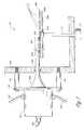
- FIG. 6An arrangement is illustrated in FIG. 6, wherein the probe assembly of FIG. 1 is shown in conjunction with a tank 200 which is open on its upper end and has a drain line 202 in its lower end.
- the probe 104is shown extending through a slot 203 into the tank above a wafer 106 mounted on a suitable support 208 including an annular rim 208 a, a plurality of spokes 208 b, joined to a hub 208 c positioned on the upper end of a shaft 210 rotated by a motor 212 .
- deionized water or other cleaning solutionis sprayed onto the upper surface of the wafer from a nozzle 214 while the probe 104 is being acoustically energized.
- the liquidcreates a meniscus 115 between the lower portion of the probe and the adjacent upper surface of the rotating wafer. This is schematically illustrated in FIG. 7 .
- the liquidprovides a medium through which the megasonic energy is transmitted to the surface of the wafer to loosen particles. These loosened particles are flushed away by the continuously flowing spray and the rotating wafer. When the liquid flow is interrupted, a certain amount of drying action is obtained through centrifical force of the liquid off of the water.
- the probe assemblymay be conveniently mounted on a suitable support, schematically illustrated at 216 .
- the supportis capable of pivoting the assembly upwardly, as indicated by the arrow in FIG. 6, to facilitate the installation and removal of wafers.
- the slot 203may instead be formed as a hole, closed at the top, and the probe may be moved radially in and out.
- FIG. 8illustrates an alternative or addition to the arrangement of FIG. 7 wherein both the lower and upper sides of a wafer are cleaned.
- a spray nozzle 254extends through a side wall of a tank 200 and is angled upwardly slightly so that cleaning fluid may be sprayed between the spokes 208 b and onto the lower surface of a wafer 106 and is directed radially inwardly so that as the wafer rotates, the entire lower surface is sprayed with the fluid.
- the waferis subjected to megasonic energy by the probe 104 in the same manner as described above in connection with FIG. 6 .
- This agitationvibrates the wafer as well as the fluid on the lower surface of the wafer which is radially aligned with the probe as the wafer rotates.
- This agitationloosens particles on the lower surface of the wafer, and the particles are flushed away with the fluid which falls or drips from the lower surface of the wafer.
- the probe assembly of FIG. 1is shown mounted to a wall of a tank 300 .
- the probe 104extends generally horizontally through central openings in a plurality of vertically orientated substrates such as “compact discs” 302 .
- the discsmay be mounted in a cassette immersed in the tank with the holes in the discs aligned with the probe.
- the cassette carrying the discscan then be moved laterally so that the probe extends through the holes in the discs, without actually contacting the discs.
- the tankis filled with liquid, such as deionized water to completely cover the discs.
- the probeis then vibrated by megasonic energy in the manner described above in connection with FIG. 1 .
- the agitation produced by the probeis transmitted into the cleaning liquid between the discs to loosen particles on the surfaces of the discs.
- the energypropagates radially outward from the probe such that both sides of each disc are exposed to such energy.
- Cleaning liquidmay be introduced into the container in continuous flow and allowed to overflow the upper end of the container to carry away loosened particles.
- a small cap 306is positioned on the tip of the probe with the cap containing an air space 308 between two glass walls 306 a and 306 b, as shown in FIG. 9 a. Since megasonic energy does not travel through ambient air to any significant degree, the cap prevents the loss of energy through the end of the probe.
- An alternative cap 310 shown in FIG. 9 bemploys a short section of glass tubing 212 attached to the end of the probe. As seen, the outer diameter of the tube is equal to the outer diameter of the probe, and the outer end of the tube spaced from the probe is closed by a disc 314 .
- FIG. 10illustrates another embodiment of the probe of the invention.
- a probe assembly 400is shown which is similar to the assembly of FIG. 1 except that the probe 404 is much shorter than the probe 104 in FIG. 1 .
- the assembly 400is oriented with the probe extending generally vertically, generally perpendicular to the surface of the horizontal wafer 106 .
- Cleaning fluidis applied to the upper surface of the wafer, and the lower tip of the probe is in contact with this fluid. Consequently, megasonic energy is transmitted through this medium onto the surface of the wafer causing loosening of particles. Since the sides of the probe are not exposed to this medium, there is no appreciable megasonic energy transmitted from the vertical sides of the probe. Instead, such megasonic energy is concentrated into the tip.
- the tipcan be moved radially with respect to the wafer as the wafer rotates so as to apply megasonic energy to the entire surface of the wafer.
- the probemay traverse the entire upper surface. Any suitable support 410 containing a mechanism to provide the desired movement may be employed.
- the preferred form of the probe assemblyincludes a probe made of inert material such as quartz and a heat transfer member coupled to the rear of the probe made of a good heat conducting material such as aluminum. Since it is the cylindrical portion of the probe which is in contact with the cleaning fluid and is positioned adjacent the wafer, an alternative arrangement could be devised wherein a forward portion, such as section 104 a in FIG. 1 could be made of the inert material and the rear portion 104 b could be made of aluminum and hence could be made as one piece with the heat transfer member 134 . This of course means that the joint between the two components would be at the rear of the cylindrical portion 104 a. While such a bonding area would not be as strong as the arrangement illustrated in FIG. 1, it may be useful in certain situations.
- the entire probecould be made of aluminum or other such material.
- the heat transfer membercould then be made as a one-piece unit with the probe.
- fluid inletcould be located in the side of the large diameter end of the probe and an outlet can be located in the end face of the small diameter probe end. The fluid would also serve as a coolant to cool the transducer, particularly if dry ice snow were employed.
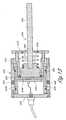
- FIG. 12has a number of similarities to the other embodiments, but has some important distinctions. That arrangement includes a cup-shaped housing 520 similar to the housing 120 in FIG. 2, but inverted with respect to the housing 120 .
- the housing 520includes a closed end wall 520 a having a surface 520 b facing the interior of the housing 520 and having an exterior surface 520 c facing away from the housing. Coupled to the interior end wall surface 520 b is a disc-shaped transducer 540 analogous to the transducer 140 referred to above in connection with FIGS. 2 and 3.
- the transducer 540is preferably bonded to the wall surface 520 b in the same manner mentioned above in connection with FIGS. 2 and 3.
- the large end 504 b of a probe 504is acoustically coupled to the housing end wall exterior surface 520 c.
- the acoustic couplingis accomplished by the use of a coil spring 543 surrounding the probe 504 and reacting against the spring retainer plate 518 to press the large end 504 b of the probe towards the housing end wall 520 a.
- a screen 141together with an appropriate viscous material, is sandwiched between the large end of the probe and the end wall 520 a.
- the coil spring adjacent the large end of the probehas a sleeve or sleeve portions 544 made of a material which will not damage the probe.
- the O-ringis held in place and compressed against the end wall 520 a and the probe by a retainer ring 519 having a surface 519 a which presses against the O-ring.
- the O-ringthus prevents the escape of the viscous material from between the probe and the housing end wall, and centers the probe.
- the retainer ringis attached to the housing by a plurality of bolts 525 which extend through the retainer ring and thread into the housing.
- the spring 543is captured and compressed by a reaction plate 518 which surrounds the probe and is attached to the housing by a plurality of fasteners 528 which thread into the retainer ring 519 and are spaced from it by sleeves 516 surrounding the fasteners 528 .
- the fasteners 525 and 528are all shown in the same plane in FIG. 12 .
- the fasteners 528would preferably be on the same bolt hole diameter as the fasteners 525 , and they of course would be spaced with respect to the fasteners 525 .
- the fastenerswould not necessarily be spaced 180° apart as illustrated, but would be spaced in whatever manner is practical.
- annular heat transfer member 534Positioned within the cup-shaped housing 520 is an annular heat transfer member 534 which has an external diameter sized to fit snugly within the housing 520 .
- An annular groove 536 in the exterior of the heat transfer member 534creates a liquid cooling channel in combination with the inner surface of the housing 520 .
- a pair of O-rings 537 that fit within annular grooves in the heat transfer memberseal the coolant channel 536 so that the remainder of the interior of the housing is sealed from the liquid. This prevents interference with the electrical energy being supplied to the transducer. Further, transducer vibration energy is not dissipated into the interior of the housing, but instead is transmitted into the housing end wall 520 a and into the probe 504 .
- the heat transfer member 534is axially captured within the housing by means of an annular shoulder 520 d and by a housing end plate 560 .
- a plurality of fasteners 528connect the plate 560 to the housing.
- a liquid coolant inlet 562 ais mounted in an opening in the end plate 560 and threads into a passage 519 in the heat transfer member that extends axially and then radially into the annular channel 536 .
- a similar outlet fitting 562 bmounts in the end plate 560 diametrically opposed from the 562 a fitting, and threads into another passage 519 that extends axially and radially into the channel 536 .
- a plurality of axially extending bores 563are also formed in the heat transfer member 534 , aligned with gas inlets 561 formed in the plate 560 .
- the inlets 561 and bores 563are shown in the same plane with the passages 519 for convenience.
- the bores 563would preferably not be in the same plane as the passages 519 , and instead would be circumferentially offset, and could also be formed in the same circle around the center of the heat transfer member 534 .
- the inlets 561 through the end plate 560 for the fittings 562 a and 562 bwould likewise be moved to be aligned with the passages 563 .
- the electrical connection for the transducer 540is illustrated by the wire 554 , although the more complete connection would be as shown in FIG. 3 . That wire extends through a fitting 528 which in turn is connected to an electrical cord 526 .
- FIG. 12there are a number of advantages to the embodiment illustrated in FIG. 12 .
- By coupling the transducer and the probe to the housing end wallmore energy may be transmitted to the probe than with the corresponding amount of power applied to the transducer in the arrangement of FIG. 2, inasmuch as the housing end wall has less mass than the mass of the heat transfer member 140 shown in FIG. 3 . While some energy is lost into the other portions of the housing, there is a net increase in efficiency.
- the relatively thin end wallhas fewer internal energy reflections than a thicker wall simply because of the reduced mass.
- the housing end walldoes not have the discontinuities caused by the grooves in the heat transfer member of FIG. 2, or by the O-ring in the grooves.
- the heat generated by the transducercan be readily dissipated with the arrangement of FIG. 12 .
- the heat transfer member 534can be made of the desired axial length without concern for its mass because it is not to be vibrated as in the arrangement of FIG. 2 .
- the cooling liquidenters through the fitting 562 a, flows axially and then radially into the channel 536 , where it splits into two branch flows in opposite directions, that meet on the other side of the heat transfer member and flow out the fitting 562 b.
- cooling gassuch as nitrogen can be connected to one or more of the bores 563 in the heat transfer member and into the central area of the housing. The gas is exhausted through one of the bores 563 leading to a second outlet 561 b.
- Two passages 563are illustrated in FIG. 12 . Three are preferable, but more or less may be utilized if desired.
- boltsmay be threaded into the bores 563 to assist in withdrawing the heat transfer member from the housing.
- the assembly illustrated in FIG. 12may be used in connection with a wall mounted arrangement such as that shown in FIG. 1, or may be used with a system such as that as illustrated in FIG. 8, wherein the probe assembly is moved into or out of position with respect to a wafer to facilitate insertion and removal of wafers.
- a probemay be moved out of the way by mounting it on a bracket that will pivot it in the direction of the arrow 218 shown in FIG. 8, or it may be on a track arrangement (not shown) which will move it radially inwardly and outwardly with respect to the wafer and its supporting member.
- the assembly of FIG. 12may be mounted to these other structures in any suitable fashion, such as by making connections to the end plate 560 .
- FIG. 13includes a generally tubular or cylindrical housing 620 .
- a heat transfer member 634Positioned within the housing is a heat transfer member 634 having an outer annular wall 634 a which fits snugly within a surrounding annular wall of the housing 620 .
- the heat transfer member 634has an annular channel 636 formed in its outer surface that faces the surrounding housing wall to form a coolant passage.
- a coolant inlet 644 in the housing wallleads into the passage and an outlet 646 on the opposite side of the housing leads out of the passage.
- the heat transfer member 634has somewhat of an H-shaped cross section created by a central disc-shaped wall 634 b integrally formed with the surrounding annular wall 634 a. As seen, the central wall 634 b is relatively thin and it is radially aligned with the surrounding coolant passage 636 .
- the heat transfer memberis axially captured within the housing by an internal shoulder on one end of the housing and by an end plate 660 on the other end.
- a piezoelectric transducer 640is acoustically coupled to one side of the central wall 634 b, such as in the same manner discussed above in connection with the other embodiments.
- a probe 604is acoustically coupled to the other side of the central wall 634 b. Again, this may be done in various ways, such as the screen and grease technique discussed above.
- An O-ring 621surrounds the base of the probe and is compressed against the probe and the central wall 634 b by a cylindrical portion of an end member 619 having a flange attached to the end of the housing 620 . The O-ring confines the coupling grease and helps center the probe 604 .
- the probeis pressed against the central wall 634 b by a spring 643 compressed between an annular spring retainer plate 18 and the probe 604 .
- the housing and heat transfer member illustrated in FIG. 13may be used with the probes illustrated in the above-mentioned embodiments, but it is illustrated in FIG. 13 with an alternate probe construction. Instead of having the probe made of one piece, it is formed in separate portions including a base 605 adjacent the central wall 634 b of the heat transfer member, and an elongated cleaning rod 606 .
- the base 605has a cylindrical exterior with a reduced diameter portion 605 a on the end spaced from the central wall 634 b.
- One end of the spring 643surrounds the base portion 605 a and engages the shoulder on the base 605 adjacent the portion 605 a.
- the rod 606 of the probefits within a central socket formed in the base 605 . It is bonded to the base by a suitable adhesive which will not interfere with the transmission of the megasonic energy provided by the transducer 640 and propagated through the central wall 634 b and the base 605 of the probe.
- the base 605can have a frusto-conical configuration just as the rear portion of the probe in FIG. 12, and the spring 643 could then engage the sloping side wall of such shape rather than having the step configuration shown in FIG. 13 .
- the rod 606could have a tapered end and the spring could engage it as suggested by FIG. 12 .
- a primary purpose of having a probe made of two different portionsis that one portion can be made of a different material from the other.
- the base 605can be utilized in any cleaning operation since it does not contact the cleaning solution; however, the rod 606 must be compatible with the cleaning solution.
- the cleaning solutionis compatible with quartz, a one-piece arrangement such as that illustrated in FIG. 1 or FIG. 12 could be conveniently utilized.
- the cleaning solutionis not compatible with quartz, such as a solution containing hydrofluoric acid
- a material for the rodis needed that is compatible, such as vitreous carbon
- the basecan be quartz. It is currently difficult to obtain vitreous carbon in a shape such as that illustrated in FIG. 12 .
- a straight cylindrical rodis more readily available.
- any other desirable combination of suitable materials for the rod and the basemay be employed.
- the arrangement of FIG. 13is particularly desirable from the standpoint that the transmission of megasonic energy is efficient through the thin wall portion of the heat exchange member, but yet the heat exchange process is very efficient. This is because the transducer, which is the heat generator, is in direct contact with the heat transfer member, which is in direct contact with the coolant passage 636 . It should be recognized that other heat transfer arrangements may be employed. For example, if the heat transfer member has sufficient surface area, it might be possible to have it air-cooled rather than liquid-cooled. It should also be recognized that various other modifications of that type may be made to the embodiments illustrated without departing from the scope of the invention, and all such changes are intended to fall within the scope of the invention, as defined by the appended claims.
Landscapes
- Engineering & Computer Science (AREA)
- Physics & Mathematics (AREA)
- Condensed Matter Physics & Semiconductors (AREA)
- General Physics & Mathematics (AREA)
- Manufacturing & Machinery (AREA)
- Computer Hardware Design (AREA)
- Microelectronics & Electronic Packaging (AREA)
- Power Engineering (AREA)
- Mechanical Engineering (AREA)
- Cleaning Or Drying Semiconductors (AREA)
- Cleaning By Liquid Or Steam (AREA)
Abstract
Description
Claims (35)
Priority Applications (10)
| Application Number | Priority Date | Filing Date | Title |
|---|---|---|---|
| US09/953,504US6463938B2 (en) | 1996-09-30 | 2001-09-13 | Wafer cleaning method |
| US10/243,486US6684891B2 (en) | 1996-09-30 | 2002-09-12 | Wafer cleaning |
| US10/243,463US6681782B2 (en) | 1996-09-30 | 2002-09-12 | Wafer cleaning |
| US10/726,774US7117876B2 (en) | 1996-09-30 | 2003-12-03 | Method of cleaning a side of a thin flat substrate by applying sonic energy to the opposite side of the substrate |
| US11/375,907US7268469B2 (en) | 1996-09-30 | 2006-03-15 | Transducer assembly for megasonic processing of an article and apparatus utilizing the same |
| US11/386,634US7211932B2 (en) | 1996-09-30 | 2006-03-22 | Apparatus for megasonic processing of an article |
| US11/839,885US7518288B2 (en) | 1996-09-30 | 2007-08-16 | System for megasonic processing of an article |
| US12/399,185US20090165831A1 (en) | 1996-09-30 | 2009-03-06 | System for megasonic processing of an article |
| US13/270,849US8257505B2 (en) | 1996-09-30 | 2011-10-11 | Method for megasonic processing of an article |
| US13/603,082US8771427B2 (en) | 1996-09-30 | 2012-09-04 | Method of manufacturing integrated circuit devices |
Applications Claiming Priority (4)
| Application Number | Priority Date | Filing Date | Title |
|---|---|---|---|
| US08/724,518US6039059A (en) | 1996-09-30 | 1996-09-30 | Wafer cleaning system |
| US09/057,182US6140744A (en) | 1996-09-30 | 1998-04-08 | Wafer cleaning system |
| US09/643,328US6295999B1 (en) | 1996-09-30 | 2000-08-22 | Wafer cleaning method |
| US09/953,504US6463938B2 (en) | 1996-09-30 | 2001-09-13 | Wafer cleaning method |
Related Parent Applications (1)
| Application Number | Title | Priority Date | Filing Date |
|---|---|---|---|
| US09/643,328ContinuationUS6295999B1 (en) | 1996-09-30 | 2000-08-22 | Wafer cleaning method |
Related Child Applications (3)
| Application Number | Title | Priority Date | Filing Date |
|---|---|---|---|
| US10/243,463ContinuationUS6681782B2 (en) | 1996-09-30 | 2002-09-12 | Wafer cleaning |
| US10/243,486ContinuationUS6684891B2 (en) | 1996-09-30 | 2002-09-12 | Wafer cleaning |
| US10/243,468ContinuationUS6875595B2 (en) | 2001-09-13 | 2002-09-13 | Nematode fatty acid desaturase-like sequences |
Publications (2)
| Publication Number | Publication Date |
|---|---|
| US20020011256A1 US20020011256A1 (en) | 2002-01-31 |
| US6463938B2true US6463938B2 (en) | 2002-10-15 |
Family
ID=24910738
Family Applications (13)
| Application Number | Title | Priority Date | Filing Date |
|---|---|---|---|
| US08/724,518Expired - LifetimeUS6039059A (en) | 1996-09-30 | 1996-09-30 | Wafer cleaning system |
| US09/057,182Expired - LifetimeUS6140744A (en) | 1996-09-30 | 1998-04-08 | Wafer cleaning system |
| US09/643,328Expired - LifetimeUS6295999B1 (en) | 1996-09-30 | 2000-08-22 | Wafer cleaning method |
| US09/953,504Expired - LifetimeUS6463938B2 (en) | 1996-09-30 | 2001-09-13 | Wafer cleaning method |
| US10/243,486Expired - LifetimeUS6684891B2 (en) | 1996-09-30 | 2002-09-12 | Wafer cleaning |
| US10/243,463Expired - LifetimeUS6681782B2 (en) | 1996-09-30 | 2002-09-12 | Wafer cleaning |
| US10/726,774Expired - Fee RelatedUS7117876B2 (en) | 1996-09-30 | 2003-12-03 | Method of cleaning a side of a thin flat substrate by applying sonic energy to the opposite side of the substrate |
| US11/375,907Expired - Fee RelatedUS7268469B2 (en) | 1996-09-30 | 2006-03-15 | Transducer assembly for megasonic processing of an article and apparatus utilizing the same |
| US11/386,634Expired - Fee RelatedUS7211932B2 (en) | 1996-09-30 | 2006-03-22 | Apparatus for megasonic processing of an article |
| US11/839,885Expired - Fee RelatedUS7518288B2 (en) | 1996-09-30 | 2007-08-16 | System for megasonic processing of an article |
| US12/399,185AbandonedUS20090165831A1 (en) | 1996-09-30 | 2009-03-06 | System for megasonic processing of an article |
| US13/270,849Expired - Fee RelatedUS8257505B2 (en) | 1996-09-30 | 2011-10-11 | Method for megasonic processing of an article |
| US13/603,082Expired - Fee RelatedUS8771427B2 (en) | 1996-09-30 | 2012-09-04 | Method of manufacturing integrated circuit devices |
Family Applications Before (3)
| Application Number | Title | Priority Date | Filing Date |
|---|---|---|---|
| US08/724,518Expired - LifetimeUS6039059A (en) | 1996-09-30 | 1996-09-30 | Wafer cleaning system |
| US09/057,182Expired - LifetimeUS6140744A (en) | 1996-09-30 | 1998-04-08 | Wafer cleaning system |
| US09/643,328Expired - LifetimeUS6295999B1 (en) | 1996-09-30 | 2000-08-22 | Wafer cleaning method |
Family Applications After (9)
| Application Number | Title | Priority Date | Filing Date |
|---|---|---|---|
| US10/243,486Expired - LifetimeUS6684891B2 (en) | 1996-09-30 | 2002-09-12 | Wafer cleaning |
| US10/243,463Expired - LifetimeUS6681782B2 (en) | 1996-09-30 | 2002-09-12 | Wafer cleaning |
| US10/726,774Expired - Fee RelatedUS7117876B2 (en) | 1996-09-30 | 2003-12-03 | Method of cleaning a side of a thin flat substrate by applying sonic energy to the opposite side of the substrate |
| US11/375,907Expired - Fee RelatedUS7268469B2 (en) | 1996-09-30 | 2006-03-15 | Transducer assembly for megasonic processing of an article and apparatus utilizing the same |
| US11/386,634Expired - Fee RelatedUS7211932B2 (en) | 1996-09-30 | 2006-03-22 | Apparatus for megasonic processing of an article |
| US11/839,885Expired - Fee RelatedUS7518288B2 (en) | 1996-09-30 | 2007-08-16 | System for megasonic processing of an article |
| US12/399,185AbandonedUS20090165831A1 (en) | 1996-09-30 | 2009-03-06 | System for megasonic processing of an article |
| US13/270,849Expired - Fee RelatedUS8257505B2 (en) | 1996-09-30 | 2011-10-11 | Method for megasonic processing of an article |
| US13/603,082Expired - Fee RelatedUS8771427B2 (en) | 1996-09-30 | 2012-09-04 | Method of manufacturing integrated circuit devices |
Country Status (6)
| Country | Link |
|---|---|
| US (13) | US6039059A (en) |
| EP (1) | EP0938745B1 (en) |
| JP (1) | JP3493492B2 (en) |
| KR (2) | KR100392242B1 (en) |
| DE (1) | DE69711210T2 (en) |
| WO (1) | WO1998014985A1 (en) |
Cited By (18)
| Publication number | Priority date | Publication date | Assignee | Title |
|---|---|---|---|---|
| US20020185153A1 (en)* | 2001-06-12 | 2002-12-12 | Hosack Chad M. | Stackable process chambers |
| US20030010356A1 (en)* | 2001-07-09 | 2003-01-16 | Birol Kuyel | Single wafer megasonic cleaner method, system, and apparatus |
| US6681782B2 (en)* | 1996-09-30 | 2004-01-27 | Verteq, Inc. | Wafer cleaning |
| US20050072525A1 (en)* | 2003-10-06 | 2005-04-07 | Applied Materials, Inc. | Apparatus to improve wafer temperature uniformity for face-up wet processing |
| US20050072526A1 (en)* | 2003-10-06 | 2005-04-07 | Applied Materials, Inc. | Heating apparatus to heat wafers using water and plate with turbolators |
| US20050160990A1 (en)* | 2004-01-26 | 2005-07-28 | Dmitry Lubomirsky | Apparatus for electroless deposition of metals onto semiconductor substrates |
| US20050173253A1 (en)* | 2004-02-05 | 2005-08-11 | Applied Materials, Inc. | Method and apparatus for infilm defect reduction for electrochemical copper deposition |
| US20050284509A1 (en)* | 2004-06-24 | 2005-12-29 | Naoaki Sakurai | Ultrasonic cleaning apparatus |
| US20060016458A1 (en)* | 2004-07-09 | 2006-01-26 | Richard Novak | Reduced pressure irradiation processing method and apparatus |
| US20060042671A1 (en)* | 2003-10-24 | 2006-03-02 | Connelly Rowan T | Ultrasonic optical cleaning system |
| US7238085B2 (en) | 2003-06-06 | 2007-07-03 | P.C.T. Systems, Inc. | Method and apparatus to process substrates with megasonic energy |
| US20070169800A1 (en)* | 2006-01-20 | 2007-07-26 | Pejman Fani | Acoustic energy system, method and apparatus for processing flat articles |
| US20070170812A1 (en)* | 2006-01-20 | 2007-07-26 | Pejman Fani | System apparatus and methods for processing substrates using acoustic energy |
| US20090050175A1 (en)* | 2007-08-21 | 2009-02-26 | Takayoshi Tanaka | Substrate cleaning apparatus and substrate cleaning method |
| US7654221B2 (en) | 2003-10-06 | 2010-02-02 | Applied Materials, Inc. | Apparatus for electroless deposition of metals onto semiconductor substrates |
| US7827930B2 (en) | 2004-01-26 | 2010-11-09 | Applied Materials, Inc. | Apparatus for electroless deposition of metals onto semiconductor substrates |
| US9049520B2 (en) | 2006-01-20 | 2015-06-02 | Akrion Systems Llc | Composite transducer apparatus and system for processing a substrate and method of constructing the same |
| US9987666B2 (en) | 2006-01-20 | 2018-06-05 | Naura Akrion Inc. | Composite transducer apparatus and system for processing a substrate and method of constructing the same |
Families Citing this family (136)
| Publication number | Priority date | Publication date | Assignee | Title |
|---|---|---|---|---|
| US20050194356A1 (en)* | 1997-05-09 | 2005-09-08 | Semitool, Inc. | Removing photoresist from a workpiece using water and ozone and a photoresist penetrating additive |
| US20050034745A1 (en)* | 1997-05-09 | 2005-02-17 | Semitool, Inc. | Processing a workpiece with ozone and a halogenated additive |
| US7163588B2 (en)* | 1997-05-09 | 2007-01-16 | Semitool, Inc. | Processing a workpiece using water, a base, and ozone |
| US7416611B2 (en)* | 1997-05-09 | 2008-08-26 | Semitool, Inc. | Process and apparatus for treating a workpiece with gases |
| US20020157686A1 (en)* | 1997-05-09 | 2002-10-31 | Semitool, Inc. | Process and apparatus for treating a workpiece such as a semiconductor wafer |
| US6701941B1 (en)* | 1997-05-09 | 2004-03-09 | Semitool, Inc. | Method for treating the surface of a workpiece |
| US20020066464A1 (en)* | 1997-05-09 | 2002-06-06 | Semitool, Inc. | Processing a workpiece using ozone and sonic energy |
| US6070284A (en) | 1998-02-04 | 2000-06-06 | Silikinetic Technology, Inc. | Wafer cleaning method and system |
| US6376444B1 (en) | 1998-02-20 | 2002-04-23 | Procter & Gamble Company | Garment stain removal product which uses sonic or ultrasonic waves |
| EP1056829B1 (en) | 1998-02-20 | 2004-05-12 | The Procter & Gamble Company | Carpet stain removal product which uses sonic or ultrasonic waves |
| US6946399B1 (en)* | 1998-10-05 | 2005-09-20 | Lorimer D Arcy Harold | Cleaning system method and apparatus for the manufacture of integrated cicuits |
| ES2226491T3 (en) | 1998-11-16 | 2005-03-16 | THE PROCTER & GAMBLE COMPANY | CLEANING PRODUCT USING SONIC OR ULTRASONIC WAVES. |
| US6617760B1 (en)* | 1999-03-05 | 2003-09-09 | Cybersonics, Inc. | Ultrasonic resonator |
| DE19916345A1 (en)* | 1999-04-12 | 2000-10-26 | Steag Electronic Systems Gmbh | Method and device for cleaning substrates |
| WO2001000336A1 (en)* | 1999-06-24 | 2001-01-04 | Sumitomo Heavy Industries, Ltd. | Method and device for washing by fluid spraying |
| US6222305B1 (en) | 1999-08-27 | 2001-04-24 | Product Systems Incorporated | Chemically inert megasonic transducer system |
| US6904921B2 (en)* | 2001-04-23 | 2005-06-14 | Product Systems Incorporated | Indium or tin bonded megasonic transducer systems |
| US6228563B1 (en) | 1999-09-17 | 2001-05-08 | Gasonics International Corporation | Method and apparatus for removing post-etch residues and other adherent matrices |
| AU1613601A (en)* | 1999-11-16 | 2001-05-30 | Procter & Gamble Company, The | Cleaning process which uses ultrasonic waves |
| JP3998386B2 (en)* | 2000-01-26 | 2007-10-24 | 三菱電機株式会社 | Liquid crystal display device manufacturing apparatus and liquid crystal display device manufacturing method |
| US6539952B2 (en) | 2000-04-25 | 2003-04-01 | Solid State Equipment Corp. | Megasonic treatment apparatus |
| JP2001313317A (en)* | 2000-04-28 | 2001-11-09 | Ando Electric Co Ltd | Method and device for cleaning probe |
| AU2001270205A1 (en) | 2000-06-26 | 2002-01-08 | Applied Materials, Inc. | Method and apparatus for wafer cleaning |
| US7451774B2 (en) | 2000-06-26 | 2008-11-18 | Applied Materials, Inc. | Method and apparatus for wafer cleaning |
| US7105985B2 (en)* | 2001-04-23 | 2006-09-12 | Product Systems Incorporated | Megasonic transducer with focused energy resonator |
| US7100304B2 (en)* | 2001-06-12 | 2006-09-05 | Akrion Technologies, Inc. | Megasonic cleaner and dryer |
| JP2003037093A (en)* | 2001-07-06 | 2003-02-07 | Pacific Internatl Stg Inc | Ultrasonic vibrator and ultrasonic cleaning apparatus having the same |
| US6684890B2 (en) | 2001-07-16 | 2004-02-03 | Verteq, Inc. | Megasonic cleaner probe system with gasified fluid |
| US20050087209A1 (en)* | 2001-07-16 | 2005-04-28 | Nicolosi Thomas J.Jr. | Megasonic processing system with gasified fluid |
| US7156111B2 (en)* | 2001-07-16 | 2007-01-02 | Akrion Technologies, Inc | Megasonic cleaning using supersaturated cleaning solution |
| US6679272B2 (en)* | 2001-08-03 | 2004-01-20 | Verteq, Inc. | Megasonic probe energy attenuator |
| KR100741029B1 (en)* | 2001-08-08 | 2007-07-19 | 씨앤지하이테크 주식회사 | Megasonic energy generator |
| US7004182B2 (en) | 2001-10-18 | 2006-02-28 | The Procter & Gamble Company | Enhanced ultrasonic cleaning devices |
| AU2002364693A1 (en)* | 2001-11-02 | 2003-06-10 | Product Systems Incorporated | Radial power megasonic transducer |
| KR100445259B1 (en)* | 2001-11-27 | 2004-08-21 | 삼성전자주식회사 | Cleaning method and cleaning apparatus for performing the same |
| US6875284B2 (en)* | 2002-01-23 | 2005-04-05 | Semitool, Inc. | Side-specific cleaning method and apparatus |
| US7287537B2 (en)* | 2002-01-29 | 2007-10-30 | Akrion Technologies, Inc. | Megasonic probe energy director |
| KR100493016B1 (en)* | 2002-03-23 | 2005-06-07 | 삼성전자주식회사 | Megasonic cleaning apparatus for fabricating semiconductor device |
| US6845778B2 (en) | 2002-03-29 | 2005-01-25 | Lam Research Corporation | In-situ local heating using megasonic transducer resonator |
| KR100459710B1 (en)* | 2002-04-15 | 2004-12-04 | 삼성전자주식회사 | Apparatus of cleaning wafer |
| US6848455B1 (en)* | 2002-04-22 | 2005-02-01 | Novellus Systems, Inc. | Method and apparatus for removing photoresist and post-etch residue from semiconductor substrates by in-situ generation of oxidizing species |
| US6843257B2 (en)* | 2002-04-25 | 2005-01-18 | Samsung Electronics Co., Ltd. | Wafer cleaning system |
| US7185661B2 (en)* | 2002-05-06 | 2007-03-06 | Akrion Technologies, Inc. | Reciprocating megasonic probe |
| US20040031167A1 (en) | 2002-06-13 | 2004-02-19 | Stein Nathan D. | Single wafer method and apparatus for drying semiconductor substrates using an inert gas air-knife |
| KR100481158B1 (en)* | 2002-07-03 | 2005-04-07 | (주)케이.씨.텍 | Apparatus for treating a wafer |
| KR100468110B1 (en)* | 2002-07-12 | 2005-01-26 | 삼성전자주식회사 | Apparatus for treating a wafer |
| CN1271683C (en)* | 2002-07-25 | 2006-08-23 | 松下电器产业株式会社 | A kind of substrate coating method |
| US6908567B2 (en)* | 2002-07-30 | 2005-06-21 | Applied Materials Israel, Ltd. | Contaminant removal by laser-accelerated fluid |
| KR100473475B1 (en)* | 2002-08-09 | 2005-03-10 | 삼성전자주식회사 | Apparatus for cleaning a substrate |
| US20040029494A1 (en)* | 2002-08-09 | 2004-02-12 | Souvik Banerjee | Post-CMP cleaning of semiconductor wafer surfaces using a combination of aqueous and CO2 based cryogenic cleaning techniques |
| TWI230397B (en) | 2002-09-30 | 2005-04-01 | Lam Res Corp | Method and apparatus for drying semiconductor wafer surfaces using a plurality of inlets and outlets held in close proximity to the wafer surfaces |
| US7198055B2 (en)* | 2002-09-30 | 2007-04-03 | Lam Research Corporation | Meniscus, vacuum, IPA vapor, drying manifold |
| US7524771B2 (en)* | 2002-10-29 | 2009-04-28 | Dainippon Screen Mfg. Co., Ltd. | Substrate processing method using alkaline solution and acid solution |
| CN1307716C (en)* | 2002-12-06 | 2007-03-28 | 诺亚公司 | Multidirectional liquid storage slot heat conducting apparatus and method |
| US7306002B2 (en)* | 2003-01-04 | 2007-12-11 | Yong Bae Kim | System and method for wet cleaning a semiconductor wafer |
| US6864458B2 (en)* | 2003-01-21 | 2005-03-08 | Applied Materials, Inc. | Iced film substrate cleaning |
| KR100526192B1 (en)* | 2003-05-28 | 2005-11-03 | 삼성전자주식회사 | Apparatus and Method For Cleaning Wafer |
| AU2003903659A0 (en)* | 2003-07-16 | 2003-07-31 | Soniclean Pty Ltd | An apparatus and method of ultrasonic cleaning |
| KR100979719B1 (en)* | 2003-07-18 | 2010-09-03 | 매그나칩 반도체 유한회사 | Manufacturing Method of Semiconductor Device |
| JP4241302B2 (en)* | 2003-09-30 | 2009-03-18 | 株式会社ルネサステクノロジ | Manufacturing method of semiconductor device |
| US6959589B1 (en)* | 2003-10-03 | 2005-11-01 | The United States Of America As Represented By The United States Department Of Energy | Ultrasound analysis of slurries |
| NZ543156A (en)* | 2003-10-22 | 2008-09-26 | Soniclean Pty Ltd | An apparatus and method for cleaning and recycling water used in cleaning of barrels |
| US7516507B1 (en) | 2003-11-10 | 2009-04-14 | Xyratex Technologies, Ltd. | Integrated megasonic cascade scrubber module and process |
| US20050098198A1 (en)* | 2003-11-10 | 2005-05-12 | Reg Yang | Washing device for packaging the image |
| DE10361075A1 (en)* | 2003-12-22 | 2005-07-28 | Pac Tech - Packaging Technologies Gmbh | Method and apparatus for drying circuit substrates |
| US7439654B2 (en)* | 2004-02-24 | 2008-10-21 | Air Products And Chemicals, Inc. | Transmission of ultrasonic energy into pressurized fluids |
| US7084553B2 (en)* | 2004-03-04 | 2006-08-01 | Ludwiczak Damian R | Vibrating debris remover |
| CN1707746A (en)* | 2004-06-10 | 2005-12-14 | 中芯国际集成电路制造(上海)有限公司 | Method for processing optical mask of semiconductor device |
| WO2006010997A1 (en)* | 2004-07-16 | 2006-02-02 | Darren Miles Bates | An apparatus and method of ultrasonic cleaning |
| US20060027248A1 (en)* | 2004-08-09 | 2006-02-09 | Applied Materials, Inc. | Megasonic cleaning with minimized interference |
| US7718009B2 (en) | 2004-08-30 | 2010-05-18 | Applied Materials, Inc. | Cleaning submicron structures on a semiconductor wafer surface |
| CN101124053B (en)* | 2004-09-15 | 2012-05-23 | 艾奎昂技术股份有限公司 | System and method of powering a sonic energy source and use of the same to process substrates |
| KR100578139B1 (en) | 2004-10-05 | 2006-05-10 | 삼성전자주식회사 | Cleaning probes and megasonic cleaning equipment having the same |
| KR100598112B1 (en)* | 2004-12-20 | 2006-07-07 | 삼성전자주식회사 | Ultrasonic Cleaning Apparatus and Cleaning Method With Double Cleaning Probe |
| JP4407944B2 (en) | 2004-12-21 | 2010-02-03 | 大日本スクリーン製造株式会社 | Substrate processing apparatus and substrate processing method |
| US20090126760A1 (en)* | 2005-01-12 | 2009-05-21 | Boc, Inc. | System for cleaning a surface using crogenic aerosol and fluid reactant |
| US10179351B2 (en) | 2005-02-07 | 2019-01-15 | Planar Semiconductor, Inc. | Method and apparatus for cleaning flat objects with pulsed liquid jet |
| US9799536B2 (en)* | 2005-02-07 | 2017-10-24 | Planar Semiconductor, Inc. | Apparatus and method for cleaning flat objects in a vertical orientation with pulsed liquid jet |
| DE102005007056A1 (en)* | 2005-02-15 | 2006-08-24 | Dieter Weber | Ultrasonic rod transducers |
| US20060260638A1 (en)* | 2005-03-08 | 2006-11-23 | Pejman Fani | Method and system for processing substrates with sonic energy that reduces or eliminates damage to semiconductor devices |
| US7744016B2 (en)* | 2005-05-26 | 2010-06-29 | Honda Electronics Co., Ltd. | Ultrasonic washing apparatus |
| TW200738356A (en)* | 2005-06-15 | 2007-10-16 | Akrion Inc | System and method of processing substrates using sonic energy having cavitation control |
| RU2303496C2 (en)* | 2005-06-15 | 2007-07-27 | Закрытое Акционерное Общество Научно-Производственное Предприятие "Нефтетрубосервис" | Device for ultrasonic treatment of article surface |
| US20070084481A1 (en)* | 2005-10-07 | 2007-04-19 | Franklin Cole S | System and method of cleaning substrates using a subambient process solution |
| JP4527670B2 (en)* | 2006-01-25 | 2010-08-18 | 東京エレクトロン株式会社 | Heat treatment apparatus, heat treatment method, control program, and computer-readable storage medium |
| US20100200021A1 (en)* | 2006-02-17 | 2010-08-12 | Nils Adey | Slide Conditioning Systems and Methods |
| DE102006033372B4 (en)* | 2006-02-17 | 2010-04-29 | Fraunhofer-Gesellschaft zur Förderung der angewandten Forschung e.V. | Ultrasonic actuator for cleaning objects |
| WO2008008921A2 (en)* | 2006-07-12 | 2008-01-17 | Akrion Technologies, Inc. | Tranducer assembly incorporating a transmitter having through holes, and method of cleaning |
| TWI352628B (en)* | 2006-07-21 | 2011-11-21 | Akrion Technologies Inc | Nozzle for use in the megasonic cleaning of substr |
| TW200817105A (en)* | 2006-08-18 | 2008-04-16 | Akrion Technologies Inc | System and method for processing a substrate utilizing a gas stream for particle removal |
| KR100829923B1 (en)* | 2006-08-30 | 2008-05-16 | 세메스 주식회사 | Spin head and substrate processing method using same |
| KR100800174B1 (en)* | 2006-10-20 | 2008-02-01 | 한국기계연구원 | Megasonic Cleaning Module |
| US8327861B2 (en)* | 2006-12-19 | 2012-12-11 | Lam Research Corporation | Megasonic precision cleaning of semiconductor process equipment components and parts |
| US20080148595A1 (en)* | 2006-12-20 | 2008-06-26 | Lam Research Corporation | Method and apparatus for drying substrates using a surface tensions reducing gas |
| US20080166210A1 (en)* | 2007-01-05 | 2008-07-10 | Applied Materials, Inc. | Supinating cartesian robot blade |
| US7694688B2 (en) | 2007-01-05 | 2010-04-13 | Applied Materials, Inc. | Wet clean system design |
| US20080163890A1 (en)* | 2007-01-10 | 2008-07-10 | Applied Materials, Inc. | Tunable megasonics cavitation process using multiple transducers for cleaning nanometer particles without structure damage |
| JP5109376B2 (en) | 2007-01-22 | 2012-12-26 | 東京エレクトロン株式会社 | Heating device, heating method and storage medium |
| US7872400B2 (en)* | 2007-09-24 | 2011-01-18 | Dr. Hielscher Gmbh | Ultrasonic device with a disk-shaped resonator |
| JP2009081366A (en)* | 2007-09-27 | 2009-04-16 | Elpida Memory Inc | Batch processing apparatus |
| US8040022B2 (en)* | 2007-12-12 | 2011-10-18 | Aprolase Development Co., Llc | Forced vibration piezo generator and piezo actuator |
| US20100167943A1 (en)* | 2008-06-09 | 2010-07-01 | Nils Adey | System and Method for Hybridization Slide Processing |
| US20110190153A1 (en)* | 2008-06-09 | 2011-08-04 | Nils Adey | System and method for hybridization slide processing |
| JP4532580B2 (en) | 2008-08-20 | 2010-08-25 | 株式会社カイジョー | Ultrasonic cleaning equipment |
| US8702017B2 (en)* | 2008-12-16 | 2014-04-22 | Asm Assembly Automation Ltd | Nozzle device employing high frequency wave energy |
| TWI483299B (en)* | 2009-01-09 | 2015-05-01 | 盛美半導體設備(上海)有限公司 | Semiconductor cymbal cleaning method and device |
| TWI501297B (en)* | 2009-03-31 | 2015-09-21 | 盛美半導體設備(上海)有限公司 | Semiconductor cymbal cleaning method and device |
| KR20110064511A (en)* | 2009-12-08 | 2011-06-15 | 삼성메디슨 주식회사 | Ultrasonic Probe Device and Manufacturing Method Thereof |
| WO2012028696A1 (en)* | 2010-09-02 | 2012-03-08 | Dr. Hielscher Gmbh | Device and method for nebulising or atomising free-flowing media |
| US9048450B2 (en) | 2010-10-21 | 2015-06-02 | Koninklijkle Philips N.V. | OLED device with a brightness distribution controlling means |
| JP5758111B2 (en)* | 2010-12-02 | 2015-08-05 | 株式会社ディスコ | Cutting equipment |
| US8551251B2 (en) | 2011-04-28 | 2013-10-08 | Lam Research Ag | Ultrasonic treatment method and apparatus |
| US9421617B2 (en) | 2011-06-22 | 2016-08-23 | Tel Nexx, Inc. | Substrate holder |
| US8613474B2 (en) | 2011-07-06 | 2013-12-24 | Tel Nexx, Inc. | Substrate loader and unloader having a Bernoulli support |
| US8486199B2 (en) | 2011-07-22 | 2013-07-16 | Lam Research Ag | Ultrasonic cleaning method and apparatus |
| KR101308352B1 (en) | 2011-12-16 | 2013-09-17 | 주식회사 엘지실트론 | Apparatus for single wafer etching |
| WO2013093183A1 (en)* | 2011-12-21 | 2013-06-27 | Vahterus Oy | Ultrasonic cleaner for a heat exchanger |
| RU2524603C2 (en)* | 2012-06-27 | 2014-07-27 | Михаил Олегович Мамонтов | Method of surface hydrocavitation cleaning and device to this end |
| CN103776477A (en)* | 2014-01-24 | 2014-05-07 | 深圳市华星光电技术有限公司 | Swing type sensor module |
| US10688536B2 (en)* | 2014-02-24 | 2020-06-23 | The Boeing Company | System and method for surface cleaning |
| CN104894634A (en)* | 2014-03-03 | 2015-09-09 | 盛美半导体设备(上海)有限公司 | Novel electrochemical polishing device |
| CN107636799B (en) | 2015-05-20 | 2021-12-03 | 盛美半导体设备(上海)股份有限公司 | Method and apparatus for cleaning semiconductor substrate |
| WO2017125242A1 (en) | 2016-01-20 | 2017-07-27 | DUSSAULT, Donald Herbert | Method and apparatus for cleaning a disc record |
| EP3515611A4 (en) | 2016-09-19 | 2020-05-13 | ACM Research (Shanghai) Inc. | METHODS AND APPARATUS FOR CLEANING SUBSTRATES |
| JP7032815B2 (en)* | 2016-09-20 | 2022-03-09 | エーシーエム リサーチ (シャンハイ) インコーポレーテッド | Board cleaning method and cleaning equipment |
| US20180147611A1 (en)* | 2016-11-29 | 2018-05-31 | 1863815 Ontario Limited | Apparatus, System and Method for Cleaning Inner Surfaces of Tubing |
| JP6975725B2 (en)* | 2016-12-20 | 2021-12-01 | 株式会社日立ハイテク | Ultrasonic cleaner and automatic analyzer using it |
| KR20190086859A (en)* | 2018-01-15 | 2019-07-24 | 삼성전자주식회사 | Substrate Support Mechanism And Substrate Cleaning Device Including The Same |
| CN108704829A (en)* | 2018-07-18 | 2018-10-26 | 方安轩 | A kind of closed ultrasound wave vibrating bar |
| CN109326538A (en)* | 2018-09-13 | 2019-02-12 | 江西展宇新能源股份有限公司 | A wet black silicon texturing cleaning tank, a texturing machine and a wet black silicon texturing method |
| RU191310U1 (en)* | 2018-12-26 | 2019-08-01 | федеральное государственное автономное образовательное учреждение высшего образования "Московский физико-технический институт (национальный исследовательский университет)" | Device for ultrasonic cleaning of nanocalorimetric sensors |
| US12072318B2 (en)* | 2019-05-23 | 2024-08-27 | Lam Research Corporation | Chamber component cleanliness measurement system |
| ES2981230T3 (en)* | 2019-11-05 | 2024-10-07 | Arcelormittal | Procedure and equipment for continuous cleaning of a moving steel strip |
| CN111299207B (en)* | 2019-12-24 | 2022-07-08 | 南阳弘利光电科技有限公司 | Rotation type optical lens piece belt cleaning device |
| CN112547747A (en)* | 2020-11-04 | 2021-03-26 | 杭州瑚途科技有限公司 | Dustproof connecting device is stabilized to intelligent manufacturing type printer that workshop was used |
| JP7106782B1 (en)* | 2022-05-19 | 2022-07-26 | 株式会社日立パワーソリューションズ | ULTRASOUND IMAGING DEVICE AND METHOD FOR PREVENTING LIQUID INTEGRATION TO BONDED WAFER |
Citations (96)
| Publication number | Priority date | Publication date | Assignee | Title |
|---|---|---|---|---|
| US2498737A (en) | 1946-06-07 | 1950-02-28 | William H T Holden | Electromechanical transducer |
| US2699403A (en) | 1952-05-24 | 1955-01-11 | Emmett J Courts | Means and methods for cleaning and polishing automobiles |
| US2713998A (en) | 1953-05-18 | 1955-07-26 | Eicken Henri | Means for emulsifying sizing and the like products |
| US2738173A (en) | 1952-04-09 | 1956-03-13 | Massa Frank | Reduction of friction between a fluid and the wall of a conduit through which the fluid is passing |
| US2760501A (en) | 1953-09-28 | 1956-08-28 | Gruen Watch Co | Apparatus for cleaning parts of horological instruments |
| US2802476A (en) | 1954-06-10 | 1957-08-13 | Detrex Corp | Cleaning apparatus |
| US2814575A (en) | 1954-08-13 | 1957-11-26 | Hodes Lange Corp | Method and apparatus for cleaning ampoules with the aid of ultrasonic vibration |
| US2934661A (en) | 1949-04-19 | 1960-04-26 | Torrence H Chambers | Transducer mounting |
| US2950725A (en) | 1958-03-26 | 1960-08-30 | Detrex Chem Ind | Ultrasonic cleaning apparatus |
| US3077155A (en) | 1960-08-08 | 1963-02-12 | Pako Corp | Device for treating photographic sheet material |
| US3094314A (en) | 1960-08-02 | 1963-06-18 | Detrex Chem Ind | Sandwich type transducer and coupling |
| US3113761A (en) | 1961-07-26 | 1963-12-10 | Ultrasonic Ind Inc | Ultrasonic tank housing |
| US3114654A (en) | 1959-12-14 | 1963-12-17 | Hitachi Ltd | Electrostiatic coating apparatus employing supersonic vibrations |
| US3373752A (en) | 1962-11-13 | 1968-03-19 | Inoue Kiyoshi | Method for the ultrasonic cleaning of surfaces |
| US3401708A (en) | 1966-11-28 | 1968-09-17 | Richard W. Henes | Device for ultrasonically cleaning phonographic records |
| US3441754A (en) | 1966-05-31 | 1969-04-29 | Linden Lab Inc | Base mounted piezoelectric transducer assembly having intermediate stress absorbing member |
| US3499792A (en) | 1965-08-11 | 1970-03-10 | Soniflow Equipment Co | Cleaning method and apparatus |
| US3596883A (en) | 1968-11-08 | 1971-08-03 | Branson Instr | Ultrasonic apparatus |
| US3676963A (en) | 1971-03-08 | 1972-07-18 | Chemotronics International Inc | Method for the removal of unwanted portions of an article |
| US3694675A (en) | 1971-02-25 | 1972-09-26 | Eastman Kodak Co | Cooled ultrasonic transducer |
| US3700937A (en) | 1971-07-01 | 1972-10-24 | Branson Instr | Submersible ultrasonic transducer assembly |
| US3702519A (en) | 1971-07-12 | 1972-11-14 | Chemotronics International Inc | Method for the removal of unwanted portions of an article by spraying with high velocity dry ice particles |
| US3845332A (en) | 1971-02-05 | 1974-10-29 | Ontario Research Foundation | Ultrasonic motor |
| US3893869A (en) | 1974-05-31 | 1975-07-08 | Rca Corp | Megasonic cleaning system |
| US3900162A (en) | 1974-01-10 | 1975-08-19 | Ibm | Method and apparatus for generation of multiple uniform fluid filaments |
| US3972018A (en) | 1972-08-10 | 1976-07-27 | Sparton Corporation | Electromechanical transducer |
| US3973760A (en) | 1974-07-19 | 1976-08-10 | Robert E. McClure | Ultrasonic cleaning and sterilizing apparatus |
| US4027686A (en) | 1973-01-02 | 1977-06-07 | Texas Instruments Incorporated | Method and apparatus for cleaning the surface of a semiconductor slice with a liquid spray of de-ionized water |
| US4038786A (en) | 1974-09-27 | 1977-08-02 | Lockheed Aircraft Corporation | Sandblasting with pellets of material capable of sublimation |
| US4062238A (en) | 1977-02-14 | 1977-12-13 | Fischer & Porter Company | Multi-range vortex-type flowmeter |
| US4111546A (en) | 1976-08-26 | 1978-09-05 | Xerox Corporation | Ultrasonic cleaning apparatus for an electrostatographic reproducing machine |
| JPS547874A (en) | 1977-06-20 | 1979-01-20 | Nec Corp | One side etching unit for semiconductor substrate |
| JPS5469260A (en) | 1977-11-14 | 1979-06-04 | Nec Corp | Ultrasonic rotary cleaning apparatus |
| US4178188A (en) | 1977-09-14 | 1979-12-11 | Branson Ultrasonics Corporation | Method for cleaning workpieces by ultrasonic energy |
| US4183011A (en) | 1977-12-22 | 1980-01-08 | Fred M. Dellorfano, Jr. | Ultrasonic cleaning systems |
| US4326553A (en) | 1980-08-28 | 1982-04-27 | Rca Corporation | Megasonic jet cleaner apparatus |
| JPS57153638A (en) | 1981-03-17 | 1982-09-22 | Tokyo Shibaura Electric Co | Ultrasonic probe enclosing case in ultrasonic diagnostic apparatus |
| US4373944A (en) | 1981-08-10 | 1983-02-15 | Owens-Illinois, Inc. | Removal of glass particles from glass articles |
| US4389820A (en) | 1980-12-29 | 1983-06-28 | Lockheed Corporation | Blasting machine utilizing sublimable particles |
| US4401131A (en) | 1981-05-15 | 1983-08-30 | Gca Corporation | Apparatus for cleaning semiconductor wafers |
| US4402458A (en) | 1980-04-12 | 1983-09-06 | Battelle-Institut E.V. | Apparatus for atomizing liquids |
| DE3212916A1 (en) | 1982-04-06 | 1983-10-13 | Markku 02170 Espoo Hakala | Method and apparatus for cleaning silk cloths used in silk-screen printing |
| US4461651A (en) | 1983-02-08 | 1984-07-24 | Foster Wheeler Limited | Sonic cleaning device and method |
| US4489740A (en) | 1982-12-27 | 1984-12-25 | General Signal Corporation | Disc cleaning machine |
| US4537511A (en) | 1980-07-20 | 1985-08-27 | Telsonic Ag Fur Elektronische Entwicklung Und Fabrikation | Apparatus for generating and radiating ultrasonic energy |
| US4543130A (en) | 1984-08-28 | 1985-09-24 | Rca Corporation | Megasonic cleaning apparatus and method |
| US4565942A (en) | 1983-07-01 | 1986-01-21 | Murata Manufacturing Co., Ltd. | Energy trapped piezoelectric resonator liquid sensor |
| US4579000A (en) | 1983-07-08 | 1986-04-01 | Sonotec Co., Ltd. | Apparatus for detecting ultrasonic vibration |
| US4591485A (en) | 1983-12-22 | 1986-05-27 | International Paper Company | Method and apparatus for sonicating articles |
| JPS61240157A (en) | 1985-04-17 | 1986-10-25 | Matsushita Electric Ind Co Ltd | ultrasonic probe |
| US4631250A (en) | 1985-03-13 | 1986-12-23 | Research Development Corporation Of Japan | Process for removing covering film and apparatus therefor |
| US4635655A (en) | 1982-04-19 | 1987-01-13 | Paradise Norman P | Hair-waving rod |
| US4655847A (en) | 1983-09-01 | 1987-04-07 | Tsuyoshi Ichinoseki | Cleaning method |
| US4691725A (en) | 1985-05-13 | 1987-09-08 | Ultramed Corporation | Lens cleaner |
| US4694527A (en) | 1983-07-06 | 1987-09-22 | Fujitsu Limited | Mask washing apparatus for production of integrated circuit |
| JPS62281431A (en) | 1986-05-30 | 1987-12-07 | Hitachi Electronics Eng Co Ltd | Method and device for ultrasonic cleaning |
| JPS6336534A (en) | 1986-07-30 | 1988-02-17 | Puretetsuku:Kk | Cleaning equipment |
| US4744181A (en) | 1986-11-17 | 1988-05-17 | Moore David E | Particle-blast cleaning apparatus and method |
| US4747421A (en) | 1985-03-13 | 1988-05-31 | Research Development Corporation Of Japan | Apparatus for removing covering film |
| US4805171A (en) | 1987-07-10 | 1989-02-14 | Solid State Systems, Inc. | Unitary PCM rate converter and multiframe buffer |
| US4804007A (en) | 1987-04-29 | 1989-02-14 | Verteq, Inc. | Cleaning apparatus |
| US4823041A (en) | 1986-07-02 | 1989-04-18 | Nec Corporation | Non-directional ultrasonic transducer |
| EP0319806A1 (en) | 1987-11-28 | 1989-06-14 | Kabushiki Kaisha Toshiba | Semiconductor wafer surface treatment method |
| US4857113A (en) | 1985-12-23 | 1989-08-15 | Grace-Lee Products, Inc. | Vehicle cleansing method |
| US4863561A (en) | 1986-12-09 | 1989-09-05 | Texas Instruments Incorporated | Method and apparatus for cleaning integrated circuit wafers |
| US4869278A (en) | 1987-04-29 | 1989-09-26 | Bran Mario E | Megasonic cleaning apparatus |
| US4902350A (en) | 1987-09-09 | 1990-02-20 | Robert F. Orr | Method for rinsing, cleaning and drying silicon wafers |
| US4917123A (en) | 1984-05-21 | 1990-04-17 | Cfm Technologies Limited Partnership | Apparatus for treating wafers with process fluids |
| US4932168A (en) | 1987-06-23 | 1990-06-12 | Tsiyo Sanso Co., Ltd. | Processing apparatus for semiconductor wafers |
| US4936922A (en) | 1987-05-21 | 1990-06-26 | Roger L. Cherry | High-purity cleaning system, method, and apparatus |
| US4971920A (en) | 1987-11-28 | 1990-11-20 | Kabushiki Kaisha Toshiba | Gettering method for semiconductor wafers |
| US4974375A (en) | 1988-11-11 | 1990-12-04 | Mitsubishi Denki Kabushiki Kaisha | Ice particle forming and blasting device |
| US4978067A (en) | 1989-12-22 | 1990-12-18 | Sono-Tek Corporation | Unitary axial flow tube ultrasonic atomizer with enhanced sealing |
| US4997490A (en) | 1990-08-02 | 1991-03-05 | Bold Plastics, Inc. | Method of cleaning and rinsing wafers |
| US4998549A (en) | 1987-04-29 | 1991-03-12 | Verteq, Inc. | Megasonic cleaning apparatus |
| US5001084A (en) | 1986-11-27 | 1991-03-19 | Mitsubishi Denki Kabushiki Kaisha | Method for applying a treatment liquid on a semiconductor wafer |
| US5013366A (en) | 1988-12-07 | 1991-05-07 | Hughes Aircraft Company | Cleaning process using phase shifting of dense phase gases |
| US5017236A (en) | 1989-08-21 | 1991-05-21 | Fsi International, Inc. | High frequency sonic substrate processing module |
| US5037481A (en) | 1987-04-29 | 1991-08-06 | Verteq, Inc. | Megasonic cleaning method |
| US5062898A (en) | 1990-06-05 | 1991-11-05 | Air Products And Chemicals, Inc. | Surface cleaning using a cryogenic aerosol |
| US5071776A (en) | 1987-11-28 | 1991-12-10 | Kabushiki Kaisha Toshiba | Wafer processsing method for manufacturing wafers having contaminant-gettering damage on one surface |
| US5090432A (en) | 1990-10-16 | 1992-02-25 | Verteq, Inc. | Single wafer megasonic semiconductor wafer processing system |
| US5119840A (en) | 1986-04-07 | 1992-06-09 | Kaijo Kenki Co., Ltd. | Ultrasonic oscillating device and ultrasonic washing apparatus using the same |
| US5125979A (en) | 1990-07-02 | 1992-06-30 | Xerox Corporation | Carbon dioxide snow agglomeration and acceleration |
| US5129956A (en) | 1989-10-06 | 1992-07-14 | Digital Equipment Corporation | Method and apparatus for the aqueous cleaning of populated printed circuit boards |
| US5147466A (en) | 1989-09-29 | 1992-09-15 | Mitsubishi Denki Kabushiki Kaisha | Method of cleaning a surface by blasting the fine frozen particles against the surface |
| US5247954A (en) | 1991-11-12 | 1993-09-28 | Submicron Systems, Inc. | Megasonic cleaning system |
| US5259890A (en) | 1987-07-14 | 1993-11-09 | Goff Division, George Fischer Foundry Systems, Inc. | Washing device for machine parts and method of using the device |
| US5279316A (en) | 1992-08-18 | 1994-01-18 | P.C.T. Systems, Inc. | Multiprocessing sonic bath system for semiconductor wafers |
| US5316591A (en) | 1992-08-10 | 1994-05-31 | Hughes Aircraft Company | Cleaning by cavitation in liquefied gas |
| US5348552A (en) | 1991-08-30 | 1994-09-20 | Hoya Corporation | Laser surgical unit |
| US5364474A (en) | 1993-07-23 | 1994-11-15 | Williford Jr John F | Method for removing particulate matter |
| US5365960A (en) | 1993-04-05 | 1994-11-22 | Verteq, Inc. | Megasonic transducer assembly |
| US5534076A (en) | 1994-10-03 | 1996-07-09 | Verteg, Inc. | Megasonic cleaning system |
| US5721463A (en) | 1995-12-29 | 1998-02-24 | General Electric Company | Method and apparatus for transferring heat from transducer array of ultrasonic probe |
| US6039059A (en)* | 1996-09-30 | 2000-03-21 | Verteq, Inc. | Wafer cleaning system |
Family Cites Families (240)
| Publication number | Priority date | Publication date | Assignee | Title |
|---|---|---|---|---|
| US539074A (en)* | 1895-05-14 | Device for circulating or pumping liquids | ||
| US1313160A (en) | 1919-08-12 | Chini | ||
| US539075A (en)* | 1895-05-14 | Apparatus for circulating and pumping liquids | ||
| US556362A (en)* | 1896-03-17 | mcgill | ||
| US2736173A (en) | 1956-02-28 | duncan | ||
| US728148A (en)* | 1902-10-18 | 1903-05-12 | Frank M Wever | Acid or other liquid distributing system. |
| US872494A (en) | 1905-11-17 | 1907-12-03 | Harvey Blackburn | Beer-coil cleaner. |
| US1066993A (en) | 1908-07-17 | 1913-07-08 | Edward J Carey | Apparatus for pickling meal. |
| US1845139A (en)* | 1928-06-12 | 1932-02-16 | Exley William Herbert | Apparatus for elevating acids and other liquids |
| US1896004A (en)* | 1931-01-28 | 1933-01-31 | Lewis Benjamin | Pipe cleaner |
| US2016926A (en) | 1934-06-26 | 1935-10-08 | Joss Equipment And Service Cor | Apparatus for emptying and cleaning beer and other pipes |
| US2180274A (en) | 1937-06-30 | 1939-11-14 | Holmes W C & Co Ltd | Pneumatic ejector plant |
| US2619974A (en) | 1946-10-10 | 1952-12-02 | John H Daley | Reverse flow surge washer |
| US2714575A (en)* | 1952-07-03 | 1955-08-02 | Horizons Titanium Corp | Production of metallic titanium |
| US2713988A (en) | 1953-04-27 | 1955-07-26 | Donald M Kitterman | Drawing valve for liquid containers |
| GB807023A (en) | 1954-07-01 | 1959-01-07 | Libbey Owens Ford Glass Co | Cleaning surfaces by vibration |
| US2967120A (en)* | 1956-11-07 | 1961-01-03 | John L Chaney | Method and apparatus for cleaning thermometers |
| US3005417A (en) | 1957-04-26 | 1961-10-24 | United States Steel Corp | Pneumatic system for pumping liquid |
| US3058014A (en) | 1958-09-08 | 1962-10-09 | Bendix Corp | Apparatus for generating sonic vibrations in liquids |
| US3208157A (en) | 1961-09-20 | 1965-09-28 | Phillips Petroleum Co | Regeneration of adsorbents |
| US3163149A (en) | 1963-03-04 | 1964-12-29 | Lee R Ivey | Mobile washer for laboratory animal cages |
| US3163148A (en) | 1963-05-06 | 1964-12-29 | Howard C Duren | Diving plane |
| US3206167A (en) | 1963-11-07 | 1965-09-14 | Stanley Works | Strap tensioner device with fulcrum means for pivotal removal of the device |
| US3396286A (en) | 1965-01-21 | 1968-08-06 | Linden Lab Inc | Transducer assembly for producing ultrasonic vibrations |
| US3437543A (en)* | 1965-03-09 | 1969-04-08 | Western Electric Co | Apparatus for polishing |
| US3329408A (en) | 1965-03-29 | 1967-07-04 | Branson Instr | Transducer mounting arrangement |
| US3371233A (en)* | 1965-06-28 | 1968-02-27 | Edward G. Cook | Multifrequency ultrasonic cleaning equipment |
| US3415548A (en) | 1965-09-16 | 1968-12-10 | Ultrasonics Ltd | Transducer mounting |
| US3449792A (en) | 1965-10-01 | 1969-06-17 | Marrick Mfg Co Ltd | Blow molding apparatus |
| GB1157645A (en)* | 1965-11-19 | 1969-07-09 | Atomic Energy Authority Uk | Improvements in Pickling Apparatus |
| US3301535A (en)* | 1966-01-04 | 1967-01-31 | American Sterilizer Co | Ultrasonic washing machine and transducer therefor |
| US3405916A (en) | 1967-04-11 | 1968-10-15 | Branson Instr | Ultrasonic treatment apparatus |
| GB1239573A (en)* | 1968-02-09 | 1971-07-21 | ||
| US3511323A (en) | 1968-02-23 | 1970-05-12 | Black & Decker Mfg Co | Sonic tool with generally undamped mounting of nodal portion of transducer |
| US3445092A (en)* | 1968-02-28 | 1969-05-20 | Bausch & Lomb | Ultrasonic cleaning device |
| USB724600I5 (en)* | 1968-04-26 | |||
| GB1219228A (en)* | 1968-05-17 | 1971-01-13 | Lukas Zimmerman | Automatic turret lathes |
| GB1282552A (en) | 1968-06-06 | 1972-07-19 | Szilard M Janos | Ultrasonic cleaning appliance |
| US3607549A (en) | 1968-10-09 | 1971-09-21 | Gen Dynamics Corp | Automatic chemical analyzer and controller |
| US3645581A (en)* | 1968-11-26 | 1972-02-29 | Ind Modular Systems Corp | Apparatus and method for handling and treating articles |
| US3628071A (en) | 1970-05-01 | 1971-12-14 | Branson Instr | Mechanical amplitude transformer |
| US3689783A (en)* | 1971-03-11 | 1972-09-05 | David A Williams | Ultrasonic transducer with half-wave separator between piezoelectric crystal means |
| US3698408A (en) | 1971-06-11 | 1972-10-17 | Branson Instr | Ultrasonic processing apparatus |
| DE2133876A1 (en) | 1971-07-07 | 1973-01-18 | Siemens Ag | ARRANGEMENT FOR DIFFUSING DOPPANTS |
| US3720402A (en)* | 1971-07-09 | 1973-03-13 | Soniclens Inc | Ultrasonic cleaning device for fragile heat-sensitive articles |
| GB1399867A (en)* | 1971-09-27 | 1975-07-02 | Ici Ltd | Cleaning process |
| US3871914A (en)* | 1971-10-18 | 1975-03-18 | Chemcut Corp | Etchant rinse apparatus |
| US3881328A (en)* | 1971-12-22 | 1975-05-06 | Economics Lab | Electronic detergent dispensing system |
| US3813311A (en)* | 1973-01-24 | 1974-05-28 | Gen Motors Corp | Process for etching silicon wafers |
| US3873071A (en)* | 1973-08-01 | 1975-03-25 | Tatebe Seishudo Kk | Ultrasonic wave cleaning apparatus |
| CH568101A5 (en) | 1973-09-11 | 1975-10-31 | Beaud Jean Louis | |
| US3851861A (en) | 1973-09-18 | 1974-12-03 | Thurman Mfg Co | Ultrasonic cleaning device with temperature responsive cut-off |
| US3964957A (en) | 1973-12-19 | 1976-06-22 | Monsanto Company | Apparatus for processing semiconductor wafers |
| US3937990A (en)* | 1974-05-28 | 1976-02-10 | Winston Ronald H | Ultrasonic composite devices |
| DE2434305C2 (en)* | 1974-07-17 | 1983-09-29 | Hans Höllmüller Maschinenbau GmbH & Co, 7033 Herrenberg | Etching machine |
| US3945618A (en)* | 1974-08-01 | 1976-03-23 | Branson Ultrasonics Corporation | Sonic apparatus |
| JPS551114Y2 (en) | 1974-09-09 | 1980-01-12 | ||
| JPS5141640A (en) | 1974-10-05 | 1976-04-08 | Kobe Steel Ltd | Kanjosozaino naimensanaraisochi |
| US3977926A (en) | 1974-12-20 | 1976-08-31 | Western Electric Company, Inc. | Methods for treating articles |
| US3953265A (en)* | 1975-04-28 | 1976-04-27 | International Business Machines Corporation | Meniscus-contained method of handling fluids in the manufacture of semiconductor wafers |
| US4029260A (en) | 1975-10-02 | 1977-06-14 | Herrick George A | Cleaning and sanitizing apparatus |
| US4016436A (en)* | 1975-12-10 | 1977-04-05 | Branson Ultrasonics Corporation | Sonic or ultrasonic processing apparatus |
| GB1530978A (en) | 1976-05-10 | 1978-11-01 | Rca Corp | Method for removing material from a substrate |
| US4062463A (en) | 1976-05-11 | 1977-12-13 | Machine Technology, Inc. | Automated single cassette load mechanism for scrubber |
| US4079522A (en)* | 1976-09-23 | 1978-03-21 | Rca Corporation | Apparatus and method for cleaning and drying semiconductors |
| US4064885A (en) | 1976-10-26 | 1977-12-27 | Branson Ultrasonics Corporation | Apparatus for cleaning workpieces by ultrasonic energy |
| US4161356A (en) | 1977-01-21 | 1979-07-17 | Burchard John S | Apparatus for in-situ processing of photoplates |
| JPS6034433B2 (en)* | 1977-03-07 | 1985-08-08 | 株式会社豊田中央研究所 | ultrasonic transducer |
| SE7702537L (en) | 1977-03-07 | 1978-09-08 | Aga Ab | PROCEDURE AND DEVICE FOR CLEANING A SLOPE OR VERTICAL SURFACE ON AN OPTICAL ELEMENT |
| US4118649A (en) | 1977-05-25 | 1978-10-03 | Rca Corporation | Transducer assembly for megasonic cleaning |
| US4099417A (en) | 1977-05-25 | 1978-07-11 | Rca Corporation | Method and apparatus for detecting ultrasonic energy |
| US4159917A (en) | 1977-05-27 | 1979-07-03 | Eastman Kodak Company | Method for use in the manufacture of semiconductor devices |
| JPS5469260U (en) | 1977-10-25 | 1979-05-17 | ||
| US4190015A (en)* | 1977-12-08 | 1980-02-26 | Machine Technology, Inc. | Apparatus for dispensing liquid to spinning workpieces |
| US4169807A (en) | 1978-03-20 | 1979-10-02 | Rca Corporation | Novel solvent drying agent |
| JPS551114A (en) | 1978-06-19 | 1980-01-07 | Hitachi Ltd | Method and device for washing wafer |
| US4164477A (en) | 1978-10-02 | 1979-08-14 | Chem-X3, Inc. | Fungicidal detergent composition |
| US4323452A (en)* | 1979-11-01 | 1982-04-06 | Caterpillar Tractor Co. | Pumpless flow system for a corrosive liquid |
| DE3008386C2 (en)* | 1980-03-05 | 1986-01-16 | Seitz Enzinger Noll Maschinenbau Ag, 6800 Mannheim | Filling element for counter pressure filling machines |
| US4464651A (en)* | 1980-04-14 | 1984-08-07 | Stanley Vemco | Home security and garage door operator system |
| US4318749A (en) | 1980-06-23 | 1982-03-09 | Rca Corporation | Wettable carrier in gas drying system for wafers |
| JPS6116528Y2 (en) | 1980-08-01 | 1986-05-21 | ||
| US4479849A (en) | 1980-09-25 | 1984-10-30 | Koltron Corporation | Etchant removal apparatus and process |
| US4368757A (en)* | 1980-09-29 | 1983-01-18 | Sioux Steam Cleaner Corporation | Cleaning apparatus and method |
| US5834871A (en) | 1996-08-05 | 1998-11-10 | Puskas; William L. | Apparatus and methods for cleaning and/or processing delicate parts |
| JPS57135066A (en) | 1981-02-14 | 1982-08-20 | Tatsumo Kk | Rotary applying machine |
| JPH0120427Y2 (en) | 1981-03-24 | 1989-06-19 | ||
| JPS57178327U (en) | 1981-04-14 | 1982-11-11 | ||
| US4408960A (en) | 1981-09-11 | 1983-10-11 | Logic Devices, Inc. | Pneumatic method and apparatus for circulating liquids |
| JPS58119416A (en) | 1982-01-11 | 1983-07-15 | Kawasaki Steel Corp | Method for controlling wall thickness of seamless pipe |
| JPS58109872U (en) | 1982-01-18 | 1983-07-26 | 新井 迪久 | Self-erasing tape cassette |
| US4501285A (en) | 1982-04-05 | 1985-02-26 | Sonobond Ultrasonics, Inc. | Ultrasonic cleaning apparatus |
| US4426246A (en)* | 1982-07-26 | 1984-01-17 | Bell Telephone Laboratories, Incorporated | Plasma pretreatment with BCl3 to remove passivation formed by fluorine-etch |
| US4564280A (en)* | 1982-10-28 | 1986-01-14 | Fujitsu Limited | Method and apparatus for developing resist film including a movable nozzle arm |
| JPS59187442A (en) | 1983-04-01 | 1984-10-24 | Ikegai Corp | Working apparatus |
| SE440719B (en)* | 1983-06-17 | 1985-08-12 | Holmstrands Plaatindustri Ab | SET AND DEVICE FOR CLEANING CIRCUITS, WHICH PREVIOUSLY UNDERSTANDED A WELDING SOLAR OPERATION |
| JPS6095643A (en) | 1983-10-28 | 1985-05-29 | Fujitsu Ltd | Multistage operating pipeline diagnosing system |
| US4519846A (en)* | 1984-03-08 | 1985-05-28 | Seiichiro Aigo | Process for washing and drying a semiconductor element |
| US4577650A (en)* | 1984-05-21 | 1986-03-25 | Mcconnell Christopher F | Vessel and system for treating wafers with fluids |
| US4778532A (en) | 1985-06-24 | 1988-10-18 | Cfm Technologies Limited Partnership | Process and apparatus for treating wafers with process fluids |
| US4856544A (en) | 1984-05-21 | 1989-08-15 | Cfm Technologies, Inc. | Vessel and system for treating wafers with fluids |
| US4984597B1 (en) | 1984-05-21 | 1999-10-26 | Cfmt Inc | Apparatus for rinsing and drying surfaces |
| US4633893A (en)* | 1984-05-21 | 1987-01-06 | Cfm Technologies Limited Partnership | Apparatus for treating semiconductor wafers |
| US4738272A (en)* | 1984-05-21 | 1988-04-19 | Mcconnell Christopher F | Vessel and system for treating wafers with fluids |
| US4544446A (en) | 1984-07-24 | 1985-10-01 | J. T. Baker Chemical Co. | VLSI chemical reactor |
| US4602184A (en) | 1984-10-29 | 1986-07-22 | Ford Motor Company | Apparatus for applying high frequency ultrasonic energy to cleaning and etching solutions |
| US4635666A (en)* | 1985-04-22 | 1987-01-13 | Daley Frank E | Batch cleaning apparatus |
| US4795497A (en)* | 1985-08-13 | 1989-01-03 | Mcconnell Christopher F | Method and system for fluid treatment of semiconductor wafers |
| US4750902A (en)* | 1985-08-28 | 1988-06-14 | Sonomed Technology, Inc. | Endoscopic ultrasonic aspirators |
| US4676008A (en) | 1986-05-16 | 1987-06-30 | Microglass, Inc. | Cage-type wafer carrier and method |
| JPH0679245B2 (en) | 1986-06-16 | 1994-10-05 | 株式会社日立製作所 | Programmable controller sequence program execution method |
| JPS6314434A (en) | 1986-07-04 | 1988-01-21 | Dainippon Screen Mfg Co Ltd | Substrate surface processing and equipment therefor |
| JPH0724414B2 (en) | 1986-08-04 | 1995-03-15 | 富士通株式会社 | Loopback test method |
| US4788994A (en) | 1986-08-13 | 1988-12-06 | Dainippon Screen Mfg. Co. | Wafer holding mechanism |
| US4806171A (en)* | 1987-04-22 | 1989-02-21 | The Boc Group, Inc. | Apparatus and method for removing minute particles from a substrate |
| JPS6418229A (en)* | 1987-07-14 | 1989-01-23 | Oki Electric Ind Co Ltd | Super-ultrasonic cleaning device |
| JPH059385Y2 (en) | 1987-07-21 | 1993-03-09 | ||
| JP2634056B2 (en)* | 1988-03-28 | 1997-07-23 | セイコー化工機株式会社 | Semiconductor exhaust gas removal method |
| JPH01246935A (en) | 1988-03-29 | 1989-10-02 | Nec Eng Ltd | Different-speed receiving system |
| US4883561A (en)* | 1988-03-29 | 1989-11-28 | Bell Communications Research, Inc. | Lift-off and subsequent bonding of epitaxial films |
| JPH0795540B2 (en) | 1988-04-11 | 1995-10-11 | 株式会社日立製作所 | Method and apparatus for cleaning both sides of substrate using ultrasonic cleaning spray nozzle |
| US4854337A (en) | 1988-05-24 | 1989-08-08 | Eastman Kodak Company | Apparatus for treating wafers utilizing megasonic energy |
| JPH01304733A (en)* | 1988-06-01 | 1989-12-08 | Mitsubishi Electric Corp | Semiconductor wafer cleaning equipment |
| JPH01316935A (en)* | 1988-06-17 | 1989-12-21 | Hitachi Ltd | Cleaning device |
| JPH06103687B2 (en) | 1988-08-12 | 1994-12-14 | 大日本スクリーン製造株式会社 | Rotational surface treatment method, treatment end point detection method in rotation type surface treatment, and rotation type surface treatment device |
| US4974376A (en)* | 1988-11-16 | 1990-12-04 | Nielsen David R | Temporary shelter |
| FR2639425B1 (en)* | 1988-11-18 | 1991-06-07 | Total France | METHOD AND DEVICE FOR CLEANING A TUBE IN WHICH A FLUID FLOWS, AND USE IN TUBES OF HEAT EXCHANGERS |
| JP2719618B2 (en) | 1989-03-25 | 1998-02-25 | 東京エレクトロン株式会社 | Substrate cleaning equipment |
| JP2653511B2 (en) | 1989-03-30 | 1997-09-17 | 株式会社東芝 | Semiconductor device cleaning method and cleaning apparatus |
| JPH02266522A (en) | 1989-04-06 | 1990-10-31 | Toshiba Corp | Method and device for washing semiconductor wafer |
| US5109562A (en)* | 1989-08-30 | 1992-05-05 | C.V.D. System Cleaners Corporation | Chemical vapor deposition system cleaner |
| JPH03136232A (en)* | 1989-08-31 | 1991-06-11 | Dainippon Screen Mfg Co Ltd | Substrate surface treating device |
| US4909350A (en)* | 1989-09-18 | 1990-03-20 | Jacobs John D | Hook-on scaffolding support |
| US5018988A (en)* | 1989-10-10 | 1991-05-28 | Sps Technologies, Inc. | Electrical contact mechanism for ultrasonic transducers on fasteners |
| US5057182A (en) | 1990-01-19 | 1991-10-15 | Sonokinetics Group | Ultrasonic comb horn and methods for using same |
| US5038808A (en) | 1990-03-15 | 1991-08-13 | S&K Products International, Inc. | High frequency ultrasonic system |
| DE4012467A1 (en) | 1990-04-19 | 1991-10-24 | D T I Dr Trippe Ingenieurgesel | Ultrasonic surface cleaning tool - for cleaning water tanks in nuclear power stations, has cup into which fluid is fed to flow between ultrasonic generator tip and surface |
| US5156174A (en) | 1990-05-18 | 1992-10-20 | Semitool, Inc. | Single wafer processor with a bowl |
| US5016055A (en) | 1990-07-02 | 1991-05-14 | Xerox Corporation | Method and apparatus for using vibratory energy with application of transfer field for enhanced transfer in electrophotographic imaging |
| US5148823A (en) | 1990-10-16 | 1992-09-22 | Verteg, Inc. | Single chamber megasonic energy cleaner |
| JP2804839B2 (en) | 1990-10-17 | 1998-09-30 | 三菱電機株式会社 | Method for manufacturing semiconductor device |
| JP3167317B2 (en) | 1990-10-18 | 2001-05-21 | 株式会社東芝 | Substrate processing apparatus and method |
| EP0482890B1 (en) | 1990-10-23 | 1995-03-15 | Tokyo Special Wire Netting Co. Ltd. | Cleaning equipment |
| JP2648638B2 (en) | 1990-11-30 | 1997-09-03 | 三菱マテリアル株式会社 | Wafer bonding method and apparatus |
| US5317778A (en) | 1991-07-31 | 1994-06-07 | Shin-Etsu Handotai Co., Ltd. | Automatic cleaning apparatus for wafers |
| WO1993006949A1 (en) | 1991-10-04 | 1993-04-15 | Cfm Technologies, Inc. | Ultracleaning of involuted microparts |
| DE4138400C1 (en) | 1991-11-22 | 1993-02-18 | Aichelin Gmbh, 7015 Korntal-Muenchingen, De | |
| JPH05175184A (en) | 1991-12-20 | 1993-07-13 | Sharp Corp | Wafer cleaning method |
| JPH0724414Y2 (en) | 1992-01-10 | 1995-06-05 | 北日本ブロック工業株式会社 | Split block |
| US5213103A (en)* | 1992-01-31 | 1993-05-25 | Acoustic Imaging Technologies Corp. | Apparatus for and method of cooling ultrasonic medical transducers by conductive heat transfer |
| JP3030313B2 (en) | 1992-02-12 | 2000-04-10 | 住特フェライト株式会社 | Continuous ultrasonic cleaning equipment |
| KR100230694B1 (en) | 1992-05-18 | 1999-11-15 | 다카시마 히로시 | Substrate Cleaning Equipment |
| JPH05347288A (en) | 1992-06-12 | 1993-12-27 | Nikon Corp | Substrate cleaning equipment |
| US5456759A (en) | 1992-08-10 | 1995-10-10 | Hughes Aircraft Company | Method using megasonic energy in liquefied gases |
| US5271463A (en) | 1992-08-28 | 1993-12-21 | Mobil Oil Corporation | Method of recovering additional oil from fines and residue recovered from viscous oil reservoirs |
| JPH06112184A (en) | 1992-09-29 | 1994-04-22 | Mitsubishi Electric Corp | Cleaning equipment |
| JP2877216B2 (en) | 1992-10-02 | 1999-03-31 | 東京エレクトロン株式会社 | Cleaning equipment |
| US5377709A (en) | 1992-10-22 | 1995-01-03 | Shibano; Yoshihide | Ultrasonic vibrator device for ultrasonically cleaning workpiece |
| US5337446A (en) | 1992-10-27 | 1994-08-16 | Autoclave Engineers, Inc. | Apparatus for applying ultrasonic energy in precision cleaning |
| US5270079A (en) | 1992-12-18 | 1993-12-14 | Specialty Coatings Systems, Inc. | Methods of meniscus coating |
| US5339842A (en) | 1992-12-18 | 1994-08-23 | Specialty Coating Systems, Inc. | Methods and apparatus for cleaning objects |
| US5328556A (en) | 1992-12-31 | 1994-07-12 | Nace Technology, Inc. | Wafer fabrication |
| US5427622A (en) | 1993-02-12 | 1995-06-27 | International Business Machines Corporation | Method for uniform cleaning of wafers using megasonic energy |
| KR100248565B1 (en) | 1993-03-30 | 2000-05-01 | 다카시마 히로시 | Resist processing method and resist processing apparatus |
| DE4316735C2 (en) | 1993-05-19 | 1996-01-18 | Bornemann J H Gmbh & Co | Pumping method for operating a multi-phase screw pump and pump |
| US5456796A (en) | 1993-06-02 | 1995-10-10 | Applied Materials, Inc. | Control of particle generation within a reaction chamber |
| US5383484A (en)* | 1993-07-16 | 1995-01-24 | Cfmt, Inc. | Static megasonic cleaning system for cleaning objects |
| US5464480A (en) | 1993-07-16 | 1995-11-07 | Legacy Systems, Inc. | Process and apparatus for the treatment of semiconductor wafers in a fluid |
| KR0141659B1 (en) | 1993-07-19 | 1998-07-15 | 가나이 쓰토무 | Foreign body removal method and device |
| US5355048A (en) | 1993-07-21 | 1994-10-11 | Fsi International, Inc. | Megasonic transducer for cleaning substrate surfaces |
| US5489341A (en)* | 1993-08-23 | 1996-02-06 | Semitool, Inc. | Semiconductor processing with non-jetting fluid stream discharge array |
| US5531861A (en) | 1993-09-29 | 1996-07-02 | Motorola, Inc. | Chemical-mechanical-polishing pad cleaning process for use during the fabrication of semiconductor devices |
| US5656097A (en) | 1993-10-20 | 1997-08-12 | Verteq, Inc. | Semiconductor wafer cleaning system |
| US5950645A (en)* | 1993-10-20 | 1999-09-14 | Verteq, Inc. | Semiconductor wafer cleaning system |
| US5518542A (en)* | 1993-11-05 | 1996-05-21 | Tokyo Electron Limited | Double-sided substrate cleaning apparatus |
| US5368054A (en) | 1993-12-17 | 1994-11-29 | International Business Machines Corporation | Ultrasonic jet semiconductor wafer cleaning apparatus |
| JP3563789B2 (en) | 1993-12-22 | 2004-09-08 | キヤノン株式会社 | Method for producing electrophotographic photoreceptor and jig used in the method |
| JP2900788B2 (en) | 1994-03-22 | 1999-06-02 | 信越半導体株式会社 | Single wafer processing equipment |
| EP0681317B1 (en)* | 1994-04-08 | 2001-10-17 | Texas Instruments Incorporated | Method for cleaning semiconductor wafers using liquefied gases |
| US5979475A (en) | 1994-04-28 | 1999-11-09 | Hitachi, Ltd. | Specimen holding method and fluid treatment method of specimen surface and systems therefor |
| US5904560A (en) | 1996-03-29 | 1999-05-18 | Intel Corporation | Cleaning step which improves electromigration performance of interlayer connection in integrated circuits |
| US5560362A (en) | 1994-06-13 | 1996-10-01 | Acuson Corporation | Active thermal control of ultrasound transducers |
| DE69524749D1 (en)* | 1994-06-15 | 2002-01-31 | Purdue Research Foundation West Lafayette | DEVICE FOR PACKING CHROMATOGRAPHIC STATIONARY PHASES |
| US5795399A (en) | 1994-06-30 | 1998-08-18 | Kabushiki Kaisha Toshiba | Semiconductor device manufacturing apparatus, method for removing reaction product, and method of suppressing deposition of reaction product |
| US5520205A (en)* | 1994-07-01 | 1996-05-28 | Texas Instruments Incorporated | Apparatus for wafer cleaning with rotation |
| US5672212A (en) | 1994-07-01 | 1997-09-30 | Texas Instruments Incorporated | Rotational megasonic cleaner/etcher for wafers |
| US5468302A (en) | 1994-07-13 | 1995-11-21 | Thietje; Jerry | Semiconductor wafer cleaning system |
| FR2722511B1 (en) | 1994-07-15 | 1999-04-02 | Ontrak Systems Inc | PROCESS FOR REMOVING METALS FROM A SCOURING DEVICE |
| US5762084A (en) | 1994-07-15 | 1998-06-09 | Ontrak Systems, Inc. | Megasonic bath |
| US5505785A (en)* | 1994-07-18 | 1996-04-09 | Ferrell; Gary W. | Method and apparatus for cleaning integrated circuit wafers |
| US5625249A (en) | 1994-07-20 | 1997-04-29 | Submicron Systems, Inc. | Megasonic cleaning system |
| KR0144949B1 (en)* | 1994-07-26 | 1998-08-17 | 김광호 | Wafer cassette and cleaning device using same |
| US5522938A (en) | 1994-08-08 | 1996-06-04 | Texas Instruments Incorporated | Particle removal in supercritical liquids using single frequency acoustic waves |
| US5607341A (en) | 1994-08-08 | 1997-03-04 | Leach; Michael A. | Method and structure for polishing a wafer during manufacture of integrated circuits |
| JPH0878368A (en) | 1994-09-07 | 1996-03-22 | Hitachi Ltd | Workpiece processing method and device |
| US5574485A (en) | 1994-10-13 | 1996-11-12 | Xerox Corporation | Ultrasonic liquid wiper for ink jet printhead maintenance |
| US7030039B2 (en) | 1994-10-27 | 2006-04-18 | Asml Holding N.V. | Method of uniformly coating a substrate |
| US5967156A (en) | 1994-11-07 | 1999-10-19 | Krytek Corporation | Processing a surface |
| US5634978A (en) | 1994-11-14 | 1997-06-03 | Yieldup International | Ultra-low particle semiconductor method |
| US5849104A (en) | 1996-09-19 | 1998-12-15 | Yieldup International | Method and apparatus for cleaning wafers using multiple tanks |
| US5571337A (en) | 1994-11-14 | 1996-11-05 | Yieldup International | Method for cleaning and drying a semiconductor wafer |
| US5545942A (en) | 1994-11-21 | 1996-08-13 | General Electric Company | Method and apparatus for dissipating heat from a transducer element array of an ultrasound probe |
| JPH08162425A (en) | 1994-12-06 | 1996-06-21 | Mitsubishi Electric Corp | Method and apparatus for manufacturing semiconductor integrated circuit device |
| JP3351924B2 (en) | 1995-01-06 | 2002-12-03 | 忠弘 大見 | Cleaning method |
| US5658636A (en) | 1995-01-27 | 1997-08-19 | Carnegie Mellon University | Method to prevent adhesion of micromechanical structures |
| WO1996022844A1 (en) | 1995-01-27 | 1996-08-01 | Trustees Of Boston University | Acoustic coaxing methods and apparatus |
| US5601655A (en)* | 1995-02-14 | 1997-02-11 | Bok; Hendrik F. | Method of cleaning substrates |
| US5629906A (en) | 1995-02-15 | 1997-05-13 | Hewlett-Packard Company | Ultrasonic transducer |
| US5551986A (en) | 1995-02-15 | 1996-09-03 | Taxas Instruments Incorporated | Mechanical scrubbing for particle removal |
| US5705233A (en)* | 1995-03-24 | 1998-01-06 | Wisconsin Alumni Research Foundation | Fiber-reinforced cementitious composites |
| JPH08281550A (en)* | 1995-04-14 | 1996-10-29 | Sony Corp | Polishing device and correcting method of the same |
| US5593505A (en)* | 1995-04-19 | 1997-01-14 | Memc Electronic Materials, Inc. | Method for cleaning semiconductor wafers with sonic energy and passing through a gas-liquid-interface |
| US5660642A (en) | 1995-05-26 | 1997-08-26 | The Regents Of The University Of California | Moving zone Marangoni drying of wet objects using naturally evaporated solvent vapor |
| US5685086A (en) | 1995-06-07 | 1997-11-11 | Ferrell; Gary W. | Method and apparatus for drying objects using aerosols |
| US5968285A (en) | 1995-06-07 | 1999-10-19 | Gary W. Ferrell | Methods for drying and cleaning of objects using aerosols and inert gases |
| US5653045A (en) | 1995-06-07 | 1997-08-05 | Ferrell; Gary W. | Method and apparatus for drying parts and microelectronic components using sonic created mist |
| US6743723B2 (en) | 1995-09-14 | 2004-06-01 | Canon Kabushiki Kaisha | Method for fabricating semiconductor device |
| US6239038B1 (en) | 1995-10-13 | 2001-05-29 | Ziying Wen | Method for chemical processing semiconductor wafers |
| US5975098A (en) | 1995-12-21 | 1999-11-02 | Dainippon Screen Mfg. Co., Ltd. | Apparatus for and method of cleaning substrate |
| US5952050A (en) | 1996-02-27 | 1999-09-14 | Micron Technology, Inc. | Chemical dispensing system for semiconductor wafer processing |
| DE19613620C2 (en)* | 1996-04-04 | 1998-04-16 | Steag Micro Tech Gmbh | Method and device for drying substrates |
| JP3689490B2 (en)* | 1996-06-07 | 2005-08-31 | キヤノン株式会社 | Nozzle member manufacturing method and processing apparatus using the same |
| US5985031A (en) | 1996-06-21 | 1999-11-16 | Micron Technology, Inc. | Spin coating spindle and chuck assembly |
| DE19629705A1 (en)* | 1996-07-24 | 1998-01-29 | Joachim Dr Scheerer | Ultrasonic cleaning especially of wafer |
| JP3244220B2 (en) | 1996-08-06 | 2002-01-07 | 信越半導体株式会社 | Method and apparatus for drying flat plate |
| JP3278590B2 (en) | 1996-08-23 | 2002-04-30 | 株式会社東芝 | Ultrasonic cleaning device and ultrasonic cleaning method |
| JP3853889B2 (en)* | 1996-11-28 | 2006-12-06 | オリンパス株式会社 | Zoom lens |
| US5980647A (en) | 1997-07-15 | 1999-11-09 | International Business Machines Corporation | Metal removal cleaning process and apparatus |
| US6254155B1 (en) | 1999-01-11 | 2001-07-03 | Strasbaugh, Inc. | Apparatus and method for reliably releasing wet, thin wafers |
| US6159818A (en) | 1999-09-02 | 2000-12-12 | Micron Technology, Inc. | Method of forming a container capacitor structure |
| US6700937B1 (en)* | 2000-01-05 | 2004-03-02 | At&T Corp. | Iterative decoding |
| US6488040B1 (en) | 2000-06-30 | 2002-12-03 | Lam Research Corporation | Capillary proximity heads for single wafer cleaning and drying |
| US6693764B1 (en)* | 2001-01-31 | 2004-02-17 | Western Digital Technologies, Inc. | Method and disk drive for improving head position accuracy during track following through real-time identification of external vibration |
| US6823880B2 (en) | 2001-04-25 | 2004-11-30 | Kabushiki Kaisha Kobe Seiko Sho | High pressure processing apparatus and high pressure processing method |
| US6679272B2 (en)* | 2001-08-03 | 2004-01-20 | Verteq, Inc. | Megasonic probe energy attenuator |
| US6472279B1 (en)* | 2001-11-05 | 2002-10-29 | Agere Systems Inc. | Method of manufacturing a channel stop implant in a semiconductor device |
| US6742279B2 (en) | 2002-01-16 | 2004-06-01 | Applied Materials Inc. | Apparatus and method for rinsing substrates |
| US7287537B2 (en)* | 2002-01-29 | 2007-10-30 | Akrion Technologies, Inc. | Megasonic probe energy director |
| US6907890B2 (en) | 2002-02-06 | 2005-06-21 | Akrion Llc | Capillary drying of substrates |
| AU2003233412B2 (en)* | 2002-03-26 | 2008-12-11 | Koch Agronomic Services, Llc | Slow release nitrogen fertilizer |
- 1996
- 1996-09-30USUS08/724,518patent/US6039059A/ennot_activeExpired - Lifetime
- 1997
- 1997-07-08JPJP51650298Apatent/JP3493492B2/ennot_activeExpired - Fee Related
- 1997-07-08DEDE69711210Tpatent/DE69711210T2/ennot_activeExpired - Lifetime
- 1997-07-08EPEP97933309Apatent/EP0938745B1/ennot_activeExpired - Lifetime
- 1997-07-08KRKR10-1999-7002749Apatent/KR100392242B1/ennot_activeExpired - Fee Related
- 1997-07-08WOPCT/US1997/011812patent/WO1998014985A1/ennot_activeApplication Discontinuation
- 1997-07-08KRKR10-2002-7011609Apatent/KR100392243B1/ennot_activeExpired - Fee Related
- 1998
- 1998-04-08USUS09/057,182patent/US6140744A/ennot_activeExpired - Lifetime
- 2000
- 2000-08-22USUS09/643,328patent/US6295999B1/ennot_activeExpired - Lifetime
- 2001
- 2001-09-13USUS09/953,504patent/US6463938B2/ennot_activeExpired - Lifetime
- 2002
- 2002-09-12USUS10/243,486patent/US6684891B2/ennot_activeExpired - Lifetime
- 2002-09-12USUS10/243,463patent/US6681782B2/ennot_activeExpired - Lifetime
- 2003
- 2003-12-03USUS10/726,774patent/US7117876B2/ennot_activeExpired - Fee Related
- 2006
- 2006-03-15USUS11/375,907patent/US7268469B2/ennot_activeExpired - Fee Related
- 2006-03-22USUS11/386,634patent/US7211932B2/ennot_activeExpired - Fee Related
- 2007
- 2007-08-16USUS11/839,885patent/US7518288B2/ennot_activeExpired - Fee Related
- 2009
- 2009-03-06USUS12/399,185patent/US20090165831A1/ennot_activeAbandoned
- 2011
- 2011-10-11USUS13/270,849patent/US8257505B2/ennot_activeExpired - Fee Related
- 2012
- 2012-09-04USUS13/603,082patent/US8771427B2/ennot_activeExpired - Fee Related
Patent Citations (105)
| Publication number | Priority date | Publication date | Assignee | Title |
|---|---|---|---|---|
| US2498737A (en) | 1946-06-07 | 1950-02-28 | William H T Holden | Electromechanical transducer |
| US2934661A (en) | 1949-04-19 | 1960-04-26 | Torrence H Chambers | Transducer mounting |
| US2738173A (en) | 1952-04-09 | 1956-03-13 | Massa Frank | Reduction of friction between a fluid and the wall of a conduit through which the fluid is passing |
| US2699403A (en) | 1952-05-24 | 1955-01-11 | Emmett J Courts | Means and methods for cleaning and polishing automobiles |
| US2713998A (en) | 1953-05-18 | 1955-07-26 | Eicken Henri | Means for emulsifying sizing and the like products |
| US2760501A (en) | 1953-09-28 | 1956-08-28 | Gruen Watch Co | Apparatus for cleaning parts of horological instruments |
| US2802476A (en) | 1954-06-10 | 1957-08-13 | Detrex Corp | Cleaning apparatus |
| US2814575A (en) | 1954-08-13 | 1957-11-26 | Hodes Lange Corp | Method and apparatus for cleaning ampoules with the aid of ultrasonic vibration |
| US2950725A (en) | 1958-03-26 | 1960-08-30 | Detrex Chem Ind | Ultrasonic cleaning apparatus |
| US3114654A (en) | 1959-12-14 | 1963-12-17 | Hitachi Ltd | Electrostiatic coating apparatus employing supersonic vibrations |
| US3094314A (en) | 1960-08-02 | 1963-06-18 | Detrex Chem Ind | Sandwich type transducer and coupling |
| US3077155A (en) | 1960-08-08 | 1963-02-12 | Pako Corp | Device for treating photographic sheet material |
| US3113761A (en) | 1961-07-26 | 1963-12-10 | Ultrasonic Ind Inc | Ultrasonic tank housing |
| US3373752A (en) | 1962-11-13 | 1968-03-19 | Inoue Kiyoshi | Method for the ultrasonic cleaning of surfaces |
| US3499792A (en) | 1965-08-11 | 1970-03-10 | Soniflow Equipment Co | Cleaning method and apparatus |
| US3441754A (en) | 1966-05-31 | 1969-04-29 | Linden Lab Inc | Base mounted piezoelectric transducer assembly having intermediate stress absorbing member |
| US3401708A (en) | 1966-11-28 | 1968-09-17 | Richard W. Henes | Device for ultrasonically cleaning phonographic records |
| US3596883A (en) | 1968-11-08 | 1971-08-03 | Branson Instr | Ultrasonic apparatus |
| US3845332A (en) | 1971-02-05 | 1974-10-29 | Ontario Research Foundation | Ultrasonic motor |
| US3694675A (en) | 1971-02-25 | 1972-09-26 | Eastman Kodak Co | Cooled ultrasonic transducer |
| US3676963A (en) | 1971-03-08 | 1972-07-18 | Chemotronics International Inc | Method for the removal of unwanted portions of an article |
| US3700937A (en) | 1971-07-01 | 1972-10-24 | Branson Instr | Submersible ultrasonic transducer assembly |
| US3702519A (en) | 1971-07-12 | 1972-11-14 | Chemotronics International Inc | Method for the removal of unwanted portions of an article by spraying with high velocity dry ice particles |
| US3972018A (en) | 1972-08-10 | 1976-07-27 | Sparton Corporation | Electromechanical transducer |
| US4027686A (en) | 1973-01-02 | 1977-06-07 | Texas Instruments Incorporated | Method and apparatus for cleaning the surface of a semiconductor slice with a liquid spray of de-ionized water |
| US3900162A (en) | 1974-01-10 | 1975-08-19 | Ibm | Method and apparatus for generation of multiple uniform fluid filaments |
| US3893869A (en) | 1974-05-31 | 1975-07-08 | Rca Corp | Megasonic cleaning system |
| US3893869B1 (en) | 1974-05-31 | 1988-09-27 | ||
| US3973760A (en) | 1974-07-19 | 1976-08-10 | Robert E. McClure | Ultrasonic cleaning and sterilizing apparatus |
| US4038786A (en) | 1974-09-27 | 1977-08-02 | Lockheed Aircraft Corporation | Sandblasting with pellets of material capable of sublimation |
| US4111546A (en) | 1976-08-26 | 1978-09-05 | Xerox Corporation | Ultrasonic cleaning apparatus for an electrostatographic reproducing machine |
| US4062238A (en) | 1977-02-14 | 1977-12-13 | Fischer & Porter Company | Multi-range vortex-type flowmeter |
| JPS547874A (en) | 1977-06-20 | 1979-01-20 | Nec Corp | One side etching unit for semiconductor substrate |
| US4178188A (en) | 1977-09-14 | 1979-12-11 | Branson Ultrasonics Corporation | Method for cleaning workpieces by ultrasonic energy |
| JPS5469260A (en) | 1977-11-14 | 1979-06-04 | Nec Corp | Ultrasonic rotary cleaning apparatus |
| US4183011A (en) | 1977-12-22 | 1980-01-08 | Fred M. Dellorfano, Jr. | Ultrasonic cleaning systems |
| US4402458A (en) | 1980-04-12 | 1983-09-06 | Battelle-Institut E.V. | Apparatus for atomizing liquids |
| US4537511A (en) | 1980-07-20 | 1985-08-27 | Telsonic Ag Fur Elektronische Entwicklung Und Fabrikation | Apparatus for generating and radiating ultrasonic energy |
| US4326553A (en) | 1980-08-28 | 1982-04-27 | Rca Corporation | Megasonic jet cleaner apparatus |
| US4389820A (en) | 1980-12-29 | 1983-06-28 | Lockheed Corporation | Blasting machine utilizing sublimable particles |
| JPS57153638A (en) | 1981-03-17 | 1982-09-22 | Tokyo Shibaura Electric Co | Ultrasonic probe enclosing case in ultrasonic diagnostic apparatus |
| US4401131A (en) | 1981-05-15 | 1983-08-30 | Gca Corporation | Apparatus for cleaning semiconductor wafers |
| US4373944A (en) | 1981-08-10 | 1983-02-15 | Owens-Illinois, Inc. | Removal of glass particles from glass articles |
| DE3212916A1 (en) | 1982-04-06 | 1983-10-13 | Markku 02170 Espoo Hakala | Method and apparatus for cleaning silk cloths used in silk-screen printing |
| US4635655A (en) | 1982-04-19 | 1987-01-13 | Paradise Norman P | Hair-waving rod |
| US4489740A (en) | 1982-12-27 | 1984-12-25 | General Signal Corporation | Disc cleaning machine |
| US4461651A (en) | 1983-02-08 | 1984-07-24 | Foster Wheeler Limited | Sonic cleaning device and method |
| US4565942A (en) | 1983-07-01 | 1986-01-21 | Murata Manufacturing Co., Ltd. | Energy trapped piezoelectric resonator liquid sensor |
| US4694527A (en) | 1983-07-06 | 1987-09-22 | Fujitsu Limited | Mask washing apparatus for production of integrated circuit |
| US4579000A (en) | 1983-07-08 | 1986-04-01 | Sonotec Co., Ltd. | Apparatus for detecting ultrasonic vibration |
| US4655847A (en) | 1983-09-01 | 1987-04-07 | Tsuyoshi Ichinoseki | Cleaning method |
| US4591485A (en) | 1983-12-22 | 1986-05-27 | International Paper Company | Method and apparatus for sonicating articles |
| US4917123A (en) | 1984-05-21 | 1990-04-17 | Cfm Technologies Limited Partnership | Apparatus for treating wafers with process fluids |
| US4543130A (en) | 1984-08-28 | 1985-09-24 | Rca Corporation | Megasonic cleaning apparatus and method |
| US4631250A (en) | 1985-03-13 | 1986-12-23 | Research Development Corporation Of Japan | Process for removing covering film and apparatus therefor |
| US4747421A (en) | 1985-03-13 | 1988-05-31 | Research Development Corporation Of Japan | Apparatus for removing covering film |
| JPS61240157A (en) | 1985-04-17 | 1986-10-25 | Matsushita Electric Ind Co Ltd | ultrasonic probe |
| US4691725A (en) | 1985-05-13 | 1987-09-08 | Ultramed Corporation | Lens cleaner |
| US4857113A (en) | 1985-12-23 | 1989-08-15 | Grace-Lee Products, Inc. | Vehicle cleansing method |
| US5119840A (en) | 1986-04-07 | 1992-06-09 | Kaijo Kenki Co., Ltd. | Ultrasonic oscillating device and ultrasonic washing apparatus using the same |
| JPS62281431A (en) | 1986-05-30 | 1987-12-07 | Hitachi Electronics Eng Co Ltd | Method and device for ultrasonic cleaning |
| US4823041A (en) | 1986-07-02 | 1989-04-18 | Nec Corporation | Non-directional ultrasonic transducer |
| JPS6336534A (en) | 1986-07-30 | 1988-02-17 | Puretetsuku:Kk | Cleaning equipment |
| US4744181A (en) | 1986-11-17 | 1988-05-17 | Moore David E | Particle-blast cleaning apparatus and method |
| US5001084A (en) | 1986-11-27 | 1991-03-19 | Mitsubishi Denki Kabushiki Kaisha | Method for applying a treatment liquid on a semiconductor wafer |
| US4863561A (en) | 1986-12-09 | 1989-09-05 | Texas Instruments Incorporated | Method and apparatus for cleaning integrated circuit wafers |
| US4998549A (en) | 1987-04-29 | 1991-03-12 | Verteq, Inc. | Megasonic cleaning apparatus |
| US4998549B1 (en) | 1987-04-29 | 1993-05-11 | Verteg Inc | |
| US4869278A (en) | 1987-04-29 | 1989-09-26 | Bran Mario E | Megasonic cleaning apparatus |
| US5037481A (en) | 1987-04-29 | 1991-08-06 | Verteq, Inc. | Megasonic cleaning method |
| US4804007A (en) | 1987-04-29 | 1989-02-14 | Verteq, Inc. | Cleaning apparatus |
| US5037481B1 (en) | 1987-04-29 | 1993-05-11 | Verteq, Inc. | Megasonic cleaning method |
| US4869278B1 (en) | 1987-04-29 | 1993-05-11 | Verteq Inc | |
| US4936922A (en) | 1987-05-21 | 1990-06-26 | Roger L. Cherry | High-purity cleaning system, method, and apparatus |
| US5025597A (en) | 1987-06-23 | 1991-06-25 | Taiyo Sanso Co., Ltd. | Processing apparatus for semiconductor wafers |
| US4932168A (en) | 1987-06-23 | 1990-06-12 | Tsiyo Sanso Co., Ltd. | Processing apparatus for semiconductor wafers |
| US5035750A (en) | 1987-06-23 | 1991-07-30 | Taiyo Sanso Co., Ltd. | Processing method for semiconductor wafers |
| US4805171A (en) | 1987-07-10 | 1989-02-14 | Solid State Systems, Inc. | Unitary PCM rate converter and multiframe buffer |
| US5259890A (en) | 1987-07-14 | 1993-11-09 | Goff Division, George Fischer Foundry Systems, Inc. | Washing device for machine parts and method of using the device |
| US4902350A (en) | 1987-09-09 | 1990-02-20 | Robert F. Orr | Method for rinsing, cleaning and drying silicon wafers |
| EP0319806A1 (en) | 1987-11-28 | 1989-06-14 | Kabushiki Kaisha Toshiba | Semiconductor wafer surface treatment method |
| US4980300A (en) | 1987-11-28 | 1990-12-25 | Kabushiki Kaisha Toshiba | Gettering method for a semiconductor wafer |
| US4971920A (en) | 1987-11-28 | 1990-11-20 | Kabushiki Kaisha Toshiba | Gettering method for semiconductor wafers |
| US5071776A (en) | 1987-11-28 | 1991-12-10 | Kabushiki Kaisha Toshiba | Wafer processsing method for manufacturing wafers having contaminant-gettering damage on one surface |
| US4974375A (en) | 1988-11-11 | 1990-12-04 | Mitsubishi Denki Kabushiki Kaisha | Ice particle forming and blasting device |
| US5013366A (en) | 1988-12-07 | 1991-05-07 | Hughes Aircraft Company | Cleaning process using phase shifting of dense phase gases |
| US5017236A (en) | 1989-08-21 | 1991-05-21 | Fsi International, Inc. | High frequency sonic substrate processing module |
| US5147466A (en) | 1989-09-29 | 1992-09-15 | Mitsubishi Denki Kabushiki Kaisha | Method of cleaning a surface by blasting the fine frozen particles against the surface |
| US5129956A (en) | 1989-10-06 | 1992-07-14 | Digital Equipment Corporation | Method and apparatus for the aqueous cleaning of populated printed circuit boards |
| US4978067A (en) | 1989-12-22 | 1990-12-18 | Sono-Tek Corporation | Unitary axial flow tube ultrasonic atomizer with enhanced sealing |
| US5062898A (en) | 1990-06-05 | 1991-11-05 | Air Products And Chemicals, Inc. | Surface cleaning using a cryogenic aerosol |
| US5125979A (en) | 1990-07-02 | 1992-06-30 | Xerox Corporation | Carbon dioxide snow agglomeration and acceleration |
| US4997490A (en) | 1990-08-02 | 1991-03-05 | Bold Plastics, Inc. | Method of cleaning and rinsing wafers |
| US5090432A (en) | 1990-10-16 | 1992-02-25 | Verteq, Inc. | Single wafer megasonic semiconductor wafer processing system |
| US5286657A (en) | 1990-10-16 | 1994-02-15 | Verteq, Inc. | Single wafer megasonic semiconductor wafer processing system |
| US5348552A (en) | 1991-08-30 | 1994-09-20 | Hoya Corporation | Laser surgical unit |
| US5247954A (en) | 1991-11-12 | 1993-09-28 | Submicron Systems, Inc. | Megasonic cleaning system |
| US5316591A (en) | 1992-08-10 | 1994-05-31 | Hughes Aircraft Company | Cleaning by cavitation in liquefied gas |
| US5279316A (en) | 1992-08-18 | 1994-01-18 | P.C.T. Systems, Inc. | Multiprocessing sonic bath system for semiconductor wafers |
| US5365960A (en) | 1993-04-05 | 1994-11-22 | Verteq, Inc. | Megasonic transducer assembly |
| US5364474A (en) | 1993-07-23 | 1994-11-15 | Williford Jr John F | Method for removing particulate matter |
| US5534076A (en) | 1994-10-03 | 1996-07-09 | Verteg, Inc. | Megasonic cleaning system |
| US5721463A (en) | 1995-12-29 | 1998-02-24 | General Electric Company | Method and apparatus for transferring heat from transducer array of ultrasonic probe |
| US6039059A (en)* | 1996-09-30 | 2000-03-21 | Verteq, Inc. | Wafer cleaning system |
| US6295999B1 (en)* | 1996-09-30 | 2001-10-02 | Verteq, Inc. | Wafer cleaning method |
Non-Patent Citations (9)
| Title |
|---|
| *IBM Technical Disclosure Bulletin, Direct Cooling Technique for Quartz Deposition Monitors, vol. 34, No. 7B. |
| 10 MHz Ultrasonic Silicon Cleaning Tool, IBM Technical Disclosure Bulletin, vol. 37, No. 6A, p. 585, Jun. 1, 1994. |
| CO2 Snow/Pellet Cleaning/Super Critical Fluid Precision Cleaning: Dec. 1995: vol. III. No. 11, p. 48. |
| International Search Report for corresponding PCT Application No. PCT/US97/11812 dated Nov. 10, 1997. |
| Robert Sherman; John Grob and Walter Whitlock; Dry Surface Cleaning Using Co2 Snow: Journal of Vacuum Science & Technology B. Second Series, vol. 9, No. 4, Jul./Aug. 1991; pp. 1970-1977. |
| Stuart A. Hoenig: Cleaning Surfaces With Dry Ice: Compressed Air Magazine: Aug. 1986: pp. 22-25. |
| Va-Tran Systems, Inc.: Sno Gun(TM) Dry Ice Snow Cleaning System for Electronic, Semi-Conductor, Medical, Optical and Other Diverse Industries. |
| Va-Tran Systems, Inc.: Sno Gun™ Dry Ice Snow Cleaning System for Electronic, Semi-Conductor, Medical, Optical and Other Diverse Industries. |
| Wayne T. McDermott, Richard C. Ockovic, Jin Jwang Wu and Robert J. Miller; Removing Submicron Surface Particles Using A Cryogenic Argon-Aerosol Technique: Microcontamination: Oct. 1991; pp. 33-36 and 94-95. |
Cited By (45)
| Publication number | Priority date | Publication date | Assignee | Title |
|---|---|---|---|---|
| US7268469B2 (en) | 1996-09-30 | 2007-09-11 | Akrion Technologies, Inc. | Transducer assembly for megasonic processing of an article and apparatus utilizing the same |
| US8771427B2 (en)* | 1996-09-30 | 2014-07-08 | Akrion Systems, Llc | Method of manufacturing integrated circuit devices |
| US6681782B2 (en)* | 1996-09-30 | 2004-01-27 | Verteq, Inc. | Wafer cleaning |
| US6684891B2 (en)* | 1996-09-30 | 2004-02-03 | Verteq, Inc. | Wafer cleaning |
| US20060180186A1 (en)* | 1996-09-30 | 2006-08-17 | Bran Mario E | Transducer assembly for megasonic processing of an article |
| US20040206371A1 (en)* | 1996-09-30 | 2004-10-21 | Bran Mario E. | Wafer cleaning |
| US7518288B2 (en) | 1996-09-30 | 2009-04-14 | Akrion Technologies, Inc. | System for megasonic processing of an article |
| US8257505B2 (en) | 1996-09-30 | 2012-09-04 | Akrion Systems, Llc | Method for megasonic processing of an article |
| US7117876B2 (en)* | 1996-09-30 | 2006-10-10 | Akrion Technologies, Inc. | Method of cleaning a side of a thin flat substrate by applying sonic energy to the opposite side of the substrate |
| US20060175935A1 (en)* | 1996-09-30 | 2006-08-10 | Bran Mario E | Transducer assembly for megasonic processing of an article |
| US7211932B2 (en)* | 1996-09-30 | 2007-05-01 | Akrion Technologies, Inc. | Apparatus for megasonic processing of an article |
| US20020185153A1 (en)* | 2001-06-12 | 2002-12-12 | Hosack Chad M. | Stackable process chambers |
| US6923192B2 (en)* | 2001-06-12 | 2005-08-02 | Goldfinger Technologies, Llc | Stackable process chambers |
| US20030010356A1 (en)* | 2001-07-09 | 2003-01-16 | Birol Kuyel | Single wafer megasonic cleaner method, system, and apparatus |
| US6730176B2 (en)* | 2001-07-09 | 2004-05-04 | Birol Kuyel | Single wafer megasonic cleaner method, system, and apparatus |
| US7238085B2 (en) | 2003-06-06 | 2007-07-03 | P.C.T. Systems, Inc. | Method and apparatus to process substrates with megasonic energy |
| US7311779B2 (en) | 2003-10-06 | 2007-12-25 | Applied Materials, Inc. | Heating apparatus to heat wafers using water and plate with turbolators |
| US20050072526A1 (en)* | 2003-10-06 | 2005-04-07 | Applied Materials, Inc. | Heating apparatus to heat wafers using water and plate with turbolators |
| US7223308B2 (en) | 2003-10-06 | 2007-05-29 | Applied Materials, Inc. | Apparatus to improve wafer temperature uniformity for face-up wet processing |
| US20070199507A1 (en)* | 2003-10-06 | 2007-08-30 | Pancham Ian A | Apparatus to improve wafer temperature uniformity for face-up wet processing |
| US7654221B2 (en) | 2003-10-06 | 2010-02-02 | Applied Materials, Inc. | Apparatus for electroless deposition of metals onto semiconductor substrates |
| US20050072525A1 (en)* | 2003-10-06 | 2005-04-07 | Applied Materials, Inc. | Apparatus to improve wafer temperature uniformity for face-up wet processing |
| US20060042671A1 (en)* | 2003-10-24 | 2006-03-02 | Connelly Rowan T | Ultrasonic optical cleaning system |
| US7808642B2 (en) | 2003-10-24 | 2010-10-05 | Hf Scientific, Inc. | Turbidimeter with ultrasonically cleaned components |
| US20090009770A1 (en)* | 2003-10-24 | 2009-01-08 | Hf Scientific, Inc. | Turbidimeter with ultrasonically cleaned components |
| US7827930B2 (en) | 2004-01-26 | 2010-11-09 | Applied Materials, Inc. | Apparatus for electroless deposition of metals onto semiconductor substrates |
| US20050160990A1 (en)* | 2004-01-26 | 2005-07-28 | Dmitry Lubomirsky | Apparatus for electroless deposition of metals onto semiconductor substrates |
| US7323058B2 (en) | 2004-01-26 | 2008-01-29 | Applied Materials, Inc. | Apparatus for electroless deposition of metals onto semiconductor substrates |
| US20050173253A1 (en)* | 2004-02-05 | 2005-08-11 | Applied Materials, Inc. | Method and apparatus for infilm defect reduction for electrochemical copper deposition |
| US20050284509A1 (en)* | 2004-06-24 | 2005-12-29 | Naoaki Sakurai | Ultrasonic cleaning apparatus |
| US20090044844A1 (en)* | 2004-06-24 | 2009-02-19 | Naoaki Sakurai | Ultrasonic cleaning apparatus |
| US20080029132A1 (en)* | 2004-06-24 | 2008-02-07 | Naoaki Sakurai | Ultrasonic cleaning apparatus |
| US7814919B2 (en) | 2004-06-24 | 2010-10-19 | Kabushiki Kaisha Toshiba | Ultrasonic cleaning apparatus |
| US20060016458A1 (en)* | 2004-07-09 | 2006-01-26 | Richard Novak | Reduced pressure irradiation processing method and apparatus |
| WO2006047226A3 (en)* | 2004-10-25 | 2006-10-19 | Hf Scient Inc | Ultrasonic optical cleaning system |
| US20070170812A1 (en)* | 2006-01-20 | 2007-07-26 | Pejman Fani | System apparatus and methods for processing substrates using acoustic energy |
| US7784478B2 (en)* | 2006-01-20 | 2010-08-31 | Akrion Systems Llc | Acoustic energy system, method and apparatus for processing flat articles |
| US20100326464A1 (en)* | 2006-01-20 | 2010-12-30 | Pejman Fani | Acoustic energy system, method and apparatus for processing flat articles |
| US8316869B2 (en) | 2006-01-20 | 2012-11-27 | Akrion Systems, Llc | Acoustic energy system, method and apparatus for processing flat articles |
| US20070169800A1 (en)* | 2006-01-20 | 2007-07-26 | Pejman Fani | Acoustic energy system, method and apparatus for processing flat articles |
| US9049520B2 (en) | 2006-01-20 | 2015-06-02 | Akrion Systems Llc | Composite transducer apparatus and system for processing a substrate and method of constructing the same |
| US9305768B2 (en) | 2006-01-20 | 2016-04-05 | Akrion Systems Llc | Method for processing flat articles |
| US9987666B2 (en) | 2006-01-20 | 2018-06-05 | Naura Akrion Inc. | Composite transducer apparatus and system for processing a substrate and method of constructing the same |
| US7958899B2 (en) | 2007-08-21 | 2011-06-14 | Dainippon Screen Mfg. Co., Ltd. | Substrate cleaning apparatus and substrate cleaning method |
| US20090050175A1 (en)* | 2007-08-21 | 2009-02-26 | Takayoshi Tanaka | Substrate cleaning apparatus and substrate cleaning method |
Also Published As
| Publication number | Publication date |
|---|---|
| EP0938745A1 (en) | 1999-09-01 |
| US6295999B1 (en) | 2001-10-02 |
| US7211932B2 (en) | 2007-05-01 |
| US20080006292A1 (en) | 2008-01-10 |
| US20030015218A1 (en) | 2003-01-23 |
| DE69711210D1 (en) | 2002-04-25 |
| JP2000508237A (en) | 2000-07-04 |
| US8257505B2 (en) | 2012-09-04 |
| WO1998014985A1 (en) | 1998-04-09 |
| US6039059A (en) | 2000-03-21 |
| KR100392243B1 (en) | 2003-07-23 |
| US7117876B2 (en) | 2006-10-10 |
| KR100392242B1 (en) | 2003-07-22 |
| US20020011256A1 (en) | 2002-01-31 |
| US20090165831A1 (en) | 2009-07-02 |
| KR20000048763A (en) | 2000-07-25 |
| US20130233342A1 (en) | 2013-09-12 |
| DE69711210T2 (en) | 2002-11-21 |
| US6140744A (en) | 2000-10-31 |
| US7268469B2 (en) | 2007-09-11 |
| US8771427B2 (en) | 2014-07-08 |
| US20060180186A1 (en) | 2006-08-17 |
| US20120024315A1 (en) | 2012-02-02 |
| US20030010357A1 (en) | 2003-01-16 |
| US7518288B2 (en) | 2009-04-14 |
| US6684891B2 (en) | 2004-02-03 |
| US6681782B2 (en) | 2004-01-27 |
| US20040206371A1 (en) | 2004-10-21 |
| JP3493492B2 (en) | 2004-02-03 |
| EP0938745B1 (en) | 2002-03-20 |
| US20060175935A1 (en) | 2006-08-10 |
Similar Documents
| Publication | Publication Date | Title |
|---|---|---|
| US6463938B2 (en) | Wafer cleaning method | |
| US6892738B2 (en) | Apparatus and methods for reducing damage to substrates during megasonic cleaning processes | |
| US7614406B2 (en) | Method of cleaning substrates utilizing megasonic energy | |
| US5037481A (en) | Megasonic cleaning method | |
| US5927305A (en) | Cleaning apparatus | |
| KR20010032524A (en) | Method and apparatus for enhanced cleaning of a workpiece with mechanical energy | |
| KR100523934B1 (en) | An Ultrasonic Cleaning Device And An Ultrasonic Cleaning System Thereof | |
| US20020083958A1 (en) | Small parts cleaner |
Legal Events
| Date | Code | Title | Description |
|---|---|---|---|
| STCF | Information on status: patent grant | Free format text:PATENTED CASE | |
| AS | Assignment | Owner name:WELLS FARGO FOOTHILL, INC., CALIFORNIA Free format text:SECURITY INTEREST;ASSIGNOR:VERTEQ, INC.;REEL/FRAME:014515/0041 Effective date:20030829 | |
| AS | Assignment | Owner name:WESTAR CAPITAL II, LLC, CALIFORNIA Free format text:SECURITY INTEREST;ASSIGNOR:WELLS FARGO FOOTHILL, INC.;REEL/FRAME:014953/0457 Effective date:20040105 | |
| AS | Assignment | Owner name:GOLDFINGER TECHNOLOGES, LLC, NEW JERSEY Free format text:ASSIGNMENT OF ASSIGNORS INTEREST;ASSIGNOR:DEVELOPMENT SPECIALISTS, INC.;REEL/FRAME:015215/0698 Effective date:20040305 | |
| AS | Assignment | Owner name:ORIX VENTURE FINANCE LLC, NEW YORK Free format text:SECURITY AGREEMENT;ASSIGNOR:GOLDFINGER TECHNOLOGIES LLC;REEL/FRAME:015334/0872 Effective date:20040428 | |
| AS | Assignment | Owner name:GOLDFINGER TECHNOLOGIES, LLC, PENNSYLVANIA Free format text:CORRECTIVE ASSIGNMENT TO CORRECT THE GOLDFINGER TECHNOLOGIES, LLC ALLENTOWN, NEW JERSEY 06106 PREVIOUSLY RECORFDED ON REEL 015215 FRAME 0698;ASSIGNOR:DEVELOPMENT SPECIALISTS, INC.;REEL/FRAME:016735/0245 Effective date:20040305 | |
| AS | Assignment | Owner name:PNC BANK NATIONAL ASSOCIATION, PENNSYLVANIA Free format text:SECURITY AGREEMENT;ASSIGNORS:AKRION, INC.;GOLDFINGER TECHNOLOGIES, LLC;REEL/FRAME:017619/0512 Effective date:20050805 | |
| FEPP | Fee payment procedure | Free format text:PAT HOLDER CLAIMS SMALL ENTITY STATUS, ENTITY STATUS SET TO SMALL (ORIGINAL EVENT CODE: LTOS); ENTITY STATUS OF PATENT OWNER: SMALL ENTITY | |
| AS | Assignment | Owner name:DEVELOPMENT SPECIALISTS, INC., CALIFORNIA Free format text:NUNC PRO TUNC ASSIGNMENT;ASSIGNOR:VERTEQ, INC.;REEL/FRAME:016883/0554 Effective date:20040305 | |
| REMI | Maintenance fee reminder mailed | ||
| XAS | Not any more in us assignment database | Free format text:SEE RECORDING AT REEL 017619 FRAME 0512. (DOCUMENT RECORDED OVER TO CORRECT THE RECORDATION DATE FROM 05/10/2006 TO 09/30/2005);ASSIGNORS:AKRION, INC;GOLDFINGER TECHNOLOGIES, LLC;REEL/FRAME:017606/0168 | |
| FPAY | Fee payment | Year of fee payment:4 | |
| SULP | Surcharge for late payment | ||
| AS | Assignment | Owner name:AKRION TECHNOLOGIES, INC., DELAWARE Free format text:ASSIGNMENT OF ASSIGNORS INTEREST;ASSIGNOR:GOLDFINGER TECHNOLOGIES, LLC;REEL/FRAME:017804/0682 Effective date:20060125 | |
| AS | Assignment | Owner name:AKRION TECHNOLOGIES, INC., DELAWARE Free format text:AMENDMENT TO PREVIOUSLY RECORDED ASSIGNMENT FROM GOLDFINGER TECHNOLOGIES, LLC TO AKRION TECHNOLOGIES, LLC;ASSIGNOR:GOLDFINGER TECHNOLOGIES, LLC;REEL/FRAME:017833/0798 Effective date:20060125 | |
| AS | Assignment | Owner name:PNC BANK, NATIONAL ASSOCIATION, MARYLAND Free format text:SECURITY AGREEMENT;ASSIGNOR:AKRION TECHNOLOGIES, INC.;REEL/FRAME:017961/0645 Effective date:20060615 | |
| AS | Assignment | Owner name:BHC INTERIM FUNDING II, L.P., NEW YORK Free format text:SECURITY AGREEMENT;ASSIGNOR:AKRION TECHNOLOGIES, INC.;REEL/FRAME:018160/0597 Effective date:20060705 Owner name:GOLDFINGER TECHNOLOGIES, LLC, PENNSYLVANIA Free format text:RELEASE OF SECURITY INTEREST IN PATENTS;ASSIGNOR:ORIX VENTURE FINANCE LLC;REEL/FRAME:018160/0627 Effective date:20060705 Owner name:AKRION INC., PENNSYLVANIA Free format text:RELEASE OF SECURITY INTEREST IN PATENTS;ASSIGNOR:ORIX VENTURE FINANCE LLC;REEL/FRAME:018160/0627 Effective date:20060705 | |
| AS | Assignment | Owner name:VERTEQ, INC., CALIFORNIA Free format text:ASSIGNMENT OF ASSIGNORS INTEREST;ASSIGNOR:BRAN, MARIO E.;REEL/FRAME:019069/0242 Effective date:19980407 | |
| AS | Assignment | Owner name:AKRION TECHNOLOGIES, INC., DELAWARE Free format text:CORRECTIVE ASSIGNMENT TO CORRECT THE ADDRESS OF RECEIVING PARTY SHOULD BE;ASSIGNOR:GOLDFINGER TECHNOLOGIES, LLC;REEL/FRAME:019628/0752 Effective date:20060125 | |
| AS | Assignment | Owner name:SUNRISE CAPITAL PARTNERS, L.P., NEW YORK Free format text:SECURITY AGREEMENT;ASSIGNOR:AKRION TECHNOLOGIES, INC.;REEL/FRAME:021462/0283 Effective date:20080812 | |
| AS | Assignment | Owner name:WAFER HOLDINGS, INC., PENNSYLVANIA Free format text:ASSIGNMENT OF ASSIGNORS INTEREST;ASSIGNORS:PNC BANK, NATIONAL ASSOCIATION;BHC INTERIM FUNDING II, L.P.;AKRION, INC.;AND OTHERS;REEL/FRAME:021658/0928 Effective date:20080926 | |
| AS | Assignment | Owner name:PNC BANK, NATIONAL ASSOCIATION, PENNSYLVANIA Free format text:SECURITY AGREEMENT;ASSIGNOR:WAFER HOLDINGS, INC.;REEL/FRAME:021731/0608 Effective date:20080926 Owner name:BHC INTERIM FUNDING II, L.P., NEW YORK Free format text:SECURITY AGREEMENT;ASSIGNOR:WAFER HOLDINGS, INC.;REEL/FRAME:021731/0718 Effective date:20080926 Owner name:PNC BANK, NATIONAL ASSOCIATION, PENNSYLVANIA Free format text:SECURITY AGREEMENT;ASSIGNOR:WAFER HOLDINGS, INC.;REEL/FRAME:021744/0209 Effective date:20080926 | |
| FEPP | Fee payment procedure | Free format text:PAYOR NUMBER ASSIGNED (ORIGINAL EVENT CODE: ASPN); ENTITY STATUS OF PATENT OWNER: SMALL ENTITY | |
| AS | Assignment | Owner name:AKRION SYSTEMS LLC, PENNSYLVANIA Free format text:ASSIGNMENT OF ASSIGNORS INTEREST;ASSIGNORS:WAFER HOLDINGS, INC.;AKRION TECHNOLOGIES, INC.;REEL/FRAME:022824/0970 Effective date:20090616 | |
| AS | Assignment | Owner name:PNC BANK, NATIONAL ASSOCIATION, PENNSYLVANIA Free format text:SECURITY AGREEMENT;ASSIGNOR:AKRION SYSTEMS, LLC;REEL/FRAME:022973/0811 Effective date:20090618 | |
| AS | Assignment | Owner name:BHC INTERIM FUNDING II, L.P., NEW YORK Free format text:SECURITY AGREEMENT;ASSIGNOR:AKRION SYSTEMS LLC;REEL/FRAME:023220/0423 Effective date:20090616 | |
| FPAY | Fee payment | Year of fee payment:8 | |
| FPAY | Fee payment | Year of fee payment:12 | |
| AS | Assignment | Owner name:WAFER HOLDINGS, INC., PENNSYLVANIA Free format text:TERMINATION AND RELEASE OF TRADEMARK AND PATENT SECURITY AGREEMENT RECORDED AT REEL 21744/FRAME 0209 AND REEL 21731/FRAME 0608;ASSIGNOR:PNC BANK, NATIONAL ASSOCIATION;REEL/FRAME:045097/0070 Effective date:20180116 Owner name:AKRION SYSTEMS LLC, PENNSYLVANIA Free format text:TERMINATION AND RELEASE OF TRADEMARK AND PATENT SECURITY AGREEMENT RECORDED AT REEL 23220/FRAME 0423;ASSIGNOR:BHC INTERIM FUNDING II, L.P.;REEL/FRAME:045102/0189 Effective date:20180116 Owner name:AKRION SYSTEMS LLC, PENNSYLVANIA Free format text:TERMINATION AND RELEASE OF TRADEMARK AND PATENT SECURITY AGREEMENT RECORDED AT REEL 22973/FRAME 0811;ASSIGNOR:PNC BANK, NATIONAL ASSOCIATION;REEL/FRAME:045102/0288 Effective date:20180116 Owner name:WAFER HOLDINGS, INC., PENNSYLVANIA Free format text:TERMINATION AND RELEASE OF TRADEMARK AND PATENT SECURITY AGREEMENT RECORDED AT REEL 021731/FRAME 0718;ASSIGNOR:BHC INTERIM FUNDING II, L.P.;REEL/FRAME:045103/0624 Effective date:20180116 |