US6463824B1 - Right angle attachment for power hand tool - Google Patents
Right angle attachment for power hand toolDownload PDFInfo
- Publication number
- US6463824B1 US6463824B1US09/515,195US51519500AUS6463824B1US 6463824 B1US6463824 B1US 6463824B1US 51519500 AUS51519500 AUS 51519500AUS 6463824 B1US6463824 B1US 6463824B1
- Authority
- US
- United States
- Prior art keywords
- shaft
- input shaft
- attachment
- flexible
- transmission
- Prior art date
- Legal status (The legal status is an assumption and is not a legal conclusion. Google has not performed a legal analysis and makes no representation as to the accuracy of the status listed.)
- Expired - Lifetime
Links
- 230000008878couplingEffects0.000claimsabstractdescription19
- 238000010168coupling processMethods0.000claimsabstractdescription19
- 238000005859coupling reactionMethods0.000claimsabstractdescription19
- 230000005540biological transmissionEffects0.000claimsdescription38
- 238000003780insertionMethods0.000claimsdescription6
- 230000037431insertionEffects0.000claimsdescription6
- 230000000295complement effectEffects0.000claimsdescription5
- 230000008901benefitEffects0.000description4
- 238000005520cutting processMethods0.000description3
- 238000004519manufacturing processMethods0.000description2
- 238000012986modificationMethods0.000description2
- 230000004048modificationEffects0.000description2
- 238000006467substitution reactionMethods0.000description2
- 238000002788crimpingMethods0.000description1
- 238000005553drillingMethods0.000description1
- 238000005516engineering processMethods0.000description1
- 238000009434installationMethods0.000description1
- 239000002184metalSubstances0.000description1
- 238000005555metalworkingMethods0.000description1
- 238000000034methodMethods0.000description1
- 238000005498polishingMethods0.000description1
- 230000008569processEffects0.000description1
- 230000008439repair processEffects0.000description1
- 239000002023woodSubstances0.000description1
Images

Classifications
- B—PERFORMING OPERATIONS; TRANSPORTING
- B23—MACHINE TOOLS; METAL-WORKING NOT OTHERWISE PROVIDED FOR
- B23Q—DETAILS, COMPONENTS, OR ACCESSORIES FOR MACHINE TOOLS, e.g. ARRANGEMENTS FOR COPYING OR CONTROLLING; MACHINE TOOLS IN GENERAL CHARACTERISED BY THE CONSTRUCTION OF PARTICULAR DETAILS OR COMPONENTS; COMBINATIONS OR ASSOCIATIONS OF METAL-WORKING MACHINES, NOT DIRECTED TO A PARTICULAR RESULT
- B23Q5/00—Driving or feeding mechanisms; Control arrangements therefor
- B23Q5/02—Driving main working members
- B23Q5/04—Driving main working members rotary shafts, e.g. working-spindles
- B23Q5/043—Accessories for spindle drives
- B23Q5/045—Angle drives
- B—PERFORMING OPERATIONS; TRANSPORTING
- B25—HAND TOOLS; PORTABLE POWER-DRIVEN TOOLS; MANIPULATORS
- B25F—COMBINATION OR MULTI-PURPOSE TOOLS NOT OTHERWISE PROVIDED FOR; DETAILS OR COMPONENTS OF PORTABLE POWER-DRIVEN TOOLS NOT PARTICULARLY RELATED TO THE OPERATIONS PERFORMED AND NOT OTHERWISE PROVIDED FOR
- B25F3/00—Associations of tools for different working operations with one portable power-drive means; Adapters therefor
- Y—GENERAL TAGGING OF NEW TECHNOLOGICAL DEVELOPMENTS; GENERAL TAGGING OF CROSS-SECTIONAL TECHNOLOGIES SPANNING OVER SEVERAL SECTIONS OF THE IPC; TECHNICAL SUBJECTS COVERED BY FORMER USPC CROSS-REFERENCE ART COLLECTIONS [XRACs] AND DIGESTS
- Y10—TECHNICAL SUBJECTS COVERED BY FORMER USPC
- Y10T—TECHNICAL SUBJECTS COVERED BY FORMER US CLASSIFICATION
- Y10T74/00—Machine element or mechanism
- Y10T74/18—Mechanical movements
- Y10T74/1836—Rotary to rotary
- Y—GENERAL TAGGING OF NEW TECHNOLOGICAL DEVELOPMENTS; GENERAL TAGGING OF CROSS-SECTIONAL TECHNOLOGIES SPANNING OVER SEVERAL SECTIONS OF THE IPC; TECHNICAL SUBJECTS COVERED BY FORMER USPC CROSS-REFERENCE ART COLLECTIONS [XRACs] AND DIGESTS
- Y10—TECHNICAL SUBJECTS COVERED BY FORMER USPC
- Y10T—TECHNICAL SUBJECTS COVERED BY FORMER US CLASSIFICATION
- Y10T74/00—Machine element or mechanism
- Y10T74/19—Gearing
- Y10T74/19642—Directly cooperating gears
- Y10T74/1966—Intersecting axes
- Y10T74/19665—Bevel gear type
Definitions
- the present inventiongenerally relates to power hand tools and more particularly to a right angle attachment for the same.
- Small rotary hand toolshave been marketed for many years for use in carrying out woodworking and metal working tasks by hobbyists as well as commercial artisans.
- Such small rotary hand toolsgenerally have a motor unit with a rotary output shaft that is adapted to connect to a number of accessories, a common one of which is a very long sheathed cable to which a sanding implement or rotary cutting implement can be attached. This enables the user to use the implement without lifting the drive unit itself which is often sufficiently large that it will cause fatigue to the user and also may interfere with desirable and effective use of the implement in close quarters.
- the drive unit of many recent models of such rotary hand toolsis relatively small and lightweight which is capable of being easily used by a user.
- Such rotary hand toolsmay be smaller than many small flashlights, i.e., they may have a diameter less than about two inches and a length of only about six inches.
- the toolhas a small but powerful electric motor that drives an output shaft at high speed, and a rotary implement can be typically attached to the tool's output shaft which is axially aligned with the tool.
- a “right” angleis intended to have a broader meaning than precisely 90°, and refers to orientations having the general appearance of a 90° angle.
- a right angle attachmentmay be convenient for users to get to hard to get at areas and provide greater maneuverability that enables the attached implement to be handled and controlled more easily.
- Right angle attachmentsmay be highly desirable for doing such application work as grinding, polishing an engine cylinder, drilling in tight areas, repairing household parts, grinding and sanding metal and wood, in addition to model railroad and airplane building and repair work.
- Such right angle attachmentshave been designed for attachment to some tools, but many of such attachments are cumbersome to connect to the power unit tool in that they require tools such as screwdrivers, wrenches and the like to do so. Moreover, such attachments often cannot be angularly adjusted relative to the rotary hand tool and also do not operate in a smooth and aesthetically pleasing manner, i.e., they exhibit displeasing vibration, may overheat and are noisy during operation.
- Another objectis to provide such an improved right angle attachment that offers smooth reliable operating characteristics, in that it does not overheat or exhibit excessive noise or vibration.
- Still another object of the present inventionis to provide such an improved right angle attachment that is adapted to use the original chuck of the rotary hand tool which can be removed from the tool itself and applied to the output shaft of the right angle attachment in a simple manner.
- a more detailed object of the present inventionlies in the provision for the improved right angle attachment being easily mounted to the hand tool by simply removing the chuck from the hand tool, screwing a mounting coupling assembly onto the rotary tool housing, screwing a driver nut onto the rotary tool output shaft, slipping the attachment onto the rotary shaft output shaft and rotating a mounting sleeve to tighten the same in place.
- Another detailed object of the present inventionis provide such an improved attachment which incorporates a superior coupling design for coupling the output shaft of the hand tool to the input shaft of the attachment which is axially aligned with the rotary hand tool output shaft.
- the couplingincorporates a flexible shaft that is inserted into a driver nut having a unique interior configuration which easily accepts the flexible shaft and which effectively couples the rotary tool output shaft and attachment input shaft in a non-slipping rotational drive relationship.
- a corollary objectlies in the provision of the flexible shaft being adapted to compensate for any minor misalignment of the rotary tool output shaft and the input shaft of the attachment which could otherwise cause vibration and noise were it not for the flexibility and design of the flexible shaft and its connection to the input shaft of the attachment.
- Still another object of the present inventionis to provide such an improved right angle attachment which can be angularly positioned relative to the rotary tool itself throughout a complete 360° arc in increments that are relatively small.
- a corollary objectis to provide such angular orientation capability that can be very simply achieved by merely loosening the mounting coupling, sliding the attachment off of the rotary tool, angularly reorienting it and sliding the attachment back onto the tool and retightening the mounting sleeve.
- Another detailed objectlies in the provision for using a driver nut (which is screwed onto the rotary tool output shaft) that has a relatively large number of internal grooves which cooperate with a square end portion of the flexible shaft that is inserted therein so that the right angle attachment can be easily attached to the rotary tool by sliding the attachment onto the rotary tool which simultaneously results in the flexible shaft being inserted into the driver nut without requiring any rotation of one or the other of the tool output shaft or the attachment output shaft.
- the present inventionprovides an attachment for a power hand tool of the rotational type which has an output drive shaft and a tool case suspending the output drive shaft.
- the attachmentincludes a housing, a gear assembly having a flexible input shaft, an output shaft and a transmission between the flexible input shaft and the output shaft, the housing being configured for containing the flexible input shaft, and the transmission.
- a mounting coupling assemblyincludes an adaptor fixable to either one of the tool case or the housing, the adaptor having an opening through which the input shaft or the output drive shaft may pass for connection of the input shaft with the output drive shaft, and a mounting sleeve having a central opening for passing of the flexible input shaft or the output drive shaft and being configured for securing the adaptor to the corresponding other one of the housing or the tool case for attaching the attachment to the power hand tool.
- an attachmentfor a rotary power hand tool which has an output drive shaft.
- the attachmentincludes a gear assembly having a flexible input shaft, an output shaft, a transmission between the input shaft and the output shaft, the flexible input shaft having a first end connectable to the output drive shaft, a hollow transmission input shaft at least partly containing the flexible input shaft and being in a fixed rotational coupling with the flexible input shaft adjacent to a second end of the input shaft, and a transmission gear being fixed to the hollow transmission shaft for transmission of rotational energy from the hollow shaft to the output shaft.
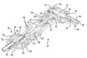
- FIG. 1is an exploded perspective view of a portion of a right angle attachment embodying the present invention, the drawing excluding the mounting coupling assembly that is used for securing the portion shown in the drawing of FIG. 1 to a rotary hand tool;
- FIG. 2is a perspective view of a driver nut that is used with the attachment of the present invention, the driver nut being screwed onto the output shaft of the rotary hand tool to which the attachment is attached;
- FIG. 3is an enlarged left end view of the driver nut shown in FIG. 2;
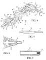
- FIG. 4is a sectional perspective view of the right angle attachment embodying the present invention.
- FIG. 5is a plan view of the flexible shaft that is used in the present invention.
- FIG. 6is a sectional view of a portion of a rotary hand tool to which the attachment of the present invention is attachable.
- FIG. 7is a sectional view of the transmission input shaft of the right angle attachment embodying the present invention.
- the present inventionis directed to an attachment, and preferably a right angle attachment that is configured to be attached to a small electrically powered rotary hand tool of the type that is used in woodworking, hobby work and the like, the attachment being small, lightweight, relatively vibration free and quiet in operation, and easily attached to a hand tool in a very short amount of time without the use of any special tools.
- the attachmenthas a flexible input shaft and an output shaft that are oriented at an angular orientation, such as approximately 90° relative to one another, with the flexible input shaft being coupled to the hand tool to compensate for misalignment between the input shaft and the output drive shaft of the tool.
- the attachmentis easily attached to the hand tool by merely removing the chuck that is a part of the original hand tool and screwing the chuck to the attachment output shaft, screwing a driver nut on the rotary tool output drive shaft, screwing a mounting coupling assembly onto a threaded end of the rotary tool case, fitting the attachment to the hand tool by merely sliding it into engagement and tightening the mounting coupling assembly by hand.
- the attachmenthas a fluted interior that cooperates wit a complementary fluted exterior on the adaptor so that the angular position of the attachment relative to the tool can be changed in small increments throughout a complete revolution. This enables a user to position the output shaft of the attachment to virtually any desired angular position relative to the hand tool. While the number of flutes can be varied, there are preferably 12 flutes in the preferred embodiment, which enables the angular position to be changed in 30° increments.
- the attachment indicated generally at 10includes a housing including components 12 and 14 in which a gear assembly, indicated generally at 16 , is placed.
- the gear assembly 16includes a pair of spiral bevel gears 18 and 20 which engage one another and translate the rotational movement at right angles, with the gear 20 being connected to an output shaft 22 .
- the output shaft 22is connected to a transmission output shaft 23 to which the gear 20 is actually attached, and which rides in spaced bearings 24 and 26 , preferably ball or roller bearings so that shaft gear can easily rotate, with the outer portion of the bearing being held in suitable recesses 27 in the housing components 12 and 14 .
- the gear assembly 16also has a hollow transmission input shaft 28 (also referred to as the hollow shaft) to which the gear 18 is attached, and also includes a flexible input shaft 30 (also referred to as the flexible shaft) that is located in the hollow shaft 28 is attached to it at its end 31 (see FIG. 7) beyond the end of the gear 18 .
- a pair of spaced bearings 32 and 34are provided which permit easy rotation of the gear 18 , shafts 28 and 30 .
- the gears 18 , 20 and the shafts 23 and 28are collectively referred to as the transmission.
- hollow transmission input shaft 28is secured or fixed within the housing 12 , 14 on the bearings 32 , 24 to accommodate high speed rotation, which is initiated by the flexible shaft 30 , which is not fixed relative to the housing, and is not supported by bearings.
- the shafts 23 and 28are oriented at generally a right angle to each other, it will be appreciated that the use of the flexible shaft 30 within a hollow shaft 28 may be used in other angular orientations and still provide the features of reduced misalignment. Also, the use of the present flexible shaft drive system may be employed in other types of attachments for power hand tools.
- FIG. 4which illustrates another perspective view of the attachment 10 , it shows a mounting coupling assembly, indicated generally at 36 , which is adapted to be screwed onto an electrically powered rotary hand tool 38 , a portion of which is shown in the cross-sectional view of FIG. 6 .
- the hand tool 38is preferably of the type which has a cord that is plugged into a source of AC power, but the present invention can be used with any rotary hand tool that may be powered with a battery pack or other source of electrical power.
- the hand tool 38has a threaded end portion 40 of its case or tool case 41 which may normally have a threaded end cap attached to it which has been removed and the hand tool 38 also has a threaded output drive shaft 42 on which a chuck 44 is typically provided. It should be understood that the chuck 44 may be secured to the output drive shaft 42 in other known ways besides threaded engagement.
- the chuck 44has been removed from the shaft 42 and applied to the output shaft 22 of the attachment 10 as shown in FIG. 4 .
- the chuck 44has a collet 46 and collet nut 48 of conventional design. It should be apparent that it is preferred that the output shaft 42 be of the same diameter as the output shaft 22 of the attachment 10 so that the same chuck 44 can be removed from the rotary hand tool and applied to the attachment by simply unscrewing from one and screwing it onto the other.
- the mounting coupling assembly 36includes an adaptor 50 that has internal threads 52 that are configured to engage threads 40 of the hand tool 38 .
- an adaptor 50may be dimensioned to engage the housing 12 , 14 , depending on the application.
- the adaptor 50is screwed onto the hand tool 38 until it is tight and secure.
- the adaptor 50as an internal opening 54 that is larger than the diameter of the output drive shaft 42 of the hand tool, with the spacing between the outside diameter of the shaft 42 and the inside diameter 54 of the adaptor 50 being sufficient to enable a driver nut 56 to be screwed or otherwise attached onto the shaft 42 without interference with the adaptor 50 itself.
- the adaptor 50also has a outwardly extending annular flange 58 which is adapted to engage an interiorly or radially inwardly directed collar portion 62 of a mounting sleeve 60 , preferably taking the form of a finger nut, when the sleeve 60 is tightened during attachment to the tool 38 .
- the mounting sleeve 60has interior threads 64 for engaging a threaded portion 66 formed by the housing components 12 and 14 of the attachment. It should be understood that the mounting coupling assembly 36 can be reversed so that the adaptor 50 is secured to the housing 12 , 14 , and the mounting sleeve 60 may be engageable on the tool case 41 , depending on the application.
- the inside surface of the housing components 12 and 14contains a plurality of axially directed splines 68 that extend around the complete circumference.
- the adaptor 50has a cylindrical end portion 70 which has an outside surface that contains the same number of complementary splines 71 , and these splines are adapted to engage the splines 68 of the attachment 10 . While there may be a greater or lesser number of splines, the preferred embodiment has 12 splines 68 and 71 which permit the attachment 10 to be positioned in 12 different angular positions in 30° intervals relative to the rotary tool.
- This featurepermits the user to position the angle of the attachment 10 relative to the rotary tool 38 for optimum personal preference for the task being performed.
- Another advantage of this splined engagement featureis that the user always knows before attachment the angular orientation of the output shaft 22 relative to the axis of the rotary tool 38 . This means that the attachment will not rotate axially relative to the tool axis during assembly, which could potentially interfere with the ergonomics of the attachment relative to the controls of the tool 38 .
- the complementary splined configuration of the adaptor 50 and housing components 12 and 14have been shown and described, other complementary structural configurations can be used to mount the attachment 10 at various angular positions relative to the rotary tool 38 .
- the flexible input shaft 30 shown in FIGS. 1, 4 and 5is generally circular, except that the ends 72 and 74 are square.
- the flexible shaft 30is of conventional design and includes a core of wire plus four opposed layers of concentrically wrapped wire.
- the coreis preferably approximately 1 ⁇ 8 inch in diameter.
- the end portionsare preferably squared by a cold swaging process and the flexible shaft is approximately an inch long and is preferably model No. 130-21 manufactured by the Suhner Company of Rome, Ga.
- the flexible input shaft 30has a diameter which is less than a bore 29 defined by the hollow transmission input shaft 28 , and thus can flex to a certain degree within the bore. Since the flexible input shaft 30 fits within the hollow input shaft 28 and extends beyond the end thereof, the fact that the flexible shaft can flex with in the hollow shaft allows for the use of a longer flexible shaft to better accommodate misalignment between the output drive shaft 42 and the hollow shaft 28 while allowing for a shorter profile of the attachment 10 .
- the flexible shaft 30Since the flexible shaft 30 has an outer diameter slightly less than the inside diameter of the input shaft 28 , it is free to flex during operation and is therefore able to compensate for any structural misalignment between the attachment and the rotary tool 38 .
- the ability of the shaft 30 to flexreduces the need for exceedingly close manufacturing tolerances and is important in reducing vibration and noise during operation.
- the flexible shaft 30is insertable into the driver nut 56 (FIG. 4) when the attachment is applied to the rotary tool 38 .
- the flexible shaft 30is attached to the hollow transmission input shaft 28 at the end thereof by a swaging or crimping of the end 31 of the shaft 28 , which is just beyond the gear 18 .
- One or both of the end portions of the flexible shaft 30may have a beveled portion as shown in the right end 74 in FIG. 5 to remove the sharp 90 degree corners to further facilitate insertion of the flexible shaft into the driver nut during installation of the attachment 10 or into end 31 of the input shaft during the manufacturing process.
- the bevelmay have an approximately 45 degree angle as shown or it may be a greater or lesser angle or even curved.
- the surfacecan be formed by swaging, grinding or cutting as desired.
- the driver nut 56 shown in FIGS. 2 and 3has a hexagonal outer configuration so that a wrench can be used to apply it to or remove it from the output shaft 42 .
- the driver nuthas a hollow interior 76 that is provided with a threaded surface and is sized so that the driver nut 56 can be screwed onto the output shaft 42 .
- the right end portion 78has an opening 80 that is smaller than the threaded interior 76 and thereby forms an interior annular shelf 82 at the right end portion 78 that engages the outer end of the output shaft 42 when the nut 56 is tightened on the output shaft.
- the opening 80also has an interior grooved configuration that preferably contains 8 symmetrically located grooves 84 This 8 point groove configuration is used to provide easier insertion of the square end 74 of the flexible shaft 30 into the driver nut 56 when the attachment is mounted to the rotary hand tool 38 . It should be understood that a 4 point grooved configuration could be used, but with a configuration, the square ended shaft would have to be more accurately aligned to enable insertion of the flexible shaft 30 .
- the preferred embodimentemploys a square ended flexible shaft configuration and an 8 groove opening in the driver nut 56 , the flexible shaft could have a multi-sided configuration that is other than square, i.e., it could be triangular or even pentagonal.
- the spirit of the inventionwould encompass a number of grooves that is larger than the number of sides of the multi-sided end of the flexible shaft.
- the attachmentis small and compact, and is capable of being easily attached to a rotary hand tool without the need for special tools. Moreover, it is quiet during operation and does not exhibit undesirable vibration that is often experienced from other prior art designs.
- the attachmentalso has the advantage that it can be attached to a rotary hand tool at any one of a plurality of angular positions so that a user can utilize the optimum angular position for any given task if desired.
- driver nut, finger nut assembly, adjustable angular adjustability and flexible shaft designare shown and described with respect to the right angle attachment, the invention is not limited to a right angle attachment and can be used with other conceivable hand tool applications where the design considerations in coupling axially aligned rotatable shafts are similar, such as surgical and other instruments, for example.
Landscapes
- Engineering & Computer Science (AREA)
- Mechanical Engineering (AREA)
- Flexible Shafts (AREA)
- Harvester Elements (AREA)
Abstract
Description
Claims (16)
Priority Applications (3)
| Application Number | Priority Date | Filing Date | Title |
|---|---|---|---|
| US09/515,195US6463824B1 (en) | 2000-02-29 | 2000-02-29 | Right angle attachment for power hand tool |
| EP01102788AEP1129825B1 (en) | 2000-02-29 | 2001-02-09 | Right angle attachment for power hand tool |
| DE60114903TDE60114903T2 (en) | 2000-02-29 | 2001-02-09 | Right-angle accessory for hand tool |
Applications Claiming Priority (1)
| Application Number | Priority Date | Filing Date | Title |
|---|---|---|---|
| US09/515,195US6463824B1 (en) | 2000-02-29 | 2000-02-29 | Right angle attachment for power hand tool |
Publications (1)
| Publication Number | Publication Date |
|---|---|
| US6463824B1true US6463824B1 (en) | 2002-10-15 |
Family
ID=24050333
Family Applications (1)
| Application Number | Title | Priority Date | Filing Date |
|---|---|---|---|
| US09/515,195Expired - LifetimeUS6463824B1 (en) | 2000-02-29 | 2000-02-29 | Right angle attachment for power hand tool |
Country Status (3)
| Country | Link |
|---|---|
| US (1) | US6463824B1 (en) |
| EP (1) | EP1129825B1 (en) |
| DE (1) | DE60114903T2 (en) |
Cited By (187)
| Publication number | Priority date | Publication date | Assignee | Title |
|---|---|---|---|---|
| US20020183762A1 (en)* | 2001-06-01 | 2002-12-05 | Ams Research Corporation | Bone anchor inserters and methods |
| US6523442B2 (en)* | 2000-12-07 | 2003-02-25 | Acradyne Inc. | Torque tool assembly |
| US20040045417A1 (en)* | 2002-09-10 | 2004-03-11 | Chiu Li Jiun | Handgrip structure for fixing angled socket |
| US20040188119A1 (en)* | 2003-03-24 | 2004-09-30 | Hsin-Chu Chen | Portable electric-powered tool |
| US20070102178A1 (en)* | 2005-11-09 | 2007-05-10 | Nomis Llc | Angle drive attachment |
| US20080003070A1 (en)* | 2006-06-30 | 2008-01-03 | Bung-Jzyy Hor | Tool adapter |
| US20080098553A1 (en)* | 2006-08-15 | 2008-05-01 | Dayton Douglas C | Systems and methods for robotic gutter cleaning |
| US20080104780A1 (en)* | 2006-08-15 | 2008-05-08 | Dayton Douglas C | Systems and methods of a gutter cleaning system |
| US20080216869A1 (en)* | 2006-08-15 | 2008-09-11 | Dayton Douglas C | Systems and methods for robotic gutter cleaning along an axis of rotation |
| US20080250570A1 (en)* | 2006-08-15 | 2008-10-16 | Dayton Douglas C | Systems and methods of a power tool system with interchangeable functional attachments powered by a direct rotational drive |
| US20100263494A1 (en)* | 2009-04-15 | 2010-10-21 | Custom Spec Engineering, Inc. | Indexable offset adaptor |
| US7913345B2 (en) | 2006-08-15 | 2011-03-29 | Umagination Labs, L.P. | Systems and methods of a power tool system with interchangeable functional attachments |
| US20110072946A1 (en)* | 2009-09-29 | 2011-03-31 | Credo Technology Corporation | Accessory attachment system for an oscillating power tool |
| USD636245S1 (en)* | 2010-03-19 | 2011-04-19 | Nomis Llc | Right angle drive |
| US20110186316A1 (en)* | 2010-02-04 | 2011-08-04 | Credo Technology Corporation | drive system for interconnecting attachment devices and handheld rotary power tools |
| US20120011954A1 (en)* | 2010-07-13 | 2012-01-19 | Nomis Llc | Right Angle Drive Having Dual Shaft Bearings |
| US20120024096A1 (en)* | 2010-07-29 | 2012-02-02 | Nomis Llc | Right angle drive with center support |
| US20120255749A1 (en)* | 2011-04-05 | 2012-10-11 | Ingersoll-Rand Company | Rotary impact device |
| USD670148S1 (en)* | 2011-04-14 | 2012-11-06 | Ching-Yi Wang | Multiple-angle transmission tool |
| USD692742S1 (en) | 2012-11-20 | 2013-11-05 | Black & Decker Inc. | Right angle attachment |
| USD712225S1 (en) | 2013-12-27 | 2014-09-02 | Nomis Llc | Angle driver |
| US20150034346A1 (en)* | 2012-03-30 | 2015-02-05 | Hitachi Koki Cp., Ltd. | Impact Tool |
| US20160008969A1 (en)* | 2011-03-11 | 2016-01-14 | Stanley D. Winnard | Handheld drive device |
| US9314852B2 (en) | 2011-12-15 | 2016-04-19 | Black & Decker Inc. | Right angle attachment for power tools |
| USD764248S1 (en)* | 2015-04-22 | 2016-08-23 | Nomis Llc | Right angle drive |
| US9463557B2 (en) | 2014-01-31 | 2016-10-11 | Ingersoll-Rand Company | Power socket for an impact tool |
| US9469017B2 (en) | 2014-01-31 | 2016-10-18 | Ingersoll-Rand Company | One-piece power socket for an impact tool |
| US20170095897A1 (en)* | 2014-03-20 | 2017-04-06 | Amvalor | Machine tool, in particular for drilling |
| USD789171S1 (en) | 2016-01-21 | 2017-06-13 | Nomis Llc | Right angle drive |
| US9751176B2 (en) | 2014-05-30 | 2017-09-05 | Black & Decker Inc. | Power tool accessory attachment system |
| US9826989B2 (en)* | 2013-09-27 | 2017-11-28 | Eui Tak CHU | Drilling device for acromioplasty |
| US20190126418A1 (en)* | 2017-10-02 | 2019-05-02 | Bachus and Son, Inc. | Battery Powered Right Angle Aircraft Drill |
| US10399214B2 (en) | 2014-12-17 | 2019-09-03 | Stanley D. Winnard | Ratchet wrench |
| US20200060713A1 (en)* | 2014-03-26 | 2020-02-27 | Ethicon Llc | Feedback algorithms for manual bailout systems for surgical instruments |
| US10697250B2 (en)* | 2015-04-02 | 2020-06-30 | Sandvik Intellectual Property Ab | Multi-functional connector, drill head, and method |
| USD907456S1 (en) | 2019-05-21 | 2021-01-12 | Nomis Llc | Right angle drill attachment |
| USD907455S1 (en) | 2019-05-21 | 2021-01-12 | Nomis Llc | Right angle drive attachment |
| US10946507B1 (en)* | 2019-10-04 | 2021-03-16 | Master Air Tool Co., Ltd. | Power tool |
| US11453108B2 (en)* | 2019-12-09 | 2022-09-27 | Robert Bosch Tool Corporation | Hand held rotary tool with adapter for quick connection to accessories |
| US11534897B2 (en) | 2019-05-09 | 2022-12-27 | Black & Decker Inc. | Modular tool bit holder system |
| US11696759B2 (en) | 2017-06-28 | 2023-07-11 | Cilag Gmbh International | Surgical stapling instruments comprising shortened staple cartridge noses |
| US11701111B2 (en) | 2019-12-19 | 2023-07-18 | Cilag Gmbh International | Method for operating a surgical stapling instrument |
| US11707273B2 (en) | 2012-06-15 | 2023-07-25 | Cilag Gmbh International | Articulatable surgical instrument comprising a firing drive |
| US11712244B2 (en) | 2015-09-30 | 2023-08-01 | Cilag Gmbh International | Implantable layer with spacer fibers |
| US11717291B2 (en) | 2021-03-22 | 2023-08-08 | Cilag Gmbh International | Staple cartridge comprising staples configured to apply different tissue compression |
| US11717297B2 (en) | 2014-09-05 | 2023-08-08 | Cilag Gmbh International | Smart cartridge wake up operation and data retention |
| US11717294B2 (en) | 2014-04-16 | 2023-08-08 | Cilag Gmbh International | End effector arrangements comprising indicators |
| US11723657B2 (en) | 2021-02-26 | 2023-08-15 | Cilag Gmbh International | Adjustable communication based on available bandwidth and power capacity |
| US11723658B2 (en) | 2021-03-22 | 2023-08-15 | Cilag Gmbh International | Staple cartridge comprising a firing lockout |
| US11723662B2 (en) | 2021-05-28 | 2023-08-15 | Cilag Gmbh International | Stapling instrument comprising an articulation control display |
| US11730474B2 (en) | 2005-08-31 | 2023-08-22 | Cilag Gmbh International | Fastener cartridge assembly comprising a movable cartridge and a staple driver arrangement |
| US11730473B2 (en) | 2021-02-26 | 2023-08-22 | Cilag Gmbh International | Monitoring of manufacturing life-cycle |
| US11730477B2 (en) | 2008-10-10 | 2023-08-22 | Cilag Gmbh International | Powered surgical system with manually retractable firing system |
| US11730471B2 (en) | 2016-02-09 | 2023-08-22 | Cilag Gmbh International | Articulatable surgical instruments with single articulation link arrangements |
| US11737751B2 (en) | 2020-12-02 | 2023-08-29 | Cilag Gmbh International | Devices and methods of managing energy dissipated within sterile barriers of surgical instrument housings |
| US11737749B2 (en) | 2021-03-22 | 2023-08-29 | Cilag Gmbh International | Surgical stapling instrument comprising a retraction system |
| US11737754B2 (en) | 2010-09-30 | 2023-08-29 | Cilag Gmbh International | Surgical stapler with floating anvil |
| US11744593B2 (en) | 2019-06-28 | 2023-09-05 | Cilag Gmbh International | Method for authenticating the compatibility of a staple cartridge with a surgical instrument |
| US11744583B2 (en) | 2021-02-26 | 2023-09-05 | Cilag Gmbh International | Distal communication array to tune frequency of RF systems |
| US11744588B2 (en) | 2015-02-27 | 2023-09-05 | Cilag Gmbh International | Surgical stapling instrument including a removably attachable battery pack |
| US11744603B2 (en) | 2021-03-24 | 2023-09-05 | Cilag Gmbh International | Multi-axis pivot joints for surgical instruments and methods for manufacturing same |
| US11749877B2 (en) | 2021-02-26 | 2023-09-05 | Cilag Gmbh International | Stapling instrument comprising a signal antenna |
| US11744581B2 (en) | 2020-12-02 | 2023-09-05 | Cilag Gmbh International | Powered surgical instruments with multi-phase tissue treatment |
| US11751867B2 (en) | 2017-12-21 | 2023-09-12 | Cilag Gmbh International | Surgical instrument comprising sequenced systems |
| US11751869B2 (en) | 2021-02-26 | 2023-09-12 | Cilag Gmbh International | Monitoring of multiple sensors over time to detect moving characteristics of tissue |
| US11759202B2 (en) | 2021-03-22 | 2023-09-19 | Cilag Gmbh International | Staple cartridge comprising an implantable layer |
| US11759208B2 (en) | 2015-12-30 | 2023-09-19 | Cilag Gmbh International | Mechanisms for compensating for battery pack failure in powered surgical instruments |
| US20230302620A1 (en)* | 2022-03-28 | 2023-09-28 | Milwaukee Electric Tool Corporation | Rotary power tool |
| US11771419B2 (en) | 2019-06-28 | 2023-10-03 | Cilag Gmbh International | Packaging for a replaceable component of a surgical stapling system |
| US11779420B2 (en) | 2012-06-28 | 2023-10-10 | Cilag Gmbh International | Robotic surgical attachments having manually-actuated retraction assemblies |
| US11779330B2 (en) | 2020-10-29 | 2023-10-10 | Cilag Gmbh International | Surgical instrument comprising a jaw alignment system |
| US11779336B2 (en) | 2016-02-12 | 2023-10-10 | Cilag Gmbh International | Mechanisms for compensating for drivetrain failure in powered surgical instruments |
| US11793513B2 (en) | 2017-06-20 | 2023-10-24 | Cilag Gmbh International | Systems and methods for controlling motor speed according to user input for a surgical instrument |
| US11793512B2 (en) | 2005-08-31 | 2023-10-24 | Cilag Gmbh International | Staple cartridges for forming staples having differing formed staple heights |
| US11793509B2 (en) | 2012-03-28 | 2023-10-24 | Cilag Gmbh International | Staple cartridge including an implantable layer |
| US11793518B2 (en) | 2006-01-31 | 2023-10-24 | Cilag Gmbh International | Powered surgical instruments with firing system lockout arrangements |
| US11801047B2 (en) | 2008-02-14 | 2023-10-31 | Cilag Gmbh International | Surgical stapling system comprising a control circuit configured to selectively monitor tissue impedance and adjust control of a motor |
| US11811253B2 (en) | 2016-04-18 | 2023-11-07 | Cilag Gmbh International | Surgical robotic system with fault state detection configurations based on motor current draw |
| US11806011B2 (en) | 2021-03-22 | 2023-11-07 | Cilag Gmbh International | Stapling instrument comprising tissue compression systems |
| US11806013B2 (en) | 2012-06-28 | 2023-11-07 | Cilag Gmbh International | Firing system arrangements for surgical instruments |
| US11812961B2 (en) | 2007-01-10 | 2023-11-14 | Cilag Gmbh International | Surgical instrument including a motor control system |
| US11812954B2 (en) | 2008-09-23 | 2023-11-14 | Cilag Gmbh International | Robotically-controlled motorized surgical instrument with an end effector |
| US11812964B2 (en) | 2021-02-26 | 2023-11-14 | Cilag Gmbh International | Staple cartridge comprising a power management circuit |
| US11812965B2 (en) | 2010-09-30 | 2023-11-14 | Cilag Gmbh International | Layer of material for a surgical end effector |
| US11826012B2 (en) | 2021-03-22 | 2023-11-28 | Cilag Gmbh International | Stapling instrument comprising a pulsed motor-driven firing rack |
| US11826042B2 (en) | 2021-03-22 | 2023-11-28 | Cilag Gmbh International | Surgical instrument comprising a firing drive including a selectable leverage mechanism |
| US11839375B2 (en) | 2005-08-31 | 2023-12-12 | Cilag Gmbh International | Fastener cartridge assembly comprising an anvil and different staple heights |
| US11839352B2 (en) | 2007-01-11 | 2023-12-12 | Cilag Gmbh International | Surgical stapling device with an end effector |
| US11849941B2 (en) | 2007-06-29 | 2023-12-26 | Cilag Gmbh International | Staple cartridge having staple cavities extending at a transverse angle relative to a longitudinal cartridge axis |
| US11849943B2 (en) | 2020-12-02 | 2023-12-26 | Cilag Gmbh International | Surgical instrument with cartridge release mechanisms |
| US11849946B2 (en) | 2015-09-23 | 2023-12-26 | Cilag Gmbh International | Surgical stapler having downstream current-based motor control |
| US11849945B2 (en) | 2021-03-24 | 2023-12-26 | Cilag Gmbh International | Rotary-driven surgical stapling assembly comprising eccentrically driven firing member |
| US11849952B2 (en) | 2010-09-30 | 2023-12-26 | Cilag Gmbh International | Staple cartridge comprising staples positioned within a compressible portion thereof |
| US11850310B2 (en) | 2010-09-30 | 2023-12-26 | Cilag Gmbh International | Staple cartridge including an adjunct |
| US11857187B2 (en) | 2010-09-30 | 2024-01-02 | Cilag Gmbh International | Tissue thickness compensator comprising controlled release and expansion |
| US11857181B2 (en) | 2007-06-04 | 2024-01-02 | Cilag Gmbh International | Robotically-controlled shaft based rotary drive systems for surgical instruments |
| US11871939B2 (en) | 2017-06-20 | 2024-01-16 | Cilag Gmbh International | Method for closed loop control of motor velocity of a surgical stapling and cutting instrument |
| US11871923B2 (en) | 2008-09-23 | 2024-01-16 | Cilag Gmbh International | Motorized surgical instrument |
| US11877748B2 (en) | 2006-10-03 | 2024-01-23 | Cilag Gmbh International | Robotically-driven surgical instrument with E-beam driver |
| US11883020B2 (en) | 2006-01-31 | 2024-01-30 | Cilag Gmbh International | Surgical instrument having a feedback system |
| US11882987B2 (en) | 2004-07-28 | 2024-01-30 | Cilag Gmbh International | Articulating surgical stapling instrument incorporating a two-piece E-beam firing mechanism |
| US11883026B2 (en) | 2014-04-16 | 2024-01-30 | Cilag Gmbh International | Fastener cartridge assemblies and staple retainer cover arrangements |
| USD1013170S1 (en) | 2020-10-29 | 2024-01-30 | Cilag Gmbh International | Surgical instrument assembly |
| US11883025B2 (en) | 2010-09-30 | 2024-01-30 | Cilag Gmbh International | Tissue thickness compensator comprising a plurality of layers |
| US11890012B2 (en) | 2004-07-28 | 2024-02-06 | Cilag Gmbh International | Staple cartridge comprising cartridge body and attached support |
| US11890005B2 (en) | 2017-06-29 | 2024-02-06 | Cilag Gmbh International | Methods for closed loop velocity control for robotic surgical instrument |
| US11890029B2 (en) | 2006-01-31 | 2024-02-06 | Cilag Gmbh International | Motor-driven surgical cutting and fastening instrument |
| US11890008B2 (en) | 2006-01-31 | 2024-02-06 | Cilag Gmbh International | Surgical instrument with firing lockout |
| US11890015B2 (en) | 2015-09-30 | 2024-02-06 | Cilag Gmbh International | Compressible adjunct with crossing spacer fibers |
| US11896222B2 (en) | 2017-12-15 | 2024-02-13 | Cilag Gmbh International | Methods of operating surgical end effectors |
| US11896218B2 (en) | 2021-03-24 | 2024-02-13 | Cilag Gmbh International | Method of using a powered stapling device |
| US11896217B2 (en) | 2020-10-29 | 2024-02-13 | Cilag Gmbh International | Surgical instrument comprising an articulation lock |
| US11896219B2 (en) | 2021-03-24 | 2024-02-13 | Cilag Gmbh International | Mating features between drivers and underside of a cartridge deck |
| US11903581B2 (en) | 2019-04-30 | 2024-02-20 | Cilag Gmbh International | Methods for stapling tissue using a surgical instrument |
| US11911027B2 (en) | 2010-09-30 | 2024-02-27 | Cilag Gmbh International | Adhesive film laminate |
| US11918220B2 (en) | 2012-03-28 | 2024-03-05 | Cilag Gmbh International | Tissue thickness compensator comprising tissue ingrowth features |
| US11918215B2 (en) | 2016-12-21 | 2024-03-05 | Cilag Gmbh International | Staple cartridge with array of staple pockets |
| US11918222B2 (en) | 2014-04-16 | 2024-03-05 | Cilag Gmbh International | Stapling assembly having firing member viewing windows |
| US11918210B2 (en) | 2014-10-16 | 2024-03-05 | Cilag Gmbh International | Staple cartridge comprising a cartridge body including a plurality of wells |
| US11918208B2 (en) | 2011-05-27 | 2024-03-05 | Cilag Gmbh International | Robotically-controlled shaft based rotary drive systems for surgical instruments |
| US11918212B2 (en) | 2015-03-31 | 2024-03-05 | Cilag Gmbh International | Surgical instrument with selectively disengageable drive systems |
| US11931034B2 (en) | 2016-12-21 | 2024-03-19 | Cilag Gmbh International | Surgical stapling instruments with smart staple cartridges |
| US11931028B2 (en) | 2016-04-15 | 2024-03-19 | Cilag Gmbh International | Surgical instrument with multiple program responses during a firing motion |
| US11931025B2 (en) | 2020-10-29 | 2024-03-19 | Cilag Gmbh International | Surgical instrument comprising a releasable closure drive lock |
| USD1018577S1 (en) | 2017-06-28 | 2024-03-19 | Cilag Gmbh International | Display screen or portion thereof with a graphical user interface for a surgical instrument |
| US11937816B2 (en) | 2021-10-28 | 2024-03-26 | Cilag Gmbh International | Electrical lead arrangements for surgical instruments |
| US11944338B2 (en) | 2015-03-06 | 2024-04-02 | Cilag Gmbh International | Multiple level thresholds to modify operation of powered surgical instruments |
| US11944296B2 (en) | 2020-12-02 | 2024-04-02 | Cilag Gmbh International | Powered surgical instruments with external connectors |
| US11950777B2 (en) | 2021-02-26 | 2024-04-09 | Cilag Gmbh International | Staple cartridge comprising an information access control system |
| US11957345B2 (en) | 2013-03-01 | 2024-04-16 | Cilag Gmbh International | Articulatable surgical instruments with conductive pathways for signal communication |
| US11957339B2 (en) | 2018-08-20 | 2024-04-16 | Cilag Gmbh International | Method for fabricating surgical stapler anvils |
| US11963680B2 (en) | 2017-10-31 | 2024-04-23 | Cilag Gmbh International | Cartridge body design with force reduction based on firing completion |
| USD1023710S1 (en) | 2021-03-19 | 2024-04-23 | Black & Decker Inc. | Power tool |
| US11974746B2 (en) | 2014-04-16 | 2024-05-07 | Cilag Gmbh International | Anvil for use with a surgical stapling assembly |
| US11974742B2 (en) | 2017-08-03 | 2024-05-07 | Cilag Gmbh International | Surgical system comprising an articulation bailout |
| US11974747B2 (en) | 2011-05-27 | 2024-05-07 | Cilag Gmbh International | Surgical stapling instruments with rotatable staple deployment arrangements |
| US11980362B2 (en) | 2021-02-26 | 2024-05-14 | Cilag Gmbh International | Surgical instrument system comprising a power transfer coil |
| US11980366B2 (en) | 2006-10-03 | 2024-05-14 | Cilag Gmbh International | Surgical instrument |
| US11980363B2 (en) | 2021-10-18 | 2024-05-14 | Cilag Gmbh International | Row-to-row staple array variations |
| US11986183B2 (en) | 2008-02-14 | 2024-05-21 | Cilag Gmbh International | Surgical cutting and fastening instrument comprising a plurality of sensors to measure an electrical parameter |
| US11992214B2 (en) | 2013-03-14 | 2024-05-28 | Cilag Gmbh International | Control systems for surgical instruments |
| US11992213B2 (en) | 2016-12-21 | 2024-05-28 | Cilag Gmbh International | Surgical stapling instruments with replaceable staple cartridges |
| US11992921B2 (en) | 2011-04-05 | 2024-05-28 | Ingersoll-Rand Industrial U.S., Inc. | Impact wrench having dynamically tuned drive components and method thereof |
| US11998198B2 (en) | 2004-07-28 | 2024-06-04 | Cilag Gmbh International | Surgical stapling instrument incorporating a two-piece E-beam firing mechanism |
| US11998206B2 (en) | 2008-02-14 | 2024-06-04 | Cilag Gmbh International | Detachable motor powered surgical instrument |
| US11998194B2 (en) | 2008-02-15 | 2024-06-04 | Cilag Gmbh International | Surgical stapling assembly comprising an adjunct applicator |
| US12011166B2 (en) | 2016-12-21 | 2024-06-18 | Cilag Gmbh International | Articulatable surgical stapling instruments |
| US12016564B2 (en) | 2014-09-26 | 2024-06-25 | Cilag Gmbh International | Circular fastener cartridges for applying radially expandable fastener lines |
| US12023022B2 (en) | 2014-03-26 | 2024-07-02 | Cilag Gmbh International | Systems and methods for controlling a segmented circuit |
| US12029415B2 (en) | 2008-09-23 | 2024-07-09 | Cilag Gmbh International | Motor-driven surgical cutting instrument |
| US12035913B2 (en) | 2019-12-19 | 2024-07-16 | Cilag Gmbh International | Staple cartridge comprising a deployable knife |
| US12053175B2 (en) | 2020-10-29 | 2024-08-06 | Cilag Gmbh International | Surgical instrument comprising a stowed closure actuator stop |
| US12053176B2 (en) | 2013-08-23 | 2024-08-06 | Cilag Gmbh International | End effector detention systems for surgical instruments |
| US12076096B2 (en) | 2017-12-19 | 2024-09-03 | Cilag Gmbh International | Method for determining the position of a rotatable jaw of a surgical instrument attachment assembly |
| US12076017B2 (en) | 2014-09-18 | 2024-09-03 | Cilag Gmbh International | Surgical instrument including a deployable knife |
| US12076008B2 (en) | 2018-08-20 | 2024-09-03 | Cilag Gmbh International | Method for operating a powered articulatable surgical instrument |
| US12076011B2 (en) | 2017-10-30 | 2024-09-03 | Cilag Gmbh International | Surgical stapler knife motion controls |
| US12082806B2 (en) | 2007-01-10 | 2024-09-10 | Cilag Gmbh International | Surgical instrument with wireless communication between control unit and sensor transponders |
| US12089841B2 (en) | 2021-10-28 | 2024-09-17 | Cilag CmbH International | Staple cartridge identification systems |
| US12108951B2 (en) | 2021-02-26 | 2024-10-08 | Cilag Gmbh International | Staple cartridge comprising a sensing array and a temperature control system |
| US12108950B2 (en) | 2014-12-18 | 2024-10-08 | Cilag Gmbh International | Surgical instrument assembly comprising a flexible articulation system |
| US12114859B2 (en) | 2014-12-10 | 2024-10-15 | Cilag Gmbh International | Articulatable surgical instrument system |
| US12137912B2 (en) | 2015-09-30 | 2024-11-12 | Cilag Gmbh International | Compressible adjunct with attachment regions |
| US12144500B2 (en) | 2016-04-15 | 2024-11-19 | Cilag Gmbh International | Surgical instrument with multiple program responses during a firing motion |
| US12156653B2 (en) | 2015-12-30 | 2024-12-03 | Cilag Gmbh International | Surgical instruments with motor control circuits |
| US12161320B2 (en) | 2013-04-16 | 2024-12-10 | Cilag Gmbh International | Powered surgical stapler |
| US12171508B2 (en) | 2006-03-23 | 2024-12-24 | Cilag Gmbh International | Robotically-controlled surgical instrument with selectively articulatable end effector |
| US12171507B2 (en) | 2016-08-16 | 2024-12-24 | Cilag Gmbh International | Surgical tool with manual control of end effector jaws |
| US12213666B2 (en) | 2010-09-30 | 2025-02-04 | Cilag Gmbh International | Tissue thickness compensator comprising layers |
| US12213671B2 (en) | 2008-02-14 | 2025-02-04 | Cilag Gmbh International | Motorized system having a plurality of power sources |
| US12232723B2 (en) | 2014-03-26 | 2025-02-25 | Cilag Gmbh International | Systems and methods for controlling a segmented circuit |
| US12239316B2 (en) | 2011-05-27 | 2025-03-04 | Cilag Gmbh International | Automated end effector component reloading system for use with a robotic system |
| US12245764B2 (en) | 2016-12-21 | 2025-03-11 | Cilag Gmbh International | Shaft assembly comprising a lockout |
| US12245901B2 (en) | 2015-09-25 | 2025-03-11 | Cilag Gmbh International | Implantable layer comprising boundary indicators |
| USD1067007S1 (en) | 2021-03-19 | 2025-03-18 | Black & Decker Inc. | Attachment head for power tool |
| US12262888B2 (en) | 2018-08-20 | 2025-04-01 | Cilag Gmbh International | Surgical instruments with progressive jaw closure arrangements |
| US12324581B2 (en) | 2017-06-28 | 2025-06-10 | Cilag Gmbh International | Surgical instrument comprising selectively actuatable rotatable couplers |
| US12324580B2 (en) | 2021-02-26 | 2025-06-10 | Cilag Gmbh International | Method of powering and communicating with a staple cartridge |
| US12329381B2 (en) | 2019-04-30 | 2025-06-17 | Cilag Gmbh International | Stapling instrument comprising a mounted shaft orientation sensor |
| US12336705B2 (en) | 2017-12-21 | 2025-06-24 | Cilag Gmbh International | Continuous use self-propelled stapling instrument |
| US12383267B2 (en) | 2012-06-28 | 2025-08-12 | Cilag Gmbh International | Robotically powered surgical device with manually-actuatable reversing system |
| US12383259B2 (en) | 2014-09-26 | 2025-08-12 | Cilag Gmbh International | Method for creating a flexible staple line |
| US12414768B2 (en) | 2014-09-05 | 2025-09-16 | Cilag Gmbh International | Staple cartridge electrical contacts |
| US12432790B2 (en) | 2021-10-28 | 2025-09-30 | Cilag Gmbh International | Method and device for transmitting UART communications over a security short range wireless communication |
| US12433627B2 (en) | 2013-03-01 | 2025-10-07 | Cilag Gmbh International | Surgical instrument soft stop |
| US12433584B2 (en) | 2006-01-31 | 2025-10-07 | Cilag Gmbh International | Robotically-controlled end effector |
| US12440208B2 (en) | 2023-08-23 | 2025-10-14 | Cilag Gmbh International | Powered surgical instrument |
Families Citing this family (13)
| Publication number | Priority date | Publication date | Assignee | Title |
|---|---|---|---|---|
| US6048260A (en) | 1999-07-01 | 2000-04-11 | Roto-Zip Tool Corporation | Angle attachment for power tool |
| CA2459636C (en) | 2003-03-03 | 2010-02-16 | Credo Technology Corporation | Angle attachment for power tool |
| US7052382B2 (en)* | 2003-08-26 | 2006-05-30 | Credo Technology Corporation | Accessory attachment for rotary hand tools |
| DE102005026554B4 (en)* | 2005-06-06 | 2009-06-10 | Dirk Dammers | Method for introducing a locking groove in a groove flank |
| USD626395S1 (en) | 2009-12-18 | 2010-11-02 | Techtronic Power Tools Technology Limited | Tool head interface for connection to tool body |
| EP2388107B1 (en) | 2009-12-18 | 2019-09-04 | Techtronic Power Tools Technology Limited | Multi-function tool system |
| USD626398S1 (en) | 2009-12-18 | 2010-11-02 | Techtronic Power Tools Technology Limited | Handle interface |
| USD671892S1 (en) | 2011-04-15 | 2012-12-04 | Techtronic Power Tools Technology Limited | Portion of a power base |
| USD683605S1 (en) | 2011-04-15 | 2013-06-04 | Techtronic Power Tools Technology Limited | Portion of a tool head |
| USD683606S1 (en) | 2011-04-15 | 2013-06-04 | Techtronic Power Tools Technology Limited | Portion of a tool head |
| EP2809470B1 (en) | 2012-02-03 | 2020-01-15 | Milwaukee Electric Tool Corporation | Rotary hammer |
| CN102615536A (en)* | 2012-03-06 | 2012-08-01 | 马鞍山方圆回转支承股份有限公司 | 90-degree conversion chuck of numerical control drill |
| CN203665475U (en)* | 2013-12-19 | 2014-06-25 | 麦太保电动工具(中国)有限公司 | Connector used for connecting electric tool with adaptor |
Citations (10)
| Publication number | Priority date | Publication date | Assignee | Title |
|---|---|---|---|---|
| US3614419A (en)* | 1970-04-06 | 1971-10-19 | Xerox Corp | Multiple sheet detection system |
| US3724561A (en)* | 1971-09-09 | 1973-04-03 | F Merrels | Multiple tool driving unit |
| US4260381A (en)* | 1978-12-21 | 1981-04-07 | Kaltenbach & Voight Gmbh & Co. | Dental handpiece |
| US4286675A (en)* | 1979-06-25 | 1981-09-01 | Beaird-Poulan Division Of Emerson Electric Co. | Narrow profile power handle for line trimmer and the like |
| US4485682A (en)* | 1982-04-22 | 1984-12-04 | Robert Bosch Gmbh | Transducer for torque and/or angular displacement measurement, especially in power screwdrivers |
| US4748872A (en)* | 1986-04-28 | 1988-06-07 | Brown William J | Flexible power tools |
| US4913007A (en)* | 1989-02-02 | 1990-04-03 | Reynolds Randall W | Right angle extension tool |
| US5052496A (en)* | 1989-10-11 | 1991-10-01 | Ingersoll-Rand Company | Apparatus for attaching power tool housing extensions |
| US5749728A (en)* | 1990-11-15 | 1998-05-12 | Young Dental Manufacturing Company | Method of assembling a dental prophylaxis angle |
| US5863159A (en)* | 1997-12-12 | 1999-01-26 | Lasko; Leonard J. | Drill angle attachment coupling |
Family Cites Families (2)
| Publication number | Priority date | Publication date | Assignee | Title |
|---|---|---|---|---|
| US5020281A (en)* | 1989-04-03 | 1991-06-04 | American Pneumatic Technologies, Inc. | High speed rotary hand tool with adjustable head coupling |
| DE4207138C1 (en)* | 1992-03-06 | 1993-07-22 | Unislip Gmbh, 5190 Stolberg, De | Tool adaptor for portable power drill - has tapped bush with non-round external surface for coupling sleeve engaging polygonal portion on drill shaft |
- 2000
- 2000-02-29USUS09/515,195patent/US6463824B1/ennot_activeExpired - Lifetime
- 2001
- 2001-02-09DEDE60114903Tpatent/DE60114903T2/ennot_activeExpired - Lifetime
- 2001-02-09EPEP01102788Apatent/EP1129825B1/ennot_activeExpired - Lifetime
Patent Citations (10)
| Publication number | Priority date | Publication date | Assignee | Title |
|---|---|---|---|---|
| US3614419A (en)* | 1970-04-06 | 1971-10-19 | Xerox Corp | Multiple sheet detection system |
| US3724561A (en)* | 1971-09-09 | 1973-04-03 | F Merrels | Multiple tool driving unit |
| US4260381A (en)* | 1978-12-21 | 1981-04-07 | Kaltenbach & Voight Gmbh & Co. | Dental handpiece |
| US4286675A (en)* | 1979-06-25 | 1981-09-01 | Beaird-Poulan Division Of Emerson Electric Co. | Narrow profile power handle for line trimmer and the like |
| US4485682A (en)* | 1982-04-22 | 1984-12-04 | Robert Bosch Gmbh | Transducer for torque and/or angular displacement measurement, especially in power screwdrivers |
| US4748872A (en)* | 1986-04-28 | 1988-06-07 | Brown William J | Flexible power tools |
| US4913007A (en)* | 1989-02-02 | 1990-04-03 | Reynolds Randall W | Right angle extension tool |
| US5052496A (en)* | 1989-10-11 | 1991-10-01 | Ingersoll-Rand Company | Apparatus for attaching power tool housing extensions |
| US5749728A (en)* | 1990-11-15 | 1998-05-12 | Young Dental Manufacturing Company | Method of assembling a dental prophylaxis angle |
| US5863159A (en)* | 1997-12-12 | 1999-01-26 | Lasko; Leonard J. | Drill angle attachment coupling |
Non-Patent Citations (3)
| Title |
|---|
| Proxxon(R)-Long Neck Angle Milling/Drilling Unit WB 220/E Roger Konig & Jurgen Kraft GbR-Web page printout Jun. 3, 1999, www.sell-it-easy.de/proxxon/english/wb220.htm. |
| Proxxon®—Long Neck Angle Milling/Drilling Unit WB 220/E Roger Konig & Jurgen Kraft GbR—Web page printout Jun. 3, 1999, www.sell-it-easy.de/proxxon/english/wb220.htm. |
| Robart Modeling Tools, ROB421 "Robart Right Angle Drive" Web page printout Jun. 3, 1999, www.robart.com/pages/MODTOOLS.htm. |
Cited By (267)
| Publication number | Priority date | Publication date | Assignee | Title |
|---|---|---|---|---|
| US6523442B2 (en)* | 2000-12-07 | 2003-02-25 | Acradyne Inc. | Torque tool assembly |
| US20020183762A1 (en)* | 2001-06-01 | 2002-12-05 | Ams Research Corporation | Bone anchor inserters and methods |
| US20040045417A1 (en)* | 2002-09-10 | 2004-03-11 | Chiu Li Jiun | Handgrip structure for fixing angled socket |
| US20040188119A1 (en)* | 2003-03-24 | 2004-09-30 | Hsin-Chu Chen | Portable electric-powered tool |
| US11896225B2 (en) | 2004-07-28 | 2024-02-13 | Cilag Gmbh International | Staple cartridge comprising a pan |
| US11882987B2 (en) | 2004-07-28 | 2024-01-30 | Cilag Gmbh International | Articulating surgical stapling instrument incorporating a two-piece E-beam firing mechanism |
| US11890012B2 (en) | 2004-07-28 | 2024-02-06 | Cilag Gmbh International | Staple cartridge comprising cartridge body and attached support |
| US12029423B2 (en) | 2004-07-28 | 2024-07-09 | Cilag Gmbh International | Surgical stapling instrument comprising a staple cartridge |
| US11963679B2 (en) | 2004-07-28 | 2024-04-23 | Cilag Gmbh International | Articulating surgical stapling instrument incorporating a two-piece E-beam firing mechanism |
| US11998198B2 (en) | 2004-07-28 | 2024-06-04 | Cilag Gmbh International | Surgical stapling instrument incorporating a two-piece E-beam firing mechanism |
| US12011165B2 (en) | 2004-07-28 | 2024-06-18 | Cilag Gmbh International | Surgical stapling instrument comprising replaceable staple cartridge |
| US11771425B2 (en) | 2005-08-31 | 2023-10-03 | Cilag Gmbh International | Stapling assembly for forming staples to different formed heights |
| US11793512B2 (en) | 2005-08-31 | 2023-10-24 | Cilag Gmbh International | Staple cartridges for forming staples having differing formed staple heights |
| US11839375B2 (en) | 2005-08-31 | 2023-12-12 | Cilag Gmbh International | Fastener cartridge assembly comprising an anvil and different staple heights |
| US11730474B2 (en) | 2005-08-31 | 2023-08-22 | Cilag Gmbh International | Fastener cartridge assembly comprising a movable cartridge and a staple driver arrangement |
| US7475740B2 (en) | 2005-11-09 | 2009-01-13 | Nomis Llc | Angle drive attachment |
| US20070102178A1 (en)* | 2005-11-09 | 2007-05-10 | Nomis Llc | Angle drive attachment |
| US11890008B2 (en) | 2006-01-31 | 2024-02-06 | Cilag Gmbh International | Surgical instrument with firing lockout |
| US11883020B2 (en) | 2006-01-31 | 2024-01-30 | Cilag Gmbh International | Surgical instrument having a feedback system |
| US12433584B2 (en) | 2006-01-31 | 2025-10-07 | Cilag Gmbh International | Robotically-controlled end effector |
| US12161329B2 (en) | 2006-01-31 | 2024-12-10 | Cilag Gmbh International | Surgical systems comprising a control circuit including a timer |
| US11890029B2 (en) | 2006-01-31 | 2024-02-06 | Cilag Gmbh International | Motor-driven surgical cutting and fastening instrument |
| US11944299B2 (en) | 2006-01-31 | 2024-04-02 | Cilag Gmbh International | Surgical instrument having force feedback capabilities |
| US11793518B2 (en) | 2006-01-31 | 2023-10-24 | Cilag Gmbh International | Powered surgical instruments with firing system lockout arrangements |
| US12171508B2 (en) | 2006-03-23 | 2024-12-24 | Cilag Gmbh International | Robotically-controlled surgical instrument with selectively articulatable end effector |
| US20080003070A1 (en)* | 2006-06-30 | 2008-01-03 | Bung-Jzyy Hor | Tool adapter |
| US20080098553A1 (en)* | 2006-08-15 | 2008-05-01 | Dayton Douglas C | Systems and methods for robotic gutter cleaning |
| US7913345B2 (en) | 2006-08-15 | 2011-03-29 | Umagination Labs, L.P. | Systems and methods of a power tool system with interchangeable functional attachments |
| US7926141B2 (en) | 2006-08-15 | 2011-04-19 | Umagination Labs, L.P. | Systems and methods of a gutter cleaning system |
| US7886399B2 (en) | 2006-08-15 | 2011-02-15 | Umagination Labs, L.P. | Systems and methods for robotic gutter cleaning along an axis of rotation |
| US20080104780A1 (en)* | 2006-08-15 | 2008-05-08 | Dayton Douglas C | Systems and methods of a gutter cleaning system |
| US20080216869A1 (en)* | 2006-08-15 | 2008-09-11 | Dayton Douglas C | Systems and methods for robotic gutter cleaning along an axis of rotation |
| US20100288520A1 (en)* | 2006-08-15 | 2010-11-18 | Dayton Douglas C | Systems and methods of a power tool system with interchangeable functional attachments powered by a direct rotational drive |
| US9371651B2 (en) | 2006-08-15 | 2016-06-21 | Irobot Corporation | Systems and methods for robotic gutter cleaning along an axis of rotation |
| US20080250570A1 (en)* | 2006-08-15 | 2008-10-16 | Dayton Douglas C | Systems and methods of a power tool system with interchangeable functional attachments powered by a direct rotational drive |
| US8024995B2 (en) | 2006-08-15 | 2011-09-27 | Umagination Labs, L.P. | Systems and methods of a power tool system with interchangeable functional attachments powered by a direct rotational drive |
| US7743683B2 (en)* | 2006-08-15 | 2010-06-29 | Umagination Labs, L.P. | Systems and methods of a power tool system with interchangeable functional attachments powered by a direct rotational drive |
| US7979945B2 (en) | 2006-08-15 | 2011-07-19 | Umagination Labs, L.P. | Systems and methods for robotic gutter cleaning |
| US11877748B2 (en) | 2006-10-03 | 2024-01-23 | Cilag Gmbh International | Robotically-driven surgical instrument with E-beam driver |
| US11980366B2 (en) | 2006-10-03 | 2024-05-14 | Cilag Gmbh International | Surgical instrument |
| US12178434B2 (en) | 2006-10-03 | 2024-12-31 | Cilag Gmbh International | Surgical stapling system including control circuit to monitor clamping pressure |
| US11849947B2 (en) | 2007-01-10 | 2023-12-26 | Cilag Gmbh International | Surgical system including a control circuit and a passively-powered transponder |
| US11844521B2 (en) | 2007-01-10 | 2023-12-19 | Cilag Gmbh International | Surgical instrument for use with a robotic system |
| US11931032B2 (en) | 2007-01-10 | 2024-03-19 | Cilag Gmbh International | Surgical instrument with wireless communication between a control unit of a robotic system and remote sensor |
| US12082806B2 (en) | 2007-01-10 | 2024-09-10 | Cilag Gmbh International | Surgical instrument with wireless communication between control unit and sensor transponders |
| US12004743B2 (en) | 2007-01-10 | 2024-06-11 | Cilag Gmbh International | Staple cartridge comprising a sloped wall |
| US11918211B2 (en) | 2007-01-10 | 2024-03-05 | Cilag Gmbh International | Surgical stapling instrument for use with a robotic system |
| US11812961B2 (en) | 2007-01-10 | 2023-11-14 | Cilag Gmbh International | Surgical instrument including a motor control system |
| US11937814B2 (en) | 2007-01-10 | 2024-03-26 | Cilag Gmbh International | Surgical instrument for use with a robotic system |
| US11839352B2 (en) | 2007-01-11 | 2023-12-12 | Cilag Gmbh International | Surgical stapling device with an end effector |
| US12023024B2 (en) | 2007-06-04 | 2024-07-02 | Cilag Gmbh International | Robotically-controlled shaft based rotary drive systems for surgical instruments |
| US11911028B2 (en) | 2007-06-04 | 2024-02-27 | Cilag Gmbh International | Surgical instruments for use with a robotic surgical system |
| US11857181B2 (en) | 2007-06-04 | 2024-01-02 | Cilag Gmbh International | Robotically-controlled shaft based rotary drive systems for surgical instruments |
| US12035906B2 (en) | 2007-06-04 | 2024-07-16 | Cilag Gmbh International | Surgical instrument including a handle system for advancing a cutting member |
| US11992208B2 (en) | 2007-06-04 | 2024-05-28 | Cilag Gmbh International | Rotary drive systems for surgical instruments |
| US12023025B2 (en) | 2007-06-29 | 2024-07-02 | Cilag Gmbh International | Surgical stapling instrument having a releasable buttress material |
| US11849941B2 (en) | 2007-06-29 | 2023-12-26 | Cilag Gmbh International | Staple cartridge having staple cavities extending at a transverse angle relative to a longitudinal cartridge axis |
| US11998206B2 (en) | 2008-02-14 | 2024-06-04 | Cilag Gmbh International | Detachable motor powered surgical instrument |
| US11801047B2 (en) | 2008-02-14 | 2023-10-31 | Cilag Gmbh International | Surgical stapling system comprising a control circuit configured to selectively monitor tissue impedance and adjust control of a motor |
| US12213671B2 (en) | 2008-02-14 | 2025-02-04 | Cilag Gmbh International | Motorized system having a plurality of power sources |
| US11986183B2 (en) | 2008-02-14 | 2024-05-21 | Cilag Gmbh International | Surgical cutting and fastening instrument comprising a plurality of sensors to measure an electrical parameter |
| US11998194B2 (en) | 2008-02-15 | 2024-06-04 | Cilag Gmbh International | Surgical stapling assembly comprising an adjunct applicator |
| US11812954B2 (en) | 2008-09-23 | 2023-11-14 | Cilag Gmbh International | Robotically-controlled motorized surgical instrument with an end effector |
| US12029415B2 (en) | 2008-09-23 | 2024-07-09 | Cilag Gmbh International | Motor-driven surgical cutting instrument |
| US11871923B2 (en) | 2008-09-23 | 2024-01-16 | Cilag Gmbh International | Motorized surgical instrument |
| US11730477B2 (en) | 2008-10-10 | 2023-08-22 | Cilag Gmbh International | Powered surgical system with manually retractable firing system |
| US8281690B2 (en)* | 2009-04-15 | 2012-10-09 | Custom Spec Engineering, Inc. | Indexable offset adaptor |
| US20100263494A1 (en)* | 2009-04-15 | 2010-10-21 | Custom Spec Engineering, Inc. | Indexable offset adaptor |
| US8365419B2 (en)* | 2009-09-29 | 2013-02-05 | Robert Bosch Gmbh | Accessory attachment system for an oscillating power tool |
| US20110072946A1 (en)* | 2009-09-29 | 2011-03-31 | Credo Technology Corporation | Accessory attachment system for an oscillating power tool |
| US9248562B2 (en) | 2009-09-29 | 2016-02-02 | Robert Bosch Gmbh | Accessory attachment system for an oscillating power tool |
| US8893820B2 (en)* | 2010-02-04 | 2014-11-25 | Robert Bosch Gmbh | Drive system for interconnecting attachment devices and handheld rotary power tools |
| US20110186316A1 (en)* | 2010-02-04 | 2011-08-04 | Credo Technology Corporation | drive system for interconnecting attachment devices and handheld rotary power tools |
| US20130168122A1 (en)* | 2010-02-04 | 2013-07-04 | Robert Bosch Gmbh | Drive System for Interconnecting Attachment Devices and Handheld Rotary Power Tools |
| US8381834B2 (en)* | 2010-02-04 | 2013-02-26 | Robert Bosch Gmbh | Drive system for interconnecting attachment devices and handheld rotary power tools |
| USD636245S1 (en)* | 2010-03-19 | 2011-04-19 | Nomis Llc | Right angle drive |
| US20120011954A1 (en)* | 2010-07-13 | 2012-01-19 | Nomis Llc | Right Angle Drive Having Dual Shaft Bearings |
| US20120024096A1 (en)* | 2010-07-29 | 2012-02-02 | Nomis Llc | Right angle drive with center support |
| US8707816B2 (en)* | 2010-07-29 | 2014-04-29 | Nomis Llc | Right angle drive with center support |
| US11957795B2 (en) | 2010-09-30 | 2024-04-16 | Cilag Gmbh International | Tissue thickness compensator configured to redistribute compressive forces |
| US11944292B2 (en) | 2010-09-30 | 2024-04-02 | Cilag Gmbh International | Anvil layer attached to a proximal end of an end effector |
| US12213666B2 (en) | 2010-09-30 | 2025-02-04 | Cilag Gmbh International | Tissue thickness compensator comprising layers |
| US12178432B2 (en) | 2010-09-30 | 2024-12-31 | Cilag Gmbh International | Tissue thickness compensator comprising laterally offset layers |
| US11857187B2 (en) | 2010-09-30 | 2024-01-02 | Cilag Gmbh International | Tissue thickness compensator comprising controlled release and expansion |
| US11849952B2 (en) | 2010-09-30 | 2023-12-26 | Cilag Gmbh International | Staple cartridge comprising staples positioned within a compressible portion thereof |
| US11911027B2 (en) | 2010-09-30 | 2024-02-27 | Cilag Gmbh International | Adhesive film laminate |
| US11812965B2 (en) | 2010-09-30 | 2023-11-14 | Cilag Gmbh International | Layer of material for a surgical end effector |
| US11850310B2 (en) | 2010-09-30 | 2023-12-26 | Cilag Gmbh International | Staple cartridge including an adjunct |
| US11925354B2 (en) | 2010-09-30 | 2024-03-12 | Cilag Gmbh International | Staple cartridge comprising staples positioned within a compressible portion thereof |
| US11883025B2 (en) | 2010-09-30 | 2024-01-30 | Cilag Gmbh International | Tissue thickness compensator comprising a plurality of layers |
| US11737754B2 (en) | 2010-09-30 | 2023-08-29 | Cilag Gmbh International | Surgical stapler with floating anvil |
| US20160008969A1 (en)* | 2011-03-11 | 2016-01-14 | Stanley D. Winnard | Handheld drive device |
| US20120255749A1 (en)* | 2011-04-05 | 2012-10-11 | Ingersoll-Rand Company | Rotary impact device |
| US12415258B2 (en) | 2011-04-05 | 2025-09-16 | Ingersoll-Rand Industrial U.S., Inc. | Impact wrench having dynamically tuned drive components and method thereof |
| US11992921B2 (en) | 2011-04-05 | 2024-05-28 | Ingersoll-Rand Industrial U.S., Inc. | Impact wrench having dynamically tuned drive components and method thereof |
| US9566692B2 (en)* | 2011-04-05 | 2017-02-14 | Ingersoll-Rand Company | Rotary impact device |
| USD670148S1 (en)* | 2011-04-14 | 2012-11-06 | Ching-Yi Wang | Multiple-angle transmission tool |
| US11918208B2 (en) | 2011-05-27 | 2024-03-05 | Cilag Gmbh International | Robotically-controlled shaft based rotary drive systems for surgical instruments |
| US12059154B2 (en) | 2011-05-27 | 2024-08-13 | Cilag Gmbh International | Surgical instrument with detachable motor control unit |
| US11974747B2 (en) | 2011-05-27 | 2024-05-07 | Cilag Gmbh International | Surgical stapling instruments with rotatable staple deployment arrangements |
| US12290261B2 (en) | 2011-05-27 | 2025-05-06 | Cilag Gmbh International | Robotically-driven surgical instrument with E-beam driver |
| US12256930B2 (en) | 2011-05-27 | 2025-03-25 | Cilag Gmbh International | Robotically-driven surgical instrument with E-beam driver |
| US12239316B2 (en) | 2011-05-27 | 2025-03-04 | Cilag Gmbh International | Automated end effector component reloading system for use with a robotic system |
| US9314852B2 (en) | 2011-12-15 | 2016-04-19 | Black & Decker Inc. | Right angle attachment for power tools |
| US11918220B2 (en) | 2012-03-28 | 2024-03-05 | Cilag Gmbh International | Tissue thickness compensator comprising tissue ingrowth features |
| US12121234B2 (en) | 2012-03-28 | 2024-10-22 | Cilag Gmbh International | Staple cartridge assembly comprising a compensator |
| US11793509B2 (en) | 2012-03-28 | 2023-10-24 | Cilag Gmbh International | Staple cartridge including an implantable layer |
| US20150034346A1 (en)* | 2012-03-30 | 2015-02-05 | Hitachi Koki Cp., Ltd. | Impact Tool |
| US11707273B2 (en) | 2012-06-15 | 2023-07-25 | Cilag Gmbh International | Articulatable surgical instrument comprising a firing drive |
| US12369911B2 (en) | 2012-06-28 | 2025-07-29 | Cilag Gmbh International | Firing system lockout arrangements for surgical instruments |
| US12343013B2 (en) | 2012-06-28 | 2025-07-01 | Cilag Gmbh International | Interconnected joint segments forming drive tube for stapling assembly |
| US12383267B2 (en) | 2012-06-28 | 2025-08-12 | Cilag Gmbh International | Robotically powered surgical device with manually-actuatable reversing system |
| US11779420B2 (en) | 2012-06-28 | 2023-10-10 | Cilag Gmbh International | Robotic surgical attachments having manually-actuated retraction assemblies |
| US11918213B2 (en) | 2012-06-28 | 2024-03-05 | Cilag Gmbh International | Surgical stapler including couplers for attaching a shaft to an end effector |
| US11806013B2 (en) | 2012-06-28 | 2023-11-07 | Cilag Gmbh International | Firing system arrangements for surgical instruments |
| USD692742S1 (en) | 2012-11-20 | 2013-11-05 | Black & Decker Inc. | Right angle attachment |
| US12433627B2 (en) | 2013-03-01 | 2025-10-07 | Cilag Gmbh International | Surgical instrument soft stop |
| US11957345B2 (en) | 2013-03-01 | 2024-04-16 | Cilag Gmbh International | Articulatable surgical instruments with conductive pathways for signal communication |
| US11992214B2 (en) | 2013-03-14 | 2024-05-28 | Cilag Gmbh International | Control systems for surgical instruments |
| US12161320B2 (en) | 2013-04-16 | 2024-12-10 | Cilag Gmbh International | Powered surgical stapler |
| US12178429B2 (en) | 2013-04-16 | 2024-12-31 | Cilag Gmbh International | Surgical instruments having modular end effector selectively coupleable to housing assembly |
| US12053176B2 (en) | 2013-08-23 | 2024-08-06 | Cilag Gmbh International | End effector detention systems for surgical instruments |
| US9826989B2 (en)* | 2013-09-27 | 2017-11-28 | Eui Tak CHU | Drilling device for acromioplasty |
| USD712225S1 (en) | 2013-12-27 | 2014-09-02 | Nomis Llc | Angle driver |
| US9469017B2 (en) | 2014-01-31 | 2016-10-18 | Ingersoll-Rand Company | One-piece power socket for an impact tool |
| US9463557B2 (en) | 2014-01-31 | 2016-10-11 | Ingersoll-Rand Company | Power socket for an impact tool |
| US11219977B2 (en)* | 2014-03-20 | 2022-01-11 | Amvalor | Machine tool, in particular for drilling |
| US20170095897A1 (en)* | 2014-03-20 | 2017-04-06 | Amvalor | Machine tool, in particular for drilling |
| US11344985B2 (en) | 2014-03-20 | 2022-05-31 | Amvalor | Machine tool, in particular for drilling |
| US12285166B2 (en) | 2014-03-26 | 2025-04-29 | Cilag Gmbh International | Feedback algorithms for manual bailout systems for surgical instruments |
| US12232723B2 (en) | 2014-03-26 | 2025-02-25 | Cilag Gmbh International | Systems and methods for controlling a segmented circuit |
| US20200060713A1 (en)* | 2014-03-26 | 2020-02-27 | Ethicon Llc | Feedback algorithms for manual bailout systems for surgical instruments |
| US12023022B2 (en) | 2014-03-26 | 2024-07-02 | Cilag Gmbh International | Systems and methods for controlling a segmented circuit |
| US11883026B2 (en) | 2014-04-16 | 2024-01-30 | Cilag Gmbh International | Fastener cartridge assemblies and staple retainer cover arrangements |
| US11918222B2 (en) | 2014-04-16 | 2024-03-05 | Cilag Gmbh International | Stapling assembly having firing member viewing windows |
| US11944307B2 (en) | 2014-04-16 | 2024-04-02 | Cilag Gmbh International | Surgical stapling system including jaw windows |
| US11925353B2 (en) | 2014-04-16 | 2024-03-12 | Cilag Gmbh International | Surgical stapling instrument comprising internal passage between stapling cartridge and elongate channel |
| US11974746B2 (en) | 2014-04-16 | 2024-05-07 | Cilag Gmbh International | Anvil for use with a surgical stapling assembly |
| US11963678B2 (en) | 2014-04-16 | 2024-04-23 | Cilag Gmbh International | Fastener cartridges including extensions having different configurations |
| US11717294B2 (en) | 2014-04-16 | 2023-08-08 | Cilag Gmbh International | End effector arrangements comprising indicators |
| US12274445B2 (en) | 2014-04-16 | 2025-04-15 | Cilag Gmbh International | Fastener cartridges including extensions having different configurations |
| US10576593B2 (en) | 2014-05-30 | 2020-03-03 | Black & Decker Inc. | Power tool accessory attachment system |
| US9751176B2 (en) | 2014-05-30 | 2017-09-05 | Black & Decker Inc. | Power tool accessory attachment system |
| US12042147B2 (en) | 2014-09-05 | 2024-07-23 | Cllag GmbH International | Smart cartridge wake up operation and data retention |
| US11717297B2 (en) | 2014-09-05 | 2023-08-08 | Cilag Gmbh International | Smart cartridge wake up operation and data retention |
| US12336709B2 (en) | 2014-09-05 | 2025-06-24 | Cilag Gmbh International | Smart cartridge wake up operation and data retention |
| US12414768B2 (en) | 2014-09-05 | 2025-09-16 | Cilag Gmbh International | Staple cartridge electrical contacts |
| US12076017B2 (en) | 2014-09-18 | 2024-09-03 | Cilag Gmbh International | Surgical instrument including a deployable knife |
| US12383259B2 (en) | 2014-09-26 | 2025-08-12 | Cilag Gmbh International | Method for creating a flexible staple line |
| US12016564B2 (en) | 2014-09-26 | 2024-06-25 | Cilag Gmbh International | Circular fastener cartridges for applying radially expandable fastener lines |
| US12004741B2 (en) | 2014-10-16 | 2024-06-11 | Cilag Gmbh International | Staple cartridge comprising a tissue thickness compensator |
| US11918210B2 (en) | 2014-10-16 | 2024-03-05 | Cilag Gmbh International | Staple cartridge comprising a cartridge body including a plurality of wells |
| US12114859B2 (en) | 2014-12-10 | 2024-10-15 | Cilag Gmbh International | Articulatable surgical instrument system |
| US10399214B2 (en) | 2014-12-17 | 2019-09-03 | Stanley D. Winnard | Ratchet wrench |
| US11285585B2 (en) | 2014-12-17 | 2022-03-29 | Stanley D. Winnard | Ratchet wrench |
| US12108950B2 (en) | 2014-12-18 | 2024-10-08 | Cilag Gmbh International | Surgical instrument assembly comprising a flexible articulation system |
| US11744588B2 (en) | 2015-02-27 | 2023-09-05 | Cilag Gmbh International | Surgical stapling instrument including a removably attachable battery pack |
| US12076018B2 (en) | 2015-02-27 | 2024-09-03 | Cilag Gmbh International | Modular stapling assembly |
| US11944338B2 (en) | 2015-03-06 | 2024-04-02 | Cilag Gmbh International | Multiple level thresholds to modify operation of powered surgical instruments |
| US11918212B2 (en) | 2015-03-31 | 2024-03-05 | Cilag Gmbh International | Surgical instrument with selectively disengageable drive systems |
| US10697250B2 (en)* | 2015-04-02 | 2020-06-30 | Sandvik Intellectual Property Ab | Multi-functional connector, drill head, and method |
| USD764248S1 (en)* | 2015-04-22 | 2016-08-23 | Nomis Llc | Right angle drive |
| US11849946B2 (en) | 2015-09-23 | 2023-12-26 | Cilag Gmbh International | Surgical stapler having downstream current-based motor control |
| US12245901B2 (en) | 2015-09-25 | 2025-03-11 | Cilag Gmbh International | Implantable layer comprising boundary indicators |
| US11712244B2 (en) | 2015-09-30 | 2023-08-01 | Cilag Gmbh International | Implantable layer with spacer fibers |
| US11903586B2 (en) | 2015-09-30 | 2024-02-20 | Cilag Gmbh International | Compressible adjunct with crossing spacer fibers |
| US12137912B2 (en) | 2015-09-30 | 2024-11-12 | Cilag Gmbh International | Compressible adjunct with attachment regions |
| US11944308B2 (en) | 2015-09-30 | 2024-04-02 | Cilag Gmbh International | Compressible adjunct with crossing spacer fibers |
| US11890015B2 (en) | 2015-09-30 | 2024-02-06 | Cilag Gmbh International | Compressible adjunct with crossing spacer fibers |
| US12324579B2 (en) | 2015-12-30 | 2025-06-10 | Cilag Gmbh International | Mechanisms for compensating for battery pack failure in powered surgical instruments |
| US11759208B2 (en) | 2015-12-30 | 2023-09-19 | Cilag Gmbh International | Mechanisms for compensating for battery pack failure in powered surgical instruments |
| US12156653B2 (en) | 2015-12-30 | 2024-12-03 | Cilag Gmbh International | Surgical instruments with motor control circuits |
| USD789171S1 (en) | 2016-01-21 | 2017-06-13 | Nomis Llc | Right angle drive |
| US11730471B2 (en) | 2016-02-09 | 2023-08-22 | Cilag Gmbh International | Articulatable surgical instruments with single articulation link arrangements |
| US11779336B2 (en) | 2016-02-12 | 2023-10-10 | Cilag Gmbh International | Mechanisms for compensating for drivetrain failure in powered surgical instruments |
| US11931028B2 (en) | 2016-04-15 | 2024-03-19 | Cilag Gmbh International | Surgical instrument with multiple program responses during a firing motion |
| US12144500B2 (en) | 2016-04-15 | 2024-11-19 | Cilag Gmbh International | Surgical instrument with multiple program responses during a firing motion |
| US12261471B2 (en) | 2016-04-18 | 2025-03-25 | Cilag Gmbh International | Technologies for detection of drive train failures in a surgical instrument |
| US11811253B2 (en) | 2016-04-18 | 2023-11-07 | Cilag Gmbh International | Surgical robotic system with fault state detection configurations based on motor current draw |
| US12171507B2 (en) | 2016-08-16 | 2024-12-24 | Cilag Gmbh International | Surgical tool with manual control of end effector jaws |
| US12011166B2 (en) | 2016-12-21 | 2024-06-18 | Cilag Gmbh International | Articulatable surgical stapling instruments |
| US12185946B2 (en) | 2016-12-21 | 2025-01-07 | Cilag Gmbh International | Articulatable surgical stapling instruments |
| US12245764B2 (en) | 2016-12-21 | 2025-03-11 | Cilag Gmbh International | Shaft assembly comprising a lockout |
| US11992213B2 (en) | 2016-12-21 | 2024-05-28 | Cilag Gmbh International | Surgical stapling instruments with replaceable staple cartridges |
| US11918215B2 (en) | 2016-12-21 | 2024-03-05 | Cilag Gmbh International | Staple cartridge with array of staple pockets |
| US11931034B2 (en) | 2016-12-21 | 2024-03-19 | Cilag Gmbh International | Surgical stapling instruments with smart staple cartridges |
| US11793513B2 (en) | 2017-06-20 | 2023-10-24 | Cilag Gmbh International | Systems and methods for controlling motor speed according to user input for a surgical instrument |
| US11871939B2 (en) | 2017-06-20 | 2024-01-16 | Cilag Gmbh International | Method for closed loop control of motor velocity of a surgical stapling and cutting instrument |
| USD1018577S1 (en) | 2017-06-28 | 2024-03-19 | Cilag Gmbh International | Display screen or portion thereof with a graphical user interface for a surgical instrument |
| US12324581B2 (en) | 2017-06-28 | 2025-06-10 | Cilag Gmbh International | Surgical instrument comprising selectively actuatable rotatable couplers |
| US11696759B2 (en) | 2017-06-28 | 2023-07-11 | Cilag Gmbh International | Surgical stapling instruments comprising shortened staple cartridge noses |
| US11890005B2 (en) | 2017-06-29 | 2024-02-06 | Cilag Gmbh International | Methods for closed loop velocity control for robotic surgical instrument |
| US11974742B2 (en) | 2017-08-03 | 2024-05-07 | Cilag Gmbh International | Surgical system comprising an articulation bailout |
| US20190126418A1 (en)* | 2017-10-02 | 2019-05-02 | Bachus and Son, Inc. | Battery Powered Right Angle Aircraft Drill |
| US12076011B2 (en) | 2017-10-30 | 2024-09-03 | Cilag Gmbh International | Surgical stapler knife motion controls |
| US11963680B2 (en) | 2017-10-31 | 2024-04-23 | Cilag Gmbh International | Cartridge body design with force reduction based on firing completion |
| US11896222B2 (en) | 2017-12-15 | 2024-02-13 | Cilag Gmbh International | Methods of operating surgical end effectors |
| US12076096B2 (en) | 2017-12-19 | 2024-09-03 | Cilag Gmbh International | Method for determining the position of a rotatable jaw of a surgical instrument attachment assembly |
| US12336705B2 (en) | 2017-12-21 | 2025-06-24 | Cilag Gmbh International | Continuous use self-propelled stapling instrument |
| US11751867B2 (en) | 2017-12-21 | 2023-09-12 | Cilag Gmbh International | Surgical instrument comprising sequenced systems |
| US11849939B2 (en) | 2017-12-21 | 2023-12-26 | Cilag Gmbh International | Continuous use self-propelled stapling instrument |
| US11957339B2 (en) | 2018-08-20 | 2024-04-16 | Cilag Gmbh International | Method for fabricating surgical stapler anvils |
| US12262888B2 (en) | 2018-08-20 | 2025-04-01 | Cilag Gmbh International | Surgical instruments with progressive jaw closure arrangements |
| US12076008B2 (en) | 2018-08-20 | 2024-09-03 | Cilag Gmbh International | Method for operating a powered articulatable surgical instrument |
| US11903581B2 (en) | 2019-04-30 | 2024-02-20 | Cilag Gmbh International | Methods for stapling tissue using a surgical instrument |
| US12329381B2 (en) | 2019-04-30 | 2025-06-17 | Cilag Gmbh International | Stapling instrument comprising a mounted shaft orientation sensor |
| US11534897B2 (en) | 2019-05-09 | 2022-12-27 | Black & Decker Inc. | Modular tool bit holder system |
| US12434359B2 (en) | 2019-05-09 | 2025-10-07 | Black & Decker Inc. | Modular tool bit holder system |
| USD907456S1 (en) | 2019-05-21 | 2021-01-12 | Nomis Llc | Right angle drill attachment |
| USD907455S1 (en) | 2019-05-21 | 2021-01-12 | Nomis Llc | Right angle drive attachment |
| US11744593B2 (en) | 2019-06-28 | 2023-09-05 | Cilag Gmbh International | Method for authenticating the compatibility of a staple cartridge with a surgical instrument |
| US11771419B2 (en) | 2019-06-28 | 2023-10-03 | Cilag Gmbh International | Packaging for a replaceable component of a surgical stapling system |
| US10946507B1 (en)* | 2019-10-04 | 2021-03-16 | Master Air Tool Co., Ltd. | Power tool |
| US11453108B2 (en)* | 2019-12-09 | 2022-09-27 | Robert Bosch Tool Corporation | Hand held rotary tool with adapter for quick connection to accessories |
| US12035913B2 (en) | 2019-12-19 | 2024-07-16 | Cilag Gmbh International | Staple cartridge comprising a deployable knife |
| US11701111B2 (en) | 2019-12-19 | 2023-07-18 | Cilag Gmbh International | Method for operating a surgical stapling instrument |
| US12053175B2 (en) | 2020-10-29 | 2024-08-06 | Cilag Gmbh International | Surgical instrument comprising a stowed closure actuator stop |
| USD1013170S1 (en) | 2020-10-29 | 2024-01-30 | Cilag Gmbh International | Surgical instrument assembly |
| US11931025B2 (en) | 2020-10-29 | 2024-03-19 | Cilag Gmbh International | Surgical instrument comprising a releasable closure drive lock |
| US11779330B2 (en) | 2020-10-29 | 2023-10-10 | Cilag Gmbh International | Surgical instrument comprising a jaw alignment system |
| US11896217B2 (en) | 2020-10-29 | 2024-02-13 | Cilag Gmbh International | Surgical instrument comprising an articulation lock |
| US11944296B2 (en) | 2020-12-02 | 2024-04-02 | Cilag Gmbh International | Powered surgical instruments with external connectors |
| US11849943B2 (en) | 2020-12-02 | 2023-12-26 | Cilag Gmbh International | Surgical instrument with cartridge release mechanisms |
| US11744581B2 (en) | 2020-12-02 | 2023-09-05 | Cilag Gmbh International | Powered surgical instruments with multi-phase tissue treatment |
| US12133648B2 (en) | 2020-12-02 | 2024-11-05 | Cilag Gmbh International | Surgical instrument with cartridge release mechanisms |
| US11737751B2 (en) | 2020-12-02 | 2023-08-29 | Cilag Gmbh International | Devices and methods of managing energy dissipated within sterile barriers of surgical instrument housings |
| US11730473B2 (en) | 2021-02-26 | 2023-08-22 | Cilag Gmbh International | Monitoring of manufacturing life-cycle |
| US11749877B2 (en) | 2021-02-26 | 2023-09-05 | Cilag Gmbh International | Stapling instrument comprising a signal antenna |
| US11812964B2 (en) | 2021-02-26 | 2023-11-14 | Cilag Gmbh International | Staple cartridge comprising a power management circuit |
| US11751869B2 (en) | 2021-02-26 | 2023-09-12 | Cilag Gmbh International | Monitoring of multiple sensors over time to detect moving characteristics of tissue |
| US12369909B2 (en) | 2021-02-26 | 2025-07-29 | Cilag Gmbh International | Monitoring of multiple sensors over time to detect moving characteristics of tissue |
| US11980362B2 (en) | 2021-02-26 | 2024-05-14 | Cilag Gmbh International | Surgical instrument system comprising a power transfer coil |
| US12324580B2 (en) | 2021-02-26 | 2025-06-10 | Cilag Gmbh International | Method of powering and communicating with a staple cartridge |
| US11950777B2 (en) | 2021-02-26 | 2024-04-09 | Cilag Gmbh International | Staple cartridge comprising an information access control system |
| US11723657B2 (en) | 2021-02-26 | 2023-08-15 | Cilag Gmbh International | Adjustable communication based on available bandwidth and power capacity |
| US11744583B2 (en) | 2021-02-26 | 2023-09-05 | Cilag Gmbh International | Distal communication array to tune frequency of RF systems |
| US12144501B2 (en) | 2021-02-26 | 2024-11-19 | Cilag Gmbh International | Monitoring of manufacturing life-cycle |
| US12357309B2 (en) | 2021-02-26 | 2025-07-15 | Cilag Gmbh International | Staple cartridge comprising a power management circuit |
| US12108951B2 (en) | 2021-02-26 | 2024-10-08 | Cilag Gmbh International | Staple cartridge comprising a sensing array and a temperature control system |
| US12035912B2 (en) | 2021-02-26 | 2024-07-16 | Cilag Gmbh International | Adjustable communication based on available bandwidth and power capacity |
| USD1067007S1 (en) | 2021-03-19 | 2025-03-18 | Black & Decker Inc. | Attachment head for power tool |
| USD1023710S1 (en) | 2021-03-19 | 2024-04-23 | Black & Decker Inc. | Power tool |
| US12042146B2 (en) | 2021-03-22 | 2024-07-23 | Cilag Gmbh International | Surgical stapling instrument comprising a retraction system |
| US12023026B2 (en) | 2021-03-22 | 2024-07-02 | Cilag Gmbh International | Staple cartridge comprising a firing lockout |
| US11826012B2 (en) | 2021-03-22 | 2023-11-28 | Cilag Gmbh International | Stapling instrument comprising a pulsed motor-driven firing rack |
| US11717291B2 (en) | 2021-03-22 | 2023-08-08 | Cilag Gmbh International | Staple cartridge comprising staples configured to apply different tissue compression |
| US11826042B2 (en) | 2021-03-22 | 2023-11-28 | Cilag Gmbh International | Surgical instrument comprising a firing drive including a selectable leverage mechanism |
| US11759202B2 (en) | 2021-03-22 | 2023-09-19 | Cilag Gmbh International | Staple cartridge comprising an implantable layer |
| US11737749B2 (en) | 2021-03-22 | 2023-08-29 | Cilag Gmbh International | Surgical stapling instrument comprising a retraction system |
| US11806011B2 (en) | 2021-03-22 | 2023-11-07 | Cilag Gmbh International | Stapling instrument comprising tissue compression systems |
| US11723658B2 (en) | 2021-03-22 | 2023-08-15 | Cilag Gmbh International | Staple cartridge comprising a firing lockout |
| US11896218B2 (en) | 2021-03-24 | 2024-02-13 | Cilag Gmbh International | Method of using a powered stapling device |
| US11744603B2 (en) | 2021-03-24 | 2023-09-05 | Cilag Gmbh International | Multi-axis pivot joints for surgical instruments and methods for manufacturing same |
| US11849945B2 (en) | 2021-03-24 | 2023-12-26 | Cilag Gmbh International | Rotary-driven surgical stapling assembly comprising eccentrically driven firing member |
| US11896219B2 (en) | 2021-03-24 | 2024-02-13 | Cilag Gmbh International | Mating features between drivers and underside of a cartridge deck |
| US11998201B2 (en) | 2021-05-28 | 2024-06-04 | Cilag CmbH International | Stapling instrument comprising a firing lockout |
| US11723662B2 (en) | 2021-05-28 | 2023-08-15 | Cilag Gmbh International | Stapling instrument comprising an articulation control display |
| US11918217B2 (en) | 2021-05-28 | 2024-03-05 | Cilag Gmbh International | Stapling instrument comprising a staple cartridge insertion stop |
| US11826047B2 (en) | 2021-05-28 | 2023-11-28 | Cilag Gmbh International | Stapling instrument comprising jaw mounts |
| US11980363B2 (en) | 2021-10-18 | 2024-05-14 | Cilag Gmbh International | Row-to-row staple array variations |
| US12089841B2 (en) | 2021-10-28 | 2024-09-17 | Cilag CmbH International | Staple cartridge identification systems |
| US12432790B2 (en) | 2021-10-28 | 2025-09-30 | Cilag Gmbh International | Method and device for transmitting UART communications over a security short range wireless communication |
| US11937816B2 (en) | 2021-10-28 | 2024-03-26 | Cilag Gmbh International | Electrical lead arrangements for surgical instruments |
| US20230302620A1 (en)* | 2022-03-28 | 2023-09-28 | Milwaukee Electric Tool Corporation | Rotary power tool |
| US12440213B2 (en) | 2022-12-05 | 2025-10-14 | Cilag Gmbh International | Surgical instrument having a power control circuit |
| US12440209B2 (en) | 2023-05-09 | 2025-10-14 | Cilag Gmbh International | Surgical instrument with multiple program responses during a firing motion |
| US12440208B2 (en) | 2023-08-23 | 2025-10-14 | Cilag Gmbh International | Powered surgical instrument |
Also Published As
| Publication number | Publication date |
|---|---|
| EP1129825A2 (en) | 2001-09-05 |
| EP1129825A3 (en) | 2003-03-19 |
| DE60114903T2 (en) | 2006-08-17 |
| DE60114903D1 (en) | 2005-12-22 |
| EP1129825B1 (en) | 2005-11-16 |
Similar Documents
| Publication | Publication Date | Title |
|---|---|---|
| US6463824B1 (en) | Right angle attachment for power hand tool | |
| US8893820B2 (en) | Drive system for interconnecting attachment devices and handheld rotary power tools | |
| US7628683B2 (en) | Handheld power tool with a guard hood | |
| US6089331A (en) | Apparatus and method for converting the drive direction axis of a rotational driving source | |
| US7077736B2 (en) | Angle attachment for power tool | |
| US5709136A (en) | Power driven tools | |
| US5746298A (en) | Adjustable torque-limiting mini screwdriver | |
| US20080078067A1 (en) | Handle | |
| US20070259723A1 (en) | Multidirectional Transmission | |
| CN104044124A (en) | Power Tool And Power Tool Accessory Member | |
| EP1688221B1 (en) | Manually driven hand tool with side handle | |
| US6932357B2 (en) | Gear reducing collet nut assembly | |
| US6712368B2 (en) | Quick attachment release system for a rotary hand tool | |
| CA2466608C (en) | Power impact tool torque apparatus | |
| US6899653B2 (en) | Fastener with gear assembly | |
| US20230128823A1 (en) | Nut runner accessory for power tool | |
| US20020162421A1 (en) | Nutrunner safety sleeve | |
| US6093090A (en) | Reversible clamping hub | |
| CN206048102U (en) | For the intermediate attachments and its tool system of hand held power machine | |
| US5975218A (en) | Multi-usage connecting mechanism of pneumatic tool | |
| EP4212281A1 (en) | Nut runner accessory for power tool | |
| TWM535133U (en) | Composite rotary tool with torsion | |
| CA2255183C (en) | Working appliance which can be handled manually | |
| JPH0440862Y2 (en) | ||
| US20020109308A1 (en) | Rotary tool adapter |
Legal Events
| Date | Code | Title | Description |
|---|---|---|---|
| AS | Assignment | Owner name:ROBERT BOSCH CORPORATION, ILLINOIS Free format text:ASSIGNMENT OF ASSIGNORS INTEREST;ASSIGNORS:PRELL, EDWARD T.;HIRSCHBURGER, WOLFGANG;OLES, ALLEN M.;REEL/FRAME:010796/0409 Effective date:20000321 | |
| AS | Assignment | Owner name:S-B POWER TOOL COMPANY, ILLINOIS Free format text:ASSIGNMENT OF ASSIGNORS INTEREST;ASSIGNOR:ROBERT BOSCH CORPORATION;REEL/FRAME:011572/0717 Effective date:20010220 | |
| STCF | Information on status: patent grant | Free format text:PATENTED CASE | |
| FEPP | Fee payment procedure | Free format text:PAYOR NUMBER ASSIGNED (ORIGINAL EVENT CODE: ASPN); ENTITY STATUS OF PATENT OWNER: LARGE ENTITY | |
| FEPP | Fee payment procedure | Free format text:PAYER NUMBER DE-ASSIGNED (ORIGINAL EVENT CODE: RMPN); ENTITY STATUS OF PATENT OWNER: LARGE ENTITY Free format text:PAYOR NUMBER ASSIGNED (ORIGINAL EVENT CODE: ASPN); ENTITY STATUS OF PATENT OWNER: LARGE ENTITY | |
| AS | Assignment | Owner name:S-B POWER TOOL CORPORATION, ILLINOIS Free format text:SECRETARY'S CERTIFICATE;ASSIGNOR:S- B POWER TOOL COMPANY;REEL/FRAME:014609/0996 Effective date:20020703 Owner name:CREDO TECHNOLOGY CORPORATION, DELAWARE Free format text:ASSIGNMENT OF ASSIGNORS INTEREST;ASSIGNOR:ROBERT BOSCH TOOL CORPORATION;REEL/FRAME:014615/0215 Effective date:20030101 Owner name:ROBERT BOSCH TOOL CORPORATION, ILLINOIS Free format text:COMBINED MERGER AND CHANGE OF NAME;ASSIGNOR:S-B POWER TOOL CORPORATION;REEL/FRAME:014615/0197 Effective date:20021227 | |
| FPAY | Fee payment | Year of fee payment:4 | |
| FPAY | Fee payment | Year of fee payment:8 | |
| FPAY | Fee payment | Year of fee payment:12 |