US6463295B1 - Power control with signal quality estimation for smart antenna communication systems - Google Patents
Power control with signal quality estimation for smart antenna communication systemsDownload PDFInfo
- Publication number
- US6463295B1 US6463295B1US09/020,049US2004998AUS6463295B1US 6463295 B1US6463295 B1US 6463295B1US 2004998 AUS2004998 AUS 2004998AUS 6463295 B1US6463295 B1US 6463295B1
- Authority
- US
- United States
- Prior art keywords
- spatial
- channel
- uplink
- downlink
- sinr
- Prior art date
- Legal status (The legal status is an assumption and is not a legal conclusion. Google has not performed a legal analysis and makes no representation as to the accuracy of the status listed.)
- Expired - Lifetime
Links
- 238000004891communicationMethods0.000titleclaimsabstractdescription252
- 238000000034methodMethods0.000claimsabstractdescription222
- 239000013598vectorSubstances0.000claimsabstractdescription140
- 238000012545processingMethods0.000claimsdescription72
- 230000006870functionEffects0.000claimsdescription47
- 230000001419dependent effectEffects0.000claimsdescription4
- 238000010586diagramMethods0.000description14
- 239000000969carrierSubstances0.000description13
- 230000005540biological transmissionEffects0.000description12
- 230000001413cellular effectEffects0.000description12
- 238000005259measurementMethods0.000description11
- 230000008859changeEffects0.000description10
- 230000008569processEffects0.000description10
- 230000015654memoryEffects0.000description9
- 238000005457optimizationMethods0.000description9
- 238000011217control strategyMethods0.000description7
- 230000000977initiatory effectEffects0.000description6
- 238000005070samplingMethods0.000description5
- 238000012937correctionMethods0.000description4
- 239000011159matrix materialSubstances0.000description4
- 238000012986modificationMethods0.000description4
- 230000004048modificationEffects0.000description4
- 230000003044adaptive effectEffects0.000description3
- 230000002411adverseEffects0.000description3
- 230000008901benefitEffects0.000description3
- 125000004122cyclic groupChemical group0.000description3
- 238000001514detection methodMethods0.000description3
- 238000001914filtrationMethods0.000description3
- 238000009472formulationMethods0.000description3
- 239000000203mixtureSubstances0.000description3
- 230000010363phase shiftEffects0.000description3
- 230000004044responseEffects0.000description3
- 238000012360testing methodMethods0.000description3
- 238000004364calculation methodMethods0.000description2
- 230000010267cellular communicationEffects0.000description2
- 239000013078crystalSubstances0.000description2
- 230000000694effectsEffects0.000description2
- 239000000284extractSubstances0.000description2
- 230000003116impacting effectEffects0.000description2
- 230000002452interceptive effectEffects0.000description2
- CNQCVBJFEGMYDW-UHFFFAOYSA-Nlawrencium atomChemical compound[Lr]CNQCVBJFEGMYDW-UHFFFAOYSA-N0.000description2
- 238000010295mobile communicationMethods0.000description2
- 238000011084recoveryMethods0.000description2
- 230000035945sensitivityEffects0.000description2
- 230000011664signalingEffects0.000description2
- 238000001228spectrumMethods0.000description2
- 238000012935AveragingMethods0.000description1
- 241000580063Ipomopsis rubraSpecies0.000description1
- 230000006978adaptationEffects0.000description1
- 238000007792additionMethods0.000description1
- 238000003491arrayMethods0.000description1
- 238000010420art techniqueMethods0.000description1
- 230000006399behaviorEffects0.000description1
- 230000002457bidirectional effectEffects0.000description1
- 239000006227byproductSubstances0.000description1
- 238000006243chemical reactionMethods0.000description1
- 208000001970congenital sucrase-isomaltase deficiencyDiseases0.000description1
- 230000008878couplingEffects0.000description1
- 238000010168coupling processMethods0.000description1
- 238000005859coupling reactionMethods0.000description1
- 108010011222cyclo(Arg-Pro)Proteins0.000description1
- 230000009977dual effectEffects0.000description1
- 238000005562fadingMethods0.000description1
- 238000012886linear functionMethods0.000description1
- 230000000737periodic effectEffects0.000description1
- 238000010587phase diagramMethods0.000description1
- 238000010972statistical evaluationMethods0.000description1
Images

Classifications
- H—ELECTRICITY
- H04—ELECTRIC COMMUNICATION TECHNIQUE
- H04L—TRANSMISSION OF DIGITAL INFORMATION, e.g. TELEGRAPHIC COMMUNICATION
- H04L1/00—Arrangements for detecting or preventing errors in the information received
- H04L1/20—Arrangements for detecting or preventing errors in the information received using signal quality detector
- H—ELECTRICITY
- H04—ELECTRIC COMMUNICATION TECHNIQUE
- H04B—TRANSMISSION
- H04B17/00—Monitoring; Testing
- H04B17/30—Monitoring; Testing of propagation channels
- H04B17/309—Measuring or estimating channel quality parameters
- H04B17/336—Signal-to-interference ratio [SIR] or carrier-to-interference ratio [CIR]
- H—ELECTRICITY
- H04—ELECTRIC COMMUNICATION TECHNIQUE
- H04W—WIRELESS COMMUNICATION NETWORKS
- H04W52/00—Power management, e.g. Transmission Power Control [TPC] or power classes
- H04W52/04—Transmission power control [TPC]
- H04W52/38—TPC being performed in particular situations
- H04W52/42—TPC being performed in particular situations in systems with time, space, frequency or polarisation diversity
- H—ELECTRICITY
- H04—ELECTRIC COMMUNICATION TECHNIQUE
- H04W—WIRELESS COMMUNICATION NETWORKS
- H04W52/00—Power management, e.g. Transmission Power Control [TPC] or power classes
- H04W52/04—Transmission power control [TPC]
- H04W52/38—TPC being performed in particular situations
- H04W52/50—TPC being performed in particular situations at the moment of starting communication in a multiple access environment
- H—ELECTRICITY
- H04—ELECTRIC COMMUNICATION TECHNIQUE
- H04W—WIRELESS COMMUNICATION NETWORKS
- H04W72/00—Local resource management
- H—ELECTRICITY
- H04—ELECTRIC COMMUNICATION TECHNIQUE
- H04W—WIRELESS COMMUNICATION NETWORKS
- H04W72/00—Local resource management
- H04W72/04—Wireless resource allocation
- H—ELECTRICITY
- H04—ELECTRIC COMMUNICATION TECHNIQUE
- H04W—WIRELESS COMMUNICATION NETWORKS
- H04W76/00—Connection management
- H04W76/10—Connection setup
Definitions
- This inventionrelates to the field of wireless communication systems and more particularly to controlling radiated RF power level during establishment of a call and on an ongoing basis in a cellular wireless system, such control of power using an estimate of the quality of a received angle-modulated carrier.
- RFradio frequency
- initial power controlthe goal is to initiate communications with the minimal level of power necessary to achieve an acceptable level of communications.
- Ongoing power controlmaintains minimum transmitted power usage on a link as the communication system changes over time by new links being formed while others are being established.
- communications protocolsare known for cellular systems, including, for example, the Personal Handiphone System (PHS) and the Global System for Mobile communications (GSM). Both use time division multiple access (TDMA) together with frequency division multiple access (FDMA) techniques.
- TDMAtime division multiple access
- FDMAfrequency division multiple access
- Such communications protocolsall include protocols for call establishment, for example for a subscriber unit initiating communications to a BS, or a BS initiating communications with a SU. Some of these protocols may not include initial power control. There thus is a need in the art for an initial power control method that may be applied to an existing communication system without adversely impacting communication system protocols that are in existence.
- Ongoing power controlis the control of radiated power as the communication environment changes after initial communications is achieved. For example, when the radiated power is increased in a particular link between a SU and a BS in order to achieve an acceptable quality for the received signal, or for some other reason, such a change may cause unacceptable quality changes for other stations using either the same or adjacent channels.
- power assignmentsmight change resulting in changes (for better or worse) in the quality of existing connections. For example, “excess quality” may result, implying that excess RF power is being used under the new conditions. Degraded quality also may be experienced, implying that some connections may require greater radiated RF power. Variations in propagation characteristics, atmospherics, and man-made interference can also cause changes that require adjusting RF power levels. This is the goal of ongoing power control.
- SDMASpatial division multiple access
- FDMAfrequency division multiple access
- TDMAtime division multiple access
- CDMAcode division multiple access
- timeslot and frequency in a TDMA/FDMA systemmay be assigned to more than one subscriber station.
- receive weightalso called spatial demultiplexing weight
- all the receive weightsdetermining a complex valued receive weight vector which is dependent on the receive spatial signature of the remote user.
- receive spatial signaturealso called the receive manifold vector
- transmissionis achieved by weighting the signal to be transmitted by each array element in amplitude and phase by a set of respective transmit weights (also called spatial multiplexing weights), all the transmit weights for a particular user determining a complex-valued transmit weight vector which also is dependent on the spatial signature of the remote user.
- transmit weightsalso called spatial multiplexing weights
- the weighting of the signals either on the uplink from each antenna element in an array of antennas, or on the downlink to each antenna elementis called spatial processing herein. Spatial processing is useful even when no more than one subscriber unit is assigned to any conventional channel.
- the term SDMAshall be used herein to include both the true spatial multiplexing case of having more than one user per conventional channel, and the use of spatial processing with only one user per conventional channel to mitigate adjacent channel interference and adjacent cell interference, reduce the cellular frequency reuse factor, etc.
- the term channelshall refer to a communications link between a base station and a single remote user, so that the term SDMA covers both a single channel per conventional channel, and more than one channel per conventional channel.
- a receive weight vector of receive weights determined on the uplinkcan be used to determine the required transmit weight vector of transmit weights for communications on the downlink from the base station to the same remote subscriber unit.
- Prior art methods for power controltypically do not account for the specific aspects of SDMA, and may cause instability in such an SDMA system, wherein an improper choice of transmit power adversely alters the spatial multiplexing (i.e., transmit) and demultiplexing (i.e., receive) weight vectors, causing the transmit powers to deviate further from optimum until signal quality and network capacity are both degraded.
- transmitspatial multiplexing
- demultiplexingi.e., receive
- the objective of ongoing power control problems for communicationsis to minimize the total power transmitted in the communication system while ensuring that a desired (“target”) signal to interference-plus-noise ratio (SINR) for every connection within every cell is achieved.
- targetsignal to interference-plus-noise ratio
- SINRinterference-plus-noise ratio
- the resulting power control methodis referred to as a globally optimal method.
- Such a globally optimal methodin general requires communications between base stations of the system. Locally optimal methods are those for which optimality is satisfied within some subset of the overall system, for example, within a particular cell. There may be practical difficulties with directly determining a globally optimal method when dealing with a large number of intercell and intracell connections.
- the computation timemay be too long relative to the rate of change of connection conditions; and, it may not be feasible or practical to gather the necessary data, such as the path gain between every base station and every remote subscriber unit in real time.
- the localized control strategycan be made to asymptotically converge to the globally optimal solution.
- an objective measure of the quality of the received signalis required. It is generally accepted that a measure of the error in the signal is a useful objective measure of quality. It is desirable that any such measurement of error be made while normal communications are taking place.
- BERbit error rate
- FERframe error rate
- the BERmay not be only a function of power, but may also be affected by other causes of a demodulation error. For example, residual frequency offset (even after any frequency offset correction has been applied) may contribute to the modulation error.
- prior-art decision-directed modulation error estimation methodsexist which have used for quality estimation an error vector that represents the difference between the received signal and an idealized model of the signal that should have been received.
- the idealized modelis generated from the detected bits by passing the detected bits through a bits-to-symbol mapper which converts the bits to the correct symbols, and then passing the correct symbols through a pulse shaper to produce the idealized model of the signal (a reference signal).
- the pulse shaperalso needs to undo frequency correction and undo timing alignment.
- the difference between the resulting idealized model of the modulated signal (with any frequency offset and timing misalignment) and the actual received signalis used to estimate the noise and interference present in the actual signal, and this is used as a quality estimate.
- This prior-art decision based quality estimatorhas several undesirable properties, some similar to the BER and FER measures:
- a demodulation errormay cause a large error in the quality estimate by substituting an incorrect symbol in place of the actual symbol that was meant to be transmitted;
- the sensitivity to frequency offsetis particularly undesirable when the quality estimator is for transmitter power control.
- Increasing the transmitter power because a frequency offset error is mistaken for noise or interference error,is not only completely ineffective, but is undesirable because an unnecessary excess transmitter power will cause increased interference with other system users.
- one object of the present inventionis a method and apparatus for ongoing power control in a system that includes SDMA.
- Another object of the inventionis a method and apparatus for estimating received signal quality (as expressed by the signal to interference and noise level (SINR)) for use in the power control method and for other applications.
- Another aspect of the inventionis an initial power control method and application using the signal quality estimation method and/or apparatus.
- Yet another aspect of the inventionis a method for combined initial and ongoing power control applicable to a system that includes SDMA.
- a method for ongoing uplink power control for communications from one or more remote users to a communication station with SDMAincludes separating the joint determination of a spatial weight vector of weights for receiving from a particular remote user and ongoing power control from that user's transmitting into a receive weight vector determining part and a separate transmit power adjustment part.
- the methodstarts with one part, for example power adjustment wherein an initial power control strategy is used for transmitting from the remote user. Transmit power according to this initial strategy is assigned and transmission carried out. Receive weight vector assignment is now carried out for the signals transmitted to the communication station with this assigned transmit power. The resulting new weight vector is used and may affect the quality of communication. An estimate of the quality of communication is obtained for communication using the newly determined receive weight vector.
- Ongoing power control adjustmentis applied using the estimate of the quality of communication, leading to a new power assignment for transmitting from the remote user. These new power assignments are used leading to new receive weight vector determination.
- receive weight vectors and power controlare jointly determined.
- a method for ongoing downlink power control for communications to one or more remote users from a communication station with SDMAincludes separating the determination of a complete transmit weight vector of weights for transmitting from the communication station to a particular remote user, the complete transmit weight vector comprising a set of relative transmit weights and a scaling to apply to the weights, into a relative transmit weight vector determining part and a separate transmit power adjustment part.
- the methodstarts with one part, for example power adjustment wherein an initial power control strategy is used for transmitting from the communication station to the remote user using some initial relative transmit weight vector of initial relative transmit weights. Transmit power according to this initial strategy is assigned and transmission carried out. An estimate of the quality of communication is obtained for communication using the initial transmit weight vector.
- ongoing power control adjustmentis applied using the estimate of the quality of communication, leading to a new power assignment for transmitting from the communication station, leading to new receive weight vector determination.
- an updated relative transmit weight vectoris determined, and such an updated relative transmit weight vector is used for transmitting.
- the complete transmit weight vector(which includes the set of relative transmit weights and the power setting) is obtained by separately determining the power setting and the spatial processing relative transmit weight vector.
- Another aspect of the inventionis a method for ongoing power control for uplink communications between one or more remote transmitters (e.g., SUs) and a receiving communication station (e.g., a BS), the communication station including an array of receiving antenna elements and spatial receive processing according to a set of receive weights (a weight vector).
- the methodincludes for communicating with a particular remote transmitter setting up initial power assignment for the particular transmitter, preferably according to the method described in the Parent Patent. Starting with the initial power assignment, a set of uplink weights (i.e., a receive weight vector) is determined at the communication station for the particular remote transmitter. This weight vector is used to determine a signal from the particular remote transmitter, the determining from a plurality of signals received at the antenna elements.
- the received signal quality for the signals from the remote transmitters at the communication stationare estimated, and based on the received signal quality estimates, new power assignments are determined for the remote transmitters.
- the received signal qualitypreferably is an estimate of the SINR.
- the new power assignmentis applied at the remote transmitters.
- the power assignmentis determined at the communication station and the remote transmitters are commanded to change power by the communication station.
- the remote transmitterstransmit with these new uplink powers, and the processes of uplink weight vector determination and power control are now repeated.
- power determinationis carried out at prescribed intervals.
- Another aspect of the inventionis a method for ongoing power control for downlink communications between a transmitting communication station (e.g., a BS), and one or more remote receivers (e.g., a SU), the communication station including an array of transmitting antenna elements and spatial transmit processing to a particular remote receiver according to a set of transmit weights (i.e., a transmit weight vector).
- the methodincludes setting up initial power assignments for the communication station, preferably according to the method described in the Parent Patent, and transmitting from the communication station using the initial power assignment and initial transmit weight vector, one weight vector for each remote receiver.
- the communication stationincludes a set of receive apparatuses each apparatus coupled to one of the antenna elements of the array for receiving signals, and a receive processor for spatially processing the signals received at the antenna elements from any remote transmitter according to a receive weight vector.
- each remote receiveralso includes a remote transmitter for transmitting a signal, and the transmit weight vector for transmitting from the communication station to a particular remote receiver are determined from signals received at the communication station antenna array as a result of transmitting of a signal by the remote transmitter at the particular remote receiver, and in particular, the transmit weight vector is determined from the receive weight vector determined for receiving the signal transmitted by the remote transmitter at the particular remote receiver to the communication station. An estimate is determined of the quality of the signals received at each remote receiver.
- the signal quality estimatesare each an estimate of the SINR at each remote receiver.
- each remote receiverperforms the SINR estimation and reports the received signal quality to the communication station at prescribed intervals.
- downlink power assignmentsare determined for communicating with each remote receiver.
- the new assignmentsare used by the communication station to transmit to the remote receivers.
- the quality estimation, power assignment and transmissionare then repeated.
- the same weight vector as previously usedis used if no weight vector updating has occurred, and an updated transmit weight vector is used if an updated weight vector is available.
- Another aspect of the inventionis a method for global ongoing power control for a communication system, which includes a set of one or more communication stations.
- each communication stationcommunicates on the uplink with a set of one or more corresponding remote transmitters and on the downlink with a set of one or more corresponding remote receivers co-located with the corresponding remote transmitters.
- the systemis a cellular system
- each communication stationis a base station
- each remote transmitter and co-located remote receiveris a subscriber unit communicating with its corresponding base station.
- Each communication stationincluding an array of receiving antenna elements, a set of receive apparatuses couple to the antenna array, with the outputs of the receive apparatuses coupled to a receive spatial processor, communication with a particular corresponding remote transmitter being according to a set of receive weights (i.e., a weight vector).
- Each communication stationalso includes an array of transmitting antenna elements, a set of transmit apparatuses coupled to the antenna elements and a transmit spatial processor forming a set of signals for the transmit apparatuses, communication with a particular corresponding remote receiver being according to a transmit weight vector.
- Power control for the overall systemincludes using the above method for ongoing power control for uplink communications and the above method for ongoing power control for downlink communications.
- the power assignment steps in both the downlink and the uplink ongoing power control methodsinclude jointly determining all the sets of transmit powers that minimize a weighted sum of all the transmit powers for communications between the sets of corresponding remote transmitters and the communication stations (for uplink ongoing power control) and between the communication stations and the sets of corresponding remote receivers (for downlink ongoing power control) under the constraint of maintaining an acceptable level of communication for each communication link between any transmitter (in a communication station on the downlink and in a remote transmitter on the uplink) and any corresponding receiver (in a corresponding remote receiver on the downlink and in a communication station on the uplink).
- the weighted sum of transmit powersis the sum of all transmit powers
- the acceptable level of communicationsis a target SINR
- the target SINRis the same for all uplink communications and is the same for all downlink communications.
- the power assignment step in the ongoing power control for uplink communicationsis carried out independently at each communication station and that communication station's set of corresponding remote transmitters
- the power assignment step in the ongoing power control for downlink communicationsis carried out independently at each communication station and that communication station's set of corresponding remote receivers.
- One embodiment of the power assignment step in the ongoing power control method for uplink communicationsincludes periodically updating the power transmitted from a remote transmitter to the communication station as a function of the target signal quality for communicating to the communication station, the powers used in previous updates for transmitting from the remote transmitter, and the estimates of the previous quality of the signal received at the communications station from the remote transmitter.
- the update period in the preferred embodimentis two frames.
- the signal quality estimateis an SINR estimate and the target signal quality is a target SINR.
- the functionis only of the target SINR, the most recent SINR estimate, and the most recently applied power.
- the difference between the power to apply in the next update and the power applied in the most recent updateis some function of the difference between the most recent SINR estimate and the target SINR, and preferably this function is proportionality.
- the target SINRis the same for all spatial channels on a conventional channel.
- One embodiment of the power assignment step in the ongoing power control method for downlink communicationsincludes periodically updating the power transmitted from the communications station to a remote receiver as a function of the target signal quality for communicating to the remote receiver, the powers used in previous updates for transmitting from the communication station to the remote receiver, and the estimates of the previous quality of the signal received at the remote receiver from the communications station.
- the update period in the preferred embodimentis two frames.
- the signal quality estimateis an SINR estimate and the target signal quality is a target SINR.
- the functionis only of the target SINR, the most recent SINR estimate, and the most recently applied power.
- the difference between the power to apply in the next update and the power applied in the most recent updateis some function of the difference between the most recent SINR estimate and the target SINR, and preferably this function is proportionality.
- the target SINRis the same for all spatial channels or a conventional channel.
- the set of powers to apply for uplink communications for the spatial channels on the conventional uplink channelare these that minimize the weighted sum of the powers to transmit on the uplink spatial channels of the conventional uplink channel from the remote users to the communication station, constrained by the requirement of maintaining an acceptable (i.e., target) quality of communication on any particular uplink spatial channel of the conventional uplink channel.
- the minimization criterionis to minimize the total of the powers to transmit, and the constraint is that a predicted uplink signal quality measure, preferably the predicted SINR on any particular uplink spatial channel is at least some target SINR for that particular uplink spatial channel, where the predicted uplink SINR for a particular spatial channel is an expression of the particular spatial receive weight vector for the particular uplink spatial channel, the uplink path losses for the particular uplink spatial channel and for other uplink spatial channels of the conventional uplink channel, the receive spatial signature of the remote transmitter on the particular uplink spatial channel, the receive spatial signatures of the other remote transmitters on the conventional uplink channel, and the post-spatial processing noise-plus-intercell interference experienced by the communication station on the particular uplink spatial channel.
- the path loss for any spatial channelis a function of the estimated SINR and of the most recently used transmit power.
- the intercell interference plus noise for any uplink spatial channelis determined as a function of the SINR estimate for that uplink spatial channel, the receive weight vector and the receive spatial signatures for all uplink spatial channels on the conventional uplink channel, the powers by the remote transmitters applied in the previous update of the uplink power control method for communicating on all the uplink spatial channels of the conventional uplink channel, and the path losses for the particular uplink spatial channel and for the other uplink spatial channels on the conventional uplink channel.
- p j Uis the power for transmitting on uplink spatial channel j from the transmitting remote user to the communication station on uplink spatial channel j
- L j Uis the path loss (which might be a gain if larger than 1) on uplink spatial channel j from the transmitting remote user to the communication on uplink spatial channel j
- w j Uis the uplink (i.e.
- a j Uis the transmit spatial signature of the remote user on uplink spatial channel j
- I j Uis the uplink post-spatial processing noise-plus-intercell (i.e., out-of cell) interference experienced by the communication station on uplink spatial channel j.
- the target SINRsare the same for all uplink spatial channels of the conventional uplink channel.
- the set of powers to apply for uplink communications for the spatial channels on any conventional uplink channelare determined by setting the predicted uplink SINR in each uplink spatial channel of the conventional uplink channel to be equal to a target SINR for that uplink spatial channel.
- the target SINRis the same for all uplink spatial channels of the conventional uplink channel.
- the set of powers to apply for downlink communications for the spatial channels in the conventional downlink channelare those that minimize the weighted sum of the powers to transmit on the downlink spatial channels of the conventional downlink channel from the communication station to the remote receivers on the conventional channel, constrained by the requirement of maintaining an acceptable (target) quality of communication in any particular downlink spatial channel of the conventional downlink channel.
- the minimization criterionis to minimize the total of the powers to transmit on the conventional downlink channel and the constraint is that a predicted downlink signal quality measure (the measure preferable the predicted downlink SFNR) for the remote receiver on any particular downlink spatial channel is at least some target signal quality, preferably a target SINR for the particular downlink spatial channel, where the predicted downlink SINR for the particular spatial channel is an expression of the particular spatial transmit weight vector in the particular downlink spatial channel, the other transmit weight vectors used for communication in the other downlink spatial channels of the conventional downlink channel, the downlink path losses for the particular downlink spatial channel and for other downlink spatial channels of the conventional downlink channel, the transmit spatial signature for transmitting to the remote receiver on the particular downlink spatial channel, and the post-spatial processing noise-plus-intercell interference experienced by the remote receiver on the particular downlink spatial channel.
- a predicted downlink signal quality measurethe measure preferable the predicted downlink SFNR
- the remote receiver on any particular downlink spatial channelis at least some target signal quality, preferably
- the path loss for any spatial channelis a function of the estimated SINR at the remote receiver and of the most recently used transmit power.
- the intercell interference plus noise for any spatial channelis determined as a function of the SINR estimate for the remote receiver on the particular spatial channel, the transmit weight vectors and the transmit spatial signatures for all downlink spatial channels in the conventional downlink channel, the powers applied in the previous update of the power control method for communicating in all the downlink spatial channels of the conventional downlink channel, and the path losses for the particular downlink spatial channel and for the other downlink spatial channels in the conventional downlink channel.
- p j Dis the power for transmitting in downlink spatial channel j from the transmitting communication station to its remote receiver on downlink spatial channel j
- L j Dis the path loss (which might be a gain if larger than 1) in downlink spatial channel j from the transmitting communication station to the remote receiver on downlink spatial channel j
- w j Dis the downlink (i.e.
- weight vectorfor transmitting to the user on downlink spatial channel j, with the vectors each having Euclidean norm 1
- a j Dis the transmit spatial signature of the remote user on downlink spatial channel j
- the downlink spatial signaturehaving a Euclidean norm of 1
- I i Dis the downlink post-spatial processing noise-plus-intercell (i.e., out-of cell) interference experienced by the receiver on the particular downlink spatial channel i.
- the set of powers to apply for downlink communications for the spatial channels in any conventional downlink channelare determined by setting the predicted downlink SINR in each downlink spatial channel of the conventional downlink channel to be equal to a target SINR for that downlink spatial channel.
- the target SINRis the same for all downlink spatial channels of the conventional uplink channel.
- the preferred embodiments of the ongoing power control method of the present invention and of the initial power control method of the invention of the Parent Patentrequire an estimate of SINR of a received angle modulated signal.
- Another aspect of the inventionis a method for determining a SINR estimate in a receiver for receiving an angle modulated signal, the method for use in a power control method for transmitting to the receiver, and for use in any other applications requiring an estimate of the quality of a received angle modulated signal.
- the methodincludes estimating the mean amplitude level and the mean power level (i.e., the first and second moments of the amplitude) of the received baseband signal from measurements of the amplitude of the received signal and solving a set of simultaneous equations for the received SINR estimate.
- the signal received in a receiverwherein the digitally modulated received signal is sampled in the receiver, the mean amplitude level and the mean power level are determined from the received baseband signal amplitude sample values, the sample values substantially at the baud points of the digital modulation scheme.
- the mean magnitude and mean power levelsare determined from the received baseband signal amplitude sample values after spatial processing, the sample values substantially at the baud points of the digital modulation scheme.
- an iterative solutionis used and values of ⁇ (SINR) are pre-stored in a memory. In another version, an iterative solution also is used and ⁇ (SINR) is approximated by the value 1.
- the method for estimating the received signal qualityincludes estimating the mean power level and the means square of the power level (i.e., the second and fourth moments of the amplitude) of the received baseband signal from measurements of the amplitude of the received signal, and determining the SINR from these estimates.
- the mean power level (the RSSI estimate) and the mean squared power levelare determined from samples of the instantaneous power (i.e., the amplitude squared) substantially at the baud points.
- the mean power level and the mean squared power levelare determined by averaging post spatial processing samples of the instantaneous power (i.e., the amplitude squared) substantially at the baud points.
- the SINR estimate of a received signalis determined over a single time period, preferably over a frame in the case of a PHS system.
- the SINR valueis determined as a running average of the SINR estimate in the current time period with SINR values determined in previous time periods.
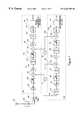
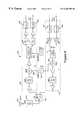
- FIG. 1is a block diagram of a transceiver (receiver and transmitter) module of the base station incorporating some aspects of the present invention.
- the transceiver moduleextracts I,Q baseband signals from received RF signals for further processing in the modem module (FIG. 2 ), and accepts I,Q baseband signals from one or more modem modules for RF transmission.
- FOG. 2modem module
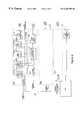
- FIG. 2is a block diagram of the modem module of the base station incorporating some aspects of the present invention.
- the modem moduleaccepts I,Q baseband signals from one or more transceiver modules and processes such signals, such processing including determining signal quality and implementing power control according to various aspects of the invention.
- FIG. 3is a flow diagram of one embodiment of a method for call establishment using minimal transmitted power for a PHS system
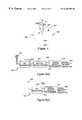
- FIG. 4shows a phase diagram of a typical QPSK signal, including in-phase and quadrature errors
- FIG. 5 ( a )shows an embodiment of an apparatus including spatial processing on which the signal quality aspects of the present invention may be realized
- FIG. 5 ( b )shows another embodiment of an apparatus on which the signal quality aspects of the present invention may be realized
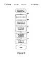
- FIG. 6is a flow diagram for a method for obtaining a signal quality estimate in an angle-modulated communication systems
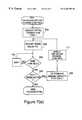
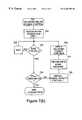
- FIGS. 7 ( a ) and 7 ( b )each shows a flow diagram for one embodiment of a combined initial and on-going power control method.
- FIG. 7 ( a )is applicable on the uplink and
- FIG. 7 ( b )is applicable on the downlink;
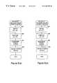
- FIGS. 8 ( a ) and 8 ( b )each shows a flow diagram for one embodiment applying the on-going power control, for example, in the methods shown in the respective flow charts of FIGS. 7 ( a ) and 7 ( b ).
- FIG. 8 ( a )is applicable on the uplink and
- FIG. 8 ( b )is applicable on the downlink;
- FIG. 9illustrates the RF sections of the wireless telephone subscriber unit (SU) with which the SU parts of the invention preferably are implemented.
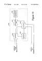
- FIG. 10is a block diagram of the digital signal processor (DSP) section of the SU with which the SU parts of the invention preferably are implemented.
- DSPdigital signal processor
- the methods of the inventionmay be implemented on any communication system which includes one or more communication stations and one or more remote receivers (for communication on the downlink) and transmitters (for communication on the uplink).
- the only requirement for the quality estimation aspects of the inventionis that the modulation used includes some form of angle (e.g., phase) demodulation, and the only requirement for the downlink SDMA power control is the ability to determine downlink transmit weights, for example from received uplink signals.
- the methods of the inventionpreferably are implemented on a communication station which is a base station and on its subscriber units, which are part of a communication system in which a base station uses SDMA to communicate with its subscriber units.
- the communication systemis meant for use in a wireless local loop (WLL) cellular system. While the subscriber units in the illustrative embodiment are fixed in location, in other systems, they may be mobile.
- WLLwireless local loop
- the SDMA base stationfirst is described.
- a multi-element antenna arrayis used in the base station in order to provide spatial processing.
- the number of antennas in the arrayis variable.
- the downlink chain of the base stationincludes a processor for spatially processing coupled to a set of antenna transmit apparatuses, each coupled to one of the antenna elements.
- the uplink chain of the base stationincludes a set of antenna receive apparatuses each receiving a signal from one of the antenna elements, with the antenna receive apparatuses coupled to a processor for spatially processing the received signals.
- communication between base stations and subscriber unitsuses the standard known as “Personal Handyphone System” (PHS), ARIB Standard, Version 2 (RCR STD-28).
- the PHS systemis an 8-slot TDMA/FDMA system with true time division duplex (TDD).
- Each frequency channel (“subcarrier”)has an approximate bandwidth of 300 kHz.
- the 8 timeslotsare divided into 4 transmit (TX) timeslots and 4 receive (RX) timeslots. This implies that for any particular channel, the receive frequency is the same as the transmit frequency. It also implies reciprocity; i.e., the radio propagation path for both the downlink (from base station to users' remote terminals) and the uplink (from users' remote terminals to base station) is identical, assuming minimum motion of the subscriber unit between receive timeslots and transmit timeslots.
- the frequency band of the PHS system used in the preferred embodimentis approximately 1895 to 1920 MHz.
- Each of the 8 timeslotsis 625 microseconds long.
- the PHS systemhas a dedicated frequency and timeslot for a control channel on which call initialization takes place. Once a link is established, the call is handed to a service channel for regular communications. Communication occurs in any channel at the rate of 32 kbits per second (kbps), called full rate. Less than full rate communication is also possible.
- a burstis defined as the finite duration RF signal that is transmitted or received over the air during a single timeslot.
- the PHS systemuses ⁇ /4 differential quaternary phase shift keying ( ⁇ /4 DQPSK) modulation for the baseband signal.
- ⁇ /4 DQPSKdifferential quaternary phase shift keying
- the baud rateis 192 kbaud. That is, there are 192,000 symbols per second.
- the base stationuses an antenna array of antenna elements, and for each antenna, a transmit/receive (T/R) switch, an analog receiver, a digital receiver, a digital transmitter, and an analog transmitter.
- T/Rtransmit/receive
- this moduleincludes part of the antenna transmit apparatuses and part of the set of antenna receive apparatuses.
- the analog and digital receiver and transmitter for any antenna elementare implemented in a single RF TX/RX transceiver module, so that each module implements a one antenna 16 carrier wide band radio spanning 10 MHz of spectrum.
- the architectureis fairly standard, and several variations are possible, as would be clear to those of ordinary skill in the art.
- the particular architecture used for the receiver part of a transceiver moduleis shown in FIG. 1 .
- the RF signalis received at antenna element 103 , and passes via a band pass filter (BPF) 104 , implemented as a cavity filter with a 1895 to 1920 MHz band pass.
- BPFband pass filter
- Antenna 103 and filter 104are external to the transceiver module.
- the signal from filter 104goes to a transmit/receive (T/R) switch 105 on the transceiver module.
- the signalpasses to a low noise amplifier (LNA) 107 , one or more stages of band pass filtering (not shown) and a variable attenuator 108 to a first downconverter 109 , the downconverter using a tunable mixer using a local oscillator 111 (not part of the module) of approximately 1.6328 GHz to produce a first IF signal 113 at 275-285 MHz (10 MHz bandwidth).
- This first IF signal 113is amplified in a first IF amplifier 115 and then passes through a SAW BPF filter 117 (275-285 MHz) that suppress “adjacent channels” and the byproducts of the first downconverter.
- the resulting signal 118passes through a second variable attenuator 119 to a second downconverter 120 using a mixer with a tunable mixer frequency of 291 MHz from a local oscillator 121 .
- the output of the second downconverter 120is a second IF signal 122 at ⁇ (6-16) MHz IF frequency with a 10 MHz bandwidth and a center frequency of ⁇ 11 MHz.
- This second IF signal 122is amplified in a second IF amplifier 123 and a low pass filter (LPF) 125 to an analog to digital converter (ADC) 127 which samples the signal at 36.864 MHz.
- LPFlow pass filter
- signal 129the output of ADC 127 , contains the complex values IF signal centered at ⁇ 11 MHz together with an image at +11 MHz, and sampling produces also an image at 25.864 MHz.
- This signalnow passes through a digital downconverter/filter device 131 implemented with an Analog Devices, Inc. (Norwood, Mass.) AD6620 Dual Channel Decimating Receiver. In alternate implementations, a similar device, a Graychip, Inc. (Palo Alto, Calif.) GC1011 may be used, or the functionality may be otherwise provided for.
- Digital downconverter/filter device 131performs several functions:
- digital bandpass filteringwith a desired bandpass of 300 kHz, currently implemented as an approximately 450 kHz bandpass filter, centered at any of the center frequencies of each of the carriers.
- each such RX/TX boardhandles 16 received carriers, each carrier having its own AD6620 digital downconverter/filter device.
- Each AD6620 devicethus generates 16 bits of I data and 16 bits of Q data, each at 576 ksamples/sec.
- the datais clocked out of each AD6620 device in series at 18.432 MHz. This data goes to the modem board.
- Each modem boardincludes a single general purpose processor (GPP) 203 (a Motorola/IBM PowerPC device) controlling two RX blocks and two TX blocks, each RX block 205 including a RX data formatter 207 , four RX digital signal processor devices (DSPs), denoted 209 . 1 , 209 . 2 , 209 . 3 , and 209 . 4 , respectively, and four RX DSP memories denoted 211 . 1 , 211 . 2 , 211 . 3 , and 211 . 4 , respectively, which are connected to the four RX DSPs.
- GPPgeneral purpose processor
- DSPsdigital signal processor devices
- Each TX block 217includes a TX processor modulator block 221 , and a TX data formatter 225 (implemented using a FPGA).
- Each RX and TX block paircan handle the receive spatial processing, demodulation, modulation, and transmit spatial processing for one carrier in a twelve antenna system, or for two carriers in a six antenna system, or three carriers in a four antenna system.
- one modem boardcan handle the necessary processing for two carriers in a twelve-antenna system, or for four carriers in a six-antenna system, or six carriers with a four-antenna system.
- a single RX block 205 of a modem boardis now described.
- the series I,Q data from the receive part of the transceiver of each antennais passed to a data formatter 207 implemented as a field programmable field array (FPGA), which converts the serial stream to parallel data which is deposited via direct memory access to one of the four RX DSP memories 211 . 1 - 211 . 4 , the data for each of the four receive timeslots going to one RX DSP memory to be processed by the associated RX DSP ( 209 . 1 - 209 . 4 ).
- the RX DSPs 209 . 1 - 209 . 4are each a Motorola M56303 digital signal processor. Each RX DSP performs several functions, including:
- the demodulated signals output from each timeslot RX DSP 209 . 1 - 209 . 4go to a signal bus, called the voice bus 231 , except for certain control signals that go to the GPP 203 via a host port interface.
- the signal quality estimates determined in RX-DSPs, the SINR data sent by a remote user, and some status informationalso are sent to GPP 203 .
- the spatial processing weights determined by each RX DSPgo to TX processor/modulator block 221 in transmit block 217 via a transmit weight (TX_Wt) bus 233 . Transmit power adjustments as part of power control are carried out by adjusting the transmit weights.
- GPSgeneral-purpose processor
- Transmit block 217operates as follows.
- TX processor/modulator 221accepts voice data from voice bus 231 , SACCH and FACCH data from GPP 203 and transmit weights for spatial processing from TX_Wt bus 233 .
- the functions of TX processor/modulator 221include burst building, encryption, scrambling, CRC for each of the users being spatially multiplexed in each of the four timeslots, modulating, and applying complete transmit weights (including the amplitude as power control) for each burst just as the burst starts.
- Transmit block 217can handle four total spatial channels.
- the transmit weight applying partcarries out the complex transmit weight calculation for up to 12 transmitting antennas (i.e., a twelve element antenna array), and for up to four spatial channels. This results in up to 12 digital signals, each having an I & Q component.
- the outputs of TX processor/modulator 221are serialized into up to twelve different serial data streams (I followed by Q) for each of the up to twelve antennas, each I,Q pair going to one RX/TX transceiver module.
- TX processor/modulator 221includes a DSP device, memory and a FPGA.
- the transmit part of the transceiver moduleis now described with the aid of FIG. 1 .
- the transmit partcan handle 16 carriers of 300 kHz bandwidth for a total bandwidth of 10 MHz.
- the incoming 2*upsampled baseband signal from each carriergoes to one of four Graychip, Inc.
- GC4114 quad digital upconverter/filter deviceseach device handling four carriers, for a total of four GC4114 devices on one transceiver module.
- One channel of one GC4114 deviceis shown in FIG. 1 as digital upconverter/filter 151 .
- Signal 155is now fed into an upconverter 157 using a mixer with a tunable mixer frequency of 291 MHz from a local oscillator 121 to produce IF signal 159 at 275-285 MHz (10 MHz bandwidth).
- local oscillator 121is external to the transceiver module.
- Signal 159now passes through a digitally variable attenuator 161 and then passes through an IF strip comprising two SAW filters and two IF amplifiers, shown for simplicity in FIG. 1 as a single BPF filter 163 and single IF amplifier 165 .
- the filtered and amplified IF signalgoes through upconverter 167 , the upconverter comprising a tunable mixer using a local oscillator 111 (external to the module) of approximately 1.6 GHz to produce the approximately 1900 MHz RF signal 169 .
- RF signal 169goes through BPF 171 and then a digitally variable attenuator 173 .
- This signalpasses through a power amplifier (PA), a BPF and a second PA, then through a LPF.
- PApower amplifier
- FIG. 1this combination of PAs and filters is shown in FIG. 1 as a single power amplifier 175 and a single BPF 177 to produce the signal 179 that goes to T/R switch 105 .
- the signal from switch 105goes to the antenna element 103 as described for the receive part.
- the Subscriber UnitThe Subscriber Unit
- FIG. 9illustrates the RF sections of the wireless telephone subscriber unit (SU) with which the SU parts of the invention preferably are implemented, these RF sections referred to herein by the general reference numeral 910 .
- RF sections 910include a receiver front end 912 and a transmitter final stage 914 each connected to an antenna 916 through a bandpass filter 918 and a transmit/receive (T/R) switch 920 .
- T/Rtransmit/receive
- the received signalsgo through a typical downconversion using a 1658 MHz first local oscillator 922 connected to a first intermediate frequency (IF) mixer 924 that produces an IF of 248.45 MHz.
- IFintermediate frequency
- the in-phase (I) and quadrature (Q) signalsare separated by an I,Q demodulator 926 connected to a second local oscillator 928 operating at 469.9 MHz.
- a typical local oscillatoris crystal controlled and will have an accuracy of about ⁇ 10 parts per million (ppm), or ⁇ 20 kHz at the 1.9 GHz RF carrier frequency.
- the local oscillators in the present inventionare preferably of the phase locked loop (PLL) type so that the initial crystal frequency errors can be largely mitigated out by adjusting a voltage controlled oscillator (VCO) once the control channel is acquired.
- PLLphase locked loop
- VCOvoltage controlled oscillator
- a 20 kHz errortranslates to a phase error of 37.5 degrees over the duration of one symbol period.
- decision-directed carrier recoveryin demodulating DQPSK signals as used in PHS. If noise is present, a decision-directed carrier recovery method will likely break lock, unless an initial coarse frequency correction is applied.
- the particular p/4 QPSK demodulation used in the PHS embodimentwhen the frequency offset phase error reaches 45 degrees over the symbol period duration, the decision direction frequency offset estimation will break lock completely, and the bit error rate (BER) will skyrock
- I-ADCin-phase analog-to-digital converter
- Q-ADCquadrature phase analog-to-digital converter
- the transmitted signalsgo through a typical up-conversion using the 1658 MHz local oscillator 922 connected to a final radio frequency (RF) mixer 934 .
- the in-phase (I) and quadrature (Q) signals to be transmittedare received as a stream of 8-bit I-samples at a rate of 768 kilosamples/second by an in-phase digital-to-analog converter (I-DAC) 936 , and as a stream of 8-bit Q-samples at the rate of 768 kilosamples/second by a quadrature phase digital-to-analog converter (Q-DAC) 938 .
- I-DACin-phase digital-to-analog converter
- Q-DACquadrature phase digital-to-analog converter
- FIG. 10is a block diagram of a digital signal processor (DSP) section 1040 that receives the I/Q-samples from the receiver front end 912 and that produces the I/Q-signals to be sent out by the transmitter final stage 914 .
- the DSP section 1040includes several DSP devices, including a receiver-DSP (DSP(RX)) 1042 that is connected to a voice encoding DSP device (vocoder) DSP 1044 and a telephony interface 1046 .
- a transmitter-DSP (DSP(TX)) 1048receives voice/data from the interface 1046 and encodes them into the proper I/Q-signals for transmission by the transmitter final stage 914 .
- a fast memory 1050supplies program execution and support memory for the DSP(RX) 1042 and DSP(TX) 1048 .
- a Motorola (Phoenix, Ariz.) DSP56303 24-bit digital signal processoris used for each of the DSP(RX) 1042 and DSP(TX) 1048 .
- the DSP56303is a member of the DSP56300 core family of programmable CMOS DSPs. Other DSP devices or microprocessors may be substituted, as would be clear to one of ordinary skill in the art.
- RF signals with carriers at approximately 1900 MHzare used to produce in-phase (“I”) and quadrature (“Q”) components that are detected using a 469.9 MHz carrier.
- the I and Q signalsare digitized and sampled at four times the symbol rate.
- the symbol rateis 192 kHz, so the sampling rate in this example would be 768 kilosamples/sec. Each sample is 8-bits deep.
- the received digital I and Q signalsare digital-signal processed by the DSP(RX) 1042 .
- the DSP(RX) 1042is preferably programmed to:
- control-channel acquisition and processing fundamental to time-division duplexingdo the initial estimation of channel-control-data burst timing, and do the initial carrier frequency offset determination
- the baud aligned I and Q samples determined by DSP(RX) 1042are used by DSP(RX) 1042 for estimation of the SU received signal quality (the SU received signal to interference-plus-noise ratio) in one aspect of the present invention
- CRCcyclic redundancy checks
- VCOsvoltage control oscillators
- PLLphase lock loop
- the power for transmitting to the BS as determined according to aspects of the present inventionis adjusted using SDP(TX) 1048 .
- the particular receiver, transmitter, and signal processing described herein for the base station and/or for the subscriber unitis only one possible structure, and many variations are possible without deviating from the invention.
- the final downconversion, or upconversionneed not be carried out digitally.
- the particular DSP structuremay be substituted by microprocessors or other general-purpose processors, or by dedicated hardware.
- many other communication protocolsmay be used in place of the PHS.
- the inventionis not restricted to TDMA/FDMA systems.
- each base stationalso called a cell station (CS)
- CScell station
- SUssubscriber units
- SUremote terminal or personal station
- Each BSincludes a multi-element antenna array in order to provide spatial processing.
- the BSdesiring a connection with a particular SU, sends a paging signal to the selected SU on a control channel of the selected PS, called the paging channel (PCH); 2. the selected SU responds by sending a link channel establishment request to the BS on a control channel called the signaling control channel (SCCH); 3. the BS responds to the link channel establishment request from the SU by selecting a traffic channel (TCH) and sending to the SU on the SCCH information about the selected TCH, the TCH in this case called the link channel (LCH); 4.
- PCHpaging channel
- SCCHsignaling control channel
- TCHtraffic channel
- LCHlink channel
- the selected SUswitches to the assigned LCH and transmits a se- quence of synchronization (SYNCH) burst signals followed by a sequence of idle traffic bursts; and 5. upon successful detection of a synchronization signal (SYNCH burst) from the SU, the BS responds by transmitting a sequence of SYNCH bursts on the LCH followed by a sequence of idle traffic bursts, and then proceeds to establish a connection with the incoming call to the BS, invoking any additional signaling that may be required (e.g., encryption and user authentication).
- SYNCH burstse- quence of synchronization
- the PCHis a one-way downlink point-to-multipoint channel on which the BS transmits identical information to all SUs in the paging area.
- the SCCHis a bi-directional point-to-point channel that transmits information needed for call connection between the BS and a SU.
- the TCHis a point-to-point bidirectional channel for transmitting user (subscriber) information.
- the link establishment procedure of Table 1does not include any power control, for example to ensure the use of minimal transmitter power levels adequate for each connection, and does not address the impact on existing subscribers of interference that would result from the new connection.
- Such power controlis especially critical when bringing up a spatial channel call on a conventional channel already occupied by an existing user.
- one embodiment of the power control method of the present inventionincludes having the SU introduce a set of trial SU transmitter power levels in step 4 of the protocol of Table 1.
- the initial power level used by the SU to transmit a synchronization (SYNCH) burst in step 4is set at a prescribed safe low level that generally would not be sufficient for acceptable quality reception by the BS.
- SYNCH burst replystep 5 , Table 13 indicates to the SU that a SYNCH burst was not received at the BS with acceptable quality, and thus that its SYNCH burst transmission power level was too low.
- the SUthen increases the power level and retransmits a SYNCH burst, and so retransmits each time no SYNCH burst is received from the BS as would be expected in step 5 .
- the BSfinally receives a SYNCH burst from the SU at an acceptable quality, it transmits a SYNCH burst to the SU, so that when a BS-transmitted SYNCH burst finally is received at the SU, the minimal transmitted power level sufficient for communications is being used by the SU.
- the SU transmitter power level requiredis determined at the BS from the number of +3 dB power increments that were made in the elapsed time between the link channel assignment (step 3 , Table 1) and when the SU transmitted SYNCH burst was received at a sufficient quality at the BS. This also can be used to set the BS transmitted power level.
- the PHS systemis a time-division-duplex (TDD) system, so there is substantially reciprocity of transmit and receive propagation paths.
- the BScan use the SU transmitter power level to determine the minimum transmitter power level to be used by the BS for communicating with the SU (i.e., after taking into consideration any differences in SU and BS receiver sensitivity).
- the difference in transmit and receive propagation pathsmay be accounted for by performing on-air measurements and calibrating.
- connection protocolWhen a connection request originates with a SU, the connection protocol is the same as that of Table 1, but excluding step 1 of paging from the BS. Thus, modification for including power control to set minimal transmitting power is the same as described above.
- the advantage of the above described method of power controlis that it may be applied to an existing communication system without adversely impacting communication system protocols that are in existence.
- Two embodiments of the methodinvolve two ways of determining at the BS whether the received signal quality is acceptable.
- a measure of received signal qualityis used at the BS to determine successful reception of the SYNCH burst.
- the second embodimentincludes recognizing that part of a SYNCH burst that is unique to such a burst.
- a SYNCH burstis 224-bit long and includes a 62-bit preamble and a 32-bit “Unique Word” sequence, both of which are prearranged, as well as a BS identification code and a SU identification code.
- the BSmay determine successful reception by correctly recognizing a SYNCH burst. This can be done in addition to, or instead of using a measure of signal quality.
- Table 2shows the specification of a standard 224-bit duration SYNCH burst as used in the preferred embodiment for uplink (SU to BS) or downlink (BS to SU) synchronization. Each of the patterns is shown in order.
- FIG. 3is a flow chart that summarizes a preferred embodiment initial power control method 301 for adaptively determining the adequate power level for acceptable communications.
- the method of the flow chart of FIG. 3is designed to be compatible with the connection protocol for PHS, and does not require any modification to the PHS standard other than simple additions that provide downward compatibility.
- the method of flow chart 301 for adaptive power controlis presented in two versions depending on whether or not the BS is an originator of a connection request. This is shown by decision 303 , which checks if the BS is the originator. If so, the method starts with step 305 in which the BS pages the selected SU on PCH and then moves to step 307 . If the BS is not the originator, the method starts at step 307 .
- selected SUmeans the SU paged by the BS in the case of the BS initiating the connection, and the initiating SU in the case of a SU initiating the connection.
- the selected SUsends a link channel establishment request (LCR) message to the BS on SCCH in response to the page (or, when SU originates, the originating SU sends a LCR message to the BS on SCCH).
- LCRlink channel establishment request
- the BSselects the best candidate link channel (LCH) from the set of traffic channels available and transmit the selection to the SU on SCCH as a tentatively assigned LCH in step 309 .
- the selected SUat step 321 sends a SYNCH burst on the tentatively assigned LCH at a prescribed low power level that is approximately at the lowest possible power level at which acceptable quality reception by the BS might be expected.
- the selected SUchecks if a SYNCH burst has been returned by the BS indicating that last SYNCH burst sent by the SU was received at the BS and the BS transmitted a SYNCH burst in response, this in turn indicating that the SU transmitted with sufficient power to establish acceptable quality reception at the BS. If at step 323 a BS sent SYNCH burst was not received, the SU increments the transmitter power level by a prescribed amount (typically +3 dB) in step 325 and returns to step 321 to again transmit a SYNCH burst. The 3 dB power increments ensure that the power level established in step 325 will be within 3 dB of the minimum power required for quality reception.
- a prescribed amounttypically +3 dB
- the BSlistens on the tentative LCH for the SU originated SYNCH burst transmission, and in step 313 computes the received signal quality as a signal-to-interference-plus-noise-ratio (SINR).
- SINRsignal-to-interference-plus-noise-ratio
- the BSdetermines if the SYNCH burst is received with acceptable quality.
- the BSwaits for the next SYNCH burst from the SU.
- the BScomputes (in step 317 ) the BS transmitting power level, the determination based on the time elapsed between the BS LCH assignment in step 309 and the receipt of an acceptable quality SYNCH burst in step 315 .
- the power used by the SU transmitter for the received SYNCH burstmay be determined, and for the +3 dB increments of the preferred embodiment, is 2 M ⁇ 1 P 0 where M is the number of power increments and P 0 is the prescribed initial SU transmitter power in linear scale (e.g., in Watts).
- the BStransmits a SYNCH burst using a power level based on the computations of step 317 .
- the selected SUupon receiving the BS SYNCH burst, recognizes that the last power level used is adequate for establishing a connection and the process ends.
- the successful reception of the SYNCH burstcan be used as an optional indication that the received signal quality is acceptable and that the transmitter power level used by the SU to transmit the received SYNCH burst is adequate. If this option is selected, the computation of the received uplink SINR in step 313 of FIG. 3 may be omitted and the test in step 315 is answered affirmatively if the SYNCH burst bit pattern is correctly received.
- GSMGlobal System for Mobile Communications
- DCS-1800DCS-1800
- PCS-1900PCS-1900 standard for personal communication systems
- Another aspect of the present inventionis a method for continuing this initial power control by controlling transmitter power on an ongoing basis in order to deal with the dynamic nature of the communication system, and that are applicable to SDMA systems.
- a communication systemdynamically changes because of the establishment of new connections, the dropping or hand-off of existing connections, and changing RF propagation conditions. This produces a time-varying environment in which intracell and intercell connections interact. The establishment of new connections can cause unacceptable interference levels on existing connections, while canceling existing connections can reduce interference so that power levels remaining in use may be higher than required to maintain an acceptable quality of communication.
- the goal of ongoing power controlis to maximize the number of users while maintaining communications (as defined by some acceptable signal quality; for example, some target SINR value) for all users.
- some acceptable signal qualityfor example, some target SINR value
- SINR ⁇ SINR targetan acceptable signal quality
- BERbit error rate
- SDMA techniquesspatial processing techniques
- the complete ongoing power control problemcan then be stated as choosing the receive weights and the uplink transmit power (for uplink control) and the transmit weights and the transmit power (for downlink control), the downlink transmit power, for example, indicated by the relative magnitude of the transmit weight vector.
- the goalis to maximize the capacity (number of users with SINR at least some SINR target ). Note that in general, one can state this problem with a different SINR target for each spatial channel/user.
- the tasks of spatial weight determining and power controlare tightly coupled. Any change in RF power on a conventional channel using SDMA will affect the transmit and receive weights assigned to remote users using the same conventional channel and any change in the weights will affect the power required by existing users in order to maintain an adequate communication quality level.
- the optimal solutionrequires the simultaneous solution of the SDMA multiplexing weight assignment problem and the power assignment problem. For example, on the downlink, one would determined the complete transmit weight vector, including the magnitudes, the magnitudes representing the relative transmit power on the particular spatial channel.
- the simultaneous solution of the SDMA multiplexing weight assignment problem and the power assignment problemis at the very least an involved computational task.
- An aspect of the present inventionis, for the uplink, to separate the uplink joint spatial multiplexing and power control problem into two parts: a receive weight determining part and a power adjustment part.
- the methodstarts with one part, for example power control.
- a power control strategyis used, and the transmit powers according to this initial strategy are assigned.
- Spatial receive weight assignmentis now carried out with these assigned transmit powers.
- the resulting new spatial weights at firstaffect interference levels so that the initial power assignment may no longer be appropriate.
- the ongoing power control techniqueis again applied, leading to new power assignments.
- These new power assignmentsmay mean that the receive and transmit weights are no longer optimal, so that the new transmit powers are used as initial conditions for new transmit and receive weights to be determined.
- spatial weights and power controlare jointly determined.
- every new power control assignment and every new transmit weight assignmentis used immediately after the other is determined.
- the environmentis constantly changing.
- a complete transmit weight vectorcan be thought of as a set of relative transmit weights, all scaled by a particular scaling factor, so that determining a complete transmit weight vector simultaneously solves the problem of what relative transmit weights to use for transmitting to a particular remote user, and how much power to transmit with, the power given by the scaling applied to the relative transmit weights to form the complete weight vector.
- Another aspect of the present inventionis, for the downlink, to separate the complete transmit weight vector determination problem, which includes power control, into two parts: a relative transmit weight vector determining part and a power adjustment part which determines the scaling to apply to the relative transmit weight vector.
- the methodstarts with one part, for example power control. A power control strategy is used, and the transmit powers according to this initial strategy are assigned.
- Relative transmit weight determinationis now carried out with these assigned transmit powers.
- the resulting new relative transmit weight vectorat first affect interference levels so that the initial power assignment may no longer be appropriate.
- the ongoing power control techniqueis again applied, leading to new power assignments.
- Uplink power controlis first described with the help of FIG. 7 ( a ), which shows ongoing uplink power control method 701 .
- step 703some power is used by each SU. How to set up initial SU power assignments in the preferred embodiment is described above in the “Initial Power Control” section and in the Parent Patent.
- a set of uplink (i.e., receive) weight vectorsare determined at the base station.
- the uplink (receive) weight vectorsare determined in step 704 (shown for a spatial channel i) by a method substantially as described in Our Demodulation Patent, incorporated herein by reference. Note that in the preferred embodiment, these uplink weights are used by the BS to determine downlink weights.
- the systemuses time division duplexing (TDD) and the uplink and downlink frequencies are identical for the same user.
- TDDtime division duplexing
- the uplink weightsare used to determine downlink weights according to methods substantially as described in above mentioned U.S. Pat. No. 5,592,490 and in Our Calibration Patent (U.S. application Ser. No. 08/948,772, Oct. 10, 1997), both these incorporated herein by reference.
- uplink weightsaffects the signal quality (e.g., the SINR) of the received BS (uplink) signals, so that new power control may need to be applied.
- Such ongoing power controlis applied periodically at the base station.
- ongoing power controlis applied after a pre-specified time period has elapsed, and this time period preferably is two frames in this embodiment.
- this time periodpreferably is two frames in this embodiment.
- step 708If it is time to apply the power control, before such control is applied, it is determined in step 708 if the call on the spatial channel should be or has been be reassigned to another channel, or should or has been handed over to another base station. If yes, the power control for this call on this spatial channel is terminated, and this is shown by the block labeled “END i CONNECTION” in FIG. 7 ( a ). Otherwise, in step 709 , one determines the signal quality (SINR) of the received signal at the base station. This signal quality (preferably SINR) is estimated in the preferred embodiment using the methods described below in the “Signal Quality Estimation” section of this description, (e.g., by use of Equation (20) and FIGS. 5 and 6 ).
- SINRSignal Quality Estimation
- step 711the new amounts by which to ramp the uplink powers up or down are determined in step 711 for spatial channel i. See below for a description of some methods for step 711 .
- the power control according to step 711is carried out by commanding the remote subscriber unit (remote transmitter) on spatial channel i.
- the SUtransmits with these new uplink powers, and one now returns to step 704 of determining new uplink (receive) weights at the BS. If insufficient compute power precludes step 704 from being performed in the current burst or the current power control period, it may be done at the next burst or the next power control period. This closes the loop.
- the new uplink signalsare used to determine the downlink weights and thus affect downlink communication.
- FIG. 7 ( b )shows a flow chart of the preferred embodiment ongoing power control method 721 .
- transmit weightsinitially are those determined from uplink weights which in turn are determined from uplink signals after communications is established.
- the transmit weightspreferably are normalized and thus are relative transmit weights. Alternate embodiments may use other methods to determine weights; e.g., one may determine directions of arrivals and perform beamforming, as is known in the art (see, for example, above-mentioned U.S. Pat. Nos. 5,515,378 and 5,642,353).
- the results of all such methodswill be described herein as weighting by a relative transmit weight vector, and the scaling of such a relative transmit vector is the preferred way of applying the power control.
- the initial power to use on the downlink on a particular spatial channel (i) to a particular SU (remote receiver)is determined and applied in step 723 using an initial power control method, preferably the method of the Parent Patent.
- the relative transmit weight vector of these initial relative transmit weights for the particular SU on the spatial channelis used to transmit at the initial transmit power level, resulting in signal received at the particular SU with some downlink signal quality (e.g., SINR).
- SINRdownlink signal quality
- Estimates of these downlink SINRsare determined at the SUs, preferably using the method described below, and periodically sent to the BS.
- each SUperforms the estimation and sends its signal quality estimate to the base station every frame. Other embodiments may do so as different intervals.
- the ongoing downlink power control methodlike the uplink method, is applied periodically at the base station. In the preferred embodiment, this period is every two frames, and other embodiments may use other update periods.
- step 725 for a particular spatial channel iit is determined if it is time to apply the power control, and if not, the base station waits until the next period.
- step 728if the call on spatial channel i should be or has been reassigned to another channel, or should or has been handed over to another base station. If yes, the power control for this call on this channel is terminated, and this is shown by the block labeled “END i CONNECTION” in FIG. 7 ( b ). Otherwise, the downlink signal quality estimate received from the particular SU is obtained (step 729 ) for use by the method and this signal quality estimate is used in step 733 for downlink power control. See below for a description of some methods for step 733 .
- the power control according to step 733is carried out by modifying the relative transmit weights to determine actual transmit weights to use, the modification modifying the magnitudes of the relative transmit weights for any particular SU; i.e. modifying the norm of the vector of relative transmit weights.
- the relative transmit weightsmay be the same weights as previously used if no weight updating has occurred, or updated relative weights of if updated weights are available.
- step 731 in the flow chartshows obtaining such (new) SDMA relative transmit weights prior to applying the ongoing power control step 733 .
- step 731 of obtaining updated values of the relative transmit weight vectormay occur in other points in the flow chart, and step 733 preferably uses the latest update of the relative transmit weights.
- uplink and downlink controlwere described above as being separate, in the preferred embodiment where uplink signals and/or weights are used to determine downlink weights, uplink and downlink control is not quite partitioned.
- the initial downlink weights and powersare based on those determined in uplink power control and weight determination.
- steps 711 and 733 for the uplink and downlink, respectivelyare now described.
- Several methods for carrying out a power assignment stepsuch as steps 711 for the uplink and step 733 for the downlink are known for conventional cellular systems, and many of these methods may be easily adapted for use in implementing the present invention.
- the inventionis not restricted to only using the below described methods for steps 711 and 733 .
- p ithe transmit power for the ith transmitter (in a SU for uplink or in a BS for downlink) in the communication system.
- all power quantitiesare in a natural scale (e.g., power measurements are in Watts, not dB).
- the taskis to determine (separately on the uplink and on the downlink) the powers p i (positive) for all i (i.e., all transmitters) that minimize for the whole system (on the uplink, or on the downlink) the total power.
- subscript iindicates the ith transmitter, whether uplink (a SU) or downlink (a base station)
- p ithe transmit power for the ith transmitter
- c ia positive parameter indicating the relative weight of the transmit power for the ith transmitter.
- the criterionis to find the powers that minimize the total power.
- interfering usersmay be intercell or intracell users or both.
- downlink determinationin step 733
- G ijis path loss (and/or gain) for the path from transmitterj to receiver i.
- the transmitteris a SU and the receiver is a BS, while on the downlink, the transmitter is the BS and the receiver is the SU.
- G ijincludes the RF path loss experienced between transmitter j and receiver i, the spatial processing rejection or gain factor, and any other attenuation or gain factor along the path from transmitter j to receiver i.
- ⁇ i 2as the effective background noise level experienced by the ith subscriber unit (on the downlink) or BS (on the uplink) (after reception and any spatial processing), and define SINR i as the SINR target for receiver i.
- Equations (1) and (2) for non-negative transmit powersmay be recognized as linear programming optimization problems in non-negative variables (the transmit powers). Many methods are known for solving such linear programming problems.
- One well-known method that may be usedis the Simplex method described, for example, in Murty, K. G., Linear Programming, Wiley & Sons, New York, 1983.
- the above globally optimal methodin general requires communications of power control information between base stations of the system.
- the computation timemay be too long relative to the rate of change of connection conditions; and, it may not be feasible or practical to gather the necessary power control information, such as the path gain G ij between every base station and every remote subscriber unit in real time.
- the global objectivemay be simplified to be true within some subset of the overall system, for example, within a particular cell of interest.
- the objective of ongoing uplink power controlis to substantially minimize the total power transmitted by all subscriber units within a cell of a communication system while ensuring that the desired SINR for every connection to the BS within the cell is satisfied.
- the objectiveis to minimize the total power transmitted by the BS to all its SUs while maintaining a target level of communications.
- the resulting uplink and downlink power control methodswherein the objective is simplified to be required within some subset of the communication system, and wherein every subset is allowed to achieve its own objective, is referred to herein as a distributed method.
- the distributed power control strategyonly requires the set of path gains between the base station and each subscriber unit belonging to the same cell. No direct base station to base station (i.e., intercell) communication is required. It is possible that using only distributed, locally optimal decisions will result in globally optimal system behavior.
- the distributed methodincludes breaking up a global optimization problem into many small localized optimization problems which are solved simultaneously at each base station in the communication system, and for each conventional channel on each such base station.
- Method 1for carrying steps 711 and 733 using distributed methods are now described.
- the procedures for both the uplink and the downlinkare at each base station to periodically update the applied power for each subscriber unit (that is, each spatial channel), the updating based on some function of the most recently (typically the presently) applied power, the minimum acceptable signal to interference-plus-noise level (SINR), and the most recently (typically the presently) observed (i.e., estimated) SINR for the spatial channel used in communicating with the SU.
- This signal quality (SINR)is estimated in the preferred embodiment using the methods described below (e.g., by use of Equation (20) and FIGS. 5 and 6 ).
- the updatingpreferably every two frames, and other update periods may be used, as well as different uplink and downlink update periods.
- Kdenote the most recent (say Kth) update of the power control
- superscript idenote a particular subscriber unit
- D and Udenote downlink (i.e., in step 733 ) and uplink (i.e., in step 711 ), respectively.
- all power and power ratiosare assumed in natural (i.e., linear) units (e.g., WATTS) rather than logarithmic units (e.g., dB).
- p i (K)be the transmitted power for the ith user for the Kth update.
- SINR target ibe the minimum acceptable SINR for this user
- SINR estimatorestimate is indicated by the double overbar. Note the above SINR and the p i (K) quantities have the D or U superscripts omitted for simplicity.
- the power control(steps 711 on the uplink and step 733 on the downlink) then is applied as follows from update period to update period.
- the transmitter power of the ith useris updated according to the following iterative rule.
- the updated power to use(the (K+1)′th update) is a function of the target SINR for that user and the previously applied powers and the previous estimates of the SINR for that receiver.
- ⁇ Uis some function.
- p i U ⁇ ( K + 1 )f U ⁇ ( p i U ⁇ ( K ) , SINR i U ⁇ ( K ) _ _ , SINR target i U ) .
- ⁇ Dis some other function.
- p i D ⁇ ( K + 1 )f D ⁇ ( p i D ⁇ ( K ) , SINR i D ⁇ ( K ) _ _ , SINR target i D ) .
- ⁇ D⁇ U .
- p i D ⁇ ( K + 1 )( SINR target i D SINR i D ⁇ ( K ) _ _ ) ⁇ ⁇ p i D ⁇ ( K ) ⁇ ⁇ and (3a)
- p i U ⁇ ( K + 1 )( SINR target i U SINR i U ⁇ ( K ) _ _ ) ⁇ ⁇ p i U ⁇ ( K ) , (3b)
- Equations (3)provide for different target levels of quality of communications for each spatial channel and for the uplink and downlink.
- the target SINRsare the same for all users i and are the same for the uplink step 711 and the downlink step 733 .
- the power controlis to use in the next iteration the power (log scale) used in the most recent iteration plus an increment which is some function of the difference between the target SINR (log scale) and an estimate of the most recently experienced SINR (log scale).
- the functionis proportionality, so that the procedure is to update the applied power based on the most recently (e.g., the presently) applied power and the difference between the minimum acceptable SINR and the estimated SINR (all in log scale).
- P Li ⁇ ( K + 1 )P Li ⁇ ( K ) + ⁇ ⁇ ( SINR Ltarget i - SINR Li ⁇ ( K ) _ _ ) , ( 4 )
- SINR Ltarget imay be different for each spatial channel. For example, when one has both voice and data traffic, for 32 kbps voice as used in PHS (adaptive differential PCM), a SINR Ltarget of 15 dB may be good enough, while for a data channel, the desired BER may be in the order of 10 ⁇ 6 to 10 ⁇ 8 which would correspond to an approximate SINR Ltarget of 21 dB. In the preferred embodiment, the same value, SINR Ltarget is used for all spatial channels.
- the power control step 711 using Equation (4) with superscript Uis carried out for each spatial channel on the uplink
- the power control step 733 using Equation (4) with superscript Dis carried out for each spatial channel on the downlink.
- Equation (4)described adjusting the power according to a linear function of the difference (in log scale, e.g., in dB) between the target and actual estimated SINR
- the method in steps 711 or 733may be generalized to an adjustment of the transmit power (in log scale) according to some (e.g., nonlinear) function (say function fn) of the difference between the target and actual estimated SINR:
- P Li ⁇ ( K + 1 )P Li ⁇ ( K ) + fn ⁇ ( SINR Ltarget i - SINR i ⁇ ( K ) _ _ ) , ( 5 )
- Equation 5the power control (step 711 on the uplink and step 733 on the downlink) using Equation 5 is carried out for all spatial channels at each of the cells of the communication system. No base station to base station communication therefore need be used.
- this methoddoes not require any knowledge of the transmission gains, there is no need to model and/or measure the spatial processing gains, path gains, or distinguish between intracell vs. intercell interference.
- the methodonly requires a reliable SINR estimator such as the carrier modulus moment method described below (the “signal quality estimation” aspect of the invention).
- the second embodiment of the distributed power control problem(steps 711 or 733 ) is to explicitly find a solution to the localized optimization problem for the uplink and for the downlink.
- subscript iindicates the spatial channel
- p iis the transmit power (in linear units) for the ith spatial channel
- c iis a positive parameter indicating the relative weight of the transmit power for the ith spatial channel.
- c i1 for all i so that the criterion is to minimize the total power.
- some spatial channelsmay be more important than others and different values of c i may be chosen to reflect this.
- the predicted SINR when one uses a particular spatial weight (say, on the downlink, w i D ) in spatial channel (denoted i)needs to be at least the value of the target SINR for that spatial channel, for all spatial channels.
- L i Dis the path loss (or gain) for spatial channel i and its associated SU
- I i Dis the downlink post-spatial processing noise-plus-intercell (i.e., out-of cell) interference experienced by subscriber i.
- Equation (7a)is minimized subject to the constraint of Equation (7a), where the quantities are as before with superscript D to indicate the downlink.
- the set of weights, ⁇ w i D ⁇ and ⁇ w i U ⁇ , and the sets of spatial signatures, ⁇ a i D ⁇ and ⁇ a i U ⁇ , of existing connectionsare usually known or can be determined by known methods by the base station(s). See for example, above mentioned incorporated-by-reference U.S. Pat. No. 5,592,490. Any means for so determining these quantities is called a spatial processor herein.
- the path gains, ⁇ L i D ⁇ and ⁇ L i U ⁇ ,can be estimated as follows.
- the RSSIis estimated as E(R 2 ) ⁇ overscore (R 2 ) ⁇ according to Equation (19b) as described below in the description of the “signal quality estimation” aspect of the invention.
- the RSSIis then measured after the receive spatial demultiplexing for each spatial channel. Note that in the preferred embodiment, the RSSI is available at input to the demodulator, a decision feedback demodulator. See above-mentioned incorporated-by-reference U.S. patent application Ser. No. 08/729,390. This is used as before to estimate the signal quality as expressed by SINR.
- L i DRSSI i D p i D ⁇ ( 1 + 1 SINR i D _ _ ) (9a)
- L i URSSI i U p i U ⁇ ( 1 + 1 SINR i U _ _ ) , (9b)
- the p i D and p i Uare the known downlink and uplink transmit power used by the base station associated with the ith subscriber and base station associated with the ith subscriber during each of the last transmitted bursts.
- Equations (9a) and (9b)since one knows the power being transmitted during initial call set up, the path loss can be obtained by measuring the average power at the antennas.
- a pilot toneexists and is continually transmitted at a known power level on the downlink.
- Using a pilot tonecan be used to determine the path loss.
- several methodsmay be used to determine the pass loss.
- I i D ⁇ ( K )RSSI i D ⁇ ( K ) 1 + SINR i D ⁇ ( K ) _ _ - L i D ⁇ ( K ) ⁇ ⁇ j ⁇ i ⁇ ⁇ w j D * ⁇ ( K ) ⁇ a i D ⁇ ( K ) ⁇ 2 ⁇ p j D ⁇ ( K - 1 ) (11a)
- I i U ⁇ ( K )RSSI i U ⁇ ( K ) 1 + SINR i U ⁇ ( K ) _ _ - ⁇ j ⁇ i ⁇ w i U * ⁇ ( K ) ⁇ a j U ⁇ ( K ) ⁇ 2 ⁇
- Equation (7)(as part of downlink step 733 ) and Equation (8) (as part of uplink step 711 ) are each solved at each base station as a linear programming problem. Any known method of solving the linear programming problem may be used.
- Equations (7a) and (8b)are modified to be equality constraints. That is, in the preferred embodiment, one determines the powers in the downlink and uplink, respectively, by solving Equations (7a) and (8a), respectively, with equality constraints. That is, in a conventional downlink channel, the set of powers to apply for downlink communications for the spatial channels in any conventional downlink channel are determined be setting the predicted downlink SINR in each downlink spatial channel of the conventional downlink channel to be equal to a target SINR for that downlink spatial channel. In the preferred embodiment, the target SINR is the same for all downlink spatial channels of the conventional uplink channel.
- the set of powers to apply for uplink communications for the spatial channels in any conventional uplink channelare determined be setting the predicted uplink SINR in each uplink spatial channel of the conventional uplink channel to be equal to a target SINR for that uplink spatial channel.
- the target SINRis the same for all uplink spatial channels of the conventional uplink channel.
- Ais a square matrix of dimension d (the number of spatial channels)
- pis the vector of powers (the superscripts U and D are left out for simplicity)
- bis a vector of target SINRs multiplied by the interference and noise (I i ) quantities.
- channel reassignmentis carried out according to the channel reassignment procedure for the system.
- FIGS. 8 ( a ) and 8 ( b ), respectively,are flow diagrams showing using this second embodiment for steps 711 and 733 , respectively, for uplink and downlink ongoing power control, respectively.
- FIG. 8 ( a )shows such an embodiment 801 of step 711 for applying on-going uplink power control for a given SDMA channel i.
- the processobtains from the spatial processor, for all i, the uplink quantities ⁇ w i U ⁇ and ⁇ a i U ⁇ .
- step 805for all i, using the estimates SINR i U _ _
- step 709the sets of path gains, ⁇ L i U ⁇ , are computed using Equations (9b), and the interference plus noise quantities ⁇ I i U ⁇ also are determined using Equations (10b) or (11b).
- step 807the uplink power assignments are determined, preferably by solving the equality constraint problems (Equations (12b) and (13)).
- step 809the uplink power levels are adjusted in accordance with the solution obtained in step 807 by commanding the SUs to use such powers, and the process ends (returning to step 704 ).
- FIG. 8 (b)similarly shows an embodiment 821 of step 721 for applying on-going downlink power control for a given SDMA channel i.
- step 823the process obtains from the spatial processor, for all i, the downlink quantities ⁇ w i D ⁇ and ⁇ a i D ⁇ . Then, in step 825 , for all i, the sets of path gains, ⁇ L i D ⁇ , are computed using Equations (9a), and the interference plus noise quantities ⁇ I i D ⁇ also are determined using Equations (10a) or (11a).
- step 827the the downlink power assignments are determined, preferably by solving the equality constraint problems (Equations (12a) and (13)).
- step 829the downlink power levels are adjusted in accordance with the solution obtained in step 827 , and the process ends (returning to step 724 ).
- Step 313 of method 301 for initial power controlincluded determining the signal quality.
- both the ongoing power control method using Equations (3) or (4) and the localized power control method explicitly solving Equations (7) and (8)include using an estimate of a measure (the SINR) of the signal quality (see steps 709 and 729 in flow charts 701 and 721 , respectively).
- Another aspect of the inventionis a method for implementing such steps. While any methods for determining these estimates may be used in implementing the power control aspects of the invention, another aspect of the invention is a RF carrier signal quality estimator method and apparatus which is applicable to all angle-modulated RF carriers. Because of the large variety of these angle-modulated systems, the detailed description will be only for one of two types in order to increase understanding of the invention.
- the two sample angle-modulated signals selected for this purposeare a quaternary phase shift keyed (QPSK) signal and a differential quaternary phase shift keyed signal (DQPSK) that are found in wide-spread use in the communication field.
- QPSKquaternary phase shift keyed
- DQPSKdifferential quaternary phase shift keyed signal
- Each symbol in these schemescontains two bits (a dibit) of information.
- the important feature of the phase modulated signal with respect to the signal quality estimation aspect of the current inventionis that the magnitude of the data symbols is assumed to be constant in the absence of noise or other forms of corruption. The number of discrete phase levels (four in these cases) is not important.
- the phase plane of a QPSK signalis the same as the differential phase plane of a QPSK signal, which is the phase plane of the difference in phase between two successive symbols.
- the four symbol points used in the descriptionare 0, ⁇ /2, ⁇ , and 3 ⁇ /2, while in the particular DQPSK used in the preferred embodiment, ⁇ /4 DQPSK, the four symbol points used are, in the differential phase plane. ⁇ /4, 3 ⁇ /4, 5 ⁇ /4 and 7 ⁇ /4 (that is, ⁇ /4 and ⁇ 3 ⁇ 4).
- FIG. 4is a complex phase plane diagram 401 of the four states of a QPSK model, except that an extraneous noise vector, ⁇ S, and resultant phase error, ⁇ , have been added to represent the practical situation in which the presence of noise and interference introduces both amplitude and phase errors into the observed data symbol R.
- Vector ⁇ Scorresponds to the vector difference between the uncontaminated symbol S and the observed symbol R.
- FIG. 4is a complex phase plane representation of a received data symbol signal R on the phase plane. Also shown on the phase plane 401 are the four decision points 403 , 404 , 405 , and 406 at phases 0, ⁇ /2, ⁇ , and 3 ⁇ /2, respectively (the constellation of decisions). Any frequency offsets present may be thought of as rotations of the constellation points relative to the received signal R. R may be thought of as a constant modulus signal S, onto which an extraneous noise vector ⁇ S has been added, resulting in phase error ⁇ . ⁇ S represents noise and interference which in practice is present and introduces both amplitude and phase errors into the observed data symbol R. That is, vector ⁇ S corresponds to the vector difference between the uncontaminated symbol S and the observed symbol R.
- the essence of the preferred embodiment signal quality estimatoris to estimate the SINR of the received signal entirely from observations of radius R over a burst of received data. This exploits the fact that radius R is invariant to rotations of the constellation, thus making the SINR estimate substantially immune to frequency offsets.
- the noise and interference vector, ⁇ Sis modeled as a zero-mean Gaussian random process with independent real (i.e., in phase I) and imaginary (i.e., quadrature Q) components, each component with a variance of ⁇ 2 .
- This modelis chosen because it leads to a realistic and practical method for determining the modulus S and the statistical evaluation of the associated noise and interference vector. While this model is used in explaining the method, the method works for actual signals and noise for which the zero-mean Gaussian random process assumption may not hold.
- SINRsignal-to-interference-plus-noise
- Equations (15)and (16)are two (nonlinear) equations in two unknowns ( ⁇ 2 and SINR).
- one embodiment of the methodis to simultaneously solve Equations (15) and (16) for SINR.
- Values of ⁇ (SINR) accordingmay be pre-stored in a lookup table.
- the approximation ⁇ (SINR) ⁇ 1may be used.
- the complex valued baseband signal for the communications channelpreferably is provided as in-phase and quadrature components, denoted by I and Q, respectively.
- the average of the (I 2 +Q 2 ) values over a set of samplesis a measure of the received signal strength indicator (RSSI), commonly available in receivers.
- RSSIreceived signal strength indicator
- I(n) and Q(n)the sampled values of I and Q
- the on-baud sampling point for a given pulse-shaped symbolcorresponds to the center point in time of the pulse-shaped symbol.
- the on-baud sampling pointcorresponds to the time sample closest to the center of the pulse-shaped symbol.
- successive samples in I(n) and Q(n)are one baud period apart.
- these I and Q valuesare for a single modulated signal of a single (spatial) channel.
- theseare the I and Q values after spatial processing and substantially on the baud points.
- the output downconverter/filter 131are the sampled signals for one antenna only—that is, before spatial processing, and are oversampled. Determining signals I(n) and Q(n) after spatial processing at or close to the baud points is thus assumed to have been carried out, preferably in the corresponding RX DSP 209 . See Our Demodulation Patent (above mentioned U.S. patent application Ser. No.
- an iterative solutionis used in which values of 2 ⁇ 2 and SINR are assumed and substituted into Equation (15) and (16), the computed value of E ⁇ R 2 ⁇ and E ⁇ R ⁇ are compared with the estimated RSSI (R 2 obtained from measurement) and ⁇ overscore (R) ⁇ , respectively, and, if the differences are acceptably small, accepting the substituted values as the solutions that lead to the SINR estimate.
- Thisis a standard iterative way of solving the two simultaneous nonlinear Equations (15) and (16).
- Equation (17a)in order to estimate E ⁇ R ⁇ from measurements, (see Equation (17a)), a square root operation needs to be performed. This is computationally expensive.
- a second preferred methodis based only on using the even powered non-central moments, E ⁇ R 2 ⁇ and E ⁇ R 4 ⁇ , determined according to Equations (17b) and (17c).
- the even powered non-central moments, E ⁇ R 2 ⁇ and E ⁇ R 4 ⁇are the mean power and the mean squared power measurements.
- FIG. 5 ( a )is a block diagram of one realization of a base station apparatus ( 501 ) used for obtaining the signal quality estimates.
- This apparatusis a simplified version of the base station apparatus of FIGS. 1 and 2.
- the apparatus 501is comprised of an antenna array 503 for receiving RF signals, a set of RF receivers 505 (i.e., antenna receive apparatuses) for converting the signals at each of the elements in antenna 503 into a complex valued baseband signals, a spatial processor 507 for determining the baseband signals from a particular remote user preferably provided as in-phase (I) component 509 and quadrature (Q) component 511 , signals 509 and 511 determined substantially at the baud points.
- Iin-phase
- Qquadrature
- each element of antenna array 503 and each RF receiver 505are implemented in the transceiver module shown in FIG. 1, and generate digital pre-spatial processing signals as the outputs of downconverter/filters 131 .
- Spatial processor 507is preferably a programmable digital arithmetic processor. When used in the base station of the preferred embodiment, spatial processor 507 is part of the modem module of FIG. 2, in particular, one of the RX DSPs 209 , the particular RX DSP being the one for the slot being received.
- Signal quality processor 513also is preferably a programmable digital arithmetic processor. When used in the base station of the preferred embodiment, signal quality processor 513 is part of the modem module of FIG. 2, in particular, one of the RX DSPs 209 , the particular RX DSP being the one for the slot being received.
- FIG. 5 ( b )is a block diagram of one realization of a subscriber unit apparatus ( 521 ) used for obtaining the signal quality estimates.
- This apparatusis a simplified version of the subscriber unit apparatus of FIGS. 9 and 10.
- the apparatus 521is comprised of an antenna 523 for receiving RF signals, an RF receiver 525 for converting the signal from antenna 523 into a complex valued baseband signal, preferably as in-phase (I) component 529 and quadrature (Q) component 531 , signals 529 and 531 determined substantially at the baud points.
- the I and Q signals 529 and 531are fed to a signal quality estimator 533 for further processing to produce the desired signal quality estimate, shown as signal quality indicator 535 in FIG. 5 ( b ).
- antenna 523 and RF receiver 525are implemented in the RF system shown in FIG. 9, and generate oversampled I and Q signals.
- Signal quality processor 533also is preferably a programmable digital arithmetic processor. When used in the subscriber unit of the preferred embodiment, signal quality processor 533 is DSP(RX) 1042 , and its function includes determining the samples at the approximate baud points.
- signals 509 and 511in a BS
- signals 529 and 531after baud point processing by DSP(RX) 1042 in the SU
- I(n) and Q(n)respectively, where each successive sample n is at or close to successive baud points.
- the sampled modulus informationis extracted by forming the sum of the squares of the in phase and quadrature signals, that is, the instantaneous power.
- instantaneous power R 2 (n)is obtained using Equation (17b)
- the second and fourth momentsmeans power ⁇ overscore (R 2 ) ⁇ and mean squared power ⁇ overscore (R 4 ) ⁇ , respectively, are estimated by forming the averages of R 2 (n) and R 4 (n) over a moving window.
- Equation (20)is now used to determine the quality estimate. In practice, as would be clear to one of ordinary skill in the art, only the summations in Equation (19b) (and Equation (19c), if used) are formed. The 1/N factor need not be determined for all averages so long as the correct scaling is maintained in the determination of the quality estimate using Equation (20).
- an additional stepis added of taking a moving average of SINRs over several bursts. For example, the Kth running average determined, after K bursts, as
- SINR K⁇ SINR+ (1 ⁇ ) SINR K ⁇ 1 (21)
- SINRis the new measure for the current (Kth) burst
- SINR Kdenotes the Kth running average of the SINR.
- the value of ⁇is selected to control the rate of adaptation of the moving average to changing conditions. In the preferred embodiment of a PHS system, a value of 0.8 is used for ⁇ .
- the running average of Equation (21)is easily implemented as a finite impulse response (FIR) filter, and does not add much to the computational burden, as the data rate (a new SINR every burst) is low.
- the moving averagepreferably is implemented in signal quality processor 513 (in a base station) and processor 533 (in a SU).
- FIG. 6is a flow diagram for method 601 that summarizes the method for obtaining a signal quality estimate in angle modulated communication systems.
- step 603an angle-modulated signal is received.
- step 605generates the in-phase (I) and quadrature (Q) components of the received signal in baseband, after spatial processing in the case of SDMA, and substantially at the baud points in the case of digital processing.
- Step 607extracts estimates of at least two distinct moments of the modulus of the received signal from the I,Q components, and step 609 determines averages of the moments.
- Step 611determines the signal quality estimate as the SINR estimate.
Landscapes
- Engineering & Computer Science (AREA)
- Computer Networks & Wireless Communication (AREA)
- Signal Processing (AREA)
- Quality & Reliability (AREA)
- Physics & Mathematics (AREA)
- Electromagnetism (AREA)
- Mobile Radio Communication Systems (AREA)
- Transmitters (AREA)
- Variable-Direction Aerials And Aerial Arrays (AREA)
- Cable Transmission Systems, Equalization Of Radio And Reduction Of Echo (AREA)
Abstract
Description


| TABLE 1 |
| PHS |
| 1. | the BS, desiring a connection with a particular SU, sends a paging |
| signal to the selected SU on a control channel of the selected PS, | |
| called the paging channel (PCH); | |
| 2. | the selected SU responds by sending a link channel establishment |
| request to the BS on a control channel called the signaling control | |
| channel (SCCH); | |
| 3. | the BS responds to the link channel establishment request from the |
| SU by selecting a traffic channel (TCH) and sending to the SU on the | |
| SCCH information about the selected TCH, the TCH in this case | |
| called the link channel (LCH); | |
| 4. | the selected SU switches to the assigned LCH and transmits a se- |
| quence of synchronization (SYNCH) burst signals followed by a | |
| sequence of idle traffic bursts; and | |
| 5. | upon successful detection of a synchronization signal (SYNCH burst) |
| from the SU, the BS responds by transmitting a sequence of SYNCH | |
| bursts on the LCH followed by a sequence of idle traffic bursts, and | |
| then proceeds to establish a connection with the incoming call to the | |
| BS, invoking any additional signaling that may be required (e.g., | |
| encryption and user authentication). | |
| TABLE 2 | ||||
| Name | Description | |||
| R | ||||
| 4 bits | any 4 bit pattern | |||
| SS | 2 bits | fixed field 10 | ||
| PR | 62 bits | a fixed periodic preamble for both uplink and | ||
| down link 0110011001100110 . . . 011001 | ||||
| UW | 32 bits | Unique Word, which for designating uplink | ||
| synchronization is | ||||
| 01101011100010011001101011110000 | ||||
| and for downlink synchronization is | ||||
| 01010000111011110010100110010011; | ||||
| 4 bits | fixed field 1001 | |||
| CSID | 42 bits | BS identification code | ||
| PSID | 28 bits | SU identification code | ||
| IDL | 34 bits | all zeros, | ||
| CRC | 16 bits | cyclic redundancy code error detection. | ||


Claims (52)


Priority Applications (11)
| Application Number | Priority Date | Filing Date | Title |
|---|---|---|---|
| US09/020,049US6463295B1 (en) | 1996-10-11 | 1998-02-06 | Power control with signal quality estimation for smart antenna communication systems |
| JP2000530987AJP2002503053A (en) | 1998-02-06 | 1999-02-03 | Power control with signal quality estimation for smart antenna array communication system |
| AU24942/99AAU2494299A (en) | 1998-02-06 | 1999-02-03 | Power control with signal quality estimation for smart antenna array communication systems |
| DE69916579TDE69916579T2 (en) | 1998-02-06 | 1999-02-03 | POWER CONTROL WITH SIGNAL QUALITY ASSESSMENT FOR COMMUNICATION SYSTEMS WITH INTELLIGENT ANTENNA GROUPS |
| CN2007100054001ACN101026398B (en) | 1998-02-06 | 1999-02-03 | Power control with signal quality estimation for smart antenna array communication systems |
| CNB998026123ACN1310439C (en) | 1998-02-06 | 1999-02-03 | Power Control Using Signal Quality Evaluation for Smart Antenna Array Communication Systems |
| PCT/US1999/002339WO1999040689A1 (en) | 1998-02-06 | 1999-02-03 | Power control with signal quality estimation for smart antenna array communication systems |
| AT99904566TATE265109T1 (en) | 1998-02-06 | 1999-02-03 | POWER CONTROL WITH SIGNAL QUALITY ESTIMATION FOR COMMUNICATION SYSTEMS WITH INTELLIGENT ANTENNA GROUPS |
| EP99904566AEP1051811B1 (en) | 1998-02-06 | 1999-02-03 | Power control with signal quality estimation for smart antenna array communication systems |
| US10/231,782US7035661B1 (en) | 1996-10-11 | 2002-08-28 | Power control with signal quality estimation for smart antenna communication systems |
| US11/377,592US8064944B2 (en) | 1996-10-11 | 2006-03-15 | Power control with signal quality estimation for smart antenna communications systems |
Applications Claiming Priority (2)
| Application Number | Priority Date | Filing Date | Title |
|---|---|---|---|
| US08/729,387US6047189A (en) | 1996-10-11 | 1996-10-11 | Adaptive method for channel assignment in a cellular communication system |
| US09/020,049US6463295B1 (en) | 1996-10-11 | 1998-02-06 | Power control with signal quality estimation for smart antenna communication systems |
Related Parent Applications (1)
| Application Number | Title | Priority Date | Filing Date |
|---|---|---|---|
| US08/729,387Continuation-In-PartUS6047189A (en) | 1996-10-11 | 1996-10-11 | Adaptive method for channel assignment in a cellular communication system |
Related Child Applications (3)
| Application Number | Title | Priority Date | Filing Date |
|---|---|---|---|
| US10/231,782Continuation-In-PartUS7035661B1 (en) | 1996-10-11 | 2002-08-28 | Power control with signal quality estimation for smart antenna communication systems |
| US10/231,782ContinuationUS7035661B1 (en) | 1996-10-11 | 2002-08-28 | Power control with signal quality estimation for smart antenna communication systems |
| US10231872Continuation-In-Part | 2002-08-29 |
Publications (1)
| Publication Number | Publication Date |
|---|---|
| US6463295B1true US6463295B1 (en) | 2002-10-08 |
Family
ID=21796467
Family Applications (1)
| Application Number | Title | Priority Date | Filing Date |
|---|---|---|---|
| US09/020,049Expired - LifetimeUS6463295B1 (en) | 1996-10-11 | 1998-02-06 | Power control with signal quality estimation for smart antenna communication systems |
Country Status (8)
| Country | Link |
|---|---|
| US (1) | US6463295B1 (en) |
| EP (1) | EP1051811B1 (en) |
| JP (1) | JP2002503053A (en) |
| CN (2) | CN101026398B (en) |
| AT (1) | ATE265109T1 (en) |
| AU (1) | AU2494299A (en) |
| DE (1) | DE69916579T2 (en) |
| WO (1) | WO1999040689A1 (en) |
Cited By (299)
| Publication number | Priority date | Publication date | Assignee | Title |
|---|---|---|---|---|
| US20010031649A1 (en)* | 2000-03-03 | 2001-10-18 | Jan Lindskog | Handover in cellular system utilising narrow and wide beam antennas |
| US20020012380A1 (en)* | 1998-12-15 | 2002-01-31 | Ari Hottinen | Method and radio system for digital signal transmission |
| US20020055360A1 (en)* | 2000-10-02 | 2002-05-09 | Ntt Docomo, Inc. | Efficient and stable radio resource allocation |
| US20020077113A1 (en)* | 2000-12-15 | 2002-06-20 | Telefonaktiebolaget Lm Ericsson (Publ) | Congestion control in a CDMA-based mobile radio communications system |
| US20020080890A1 (en)* | 2000-12-22 | 2002-06-27 | Kaczynski Brian J. | Method and apparatus for a transceiver having a constant power output |
| US20020105472A1 (en)* | 2000-10-31 | 2002-08-08 | Mitsubishi Denki Kabushiki Kaisha | Method of obtaining a transmission gain function |
| US20020118781A1 (en)* | 2000-12-29 | 2002-08-29 | Thomas Timothy A. | Method and device for multiple input/multiple output transmit and receive weights for equal-rate data streams |
| US20020141587A1 (en)* | 2000-10-27 | 2002-10-03 | Ertel Richard B. | Code assignment algorithm for synchronous DS-CDMA links with SDMA using channel scanning |
| US20020155835A1 (en)* | 2001-02-10 | 2002-10-24 | Rajesh Pankaj | Method and apparatus for transmitting messages in a wireless communication system |
| US20030002563A1 (en)* | 2001-06-27 | 2003-01-02 | Antti Kansakoski | Signal strength assisted searcher and acquisition |
| US20030027579A1 (en)* | 2001-08-03 | 2003-02-06 | Uwe Sydon | System for and method of providing an air interface with variable data rate by switching the bit time |
| US20030040880A1 (en)* | 2001-08-15 | 2003-02-27 | Raytheon Company | Combining signal images in accordance with signal-to-noise ratios |
| US20030060179A1 (en)* | 1999-09-14 | 2003-03-27 | Lucent Technologies, Inc. | Dynamic path gain compensation for radios in wireless communication systems |
| US20030109225A1 (en)* | 2001-09-27 | 2003-06-12 | Aldajani Mansour A. | Closed loop power control techniques |
| US6587690B1 (en)* | 1999-02-12 | 2003-07-01 | Lucent Technologies Inc. | Method for allocating downlink electromagnetic power in wireless networks |
| US20030161285A1 (en)* | 2002-02-25 | 2003-08-28 | Tiedemann Edward G. | Method and apparatus for channel quality feedback in a wireless communication |
| WO2003058828A3 (en)* | 2001-12-28 | 2003-09-12 | Thomson Licensing Sa | Signal quality indicator on a powerline modem |
| US6631255B1 (en)* | 2000-06-28 | 2003-10-07 | Northrop Grumman Corporation | Multi-carrier receiver for a wireless telecommunication system |
| US20030193895A1 (en)* | 2000-08-18 | 2003-10-16 | Engwer Darwin A. | Seamless roaming options in an IEEE 802.11 compliant network |
| US6636728B1 (en)* | 1999-04-07 | 2003-10-21 | Valeo Securite Habitacle | Portable multi-antenna signal receiver |
| US6658262B1 (en)* | 1999-12-27 | 2003-12-02 | Telefonaktiebolget Lm Ericsson (Publ) | Method and system for power control order message management |
| US20040014501A1 (en)* | 1999-02-01 | 2004-01-22 | Mikio Kuwahara | Radio communication system using adaptive array antenna |
| US6697343B1 (en)* | 1999-08-26 | 2004-02-24 | Lucent Technologies Inc. | Method and apparatus for controlling power for variable-rate vocoded communications |
| WO2003075469A3 (en)* | 2002-03-01 | 2004-04-01 | Cognio Inc | System and method for antenna diversity using equal power joint maximal ratio combining |
| US20040097200A1 (en)* | 2002-08-07 | 2004-05-20 | Interdigital Technology Corporation | Closed loop transmit diversity of point to multipoint physical channels |
| US6744742B1 (en)* | 1997-11-05 | 2004-06-01 | Nokia Mobile Phones Limited | Method and arrangement for defining transmission power in a mobile station |
| US20040141478A1 (en)* | 2003-01-21 | 2004-07-22 | Kasapi Athanasios A. | Methods for reliable user switchback on a PHS spatial division multiple access channel |
| US6799045B1 (en)* | 2000-11-07 | 2004-09-28 | Telefonaktiebolaget Lm Ericsson (Publ) | Reliable congestion control in a CDMA-based mobile radio commmunications system |
| US20040198404A1 (en)* | 2002-10-02 | 2004-10-07 | Attar Rashid Ahmed | Power allocation for power control bits in a cellular network |
| US20040224725A1 (en)* | 2003-02-17 | 2004-11-11 | Samsung Electronics Co., Ltd. | Wireless communication system and method using multiple antennas |
| US20040224648A1 (en)* | 2002-03-21 | 2004-11-11 | Sugar Gary L. | Efficiency of power amplifers in devices using transmit beamforming |
| US20040224715A1 (en)* | 2003-05-07 | 2004-11-11 | Rosenlof John R. | System and method for correcting transmitter impairments |
| US20040248604A1 (en)* | 2003-06-09 | 2004-12-09 | Chandra Vaidyanathan | Compensation techniques for group delay effects in transmit beamforming radio communication |
| US20050002349A1 (en)* | 1998-03-10 | 2005-01-06 | Matsushita Electric Industrial Co., Ltd. | CDMA/TDD mobile communication system and method |
| US6853633B1 (en)* | 2000-09-26 | 2005-02-08 | Ericsson Inc. | Methods of providing signal parameter information using delta-modulation and related systems and terminals |
| US20050096075A1 (en)* | 2003-11-05 | 2005-05-05 | Interdigital Technology Corporation | Initial downlink transmit power adjustment for non-real-time services using dedicated or shared channel |
| US20050163095A1 (en)* | 1999-07-06 | 2005-07-28 | Cisco Technology, Inc. | Realtime power control in OFDM systems |
| US20050220195A1 (en)* | 2002-11-01 | 2005-10-06 | Yoshito Shimizu | Filter circuit and radio apparatus |
| US20050237694A1 (en)* | 2004-04-21 | 2005-10-27 | Analog Devices, Inc. | Methods and apparatus for reducing thermal noise |
| US6965762B2 (en) | 2002-03-01 | 2005-11-15 | Ipr Licensing, Inc. | System and method for antenna diversity using joint maximal ratio combining |
| US6977910B1 (en)* | 1998-12-31 | 2005-12-20 | Texas Instruments Incorporated | Power control with space time transmit diversity |
| US20050282587A1 (en)* | 2000-12-21 | 2005-12-22 | Matsushita Electric Industrial Co., Ltd. | Base station apparatus with reception and diversity weight combining |
| US6983009B2 (en) | 1995-06-30 | 2006-01-03 | Interdigital Technology Corporation | Median weighted tracking for spread-spectrum communications |
| US20060023775A1 (en)* | 2004-08-02 | 2006-02-02 | Nokia Corporation | Method and apparatus to estimate signal to interference plus noise ratio (SINR) in a multiple antenna receiver |
| US7003310B1 (en)* | 2001-09-28 | 2006-02-21 | Arraycomm Llc. | Coupled uplink/downlink power control and spatial processing with adaptive antenna arrays |
| US20060046789A1 (en)* | 2004-08-16 | 2006-03-02 | Samsung Electronics Co., Ltd. | Apparatus and method for controlling uplink power in a mobile communication system using a TDD scheme |
| US20060055482A1 (en)* | 2000-07-13 | 2006-03-16 | Aldajani Mansour A | Adaptive multi-bit delta and sigma-delta modulation |
| US7020445B1 (en)* | 1999-10-08 | 2006-03-28 | Matsushita Electric Industrial Co., Ltd. | Wireless base station system, and wireless transmission method |
| US20060072514A1 (en)* | 2003-07-09 | 2006-04-06 | Mark Kent | Method and system for single weight (SW) antenna system for spatial multiplexing (SM) MIMO system for WCDMA/HSDPA |
| US7035592B1 (en)* | 1999-03-30 | 2006-04-25 | Sanyo Electric Co., Ltd. | Radio device and method of calibration of antenna directivity |
| US7062294B1 (en)* | 2000-09-29 | 2006-06-13 | Arraycomm, Llc. | Downlink transmission in a wireless data communication system having a base station with a smart antenna system |
| US20060142019A1 (en)* | 2002-09-19 | 2006-06-29 | Norbert Kroth | Method and radio communication system for the transmission of useful information as a service to several user stations |
| US7072380B2 (en) | 1995-06-30 | 2006-07-04 | Interdigital Technology Corporation | Apparatus for initial power control for spread-spectrum communications |
| US20060153320A1 (en)* | 2005-01-07 | 2006-07-13 | Zeewaves Systems, Inc. | RF parameterized steerable antenna |
| US7099678B2 (en) | 2003-04-10 | 2006-08-29 | Ipr Licensing, Inc. | System and method for transmit weight computation for vector beamforming radio communication |
| US20060227851A1 (en)* | 1998-02-12 | 2006-10-12 | Steve Shattil | Multiple access method and system |
| US7124193B1 (en)* | 2000-08-24 | 2006-10-17 | At&T Corp. | Method of using link adaptation and power control for streaming services in wireless networks |
| US7151795B1 (en) | 2001-12-31 | 2006-12-19 | Arraycomm Llc | Method and apparatus for increasing spectral efficiency using mitigated power near band-edge |
| WO2007009292A1 (en)* | 2005-07-18 | 2007-01-25 | Zte Corporation | Downlink reception decision method applied to intelligent antenna |
| US7180877B1 (en)* | 2000-03-23 | 2007-02-20 | At&T Corp. | Asymmetric measurement-based dynamic packet assignment system and method for wireless data services |
| US7194237B2 (en) | 2002-07-30 | 2007-03-20 | Ipr Licensing Inc. | System and method for multiple-input multiple-output (MIMO) radio communication |
| US7224717B1 (en)* | 2002-11-15 | 2007-05-29 | Lockheed Martin Corporation | System and method for cross correlation receiver |
| US20070142087A1 (en)* | 2005-12-21 | 2007-06-21 | Samsung Electronics Co., Ltd. | Apparatus and method for power allocation in a space division multiple access system |
| US7245880B1 (en)* | 2000-08-31 | 2007-07-17 | Intel Corporation | Transmit power control within a wireless transmitter |
| US20070173261A1 (en)* | 2006-01-26 | 2007-07-26 | Nokia Corporation | Predetermined transmission mode sequence and feedback reduction technique |
| US20070183312A1 (en)* | 2006-01-11 | 2007-08-09 | Samsung Electronics Co., Ltd. | Apparatus and method for allocating radio frequency band resource in space division multiple access system |
| US20070183362A1 (en)* | 2006-02-06 | 2007-08-09 | Motorola, Inc. | Method and apparatus for performing spatial-division multiple access |
| US7263335B2 (en) | 2004-07-19 | 2007-08-28 | Purewave Networks, Inc. | Multi-connection, non-simultaneous frequency diversity in radio communication systems |
| US20070222629A1 (en)* | 2004-05-25 | 2007-09-27 | Yuzo Yoneyama | Load Impedance Defection System for Transmitter |
| US7280495B1 (en) | 2000-08-18 | 2007-10-09 | Nortel Networks Limited | Reliable broadcast protocol in a wireless local area network |
| US20070274197A1 (en)* | 2006-05-23 | 2007-11-29 | Motorola, Inc. | Method and apparatus for performing stream weighting in an sdma communication system |
| US7308279B1 (en)* | 2000-08-18 | 2007-12-11 | Nortel Networks Limited | Dynamic power level control on transmitted messages in a wireless LAN |
| US7339892B1 (en) | 2000-08-18 | 2008-03-04 | Nortel Networks Limited | System and method for dynamic control of data packet fragmentation threshold in a wireless network |
| US7379478B1 (en)* | 2000-09-14 | 2008-05-27 | Soma Networks, Inc. | System and method for allocating power |
| WO2008073010A1 (en)* | 2006-12-11 | 2008-06-19 | Telefonaktiebolaget Lm Ericsson (Publ) | Monitoring of an antenna system |
| US7460839B2 (en) | 2004-07-19 | 2008-12-02 | Purewave Networks, Inc. | Non-simultaneous frequency diversity in radio communication systems |
| WO2007038324A3 (en)* | 2005-09-22 | 2009-04-30 | Interdigital Tech Corp | Receiver hardware reduction for spatially independent signals and associated methods |
| US7535874B2 (en) | 1995-06-30 | 2009-05-19 | Interdigital Technology Corporation | Method and apparatus for adaptive power control for spread-spectrum communications |
| US20090154386A1 (en)* | 2007-12-18 | 2009-06-18 | Tricci So | Wimax multicast broadcast services (mbs) efficient handover and power saving support for intra and inter-mbs zones |
| USRE40825E1 (en)* | 1999-10-08 | 2009-07-07 | Nokia Corporation | Method and arrangement for timing the diversity weight changes in a cellular radio system |
| US7570921B2 (en) | 2002-03-01 | 2009-08-04 | Ipr Licensing, Inc. | Systems and methods for improving range for multicast wireless communication |
| US7573945B2 (en) | 2002-03-01 | 2009-08-11 | Ipr Licensing, Inc. | System and method for joint maximal ratio combining using time-domain based signal processing |
| US20090252205A1 (en)* | 2006-07-17 | 2009-10-08 | Clemens Rheinfelder | Antenna array system |
| US20100009724A1 (en)* | 2008-07-10 | 2010-01-14 | Steve Fischer | Cell site power generation |
| US20100009694A1 (en)* | 2008-07-10 | 2010-01-14 | Steve Fischer | Cell site power conservation |
| US7706332B2 (en) | 1995-06-30 | 2010-04-27 | Interdigital Technology Corporation | Method and subscriber unit for performing power control |
| US20100150083A1 (en)* | 2007-02-23 | 2010-06-17 | Kyocera Corporation | Radio Base Station and Channel Allocation Information Transmission Method |
| US7746958B2 (en)* | 2004-06-15 | 2010-06-29 | Infineon Technologies Ag | Receiver for a wire-free communication system |
| US20100232303A1 (en)* | 2006-06-19 | 2010-09-16 | Ntt Docomo, Inc. | Base station and method |
| US7801075B2 (en) | 2005-11-16 | 2010-09-21 | Samsung Electronics Co., Ltd. | Method of allocating resource in base station |
| US20110021186A1 (en)* | 2009-07-24 | 2011-01-27 | Steve Fischer | Rectifier circuit management system, such as for use in cell site power systems |
| US7903613B2 (en) | 1995-06-30 | 2011-03-08 | Interdigital Technology Corporation | Code division multiple access (CDMA) communication system |
| US20110076999A1 (en)* | 2008-06-04 | 2011-03-31 | Muhammad Kazmi | Method and arrangements in a mobile communication network |
| US7929498B2 (en)* | 1995-06-30 | 2011-04-19 | Interdigital Technology Corporation | Adaptive forward power control and adaptive reverse power control for spread-spectrum communications |
| US8064944B2 (en)* | 1996-10-11 | 2011-11-22 | Intel Corporation | Power control with signal quality estimation for smart antenna communications systems |
| US20120149423A1 (en)* | 2010-12-12 | 2012-06-14 | Ralf Burdenski | Real Time Transmission Power Control |
| US8315326B2 (en) | 2000-06-13 | 2012-11-20 | Aloft Media, Llc | Apparatus for generating at least one signal based on at least one aspect of at least two received signals |
| US8497600B2 (en) | 2010-03-17 | 2013-07-30 | T-Mobile Usa, Inc. | Cell site power system management, including battery circuit management |
| US20130195023A1 (en)* | 2010-01-21 | 2013-08-01 | Nokia Corporation | Mutual information based signal to interference plus noise ratio estimator for radio link monitoring |
| US8738020B2 (en) | 2000-12-15 | 2014-05-27 | Adaptix, Inc. | Multi-carrier communications with adaptive cluster configuration and switching |
| US8760992B2 (en) | 2004-12-07 | 2014-06-24 | Adaptix, Inc. | Method and system for switching antenna and channel assignments in broadband wireless networks |
| US20140210450A1 (en)* | 2013-01-25 | 2014-07-31 | Nokia Siemens Networks Oy | Methods and apparatus for estimating return loss |
| US8971827B2 (en) | 2010-11-23 | 2015-03-03 | Kathrein-Werke Kg | Module for an active antenna system |
| US9184974B1 (en)* | 2014-06-26 | 2015-11-10 | The Boeing Company | In-phase and quadrature radio frequency digital-to-analog converter |
| US9184498B2 (en) | 2013-03-15 | 2015-11-10 | Gigoptix, Inc. | Extending beamforming capability of a coupled voltage controlled oscillator (VCO) array during local oscillator (LO) signal generation through fine control of a tunable frequency of a tank circuit of a VCO thereof |
| US9275690B2 (en) | 2012-05-30 | 2016-03-01 | Tahoe Rf Semiconductor, Inc. | Power management in an electronic system through reducing energy usage of a battery and/or controlling an output power of an amplifier thereof |
| US9485063B2 (en) | 2001-04-26 | 2016-11-01 | Genghiscomm Holdings, LLC | Pre-coding in multi-user MIMO |
| US9509351B2 (en) | 2012-07-27 | 2016-11-29 | Tahoe Rf Semiconductor, Inc. | Simultaneous accommodation of a low power signal and an interfering signal in a radio frequency (RF) receiver |
| US9520945B2 (en) | 2014-10-21 | 2016-12-13 | At&T Intellectual Property I, L.P. | Apparatus for providing communication services and methods thereof |
| US9525210B2 (en) | 2014-10-21 | 2016-12-20 | At&T Intellectual Property I, L.P. | Guided-wave transmission device with non-fundamental mode propagation and methods for use therewith |
| US9531070B2 (en) | 2013-03-15 | 2016-12-27 | Christopher T. Schiller | Extending beamforming capability of a coupled voltage controlled oscillator (VCO) array during local oscillator (LO) signal generation through accommodating differential coupling between VCOs thereof |
| US9531427B2 (en) | 2014-11-20 | 2016-12-27 | At&T Intellectual Property I, L.P. | Transmission device with mode division multiplexing and methods for use therewith |
| US9564947B2 (en) | 2014-10-21 | 2017-02-07 | At&T Intellectual Property I, L.P. | Guided-wave transmission device with diversity and methods for use therewith |
| US9577306B2 (en) | 2014-10-21 | 2017-02-21 | At&T Intellectual Property I, L.P. | Guided-wave transmission device and methods for use therewith |
| US20170079038A1 (en)* | 2015-09-16 | 2017-03-16 | At&T Intellectual Property I, Lp | Method and apparatus for use with a radio distributed antenna system having a clock reference |
| US20170079039A1 (en)* | 2015-09-16 | 2017-03-16 | At&T Intellectual Property I, Lp | Method and apparatus for use with a radio distributed antenna system having an ultra-wideband control channel |
| US9608692B2 (en) | 2015-06-11 | 2017-03-28 | At&T Intellectual Property I, L.P. | Repeater and methods for use therewith |
| US9608740B2 (en) | 2015-07-15 | 2017-03-28 | At&T Intellectual Property I, L.P. | Method and apparatus for launching a wave mode that mitigates interference |
| US9615269B2 (en) | 2014-10-02 | 2017-04-04 | At&T Intellectual Property I, L.P. | Method and apparatus that provides fault tolerance in a communication network |
| US9628116B2 (en) | 2015-07-14 | 2017-04-18 | At&T Intellectual Property I, L.P. | Apparatus and methods for transmitting wireless signals |
| US9628231B2 (en) | 2002-05-14 | 2017-04-18 | Genghiscomm Holdings, LLC | Spreading and precoding in OFDM |
| US9628854B2 (en) | 2014-09-29 | 2017-04-18 | At&T Intellectual Property I, L.P. | Method and apparatus for distributing content in a communication network |
| US9640850B2 (en) | 2015-06-25 | 2017-05-02 | At&T Intellectual Property I, L.P. | Methods and apparatus for inducing a non-fundamental wave mode on a transmission medium |
| US9654173B2 (en) | 2014-11-20 | 2017-05-16 | At&T Intellectual Property I, L.P. | Apparatus for powering a communication device and methods thereof |
| US9653770B2 (en) | 2014-10-21 | 2017-05-16 | At&T Intellectual Property I, L.P. | Guided wave coupler, coupling module and methods for use therewith |
| US9661505B2 (en) | 2013-11-06 | 2017-05-23 | At&T Intellectual Property I, L.P. | Surface-wave communications and methods thereof |
| US9667317B2 (en) | 2015-06-15 | 2017-05-30 | At&T Intellectual Property I, L.P. | Method and apparatus for providing security using network traffic adjustments |
| US9666942B2 (en) | 2013-03-15 | 2017-05-30 | Gigpeak, Inc. | Adaptive transmit array for beam-steering |
| US9680670B2 (en) | 2014-11-20 | 2017-06-13 | At&T Intellectual Property I, L.P. | Transmission device with channel equalization and control and methods for use therewith |
| US9685992B2 (en) | 2014-10-03 | 2017-06-20 | At&T Intellectual Property I, L.P. | Circuit panel network and methods thereof |
| US9692101B2 (en) | 2014-08-26 | 2017-06-27 | At&T Intellectual Property I, L.P. | Guided wave couplers for coupling electromagnetic waves between a waveguide surface and a surface of a wire |
| US9699785B2 (en) | 2012-12-05 | 2017-07-04 | At&T Intellectual Property I, L.P. | Backhaul link for distributed antenna system |
| US9705571B2 (en) | 2015-09-16 | 2017-07-11 | At&T Intellectual Property I, L.P. | Method and apparatus for use with a radio distributed antenna system |
| US9705561B2 (en) | 2015-04-24 | 2017-07-11 | At&T Intellectual Property I, L.P. | Directional coupling device and methods for use therewith |
| US9705610B2 (en) | 2014-10-21 | 2017-07-11 | At&T Intellectual Property I, L.P. | Transmission device with impairment compensation and methods for use therewith |
| US9716315B2 (en) | 2013-03-15 | 2017-07-25 | Gigpeak, Inc. | Automatic high-resolution adaptive beam-steering |
| US9722310B2 (en) | 2013-03-15 | 2017-08-01 | Gigpeak, Inc. | Extending beamforming capability of a coupled voltage controlled oscillator (VCO) array during local oscillator (LO) signal generation through frequency multiplication |
| US9722318B2 (en) | 2015-07-14 | 2017-08-01 | At&T Intellectual Property I, L.P. | Method and apparatus for coupling an antenna to a device |
| US9729197B2 (en) | 2015-10-01 | 2017-08-08 | At&T Intellectual Property I, L.P. | Method and apparatus for communicating network management traffic over a network |
| US9735833B2 (en) | 2015-07-31 | 2017-08-15 | At&T Intellectual Property I, L.P. | Method and apparatus for communications management in a neighborhood network |
| US9742462B2 (en) | 2014-12-04 | 2017-08-22 | At&T Intellectual Property I, L.P. | Transmission medium and communication interfaces and methods for use therewith |
| US9749053B2 (en) | 2015-07-23 | 2017-08-29 | At&T Intellectual Property I, L.P. | Node device, repeater and methods for use therewith |
| US9748626B2 (en) | 2015-05-14 | 2017-08-29 | At&T Intellectual Property I, L.P. | Plurality of cables having different cross-sectional shapes which are bundled together to form a transmission medium |
| US9749013B2 (en) | 2015-03-17 | 2017-08-29 | At&T Intellectual Property I, L.P. | Method and apparatus for reducing attenuation of electromagnetic waves guided by a transmission medium |
| US9762289B2 (en) | 2014-10-14 | 2017-09-12 | At&T Intellectual Property I, L.P. | Method and apparatus for transmitting or receiving signals in a transportation system |
| US9769128B2 (en) | 2015-09-28 | 2017-09-19 | At&T Intellectual Property I, L.P. | Method and apparatus for encryption of communications over a network |
| US9769020B2 (en) | 2014-10-21 | 2017-09-19 | At&T Intellectual Property I, L.P. | Method and apparatus for responding to events affecting communications in a communication network |
| US9768833B2 (en) | 2014-09-15 | 2017-09-19 | At&T Intellectual Property I, L.P. | Method and apparatus for sensing a condition in a transmission medium of electromagnetic waves |
| US9780834B2 (en) | 2014-10-21 | 2017-10-03 | At&T Intellectual Property I, L.P. | Method and apparatus for transmitting electromagnetic waves |
| US9780449B2 (en) | 2013-03-15 | 2017-10-03 | Integrated Device Technology, Inc. | Phase shift based improved reference input frequency signal injection into a coupled voltage controlled oscillator (VCO) array during local oscillator (LO) signal generation to reduce a phase-steering requirement during beamforming |
| US9787412B2 (en) | 2015-06-25 | 2017-10-10 | At&T Intellectual Property I, L.P. | Methods and apparatus for inducing a fundamental wave mode on a transmission medium |
| US9793955B2 (en) | 2015-04-24 | 2017-10-17 | At&T Intellectual Property I, Lp | Passive electrical coupling device and methods for use therewith |
| US9793954B2 (en) | 2015-04-28 | 2017-10-17 | At&T Intellectual Property I, L.P. | Magnetic coupling device and methods for use therewith |
| US9794003B2 (en) | 2013-12-10 | 2017-10-17 | At&T Intellectual Property I, L.P. | Quasi-optical coupler |
| US9793951B2 (en) | 2015-07-15 | 2017-10-17 | At&T Intellectual Property I, L.P. | Method and apparatus for launching a wave mode that mitigates interference |
| US9800327B2 (en) | 2014-11-20 | 2017-10-24 | At&T Intellectual Property I, L.P. | Apparatus for controlling operations of a communication device and methods thereof |
| US9820146B2 (en) | 2015-06-12 | 2017-11-14 | At&T Intellectual Property I, L.P. | Method and apparatus for authentication and identity management of communicating devices |
| US9838896B1 (en) | 2016-12-09 | 2017-12-05 | At&T Intellectual Property I, L.P. | Method and apparatus for assessing network coverage |
| US9837714B2 (en) | 2013-03-15 | 2017-12-05 | Integrated Device Technology, Inc. | Extending beamforming capability of a coupled voltage controlled oscillator (VCO) array during local oscillator (LO) signal generation through a circular configuration thereof |
| US9836957B2 (en) | 2015-07-14 | 2017-12-05 | At&T Intellectual Property I, L.P. | Method and apparatus for communicating with premises equipment |
| US9838078B2 (en) | 2015-07-31 | 2017-12-05 | At&T Intellectual Property I, L.P. | Method and apparatus for exchanging communication signals |
| US9847566B2 (en) | 2015-07-14 | 2017-12-19 | At&T Intellectual Property I, L.P. | Method and apparatus for adjusting a field of a signal to mitigate interference |
| US9847850B2 (en) | 2014-10-14 | 2017-12-19 | At&T Intellectual Property I, L.P. | Method and apparatus for adjusting a mode of communication in a communication network |
| US9853342B2 (en) | 2015-07-14 | 2017-12-26 | At&T Intellectual Property I, L.P. | Dielectric transmission medium connector and methods for use therewith |
| US9860075B1 (en) | 2016-08-26 | 2018-01-02 | At&T Intellectual Property I, L.P. | Method and communication node for broadband distribution |
| US9866276B2 (en) | 2014-10-10 | 2018-01-09 | At&T Intellectual Property I, L.P. | Method and apparatus for arranging communication sessions in a communication system |
| US9865911B2 (en) | 2015-06-25 | 2018-01-09 | At&T Intellectual Property I, L.P. | Waveguide system for slot radiating first electromagnetic waves that are combined into a non-fundamental wave mode second electromagnetic wave on a transmission medium |
| US9866309B2 (en) | 2015-06-03 | 2018-01-09 | At&T Intellectual Property I, Lp | Host node device and methods for use therewith |
| US9871283B2 (en) | 2015-07-23 | 2018-01-16 | At&T Intellectual Property I, Lp | Transmission medium having a dielectric core comprised of plural members connected by a ball and socket configuration |
| US9871282B2 (en) | 2015-05-14 | 2018-01-16 | At&T Intellectual Property I, L.P. | At least one transmission medium having a dielectric surface that is covered at least in part by a second dielectric |
| US9876571B2 (en) | 2015-02-20 | 2018-01-23 | At&T Intellectual Property I, Lp | Guided-wave transmission device with non-fundamental mode propagation and methods for use therewith |
| US9876264B2 (en) | 2015-10-02 | 2018-01-23 | At&T Intellectual Property I, Lp | Communication system, guided wave switch and methods for use therewith |
| US9876605B1 (en) | 2016-10-21 | 2018-01-23 | At&T Intellectual Property I, L.P. | Launcher and coupling system to support desired guided wave mode |
| US9882277B2 (en) | 2015-10-02 | 2018-01-30 | At&T Intellectual Property I, Lp | Communication device and antenna assembly with actuated gimbal mount |
| US9882257B2 (en) | 2015-07-14 | 2018-01-30 | At&T Intellectual Property I, L.P. | Method and apparatus for launching a wave mode that mitigates interference |
| US9887447B2 (en) | 2015-05-14 | 2018-02-06 | At&T Intellectual Property I, L.P. | Transmission medium having multiple cores and methods for use therewith |
| US9893795B1 (en) | 2016-12-07 | 2018-02-13 | At&T Intellectual Property I, Lp | Method and repeater for broadband distribution |
| US9906269B2 (en) | 2014-09-17 | 2018-02-27 | At&T Intellectual Property I, L.P. | Monitoring and mitigating conditions in a communication network |
| US9904535B2 (en) | 2015-09-14 | 2018-02-27 | At&T Intellectual Property I, L.P. | Method and apparatus for distributing software |
| US9912382B2 (en) | 2015-06-03 | 2018-03-06 | At&T Intellectual Property I, Lp | Network termination and methods for use therewith |
| US9911020B1 (en) | 2016-12-08 | 2018-03-06 | At&T Intellectual Property I, L.P. | Method and apparatus for tracking via a radio frequency identification device |
| US9913139B2 (en) | 2015-06-09 | 2018-03-06 | At&T Intellectual Property I, L.P. | Signal fingerprinting for authentication of communicating devices |
| US9912027B2 (en) | 2015-07-23 | 2018-03-06 | At&T Intellectual Property I, L.P. | Method and apparatus for exchanging communication signals |
| US9912419B1 (en) | 2016-08-24 | 2018-03-06 | At&T Intellectual Property I, L.P. | Method and apparatus for managing a fault in a distributed antenna system |
| US9917341B2 (en) | 2015-05-27 | 2018-03-13 | At&T Intellectual Property I, L.P. | Apparatus and method for launching electromagnetic waves and for modifying radial dimensions of the propagating electromagnetic waves |
| US9927517B1 (en) | 2016-12-06 | 2018-03-27 | At&T Intellectual Property I, L.P. | Apparatus and methods for sensing rainfall |
| US9930668B2 (en) | 2013-05-31 | 2018-03-27 | At&T Intellectual Property I, L.P. | Remote distributed antenna system |
| US9948333B2 (en) | 2015-07-23 | 2018-04-17 | At&T Intellectual Property I, L.P. | Method and apparatus for wireless communications to mitigate interference |
| US9948354B2 (en) | 2015-04-28 | 2018-04-17 | At&T Intellectual Property I, L.P. | Magnetic coupling device with reflective plate and methods for use therewith |
| US9954287B2 (en) | 2014-11-20 | 2018-04-24 | At&T Intellectual Property I, L.P. | Apparatus for converting wireless signals and electromagnetic waves and methods thereof |
| US9961487B1 (en)* | 2014-11-27 | 2018-05-01 | Guowang Miao | Methods and apparatus for enabling proximity services in mobile networks |
| US9967173B2 (en) | 2015-07-31 | 2018-05-08 | At&T Intellectual Property I, L.P. | Method and apparatus for authentication and identity management of communicating devices |
| US9973940B1 (en) | 2017-02-27 | 2018-05-15 | At&T Intellectual Property I, L.P. | Apparatus and methods for dynamic impedance matching of a guided wave launcher |
| US9991580B2 (en) | 2016-10-21 | 2018-06-05 | At&T Intellectual Property I, L.P. | Launcher and coupling system for guided wave mode cancellation |
| US9997819B2 (en) | 2015-06-09 | 2018-06-12 | At&T Intellectual Property I, L.P. | Transmission medium and method for facilitating propagation of electromagnetic waves via a core |
| US9998870B1 (en) | 2016-12-08 | 2018-06-12 | At&T Intellectual Property I, L.P. | Method and apparatus for proximity sensing |
| US9999038B2 (en) | 2013-05-31 | 2018-06-12 | At&T Intellectual Property I, L.P. | Remote distributed antenna system |
| US10009067B2 (en) | 2014-12-04 | 2018-06-26 | At&T Intellectual Property I, L.P. | Method and apparatus for configuring a communication interface |
| US10009901B2 (en) | 2015-09-16 | 2018-06-26 | At&T Intellectual Property I, L.P. | Method, apparatus, and computer-readable storage medium for managing utilization of wireless resources between base stations |
| US10009065B2 (en) | 2012-12-05 | 2018-06-26 | At&T Intellectual Property I, L.P. | Backhaul link for distributed antenna system |
| US10009063B2 (en) | 2015-09-16 | 2018-06-26 | At&T Intellectual Property I, L.P. | Method and apparatus for use with a radio distributed antenna system having an out-of-band reference signal |
| US10020844B2 (en) | 2016-12-06 | 2018-07-10 | T&T Intellectual Property I, L.P. | Method and apparatus for broadcast communication via guided waves |
| US10020587B2 (en) | 2015-07-31 | 2018-07-10 | At&T Intellectual Property I, L.P. | Radial antenna and methods for use therewith |
| US10027397B2 (en) | 2016-12-07 | 2018-07-17 | At&T Intellectual Property I, L.P. | Distributed antenna system and methods for use therewith |
| US10033107B2 (en) | 2015-07-14 | 2018-07-24 | At&T Intellectual Property I, L.P. | Method and apparatus for coupling an antenna to a device |
| US10033108B2 (en) | 2015-07-14 | 2018-07-24 | At&T Intellectual Property I, L.P. | Apparatus and methods for generating an electromagnetic wave having a wave mode that mitigates interference |
| US10044409B2 (en) | 2015-07-14 | 2018-08-07 | At&T Intellectual Property I, L.P. | Transmission medium and methods for use therewith |
| US10051629B2 (en) | 2015-09-16 | 2018-08-14 | At&T Intellectual Property I, L.P. | Method and apparatus for use with a radio distributed antenna system having an in-band reference signal |
| US10051483B2 (en) | 2015-10-16 | 2018-08-14 | At&T Intellectual Property I, L.P. | Method and apparatus for directing wireless signals |
| US10069535B2 (en) | 2016-12-08 | 2018-09-04 | At&T Intellectual Property I, L.P. | Apparatus and methods for launching electromagnetic waves having a certain electric field structure |
| US10074890B2 (en) | 2015-10-02 | 2018-09-11 | At&T Intellectual Property I, L.P. | Communication device and antenna with integrated light assembly |
| US10090594B2 (en) | 2016-11-23 | 2018-10-02 | At&T Intellectual Property I, L.P. | Antenna system having structural configurations for assembly |
| US10090606B2 (en) | 2015-07-15 | 2018-10-02 | At&T Intellectual Property I, L.P. | Antenna system with dielectric array and methods for use therewith |
| US10103801B2 (en) | 2015-06-03 | 2018-10-16 | At&T Intellectual Property I, L.P. | Host node device and methods for use therewith |
| US10103422B2 (en) | 2016-12-08 | 2018-10-16 | At&T Intellectual Property I, L.P. | Method and apparatus for mounting network devices |
| US10135147B2 (en) | 2016-10-18 | 2018-11-20 | At&T Intellectual Property I, L.P. | Apparatus and methods for launching guided waves via an antenna |
| US10135145B2 (en) | 2016-12-06 | 2018-11-20 | At&T Intellectual Property I, L.P. | Apparatus and methods for generating an electromagnetic wave along a transmission medium |
| US10135146B2 (en) | 2016-10-18 | 2018-11-20 | At&T Intellectual Property I, L.P. | Apparatus and methods for launching guided waves via circuits |
| US10139820B2 (en) | 2016-12-07 | 2018-11-27 | At&T Intellectual Property I, L.P. | Method and apparatus for deploying equipment of a communication system |
| US10142086B2 (en) | 2015-06-11 | 2018-11-27 | At&T Intellectual Property I, L.P. | Repeater and methods for use therewith |
| US10142082B1 (en) | 2002-05-14 | 2018-11-27 | Genghiscomm Holdings, LLC | Pre-coding in OFDM |
| US10148016B2 (en) | 2015-07-14 | 2018-12-04 | At&T Intellectual Property I, L.P. | Apparatus and methods for communicating utilizing an antenna array |
| US10144036B2 (en) | 2015-01-30 | 2018-12-04 | At&T Intellectual Property I, L.P. | Method and apparatus for mitigating interference affecting a propagation of electromagnetic waves guided by a transmission medium |
| US10154493B2 (en) | 2015-06-03 | 2018-12-11 | At&T Intellectual Property I, L.P. | Network termination and methods for use therewith |
| US10170840B2 (en) | 2015-07-14 | 2019-01-01 | At&T Intellectual Property I, L.P. | Apparatus and methods for sending or receiving electromagnetic signals |
| US10168695B2 (en) | 2016-12-07 | 2019-01-01 | At&T Intellectual Property I, L.P. | Method and apparatus for controlling an unmanned aircraft |
| US10178445B2 (en) | 2016-11-23 | 2019-01-08 | At&T Intellectual Property I, L.P. | Methods, devices, and systems for load balancing between a plurality of waveguides |
| US10200227B2 (en) | 2002-05-14 | 2019-02-05 | Genghiscomm Holdings, LLC | Pre-coding in multi-user MIMO |
| US10205655B2 (en) | 2015-07-14 | 2019-02-12 | At&T Intellectual Property I, L.P. | Apparatus and methods for communicating utilizing an antenna array and multiple communication paths |
| US10225025B2 (en) | 2016-11-03 | 2019-03-05 | At&T Intellectual Property I, L.P. | Method and apparatus for detecting a fault in a communication system |
| US10224634B2 (en) | 2016-11-03 | 2019-03-05 | At&T Intellectual Property I, L.P. | Methods and apparatus for adjusting an operational characteristic of an antenna |
| US10243270B2 (en) | 2016-12-07 | 2019-03-26 | At&T Intellectual Property I, L.P. | Beam adaptive multi-feed dielectric antenna system and methods for use therewith |
| US10243784B2 (en) | 2014-11-20 | 2019-03-26 | At&T Intellectual Property I, L.P. | System for generating topology information and methods thereof |
| US10264586B2 (en) | 2016-12-09 | 2019-04-16 | At&T Mobility Ii Llc | Cloud-based packet controller and methods for use therewith |
| US10291311B2 (en) | 2016-09-09 | 2019-05-14 | At&T Intellectual Property I, L.P. | Method and apparatus for mitigating a fault in a distributed antenna system |
| US10291334B2 (en) | 2016-11-03 | 2019-05-14 | At&T Intellectual Property I, L.P. | System for detecting a fault in a communication system |
| US10298293B2 (en) | 2017-03-13 | 2019-05-21 | At&T Intellectual Property I, L.P. | Apparatus of communication utilizing wireless network devices |
| US10305190B2 (en) | 2016-12-01 | 2019-05-28 | At&T Intellectual Property I, L.P. | Reflecting dielectric antenna system and methods for use therewith |
| US10305636B1 (en) | 2004-08-02 | 2019-05-28 | Genghiscomm Holdings, LLC | Cooperative MIMO |
| US10312567B2 (en) | 2016-10-26 | 2019-06-04 | At&T Intellectual Property I, L.P. | Launcher with planar strip antenna and methods for use therewith |
| US10320586B2 (en) | 2015-07-14 | 2019-06-11 | At&T Intellectual Property I, L.P. | Apparatus and methods for generating non-interfering electromagnetic waves on an insulated transmission medium |
| US10326689B2 (en) | 2016-12-08 | 2019-06-18 | At&T Intellectual Property I, L.P. | Method and system for providing alternative communication paths |
| US10326494B2 (en) | 2016-12-06 | 2019-06-18 | At&T Intellectual Property I, L.P. | Apparatus for measurement de-embedding and methods for use therewith |
| US10340573B2 (en) | 2016-10-26 | 2019-07-02 | At&T Intellectual Property I, L.P. | Launcher with cylindrical coupling device and methods for use therewith |
| US10341142B2 (en) | 2015-07-14 | 2019-07-02 | At&T Intellectual Property I, L.P. | Apparatus and methods for generating non-interfering electromagnetic waves on an uninsulated conductor |
| US10340603B2 (en) | 2016-11-23 | 2019-07-02 | At&T Intellectual Property I, L.P. | Antenna system having shielded structural configurations for assembly |
| US10340600B2 (en) | 2016-10-18 | 2019-07-02 | At&T Intellectual Property I, L.P. | Apparatus and methods for launching guided waves via plural waveguide systems |
| US10340601B2 (en) | 2016-11-23 | 2019-07-02 | At&T Intellectual Property I, L.P. | Multi-antenna system and methods for use therewith |
| US10340983B2 (en) | 2016-12-09 | 2019-07-02 | At&T Intellectual Property I, L.P. | Method and apparatus for surveying remote sites via guided wave communications |
| US10348391B2 (en) | 2015-06-03 | 2019-07-09 | At&T Intellectual Property I, L.P. | Client node device with frequency conversion and methods for use therewith |
| US10355367B2 (en) | 2015-10-16 | 2019-07-16 | At&T Intellectual Property I, L.P. | Antenna structure for exchanging wireless signals |
| US10359749B2 (en) | 2016-12-07 | 2019-07-23 | At&T Intellectual Property I, L.P. | Method and apparatus for utilities management via guided wave communication |
| US10361489B2 (en) | 2016-12-01 | 2019-07-23 | At&T Intellectual Property I, L.P. | Dielectric dish antenna system and methods for use therewith |
| US10374316B2 (en) | 2016-10-21 | 2019-08-06 | At&T Intellectual Property I, L.P. | System and dielectric antenna with non-uniform dielectric |
| US10382976B2 (en) | 2016-12-06 | 2019-08-13 | At&T Intellectual Property I, L.P. | Method and apparatus for managing wireless communications based on communication paths and network device positions |
| US10389029B2 (en) | 2016-12-07 | 2019-08-20 | At&T Intellectual Property I, L.P. | Multi-feed dielectric antenna system with core selection and methods for use therewith |
| US10389037B2 (en) | 2016-12-08 | 2019-08-20 | At&T Intellectual Property I, L.P. | Apparatus and methods for selecting sections of an antenna array and use therewith |
| US10396887B2 (en) | 2015-06-03 | 2019-08-27 | At&T Intellectual Property I, L.P. | Client node device and methods for use therewith |
| US10411356B2 (en) | 2016-12-08 | 2019-09-10 | At&T Intellectual Property I, L.P. | Apparatus and methods for selectively targeting communication devices with an antenna array |
| US10439675B2 (en) | 2016-12-06 | 2019-10-08 | At&T Intellectual Property I, L.P. | Method and apparatus for repeating guided wave communication signals |
| US10446936B2 (en) | 2016-12-07 | 2019-10-15 | At&T Intellectual Property I, L.P. | Multi-feed dielectric antenna system and methods for use therewith |
| USRE47716E1 (en)* | 2010-02-12 | 2019-11-05 | Sonova Ag | Wireless sound transmission system and method |
| US10498044B2 (en) | 2016-11-03 | 2019-12-03 | At&T Intellectual Property I, L.P. | Apparatus for configuring a surface of an antenna |
| US10530505B2 (en) | 2016-12-08 | 2020-01-07 | At&T Intellectual Property I, L.P. | Apparatus and methods for launching electromagnetic waves along a transmission medium |
| US10535928B2 (en) | 2016-11-23 | 2020-01-14 | At&T Intellectual Property I, L.P. | Antenna system and methods for use therewith |
| US10547348B2 (en) | 2016-12-07 | 2020-01-28 | At&T Intellectual Property I, L.P. | Method and apparatus for switching transmission mediums in a communication system |
| US10601494B2 (en) | 2016-12-08 | 2020-03-24 | At&T Intellectual Property I, L.P. | Dual-band communication device and method for use therewith |
| US10637149B2 (en) | 2016-12-06 | 2020-04-28 | At&T Intellectual Property I, L.P. | Injection molded dielectric antenna and methods for use therewith |
| US20200136704A1 (en)* | 2017-02-23 | 2020-04-30 | Sony Corporation | Electronic device, communication apparatus and signal processing method |
| US10644916B1 (en) | 2002-05-14 | 2020-05-05 | Genghiscomm Holdings, LLC | Spreading and precoding in OFDM |
| US10650940B2 (en) | 2015-05-15 | 2020-05-12 | At&T Intellectual Property I, L.P. | Transmission medium having a conductive material and methods for use therewith |
| US10665942B2 (en) | 2015-10-16 | 2020-05-26 | At&T Intellectual Property I, L.P. | Method and apparatus for adjusting wireless communications |
| US10679767B2 (en) | 2015-05-15 | 2020-06-09 | At&T Intellectual Property I, L.P. | Transmission medium having a conductive material and methods for use therewith |
| US10694379B2 (en) | 2016-12-06 | 2020-06-23 | At&T Intellectual Property I, L.P. | Waveguide system with device-based authentication and methods for use therewith |
| US10727599B2 (en) | 2016-12-06 | 2020-07-28 | At&T Intellectual Property I, L.P. | Launcher with slot antenna and methods for use therewith |
| US10755542B2 (en) | 2016-12-06 | 2020-08-25 | At&T Intellectual Property I, L.P. | Method and apparatus for surveillance via guided wave communication |
| US10777873B2 (en) | 2016-12-08 | 2020-09-15 | At&T Intellectual Property I, L.P. | Method and apparatus for mounting network devices |
| US10784670B2 (en) | 2015-07-23 | 2020-09-22 | At&T Intellectual Property I, L.P. | Antenna support for aligning an antenna |
| US10797733B1 (en) | 2001-04-26 | 2020-10-06 | Genghiscomm Holdings, LLC | Distributed antenna systems |
| US10811767B2 (en) | 2016-10-21 | 2020-10-20 | At&T Intellectual Property I, L.P. | System and dielectric antenna with convex dielectric radome |
| US10819035B2 (en) | 2016-12-06 | 2020-10-27 | At&T Intellectual Property I, L.P. | Launcher with helical antenna and methods for use therewith |
| US10880145B2 (en) | 2019-01-25 | 2020-12-29 | Genghiscomm Holdings, LLC | Orthogonal multiple access and non-orthogonal multiple access |
| US10916969B2 (en) | 2016-12-08 | 2021-02-09 | At&T Intellectual Property I, L.P. | Method and apparatus for providing power using an inductive coupling |
| US10931338B2 (en) | 2001-04-26 | 2021-02-23 | Genghiscomm Holdings, LLC | Coordinated multipoint systems |
| US10938108B2 (en) | 2016-12-08 | 2021-03-02 | At&T Intellectual Property I, L.P. | Frequency selective multi-feed dielectric antenna system and methods for use therewith |
| US20210112502A1 (en)* | 2018-07-11 | 2021-04-15 | Kddi Corporation | Base station apparatus for controlling transmission power of terminal apparatus, control method thereof, and computer readable storage medium |
| CN112673678A (en)* | 2018-09-28 | 2021-04-16 | 株式会社Ntt都科摩 | Method and device for uplink power control |
| US11018918B1 (en) | 2017-05-25 | 2021-05-25 | Genghiscomm Holdings, LLC | Peak-to-average-power reduction for OFDM multiple access |
| US11032819B2 (en) | 2016-09-15 | 2021-06-08 | At&T Intellectual Property I, L.P. | Method and apparatus for use with a radio distributed antenna system having a control channel reference signal |
| US11115160B2 (en) | 2019-05-26 | 2021-09-07 | Genghiscomm Holdings, LLC | Non-orthogonal multiple access |
| US11184037B1 (en) | 2004-08-02 | 2021-11-23 | Genghiscomm Holdings, LLC | Demodulating and decoding carrier interferometry signals |
| US11196603B2 (en) | 2017-06-30 | 2021-12-07 | Genghiscomm Holdings, LLC | Efficient synthesis and analysis of OFDM and MIMO-OFDM signals |
| US11343823B2 (en) | 2020-08-16 | 2022-05-24 | Tybalt, Llc | Orthogonal multiple access and non-orthogonal multiple access |
| US11381285B1 (en) | 2004-08-02 | 2022-07-05 | Genghiscomm Holdings, LLC | Transmit pre-coding |
| US20220400065A1 (en)* | 2020-04-07 | 2022-12-15 | Assia Spe, Llc | Systems and methods for remote collaboration |
| US11552737B1 (en) | 2004-08-02 | 2023-01-10 | Genghiscomm Holdings, LLC | Cooperative MIMO |
| US11917604B2 (en) | 2019-01-25 | 2024-02-27 | Tybalt, Llc | Orthogonal multiple access and non-orthogonal multiple access |
| US12206535B1 (en) | 2018-06-17 | 2025-01-21 | Tybalt, Llc | Artificial neural networks in wireless communication systems |
| US12224860B1 (en) | 2014-01-30 | 2025-02-11 | Genghiscomm Holdings, LLC | Linear coding in decentralized networks |
Families Citing this family (29)
| Publication number | Priority date | Publication date | Assignee | Title |
|---|---|---|---|---|
| GB2350524A (en)* | 1999-05-27 | 2000-11-29 | Roke Manor Research | Open loop power control in a hybrid TDD/TDMA system which includes a smart antenna |
| SG80071A1 (en)* | 1999-09-24 | 2001-04-17 | Univ Singapore | Downlink beamforming method |
| JP3939069B2 (en) | 2000-03-22 | 2007-06-27 | 三洋電機株式会社 | Antenna directivity control method and radio apparatus |
| FI20000851L (en) | 2000-04-10 | 2001-10-11 | Nokia Networks Oy | Communication method and radio system |
| FI20000853A7 (en) | 2000-04-10 | 2001-10-11 | Nokia Corp | Data transfer method |
| US7003275B1 (en)* | 2000-05-18 | 2006-02-21 | Broadband Innovations, Inc. | Agile frequency converter for multichannel systems using IF-RF level exhange and tunable filters |
| US6850500B2 (en) | 2001-05-15 | 2005-02-01 | Interdigital Technology Corporation | Transmission power level estimation |
| US6751187B2 (en)* | 2001-05-17 | 2004-06-15 | Qualcomm Incorporated | Method and apparatus for processing data for transmission in a multi-channel communication system using selective channel transmission |
| US7072413B2 (en)* | 2001-05-17 | 2006-07-04 | Qualcomm, Incorporated | Method and apparatus for processing data for transmission in a multi-channel communication system using selective channel inversion |
| US7688899B2 (en) | 2001-05-17 | 2010-03-30 | Qualcomm Incorporated | Method and apparatus for processing data for transmission in a multi-channel communication system using selective channel inversion |
| US6788948B2 (en) | 2001-09-28 | 2004-09-07 | Arraycomm, Inc. | Frequency dependent calibration of a wideband radio system using narrowband channels |
| US7039016B1 (en) | 2001-09-28 | 2006-05-02 | Arraycomm, Llc | Calibration of wideband radios and antennas using a narrowband channel |
| US6570527B1 (en) | 2001-09-28 | 2003-05-27 | Arraycomm, Inc. | Calibration of differential frequency-dependent characteristics of a radio communications system |
| US6956907B2 (en)* | 2001-10-15 | 2005-10-18 | Qualcomm, Incorporated | Method and apparatus for determining power allocation in a MIMO communication system |
| GB2382748A (en)* | 2001-11-28 | 2003-06-04 | Ipwireless Inc | Signal to noise plus interference ratio (SNIR) estimation with corection factor |
| JP4134597B2 (en)* | 2002-05-23 | 2008-08-20 | 日本電気株式会社 | Adaptive antenna transceiver |
| US7327800B2 (en) | 2002-05-24 | 2008-02-05 | Vecima Networks Inc. | System and method for data detection in wireless communication systems |
| GB2395624B (en)* | 2002-11-19 | 2006-02-22 | Matsushita Electric Industrial Co Ltd | Method for frequency burst snr estimation |
| JP2006522526A (en)* | 2003-03-13 | 2006-09-28 | コーニンクレッカ フィリップス エレクトロニクス エヌ ヴィ | Digital telecommunication test equipment |
| US7327795B2 (en) | 2003-03-31 | 2008-02-05 | Vecima Networks Inc. | System and method for wireless communication systems |
| ATE515850T1 (en)* | 2005-02-10 | 2011-07-15 | St Ericsson Sa | METHOD AND DEVICE FOR SIGNAL QUALITY ESTIMATION |
| US7809336B2 (en) | 2005-03-07 | 2010-10-05 | Qualcomm Incorporated | Rate selection for a quasi-orthogonal communication system |
| CN1862984B (en)* | 2005-05-11 | 2010-04-28 | 中兴通讯股份有限公司 | Power distributing method of ensuring signal quality in multi-channel multi-antenna communication system |
| ATE398776T1 (en) | 2005-07-11 | 2008-07-15 | Alcatel Lucent | METHOD AND APPARATUS FOR MEASURING VSWR USING A PILOT SIGNAL |
| CN101331789B (en)* | 2005-10-26 | 2013-02-13 | 高通股份有限公司 | Weighted fair sharing of a wireless channel using resource utilization masks |
| CN101267237B (en)* | 2007-03-16 | 2014-08-20 | 中兴通讯股份有限公司 | A smart antenna downlink transmission power overload control method |
| CN104854922A (en)* | 2013-06-17 | 2015-08-19 | 华为技术有限公司 | Radio frequency front end circuit and base station of time division duplex system |
| CN103582104B (en)* | 2013-11-22 | 2016-06-29 | 西安电子科技大学 | Embed the power distribution method based on SINR increment iterative in the cellular network of D2D |
| US10805023B2 (en)* | 2019-03-06 | 2020-10-13 | Pc-Tel, Inc. | Systems and methods for measuring wireless signal quality |
Citations (149)
| Publication number | Priority date | Publication date | Assignee | Title |
|---|---|---|---|---|
| US3704465A (en) | 1970-08-28 | 1972-11-28 | Hazeltine Corp | Angular position determining system compensated for doppler |
| US3774209A (en) | 1970-02-25 | 1973-11-20 | Air Land Systems Co | Radio communication system |
| US3798645A (en) | 1970-08-28 | 1974-03-19 | Hazeltine Corp | Angular position determining systems using time scanned arrays |
| US3852749A (en) | 1972-01-25 | 1974-12-03 | Int Standard Electric Corp | Radiolocation system |
| US3946385A (en) | 1975-01-20 | 1976-03-23 | The United States Of America As Represented By The Secretary Of The Department Of Transportation | Interferometric navigation and guidance system |
| US4005379A (en) | 1975-11-04 | 1977-01-25 | Lockheed Electronics Co., Inc. | R.F. power distribution network for phased antenna array |
| US4035746A (en) | 1976-09-07 | 1977-07-12 | The Bendix Corporation | Concentric broadband power combiner or divider |
| US4085319A (en) | 1977-02-01 | 1978-04-18 | The United States Of America As Represented By The Secretary Of The Army | Spatial-multiplex, spatial-diversity optical communication scheme |
| US4128740A (en) | 1977-02-14 | 1978-12-05 | Motorola, Inc. | Antenna array for a cellular RF communications system |
| US4263568A (en) | 1979-03-12 | 1981-04-21 | International Telephone And Telegraph Corporation | Large scale low-loss combiner and divider |
| US4316191A (en) | 1980-04-14 | 1982-02-16 | The Bendix Corporation | Low angle radar processing means |
| US4375622A (en) | 1981-04-20 | 1983-03-01 | Motorola, Inc. | Multiport radio frequency signal combiner |
| US4434505A (en) | 1982-12-01 | 1984-02-28 | The United States Of America As Represented By The Secretary Of The Army | Interference cancelling system for a mobile subscriber access communications system |
| US4475010A (en) | 1983-05-05 | 1984-10-02 | At&T Bell Laboratories | High density cellular mobile radio communications |
| US4626859A (en) | 1983-10-07 | 1986-12-02 | Racal Research Limited | Direction finding systems |
| US4639914A (en) | 1984-12-06 | 1987-01-27 | At&T Bell Laboratories | Wireless PBX/LAN system with optimum combining |
| US4639732A (en) | 1985-02-22 | 1987-01-27 | Allied Corporation | Integral monitor system for circular phased array antenna |
| US4658096A (en) | 1984-09-18 | 1987-04-14 | Metrofone, Inc. | System for interfacing a standard telephone set with a radio transceiver |
| US4737794A (en) | 1985-12-09 | 1988-04-12 | Mcdonnell Douglas Corporation | Method and apparatus for determining remote object orientation and position |
| US4737975A (en) | 1984-09-18 | 1988-04-12 | Metrofone, Inc. | Programmable system for interfacing a standard telephone set with a radio transceiver |
| US4742356A (en) | 1985-12-09 | 1988-05-03 | Mcdonnell Douglas Corporation | Method and apparatus for determining remote object orientation and position |
| US4750147A (en) | 1985-11-06 | 1988-06-07 | Stanford University | Method for estimating signal source locations and signal parameters using an array of signal sensor pairs |
| US4775997A (en) | 1984-09-18 | 1988-10-04 | Metrofone, Inc. | System for interfacing a standard telephone set with a radio transceiver |
| US4796291A (en) | 1983-10-28 | 1989-01-03 | Nec Corporation | Mobile radio communications system |
| US4827395A (en) | 1983-04-21 | 1989-05-02 | Intelli-Tech Corporation | Manufacturing monitoring and control systems |
| US4829554A (en) | 1985-01-31 | 1989-05-09 | Harris Corporation | Cellular mobile telephone system and method |
| US4837800A (en) | 1988-03-18 | 1989-06-06 | Motorola, Inc. | Cellular data telephone system and cellular data telephone therefor |
| US4855748A (en) | 1988-03-18 | 1989-08-08 | Allied-Signal Inc. | TCAS bearing estimation receiver using a 4 element antenna |
| US4910794A (en) | 1988-08-04 | 1990-03-20 | Norand Corporation | Mobile radio data communication system and method |
| US4922517A (en) | 1987-04-08 | 1990-05-01 | Metrofone, Inc. | System for interfacing a standard telephone set with a radio transceiver |
| US4926186A (en) | 1989-03-20 | 1990-05-15 | Allied-Signal Inc. | FFT-based aperture monitor for scanning phased arrays |
| US4940963A (en) | 1989-03-10 | 1990-07-10 | Motorola Inc. | Paging system with improved acknowledge-back capabilities |
| US4947452A (en) | 1988-01-14 | 1990-08-07 | The Tokyo Electric Power Company, Ltd. | Mobile communication system |
| US4955082A (en) | 1988-01-14 | 1990-09-04 | The Tokyo Electric Power Company Ltd. | Mobile communication system |
| US4965849A (en) | 1988-09-29 | 1990-10-23 | Sony Corporation | Cordless telephone |
| US4965732A (en) | 1985-11-06 | 1990-10-23 | The Board Of Trustees Of The Leland Stanford Junior University | Methods and arrangements for signal reception and parameter estimation |
| US4965850A (en) | 1989-01-23 | 1990-10-23 | Schloemer Jerry R | System for and method of assigning frequencies in a communications system with no central control of frequency allocation |
| US4972151A (en) | 1985-10-01 | 1990-11-20 | Hughes Aircraft Company | Steered-beam satellite communication system |
| US4989204A (en) | 1988-02-10 | 1991-01-29 | Nec Corporation | High throughput communication method and system for a digital mobile station when crossing a zone boundary during a session |
| GB2237706A (en) | 1989-11-03 | 1991-05-08 | Racal Res Ltd | Radio communications link with diversity |
| US5041833A (en) | 1988-03-28 | 1991-08-20 | Stanford Telecommunications, Inc. | Precise satellite ranging and timing system using pseudo-noise bandwidth synthesis |
| US5052799A (en) | 1989-07-17 | 1991-10-01 | Thurman Sasser | Object orienting systems and systems and processes relating thereto |
| US5093924A (en) | 1989-09-19 | 1992-03-03 | Nippon Telegraph And Telephone Corporation | Channel assigning method in a mobile communication system |
| US5103459A (en) | 1990-06-25 | 1992-04-07 | Qualcomm Incorporated | System and method for generating signal waveforms in a cdma cellular telephone system |
| US5109535A (en) | 1988-06-14 | 1992-04-28 | Fujitsu Limited | Apparatus for transmission-reception simulation test for microwave communication |
| US5124697A (en) | 1989-10-16 | 1992-06-23 | Motorola, Inc. | Acknowledge-back pager |
| US5142253A (en) | 1990-05-02 | 1992-08-25 | Raytheon Company | Spatial field power combiner having offset coaxial to planar transmission line transitions |
| US5159593A (en) | 1990-07-02 | 1992-10-27 | Motorola, Inc. | Channel acquistion and handoff method and apparatus for a TDMA communication system |
| US5255210A (en) | 1988-10-28 | 1993-10-19 | The Regents Of The University Of California | Self-coherence restoring signal extraction apparatus and method |
| US5260968A (en) | 1992-06-23 | 1993-11-09 | The Regents Of The University Of California | Method and apparatus for multiplexing communications signals through blind adaptive spatial filtering |
| US5262789A (en) | 1992-04-30 | 1993-11-16 | General Electric Company | Source identification system for closely separated spatial sources |
| US5274844A (en) | 1992-05-11 | 1993-12-28 | Motorola, Inc. | Beam pattern equalization method for an adaptive array |
| US5276907A (en) | 1991-01-07 | 1994-01-04 | Motorola Inc. | Method and apparatus for dynamic distribution of a communication channel load in a cellular radio communication system |
| US5283540A (en) | 1992-07-27 | 1994-02-01 | At&T Bell Laboratories | Compact signal isolating microwave splitters/combiners |
| US5299148A (en) | 1988-10-28 | 1994-03-29 | The Regents Of The University Of California | Self-coherence restoring signal extraction and estimation of signal direction of arrival |
| US5335249A (en) | 1993-07-29 | 1994-08-02 | Seattle Silicon Corporation | Method and apparatus for spread spectrum communications |
| US5345596A (en) | 1991-06-25 | 1994-09-06 | Motorola, Inc. | Method and apparatus for establishing a communication link |
| US5361303A (en) | 1993-04-01 | 1994-11-01 | Noise Cancellation Technologies, Inc. | Frequency domain adaptive control system |
| US5367559A (en) | 1992-05-11 | 1994-11-22 | Hughes Aircraft Company | Sequential power estimation for cellular system handoff |
| US5379320A (en) | 1993-03-11 | 1995-01-03 | Southern California Edison Company | Hitless ultra small aperture terminal satellite communication network |
| US5387915A (en) | 1993-11-16 | 1995-02-07 | B. F. Goodrich Flightsystems, Inc. | Method and apparatus for detecting and decoding transponder reply signals |
| EP0639035A1 (en) | 1993-08-12 | 1995-02-15 | Nortel Networks Corporation | Base station antenna arrangement |
| US5423072A (en) | 1992-07-15 | 1995-06-06 | Nec Corporation | Testing transmitter-receiver apparatus for sector cell base station |
| US5430760A (en) | 1992-04-10 | 1995-07-04 | Ericsson Ge Mobile Communications Inc. | Random access in mobile radio telephone systems |
| US5440281A (en) | 1993-09-07 | 1995-08-08 | Allen Telecom Group, Inc. | Multichannel transmitter combiners employing cavities having low output impedance |
| US5448621A (en) | 1993-08-02 | 1995-09-05 | Motorola, Inc. | Dynamic reallocation of spectral capacity in cellular communication systems |
| US5457812A (en) | 1990-12-28 | 1995-10-10 | Nokia Telecommunications Oy | Radio test loop having common combiner cable connecting transmitters, spaced at nλ/2 therealong, with receivers, via frequency converter |
| US5465399A (en) | 1992-08-19 | 1995-11-07 | The Boeing Company | Apparatus and method for controlling transmitted power in a radio network |
| US5471647A (en) | 1993-04-14 | 1995-11-28 | The Leland Stanford Junior University | Method for minimizing cross-talk in adaptive transmission antennas |
| US5475864A (en) | 1993-07-19 | 1995-12-12 | Nec Corporation | High-cross correlation dynamic channel assignment for sectorized cells |
| US5475868A (en) | 1992-08-04 | 1995-12-12 | U.S. Philips Corporation | Cellular radio system having channel evaluation and optimal channel selection via trial use of non-assigned channels |
| US5497505A (en) | 1990-10-25 | 1996-03-05 | Northern Telecom Limited | Call set-up and spectrum sharing in radio communication on systems with dynamic channel allocation |
| US5515378A (en) | 1991-12-12 | 1996-05-07 | Arraycomm, Inc. | Spatial division multiple access wireless communication systems |
| GB2295524A (en) | 1994-11-28 | 1996-05-29 | Northern Telecom Ltd | Beamed antenna system for a cellular radio base station |
| US5530917A (en) | 1993-05-17 | 1996-06-25 | Telefonaktiebolaget Lm Ericsson | Method and a device for the utilization of channels in a radio communications system |
| US5530449A (en) | 1994-11-18 | 1996-06-25 | Hughes Electronics | Phased array antenna management system and calibration method |
| US5532706A (en) | 1994-12-05 | 1996-07-02 | Hughes Electronics | Antenna array of radiators with plural orthogonal ports |
| US5537438A (en) | 1993-03-03 | 1996-07-16 | Alcatel N.V. | Method of equalizing a receive data block in a time-division multiple access communication system and receiver utilizing this method |
| US5543801A (en) | 1993-09-03 | 1996-08-06 | Matra Marconi Space Uk Limited | Digitally controlled beam former for a spacecraft |
| US5546090A (en) | 1991-12-12 | 1996-08-13 | Arraycomm, Inc. | Method and apparatus for calibrating antenna arrays |
| US5548813A (en) | 1994-03-24 | 1996-08-20 | Ericsson Inc. | Phased array cellular base station and associated methods for enhanced power efficiency |
| US5553074A (en) | 1994-03-04 | 1996-09-03 | Trustees Of Columbia University In The City Of New York | Transmission format in packet based communications |
| US5555445A (en) | 1993-07-22 | 1996-09-10 | Northern Telecom Limited | Method of intra-cell and inter-cell handover in a mobile communications system |
| US5557657A (en) | 1993-09-09 | 1996-09-17 | Hughes Aircraft Company | Handoff between overlay and underlay cells |
| US5565873A (en) | 1993-08-12 | 1996-10-15 | Northern Telecom Limited | Base station antenna arrangement |
| US5566209A (en) | 1994-02-10 | 1996-10-15 | Telefonaktiebolaget Lm Ericsson | Transceiver algorithms of antenna arrays |
| US5576717A (en) | 1993-08-12 | 1996-11-19 | Northern Telecom Limited | Base station antenna arrangement |
| US5592490A (en) | 1991-12-12 | 1997-01-07 | Arraycomm, Inc. | Spectrally efficient high capacity wireless communication systems |
| US5596625A (en) | 1994-09-28 | 1997-01-21 | U S West Technologies, Inc. | Method for routing emergency calls during busy interface channel conditions |
| US5603082A (en) | 1993-12-27 | 1997-02-11 | Nec Corporation | Channel allocation system for communication systems and an apparatus thereof |
| US5603089A (en) | 1992-10-19 | 1997-02-11 | Searle; Jeffrey G. | Base station antenna arrangement |
| US5606729A (en) | 1995-06-21 | 1997-02-25 | Motorola, Inc. | Method and apparatus for implementing a received signal quality measurement in a radio communication system |
| US5615409A (en) | 1993-09-27 | 1997-03-25 | Telefonaktiebolaget Lm Ericsson | Method and apparatus for transmitting and receiving signals using two classes of channels |
| US5621752A (en) | 1994-06-23 | 1997-04-15 | Qualcomm Incorporated | Adaptive sectorization in a spread spectrum communication system |
| US5625885A (en) | 1993-12-15 | 1997-04-29 | Fujitsu Limited | Mobile communication system having pagers for providing two-way data communication between a base station and mobile stations |
| US5638375A (en) | 1988-11-30 | 1997-06-10 | Motorola, Inc. | AGC isolation of information in TDMA systems |
| US5649287A (en) | 1995-03-29 | 1997-07-15 | Telefonaktiebolaget Lm Ericsson | Orthogonalizing methods for antenna pattern nullfilling |
| US5673291A (en) | 1994-09-14 | 1997-09-30 | Ericsson Inc. | Simultaneous demodulation and decoding of a digitally modulated radio signal using known symbols |
| US5675581A (en) | 1994-07-13 | 1997-10-07 | Qualcomm Incorporated | Simulating user interference in a spread spectrum communication network |
| US5678188A (en) | 1993-09-14 | 1997-10-14 | Sony Corporation | Emergency message communication method |
| US5684836A (en) | 1994-12-22 | 1997-11-04 | Mitsubishi Denki Kabushiki Kaisha | Receiver with automatic frequency control |
| US5689219A (en) | 1994-06-30 | 1997-11-18 | Nokia Telecommunications Oy | Summing network |
| US5689502A (en) | 1995-06-05 | 1997-11-18 | Omnipoint Corporation | Efficient frequency division duplex communication system with interleaved format and timing adjustment control |
| US5694416A (en) | 1995-02-24 | 1997-12-02 | Radix Technologies, Inc. | Direct sequence spread spectrum receiver and antenna array for the simultaneous formation of a beam on a signal source and a null on an interfering jammer |
| US5697066A (en) | 1996-03-07 | 1997-12-09 | The Trustees Of Columbia University | Media access protocol for packet access within a radio cell |
| US5726978A (en) | 1995-06-22 | 1998-03-10 | Telefonaktiebolaget L M Ericsson Publ. | Adaptive channel allocation in a frequency division multiplexed system |
| US5732076A (en) | 1995-10-26 | 1998-03-24 | Omnipoint Corporation | Coexisting communication systems |
| US5742904A (en) | 1996-07-08 | 1998-04-21 | Motorola, Inc. | Method of providing emergency alarm support via an alternative radio communication system |
| US5745858A (en) | 1993-11-08 | 1998-04-28 | Nec Corporation | Base station transmitter/receiver capable of varying composite directivity of antennas |
| US5748676A (en) | 1995-05-01 | 1998-05-05 | Norand Corporation | Network utilizing modified preambles that support antenna diversity |
| US5752165A (en) | 1993-09-15 | 1998-05-12 | Nokia Telecommunications Oy | Method and apparatus for comparing averages of signal levels of receivers of receiver unit for automatically providing indication of a defective receiver |
| US5774461A (en) | 1995-09-27 | 1998-06-30 | Lucent Technologies Inc. | Medium access control and air interface subsystem for an indoor wireless ATM network |
| US5809009A (en) | 1995-09-13 | 1998-09-15 | Matsushita Electric Industrial Co., Ltd. | Demodulator apparatus for digital radio communication receiver providing pseudo-coherent quadrature demodulation based on periodic estimation of frequency offset |
| US5809019A (en) | 1995-04-28 | 1998-09-15 | Nec Corporation | Transmisson diversity system |
| US5812090A (en) | 1994-01-21 | 1998-09-22 | Thomson-Csf | Method and device enabling a modem to be synchronized with an RF digital data transmitter in the presence of jammers |
| US5819182A (en) | 1995-11-13 | 1998-10-06 | Pacific Communication Sciences, Inc. | Method and apparatus for improving receiver performance in a land mobile communications system |
| US5818918A (en) | 1995-01-06 | 1998-10-06 | Nec Corporation | Personal handy phone system |
| US5825762A (en) | 1996-09-24 | 1998-10-20 | Motorola, Inc. | Apparatus and methods for providing wireless communication to a sectorized coverage area |
| US5828658A (en) | 1991-12-12 | 1998-10-27 | Arraycomm, Inc. | Spectrally efficient high capacity wireless communication systems with spatio-temporal processing |
| US5845212A (en)* | 1995-10-11 | 1998-12-01 | Nec Corporation | Optimum power and handover control by cellular system mobile unit |
| EP0786914A3 (en) | 1996-01-27 | 1998-12-16 | Motorola Ltd | A space division multiple access radio communication system and method for allocating channels therein |
| US5867123A (en) | 1997-06-19 | 1999-02-02 | Motorola, Inc. | Phased array radio frequency (RF) built-in-test equipment (BITE) apparatus and method of operation therefor |
| US5870393A (en)* | 1995-01-20 | 1999-02-09 | Hitachi, Ltd. | Spread spectrum communication system and transmission power control method therefor |
| US5884148A (en) | 1996-07-08 | 1999-03-16 | Omnipoint Corporation | Wireless local loop system and method |
| US5887038A (en) | 1997-04-22 | 1999-03-23 | Golden; Glenn David | Adaptive antenna array processing arrangement using a combined coherent and constant-modulus reference signal |
| EP0777400A3 (en) | 1995-11-29 | 1999-05-12 | Trw Inc. | Personal beam cellular communication system |
| US5905721A (en) | 1996-09-26 | 1999-05-18 | Cwill Telecommunications, Inc. | Methods for channel estimation and signal detection of CDMA signals |
| US5909470A (en) | 1996-10-11 | 1999-06-01 | Arraycomm, Inc. | Method and apparatus for decision directed demodulation using antenna arrays and spatial processing |
| US5914946A (en) | 1996-11-08 | 1999-06-22 | Lucent Technologies Inc. | TDM-based fixed wireless loop system |
| US5930243A (en) | 1996-10-11 | 1999-07-27 | Arraycomm, Inc. | Method and apparatus for estimating parameters of a communication system using antenna arrays and spatial processing |
| US5933421A (en) | 1997-02-06 | 1999-08-03 | At&T Wireless Services Inc. | Method for frequency division duplex communications |
| US5955992A (en) | 1998-02-12 | 1999-09-21 | Shattil; Steve J. | Frequency-shifted feedback cavity used as a phased array antenna controller and carrier interference multiple access spread-spectrum transmitter |
| US5970394A (en) | 1997-10-24 | 1999-10-19 | Internet Mobility Corporation | Method of detecting damaged cellular telephone facilities |
| US5973638A (en) | 1998-01-30 | 1999-10-26 | Micronetics Wireless, Inc. | Smart antenna channel simulator and test system |
| US5999826A (en) | 1996-05-17 | 1999-12-07 | Motorola, Inc. | Devices for transmitter path weights and methods therefor |
| US6005854A (en) | 1997-08-08 | 1999-12-21 | Cwill Telecommunication, Inc. | Synchronous wireless access protocol method and apparatus |
| US6009124A (en) | 1997-09-22 | 1999-12-28 | Intel Corporation | High data rate communications network employing an adaptive sectored antenna |
| US6018317A (en) | 1995-06-02 | 2000-01-25 | Trw Inc. | Cochannel signal processing system |
| US6018643A (en) | 1997-06-03 | 2000-01-25 | Texas Instruments Incorporated | Apparatus and method for adaptively forming an antenna beam pattern in a wireless communication system |
| US6023203A (en) | 1998-10-14 | 2000-02-08 | Arraycomm, Inc. | RF test fixture for adaptive-antenna radio systems |
| US6061553A (en) | 1997-01-07 | 2000-05-09 | Kabushiki Kaisha Toshiba | Adaptive antenna |
| US6064865A (en) | 1999-03-01 | 2000-05-16 | Ford Motor Company | Proportional diversity radio receiver system with dynamic noise-controlled antenna phasers |
| US6067324A (en) | 1998-06-30 | 2000-05-23 | Motorola, Inc. | Method and system for transmitting and demodulating a communications signal using an adaptive antenna array in a wireless communication system |
| US6108565A (en) | 1997-09-15 | 2000-08-22 | Adaptive Telecom, Inc. | Practical space-time radio method for CDMA communication capacity enhancement |
| GB2313261B (en) | 1996-05-17 | 2000-08-30 | Motorola Ltd | Devices for transmitter path weights and methods therefor |
| US6131016A (en) | 1997-08-27 | 2000-10-10 | At&T Corp | Method and apparatus for enhancing communication reception at a wireless communication terminal |
| US6154661A (en)* | 1997-12-10 | 2000-11-28 | Arraycomm, Inc. | Transmitting on the downlink using one or more weight vectors determined to achieve a desired radiation pattern |
| US6185412B1 (en) | 1996-11-26 | 2001-02-06 | Nokia Telecommunications Oy | Procedure and system for ensuring emergency communication in a wireless local loop environment |
| US6337985B1 (en)* | 1999-07-09 | 2002-01-08 | Alcatel | Method to modify a current transmitted power distribution in case of macro-diversity and corresponding mobile station |
- 1998
- 1998-02-06USUS09/020,049patent/US6463295B1/ennot_activeExpired - Lifetime
- 1999
- 1999-02-03WOPCT/US1999/002339patent/WO1999040689A1/enactiveIP Right Grant
- 1999-02-03AUAU24942/99Apatent/AU2494299A/ennot_activeAbandoned
- 1999-02-03JPJP2000530987Apatent/JP2002503053A/enactivePending
- 1999-02-03EPEP99904566Apatent/EP1051811B1/ennot_activeExpired - Lifetime
- 1999-02-03CNCN2007100054001Apatent/CN101026398B/ennot_activeExpired - Fee Related
- 1999-02-03ATAT99904566Tpatent/ATE265109T1/ennot_activeIP Right Cessation
- 1999-02-03DEDE69916579Tpatent/DE69916579T2/ennot_activeExpired - Lifetime
- 1999-02-03CNCNB998026123Apatent/CN1310439C/ennot_activeExpired - Fee Related
Patent Citations (153)
| Publication number | Priority date | Publication date | Assignee | Title |
|---|---|---|---|---|
| US3774209A (en) | 1970-02-25 | 1973-11-20 | Air Land Systems Co | Radio communication system |
| US3704465A (en) | 1970-08-28 | 1972-11-28 | Hazeltine Corp | Angular position determining system compensated for doppler |
| US3798645A (en) | 1970-08-28 | 1974-03-19 | Hazeltine Corp | Angular position determining systems using time scanned arrays |
| US3852749A (en) | 1972-01-25 | 1974-12-03 | Int Standard Electric Corp | Radiolocation system |
| US3946385A (en) | 1975-01-20 | 1976-03-23 | The United States Of America As Represented By The Secretary Of The Department Of Transportation | Interferometric navigation and guidance system |
| US4005379A (en) | 1975-11-04 | 1977-01-25 | Lockheed Electronics Co., Inc. | R.F. power distribution network for phased antenna array |
| US4035746A (en) | 1976-09-07 | 1977-07-12 | The Bendix Corporation | Concentric broadband power combiner or divider |
| US4085319A (en) | 1977-02-01 | 1978-04-18 | The United States Of America As Represented By The Secretary Of The Army | Spatial-multiplex, spatial-diversity optical communication scheme |
| US4128740A (en) | 1977-02-14 | 1978-12-05 | Motorola, Inc. | Antenna array for a cellular RF communications system |
| US4263568A (en) | 1979-03-12 | 1981-04-21 | International Telephone And Telegraph Corporation | Large scale low-loss combiner and divider |
| US4316191A (en) | 1980-04-14 | 1982-02-16 | The Bendix Corporation | Low angle radar processing means |
| US4375622A (en) | 1981-04-20 | 1983-03-01 | Motorola, Inc. | Multiport radio frequency signal combiner |
| US4434505A (en) | 1982-12-01 | 1984-02-28 | The United States Of America As Represented By The Secretary Of The Army | Interference cancelling system for a mobile subscriber access communications system |
| US4827395A (en) | 1983-04-21 | 1989-05-02 | Intelli-Tech Corporation | Manufacturing monitoring and control systems |
| US4475010A (en) | 1983-05-05 | 1984-10-02 | At&T Bell Laboratories | High density cellular mobile radio communications |
| US4626859A (en) | 1983-10-07 | 1986-12-02 | Racal Research Limited | Direction finding systems |
| US4796291A (en) | 1983-10-28 | 1989-01-03 | Nec Corporation | Mobile radio communications system |
| US4775997A (en) | 1984-09-18 | 1988-10-04 | Metrofone, Inc. | System for interfacing a standard telephone set with a radio transceiver |
| US4737975A (en) | 1984-09-18 | 1988-04-12 | Metrofone, Inc. | Programmable system for interfacing a standard telephone set with a radio transceiver |
| US4658096A (en) | 1984-09-18 | 1987-04-14 | Metrofone, Inc. | System for interfacing a standard telephone set with a radio transceiver |
| US4639914A (en) | 1984-12-06 | 1987-01-27 | At&T Bell Laboratories | Wireless PBX/LAN system with optimum combining |
| US4829554A (en) | 1985-01-31 | 1989-05-09 | Harris Corporation | Cellular mobile telephone system and method |
| US4639732A (en) | 1985-02-22 | 1987-01-27 | Allied Corporation | Integral monitor system for circular phased array antenna |
| US4972151A (en) | 1985-10-01 | 1990-11-20 | Hughes Aircraft Company | Steered-beam satellite communication system |
| US4750147A (en) | 1985-11-06 | 1988-06-07 | Stanford University | Method for estimating signal source locations and signal parameters using an array of signal sensor pairs |
| US4965732A (en) | 1985-11-06 | 1990-10-23 | The Board Of Trustees Of The Leland Stanford Junior University | Methods and arrangements for signal reception and parameter estimation |
| US4742356A (en) | 1985-12-09 | 1988-05-03 | Mcdonnell Douglas Corporation | Method and apparatus for determining remote object orientation and position |
| US4737794A (en) | 1985-12-09 | 1988-04-12 | Mcdonnell Douglas Corporation | Method and apparatus for determining remote object orientation and position |
| US4922517A (en) | 1987-04-08 | 1990-05-01 | Metrofone, Inc. | System for interfacing a standard telephone set with a radio transceiver |
| US4947452A (en) | 1988-01-14 | 1990-08-07 | The Tokyo Electric Power Company, Ltd. | Mobile communication system |
| US4955082A (en) | 1988-01-14 | 1990-09-04 | The Tokyo Electric Power Company Ltd. | Mobile communication system |
| US4989204A (en) | 1988-02-10 | 1991-01-29 | Nec Corporation | High throughput communication method and system for a digital mobile station when crossing a zone boundary during a session |
| US4855748A (en) | 1988-03-18 | 1989-08-08 | Allied-Signal Inc. | TCAS bearing estimation receiver using a 4 element antenna |
| US4837800A (en) | 1988-03-18 | 1989-06-06 | Motorola, Inc. | Cellular data telephone system and cellular data telephone therefor |
| US5041833A (en) | 1988-03-28 | 1991-08-20 | Stanford Telecommunications, Inc. | Precise satellite ranging and timing system using pseudo-noise bandwidth synthesis |
| US5109535A (en) | 1988-06-14 | 1992-04-28 | Fujitsu Limited | Apparatus for transmission-reception simulation test for microwave communication |
| US4910794A (en) | 1988-08-04 | 1990-03-20 | Norand Corporation | Mobile radio data communication system and method |
| US4965849A (en) | 1988-09-29 | 1990-10-23 | Sony Corporation | Cordless telephone |
| US5299148A (en) | 1988-10-28 | 1994-03-29 | The Regents Of The University Of California | Self-coherence restoring signal extraction and estimation of signal direction of arrival |
| US5255210A (en) | 1988-10-28 | 1993-10-19 | The Regents Of The University Of California | Self-coherence restoring signal extraction apparatus and method |
| US5638375A (en) | 1988-11-30 | 1997-06-10 | Motorola, Inc. | AGC isolation of information in TDMA systems |
| US4965850A (en) | 1989-01-23 | 1990-10-23 | Schloemer Jerry R | System for and method of assigning frequencies in a communications system with no central control of frequency allocation |
| US4940963A (en) | 1989-03-10 | 1990-07-10 | Motorola Inc. | Paging system with improved acknowledge-back capabilities |
| US4926186A (en) | 1989-03-20 | 1990-05-15 | Allied-Signal Inc. | FFT-based aperture monitor for scanning phased arrays |
| US5052799A (en) | 1989-07-17 | 1991-10-01 | Thurman Sasser | Object orienting systems and systems and processes relating thereto |
| US5093924A (en) | 1989-09-19 | 1992-03-03 | Nippon Telegraph And Telephone Corporation | Channel assigning method in a mobile communication system |
| US5124697A (en) | 1989-10-16 | 1992-06-23 | Motorola, Inc. | Acknowledge-back pager |
| GB2237706A (en) | 1989-11-03 | 1991-05-08 | Racal Res Ltd | Radio communications link with diversity |
| US5142253A (en) | 1990-05-02 | 1992-08-25 | Raytheon Company | Spatial field power combiner having offset coaxial to planar transmission line transitions |
| US5103459A (en) | 1990-06-25 | 1992-04-07 | Qualcomm Incorporated | System and method for generating signal waveforms in a cdma cellular telephone system |
| US5103459B1 (en) | 1990-06-25 | 1999-07-06 | Qualcomm Inc | System and method for generating signal waveforms in a cdma cellular telephone system |
| US5159593A (en) | 1990-07-02 | 1992-10-27 | Motorola, Inc. | Channel acquistion and handoff method and apparatus for a TDMA communication system |
| US5497505A (en) | 1990-10-25 | 1996-03-05 | Northern Telecom Limited | Call set-up and spectrum sharing in radio communication on systems with dynamic channel allocation |
| US5457812A (en) | 1990-12-28 | 1995-10-10 | Nokia Telecommunications Oy | Radio test loop having common combiner cable connecting transmitters, spaced at nλ/2 therealong, with receivers, via frequency converter |
| US5276907A (en) | 1991-01-07 | 1994-01-04 | Motorola Inc. | Method and apparatus for dynamic distribution of a communication channel load in a cellular radio communication system |
| US5345596A (en) | 1991-06-25 | 1994-09-06 | Motorola, Inc. | Method and apparatus for establishing a communication link |
| US5828658A (en) | 1991-12-12 | 1998-10-27 | Arraycomm, Inc. | Spectrally efficient high capacity wireless communication systems with spatio-temporal processing |
| US5592490A (en) | 1991-12-12 | 1997-01-07 | Arraycomm, Inc. | Spectrally efficient high capacity wireless communication systems |
| US5546090A (en) | 1991-12-12 | 1996-08-13 | Arraycomm, Inc. | Method and apparatus for calibrating antenna arrays |
| US5515378A (en) | 1991-12-12 | 1996-05-07 | Arraycomm, Inc. | Spatial division multiple access wireless communication systems |
| US5430760A (en) | 1992-04-10 | 1995-07-04 | Ericsson Ge Mobile Communications Inc. | Random access in mobile radio telephone systems |
| US5262789A (en) | 1992-04-30 | 1993-11-16 | General Electric Company | Source identification system for closely separated spatial sources |
| US5367559A (en) | 1992-05-11 | 1994-11-22 | Hughes Aircraft Company | Sequential power estimation for cellular system handoff |
| US5274844A (en) | 1992-05-11 | 1993-12-28 | Motorola, Inc. | Beam pattern equalization method for an adaptive array |
| US5260968A (en) | 1992-06-23 | 1993-11-09 | The Regents Of The University Of California | Method and apparatus for multiplexing communications signals through blind adaptive spatial filtering |
| US5423072A (en) | 1992-07-15 | 1995-06-06 | Nec Corporation | Testing transmitter-receiver apparatus for sector cell base station |
| US5283540A (en) | 1992-07-27 | 1994-02-01 | At&T Bell Laboratories | Compact signal isolating microwave splitters/combiners |
| US5475868A (en) | 1992-08-04 | 1995-12-12 | U.S. Philips Corporation | Cellular radio system having channel evaluation and optimal channel selection via trial use of non-assigned channels |
| US5465399A (en) | 1992-08-19 | 1995-11-07 | The Boeing Company | Apparatus and method for controlling transmitted power in a radio network |
| US5603089A (en) | 1992-10-19 | 1997-02-11 | Searle; Jeffrey G. | Base station antenna arrangement |
| US5537438A (en) | 1993-03-03 | 1996-07-16 | Alcatel N.V. | Method of equalizing a receive data block in a time-division multiple access communication system and receiver utilizing this method |
| US5379320A (en) | 1993-03-11 | 1995-01-03 | Southern California Edison Company | Hitless ultra small aperture terminal satellite communication network |
| US5361303A (en) | 1993-04-01 | 1994-11-01 | Noise Cancellation Technologies, Inc. | Frequency domain adaptive control system |
| US5471647A (en) | 1993-04-14 | 1995-11-28 | The Leland Stanford Junior University | Method for minimizing cross-talk in adaptive transmission antennas |
| US5530917A (en) | 1993-05-17 | 1996-06-25 | Telefonaktiebolaget Lm Ericsson | Method and a device for the utilization of channels in a radio communications system |
| US5475864A (en) | 1993-07-19 | 1995-12-12 | Nec Corporation | High-cross correlation dynamic channel assignment for sectorized cells |
| US5555445A (en) | 1993-07-22 | 1996-09-10 | Northern Telecom Limited | Method of intra-cell and inter-cell handover in a mobile communications system |
| US5335249A (en) | 1993-07-29 | 1994-08-02 | Seattle Silicon Corporation | Method and apparatus for spread spectrum communications |
| US5448621A (en) | 1993-08-02 | 1995-09-05 | Motorola, Inc. | Dynamic reallocation of spectral capacity in cellular communication systems |
| US5565873A (en) | 1993-08-12 | 1996-10-15 | Northern Telecom Limited | Base station antenna arrangement |
| EP0639035A1 (en) | 1993-08-12 | 1995-02-15 | Nortel Networks Corporation | Base station antenna arrangement |
| US5576717A (en) | 1993-08-12 | 1996-11-19 | Northern Telecom Limited | Base station antenna arrangement |
| US5543801A (en) | 1993-09-03 | 1996-08-06 | Matra Marconi Space Uk Limited | Digitally controlled beam former for a spacecraft |
| US5440281A (en) | 1993-09-07 | 1995-08-08 | Allen Telecom Group, Inc. | Multichannel transmitter combiners employing cavities having low output impedance |
| US5557657A (en) | 1993-09-09 | 1996-09-17 | Hughes Aircraft Company | Handoff between overlay and underlay cells |
| US5678188A (en) | 1993-09-14 | 1997-10-14 | Sony Corporation | Emergency message communication method |
| US5752165A (en) | 1993-09-15 | 1998-05-12 | Nokia Telecommunications Oy | Method and apparatus for comparing averages of signal levels of receivers of receiver unit for automatically providing indication of a defective receiver |
| US5615409A (en) | 1993-09-27 | 1997-03-25 | Telefonaktiebolaget Lm Ericsson | Method and apparatus for transmitting and receiving signals using two classes of channels |
| US5745858A (en) | 1993-11-08 | 1998-04-28 | Nec Corporation | Base station transmitter/receiver capable of varying composite directivity of antennas |
| US5387915A (en) | 1993-11-16 | 1995-02-07 | B. F. Goodrich Flightsystems, Inc. | Method and apparatus for detecting and decoding transponder reply signals |
| US5625885A (en) | 1993-12-15 | 1997-04-29 | Fujitsu Limited | Mobile communication system having pagers for providing two-way data communication between a base station and mobile stations |
| US5603082A (en) | 1993-12-27 | 1997-02-11 | Nec Corporation | Channel allocation system for communication systems and an apparatus thereof |
| US5812090A (en) | 1994-01-21 | 1998-09-22 | Thomson-Csf | Method and device enabling a modem to be synchronized with an RF digital data transmitter in the presence of jammers |
| US5566209A (en) | 1994-02-10 | 1996-10-15 | Telefonaktiebolaget Lm Ericsson | Transceiver algorithms of antenna arrays |
| US5553074A (en) | 1994-03-04 | 1996-09-03 | Trustees Of Columbia University In The City Of New York | Transmission format in packet based communications |
| US5548813A (en) | 1994-03-24 | 1996-08-20 | Ericsson Inc. | Phased array cellular base station and associated methods for enhanced power efficiency |
| US5621752A (en) | 1994-06-23 | 1997-04-15 | Qualcomm Incorporated | Adaptive sectorization in a spread spectrum communication system |
| US5689219A (en) | 1994-06-30 | 1997-11-18 | Nokia Telecommunications Oy | Summing network |
| US5675581A (en) | 1994-07-13 | 1997-10-07 | Qualcomm Incorporated | Simulating user interference in a spread spectrum communication network |
| US5673291A (en) | 1994-09-14 | 1997-09-30 | Ericsson Inc. | Simultaneous demodulation and decoding of a digitally modulated radio signal using known symbols |
| US5596625A (en) | 1994-09-28 | 1997-01-21 | U S West Technologies, Inc. | Method for routing emergency calls during busy interface channel conditions |
| US5530449A (en) | 1994-11-18 | 1996-06-25 | Hughes Electronics | Phased array antenna management system and calibration method |
| EP0713261B1 (en) | 1994-11-18 | 2002-02-13 | Hughes Electronics Corporation | Phased array antenna management system and calibration method |
| GB2295524A (en) | 1994-11-28 | 1996-05-29 | Northern Telecom Ltd | Beamed antenna system for a cellular radio base station |
| US5532706A (en) | 1994-12-05 | 1996-07-02 | Hughes Electronics | Antenna array of radiators with plural orthogonal ports |
| US5684836A (en) | 1994-12-22 | 1997-11-04 | Mitsubishi Denki Kabushiki Kaisha | Receiver with automatic frequency control |
| US5818918A (en) | 1995-01-06 | 1998-10-06 | Nec Corporation | Personal handy phone system |
| US5870393A (en)* | 1995-01-20 | 1999-02-09 | Hitachi, Ltd. | Spread spectrum communication system and transmission power control method therefor |
| US5694416A (en) | 1995-02-24 | 1997-12-02 | Radix Technologies, Inc. | Direct sequence spread spectrum receiver and antenna array for the simultaneous formation of a beam on a signal source and a null on an interfering jammer |
| US5649287A (en) | 1995-03-29 | 1997-07-15 | Telefonaktiebolaget Lm Ericsson | Orthogonalizing methods for antenna pattern nullfilling |
| US5809019A (en) | 1995-04-28 | 1998-09-15 | Nec Corporation | Transmisson diversity system |
| US5748676A (en) | 1995-05-01 | 1998-05-05 | Norand Corporation | Network utilizing modified preambles that support antenna diversity |
| US6018555A (en) | 1995-05-01 | 2000-01-25 | Intermec Ip Corp. | Network utilizing modified preambles that support antenna diversity |
| US6018317A (en) | 1995-06-02 | 2000-01-25 | Trw Inc. | Cochannel signal processing system |
| US5689502A (en) | 1995-06-05 | 1997-11-18 | Omnipoint Corporation | Efficient frequency division duplex communication system with interleaved format and timing adjustment control |
| US5606729A (en) | 1995-06-21 | 1997-02-25 | Motorola, Inc. | Method and apparatus for implementing a received signal quality measurement in a radio communication system |
| US5726978A (en) | 1995-06-22 | 1998-03-10 | Telefonaktiebolaget L M Ericsson Publ. | Adaptive channel allocation in a frequency division multiplexed system |
| US5809009A (en) | 1995-09-13 | 1998-09-15 | Matsushita Electric Industrial Co., Ltd. | Demodulator apparatus for digital radio communication receiver providing pseudo-coherent quadrature demodulation based on periodic estimation of frequency offset |
| US5774461A (en) | 1995-09-27 | 1998-06-30 | Lucent Technologies Inc. | Medium access control and air interface subsystem for an indoor wireless ATM network |
| US5845212A (en)* | 1995-10-11 | 1998-12-01 | Nec Corporation | Optimum power and handover control by cellular system mobile unit |
| US5732076A (en) | 1995-10-26 | 1998-03-24 | Omnipoint Corporation | Coexisting communication systems |
| US5819182A (en) | 1995-11-13 | 1998-10-06 | Pacific Communication Sciences, Inc. | Method and apparatus for improving receiver performance in a land mobile communications system |
| EP0777400A3 (en) | 1995-11-29 | 1999-05-12 | Trw Inc. | Personal beam cellular communication system |
| EP0786914A3 (en) | 1996-01-27 | 1998-12-16 | Motorola Ltd | A space division multiple access radio communication system and method for allocating channels therein |
| US5697066A (en) | 1996-03-07 | 1997-12-09 | The Trustees Of Columbia University | Media access protocol for packet access within a radio cell |
| US5999826A (en) | 1996-05-17 | 1999-12-07 | Motorola, Inc. | Devices for transmitter path weights and methods therefor |
| US6192256B1 (en)* | 1996-05-17 | 2001-02-20 | Motorola, Inc | Devices for transmitter path weights and methods therefor |
| GB2313261B (en) | 1996-05-17 | 2000-08-30 | Motorola Ltd | Devices for transmitter path weights and methods therefor |
| US5884148A (en) | 1996-07-08 | 1999-03-16 | Omnipoint Corporation | Wireless local loop system and method |
| US5742904A (en) | 1996-07-08 | 1998-04-21 | Motorola, Inc. | Method of providing emergency alarm support via an alternative radio communication system |
| US5825762A (en) | 1996-09-24 | 1998-10-20 | Motorola, Inc. | Apparatus and methods for providing wireless communication to a sectorized coverage area |
| US5905721A (en) | 1996-09-26 | 1999-05-18 | Cwill Telecommunications, Inc. | Methods for channel estimation and signal detection of CDMA signals |
| US5930243A (en) | 1996-10-11 | 1999-07-27 | Arraycomm, Inc. | Method and apparatus for estimating parameters of a communication system using antenna arrays and spatial processing |
| US5909470A (en) | 1996-10-11 | 1999-06-01 | Arraycomm, Inc. | Method and apparatus for decision directed demodulation using antenna arrays and spatial processing |
| US5914946A (en) | 1996-11-08 | 1999-06-22 | Lucent Technologies Inc. | TDM-based fixed wireless loop system |
| US6185412B1 (en) | 1996-11-26 | 2001-02-06 | Nokia Telecommunications Oy | Procedure and system for ensuring emergency communication in a wireless local loop environment |
| US6061553A (en) | 1997-01-07 | 2000-05-09 | Kabushiki Kaisha Toshiba | Adaptive antenna |
| US5933421A (en) | 1997-02-06 | 1999-08-03 | At&T Wireless Services Inc. | Method for frequency division duplex communications |
| US5887038A (en) | 1997-04-22 | 1999-03-23 | Golden; Glenn David | Adaptive antenna array processing arrangement using a combined coherent and constant-modulus reference signal |
| US6018643A (en) | 1997-06-03 | 2000-01-25 | Texas Instruments Incorporated | Apparatus and method for adaptively forming an antenna beam pattern in a wireless communication system |
| US5867123A (en) | 1997-06-19 | 1999-02-02 | Motorola, Inc. | Phased array radio frequency (RF) built-in-test equipment (BITE) apparatus and method of operation therefor |
| US6005854A (en) | 1997-08-08 | 1999-12-21 | Cwill Telecommunication, Inc. | Synchronous wireless access protocol method and apparatus |
| US6131016A (en) | 1997-08-27 | 2000-10-10 | At&T Corp | Method and apparatus for enhancing communication reception at a wireless communication terminal |
| US6108565A (en) | 1997-09-15 | 2000-08-22 | Adaptive Telecom, Inc. | Practical space-time radio method for CDMA communication capacity enhancement |
| US6009124A (en) | 1997-09-22 | 1999-12-28 | Intel Corporation | High data rate communications network employing an adaptive sectored antenna |
| US5970394A (en) | 1997-10-24 | 1999-10-19 | Internet Mobility Corporation | Method of detecting damaged cellular telephone facilities |
| US6154661A (en)* | 1997-12-10 | 2000-11-28 | Arraycomm, Inc. | Transmitting on the downlink using one or more weight vectors determined to achieve a desired radiation pattern |
| US5973638A (en) | 1998-01-30 | 1999-10-26 | Micronetics Wireless, Inc. | Smart antenna channel simulator and test system |
| US5955992A (en) | 1998-02-12 | 1999-09-21 | Shattil; Steve J. | Frequency-shifted feedback cavity used as a phased array antenna controller and carrier interference multiple access spread-spectrum transmitter |
| US6067324A (en) | 1998-06-30 | 2000-05-23 | Motorola, Inc. | Method and system for transmitting and demodulating a communications signal using an adaptive antenna array in a wireless communication system |
| US6023203A (en) | 1998-10-14 | 2000-02-08 | Arraycomm, Inc. | RF test fixture for adaptive-antenna radio systems |
| US6064865A (en) | 1999-03-01 | 2000-05-16 | Ford Motor Company | Proportional diversity radio receiver system with dynamic noise-controlled antenna phasers |
| US6337985B1 (en)* | 1999-07-09 | 2002-01-08 | Alcatel | Method to modify a current transmitted power distribution in case of macro-diversity and corresponding mobile station |
Non-Patent Citations (31)
| Title |
|---|
| Acampora et al., "A New Adaptive MAC Layer Protocol for Wireless ATM Networks in Harsh Fading and Interference Environments", 1997 IEEE, pp. 410-415. |
| Agee, "Blind Separation and Capture of Communication Signals Using A Multitarget Constant Modulus Beamformer", Oct. 7, 1989 Proc. IEEE Military Communications Conference, vol. 2, pp. 1-12. |
| Aschied et al., "An All Digital Receiver Architecture for Bandwidth Efficient Transmission at High Data Rates", 1989, IEEE Transactions on Communications, vol. 37, No. 8, pp. 804-813. |
| F. Rashid-Farrokhi, K.J.R. Liu and L. Tassiulas: "Transmit Beamforming for Cellular Wireless Communications," Conference on Information Sciences and Systems (CISS-97), Mar. 1997. |
| F. Rashid-Farrokhi, K.J.R. Liu, and L. Tassiulas: "Transmit Diversity and Equalization for Power Controlled Wireless Networks," Conference record, 31st Asilomar Conference on Signals, Systems & Computers, vol. 1, pp. 620-624, Conference Date: Nov. 2-5, 1997, New York, NY: IEEE. |
| Farsakh et al., "A Real Time Downlink Channel Allocation Scheme for an SDMA Mobile Radio System," IEEE International Symposium on Personal, Indoor and Mobile Radio Communications, vol. 3, Oct. 18, 1996, pp. 1215-1220. |
| Farsakh et al., "Channel Allocation and Downlink Beamforming in an SDMA Mobile Radio System," PIMRC ′95, Wireless: Merging onto the Information Superhighway, 6th IEEE International Symposium on Toronto, Ont., Canada, 9/27-29/95, pp. 687-691. |
| Farsakh et al., "Channel Allocation and Downlink Beamforming in an SDMA Mobile Radio System," PIMRC '95, Wireless: Merging onto the Information Superhighway, 6th IEEE International Symposium on Toronto, Ont., Canada, 9/27-29/95, pp. 687-691. |
| Franks, "Synchronization Subsystems: Analysis and Design", 1981, Digital Communications Satellite/Earth State Engineering, pp. 294-335. |
| Friedlander et al., "Direction Finding for Wideband Signals Using an Interpolated Array", 1991, IEEE Publication, pp. 583-587. |
| Friedlander, "Direction Finding Using an Interpolated Array", Apr. 3, 1990, International Conference on Acoustics, Speech, and Signal Processing, vol. 5, pp. 2951-2954. |
| Ganz et al., "A Data-Derived Reference Signal Technique for Adaptive Arrays", IEEE Transactions on Communications, vol. 37, No. 9, Sep. 1989, pp. 975-983. |
| Gerlach et al., "Base Station Transmitter Antenna Arrays with Mobile to Base Feedback," IEEE Asilomar Conference on Signals, Systems & Computers, 1993, pp. 1432-1436. |
| Iltis et al., "A Digital DS Spread-Spectrum Receiver With Joint Channel and Doppler Shift Esitmation", IEEE Transactions on Communications, vol. 39, No. 8, Aug. 1991, pp. 1255-1267. |
| Krishnamurthy et al., "Polling Based Media Access Protocols For Use With Smart Adaptive Array Antennas", 1998 IEEE, pp. 337-344. |
| Lee et al., "Decision Directed Carrier Recovery-Chapter 16: Carrier Recovery", 1994 Digital Communications, 2nd Edition, Kluwer Academic Pub., pp. 725-736. |
| Lee et al., "Decision Directed Carrier Recovery-Chapter 17: Timing Recovery", 1994 Digital Communications, 2nd Edition, Kluwer Academic Pub., pp. 737-764. |
| Lundell et al., "Applications of the Constant Modulus Adaptive Beamformer to Constant and Non-Constant Modulus Signals", Proceedings, 1998 Asilomar Conference on Signals, Systems, and Computers (ACSSC-1988), pp. 432-436. |
| Muhamed et al., "Direction of Arrival Estimation Using Antenna Arrays", 1996, The Bradley Dept. of Electrical Engineering, Mobile and Portable Radio Research Group, Section 3.8, pp. 64-71. |
| Ottersten, B., "Array Processing for Wireless Communications," Proc., 8th IEEE Signal Processing Workshop on Statistical Signal and Array Proc., Jun. 1996 (pp. 466-473). |
| Papadias et al., "A Space-Time Constant Modulus Algorithm for SDMA Systems", 1996, Proceedings, IEEE 46th Vehicular Technology Conference, pp. 86-90. |
| Rashid-Farrokhi, F.; Liu, K.J.R.; Tassiulas, L.: "Downlink power control and base station assignment," IEEE Communications Letters, vol. 1, No. 4, pp. 102-104, Jul. 1997. |
| Rashid-Farrokhi, F.; Liw, K.J.R.; Tassiulas, L.: "Downlink and uplink capacity enhancement in power controlled cellular systems," Proceedings, 1997 IEEE 47th Vehicular Technology Conference, vol. 2, pp. 647-651, Conference Date: May 4-7, 1997, New York, NY: IEEE. |
| Rashid-Ferrokhi, F.; Tassiulas, L.; Liu, K.J.R."Joint power control and beamforming for capacity improvement in wireless networks with antenna arrays," Conference Record, IEEE Globecom 1996, vol. 1, pp. 555-559 New York, NY: IEEE. |
| Swidlehurst et al., "Analysis of a Decision Directed Beamformer", IEEE Transactions on Signal Processing, vol. 43, No. 12, 12/95, pp. 2920-2927. |
| Talwar et al., "Blind Estimation of Multiple Co-Channel Digital Signals Arriving at an Antenna Array", 1993, Proc. 27th Asilomar Conference on Signals, Systems, and Computers, vol. 1, pp. 349-342. |
| Talwar et al., "Recursive Algorithms for Estimating Multiple Co-Channel Digital Signals Received at an Antenna Array", Proc. Fifth Annual IEEE Dual Use Technologies and Applications Conference. |
| US98/25364, PCT Search Report, May 11, 1999. |
| vander Veen et al., "A Constant Modulus Factorization Technique for Smart Antenna Applications in Mobile Communications", SPIE 1994 "Advanced Signal Processing Algorithms, Architectures, and Implementations V", vol. 2296, pp. 230-241. |
| Xu et al., "Throughput Multiplication of Wireless LANs for Multimedia Services: SDMA Protocol Design", 1994, IEEE, pp. 1326-1332. |
| Zhang et al., "Performance of a Modified Polling Strategy for Broadband Wireless LANs in a Harsh Fading Environment", 1991, Globecom 1991, pp. 1141-1146. |
Cited By (516)
| Publication number | Priority date | Publication date | Assignee | Title |
|---|---|---|---|---|
| US7502406B2 (en) | 1995-06-30 | 2009-03-10 | Interdigital Technology Corporation | Automatic power control system for a code division multiple access (CDMA) communications system |
| US7535874B2 (en) | 1995-06-30 | 2009-05-19 | Interdigital Technology Corporation | Method and apparatus for adaptive power control for spread-spectrum communications |
| US6983009B2 (en) | 1995-06-30 | 2006-01-03 | Interdigital Technology Corporation | Median weighted tracking for spread-spectrum communications |
| US7756190B2 (en) | 1995-06-30 | 2010-07-13 | Interdigital Technology Corporation | Transferring voice and non-voice data |
| US9564963B2 (en) | 1995-06-30 | 2017-02-07 | Interdigital Technology Corporation | Automatic power control system for a code division multiple access (CDMA) communications system |
| US7706332B2 (en) | 1995-06-30 | 2010-04-27 | Interdigital Technology Corporation | Method and subscriber unit for performing power control |
| US7929498B2 (en)* | 1995-06-30 | 2011-04-19 | Interdigital Technology Corporation | Adaptive forward power control and adaptive reverse power control for spread-spectrum communications |
| US7072380B2 (en) | 1995-06-30 | 2006-07-04 | Interdigital Technology Corporation | Apparatus for initial power control for spread-spectrum communications |
| US8737363B2 (en) | 1995-06-30 | 2014-05-27 | Interdigital Technology Corporation | Code division multiple access (CDMA) communication system |
| US7903613B2 (en) | 1995-06-30 | 2011-03-08 | Interdigital Technology Corporation | Code division multiple access (CDMA) communication system |
| US8064944B2 (en)* | 1996-10-11 | 2011-11-22 | Intel Corporation | Power control with signal quality estimation for smart antenna communications systems |
| US6744742B1 (en)* | 1997-11-05 | 2004-06-01 | Nokia Mobile Phones Limited | Method and arrangement for defining transmission power in a mobile station |
| US7839941B2 (en)* | 1998-02-12 | 2010-11-23 | Steve Shattil | Multiple access method and system |
| US20060227851A1 (en)* | 1998-02-12 | 2006-10-12 | Steve Shattil | Multiple access method and system |
| US20050002349A1 (en)* | 1998-03-10 | 2005-01-06 | Matsushita Electric Industrial Co., Ltd. | CDMA/TDD mobile communication system and method |
| US7778224B2 (en)* | 1998-03-10 | 2010-08-17 | Panasonic Corporation | CDMA/TDD mobile communication system and method |
| US20020012380A1 (en)* | 1998-12-15 | 2002-01-31 | Ari Hottinen | Method and radio system for digital signal transmission |
| US7236537B2 (en)* | 1998-12-15 | 2007-06-26 | Nokia Corporation | Method and radio system for digital signal transmission |
| US6977910B1 (en)* | 1998-12-31 | 2005-12-20 | Texas Instruments Incorporated | Power control with space time transmit diversity |
| USRE42919E1 (en)* | 1998-12-31 | 2011-11-15 | Texas Instruments Incorporated | Power control with space time transmit diversity |
| USRE44858E1 (en)* | 1998-12-31 | 2014-04-22 | Texas Instruments Incorporated | Power control with space time transmit diversity |
| US20040014501A1 (en)* | 1999-02-01 | 2004-01-22 | Mikio Kuwahara | Radio communication system using adaptive array antenna |
| US7082321B2 (en)* | 1999-02-01 | 2006-07-25 | Hitachi, Ltd. | Radio communication system using adaptive array antenna |
| US6587690B1 (en)* | 1999-02-12 | 2003-07-01 | Lucent Technologies Inc. | Method for allocating downlink electromagnetic power in wireless networks |
| US7035592B1 (en)* | 1999-03-30 | 2006-04-25 | Sanyo Electric Co., Ltd. | Radio device and method of calibration of antenna directivity |
| US6636728B1 (en)* | 1999-04-07 | 2003-10-21 | Valeo Securite Habitacle | Portable multi-antenna signal receiver |
| US7483444B2 (en) | 1999-07-06 | 2009-01-27 | Cisco Technology, Inc. | Realtime power control in OFDM systems |
| US20050163095A1 (en)* | 1999-07-06 | 2005-07-28 | Cisco Technology, Inc. | Realtime power control in OFDM systems |
| US6697343B1 (en)* | 1999-08-26 | 2004-02-24 | Lucent Technologies Inc. | Method and apparatus for controlling power for variable-rate vocoded communications |
| US20030060179A1 (en)* | 1999-09-14 | 2003-03-27 | Lucent Technologies, Inc. | Dynamic path gain compensation for radios in wireless communication systems |
| USRE40825E1 (en)* | 1999-10-08 | 2009-07-07 | Nokia Corporation | Method and arrangement for timing the diversity weight changes in a cellular radio system |
| US7020445B1 (en)* | 1999-10-08 | 2006-03-28 | Matsushita Electric Industrial Co., Ltd. | Wireless base station system, and wireless transmission method |
| US6658262B1 (en)* | 1999-12-27 | 2003-12-02 | Telefonaktiebolget Lm Ericsson (Publ) | Method and system for power control order message management |
| US20010031649A1 (en)* | 2000-03-03 | 2001-10-18 | Jan Lindskog | Handover in cellular system utilising narrow and wide beam antennas |
| US6804522B2 (en)* | 2000-03-03 | 2004-10-12 | Telefonaktiebolaget Lm Ericsson (Publ) | Handover in cellular system utilizing narrow and wide beam antennas |
| US7180877B1 (en)* | 2000-03-23 | 2007-02-20 | At&T Corp. | Asymmetric measurement-based dynamic packet assignment system and method for wireless data services |
| US8451929B2 (en) | 2000-06-13 | 2013-05-28 | Aloft Media, Llc | Apparatus for calculating weights associated with a received signal and applying the weights to transmit data |
| US10257765B2 (en) | 2000-06-13 | 2019-04-09 | Comcast Cable Communications, Llc | Transmission of OFDM symbols |
| US9356666B1 (en) | 2000-06-13 | 2016-05-31 | Comcast Cable Communications, Llc | Originator and recipient based transmissions in wireless communications |
| USRE45775E1 (en) | 2000-06-13 | 2015-10-20 | Comcast Cable Communications, Llc | Method and system for robust, secure, and high-efficiency voice and packet transmission over ad-hoc, mesh, and MIMO communication networks |
| US8315327B2 (en) | 2000-06-13 | 2012-11-20 | Aloft Media, Llc | Apparatus for transmitting a signal including transmit data to a multiple-input capable node |
| US9106286B2 (en) | 2000-06-13 | 2015-08-11 | Comcast Cable Communications, Llc | Network communication using diversity |
| US8451928B2 (en) | 2000-06-13 | 2013-05-28 | Aloft Media, Llc | Apparatus for calculating weights associated with a first signal and applying the weights to a second signal |
| US8315326B2 (en) | 2000-06-13 | 2012-11-20 | Aloft Media, Llc | Apparatus for generating at least one signal based on at least one aspect of at least two received signals |
| US9344233B2 (en) | 2000-06-13 | 2016-05-17 | Comcast Cable Communications, Llc | Originator and recipient based transmissions in wireless communications |
| US9401783B1 (en) | 2000-06-13 | 2016-07-26 | Comcast Cable Communications, Llc | Transmission of data to multiple nodes |
| USRE45807E1 (en) | 2000-06-13 | 2015-11-17 | Comcast Cable Communications, Llc | Apparatus for transmitting a signal including transmit data to a multiple-input capable node |
| US9722842B2 (en) | 2000-06-13 | 2017-08-01 | Comcast Cable Communications, Llc | Transmission of data using a plurality of radio frequency channels |
| US9209871B2 (en) | 2000-06-13 | 2015-12-08 | Comcast Cable Communications, Llc | Network communication using diversity |
| US9654323B2 (en) | 2000-06-13 | 2017-05-16 | Comcast Cable Communications, Llc | Data routing for OFDM transmission based on observed node capacities |
| US9820209B1 (en) | 2000-06-13 | 2017-11-14 | Comcast Cable Communications, Llc | Data routing for OFDM transmissions |
| US9515788B2 (en) | 2000-06-13 | 2016-12-06 | Comcast Cable Communications, Llc | Originator and recipient based transmissions in wireless communications |
| US9391745B2 (en) | 2000-06-13 | 2016-07-12 | Comcast Cable Communications, Llc | Multi-user transmissions |
| US9197297B2 (en) | 2000-06-13 | 2015-11-24 | Comcast Cable Communications, Llc | Network communication using diversity |
| US10349332B2 (en) | 2000-06-13 | 2019-07-09 | Comcast Cable Communications, Llc | Network communication using selected resources |
| US6631255B1 (en)* | 2000-06-28 | 2003-10-07 | Northrop Grumman Corporation | Multi-carrier receiver for a wireless telecommunication system |
| US7391350B2 (en) | 2000-07-13 | 2008-06-24 | The Regents Of The University Of California | Adaptive multi-bit delta and sigma-delta modulation |
| US20060055482A1 (en)* | 2000-07-13 | 2006-03-16 | Aldajani Mansour A | Adaptive multi-bit delta and sigma-delta modulation |
| US7339892B1 (en) | 2000-08-18 | 2008-03-04 | Nortel Networks Limited | System and method for dynamic control of data packet fragmentation threshold in a wireless network |
| US20030193895A1 (en)* | 2000-08-18 | 2003-10-16 | Engwer Darwin A. | Seamless roaming options in an IEEE 802.11 compliant network |
| US7366103B2 (en) | 2000-08-18 | 2008-04-29 | Nortel Networks Limited | Seamless roaming options in an IEEE 802.11 compliant network |
| US7280495B1 (en) | 2000-08-18 | 2007-10-09 | Nortel Networks Limited | Reliable broadcast protocol in a wireless local area network |
| US7308279B1 (en)* | 2000-08-18 | 2007-12-11 | Nortel Networks Limited | Dynamic power level control on transmitted messages in a wireless LAN |
| US7124193B1 (en)* | 2000-08-24 | 2006-10-17 | At&T Corp. | Method of using link adaptation and power control for streaming services in wireless networks |
| US8665742B2 (en) | 2000-08-24 | 2014-03-04 | Chanyu Holdings, Llc | Method of using link adaptation and power control for streaming services in wireless networks |
| US7245880B1 (en)* | 2000-08-31 | 2007-07-17 | Intel Corporation | Transmit power control within a wireless transmitter |
| US7379478B1 (en)* | 2000-09-14 | 2008-05-27 | Soma Networks, Inc. | System and method for allocating power |
| US6853633B1 (en)* | 2000-09-26 | 2005-02-08 | Ericsson Inc. | Methods of providing signal parameter information using delta-modulation and related systems and terminals |
| US7062294B1 (en)* | 2000-09-29 | 2006-06-13 | Arraycomm, Llc. | Downlink transmission in a wireless data communication system having a base station with a smart antenna system |
| US20020055360A1 (en)* | 2000-10-02 | 2002-05-09 | Ntt Docomo, Inc. | Efficient and stable radio resource allocation |
| US7149527B2 (en)* | 2000-10-02 | 2006-12-12 | Ntt Docomo, Inc. | Efficient and stable radio resource allocation |
| US7031290B2 (en)* | 2000-10-27 | 2006-04-18 | L3 Communications Corporation | Code assignment algorithm for synchronous DS-CDMA links with SDMA using channel scanning |
| US20020141587A1 (en)* | 2000-10-27 | 2002-10-03 | Ertel Richard B. | Code assignment algorithm for synchronous DS-CDMA links with SDMA using channel scanning |
| US20020105472A1 (en)* | 2000-10-31 | 2002-08-08 | Mitsubishi Denki Kabushiki Kaisha | Method of obtaining a transmission gain function |
| US6952459B2 (en)* | 2000-10-31 | 2005-10-04 | Mitsubishi Denki Kabushiki Kaisha | Method of obtaining a transmission gain function |
| US6799045B1 (en)* | 2000-11-07 | 2004-09-28 | Telefonaktiebolaget Lm Ericsson (Publ) | Reliable congestion control in a CDMA-based mobile radio commmunications system |
| US8738020B2 (en) | 2000-12-15 | 2014-05-27 | Adaptix, Inc. | Multi-carrier communications with adaptive cluster configuration and switching |
| US9219572B2 (en) | 2000-12-15 | 2015-12-22 | Adaptix, Inc. | OFDMA with adaptive subcarrier-cluster configuration and selective loading |
| US8934375B2 (en) | 2000-12-15 | 2015-01-13 | Adaptix, Inc. | OFDMA with adaptive subcarrier-cluster configuration and selective loading |
| US8743717B2 (en) | 2000-12-15 | 2014-06-03 | Adaptix, Inc. | Multi-carrier communications with adaptive cluster configuration and switching |
| US8891414B2 (en) | 2000-12-15 | 2014-11-18 | Adaptix, Inc. | Multi-carrier communications with adaptive cluster configuration and switching |
| US20020077111A1 (en)* | 2000-12-15 | 2002-06-20 | Gerke Spaling | Congestion control in a CDMA-based mobile radio communications system |
| US9203553B1 (en) | 2000-12-15 | 2015-12-01 | Adaptix, Inc. | OFDMA with adaptive subcarrier-cluster configuration and selective loading |
| US9210708B1 (en) | 2000-12-15 | 2015-12-08 | Adaptix, Inc. | OFDMA with adaptive subcarrier-cluster configuration and selective loading |
| US8964719B2 (en) | 2000-12-15 | 2015-02-24 | Adaptix, Inc. | OFDMA with adaptive subcarrier-cluster configuration and selective loading |
| US8750238B2 (en) | 2000-12-15 | 2014-06-10 | Adaptix, Inc. | Multi-carrier communications with adaptive cluster configuration and switching |
| US8767702B2 (en) | 2000-12-15 | 2014-07-01 | Adaptix, Inc. | Multi-carrier communications with adaptive cluster configuration and switching |
| US9191138B2 (en) | 2000-12-15 | 2015-11-17 | Adaptix, Inc. | OFDMA with adaptive subcarrier-cluster configuration and selective loading |
| US6985739B2 (en) | 2000-12-15 | 2006-01-10 | Telefonaktiebolaget Lm Ericsson (Publ) | Admission and congestion control in a CDMA-based mobile radio communications system |
| US20020077113A1 (en)* | 2000-12-15 | 2002-06-20 | Telefonaktiebolaget Lm Ericsson (Publ) | Congestion control in a CDMA-based mobile radio communications system |
| US8958386B2 (en) | 2000-12-15 | 2015-02-17 | Adaptix, Inc. | Multi-carrier communications with adaptive cluster configuration and switching |
| US8934445B2 (en) | 2000-12-15 | 2015-01-13 | Adaptix, Inc. | Multi-carrier communications with adaptive cluster configuration and switching |
| US9344211B2 (en) | 2000-12-15 | 2016-05-17 | Adaptix, Inc. | OFDMA with adaptive subcarrier-cluster configuration and selective loading |
| US7016686B2 (en) | 2000-12-15 | 2006-03-21 | Telefonaktiebolaget Lm Ericsson (Publ) | Congestion control in a CDMA-based mobile radio communications system |
| US8743729B2 (en) | 2000-12-15 | 2014-06-03 | Adaptix, Inc. | Multi-carrier communications with adaptive cluster configuration and switching |
| US20050282587A1 (en)* | 2000-12-21 | 2005-12-22 | Matsushita Electric Industrial Co., Ltd. | Base station apparatus with reception and diversity weight combining |
| US7170953B2 (en) | 2000-12-22 | 2007-01-30 | Atheros Communications, Inc. | Method and apparatus for a transceiver having a constant power output |
| US20020080890A1 (en)* | 2000-12-22 | 2002-06-27 | Kaczynski Brian J. | Method and apparatus for a transceiver having a constant power output |
| US7400691B2 (en) | 2000-12-22 | 2008-07-15 | Atheros Communications, Inc. | Power control on a packet-by-packet basis in a CMOS transceiver |
| US20060083331A1 (en)* | 2000-12-22 | 2006-04-20 | Kaczynski Brian J | Method and apparatus for a transceiver having a constant power output |
| US7065155B2 (en)* | 2000-12-22 | 2006-06-20 | Atheros Communications, Inc. | Method and apparatus for a transceiver having a constant power output |
| US20070111684A1 (en)* | 2000-12-22 | 2007-05-17 | Kaczynski Brian J | Power Control On A Packet-By-Packet Basis In A CMOS Transceiver |
| US20020118781A1 (en)* | 2000-12-29 | 2002-08-29 | Thomas Timothy A. | Method and device for multiple input/multiple output transmit and receive weights for equal-rate data streams |
| US6987819B2 (en)* | 2000-12-29 | 2006-01-17 | Motorola, Inc. | Method and device for multiple input/multiple output transmit and receive weights for equal-rate data streams |
| US20020155835A1 (en)* | 2001-02-10 | 2002-10-24 | Rajesh Pankaj | Method and apparatus for transmitting messages in a wireless communication system |
| US7126930B2 (en)* | 2001-02-10 | 2006-10-24 | Qualcomm, Incorporated | Method and apparatus for transmitting messages in a wireless communication system |
| US10931338B2 (en) | 2001-04-26 | 2021-02-23 | Genghiscomm Holdings, LLC | Coordinated multipoint systems |
| US11424792B2 (en) | 2001-04-26 | 2022-08-23 | Genghiscomm Holdings, LLC | Coordinated multipoint systems |
| US9485063B2 (en) | 2001-04-26 | 2016-11-01 | Genghiscomm Holdings, LLC | Pre-coding in multi-user MIMO |
| US10797733B1 (en) | 2001-04-26 | 2020-10-06 | Genghiscomm Holdings, LLC | Distributed antenna systems |
| US10797732B1 (en) | 2001-04-26 | 2020-10-06 | Genghiscomm Holdings, LLC | Distributed antenna systems |
| US8363744B2 (en) | 2001-06-10 | 2013-01-29 | Aloft Media, Llc | Method and system for robust, secure, and high-efficiency voice and packet transmission over ad-hoc, mesh, and MIMO communication networks |
| US7339977B2 (en)* | 2001-06-27 | 2008-03-04 | Nokia Corporation | Signal strength assisted searcher and acquisition |
| US20030002563A1 (en)* | 2001-06-27 | 2003-01-02 | Antti Kansakoski | Signal strength assisted searcher and acquisition |
| US20030027579A1 (en)* | 2001-08-03 | 2003-02-06 | Uwe Sydon | System for and method of providing an air interface with variable data rate by switching the bit time |
| US6801867B2 (en)* | 2001-08-15 | 2004-10-05 | Raytheon Company | Combining signal images in accordance with signal-to-noise ratios |
| US20030040880A1 (en)* | 2001-08-15 | 2003-02-27 | Raytheon Company | Combining signal images in accordance with signal-to-noise ratios |
| US7415285B2 (en)* | 2001-09-27 | 2008-08-19 | The Regents Of The University Of California | Reducing power control errors in wireless communication system |
| US20030109225A1 (en)* | 2001-09-27 | 2003-06-12 | Aldajani Mansour A. | Closed loop power control techniques |
| US7003310B1 (en)* | 2001-09-28 | 2006-02-21 | Arraycomm Llc. | Coupled uplink/downlink power control and spatial processing with adaptive antenna arrays |
| WO2003058828A3 (en)* | 2001-12-28 | 2003-09-12 | Thomson Licensing Sa | Signal quality indicator on a powerline modem |
| US7386043B2 (en) | 2001-12-31 | 2008-06-10 | Arraycomm Llc | Method and apparatus for increasing spectral efficiency using mitigated transmit power near band-edge |
| US7151795B1 (en) | 2001-12-31 | 2006-12-19 | Arraycomm Llc | Method and apparatus for increasing spectral efficiency using mitigated power near band-edge |
| US20070053418A1 (en)* | 2001-12-31 | 2007-03-08 | Marc Goldburg | Method and apparatus for increasing spectral efficiency using mitigated transmit power near band-edge |
| US20030161285A1 (en)* | 2002-02-25 | 2003-08-28 | Tiedemann Edward G. | Method and apparatus for channel quality feedback in a wireless communication |
| US20080130613A1 (en)* | 2002-02-25 | 2008-06-05 | Qualcomm Incorporated | Method and apparatus for channel quality feedback in a wireless communication |
| US7986672B2 (en)* | 2002-02-25 | 2011-07-26 | Qualcomm Incorporated | Method and apparatus for channel quality feedback in a wireless communication |
| US7570921B2 (en) | 2002-03-01 | 2009-08-04 | Ipr Licensing, Inc. | Systems and methods for improving range for multicast wireless communication |
| USRE45425E1 (en) | 2002-03-01 | 2015-03-17 | Ipr Licensing, Inc. | System and method for antenna diversity using equal power joint maximal ratio combining |
| US7545778B2 (en) | 2002-03-01 | 2009-06-09 | Ipr Licensing, Inc. | Apparatus for antenna diversity using joint maximal ratio combining |
| US7573945B2 (en) | 2002-03-01 | 2009-08-11 | Ipr Licensing, Inc. | System and method for joint maximal ratio combining using time-domain based signal processing |
| US20050215202A1 (en)* | 2002-03-01 | 2005-09-29 | Sugar Gary L | System and method for antenna diversity using equal power joint maximal ratio combining |
| US7245881B2 (en) | 2002-03-01 | 2007-07-17 | Ipr Licensing, Inc. | System and method for antenna diversity using equal power joint maximal ratio combining |
| US7881674B2 (en) | 2002-03-01 | 2011-02-01 | Ipr Licensing, Inc. | System and method for antenna diversity using equal power joint maximal ratio combining |
| USRE47732E1 (en) | 2002-03-01 | 2019-11-19 | Ipr Licensing, Inc. | System and method for antenna diversity using equal power joint maximal ratio combining |
| WO2003075469A3 (en)* | 2002-03-01 | 2004-04-01 | Cognio Inc | System and method for antenna diversity using equal power joint maximal ratio combining |
| US6785520B2 (en) | 2002-03-01 | 2004-08-31 | Cognio, Inc. | System and method for antenna diversity using equal power joint maximal ratio combining |
| USRE46750E1 (en) | 2002-03-01 | 2018-03-06 | Ipr Licensing, Inc. | System and method for antenna diversity using equal power joint maximal ratio combining |
| US6965762B2 (en) | 2002-03-01 | 2005-11-15 | Ipr Licensing, Inc. | System and method for antenna diversity using joint maximal ratio combining |
| US6993299B2 (en)* | 2002-03-21 | 2006-01-31 | Ipr Licensing, Inc. | Efficiency of power amplifiers in devices using transmit beamforming |
| US20040224648A1 (en)* | 2002-03-21 | 2004-11-11 | Sugar Gary L. | Efficiency of power amplifers in devices using transmit beamforming |
| US7899414B2 (en) | 2002-03-21 | 2011-03-01 | Ipr Licensing, Inc. | Control of power amplifiers in devices using transmit beamforming |
| US7565117B2 (en) | 2002-03-21 | 2009-07-21 | Ipr Licensing, Inc. | Control of power amplifiers in devices using transmit beamforming |
| US11025468B1 (en) | 2002-05-14 | 2021-06-01 | Genghiscomm Holdings, LLC | Single carrier frequency division multiple access baseband signal generation |
| US10587369B1 (en) | 2002-05-14 | 2020-03-10 | Genghiscomm Holdings, LLC | Cooperative subspace multiplexing |
| US10200227B2 (en) | 2002-05-14 | 2019-02-05 | Genghiscomm Holdings, LLC | Pre-coding in multi-user MIMO |
| US9768842B2 (en) | 2002-05-14 | 2017-09-19 | Genghiscomm Holdings, LLC | Pre-coding in multi-user MIMO |
| US11025312B2 (en) | 2002-05-14 | 2021-06-01 | Genghiscomm Holdings, LLC | Blind-adaptive decoding of radio signals |
| US10840978B2 (en) | 2002-05-14 | 2020-11-17 | Genghiscomm Holdings, LLC | Cooperative wireless networks |
| US9967007B2 (en) | 2002-05-14 | 2018-05-08 | Genghiscomm Holdings, LLC | Cooperative wireless networks |
| US10778492B1 (en) | 2002-05-14 | 2020-09-15 | Genghiscomm Holdings, LLC | Single carrier frequency division multiple access baseband signal generation |
| US9800448B1 (en) | 2002-05-14 | 2017-10-24 | Genghiscomm Holdings, LLC | Spreading and precoding in OFDM |
| US10903970B1 (en) | 2002-05-14 | 2021-01-26 | Genghiscomm Holdings, LLC | Pre-coding in OFDM |
| US10644916B1 (en) | 2002-05-14 | 2020-05-05 | Genghiscomm Holdings, LLC | Spreading and precoding in OFDM |
| US10211892B2 (en) | 2002-05-14 | 2019-02-19 | Genghiscomm Holdings, LLC | Spread-OFDM receiver |
| US10574497B1 (en) | 2002-05-14 | 2020-02-25 | Genghiscomm Holdings, LLC | Spreading and precoding in OFDM |
| US10009208B1 (en) | 2002-05-14 | 2018-06-26 | Genghiscomm Holdings, LLC | Spreading and precoding in OFDM |
| US9628231B2 (en) | 2002-05-14 | 2017-04-18 | Genghiscomm Holdings, LLC | Spreading and precoding in OFDM |
| US10015034B1 (en) | 2002-05-14 | 2018-07-03 | Genghiscomm Holdings, LLC | Spreading and precoding in OFDM |
| US10389568B1 (en) | 2002-05-14 | 2019-08-20 | Genghiscomm Holdings, LLC | Single carrier frequency division multiple access baseband signal generation |
| US10142082B1 (en) | 2002-05-14 | 2018-11-27 | Genghiscomm Holdings, LLC | Pre-coding in OFDM |
| US10230559B1 (en) | 2002-05-14 | 2019-03-12 | Genghiscomm Holdings, LLC | Spreading and precoding in OFDM |
| US10038584B1 (en) | 2002-05-14 | 2018-07-31 | Genghiscomm Holdings, LLC | Spreading and precoding in OFDM |
| US7194237B2 (en) | 2002-07-30 | 2007-03-20 | Ipr Licensing Inc. | System and method for multiple-input multiple-output (MIMO) radio communication |
| US7181176B2 (en)* | 2002-08-07 | 2007-02-20 | Interdigital Technologies Corporation | Closed loop transmit diversity of point to multipoint physical channels |
| US20040097200A1 (en)* | 2002-08-07 | 2004-05-20 | Interdigital Technology Corporation | Closed loop transmit diversity of point to multipoint physical channels |
| US20060142019A1 (en)* | 2002-09-19 | 2006-06-29 | Norbert Kroth | Method and radio communication system for the transmission of useful information as a service to several user stations |
| US8699394B2 (en)* | 2002-09-19 | 2014-04-15 | Siemens Aktiengellschaft | Method and radio communication system for the transmission of useful information as a service to several user stations |
| US20040198404A1 (en)* | 2002-10-02 | 2004-10-07 | Attar Rashid Ahmed | Power allocation for power control bits in a cellular network |
| US8165619B2 (en)* | 2002-10-02 | 2012-04-24 | Qualcomm Incorporated | Power allocation for power control bits in a cellular network |
| US7272187B2 (en)* | 2002-11-01 | 2007-09-18 | Matsushita Electric Industrial Co., Ltd. | Filter circuit and radio apparatus |
| US20050220195A1 (en)* | 2002-11-01 | 2005-10-06 | Yoshito Shimizu | Filter circuit and radio apparatus |
| US7224717B1 (en)* | 2002-11-15 | 2007-05-29 | Lockheed Martin Corporation | System and method for cross correlation receiver |
| US20040141478A1 (en)* | 2003-01-21 | 2004-07-22 | Kasapi Athanasios A. | Methods for reliable user switchback on a PHS spatial division multiple access channel |
| US7020107B2 (en)* | 2003-01-21 | 2006-03-28 | Arraycomm, Llc | Methods for reliable user switchback on a PHS spatial division multiple access channel |
| US20040224725A1 (en)* | 2003-02-17 | 2004-11-11 | Samsung Electronics Co., Ltd. | Wireless communication system and method using multiple antennas |
| US7406337B2 (en)* | 2003-02-17 | 2008-07-29 | Samsung Electronics Co., Ltd. | Wireless communication system and method using multiple antennas |
| US7099678B2 (en) | 2003-04-10 | 2006-08-29 | Ipr Licensing, Inc. | System and method for transmit weight computation for vector beamforming radio communication |
| US20040224715A1 (en)* | 2003-05-07 | 2004-11-11 | Rosenlof John R. | System and method for correcting transmitter impairments |
| US20080095260A1 (en)* | 2003-06-09 | 2008-04-24 | Ipr Licensing Inc. | Compensation techniques for group delay effects in transmit beamforming radio communication |
| US20060258403A1 (en)* | 2003-06-09 | 2006-11-16 | Ipr Licensing Inc. | Compensation techniques for group delay effects in transmit beamforming radio communication |
| US7308287B2 (en) | 2003-06-09 | 2007-12-11 | Ipr Licensing Inc. | Compensation techniques for group delay effects in transmit beamforming radio communication |
| US7079870B2 (en) | 2003-06-09 | 2006-07-18 | Ipr Licensing, Inc. | Compensation techniques for group delay effects in transmit beamforming radio communication |
| US20040248604A1 (en)* | 2003-06-09 | 2004-12-09 | Chandra Vaidyanathan | Compensation techniques for group delay effects in transmit beamforming radio communication |
| US8817825B2 (en) | 2003-07-09 | 2014-08-26 | Broadcom Corporation | Method and system for single weight (SW) antenna system for spatial multiplexing (SM) MIMO system for WCDMA/HSDPA |
| US20060072514A1 (en)* | 2003-07-09 | 2006-04-06 | Mark Kent | Method and system for single weight (SW) antenna system for spatial multiplexing (SM) MIMO system for WCDMA/HSDPA |
| US8391322B2 (en)* | 2003-07-09 | 2013-03-05 | Broadcom Corporation | Method and system for single weight (SW) antenna system for spatial multiplexing (SM) MIMO system for WCDMA/HSDPA |
| US20050096075A1 (en)* | 2003-11-05 | 2005-05-05 | Interdigital Technology Corporation | Initial downlink transmit power adjustment for non-real-time services using dedicated or shared channel |
| WO2005048030A3 (en)* | 2003-11-05 | 2005-11-17 | Interdigital Tech Corp | Initial downlink transmit power adjustment for non-real-time services |
| US7239885B2 (en)* | 2003-11-05 | 2007-07-03 | Interdigital Technology Corporation | Initial downlink transmit power adjustment for non-real-time services using dedicated or shared channel |
| US20070225027A1 (en)* | 2003-11-05 | 2007-09-27 | Interdigital Technology Corporation | Initial downlink transmit power adjustment for non-real-time services using dedicated or shared channel |
| US20050237694A1 (en)* | 2004-04-21 | 2005-10-27 | Analog Devices, Inc. | Methods and apparatus for reducing thermal noise |
| US7298151B2 (en)* | 2004-04-21 | 2007-11-20 | Analog Devices, Inc. | Methods and apparatus for reducing thermal noise |
| US20070222629A1 (en)* | 2004-05-25 | 2007-09-27 | Yuzo Yoneyama | Load Impedance Defection System for Transmitter |
| US7746958B2 (en)* | 2004-06-15 | 2010-06-29 | Infineon Technologies Ag | Receiver for a wire-free communication system |
| US7680470B2 (en) | 2004-07-19 | 2010-03-16 | Purewave Networks, Inc. | Multi-connection, non-simultaneous frequency diversity in radio communication systems |
| US7586862B2 (en) | 2004-07-19 | 2009-09-08 | Pure Wave Networks, Inc. | Multi-connection, non-simultaneous frequency diversity in radio communication systems |
| US7460839B2 (en) | 2004-07-19 | 2008-12-02 | Purewave Networks, Inc. | Non-simultaneous frequency diversity in radio communication systems |
| US7263335B2 (en) | 2004-07-19 | 2007-08-28 | Purewave Networks, Inc. | Multi-connection, non-simultaneous frequency diversity in radio communication systems |
| US11575555B2 (en) | 2004-08-02 | 2023-02-07 | Genghiscomm Holdings, LLC | Carrier interferometry transmitter |
| US11252006B1 (en) | 2004-08-02 | 2022-02-15 | Genghiscomm Holdings, LLC | Wireless communications using flexible channel bandwidth |
| US20060023775A1 (en)* | 2004-08-02 | 2006-02-02 | Nokia Corporation | Method and apparatus to estimate signal to interference plus noise ratio (SINR) in a multiple antenna receiver |
| US11646929B1 (en) | 2004-08-02 | 2023-05-09 | Genghiscomm Holdings, LLC | Spreading and precoding in OFDM |
| US11075786B1 (en) | 2004-08-02 | 2021-07-27 | Genghiscomm Holdings, LLC | Multicarrier sub-layer for direct sequence channel and multiple-access coding |
| US11184037B1 (en) | 2004-08-02 | 2021-11-23 | Genghiscomm Holdings, LLC | Demodulating and decoding carrier interferometry signals |
| US12095529B2 (en) | 2004-08-02 | 2024-09-17 | Genghiscomm Holdings, LLC | Spread-OFDM receiver |
| US11671299B1 (en) | 2004-08-02 | 2023-06-06 | Genghiscomm Holdings, LLC | Wireless communications using flexible channel bandwidth |
| US11804882B1 (en) | 2004-08-02 | 2023-10-31 | Genghiscomm Holdings, LLC | Single carrier frequency division multiple access baseband signal generation |
| US11381285B1 (en) | 2004-08-02 | 2022-07-05 | Genghiscomm Holdings, LLC | Transmit pre-coding |
| US11018917B1 (en) | 2004-08-02 | 2021-05-25 | Genghiscomm Holdings, LLC | Spreading and precoding in OFDM |
| US7532664B2 (en) | 2004-08-02 | 2009-05-12 | Nokia Corporation | Method and apparatus to estimate signal to interference plus noise ratio (SINR) in a multiple antenna receiver |
| US11784686B2 (en) | 2004-08-02 | 2023-10-10 | Genghiscomm Holdings, LLC | Carrier interferometry transmitter |
| US11431386B1 (en) | 2004-08-02 | 2022-08-30 | Genghiscomm Holdings, LLC | Transmit pre-coding |
| US11252005B1 (en) | 2004-08-02 | 2022-02-15 | Genghiscomm Holdings, LLC | Spreading and precoding in OFDM |
| US11552737B1 (en) | 2004-08-02 | 2023-01-10 | Genghiscomm Holdings, LLC | Cooperative MIMO |
| US10305636B1 (en) | 2004-08-02 | 2019-05-28 | Genghiscomm Holdings, LLC | Cooperative MIMO |
| US11223508B1 (en) | 2004-08-02 | 2022-01-11 | Genghiscomm Holdings, LLC | Wireless communications using flexible channel bandwidth |
| US20060046789A1 (en)* | 2004-08-16 | 2006-03-02 | Samsung Electronics Co., Ltd. | Apparatus and method for controlling uplink power in a mobile communication system using a TDD scheme |
| US8760992B2 (en) | 2004-12-07 | 2014-06-24 | Adaptix, Inc. | Method and system for switching antenna and channel assignments in broadband wireless networks |
| US8797970B2 (en) | 2004-12-07 | 2014-08-05 | Adaptix, Inc. | Method and system for switching antenna and channel assignments in broadband wireless networks |
| US20060153320A1 (en)* | 2005-01-07 | 2006-07-13 | Zeewaves Systems, Inc. | RF parameterized steerable antenna |
| CN101133571B (en)* | 2005-07-18 | 2012-05-30 | 中兴通讯股份有限公司 | Downlink admission judgment method applied to intelligent antenna CDMA communication system |
| WO2007009292A1 (en)* | 2005-07-18 | 2007-01-25 | Zte Corporation | Downlink reception decision method applied to intelligent antenna |
| WO2007038324A3 (en)* | 2005-09-22 | 2009-04-30 | Interdigital Tech Corp | Receiver hardware reduction for spatially independent signals and associated methods |
| US7801075B2 (en) | 2005-11-16 | 2010-09-21 | Samsung Electronics Co., Ltd. | Method of allocating resource in base station |
| US7843889B2 (en) | 2005-12-21 | 2010-11-30 | Samsung Electronics Co., Ltd | Apparatus and method for power allocation in a space division multiple access system |
| KR100836141B1 (en) | 2005-12-21 | 2008-06-09 | 삼성전자주식회사 | Apparatus and Method for Allocating Power in Space Division Multiple Access System |
| US20070142087A1 (en)* | 2005-12-21 | 2007-06-21 | Samsung Electronics Co., Ltd. | Apparatus and method for power allocation in a space division multiple access system |
| US8125948B2 (en)* | 2006-01-11 | 2012-02-28 | Samsung Electronics Co., Ltd | Apparatus and method for allocating radio frequency band resource in space division multiple access system |
| US20070183312A1 (en)* | 2006-01-11 | 2007-08-09 | Samsung Electronics Co., Ltd. | Apparatus and method for allocating radio frequency band resource in space division multiple access system |
| US20070173261A1 (en)* | 2006-01-26 | 2007-07-26 | Nokia Corporation | Predetermined transmission mode sequence and feedback reduction technique |
| WO2007092671A3 (en)* | 2006-02-06 | 2007-12-21 | Motorola Inc | Method and apparatus for performing spatial-division multiple access |
| US20080305805A1 (en)* | 2006-02-06 | 2008-12-11 | Motorola, Inc. | Method and apparatus for performing spatial-division multiple access |
| US20070183362A1 (en)* | 2006-02-06 | 2007-08-09 | Motorola, Inc. | Method and apparatus for performing spatial-division multiple access |
| KR101009817B1 (en) | 2006-02-06 | 2011-01-19 | 모토로라 모빌리티, 인크. | Method and apparatus for performing space-division multiple access |
| US8000293B2 (en)* | 2006-02-06 | 2011-08-16 | Motorola Mobility, Inc. | Method and apparatus for performing spatial-division multiple access |
| US7426198B2 (en) | 2006-02-06 | 2008-09-16 | Motorola, Inc. | Method and apparatus for performing spatial-division multiple access |
| US20070274197A1 (en)* | 2006-05-23 | 2007-11-29 | Motorola, Inc. | Method and apparatus for performing stream weighting in an sdma communication system |
| US7864657B2 (en) | 2006-05-23 | 2011-01-04 | Motorola Mobility, Inc. | Method and apparatus for performing stream weighting in an SDMA communication system |
| US8345706B2 (en)* | 2006-06-19 | 2013-01-01 | Ntt Docomo, Inc. | Base station and method |
| US20100232303A1 (en)* | 2006-06-19 | 2010-09-16 | Ntt Docomo, Inc. | Base station and method |
| US20090252205A1 (en)* | 2006-07-17 | 2009-10-08 | Clemens Rheinfelder | Antenna array system |
| US8711903B2 (en)* | 2006-07-17 | 2014-04-29 | Kathrein-Werke Kg | Antenna array system |
| WO2008073010A1 (en)* | 2006-12-11 | 2008-06-19 | Telefonaktiebolaget Lm Ericsson (Publ) | Monitoring of an antenna system |
| US20100008455A1 (en)* | 2006-12-11 | 2010-01-14 | Stefan Willgert | Monitoring of an Antenna System |
| JP2010512679A (en)* | 2006-12-11 | 2010-04-22 | テレフオンアクチーボラゲット エル エム エリクソン(パブル) | Antenna system monitoring method |
| US8548029B2 (en)* | 2006-12-11 | 2013-10-01 | Telefonaktiebolaget L M Ericsson (Publ) | Monitoring of an antenna system |
| US8358586B2 (en)* | 2007-02-23 | 2013-01-22 | Kyocera Corporation | Radio base station and channel allocation information transmission method |
| US20100150083A1 (en)* | 2007-02-23 | 2010-06-17 | Kyocera Corporation | Radio Base Station and Channel Allocation Information Transmission Method |
| US20090154386A1 (en)* | 2007-12-18 | 2009-06-18 | Tricci So | Wimax multicast broadcast services (mbs) efficient handover and power saving support for intra and inter-mbs zones |
| US20110076999A1 (en)* | 2008-06-04 | 2011-03-31 | Muhammad Kazmi | Method and arrangements in a mobile communication network |
| US8121590B2 (en)* | 2008-06-04 | 2012-02-21 | Telefonaktiebolaget Lm Ericsson (Publ) | Method and arrangements in a mobile communication network |
| US10433245B2 (en) | 2008-07-10 | 2019-10-01 | T-Mobile Usa, Inc. | Cell site power generation |
| US9386518B2 (en) | 2008-07-10 | 2016-07-05 | T-Mobile Usa, Inc. | Cell site power generation |
| US20100009694A1 (en)* | 2008-07-10 | 2010-01-14 | Steve Fischer | Cell site power conservation |
| US20100009724A1 (en)* | 2008-07-10 | 2010-01-14 | Steve Fischer | Cell site power generation |
| US8005510B2 (en)* | 2008-07-10 | 2011-08-23 | T-Mobile Usa, Inc. | Cell site power conservation |
| US11082917B2 (en) | 2008-07-10 | 2021-08-03 | T-Mobile Usa, Inc. | Cell site power generation |
| US8729732B2 (en) | 2008-07-10 | 2014-05-20 | T-Mobile Usa, Inc. | Cell site power generation |
| US8983546B2 (en) | 2009-07-24 | 2015-03-17 | T-Mobile Usa, Inc. | Rectifier circuit management system, for use in cell site power systems |
| US8412272B2 (en) | 2009-07-24 | 2013-04-02 | T-Mobile Usa, Inc. | Rectifier circuit management system, such as for use in cell site power systems |
| US20110021186A1 (en)* | 2009-07-24 | 2011-01-27 | Steve Fischer | Rectifier circuit management system, such as for use in cell site power systems |
| US9603089B2 (en) | 2009-07-24 | 2017-03-21 | T-Mobile Usa, Inc. | Rectifier circuit management system, such as for use in cell site power systems |
| US20130195023A1 (en)* | 2010-01-21 | 2013-08-01 | Nokia Corporation | Mutual information based signal to interference plus noise ratio estimator for radio link monitoring |
| US9363817B2 (en)* | 2010-01-21 | 2016-06-07 | Nokia Technologies Oy | Mutual information based signal to interference plus noise ratio estimator for radio link monitoring |
| USRE47716E1 (en)* | 2010-02-12 | 2019-11-05 | Sonova Ag | Wireless sound transmission system and method |
| US8497600B2 (en) | 2010-03-17 | 2013-07-30 | T-Mobile Usa, Inc. | Cell site power system management, including battery circuit management |
| US8971827B2 (en) | 2010-11-23 | 2015-03-03 | Kathrein-Werke Kg | Module for an active antenna system |
| US20120149423A1 (en)* | 2010-12-12 | 2012-06-14 | Ralf Burdenski | Real Time Transmission Power Control |
| US8565806B2 (en)* | 2010-12-12 | 2013-10-22 | St-Ericsson Sa | Real time transmission power control |
| US9275690B2 (en) | 2012-05-30 | 2016-03-01 | Tahoe Rf Semiconductor, Inc. | Power management in an electronic system through reducing energy usage of a battery and/or controlling an output power of an amplifier thereof |
| US9509351B2 (en) | 2012-07-27 | 2016-11-29 | Tahoe Rf Semiconductor, Inc. | Simultaneous accommodation of a low power signal and an interfering signal in a radio frequency (RF) receiver |
| US9788326B2 (en) | 2012-12-05 | 2017-10-10 | At&T Intellectual Property I, L.P. | Backhaul link for distributed antenna system |
| US10194437B2 (en) | 2012-12-05 | 2019-01-29 | At&T Intellectual Property I, L.P. | Backhaul link for distributed antenna system |
| US10009065B2 (en) | 2012-12-05 | 2018-06-26 | At&T Intellectual Property I, L.P. | Backhaul link for distributed antenna system |
| US9699785B2 (en) | 2012-12-05 | 2017-07-04 | At&T Intellectual Property I, L.P. | Backhaul link for distributed antenna system |
| US20140210450A1 (en)* | 2013-01-25 | 2014-07-31 | Nokia Siemens Networks Oy | Methods and apparatus for estimating return loss |
| US9716315B2 (en) | 2013-03-15 | 2017-07-25 | Gigpeak, Inc. | Automatic high-resolution adaptive beam-steering |
| US9780449B2 (en) | 2013-03-15 | 2017-10-03 | Integrated Device Technology, Inc. | Phase shift based improved reference input frequency signal injection into a coupled voltage controlled oscillator (VCO) array during local oscillator (LO) signal generation to reduce a phase-steering requirement during beamforming |
| US9184498B2 (en) | 2013-03-15 | 2015-11-10 | Gigoptix, Inc. | Extending beamforming capability of a coupled voltage controlled oscillator (VCO) array during local oscillator (LO) signal generation through fine control of a tunable frequency of a tank circuit of a VCO thereof |
| US9722310B2 (en) | 2013-03-15 | 2017-08-01 | Gigpeak, Inc. | Extending beamforming capability of a coupled voltage controlled oscillator (VCO) array during local oscillator (LO) signal generation through frequency multiplication |
| US9666942B2 (en) | 2013-03-15 | 2017-05-30 | Gigpeak, Inc. | Adaptive transmit array for beam-steering |
| US9837714B2 (en) | 2013-03-15 | 2017-12-05 | Integrated Device Technology, Inc. | Extending beamforming capability of a coupled voltage controlled oscillator (VCO) array during local oscillator (LO) signal generation through a circular configuration thereof |
| US9531070B2 (en) | 2013-03-15 | 2016-12-27 | Christopher T. Schiller | Extending beamforming capability of a coupled voltage controlled oscillator (VCO) array during local oscillator (LO) signal generation through accommodating differential coupling between VCOs thereof |
| US10091787B2 (en) | 2013-05-31 | 2018-10-02 | At&T Intellectual Property I, L.P. | Remote distributed antenna system |
| US10051630B2 (en) | 2013-05-31 | 2018-08-14 | At&T Intellectual Property I, L.P. | Remote distributed antenna system |
| US9930668B2 (en) | 2013-05-31 | 2018-03-27 | At&T Intellectual Property I, L.P. | Remote distributed antenna system |
| US9999038B2 (en) | 2013-05-31 | 2018-06-12 | At&T Intellectual Property I, L.P. | Remote distributed antenna system |
| US9674711B2 (en) | 2013-11-06 | 2017-06-06 | At&T Intellectual Property I, L.P. | Surface-wave communications and methods thereof |
| US9661505B2 (en) | 2013-11-06 | 2017-05-23 | At&T Intellectual Property I, L.P. | Surface-wave communications and methods thereof |
| US9876584B2 (en) | 2013-12-10 | 2018-01-23 | At&T Intellectual Property I, L.P. | Quasi-optical coupler |
| US9794003B2 (en) | 2013-12-10 | 2017-10-17 | At&T Intellectual Property I, L.P. | Quasi-optical coupler |
| US12395268B1 (en) | 2014-01-30 | 2025-08-19 | Genghiscomm Holdings, LLC | Linear network coding in communication networks |
| US12224860B1 (en) | 2014-01-30 | 2025-02-11 | Genghiscomm Holdings, LLC | Linear coding in decentralized networks |
| US9184974B1 (en)* | 2014-06-26 | 2015-11-10 | The Boeing Company | In-phase and quadrature radio frequency digital-to-analog converter |
| US9294328B2 (en) | 2014-06-26 | 2016-03-22 | The Boeing Company | In-phase and quadrature radio frequency digital-to-analog converter |
| US9692101B2 (en) | 2014-08-26 | 2017-06-27 | At&T Intellectual Property I, L.P. | Guided wave couplers for coupling electromagnetic waves between a waveguide surface and a surface of a wire |
| US10096881B2 (en) | 2014-08-26 | 2018-10-09 | At&T Intellectual Property I, L.P. | Guided wave couplers for coupling electromagnetic waves to an outer surface of a transmission medium |
| US9768833B2 (en) | 2014-09-15 | 2017-09-19 | At&T Intellectual Property I, L.P. | Method and apparatus for sensing a condition in a transmission medium of electromagnetic waves |
| US10063280B2 (en) | 2014-09-17 | 2018-08-28 | At&T Intellectual Property I, L.P. | Monitoring and mitigating conditions in a communication network |
| US9906269B2 (en) | 2014-09-17 | 2018-02-27 | At&T Intellectual Property I, L.P. | Monitoring and mitigating conditions in a communication network |
| US9628854B2 (en) | 2014-09-29 | 2017-04-18 | At&T Intellectual Property I, L.P. | Method and apparatus for distributing content in a communication network |
| US9973416B2 (en) | 2014-10-02 | 2018-05-15 | At&T Intellectual Property I, L.P. | Method and apparatus that provides fault tolerance in a communication network |
| US9615269B2 (en) | 2014-10-02 | 2017-04-04 | At&T Intellectual Property I, L.P. | Method and apparatus that provides fault tolerance in a communication network |
| US9998932B2 (en) | 2014-10-02 | 2018-06-12 | At&T Intellectual Property I, L.P. | Method and apparatus that provides fault tolerance in a communication network |
| US9685992B2 (en) | 2014-10-03 | 2017-06-20 | At&T Intellectual Property I, L.P. | Circuit panel network and methods thereof |
| US9866276B2 (en) | 2014-10-10 | 2018-01-09 | At&T Intellectual Property I, L.P. | Method and apparatus for arranging communication sessions in a communication system |
| US9762289B2 (en) | 2014-10-14 | 2017-09-12 | At&T Intellectual Property I, L.P. | Method and apparatus for transmitting or receiving signals in a transportation system |
| US9847850B2 (en) | 2014-10-14 | 2017-12-19 | At&T Intellectual Property I, L.P. | Method and apparatus for adjusting a mode of communication in a communication network |
| US9973299B2 (en) | 2014-10-14 | 2018-05-15 | At&T Intellectual Property I, L.P. | Method and apparatus for adjusting a mode of communication in a communication network |
| US9577307B2 (en) | 2014-10-21 | 2017-02-21 | At&T Intellectual Property I, L.P. | Guided-wave transmission device and methods for use therewith |
| US9876587B2 (en) | 2014-10-21 | 2018-01-23 | At&T Intellectual Property I, L.P. | Transmission device with impairment compensation and methods for use therewith |
| US9653770B2 (en) | 2014-10-21 | 2017-05-16 | At&T Intellectual Property I, L.P. | Guided wave coupler, coupling module and methods for use therewith |
| US9627768B2 (en) | 2014-10-21 | 2017-04-18 | At&T Intellectual Property I, L.P. | Guided-wave transmission device with non-fundamental mode propagation and methods for use therewith |
| US9705610B2 (en) | 2014-10-21 | 2017-07-11 | At&T Intellectual Property I, L.P. | Transmission device with impairment compensation and methods for use therewith |
| US9871558B2 (en) | 2014-10-21 | 2018-01-16 | At&T Intellectual Property I, L.P. | Guided-wave transmission device and methods for use therewith |
| US9596001B2 (en) | 2014-10-21 | 2017-03-14 | At&T Intellectual Property I, L.P. | Apparatus for providing communication services and methods thereof |
| US9577306B2 (en) | 2014-10-21 | 2017-02-21 | At&T Intellectual Property I, L.P. | Guided-wave transmission device and methods for use therewith |
| US9769020B2 (en) | 2014-10-21 | 2017-09-19 | At&T Intellectual Property I, L.P. | Method and apparatus for responding to events affecting communications in a communication network |
| US9780834B2 (en) | 2014-10-21 | 2017-10-03 | At&T Intellectual Property I, L.P. | Method and apparatus for transmitting electromagnetic waves |
| US9564947B2 (en) | 2014-10-21 | 2017-02-07 | At&T Intellectual Property I, L.P. | Guided-wave transmission device with diversity and methods for use therewith |
| US9520945B2 (en) | 2014-10-21 | 2016-12-13 | At&T Intellectual Property I, L.P. | Apparatus for providing communication services and methods thereof |
| US9912033B2 (en) | 2014-10-21 | 2018-03-06 | At&T Intellectual Property I, Lp | Guided wave coupler, coupling module and methods for use therewith |
| US9525210B2 (en) | 2014-10-21 | 2016-12-20 | At&T Intellectual Property I, L.P. | Guided-wave transmission device with non-fundamental mode propagation and methods for use therewith |
| US9960808B2 (en) | 2014-10-21 | 2018-05-01 | At&T Intellectual Property I, L.P. | Guided-wave transmission device and methods for use therewith |
| US9954286B2 (en) | 2014-10-21 | 2018-04-24 | At&T Intellectual Property I, L.P. | Guided-wave transmission device with non-fundamental mode propagation and methods for use therewith |
| US9948355B2 (en) | 2014-10-21 | 2018-04-17 | At&T Intellectual Property I, L.P. | Apparatus for providing communication services and methods thereof |
| US9712350B2 (en) | 2014-11-20 | 2017-07-18 | At&T Intellectual Property I, L.P. | Transmission device with channel equalization and control and methods for use therewith |
| US9544006B2 (en) | 2014-11-20 | 2017-01-10 | At&T Intellectual Property I, L.P. | Transmission device with mode division multiplexing and methods for use therewith |
| US9800327B2 (en) | 2014-11-20 | 2017-10-24 | At&T Intellectual Property I, L.P. | Apparatus for controlling operations of a communication device and methods thereof |
| US9749083B2 (en) | 2014-11-20 | 2017-08-29 | At&T Intellectual Property I, L.P. | Transmission device with mode division multiplexing and methods for use therewith |
| US9531427B2 (en) | 2014-11-20 | 2016-12-27 | At&T Intellectual Property I, L.P. | Transmission device with mode division multiplexing and methods for use therewith |
| US9742521B2 (en) | 2014-11-20 | 2017-08-22 | At&T Intellectual Property I, L.P. | Transmission device with mode division multiplexing and methods for use therewith |
| US9654173B2 (en) | 2014-11-20 | 2017-05-16 | At&T Intellectual Property I, L.P. | Apparatus for powering a communication device and methods thereof |
| US10243784B2 (en) | 2014-11-20 | 2019-03-26 | At&T Intellectual Property I, L.P. | System for generating topology information and methods thereof |
| US9954287B2 (en) | 2014-11-20 | 2018-04-24 | At&T Intellectual Property I, L.P. | Apparatus for converting wireless signals and electromagnetic waves and methods thereof |
| US9680670B2 (en) | 2014-11-20 | 2017-06-13 | At&T Intellectual Property I, L.P. | Transmission device with channel equalization and control and methods for use therewith |
| US9961487B1 (en)* | 2014-11-27 | 2018-05-01 | Guowang Miao | Methods and apparatus for enabling proximity services in mobile networks |
| US10009067B2 (en) | 2014-12-04 | 2018-06-26 | At&T Intellectual Property I, L.P. | Method and apparatus for configuring a communication interface |
| US9742462B2 (en) | 2014-12-04 | 2017-08-22 | At&T Intellectual Property I, L.P. | Transmission medium and communication interfaces and methods for use therewith |
| US10144036B2 (en) | 2015-01-30 | 2018-12-04 | At&T Intellectual Property I, L.P. | Method and apparatus for mitigating interference affecting a propagation of electromagnetic waves guided by a transmission medium |
| US9876570B2 (en) | 2015-02-20 | 2018-01-23 | At&T Intellectual Property I, Lp | Guided-wave transmission device with non-fundamental mode propagation and methods for use therewith |
| US9876571B2 (en) | 2015-02-20 | 2018-01-23 | At&T Intellectual Property I, Lp | Guided-wave transmission device with non-fundamental mode propagation and methods for use therewith |
| US9749013B2 (en) | 2015-03-17 | 2017-08-29 | At&T Intellectual Property I, L.P. | Method and apparatus for reducing attenuation of electromagnetic waves guided by a transmission medium |
| US9793955B2 (en) | 2015-04-24 | 2017-10-17 | At&T Intellectual Property I, Lp | Passive electrical coupling device and methods for use therewith |
| US10224981B2 (en) | 2015-04-24 | 2019-03-05 | At&T Intellectual Property I, Lp | Passive electrical coupling device and methods for use therewith |
| US9831912B2 (en) | 2015-04-24 | 2017-11-28 | At&T Intellectual Property I, Lp | Directional coupling device and methods for use therewith |
| US9705561B2 (en) | 2015-04-24 | 2017-07-11 | At&T Intellectual Property I, L.P. | Directional coupling device and methods for use therewith |
| US9948354B2 (en) | 2015-04-28 | 2018-04-17 | At&T Intellectual Property I, L.P. | Magnetic coupling device with reflective plate and methods for use therewith |
| US9793954B2 (en) | 2015-04-28 | 2017-10-17 | At&T Intellectual Property I, L.P. | Magnetic coupling device and methods for use therewith |
| US9871282B2 (en) | 2015-05-14 | 2018-01-16 | At&T Intellectual Property I, L.P. | At least one transmission medium having a dielectric surface that is covered at least in part by a second dielectric |
| US9748626B2 (en) | 2015-05-14 | 2017-08-29 | At&T Intellectual Property I, L.P. | Plurality of cables having different cross-sectional shapes which are bundled together to form a transmission medium |
| US9887447B2 (en) | 2015-05-14 | 2018-02-06 | At&T Intellectual Property I, L.P. | Transmission medium having multiple cores and methods for use therewith |
| US10679767B2 (en) | 2015-05-15 | 2020-06-09 | At&T Intellectual Property I, L.P. | Transmission medium having a conductive material and methods for use therewith |
| US10650940B2 (en) | 2015-05-15 | 2020-05-12 | At&T Intellectual Property I, L.P. | Transmission medium having a conductive material and methods for use therewith |
| US9917341B2 (en) | 2015-05-27 | 2018-03-13 | At&T Intellectual Property I, L.P. | Apparatus and method for launching electromagnetic waves and for modifying radial dimensions of the propagating electromagnetic waves |
| US10103801B2 (en) | 2015-06-03 | 2018-10-16 | At&T Intellectual Property I, L.P. | Host node device and methods for use therewith |
| US9935703B2 (en) | 2015-06-03 | 2018-04-03 | At&T Intellectual Property I, L.P. | Host node device and methods for use therewith |
| US10797781B2 (en) | 2015-06-03 | 2020-10-06 | At&T Intellectual Property I, L.P. | Client node device and methods for use therewith |
| US9912382B2 (en) | 2015-06-03 | 2018-03-06 | At&T Intellectual Property I, Lp | Network termination and methods for use therewith |
| US9912381B2 (en) | 2015-06-03 | 2018-03-06 | At&T Intellectual Property I, Lp | Network termination and methods for use therewith |
| US9866309B2 (en) | 2015-06-03 | 2018-01-09 | At&T Intellectual Property I, Lp | Host node device and methods for use therewith |
| US10154493B2 (en) | 2015-06-03 | 2018-12-11 | At&T Intellectual Property I, L.P. | Network termination and methods for use therewith |
| US10396887B2 (en) | 2015-06-03 | 2019-08-27 | At&T Intellectual Property I, L.P. | Client node device and methods for use therewith |
| US10050697B2 (en) | 2015-06-03 | 2018-08-14 | At&T Intellectual Property I, L.P. | Host node device and methods for use therewith |
| US10348391B2 (en) | 2015-06-03 | 2019-07-09 | At&T Intellectual Property I, L.P. | Client node device with frequency conversion and methods for use therewith |
| US10812174B2 (en) | 2015-06-03 | 2020-10-20 | At&T Intellectual Property I, L.P. | Client node device and methods for use therewith |
| US9967002B2 (en) | 2015-06-03 | 2018-05-08 | At&T Intellectual I, Lp | Network termination and methods for use therewith |
| US9997819B2 (en) | 2015-06-09 | 2018-06-12 | At&T Intellectual Property I, L.P. | Transmission medium and method for facilitating propagation of electromagnetic waves via a core |
| US9913139B2 (en) | 2015-06-09 | 2018-03-06 | At&T Intellectual Property I, L.P. | Signal fingerprinting for authentication of communicating devices |
| US10142010B2 (en) | 2015-06-11 | 2018-11-27 | At&T Intellectual Property I, L.P. | Repeater and methods for use therewith |
| US10142086B2 (en) | 2015-06-11 | 2018-11-27 | At&T Intellectual Property I, L.P. | Repeater and methods for use therewith |
| US9608692B2 (en) | 2015-06-11 | 2017-03-28 | At&T Intellectual Property I, L.P. | Repeater and methods for use therewith |
| US10027398B2 (en) | 2015-06-11 | 2018-07-17 | At&T Intellectual Property I, Lp | Repeater and methods for use therewith |
| US9820146B2 (en) | 2015-06-12 | 2017-11-14 | At&T Intellectual Property I, L.P. | Method and apparatus for authentication and identity management of communicating devices |
| US9667317B2 (en) | 2015-06-15 | 2017-05-30 | At&T Intellectual Property I, L.P. | Method and apparatus for providing security using network traffic adjustments |
| US10090601B2 (en) | 2015-06-25 | 2018-10-02 | At&T Intellectual Property I, L.P. | Waveguide system and methods for inducing a non-fundamental wave mode on a transmission medium |
| US10069185B2 (en) | 2015-06-25 | 2018-09-04 | At&T Intellectual Property I, L.P. | Methods and apparatus for inducing a non-fundamental wave mode on a transmission medium |
| US9640850B2 (en) | 2015-06-25 | 2017-05-02 | At&T Intellectual Property I, L.P. | Methods and apparatus for inducing a non-fundamental wave mode on a transmission medium |
| US9865911B2 (en) | 2015-06-25 | 2018-01-09 | At&T Intellectual Property I, L.P. | Waveguide system for slot radiating first electromagnetic waves that are combined into a non-fundamental wave mode second electromagnetic wave on a transmission medium |
| US9882657B2 (en) | 2015-06-25 | 2018-01-30 | At&T Intellectual Property I, L.P. | Methods and apparatus for inducing a fundamental wave mode on a transmission medium |
| US9787412B2 (en) | 2015-06-25 | 2017-10-10 | At&T Intellectual Property I, L.P. | Methods and apparatus for inducing a fundamental wave mode on a transmission medium |
| US10033107B2 (en) | 2015-07-14 | 2018-07-24 | At&T Intellectual Property I, L.P. | Method and apparatus for coupling an antenna to a device |
| US10148016B2 (en) | 2015-07-14 | 2018-12-04 | At&T Intellectual Property I, L.P. | Apparatus and methods for communicating utilizing an antenna array |
| US10320586B2 (en) | 2015-07-14 | 2019-06-11 | At&T Intellectual Property I, L.P. | Apparatus and methods for generating non-interfering electromagnetic waves on an insulated transmission medium |
| US10205655B2 (en) | 2015-07-14 | 2019-02-12 | At&T Intellectual Property I, L.P. | Apparatus and methods for communicating utilizing an antenna array and multiple communication paths |
| US9853342B2 (en) | 2015-07-14 | 2017-12-26 | At&T Intellectual Property I, L.P. | Dielectric transmission medium connector and methods for use therewith |
| US9847566B2 (en) | 2015-07-14 | 2017-12-19 | At&T Intellectual Property I, L.P. | Method and apparatus for adjusting a field of a signal to mitigate interference |
| US9722318B2 (en) | 2015-07-14 | 2017-08-01 | At&T Intellectual Property I, L.P. | Method and apparatus for coupling an antenna to a device |
| US10341142B2 (en) | 2015-07-14 | 2019-07-02 | At&T Intellectual Property I, L.P. | Apparatus and methods for generating non-interfering electromagnetic waves on an uninsulated conductor |
| US9836957B2 (en) | 2015-07-14 | 2017-12-05 | At&T Intellectual Property I, L.P. | Method and apparatus for communicating with premises equipment |
| US10033108B2 (en) | 2015-07-14 | 2018-07-24 | At&T Intellectual Property I, L.P. | Apparatus and methods for generating an electromagnetic wave having a wave mode that mitigates interference |
| US9628116B2 (en) | 2015-07-14 | 2017-04-18 | At&T Intellectual Property I, L.P. | Apparatus and methods for transmitting wireless signals |
| US10170840B2 (en) | 2015-07-14 | 2019-01-01 | At&T Intellectual Property I, L.P. | Apparatus and methods for sending or receiving electromagnetic signals |
| US9882257B2 (en) | 2015-07-14 | 2018-01-30 | At&T Intellectual Property I, L.P. | Method and apparatus for launching a wave mode that mitigates interference |
| US10044409B2 (en) | 2015-07-14 | 2018-08-07 | At&T Intellectual Property I, L.P. | Transmission medium and methods for use therewith |
| US9947982B2 (en) | 2015-07-14 | 2018-04-17 | At&T Intellectual Property I, Lp | Dielectric transmission medium connector and methods for use therewith |
| US9929755B2 (en) | 2015-07-14 | 2018-03-27 | At&T Intellectual Property I, L.P. | Method and apparatus for coupling an antenna to a device |
| US10090606B2 (en) | 2015-07-15 | 2018-10-02 | At&T Intellectual Property I, L.P. | Antenna system with dielectric array and methods for use therewith |
| US9793951B2 (en) | 2015-07-15 | 2017-10-17 | At&T Intellectual Property I, L.P. | Method and apparatus for launching a wave mode that mitigates interference |
| US9608740B2 (en) | 2015-07-15 | 2017-03-28 | At&T Intellectual Property I, L.P. | Method and apparatus for launching a wave mode that mitigates interference |
| US9806818B2 (en) | 2015-07-23 | 2017-10-31 | At&T Intellectual Property I, Lp | Node device, repeater and methods for use therewith |
| US9871283B2 (en) | 2015-07-23 | 2018-01-16 | At&T Intellectual Property I, Lp | Transmission medium having a dielectric core comprised of plural members connected by a ball and socket configuration |
| US10074886B2 (en) | 2015-07-23 | 2018-09-11 | At&T Intellectual Property I, L.P. | Dielectric transmission medium comprising a plurality of rigid dielectric members coupled together in a ball and socket configuration |
| US9912027B2 (en) | 2015-07-23 | 2018-03-06 | At&T Intellectual Property I, L.P. | Method and apparatus for exchanging communication signals |
| US9948333B2 (en) | 2015-07-23 | 2018-04-17 | At&T Intellectual Property I, L.P. | Method and apparatus for wireless communications to mitigate interference |
| US9749053B2 (en) | 2015-07-23 | 2017-08-29 | At&T Intellectual Property I, L.P. | Node device, repeater and methods for use therewith |
| US10784670B2 (en) | 2015-07-23 | 2020-09-22 | At&T Intellectual Property I, L.P. | Antenna support for aligning an antenna |
| US9838078B2 (en) | 2015-07-31 | 2017-12-05 | At&T Intellectual Property I, L.P. | Method and apparatus for exchanging communication signals |
| US9967173B2 (en) | 2015-07-31 | 2018-05-08 | At&T Intellectual Property I, L.P. | Method and apparatus for authentication and identity management of communicating devices |
| US9735833B2 (en) | 2015-07-31 | 2017-08-15 | At&T Intellectual Property I, L.P. | Method and apparatus for communications management in a neighborhood network |
| US10020587B2 (en) | 2015-07-31 | 2018-07-10 | At&T Intellectual Property I, L.P. | Radial antenna and methods for use therewith |
| US9904535B2 (en) | 2015-09-14 | 2018-02-27 | At&T Intellectual Property I, L.P. | Method and apparatus for distributing software |
| US20180351717A1 (en)* | 2015-09-16 | 2018-12-06 | At&T Intellectual Property I, L.P. | Method and apparatus for use with a radio distributed antenna system having a clock reference |
| US10136434B2 (en)* | 2015-09-16 | 2018-11-20 | At&T Intellectual Property I, L.P. | Method and apparatus for use with a radio distributed antenna system having an ultra-wideband control channel |
| US10009901B2 (en) | 2015-09-16 | 2018-06-26 | At&T Intellectual Property I, L.P. | Method, apparatus, and computer-readable storage medium for managing utilization of wireless resources between base stations |
| US10396954B2 (en)* | 2015-09-16 | 2019-08-27 | At&T Intellectual Property I, L.P. | Method and apparatus for use with a radio distributed antenna system having a clock reference |
| US10051629B2 (en) | 2015-09-16 | 2018-08-14 | At&T Intellectual Property I, L.P. | Method and apparatus for use with a radio distributed antenna system having an in-band reference signal |
| US10512092B2 (en) | 2015-09-16 | 2019-12-17 | At&T Intellectual Property I, L.P. | Modulated signals in spectral segments for managing utilization of wireless resources |
| US9705571B2 (en) | 2015-09-16 | 2017-07-11 | At&T Intellectual Property I, L.P. | Method and apparatus for use with a radio distributed antenna system |
| US20170079039A1 (en)* | 2015-09-16 | 2017-03-16 | At&T Intellectual Property I, Lp | Method and apparatus for use with a radio distributed antenna system having an ultra-wideband control channel |
| US10225842B2 (en) | 2015-09-16 | 2019-03-05 | At&T Intellectual Property I, L.P. | Method, device and storage medium for communications using a modulated signal and a reference signal |
| US10079661B2 (en)* | 2015-09-16 | 2018-09-18 | At&T Intellectual Property I, L.P. | Method and apparatus for use with a radio distributed antenna system having a clock reference |
| US20170079038A1 (en)* | 2015-09-16 | 2017-03-16 | At&T Intellectual Property I, Lp | Method and apparatus for use with a radio distributed antenna system having a clock reference |
| US10349418B2 (en) | 2015-09-16 | 2019-07-09 | At&T Intellectual Property I, L.P. | Method and apparatus for managing utilization of wireless resources via use of a reference signal to reduce distortion |
| US10547349B2 (en) | 2015-09-16 | 2020-01-28 | At&T Intellectual Property I, L.P. | Method and apparatus for use with a radio distributed antenna system having an out-of-band reference signal |
| US10009063B2 (en) | 2015-09-16 | 2018-06-26 | At&T Intellectual Property I, L.P. | Method and apparatus for use with a radio distributed antenna system having an out-of-band reference signal |
| US10356786B2 (en)* | 2015-09-16 | 2019-07-16 | At&T Intellectual Property I, L.P. | Method and apparatus for use with a radio distributed antenna system having an ultra-wideband control channel |
| US9769128B2 (en) | 2015-09-28 | 2017-09-19 | At&T Intellectual Property I, L.P. | Method and apparatus for encryption of communications over a network |
| US9729197B2 (en) | 2015-10-01 | 2017-08-08 | At&T Intellectual Property I, L.P. | Method and apparatus for communicating network management traffic over a network |
| US10074890B2 (en) | 2015-10-02 | 2018-09-11 | At&T Intellectual Property I, L.P. | Communication device and antenna with integrated light assembly |
| US9882277B2 (en) | 2015-10-02 | 2018-01-30 | At&T Intellectual Property I, Lp | Communication device and antenna assembly with actuated gimbal mount |
| US9876264B2 (en) | 2015-10-02 | 2018-01-23 | At&T Intellectual Property I, Lp | Communication system, guided wave switch and methods for use therewith |
| US10665942B2 (en) | 2015-10-16 | 2020-05-26 | At&T Intellectual Property I, L.P. | Method and apparatus for adjusting wireless communications |
| US10355367B2 (en) | 2015-10-16 | 2019-07-16 | At&T Intellectual Property I, L.P. | Antenna structure for exchanging wireless signals |
| US10051483B2 (en) | 2015-10-16 | 2018-08-14 | At&T Intellectual Property I, L.P. | Method and apparatus for directing wireless signals |
| US9912419B1 (en) | 2016-08-24 | 2018-03-06 | At&T Intellectual Property I, L.P. | Method and apparatus for managing a fault in a distributed antenna system |
| US9860075B1 (en) | 2016-08-26 | 2018-01-02 | At&T Intellectual Property I, L.P. | Method and communication node for broadband distribution |
| US10291311B2 (en) | 2016-09-09 | 2019-05-14 | At&T Intellectual Property I, L.P. | Method and apparatus for mitigating a fault in a distributed antenna system |
| US11032819B2 (en) | 2016-09-15 | 2021-06-08 | At&T Intellectual Property I, L.P. | Method and apparatus for use with a radio distributed antenna system having a control channel reference signal |
| US10135146B2 (en) | 2016-10-18 | 2018-11-20 | At&T Intellectual Property I, L.P. | Apparatus and methods for launching guided waves via circuits |
| US10340600B2 (en) | 2016-10-18 | 2019-07-02 | At&T Intellectual Property I, L.P. | Apparatus and methods for launching guided waves via plural waveguide systems |
| US10135147B2 (en) | 2016-10-18 | 2018-11-20 | At&T Intellectual Property I, L.P. | Apparatus and methods for launching guided waves via an antenna |
| US10374316B2 (en) | 2016-10-21 | 2019-08-06 | At&T Intellectual Property I, L.P. | System and dielectric antenna with non-uniform dielectric |
| US9876605B1 (en) | 2016-10-21 | 2018-01-23 | At&T Intellectual Property I, L.P. | Launcher and coupling system to support desired guided wave mode |
| US9991580B2 (en) | 2016-10-21 | 2018-06-05 | At&T Intellectual Property I, L.P. | Launcher and coupling system for guided wave mode cancellation |
| US10811767B2 (en) | 2016-10-21 | 2020-10-20 | At&T Intellectual Property I, L.P. | System and dielectric antenna with convex dielectric radome |
| US10340573B2 (en) | 2016-10-26 | 2019-07-02 | At&T Intellectual Property I, L.P. | Launcher with cylindrical coupling device and methods for use therewith |
| US10312567B2 (en) | 2016-10-26 | 2019-06-04 | At&T Intellectual Property I, L.P. | Launcher with planar strip antenna and methods for use therewith |
| US10498044B2 (en) | 2016-11-03 | 2019-12-03 | At&T Intellectual Property I, L.P. | Apparatus for configuring a surface of an antenna |
| US10291334B2 (en) | 2016-11-03 | 2019-05-14 | At&T Intellectual Property I, L.P. | System for detecting a fault in a communication system |
| US10225025B2 (en) | 2016-11-03 | 2019-03-05 | At&T Intellectual Property I, L.P. | Method and apparatus for detecting a fault in a communication system |
| US10224634B2 (en) | 2016-11-03 | 2019-03-05 | At&T Intellectual Property I, L.P. | Methods and apparatus for adjusting an operational characteristic of an antenna |
| US10340601B2 (en) | 2016-11-23 | 2019-07-02 | At&T Intellectual Property I, L.P. | Multi-antenna system and methods for use therewith |
| US10535928B2 (en) | 2016-11-23 | 2020-01-14 | At&T Intellectual Property I, L.P. | Antenna system and methods for use therewith |
| US10090594B2 (en) | 2016-11-23 | 2018-10-02 | At&T Intellectual Property I, L.P. | Antenna system having structural configurations for assembly |
| US10340603B2 (en) | 2016-11-23 | 2019-07-02 | At&T Intellectual Property I, L.P. | Antenna system having shielded structural configurations for assembly |
| US10178445B2 (en) | 2016-11-23 | 2019-01-08 | At&T Intellectual Property I, L.P. | Methods, devices, and systems for load balancing between a plurality of waveguides |
| US10361489B2 (en) | 2016-12-01 | 2019-07-23 | At&T Intellectual Property I, L.P. | Dielectric dish antenna system and methods for use therewith |
| US10305190B2 (en) | 2016-12-01 | 2019-05-28 | At&T Intellectual Property I, L.P. | Reflecting dielectric antenna system and methods for use therewith |
| US9927517B1 (en) | 2016-12-06 | 2018-03-27 | At&T Intellectual Property I, L.P. | Apparatus and methods for sensing rainfall |
| US10819035B2 (en) | 2016-12-06 | 2020-10-27 | At&T Intellectual Property I, L.P. | Launcher with helical antenna and methods for use therewith |
| US10727599B2 (en) | 2016-12-06 | 2020-07-28 | At&T Intellectual Property I, L.P. | Launcher with slot antenna and methods for use therewith |
| US10135145B2 (en) | 2016-12-06 | 2018-11-20 | At&T Intellectual Property I, L.P. | Apparatus and methods for generating an electromagnetic wave along a transmission medium |
| US10020844B2 (en) | 2016-12-06 | 2018-07-10 | T&T Intellectual Property I, L.P. | Method and apparatus for broadcast communication via guided waves |
| US10755542B2 (en) | 2016-12-06 | 2020-08-25 | At&T Intellectual Property I, L.P. | Method and apparatus for surveillance via guided wave communication |
| US10637149B2 (en) | 2016-12-06 | 2020-04-28 | At&T Intellectual Property I, L.P. | Injection molded dielectric antenna and methods for use therewith |
| US10694379B2 (en) | 2016-12-06 | 2020-06-23 | At&T Intellectual Property I, L.P. | Waveguide system with device-based authentication and methods for use therewith |
| US10382976B2 (en) | 2016-12-06 | 2019-08-13 | At&T Intellectual Property I, L.P. | Method and apparatus for managing wireless communications based on communication paths and network device positions |
| US10439675B2 (en) | 2016-12-06 | 2019-10-08 | At&T Intellectual Property I, L.P. | Method and apparatus for repeating guided wave communication signals |
| US10326494B2 (en) | 2016-12-06 | 2019-06-18 | At&T Intellectual Property I, L.P. | Apparatus for measurement de-embedding and methods for use therewith |
| US9893795B1 (en) | 2016-12-07 | 2018-02-13 | At&T Intellectual Property I, Lp | Method and repeater for broadband distribution |
| US10359749B2 (en) | 2016-12-07 | 2019-07-23 | At&T Intellectual Property I, L.P. | Method and apparatus for utilities management via guided wave communication |
| US10547348B2 (en) | 2016-12-07 | 2020-01-28 | At&T Intellectual Property I, L.P. | Method and apparatus for switching transmission mediums in a communication system |
| US10389029B2 (en) | 2016-12-07 | 2019-08-20 | At&T Intellectual Property I, L.P. | Multi-feed dielectric antenna system with core selection and methods for use therewith |
| US10139820B2 (en) | 2016-12-07 | 2018-11-27 | At&T Intellectual Property I, L.P. | Method and apparatus for deploying equipment of a communication system |
| US10027397B2 (en) | 2016-12-07 | 2018-07-17 | At&T Intellectual Property I, L.P. | Distributed antenna system and methods for use therewith |
| US10243270B2 (en) | 2016-12-07 | 2019-03-26 | At&T Intellectual Property I, L.P. | Beam adaptive multi-feed dielectric antenna system and methods for use therewith |
| US10446936B2 (en) | 2016-12-07 | 2019-10-15 | At&T Intellectual Property I, L.P. | Multi-feed dielectric antenna system and methods for use therewith |
| US10168695B2 (en) | 2016-12-07 | 2019-01-01 | At&T Intellectual Property I, L.P. | Method and apparatus for controlling an unmanned aircraft |
| US10326689B2 (en) | 2016-12-08 | 2019-06-18 | At&T Intellectual Property I, L.P. | Method and system for providing alternative communication paths |
| US10777873B2 (en) | 2016-12-08 | 2020-09-15 | At&T Intellectual Property I, L.P. | Method and apparatus for mounting network devices |
| US10411356B2 (en) | 2016-12-08 | 2019-09-10 | At&T Intellectual Property I, L.P. | Apparatus and methods for selectively targeting communication devices with an antenna array |
| US10530505B2 (en) | 2016-12-08 | 2020-01-07 | At&T Intellectual Property I, L.P. | Apparatus and methods for launching electromagnetic waves along a transmission medium |
| US10938108B2 (en) | 2016-12-08 | 2021-03-02 | At&T Intellectual Property I, L.P. | Frequency selective multi-feed dielectric antenna system and methods for use therewith |
| US10916969B2 (en) | 2016-12-08 | 2021-02-09 | At&T Intellectual Property I, L.P. | Method and apparatus for providing power using an inductive coupling |
| US10601494B2 (en) | 2016-12-08 | 2020-03-24 | At&T Intellectual Property I, L.P. | Dual-band communication device and method for use therewith |
| US10389037B2 (en) | 2016-12-08 | 2019-08-20 | At&T Intellectual Property I, L.P. | Apparatus and methods for selecting sections of an antenna array and use therewith |
| US9911020B1 (en) | 2016-12-08 | 2018-03-06 | At&T Intellectual Property I, L.P. | Method and apparatus for tracking via a radio frequency identification device |
| US9998870B1 (en) | 2016-12-08 | 2018-06-12 | At&T Intellectual Property I, L.P. | Method and apparatus for proximity sensing |
| US10069535B2 (en) | 2016-12-08 | 2018-09-04 | At&T Intellectual Property I, L.P. | Apparatus and methods for launching electromagnetic waves having a certain electric field structure |
| US10103422B2 (en) | 2016-12-08 | 2018-10-16 | At&T Intellectual Property I, L.P. | Method and apparatus for mounting network devices |
| US10340983B2 (en) | 2016-12-09 | 2019-07-02 | At&T Intellectual Property I, L.P. | Method and apparatus for surveying remote sites via guided wave communications |
| US10264586B2 (en) | 2016-12-09 | 2019-04-16 | At&T Mobility Ii Llc | Cloud-based packet controller and methods for use therewith |
| US9838896B1 (en) | 2016-12-09 | 2017-12-05 | At&T Intellectual Property I, L.P. | Method and apparatus for assessing network coverage |
| US20200136704A1 (en)* | 2017-02-23 | 2020-04-30 | Sony Corporation | Electronic device, communication apparatus and signal processing method |
| US10790894B2 (en)* | 2017-02-23 | 2020-09-29 | Sony Corporation | Electronic device, communication apparatus and signal processing method |
| US9973940B1 (en) | 2017-02-27 | 2018-05-15 | At&T Intellectual Property I, L.P. | Apparatus and methods for dynamic impedance matching of a guided wave launcher |
| US10298293B2 (en) | 2017-03-13 | 2019-05-21 | At&T Intellectual Property I, L.P. | Apparatus of communication utilizing wireless network devices |
| US11018918B1 (en) | 2017-05-25 | 2021-05-25 | Genghiscomm Holdings, LLC | Peak-to-average-power reduction for OFDM multiple access |
| US11894965B2 (en) | 2017-05-25 | 2024-02-06 | Tybalt, Llc | Efficient synthesis and analysis of OFDM and MIMO-OFDM signals |
| US11700162B2 (en) | 2017-05-25 | 2023-07-11 | Tybalt, Llc | Peak-to-average-power reduction for OFDM multiple access |
| US11196603B2 (en) | 2017-06-30 | 2021-12-07 | Genghiscomm Holdings, LLC | Efficient synthesis and analysis of OFDM and MIMO-OFDM signals |
| US11570029B2 (en) | 2017-06-30 | 2023-01-31 | Tybalt Llc | Efficient synthesis and analysis of OFDM and MIMO-OFDM signals |
| US12206535B1 (en) | 2018-06-17 | 2025-01-21 | Tybalt, Llc | Artificial neural networks in wireless communication systems |
| US20210112502A1 (en)* | 2018-07-11 | 2021-04-15 | Kddi Corporation | Base station apparatus for controlling transmission power of terminal apparatus, control method thereof, and computer readable storage medium |
| US12028812B2 (en)* | 2018-07-11 | 2024-07-02 | Kddi Corporation | Method and system for controlling transmission power between a base station and a terminal apparatus |
| CN112673678A (en)* | 2018-09-28 | 2021-04-16 | 株式会社Ntt都科摩 | Method and device for uplink power control |
| CN112673678B (en)* | 2018-09-28 | 2024-01-23 | 株式会社Ntt都科摩 | Method and equipment for uplink power control |
| US10880145B2 (en) | 2019-01-25 | 2020-12-29 | Genghiscomm Holdings, LLC | Orthogonal multiple access and non-orthogonal multiple access |
| US11917604B2 (en) | 2019-01-25 | 2024-02-27 | Tybalt, Llc | Orthogonal multiple access and non-orthogonal multiple access |
| US11791953B2 (en) | 2019-05-26 | 2023-10-17 | Tybalt, Llc | Non-orthogonal multiple access |
| US11115160B2 (en) | 2019-05-26 | 2021-09-07 | Genghiscomm Holdings, LLC | Non-orthogonal multiple access |
| US11863403B2 (en)* | 2020-04-07 | 2024-01-02 | Assia Spe, Llc | Systems and methods for remote collaboration |
| US20220400065A1 (en)* | 2020-04-07 | 2022-12-15 | Assia Spe, Llc | Systems and methods for remote collaboration |
| US11343823B2 (en) | 2020-08-16 | 2022-05-24 | Tybalt, Llc | Orthogonal multiple access and non-orthogonal multiple access |
Also Published As
| Publication number | Publication date |
|---|---|
| CN1289485A (en) | 2001-03-28 |
| CN101026398B (en) | 2013-09-25 |
| DE69916579T2 (en) | 2005-04-21 |
| WO1999040689A1 (en) | 1999-08-12 |
| EP1051811B1 (en) | 2004-04-21 |
| CN101026398A (en) | 2007-08-29 |
| DE69916579D1 (en) | 2004-05-27 |
| CN1310439C (en) | 2007-04-11 |
| ATE265109T1 (en) | 2004-05-15 |
| AU2494299A (en) | 1999-08-23 |
| JP2002503053A (en) | 2002-01-29 |
| EP1051811A1 (en) | 2000-11-15 |
Similar Documents
| Publication | Publication Date | Title |
|---|---|---|
| US6463295B1 (en) | Power control with signal quality estimation for smart antenna communication systems | |
| US7035661B1 (en) | Power control with signal quality estimation for smart antenna communication systems | |
| EP0940934B1 (en) | FDD forward link beamforming method for a FDD communications system | |
| US7286855B2 (en) | Method and apparatus for adaptive transmission beam forming in a wireless communication system | |
| US7075967B2 (en) | Wireless communication system using block filtering and fast equalization-demodulation and method of operation | |
| EP1552622B1 (en) | Assigning training sequences based on spatial channels in wireless communications system | |
| US9661511B2 (en) | Joint channel correction method, joint channel correction unit and base station | |
| US6738020B1 (en) | Estimation of downlink transmission parameters in a radio communications system with an adaptive antenna array | |
| US6665545B1 (en) | Method and apparatus for adaptive transmission beam forming in a wireless communication system | |
| US8014366B2 (en) | WLAN capacity enhancement using SDM | |
| US7729714B2 (en) | Method and apparatus for reverse link transmit beam-forming | |
| KR101008292B1 (en) | Signal transmission method through channel used for traffic and access in communication system | |
| US9287957B2 (en) | Method for multi-antenna uplink transmission | |
| US7957486B2 (en) | Transmission link adaptation | |
| US20040052228A1 (en) | Method and system of frequency and time synchronization of a transceiver to signals received by the transceiver | |
| EP0972348B1 (en) | Method and apparatus in a radio communication system for implementing a frequency reuse plan | |
| EP1010286A1 (en) | A method for selecting a link protocol for a transparent data service in a digital communications system | |
| EP1550238A2 (en) | Receiving signals on a channel used for traffic and access in a communications system | |
| WO2011042881A1 (en) | Method and apparatus for vamos - darp receiver switching | |
| US20040001539A1 (en) | Training using overhead data in a wireless communications network | |
| EP1133836B1 (en) | Method and apparatus for calibrating a wireless communications station having an antenna array | |
| JP4237668B2 (en) | Wireless communication system, base station apparatus, and transmission power control method | |
| CN101151767B (en) | Antenna adaptation method, communication terminal, device, module and computer program product | |
| KR101068105B1 (en) | Message communication method and apparatus for transport link adaptation | |
| JP2009089413A (en) | Wireless communication system, base station apparatus, and transmission power control method |
Legal Events
| Date | Code | Title | Description |
|---|---|---|---|
| AS | Assignment | Owner name:ARRAYCOMM, INC., CALIFORNIA Free format text:ASSIGNMENT OF ASSIGNORS INTEREST;ASSIGNOR:YUN, LOUIS C.;REEL/FRAME:009265/0441 Effective date:19980528 | |
| STCF | Information on status: patent grant | Free format text:PATENTED CASE | |
| AS | Assignment | Owner name:ARRAYCOMM LLC.,CALIFORNIA Free format text:CHANGE OF NAME;ASSIGNOR:ARRAYCOMM, INC.;REEL/FRAME:017034/0620 Effective date:20051116 Owner name:ARRAYCOMM LLC., CALIFORNIA Free format text:CHANGE OF NAME;ASSIGNOR:ARRAYCOMM, INC.;REEL/FRAME:017034/0620 Effective date:20051116 | |
| FPAY | Fee payment | Year of fee payment:4 | |
| AS | Assignment | Owner name:ARRAYCOMM LLC., CALIFORNIA Free format text:CORRECTIVE ASSIGNMENT TO CORRECT THE NATURE OF CONVEYANCE PREVIOUSLY RECORDED ON REEL 017034 FRAME 0620;ASSIGNOR:ARRAYCOMM, INC.;REEL/FRAME:021619/0313 Effective date:20051116 Owner name:ARRAYCOMM LLC.,CALIFORNIA Free format text:CORRECTIVE ASSIGNMENT TO CORRECT THE NATURE OF CONVEYANCE PREVIOUSLY RECORDED ON REEL 017034 FRAME 0620. ASSIGNOR(S) HEREBY CONFIRMS THE NATURE OF CONVEYANCE IS AN ASSIGNNMENT AND NOT A CHANGE OF NAME;ASSIGNOR:ARRAYCOMM, INC.;REEL/FRAME:021619/0313 Effective date:20051116 Owner name:ARRAYCOMM LLC., CALIFORNIA Free format text:CORRECTIVE ASSIGNMENT TO CORRECT THE NATURE OF CONVEYANCE PREVIOUSLY RECORDED ON REEL 017034 FRAME 0620. ASSIGNOR(S) HEREBY CONFIRMS THE NATURE OF CONVEYANCE IS AN ASSIGNNMENT AND NOT A CHANGE OF NAME;ASSIGNOR:ARRAYCOMM, INC.;REEL/FRAME:021619/0313 Effective date:20051116 | |
| AS | Assignment | Owner name:INTEL CORPORATION, CALIFORNIA Free format text:ASSIGNMENT OF ASSIGNORS INTEREST;ASSIGNOR:ARRAYCOMM LLC;REEL/FRAME:021794/0107 Effective date:20081002 Owner name:INTEL CORPORATION,CALIFORNIA Free format text:ASSIGNMENT OF ASSIGNORS INTEREST;ASSIGNOR:ARRAYCOMM LLC;REEL/FRAME:021794/0107 Effective date:20081002 | |
| FPAY | Fee payment | Year of fee payment:8 | |
| FEPP | Fee payment procedure | Free format text:PAYOR NUMBER ASSIGNED (ORIGINAL EVENT CODE: ASPN); ENTITY STATUS OF PATENT OWNER: LARGE ENTITY Free format text:PAYER NUMBER DE-ASSIGNED (ORIGINAL EVENT CODE: RMPN); ENTITY STATUS OF PATENT OWNER: LARGE ENTITY | |
| FPAY | Fee payment | Year of fee payment:12 |