US6463091B1 - Spread spectrum receiver using a pseudo-random noise code for ranging applications in a way that reduces errors when a multipath signal is present - Google Patents
Spread spectrum receiver using a pseudo-random noise code for ranging applications in a way that reduces errors when a multipath signal is presentDownload PDFInfo
- Publication number
- US6463091B1 US6463091B1US09/577,023US57702300AUS6463091B1US 6463091 B1US6463091 B1US 6463091B1US 57702300 AUS57702300 AUS 57702300AUS 6463091 B1US6463091 B1US 6463091B1
- Authority
- US
- United States
- Prior art keywords
- signal
- sight
- multipath signals
- line
- code
- Prior art date
- Legal status (The legal status is an assumption and is not a legal conclusion. Google has not performed a legal analysis and makes no representation as to the accuracy of the status listed.)
- Expired - Lifetime
Links
- 238000001228spectrumMethods0.000titledescription2
- 238000000034methodMethods0.000claimsabstractdescription12
- 238000004590computer programMethods0.000claims2
- 238000012545processingMethods0.000abstractdescription14
- 230000000694effectsEffects0.000abstractdescription13
- 230000003111delayed effectEffects0.000abstractdescription8
- 230000007704transitionEffects0.000description51
- 230000006870functionEffects0.000description25
- 238000005259measurementMethods0.000description21
- 238000005070samplingMethods0.000description10
- 238000010586diagramMethods0.000description9
- 239000013598vectorSubstances0.000description9
- 230000001360synchronised effectEffects0.000description7
- 230000004044responseEffects0.000description6
- 230000008569processEffects0.000description4
- 230000008901benefitEffects0.000description3
- 239000002131composite materialSubstances0.000description3
- 238000005562fadingMethods0.000description3
- 230000009131signaling functionEffects0.000description3
- 101100194362Schizosaccharomyces pombe (strain 972 / ATCC 24843) res1 geneProteins0.000description2
- 230000009286beneficial effectEffects0.000description2
- 230000005540biological transmissionEffects0.000description2
- 239000000969carrierSubstances0.000description2
- 150000001875compoundsChemical class0.000description2
- 238000013461designMethods0.000description2
- 238000013139quantizationMethods0.000description2
- 101000699762Homo sapiens RNA 3'-terminal phosphate cyclaseProteins0.000description1
- 102100029143RNA 3'-terminal phosphate cyclaseHuman genes0.000description1
- IWUCXVSUMQZMFG-AFCXAGJDSA-NRibavirinChemical compoundN1=C(C(=O)N)N=CN1[C@H]1[C@H](O)[C@H](O)[C@@H](CO)O1IWUCXVSUMQZMFG-AFCXAGJDSA-N0.000description1
- 230000003321amplificationEffects0.000description1
- 230000008859changeEffects0.000description1
- 230000001934delayEffects0.000description1
- 230000001419dependent effectEffects0.000description1
- 238000001914filtrationMethods0.000description1
- 230000006872improvementEffects0.000description1
- 230000010354integrationEffects0.000description1
- 230000000116mitigating effectEffects0.000description1
- 239000000203mixtureSubstances0.000description1
- 230000004048modificationEffects0.000description1
- 238000012986modificationMethods0.000description1
- 238000003199nucleic acid amplification methodMethods0.000description1
- 230000008520organizationEffects0.000description1
- 230000010349pulsationEffects0.000description1
- 230000000717retained effectEffects0.000description1
- 230000000630rising effectEffects0.000description1
Images


Classifications
- H—ELECTRICITY
- H04—ELECTRIC COMMUNICATION TECHNIQUE
- H04B—TRANSMISSION
- H04B1/00—Details of transmission systems, not covered by a single one of groups H04B3/00 - H04B13/00; Details of transmission systems not characterised by the medium used for transmission
- H04B1/69—Spread spectrum techniques
- H04B1/707—Spread spectrum techniques using direct sequence modulation
- H04B1/7073—Synchronisation aspects
- H04B1/7085—Synchronisation aspects using a code tracking loop, e.g. a delay-locked loop
- G—PHYSICS
- G01—MEASURING; TESTING
- G01S—RADIO DIRECTION-FINDING; RADIO NAVIGATION; DETERMINING DISTANCE OR VELOCITY BY USE OF RADIO WAVES; LOCATING OR PRESENCE-DETECTING BY USE OF THE REFLECTION OR RERADIATION OF RADIO WAVES; ANALOGOUS ARRANGEMENTS USING OTHER WAVES
- G01S19/00—Satellite radio beacon positioning systems; Determining position, velocity or attitude using signals transmitted by such systems
- G01S19/01—Satellite radio beacon positioning systems transmitting time-stamped messages, e.g. GPS [Global Positioning System], GLONASS [Global Orbiting Navigation Satellite System] or GALILEO
- G01S19/13—Receivers
- G01S19/22—Multipath-related issues
- G—PHYSICS
- G01—MEASURING; TESTING
- G01S—RADIO DIRECTION-FINDING; RADIO NAVIGATION; DETERMINING DISTANCE OR VELOCITY BY USE OF RADIO WAVES; LOCATING OR PRESENCE-DETECTING BY USE OF THE REFLECTION OR RERADIATION OF RADIO WAVES; ANALOGOUS ARRANGEMENTS USING OTHER WAVES
- G01S19/00—Satellite radio beacon positioning systems; Determining position, velocity or attitude using signals transmitted by such systems
- G01S19/01—Satellite radio beacon positioning systems transmitting time-stamped messages, e.g. GPS [Global Positioning System], GLONASS [Global Orbiting Navigation Satellite System] or GALILEO
- G01S19/13—Receivers
- G01S19/24—Acquisition or tracking or demodulation of signals transmitted by the system
- G01S19/29—Acquisition or tracking or demodulation of signals transmitted by the system carrier including Doppler, related
- G—PHYSICS
- G01—MEASURING; TESTING
- G01S—RADIO DIRECTION-FINDING; RADIO NAVIGATION; DETERMINING DISTANCE OR VELOCITY BY USE OF RADIO WAVES; LOCATING OR PRESENCE-DETECTING BY USE OF THE REFLECTION OR RERADIATION OF RADIO WAVES; ANALOGOUS ARRANGEMENTS USING OTHER WAVES
- G01S19/00—Satellite radio beacon positioning systems; Determining position, velocity or attitude using signals transmitted by such systems
- G01S19/01—Satellite radio beacon positioning systems transmitting time-stamped messages, e.g. GPS [Global Positioning System], GLONASS [Global Orbiting Navigation Satellite System] or GALILEO
- G01S19/13—Receivers
- G01S19/24—Acquisition or tracking or demodulation of signals transmitted by the system
- G01S19/30—Acquisition or tracking or demodulation of signals transmitted by the system code related
- G—PHYSICS
- G01—MEASURING; TESTING
- G01S—RADIO DIRECTION-FINDING; RADIO NAVIGATION; DETERMINING DISTANCE OR VELOCITY BY USE OF RADIO WAVES; LOCATING OR PRESENCE-DETECTING BY USE OF THE REFLECTION OR RERADIATION OF RADIO WAVES; ANALOGOUS ARRANGEMENTS USING OTHER WAVES
- G01S19/00—Satellite radio beacon positioning systems; Determining position, velocity or attitude using signals transmitted by such systems
- G01S19/01—Satellite radio beacon positioning systems transmitting time-stamped messages, e.g. GPS [Global Positioning System], GLONASS [Global Orbiting Navigation Satellite System] or GALILEO
- G01S19/13—Receivers
- G01S19/35—Constructional details or hardware or software details of the signal processing chain
- G01S19/37—Hardware or software details of the signal processing chain
- H—ELECTRICITY
- H04—ELECTRIC COMMUNICATION TECHNIQUE
- H04B—TRANSMISSION
- H04B1/00—Details of transmission systems, not covered by a single one of groups H04B3/00 - H04B13/00; Details of transmission systems not characterised by the medium used for transmission
- H04B1/69—Spread spectrum techniques
- H04B1/707—Spread spectrum techniques using direct sequence modulation
- H04B1/709—Correlator structure
- H—ELECTRICITY
- H04—ELECTRIC COMMUNICATION TECHNIQUE
- H04B—TRANSMISSION
- H04B1/00—Details of transmission systems, not covered by a single one of groups H04B3/00 - H04B13/00; Details of transmission systems not characterised by the medium used for transmission
- H04B1/69—Spread spectrum techniques
- H04B1/707—Spread spectrum techniques using direct sequence modulation
- H04B1/7097—Interference-related aspects
- H04B1/711—Interference-related aspects the interference being multi-path interference
- H04B1/7115—Constructive combining of multi-path signals, i.e. RAKE receivers
- H04B1/7117—Selection, re-selection, allocation or re-allocation of paths to fingers, e.g. timing offset control of allocated fingers
Definitions
- This inventionrelates to digital radio receivers which are used for navigation systems and other ranging applications, wherein the received signals are encoded with a pseudo-random noise (PRN) type code.
- PRNpseudo-random noise
- GPSglobal positioning system
- a GPS receiverreceives signals from several such satellites and can determine very accurate parameters, such as position, velocity, and time.
- a primary military useis for a receiver in an aircraft or ship to constantly determine the position and velocity of the plane or ship.
- An example of a commercial useincludes surveying and the accurate determination of the location of a fixed point or a distance between two fixed points, with a high degree of accuracy. Another example is the generation of a high accuracy timing reference.
- each satellitecontinually transmits two L-band signals.
- a receiversimultaneously detects the signals from several satellites and processes them to extract information from the signals in order to calculate the desired parameters, such as position, velocity or time.
- the United States governmenthas adopted standards for these satellite transmissions so that others may utilize the satellite signals by building receivers for specific purposes.
- the satellite transmission standardsare set forth in detail by an “Interface Control Document” of Rockwell International Corporation, entitled “Navstar GPS Space Segment/Navigation User Interfaces”, dated Sep. 26, 1984, as revised Dec. 19, 1986.
- a second, L 2 signal transmitted by each satellitehas a carrier frequency of 1227.6 Mhz, or 1200 f 0.
- Each of these signalsis modulated in the satellite by at least one pseudo-random signal function that is unique to that satellite. This results in developing a spread spectrum signal that resists radio frequency noise or intentional jamming. It also allows the L-band signals from a number of satellites to be individually identified and separated in a receiver.
- One such pseudo-random functionis a precision code (“P-code”) that modulates both of the L 1 and L 2 carriers in the satellite.
- the P-codehas a 10.23 Mhz clock rate and thus causes the L 1 and L 2 signals to have a 20.46 Mhz bandwidth.
- the length of the codeis seven days; that is, the P-code pattern is begun again every seven days.
- the L 1 signal of each satelliteis modulated by a second pseudo-random function, or a unique clear acquisition code (“C/A code”), having a 1.023 Mhz clock rate and repeating its pattern every one millisecond, thus containing 1023 bits.
- the L 1 carrieris also modulated by a 50 bit-per-second navigational data stream that provides certain information of satellite identification, status and the like.
- a receiverin the process of demodulating those satellite signals, signals corresponding to the known pseudo-random functions are generated and aligned in phase with those modulated onto the satellite signals.
- the phase of the carriers from each satellite being trackedis measured from the results of correlating each satellite signal with a locally generated pseudo-random function.
- the relative phase of carrier signals from a number of satellitesis a measurement that is used by a receiver to calculate the desired end quantities of distance, velocity, time, etc. Since the P-code encrypted functions (Y-code) are to be classified by the United States government so that they can be used for military purposes only, commercial users of the GPS must work directly only with the C/A code pseudo-random function.
- GLONASSGlobal Satellite Navigation System GLONASS-Interface Control Document
- the present inventionis described herein for use with the United States GPS system, it can be applied to a receiver designed to acquire the GLONASS signals or any radio frequency system using pseudo-random noise sequences for ranging.
- phase of the C/A codeis determined by use of a delay locked loop (DLL) correlator, wherein the phase of the internally generated C/A PRN code sequence is adjusted in a control loop to minimize an error signal.
- DLLdelay locked loop
- the DLLuses early and late versions of the internally generated code in a signal correlator that is part of it. Many such receivers use a time spacing between the early and late versions of one PRN code chip.
- a “chip”is the time during which the code remains at a plus or minus one.
- Operation of the DLL within such receiversis affected by any multipath signal present, thus causing a tracking error.
- the phase locked condition of the DLLis not only controlled by the line-of-sight signal, as is desired in order to eliminate a cause of phase measurement errors, but rather is affected by the multipath signals as well.
- Errors caused by multipath distortion in the out-of-phase conditioncan be reduced by narrowing the delay spacing between the early and late correlators in the DLL. Although this technique reduces the effect of the received multipath signals somewhat by reducing the loop gain to the weaker multipath signals, inaccuracies still result. The tracking error is never completely eliminated by simply narrowing the early-late delay spacing, no matter what delay in a multipath signal exists.
- This and additional objects of the present inventionare realized, briefly and generally, by providing a DLL correlator having a zero loop gain over a majority of a range of relative phase difference between the locally generated PRN code and that encoded in the radio frequency signal being received from a satellite or other source, while, at the same time, providing a finite magnitude of loop gain in an operating phase difference region positioned about a zero phase difference. That is, the DLL operates to minimize the error signal for a received signal having a relative phase within a narrow operating phase window and is thus unaffected by multipath versions of that signal which are outside of the window in a region where the loop gain is zero.
- the present inventionexhibits a code loop error which goes practically to zero for far multipath delay, virtually eliminating the influence of the far multipath on the pseudorange measurement accuracy. This improvement is not obtained at the expense of the performances on near multipath, however, in which case the performance is similar to that of the narrow correlator.
- the radio frequency signalis initially acquired by operating the DLL as a narrow correlator, where there is some gain over the entire range of relative phase differences.
- the DLLis switched to provide a loop gain in only the small central region of the combination of the line-of-sight and multipath signals, thereby discriminating against the multipath signals.
- this DLL responseis obtained by providing more than one early-late correlator in parallel, with the early-late delays being different.
- the results of the correlationsare arithmetically combined.
- the size of the central relative phase operating range of the loop responseis set by the specific early-late delay values chosen for the correlators. In the embodiment described hereinafter, two correlators are used, one correlator having an early-late delay of 0.1 chip and the other correlator having a delay of 0.05 chip. During an initial acquisition of the radio frequency signal, only the wider early-late correlator is used.
- the desired DLL responsesare obtained by using specific gating signals in combination with an accumulator/integrator, rather than using early-late versions of the locally generated PRN code.
- These gating signalsare significantly less than one chip in duration and, when in phase with the incoming signal code, occur at each transition of that code between its plus one and negative one values.
- the gating signalshave equal positive and negative areas and have a positive or negative polarity at a center that designates whether the PRN code transition that it represents is positive or negative going.
- the gating signalsare shaped as simple positive or negative going pulses occurring at code transitions.
- FIG. 1illustrates line-of-sight and multipath signals being received simultaneously by a GPS receiver
- FIGS. 2 and 3show the line-of-sight and multipath signals in vector form
- FIG. 4is a general block diagram of a delay locked loop (DLL) correlator
- FIGS. 5A-5Dare curves showing one operation of the circuit of FIG. 4;
- FIGS. 6A-6Care curves showing another operation of the circuit of FIG. 4;
- FIGS. 7 and 8are block diagrams showing other DLL circuits that are alternatives to that of FIG. 4;
- FIGS. 9A-9Dare curves which illustrate operation of the DLL circuits of FIGS. 7 and 8;
- FIG. 10generally illustrates another type of correlator which uses gating signals for local code generation
- FIGS. 11A-11Dillustrate several ways of operating the circuit of FIG. 10
- FIG. 12is an enlarged version of a portion of FIG. 11D;
- FIG. 13shows the results of operating the DLL correlators of FIGS. 7, 8 and 12 in three different ways
- FIG. 14is a block diagram of a complete receiver embodying the various aspects of the present invention.
- FIG. 15is a block diagram of the down converter circuit of the receiver of FIG. 14, along with timing reference circuitry and sampling;
- FIG. 16is a block diagram of one channel of the receiver of FIG. 14;
- FIG. 17shows a carrier numerically controlled oscillator used in each of the channels of FIG. 15 in the receiver of FIG. 14;
- FIG. 18shows the PRN code generator of the channel of FIG. 16, along with its numerically controlled oscillator
- FIG. 19is a block diagram of the punctual correlator used in the channel circuit of FIG. 16;
- FIG. 20is a block diagram of the DLL correlator (in-phase and quadrature phase) used in the channel circuit of FIG. 16;
- a GPS receiver 201includes an antenna 203 which is positioned to receive a signal 205 from a satellite 207 .
- the antenna 203also receives a second version of that signal, a delayed multipath signal 209 .
- the multipath signalis delayed because it reaches the antenna 203 by traversing a longer distance than does the line-of-sight signal 205 .
- the multipath signalis shown in FIG. 1 to reflect off of a hill 211 , or some other object.
- a vector 213represents the received line-of-sight signal
- another vector 215represents the received multipath signal.
- the multipath signal 215arrives at the receiver antenna 203 with a delay ⁇ relative to the line-of-sight signal 213 . It is shown in these figures, the multipath signal generally has a lower magnitude than does the line of sight signal as illustrated by it smaller vector 215 . A ratio of these magnitudes is noted herein by ⁇ .
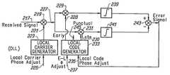
- a delay lock loop (DLL) correlatorthat is typically used in GPS receivers is shown in FIG. 4.
- a received signal 217may be radio frequency signal acquired by the antenna 203 , after some amplification, but generally is an intermediate frequency signal in a frequency range much lower than that received by the antenna 203 .
- a separate such DLL correlatoris provided for each satellite signal that is received by the receiver antenna in a single composite signal.
- One DLL correlatorthen processes that portion of the incoming signal that emanates from a particular satellite.
- the signal processing illustrated in FIG. 4is generally done in the digital domain, an analog-to-converter being employed to digitize the incoming intermediate frequency signal. That signal is digitized by a very high frequency sampling clock.
- the received signal 217in whatever form, is mixed in a mixer 219 with a signal 221 that is a replica of the carrier of the received signal 217 .
- This local carrieris generated by an appropriate circuit 223 , the phase of the local carrier signal 221 being adjusted by an input control signal 225 .
- a loop circuit to lock the carrier generator 223 onto that of the received signalis not shown in FIG. 4 since it can be of a typical design.
- the processing of a signal 227 at an output of the mixer 219is shown in more detail since it is in this processing where the present invention primarily lies.
- the signal 227is the received signal but with its carrier now removed. It is supplied to two mixers 229 and 231 which receive replicas 228 and 230 of a PRN code carried by the received signal.
- replicasare, respectively, “early” and “late” in relative phase with respect to a “punctual” replica 245 .
- These replicascome from a local code generator 233 within the receiver. In at least the case of the C/A code in the GPS system, the code carried by the received signal is well known and can be generated within the receivers. The relative phase of the locally generated code is adjusted by a phase control signal 235 . Further, in some receivers, another input 237 to the local code generator 233 allows adjustment of the delay between an early and late replicas of the locally generated code.
- Outputs of each of the mixers 229 and 231are applied to appropriate accumulators/integrators 239 and 241 , respectively.
- the outputs of the accumulators 239 and 241are arithmetically combined in another mixture 243 , whose output is an error signal that is applied to the input 235 of the local code generator 233 to adjust its phase.
- What the loop of FIG. 4 is designed to dois to lock the local code generator 233 in phase with the code carried by the received signal 217 .
- FIG. 5Bshows the characteristic output of the accumulator 239 from a comparison with the local early code
- the curve of FIG. 5Cthe output function of the accumulator 241 from a comparison with the local late code.
- the early and late locally generated PRN codesare separated by one chip. That is, the late code 230 is delayed behind the early signal 228 one PRN chip. This fixed delay is designated herein as “d” and is shown in FIG. 5 B.
- the early code functionoccurs one half a chip in advance of the punctual version, and the late code occurs one half a chip after the punctual version. It is often convenient to reference the early and late correlator outputs, such as shown in FIGS. 5B and 5C, to a central, in-phase line 247 .
- FIG. 5Dshows the error signal 235 , resulting from subtracting the correlator function of FIG. 5C from that of FIG. 5 B.
- the resultis a zero error signal at the in-phase point 247 when the local code generator 233 is properly locked onto the PRN code that is part of the received signal 217 .
- the error signalwill be driven positive or negative along the curve of FIG. 5 D.
- Such an error signaldrives the phase of the local code generator 233 in a direction to minimize the error signal, thus keeping the local generator 233 locked onto the incoming signal.
- the DLL correlator of FIG. 4is influenced by both. This is illustrated in FIG. 5 D. If only the line-of-sight signal 213 existed, the circuit of FIG. 4 would cause it to be aligned with the central zero phase reference line 247 . However, because of the multipath signal 215 being received, the local code generator 233 “locks” on a fictitious signal having a phase somewhere around them, as shown in FIG. 5 D. That is, the circuit of FIG. 4 is locking on to an incoming code phase that lies somewhere between that of the line-of-sight and multipath signals.
- the magnitude of the multipath signalmay be low with respect to that of the line-of-sight signal, because of attenuation from reflections of the multipath signal, its effect can be significant because of the steep curve of FIG. 5 D. It is a combination of the multipath signal magnitude and the value of the curve at the point of the arrow 215 , that determines the level of effect of the multipath signal on this phase lock operation.
- the line-of-sight signal vector 213will operate around the in-phase point 241 from that of the multipath signal vector 215 .
- the output of the early accumulator 239 in this caseis shown in FIG. 6 A.
- an output of the late accumulator 241 of FIG. 4is shown in FIG. 6 B.
- the error signal output of the adder-subtractor 243is shown in FIG. 6 C. It will be noticed that since the amplitude of the error signal function is considerably reduced, the multipath signal 215 has a significantly reduced effect. As can be seen from FIG.
- the magnitude of the error signal curve at the relative phase of the multipath signal vector 215is much less than in the example of FIG. 5 B.
- the resultis that, in a steady state phase lock state shown in FIG. 6C, the line-of-sight signal vector 213 is positioned much closer to a desired phase locked position 247 than is the line-of-sight signal.
- the DLL correlator of FIG. 4operating with an early-late local PRN code phase difference of one tenth of one chip, the DLL still has not locked on the line of sight signal.
- An erroris reduced in FIG. 6C from FIG. 5 D but is not eliminated.
- the multipath signalhas an effect in creating this error and thus reducing the accuracy by which a GPS receiver may achieve.
- the effect of multipath signalsis eliminated under certain circumstances and further reduced under other circumstances, by forming a DLL correlator of the type shown in FIG. 7 wherein two early-late correlations are arithmetically combined. Referring to FIG.
- an output 227 of the carrier mixer 219is applied to two correlators connected in parallel.
- a first correlatorincludes mixers 251 and 253 , the outputs of which are applied to an adder-subtractor 255 . An output of the latter mixer is then applied to an accumulator/integrator 257 .
- the second correlatorincludes mixers 259 and 261 , the outputs of which are applied to an adder-subtractor 263 . An output of that adder-subtractor is applied to and accumulator/integrator 265 .
- the mixer 251 of the first correlatorreceives an early code replica 267 from a local code generator (not shown in FIG. 7 ). Similarly, the mixer 253 receives a late code replica 269 . The result is an output 271 of the accumulator having a form shown in FIG. 9 A.
- the delay between the early and late replicas 267 and 269 , respectively,is designated to be d. This is the same as specifying the early signal 267 to be d/2 ahead of the central reference phase 279 (FIG. 9) and the late local code 269 being d/2 behind that reference t. It will be recognized that the output 271 shown in FIG. 9A is similar in shape to that of FIG. 6 C.
- the second correlatorreceives in lines 273 and 275 a locally generated code having a difference between the early and late locally generated codes that is 2d apart.
- An output 277 of the accumulator 265is illustrated in FIG. 9 B.
- the curve of FIG. 9Balso generally has the same shape as that of FIG. 6C but is different than that of FIG. 9A in having a longer slope central portion. This also results in the magnitude in the flat portions of the curve being higher than that of the curve of FIG. 9 A.
- a switch 291(FIG. 7) is provided to disconnect the second correlator from the circuit during initial signal acquisition.
- the correlator characteristic output of FIG. 9Bis non-exist but rather that of FIG. 9 A.
- the multipath signalhas some influence during this initial signal acquisition period but it is the purpose of the technique to bring the line-of-sight signal 213 within the operating range 281 . Once this occurs, the switch 291 is closed. This then eliminates the influence of the multipath signal.
- the DLL correlatorbrings the line-of-sight signal 213 exactly in coincidence with the in phase position 279 .
- the early-late of the second correlator whose output is illustrated in FIG. 9Bis twice that of a first correlator whose output is shown in FIG. 9 A. This results in each of the zero error signal regions 287 and 289 being 0.8 chip in duration, 80% of a possible relative phase difference is between the locally generated code and the PRN code that is part of the signal being received.
- the specific early-late phase differences that are chosen for the two correlatorsmay be within a wide range, so long as they are different, depending upon a particular application and what is desired to be achieved. It is generally preferable, however, that one of the two correlators of FIG. 7 have an early PRN code that is one 1/2K earlier than the in-phase locked position t, and its late PRN code 1/2K after t. Similarly, the second correlator has an early PRN code N/2K ahead of t, and a late PRN code N/2K after t.
- the scaling factor of the element 278 of FIG. 7remains at 1/2. If some other relationship between the two correlators is maintained, that scaling factor will generally need to be something different so that extended zero error signal regions 287 and 289 result when the accumulator output of FIG. 9C is subtracted from that of FIG. 9 A.
- FIG. 8shows a modification of FIG. 7 wherein four accumulators are used, instead of the two accumulators 257 and 265 of FIG. 7 .
- the purpose of FIG. 8is to show that the same result is obtained if the outputs of each of the individual mixers 251 , 253 , 259 and 261 are accumulated prior to any combination of any of those outputs.
- An adder-subtractor 293then receives outputs of the four accumulators, two of which now need to be scaled and switched rather than the single output 277 of FIG. 7 .
- FIG. 10An alternative to the use of early-late correlators, but which gives the same beneficial results, is illustrated in FIG. 10.
- a received signal 301is applied to a mixer 303 which also receives a replica 305 of the carrier contained in the signal 301 .
- a signal 307having a local carrier removed, is mixed in a mixer 339 with a gating sequence 341 from a local gating signal generator 343 .
- the mixed signal output of the mixer 339is applied to an accumulator/integrator 345 whose output 347 is the error signal that is used to adjust the phase of the output of the local gating signal generator 343 to minimize the error signal.
- FIG. 11Aillustrates PRN code that is modulated onto a carrier as part of the received signal 301 .
- the codeis a binary one, either being a plus one in level or a negative one in level.
- One of these levelsis chosen to represent a binary bit one, and the other a binary bit zero. Transitions between these levels occur at one chip intervals.
- the codedoes not transition between levels every chip, however, but rather its information is contained in the pseudo-random manner in which it stays for one or more chips at one value and then switches to another value for one or more chips, and then back again, and so on.
- FIG. 11Bshows one gating sequence 341 that may be utilized, it having a positive one value at each positive going transition of the incoming code of FIG. 11 A, and a negative one value at each negative going transition of the incoming code.
- the gating sequence 341is zero (FIG. 11B) when there is no transition where such a transition is possible.
- the transition of the gating sequence of FIG. 11Bcoincides with a middle of each chip of the incoming code.
- the result of using the gating sequence of FIG. 11Bis an error signal 347 which has essentially the same function as that shown in FIG. 5 D. That is, the DLL correlator of FIG. 10, when its gating sequence 341 is that of FIG. 11B, provides essentially the same result as the DLL correlator of FIG. 4 with its locally generated early-late PRN codes separated by one chip.
- FIG. 11Cshows a gating sequence 341 which gives an error signal 347 that is essentially the same as that shown in FIG. 6 C.
- a pulsehaving a duration of 0.1 chip.
- the polarity of the pulseis positive during a positive transition of the incoming code and negative during a negative transition of the incoming code.
- the width of the pulsecan be something other than 0.1 chip, which will then give an error signal function that is something different than that shown in FIG. 6 C.
- FIG. 11Dshows a local gating sequence according to one aspect of the present invention.
- Use of this form of the gating sequence 341gives an error signal 347 having essentially the same function as that shown in FIG. 9 D.
- the gating sequenceincludes, coincident with the occurrence of each transition of the incoming code of FIG. 11A, a pulse that has both positive and negative values.
- the gating sequence 341is a zero value in between these pulse functions. These pulse functions are considerably less than one chip in duration. Each pulse function has equal positive and negative areas.
- phase lockis achieved, a central portion of the pulse function of FIG. 11D is aligned with the transition of the incoming code of FIG. 11 A.
- the polarity of the central portion of the pulse function of FIG. 11Dis of one polarity, and if the incoming code transition is negative going, that pulse function central portion has an opposite polarity.
- FIG. 11Dit is shown that the central portion at a time 349 coincident with a positive going edge of the incoming code of FIG. 11A is positive, and that the pulse function central portion at a time 351 coincident with a negative going edge of the incoming code of FIG. 11A is negative, but these may be reversed.
- a single pulse function occurring about the incoming code transition 349can be viewed as having four distinct adjacent components.
- a central portion of the pulse functionhave areas 353 and 355 that are equal in area to each other on opposite sides of the transition line 349 when the error signal of the correlator of FIG. 10 is minimized.
- Areas 357 and 359have an opposite polarity to areas 353 and 355 and occur, respectively, ahead of and behind the pulse function areas 353 and 355 .
- the areas 353 and 357are caused to equal each other.
- the areas 355 and 359are caused to equal each other.
- the areas 353 and 355have a width of 0.1 chip with a plus 1 magnitude while each of the areas 357 and 359 has a width of one half that or 0.05 chip, with a minus one magnitude.
- curvesare given to illustrate the relative tracking error boundaries for various multipath signals having different values of delay from the line of sight signal desired to be locked onto.
- the outer-curves 361 and 363show the results of operating the DLL correlator of FIG. 4 in a manner described with respect to the curves of FIG. 5 .
- the dashed lines 365 and 367illustrate operation of the DLL correlator of FIG. 4 in accordance with the curves of FIG. 6, as described previously. It can be seen that the tracking error is considerably reduced but still is significant.
- a curve 369 of FIG. 13shows how the error is considerably reduced when one of the DLL correlators of FIGS. 7 or 8 , as explained with respect to the curves of FIG. 9, is utilized.
- FIG. 13shows in nanoseconds (ns) the envelope of zero tracking error for the three DLL correlators versus the delay ⁇ in ns, for a ratio ⁇ of the magnitude of the multipath signal to that of the line-of-sight signal is 0.5 with ⁇ varying between ⁇ and + ⁇ . It is obvious that for ⁇ between 0 and 10 ns, the zero tracking error is roughly identical for the three correlators, and for ⁇ around 100 ns the advantage is clearly in favor of the 0.1 chip edge DLL.
- the edge DLL correlator used on C/A codeis equivalent to a DLL correlator used on P code, and has the same beneficial multipath mitigation properties.
- GPSGlobal Positioning System
- GLONASSCommon Independent States' GLObal NAvigation Satellite System
- PRN sequenceany ranging system using a PRN sequence.
- This embodimentis described with one bit quantization; this choice, made for the sake of the simplicity of the description, does not preclude any constraint on the quantization.
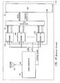
- the receiver 10includes an antenna 11 , a downconverter 12 , multiple channels 13 a to 13 n, an input/output interface 14 , and a digital processor 15 .
- the antenna 11receives a composite signal RF, composed of signals from all satellites in the system that are directly in the line of sight of the antenna.
- the composite signal RFis fed to the down-converter 12 to provide a quantized and sampled intermediate frequency signal IFW, a system sampling clock Ft and a SYSTEM CLOCK.
- the signal IFWis a word of 4 bits, each representing one of four IF consecutive samples at a FS sampling rate.
- the processing clock Ftis a division by 4 of the Fs signal.
- the system clockis a further division of Ft signal, interrupting the processor at a rate of approximately 1 per millisecond and triggering the channel processing.
- the RF signalis first prefiltered by the RF filter 120 , amplified by 121 , and mixed with the Local Oscillator (LO) by the mixer 122 , filtered and amplified again in IF by 123 and 124 , and finally quantized in one bit by the hard limiter 125 .
- the filter 123is in fact used as a pre-correlation filter with a two-sided bandwidth of 20.46 Mhz.
- the instantaneous hard limiter outputis sampled at a rate of Fs, and shifted in the 4-stage shift register 126.
- the sampling rate Fsis chosen to satisfy the Nyquist rate requirement, related to the pre-correlation filter bandwidth. Every Ft clock transition (i.e. 4 Fs clocks), the full contents of the shift register is transferred into a parallel register 127 .
- the 4 bit word IFWis then transferred to the channel circuits at a Ft rate for satellite individual tracking.
- the clock reference circuitry of the down converterincludes a phase lock loop (PLL) which is composed itself of the voltage controlled oscillator (VCO) 131 , a frequency divider 132 , a phase comparator 129 , which compares the phase with a stable reference oscillator 128 , and, finally, a low frequency loop filter 130 .
- the VCO outputis used as local oscillator for the RF section.
- the frequency of the VCO 131is divided in several steps, a first time by a divider 133 to get the sampling frequency Fs, a second time by a divider 134 to get the processing clock Ft, and a third time by a divider 135 to get the SYSTEM CLOCK.
- the sampled and quantized intermediate frequency signal IFWis simultaneously fed to each of the several signal processing channels 13 a to 13 n.
- a separate channel 13is devoted to every visible satellite; the assignment to a given satellite is made by configuring the pseudo-random noise (PRN) generator through the PRN GENERATOR COMMANDS.
- PRNpseudo-random noise
- the structure of a channel 13typical of each of the channels 13 a- 13 n, is given in FIG. 16 . Every satellite signal is simultaneously tracked in carrier phase by a carrier Phase Lock Loop(PLL) and in code phase by a Delay Lock Loop (DLL). All channel processing is made in a fully synchronous manner at a processing clock Ft. IFW samples are processed 4 by 4, and all carrier and code generation is made at Ft rate by groups of 4 as well.
- PLLPhase Lock Loop
- DLLDelay Lock Loop
- Both the PLL and the DLLare implemented partly in the channel 13 , and partly in the processor 15 .
- the linkis made by the I/O interface 14 .
- the loop comparators and the loop actuatorsare located in each channel, whereas the filter implementation and the loop management are handled by the processor 15 .
- the loopsare updated when the processor is interrupted by the SYSTEM CLOCK signal and the MEAS READY signal is set for that channel, informing the processor that a measurement cycle has just finished. All measurement cycles are chosen at a period bigger than that of the SYSTEM CLOCK, in order not to miss any measurement.
- the cycle periodis set by the processor at every channel initialization, through the PRN GENERATOR COMMAND.
- the carrier PLLuses the measurements I and Q of an in-phase correlator 130 a, and a quadrature phase correlator 130 b. In a tracking mode, the PLL drives the information Q to zero while checking for the presence of the signal locking on I. Both correlators are using the. same “punctual” pseudo-random code (PRN) for the correlation, but use different carrier signals COS and SIN.
- PRNpseudo-random code
- the processed informationis used to control the CARRIER FREQUENCY COMMAND of a carrier numerically controlled oscillator (NCO) 132 .
- the carrier NCO 132is described in detail in FIG. 17 .
- the instantaneous carrier phase imageis kept in a carrier phase register 1325 , where the total range represents 2 ⁇ of carrier phase.
- the current CARRIER FREQUENCY COMMANDis kept in a frequency command register 1323 . At every Ft transition, this value is added to the current carrier phase register contents by the adder 1321 c; thus, the carrier phase is incremented one full cycle every time the carrier phase register 1325 cycles back to zero.
- the instantaneous carrier phasecan be obtained at any SYSTEM CLOCK transition or at every Ft very straightforwardly; the carrier phase register 1325 is reset synchronously with the SYSTEM CLOCK at the initial CHANNEL RESET command, ensuring a known initial phase. Every processor command loaded into a buffer 1324 is transferred into the frequency command register 1323 and effective at the next SYSTEM CLOCK transition; as the SYSTEM CLOCK period is an exact number of Ft periods and knowing the loaded command word, the exact value in the carrier phase register is obtained at the next SYSTEM CLOCK transition or at any Ft clock transition in between by direct computation.
- the one bit reference carrier cosine value C 0is obtained by “exclusively ORing” the most significant bit (MSB) and the second most significant bit of the carrier phase register contents.
- the one bit reference carrier sine valueis obtained using the MSB of carrier phase register contents; this is actually done in the phase/quadrature signal generator 1320 c.
- the carrier referencesare generated synchronously with the exact sampling times for the 3 other samples as well.
- the reference signalis chosen to be the third of the sequence of 4.
- the carrier phase 1325is physically incremented by the frequency command value 1323 every Ft. It is equivalent to say that the instantaneous carrier phase is virtually incremented by a fourth of this value every Fs (i.e. four times per Ft period).
- the reference carrier phase synchronous with the fourth sample (most recent one)is obtained by adding frequency command divided by four (divider 1322 c ) to the current carrier phase 1325 ; the carrier cosine (sine) value C +1 (S +1 ), delayed of one sampling period, is obtained from it with the phase quadrature signal Generator 1320 d using the same algorithm as for C 0 and S 0 .
- C ⁇ 2 , S ⁇ 2are obtained by subtracting frequency command value divided by 2 using 1322 a from the current carrier phase 1325 . This substraction is performed by using the adder 1321 a. The cosine and sine values are finally obtained through 1320 a.
- C ⁇ 1 ,S ⁇ 1are obtained by subtracting the frequency command value divided by 4 using 1322 b from the current carrier phase 1325 . This substraction is made using the adder 1321 b. The cosine and sine values are finally obtained through 1320 b.
- the full NCO outputis a “cosine” word COS and a “sine” word SIN of 4 bits each, each bit being the sampled carrier reference value one sample apart.
- the “punctual” in-phase ( 130 a ) and quadrature-phase ( 130 b ) correlators for the PLLare described in FIG. 19 . Given the close similarity, the following correlator description deals with only the in-phase case.
- the intermediate frequency word IFW composed of 4 samplesis “exclusive ORed” with the 4 bit cosine carrier reference COS in the structure 1301 a to 1301 d. All samples are added in the adder 1302 ; the result is comprised between ⁇ 4 and +4 (the “0”values are processed as “ ⁇ 1”by the adder 1302 ). The result is then multiplied by the value of reference PRN sequence synchronous with the most recent sample (multiplier 1303 ). The resulting value is then algebraically added at a Ft rate to the current contents of the accumulator 1305 . At every CYCLE transition the accumulator value is transferred to the buffer, the accumulator is reset, and finally a new measurement period is initiated. The processor is then able to read the measurement values to close the loops.
- the DLLhas 2 configurations, acquisition mode or tracking mode, depending on the channel locking phase.
- the tracking modepreferably uses an “edge DLL” correlator, while the acquisition mode uses a 0.1 chip delay DLL.
- the selection between 2 modesis made through the signal DLL SELECT.
- Other specific combinations of tracking and acquisition mode correlatorsmay also be employed.
- the delay lock loop (DLL) processingis timed at a Ft rate similarly to the PLL, and the measurement update rate is CYCLE as well.
- the DLLuses dI and dQ information coming from an in-phase DLL correlator 131 a for dI, and a quadrature phase DLL correlator 131 b for dQ.
- the DLLdrives the dQ value to zero when in tracking mode.
- the dQis used in conjunction with dI when in acquisition mode.
- the processed informationis used to control the PRN GENERATOR COMMANDS of the PRN Code Generator 133 .
- each time intervalhas an exact duration of 1/Fs or the IF sampling period.
- every time intervalcontains one and only one IF sample at a Fs rate.
- the relative position of the samples in the intervalis unknown and depends on the relative phase between code generator and sampling clock.
- the full formula expressing the DLL responseis given below.
- S ⁇ 2 , S ⁇ 1 , S +1 , S +2is a sequence of four consecutive IF samples with the code transition between S ⁇ 1 and S +1
- dPRNmay be defined as:
- dPRN1 ⁇ 2 ⁇ ( PRN +1 ⁇ PRN ⁇ 1 )
- dPRNcan be thought as the derivative of the PRN sequence.
- DLL i( ⁇ S ⁇ 2 +S ⁇ 1 +S +1 ⁇ S +2 ) ⁇ dPRN
- This summationperforms a low pass frequency filtering function of the measurements dI and dQ.
- Elementay DLL P1 P0falls operation in tracking Elementay DLL operation value value between mode in acquisition mode 0 0 S 3A and S 4A ( ⁇ S 2A + S 3A + S 4A ⁇ S 1 ) ⁇ dPRN (+S 2A + S 3A + S 4A + S 1 ) ⁇ dPRN 0 1 S 4A and S 1 ( ⁇ S 3A + S 4A + S 1 ⁇ S 2 ) ⁇ dPRN (+S 3A + S 4A + S 1 + S 2 ) ⁇ dPRN 1 0 S 1 and S 2 ( ⁇ S 4A + S 1 + S 2 ⁇ S 3 ) ⁇ dPRN (+S 4A + S 1 + S 2 + S 3 ) ⁇ dPRN 1 1 S 2 and S 3 ( ⁇ S 1 + S 2 + S 3 ⁇ S 4 ) ⁇ dPRN (S 1 + S 2 + S 3 + S 4 ) ⁇ dPRN (S 1 + S 2 + S 3 + S 4 ) ⁇ dPRN (S 1 + S 2 + S 3
- the current value between +4 and ⁇ 4is algebraically added to the accumulator 1316 by the adder 1315 during the same Ft transition. Every transition on CYCLE transfers the accumulator value to the buffer 1317 , resets the accumulator, and finally initiates a new measurement period.
- the circuitryis identical up to the adder 1313 , except that the first and last sample coming out from the multiplexor 1311 a and 1311 d are not inverted.
- the dPRN signalis defined the same way than previously, but its size is expanded to reach 0.1 code chip duration, centered on the code transition.
- the Generatoris in fact composed of a code numerically controlled oscillator (NCO), which delivers a chip frequency clock Fc whose frequency is in direct control of the processor through the CODE FREQUENCY COMMAND; in turn, Fc clocks the PRN code generator 1334 per se.
- NCOcode numerically controlled oscillator
- the Code NCO descriptionsimilarly to the carrier NCO, it is embodied by a code phase register 1335 , whose full range represents 2 II of the code phase.
- the word into code frequency command register 1336is added (modulo the range of code phase register) to the contents of the code phase register by the adder 1331 d.
- the carry signal coming from the adderis used as chip frequency Fc.
- the CODE FREQUENCY COMMAND word present in the code frequency command registeris loaded at every SYSTEM CLOCK transition from the buffer 1337 .
- the bufferis itself loaded from the processor at any time.
- Another important function of the code NCOis to deliver the signals P 0 and P 1 , whose function was described earlier.
- the P 0 caseis different depending on the P 1 value. If P 1 is zero (CPR ⁇ 2 ⁇ ), CFR, divided by four (by divider 1332 a ), is multiplied by ⁇ 1 in the multiplier 1331 b; if P 1 is one (CPR ⁇ 2 ⁇ ), CFR/4 is multiplied by +1. Then 1331 a adds RES 1 to the multiplication result; the carry of the adder 1331 a is taken as P 0 . The final result is in agreement with Table 2.
- the PRN code generator 1334is clocked by the chip frequency Fc. It is configured for a particular satellite sequence by the command GENERATOR PRESET. It outputs an epoch signal, synchronous with a particular instant in the PRN sequence, which is taken as reference in the PRN ranging sequence. The data bits superimposed on the PRN sequence have their transition perfectly synchronous with this epoch signal.
- the EPOCH signalclocks the cycle counter 1333 , which is reset at the initialization of the channel by the SYNC RESET, and counts an integer number of epochs (preset at the preset sequence) before to generate a transition on CYCLE, which stops the current measurement cycle on all correlators and informs the processor by the signal MEAS READY. Every channel has its own cycle counter, synchronized on its own data transitions. After a synchronizing phase on the data transitions, it is possible to slow down the measurement periods up to 20 ms, no data transitions occurring during this period.
- edge DLL correlator used on C/A codewith a precorrelation bandwidth prefiltering (typically 20.46 Mhz double sided) improves the multipath error.
- a PRN code transition detectoris built X-ORing the current code output and the previous one latched in the latch 1339 .
- the signal dPRNis generated by 1338 according to the description in the DLL principle explanation.
- the direct received signalis given by:
- Ais the amplitude of the received signal
- PRN(t)is the pseudo-random sequence
- ⁇ 0is the carrier frequency pulsation
- ⁇is the carrier phase offset
- the multipath signalis given by:
- ⁇is the amplitude ratio between direct and multipath signal
- ⁇is the propagation delay between direct and multipath signal
- ⁇is the additional phase rotation between direct and multipath signal.
- the main effect of the presence of a multipath signalis to shift the zero crossing of the DLL response from the “zero multipath” reference differently for each of the three discriminators.
- the DLL driving the DLL correlator output to zero in averagethe difference between zero crossings will be seen directly as an error in the measured code phase.
- the position computationwill be erroneous.
- FIGS. 21B, 21 C and 21 Dgive other examples of what the gating signal generator 343 can provide in line 341 .
- the result in terms of the error signal characteristic of FIG. 9Dis substantially the same, but the different gating sequences of FIGS. 21B-D cause the height and duration of the non-zero portions of the FIG. 9D curve to change somewhat.
- the fundamental advantageis retained, however, of providing extended intervals where the error signal is zero.
- a carefully controlled gating signaloccurs at each of transitions 365 , 367 , etc., of the incoming code (FIG. 21 A).
- negative portions 369 and 371 of the signalhave a magnitude less than 1, while corresponding positive portions 373 and 375 have a magnitude of 1.
- the lower magnitude negative portions of the signalare given longer durations, however, so that the areas of the pulse portions 369 and 373 are equal, as are the areas 371 and 375 .
- a positive area 377(magnitude less than 1) is much smaller than a negative area 379 (magnitude more than 1), while a positive area 381 is much smaller than a negative going area 383 .
- This gating signaldiffers from the others shown herein by aligning with the code signal edge 365 (when a minimum error condition exists) a transition between negative and positive going portions of the signal.
- Each of the signals of FIGS. 11D, 12 , 21 B and 21 Cis symmetrical about the code edge. The signals are positioned with their middle aligned with the code edge.
- the gating signalis non-symmetrical about the incoming code edge.
- the positive and negative going pulse portionshave equal areas on each side of the code edge. That is, areas 385 and 387 , on one side of the code edge 365 , are substantially equal, while the areas 389 and 391 on the other side of the code edge 365 are also substantially equal.
- compound gating pulse shapesAlthough several specific examples of compound gating pulse shapes have been given, there are numerous other shapes, with various relative magnitudes, that can be employed instead.
- the total negative and positive going areas of any such compound gating pulseis made to be substantially equal. This property causes the multipath signal to be substantially eliminated so long as its delay from the line of sight signal is sufficient.
Landscapes
- Engineering & Computer Science (AREA)
- Radar, Positioning & Navigation (AREA)
- Remote Sensing (AREA)
- Computer Networks & Wireless Communication (AREA)
- Physics & Mathematics (AREA)
- General Physics & Mathematics (AREA)
- Signal Processing (AREA)
- Position Fixing By Use Of Radio Waves (AREA)
Abstract
Description

| TABLE 1 | ||||
| code | ||||
| transition | Elementay DLL | |||
| P1 | P0 | falls | operation in tracking | Elementay DLL operation |
| value | value | between | mode | in |
| 0 | 0 | S3Aand S4A | (−S2A+ S3A+ S4A− S1)⊕dPRN | (+S2A+ S3A+ S4A+ S1)⊕ |
| 0 | 1 | S4Aand S1 | (−S3A+ S4A+ S1− S2)⊕dPRN | (+S3A+ S4A+ S1+ S2)⊕ |
| 1 | 0 | S1and S2 | (−S4A+ S1+ S2− S3)⊕dPRN | (+S4A+ S1+ S2+ S3)⊕ |
| 1 | 1 | S2and S3 | (−S1+ S2+ S3− S4)⊕dPRN | (S1+ S2+ S3+ S4)⊕dPRN |
| TABLE 2 | ||||||
| 0 < CPR ≦ Δ | Δ < CPR ≦ 2Δ | 2Δ < CPR ≦ R − 2Δ | R − 2Δ < CPR ≦ R − Δ | R − Δ < CPR ≦ | ||
| P1 |
| 0 | 0 | 1 | 1 | 1 | |
| 1 | 0 | 0 | 1 | 0 | |
Claims (4)
Priority Applications (1)
| Application Number | Priority Date | Filing Date | Title |
|---|---|---|---|
| US09/577,023US6463091B1 (en) | 1995-08-09 | 2000-05-23 | Spread spectrum receiver using a pseudo-random noise code for ranging applications in a way that reduces errors when a multipath signal is present |
Applications Claiming Priority (3)
| Application Number | Priority Date | Filing Date | Title |
|---|---|---|---|
| US08/512,822US5953367A (en) | 1995-08-09 | 1995-08-09 | Spread spectrum receiver using a pseudo-random noise code for ranging applications in a way that reduces errors when a multipath signal is present |
| US29057699A | 1999-04-13 | 1999-04-13 | |
| US09/577,023US6463091B1 (en) | 1995-08-09 | 2000-05-23 | Spread spectrum receiver using a pseudo-random noise code for ranging applications in a way that reduces errors when a multipath signal is present |
Related Parent Applications (1)
| Application Number | Title | Priority Date | Filing Date |
|---|---|---|---|
| US29057699AContinuation | 1995-08-09 | 1999-04-13 |
Publications (1)
| Publication Number | Publication Date |
|---|---|
| US6463091B1true US6463091B1 (en) | 2002-10-08 |
Family
ID=24040725
Family Applications (2)
| Application Number | Title | Priority Date | Filing Date |
|---|---|---|---|
| US08/512,822Expired - LifetimeUS5953367A (en) | 1995-08-09 | 1995-08-09 | Spread spectrum receiver using a pseudo-random noise code for ranging applications in a way that reduces errors when a multipath signal is present |
| US09/577,023Expired - LifetimeUS6463091B1 (en) | 1995-08-09 | 2000-05-23 | Spread spectrum receiver using a pseudo-random noise code for ranging applications in a way that reduces errors when a multipath signal is present |
Family Applications Before (1)
| Application Number | Title | Priority Date | Filing Date |
|---|---|---|---|
| US08/512,822Expired - LifetimeUS5953367A (en) | 1995-08-09 | 1995-08-09 | Spread spectrum receiver using a pseudo-random noise code for ranging applications in a way that reduces errors when a multipath signal is present |
Country Status (1)
| Country | Link |
|---|---|
| US (2) | US5953367A (en) |
Cited By (54)
| Publication number | Priority date | Publication date | Assignee | Title |
|---|---|---|---|---|
| US20030190889A1 (en)* | 2002-04-03 | 2003-10-09 | The Aerospace Corporation | Mobile surface terminal communication system |
| US6738412B1 (en)* | 1999-04-21 | 2004-05-18 | Matsushita Electric Industrial Co., Ltd. | Mobile communications device, communications system, and communications method |
| US6744404B1 (en)* | 2003-07-09 | 2004-06-01 | Csi Wireless Inc. | Unbiased code phase estimator for mitigating multipath in GPS |
| US20040151272A1 (en)* | 2003-01-31 | 2004-08-05 | Kenney Thomas J. | Delay lock loop circuit, and associated method, for a radio receiver |
| US20040166810A1 (en)* | 2002-09-10 | 2004-08-26 | Young-Kwon Cho | Apparatus and method for tracking a phase of a pseudo-random noise (PN) sequence of a pilot signal in a mobile terminal |
| US20050234667A1 (en)* | 2004-04-15 | 2005-10-20 | Howard Hilton | System and method for processing a periodic or cyclostationary signal |
| US20060140254A1 (en)* | 2004-12-29 | 2006-06-29 | Nokia Corporation | Multi-path detection method for CDMA receivers |
| US20060171491A1 (en)* | 2005-01-28 | 2006-08-03 | Jukka Tapaninen | Diversity-mode delay lock loop circuit and associated method for a radio receiver |
| WO2006128298A1 (en)* | 2005-06-03 | 2006-12-07 | Novatel, Inc. | Apparatus for and method of improving position and time estimation of radio location devices using calibrated pulse shapes |
| US20080292022A1 (en)* | 2007-05-21 | 2008-11-27 | Gregory Blum | Radio Receiver Including a Delay-Locked Loop (DLL) for Phase Adjustment |
| US20090213912A1 (en)* | 2007-11-27 | 2009-08-27 | Nemerix Sa | Multipath mitigation gnss receiver |
| US20100027602A1 (en)* | 2008-07-31 | 2010-02-04 | United States Of America As Represented By The Administrator Of The National Aeronautics And Spac | Time delay and distance measurement |
| US20100029237A1 (en)* | 2008-08-04 | 2010-02-04 | Nec Electronics Corporation | Radio receiving apparatus and radio receiving method |
| US20100104046A1 (en)* | 2006-08-10 | 2010-04-29 | Hodgart Matthew Stephen | Receiver of binary offset carrier (boc) modulated signals |
| US20100111140A1 (en)* | 2007-04-02 | 2010-05-06 | Zhengdi Qin | Methods, Apparatuses and Computer Program Products for Code Correlation of Multi-Path Spread Spectrum Signals |
| US20100128342A1 (en)* | 2008-11-26 | 2010-05-27 | Abramovitch Daniel Y | Coherent Demodulation with Reduced Latency Adapted for use in Scanning Probe Microscopes |
| US20100135364A1 (en)* | 2007-01-24 | 2010-06-03 | The University Of Surrey | Receiver of multiplexed binary offset carrier (mboc) modulated signals |
| US7764226B1 (en) | 2006-04-07 | 2010-07-27 | Topcon Gps, Llc | Universal digital channel for receiving signals of global navigation satellite systems |
| US7835832B2 (en) | 2007-01-05 | 2010-11-16 | Hemisphere Gps Llc | Vehicle control system |
| US7885745B2 (en) | 2002-12-11 | 2011-02-08 | Hemisphere Gps Llc | GNSS control system and method |
| US7908080B2 (en) | 2004-12-31 | 2011-03-15 | Google Inc. | Transportation routing |
| US7948769B2 (en) | 2007-09-27 | 2011-05-24 | Hemisphere Gps Llc | Tightly-coupled PCB GNSS circuit and manufacturing method |
| US8000381B2 (en) | 2007-02-27 | 2011-08-16 | Hemisphere Gps Llc | Unbiased code phase discriminator |
| US8018376B2 (en) | 2008-04-08 | 2011-09-13 | Hemisphere Gps Llc | GNSS-based mobile communication system and method |
| US20110241923A1 (en)* | 2010-03-30 | 2011-10-06 | Escort Manufacturing Corporation | Digital receiver techniques in radar detectors |
| US8085196B2 (en) | 2009-03-11 | 2011-12-27 | Hemisphere Gps Llc | Removing biases in dual frequency GNSS receivers using SBAS |
| US8140223B2 (en) | 2003-03-20 | 2012-03-20 | Hemisphere Gps Llc | Multiple-antenna GNSS control system and method |
| US8138970B2 (en) | 2003-03-20 | 2012-03-20 | Hemisphere Gps Llc | GNSS-based tracking of fixed or slow-moving structures |
| US8174437B2 (en) | 2009-07-29 | 2012-05-08 | Hemisphere Gps Llc | System and method for augmenting DGNSS with internally-generated differential correction |
| US8190337B2 (en) | 2003-03-20 | 2012-05-29 | Hemisphere GPS, LLC | Satellite based vehicle guidance control in straight and contour modes |
| US8217833B2 (en) | 2008-12-11 | 2012-07-10 | Hemisphere Gps Llc | GNSS superband ASIC with simultaneous multi-frequency down conversion |
| US8265826B2 (en) | 2003-03-20 | 2012-09-11 | Hemisphere GPS, LLC | Combined GNSS gyroscope control system and method |
| US8271194B2 (en) | 2004-03-19 | 2012-09-18 | Hemisphere Gps Llc | Method and system using GNSS phase measurements for relative positioning |
| US8311696B2 (en) | 2009-07-17 | 2012-11-13 | Hemisphere Gps Llc | Optical tracking vehicle control system and method |
| US8334804B2 (en) | 2009-09-04 | 2012-12-18 | Hemisphere Gps Llc | Multi-frequency GNSS receiver baseband DSP |
| US8386129B2 (en) | 2009-01-17 | 2013-02-26 | Hemipshere GPS, LLC | Raster-based contour swathing for guidance and variable-rate chemical application |
| US20130051434A1 (en)* | 2008-03-18 | 2013-02-28 | Argon St, Inc. | System and method for mitigating severe multipath interference for geolocation & navigation |
| US8401704B2 (en) | 2009-07-22 | 2013-03-19 | Hemisphere GPS, LLC | GNSS control system and method for irrigation and related applications |
| US8456356B2 (en) | 2007-10-08 | 2013-06-04 | Hemisphere Gnss Inc. | GNSS receiver and external storage device system and GNSS data processing method |
| US8548649B2 (en) | 2009-10-19 | 2013-10-01 | Agjunction Llc | GNSS optimized aircraft control system and method |
| US8583326B2 (en) | 2010-02-09 | 2013-11-12 | Agjunction Llc | GNSS contour guidance path selection |
| US8583315B2 (en) | 2004-03-19 | 2013-11-12 | Agjunction Llc | Multi-antenna GNSS control system and method |
| US8594879B2 (en) | 2003-03-20 | 2013-11-26 | Agjunction Llc | GNSS guidance and machine control |
| US8649930B2 (en) | 2009-09-17 | 2014-02-11 | Agjunction Llc | GNSS integrated multi-sensor control system and method |
| US8686900B2 (en) | 2003-03-20 | 2014-04-01 | Hemisphere GNSS, Inc. | Multi-antenna GNSS positioning method and system |
| US8908744B1 (en)* | 2010-02-10 | 2014-12-09 | Marvell International Ltd. | Discriminator system for timing error detection in presence and absence of multipath conditions |
| US9002566B2 (en) | 2008-02-10 | 2015-04-07 | AgJunction, LLC | Visual, GNSS and gyro autosteering control |
| US9178561B2 (en) | 2013-09-11 | 2015-11-03 | Marvell World Trade Ltd. | Method and apparatus for correlating signals received from a navigation satellite system |
| US9581700B2 (en) | 2012-12-12 | 2017-02-28 | Samsung Electronics Co., Ltd. | Method and apparatus tracking global navigation satellite system (GNSS) |
| US9880562B2 (en) | 2003-03-20 | 2018-01-30 | Agjunction Llc | GNSS and optical guidance and machine control |
| USRE47101E1 (en) | 2003-03-20 | 2018-10-30 | Agjunction Llc | Control for dispensing material from vehicle |
| USRE48527E1 (en) | 2007-01-05 | 2021-04-20 | Agjunction Llc | Optical tracking vehicle control system and method |
| US20230059120A1 (en)* | 2020-06-23 | 2023-02-23 | Massive Light, LLC | Large instantaneous bandwidth radio frequency front-end for wireless systems |
| US12313763B1 (en) | 2020-11-30 | 2025-05-27 | Nolimits Enterprises, Inc. | Programmable digital subchannel processor for radar detector |
Families Citing this family (24)
| Publication number | Priority date | Publication date | Assignee | Title |
|---|---|---|---|---|
| US6678311B2 (en) | 1996-05-28 | 2004-01-13 | Qualcomm Incorporated | High data CDMA wireless communication system using variable sized channel codes |
| JP2988398B2 (en)* | 1996-11-27 | 1999-12-13 | 日本電気株式会社 | Unique word differential detection system and demodulator |
| DE19712751A1 (en)* | 1997-03-26 | 1998-10-08 | Deutsch Zentr Luft & Raumfahrt | Receiver for signals provided by satellite navigation system |
| US6549559B2 (en)* | 1997-12-23 | 2003-04-15 | Koninklijke Philips Electronics N.V. | Apparatus and method for locking onto a psuedo-noise code in an IS-95 spread spectrum communications system |
| US6493378B1 (en)* | 1998-01-06 | 2002-12-10 | Topcon Gps Llc | Methods and apparatuses for reducing multipath errors in the demodulation of pseudo-random coded signals |
| US6442189B1 (en)* | 1998-01-14 | 2002-08-27 | Lg Electronics, Inc. | Binary code phase offset calculation method and a binary code phase synchronization method by using the phase offset |
| DE19832851C1 (en)* | 1998-07-21 | 2000-03-30 | Siemens Ag | Acquisition process and arrangement for carrying out the process |
| JP3092598B2 (en)* | 1998-09-08 | 2000-09-25 | 日本電気株式会社 | Mobile communication device and mobile communication method |
| AU3280299A (en)* | 1998-11-11 | 2000-05-29 | Samsung Electronics Co., Ltd. | Receiver for pseudo-noise signals from satellite radio-navigation systems |
| DE19953350A1 (en)* | 1999-11-05 | 2001-05-23 | Infineon Technologies Ag | Device for fine synchronization of code signals |
| US6687316B1 (en)* | 2000-01-25 | 2004-02-03 | Rockwell Collins, Inc. | High resolution correlator technique for spread spectrum ranging system code and carrier multipath mitigation |
| US6704650B1 (en)* | 2000-05-31 | 2004-03-09 | Skynetix, Llc | Technique for accurate distance and velocity calculations using the global positioning system (GPS) |
| US6970499B2 (en)* | 2001-05-30 | 2005-11-29 | Koninklijke Philips Electronics N.V. | Varying early-late spacing in a delay locked loop |
| EP1288672A1 (en)* | 2001-08-08 | 2003-03-05 | Septentrio N.V. | Method and apparatus for processing signals for ranging applications |
| US20030108133A1 (en)* | 2001-10-11 | 2003-06-12 | Richards James L. | Apparatus and method for increasing received signal-to-noise ratio in a transmit reference ultra-wideband system |
| KR100823129B1 (en)* | 2004-08-18 | 2008-04-21 | 삼성전자주식회사 | Tracking device and method of mobile communication system |
| KR100826376B1 (en)* | 2006-11-24 | 2008-05-02 | 삼성전기주식회사 | Correlation method and signal processing method using mapping of CDMA receiver |
| JP5440894B2 (en)* | 2007-10-03 | 2014-03-12 | 測位衛星技術株式会社 | Position information providing system and indoor transmitter |
| US8599068B2 (en)* | 2010-10-05 | 2013-12-03 | Sanjai Kohli | Systems and methods for mobile terminal location verification |
| EP2745141A1 (en)* | 2011-08-16 | 2014-06-25 | European Space Agency | A navigation system using spreading codes based on pseudo-random noise sequences |
| CN102508199A (en)* | 2011-11-12 | 2012-06-20 | 太原理工大学 | Positioning method based on radio phase discriminating technology |
| US20170261617A1 (en)* | 2015-09-23 | 2017-09-14 | Topcon Positioning Systems, Inc. | Method of reducing inter-channel biases in glonass gnss receivers |
| EP3483632A1 (en) | 2017-11-09 | 2019-05-15 | Septentrio N.V. | Method for correcting a pseudorange in a receiver for satellite navigation |
| EP3862789A1 (en)* | 2020-02-07 | 2021-08-11 | Rohde & Schwarz GmbH & Co. KG | Signal generation system as well as method of signal generation |
Citations (17)
| Publication number | Priority date | Publication date | Assignee | Title |
|---|---|---|---|---|
| US4754465A (en) | 1984-05-07 | 1988-06-28 | Trimble Navigation, Inc. | Global positioning system course acquisition code receiver |
| US4809005A (en) | 1982-03-01 | 1989-02-28 | Western Atlas International, Inc. | Multi-antenna gas receiver for seismic survey vessels |
| US4847862A (en) | 1988-04-07 | 1989-07-11 | Trimble Navigation, Ltd. | Global positioning system course acquisition code receiver |
| US4928106A (en) | 1988-07-14 | 1990-05-22 | Ashtech Telesis, Inc. | Global positioning system receiver with improved radio frequency and digital processing |
| US5101416A (en) | 1990-11-28 | 1992-03-31 | Novatel Comunications Ltd. | Multi-channel digital receiver for global positioning system |
| EP0552975A2 (en) | 1992-01-24 | 1993-07-28 | Novatel Communications Ltd. | A pseudorandom noise ranging receiver which compensates for multipath distortion by dynamically adjusting the time delay spacing between early and late correlators |
| US5347536A (en) | 1993-03-17 | 1994-09-13 | The United States Of America As Represented By The Administrator Of The National Aeronautics And Space Administration | Multipath noise reduction for spread spectrum signals |
| US5390207A (en) | 1990-11-28 | 1995-02-14 | Novatel Communications Ltd. | Pseudorandom noise ranging receiver which compensates for multipath distortion by dynamically adjusting the time delay spacing between early and late correlators |
| US5402450A (en) | 1992-01-22 | 1995-03-28 | Trimble Navigation | Signal timing synchronizer |
| US5402441A (en) | 1992-08-20 | 1995-03-28 | Japan Radio Co., Ltd. | Signal receiver for global positioning system |
| US5414729A (en) | 1992-01-24 | 1995-05-09 | Novatel Communications Ltd. | Pseudorandom noise ranging receiver which compensates for multipath distortion by making use of multiple correlator time delay spacing |
| US5436935A (en) | 1992-09-29 | 1995-07-25 | Ascom Tech Ag. | Process for synchronizing a receiver switching circuit to a received signal containing a pn-code-spread data signal |
| US5493588A (en) | 1992-01-22 | 1996-02-20 | Trimble Navigation Limited | Multipath compensation for code phase signals |
| US5517535A (en) | 1994-10-13 | 1996-05-14 | Westinghouse Electric Corp. | Numerically controlled oscillator with complex exponential outputs using recursion technique |
| US5537121A (en) | 1995-04-28 | 1996-07-16 | Trimble Navigation Limited | Carrier phase multipath reduction technique |
| WO1996037789A1 (en) | 1995-05-24 | 1996-11-28 | Leica Geosystems Inc. | Mitigation of multipath effects in global positioning system receivers |
| US5630208A (en)* | 1994-07-19 | 1997-05-13 | Trimble Navigation Limited | Adaptive multipath equalization |
- 1995
- 1995-08-09USUS08/512,822patent/US5953367A/ennot_activeExpired - Lifetime
- 2000
- 2000-05-23USUS09/577,023patent/US6463091B1/ennot_activeExpired - Lifetime
Patent Citations (18)
| Publication number | Priority date | Publication date | Assignee | Title |
|---|---|---|---|---|
| US4809005A (en) | 1982-03-01 | 1989-02-28 | Western Atlas International, Inc. | Multi-antenna gas receiver for seismic survey vessels |
| US4754465A (en) | 1984-05-07 | 1988-06-28 | Trimble Navigation, Inc. | Global positioning system course acquisition code receiver |
| US4847862A (en) | 1988-04-07 | 1989-07-11 | Trimble Navigation, Ltd. | Global positioning system course acquisition code receiver |
| US4928106A (en) | 1988-07-14 | 1990-05-22 | Ashtech Telesis, Inc. | Global positioning system receiver with improved radio frequency and digital processing |
| US5390207A (en) | 1990-11-28 | 1995-02-14 | Novatel Communications Ltd. | Pseudorandom noise ranging receiver which compensates for multipath distortion by dynamically adjusting the time delay spacing between early and late correlators |
| US5101416A (en) | 1990-11-28 | 1992-03-31 | Novatel Comunications Ltd. | Multi-channel digital receiver for global positioning system |
| US5734674A (en) | 1990-11-28 | 1998-03-31 | Novatel Inc. | Pseudorandom-noise receiver having automatic switching between regular and anti-jamming modes |
| US5402450A (en) | 1992-01-22 | 1995-03-28 | Trimble Navigation | Signal timing synchronizer |
| US5493588A (en) | 1992-01-22 | 1996-02-20 | Trimble Navigation Limited | Multipath compensation for code phase signals |
| US5414729A (en) | 1992-01-24 | 1995-05-09 | Novatel Communications Ltd. | Pseudorandom noise ranging receiver which compensates for multipath distortion by making use of multiple correlator time delay spacing |
| EP0552975A2 (en) | 1992-01-24 | 1993-07-28 | Novatel Communications Ltd. | A pseudorandom noise ranging receiver which compensates for multipath distortion by dynamically adjusting the time delay spacing between early and late correlators |
| US5402441A (en) | 1992-08-20 | 1995-03-28 | Japan Radio Co., Ltd. | Signal receiver for global positioning system |
| US5436935A (en) | 1992-09-29 | 1995-07-25 | Ascom Tech Ag. | Process for synchronizing a receiver switching circuit to a received signal containing a pn-code-spread data signal |
| US5347536A (en) | 1993-03-17 | 1994-09-13 | The United States Of America As Represented By The Administrator Of The National Aeronautics And Space Administration | Multipath noise reduction for spread spectrum signals |
| US5630208A (en)* | 1994-07-19 | 1997-05-13 | Trimble Navigation Limited | Adaptive multipath equalization |
| US5517535A (en) | 1994-10-13 | 1996-05-14 | Westinghouse Electric Corp. | Numerically controlled oscillator with complex exponential outputs using recursion technique |
| US5537121A (en) | 1995-04-28 | 1996-07-16 | Trimble Navigation Limited | Carrier phase multipath reduction technique |
| WO1996037789A1 (en) | 1995-05-24 | 1996-11-28 | Leica Geosystems Inc. | Mitigation of multipath effects in global positioning system receivers |
Non-Patent Citations (3)
| Title |
|---|
| Article by: Townsend et al., A Practical Approach to the Reduction of Pseudorange Multipath Errors in a L1 GPS Receiver,: NovAtel Communications Ltd., pp. 143-148. |
| Meehan, T.K. "Processing in a GPS Receiver to Reduce Multipath Errors," New Technology Report, Assembled by: JPL Technology Utilization Office, pp. I, 1-2, 1a-9a (Oct. 1994). |
| New Technology Report Prepared by: P.H. Ware, NASA, Technical Support Package assembled by: JPL Technology Utilization Office, pp. I, 1-2, 1a-9a; (Oct. 1994). |
Cited By (87)
| Publication number | Priority date | Publication date | Assignee | Title |
|---|---|---|---|---|
| US6738412B1 (en)* | 1999-04-21 | 2004-05-18 | Matsushita Electric Industrial Co., Ltd. | Mobile communications device, communications system, and communications method |
| US20030190889A1 (en)* | 2002-04-03 | 2003-10-09 | The Aerospace Corporation | Mobile surface terminal communication system |
| US6804493B2 (en)* | 2002-04-03 | 2004-10-12 | The Aerospace Corporation | Mobile surface terminal communication system |
| US7277458B2 (en)* | 2002-09-10 | 2007-10-02 | Samsung Electronics Co., Ltd. | Apparatus and method for tracking a phase of a pseudo-random noise (PN) sequence of a pilot signal in a mobile terminal |
| US20040166810A1 (en)* | 2002-09-10 | 2004-08-26 | Young-Kwon Cho | Apparatus and method for tracking a phase of a pseudo-random noise (PN) sequence of a pilot signal in a mobile terminal |
| US7885745B2 (en) | 2002-12-11 | 2011-02-08 | Hemisphere Gps Llc | GNSS control system and method |
| US6834087B2 (en)* | 2003-01-31 | 2004-12-21 | Nokia Corporation | Delay lock loop circuit, and associated method, for a radio receiver |
| US20040151272A1 (en)* | 2003-01-31 | 2004-08-05 | Kenney Thomas J. | Delay lock loop circuit, and associated method, for a radio receiver |
| WO2004070726A3 (en)* | 2003-01-31 | 2004-11-04 | Nokia Corpoaration | Delay lock loop circuit, and associated method, for a radio receiver |
| US9886038B2 (en) | 2003-03-20 | 2018-02-06 | Agjunction Llc | GNSS and optical guidance and machine control |
| US8190337B2 (en) | 2003-03-20 | 2012-05-29 | Hemisphere GPS, LLC | Satellite based vehicle guidance control in straight and contour modes |
| US10168714B2 (en) | 2003-03-20 | 2019-01-01 | Agjunction Llc | GNSS and optical guidance and machine control |
| USRE47101E1 (en) | 2003-03-20 | 2018-10-30 | Agjunction Llc | Control for dispensing material from vehicle |
| US8594879B2 (en) | 2003-03-20 | 2013-11-26 | Agjunction Llc | GNSS guidance and machine control |
| US8138970B2 (en) | 2003-03-20 | 2012-03-20 | Hemisphere Gps Llc | GNSS-based tracking of fixed or slow-moving structures |
| US9880562B2 (en) | 2003-03-20 | 2018-01-30 | Agjunction Llc | GNSS and optical guidance and machine control |
| US8265826B2 (en) | 2003-03-20 | 2012-09-11 | Hemisphere GPS, LLC | Combined GNSS gyroscope control system and method |
| US8686900B2 (en) | 2003-03-20 | 2014-04-01 | Hemisphere GNSS, Inc. | Multi-antenna GNSS positioning method and system |
| US8140223B2 (en) | 2003-03-20 | 2012-03-20 | Hemisphere Gps Llc | Multiple-antenna GNSS control system and method |
| US6744404B1 (en)* | 2003-07-09 | 2004-06-01 | Csi Wireless Inc. | Unbiased code phase estimator for mitigating multipath in GPS |
| US8271194B2 (en) | 2004-03-19 | 2012-09-18 | Hemisphere Gps Llc | Method and system using GNSS phase measurements for relative positioning |
| US8583315B2 (en) | 2004-03-19 | 2013-11-12 | Agjunction Llc | Multi-antenna GNSS control system and method |
| US6999885B2 (en)* | 2004-04-15 | 2006-02-14 | Agilent Technologies, Inc. | System and method for processing a periodic or cyclostationary signal |
| US20050234667A1 (en)* | 2004-04-15 | 2005-10-20 | Howard Hilton | System and method for processing a periodic or cyclostationary signal |
| US20090147833A1 (en)* | 2004-12-29 | 2009-06-11 | Nokia Corporation | Multi-path detection method for CDMA recievers |
| US7702003B2 (en) | 2004-12-29 | 2010-04-20 | Nokia Corporation | Multi-path detection method for CDMA receivers |
| US7440493B2 (en)* | 2004-12-29 | 2008-10-21 | Nokia Corporation | Multi-path detection method for CDMA receivers |
| US20060140254A1 (en)* | 2004-12-29 | 2006-06-29 | Nokia Corporation | Multi-path detection method for CDMA receivers |
| US8798917B2 (en) | 2004-12-31 | 2014-08-05 | Google Inc. | Transportation routing |
| US9709415B2 (en) | 2004-12-31 | 2017-07-18 | Google Inc. | Transportation routing |
| US8606514B2 (en) | 2004-12-31 | 2013-12-10 | Google Inc. | Transportation routing |
| US9778055B2 (en) | 2004-12-31 | 2017-10-03 | Google Inc. | Transportation routing |
| US9945686B2 (en) | 2004-12-31 | 2018-04-17 | Google Llc | Transportation routing |
| US7908080B2 (en) | 2004-12-31 | 2011-03-15 | Google Inc. | Transportation routing |
| US11092455B2 (en) | 2004-12-31 | 2021-08-17 | Google Llc | Transportation routing |
| US20060171491A1 (en)* | 2005-01-28 | 2006-08-03 | Jukka Tapaninen | Diversity-mode delay lock loop circuit and associated method for a radio receiver |
| US7369632B2 (en) | 2005-01-28 | 2008-05-06 | Nokia Corporation | Diversity-mode delay lock loop circuit and associated method for a radio receiver |
| US20060273955A1 (en)* | 2005-06-03 | 2006-12-07 | Allan Manz | Apparatus for and method of improving position and time estimation of radio location devises using calibrated pulse shapes |
| US7298324B2 (en)* | 2005-06-03 | 2007-11-20 | Novatel, Inc. | Apparatus for and method of improving position and time estimation of radio location devices using calibrated pulse shapes |
| WO2006128298A1 (en)* | 2005-06-03 | 2006-12-07 | Novatel, Inc. | Apparatus for and method of improving position and time estimation of radio location devices using calibrated pulse shapes |
| US7764226B1 (en) | 2006-04-07 | 2010-07-27 | Topcon Gps, Llc | Universal digital channel for receiving signals of global navigation satellite systems |
| US20100104046A1 (en)* | 2006-08-10 | 2010-04-29 | Hodgart Matthew Stephen | Receiver of binary offset carrier (boc) modulated signals |
| US8964813B2 (en) | 2006-08-10 | 2015-02-24 | The University Of Surrey | Receiver of binary offset carrier (BOC) modulated signals |
| US7835832B2 (en) | 2007-01-05 | 2010-11-16 | Hemisphere Gps Llc | Vehicle control system |
| USRE48527E1 (en) | 2007-01-05 | 2021-04-20 | Agjunction Llc | Optical tracking vehicle control system and method |
| US8509286B2 (en)* | 2007-01-24 | 2013-08-13 | The University Of Surrey | Receiver of multiplexed binary offset carrier (MBOC) modulated signals |
| US20100135364A1 (en)* | 2007-01-24 | 2010-06-03 | The University Of Surrey | Receiver of multiplexed binary offset carrier (mboc) modulated signals |
| US8000381B2 (en) | 2007-02-27 | 2011-08-16 | Hemisphere Gps Llc | Unbiased code phase discriminator |
| US20100111140A1 (en)* | 2007-04-02 | 2010-05-06 | Zhengdi Qin | Methods, Apparatuses and Computer Program Products for Code Correlation of Multi-Path Spread Spectrum Signals |
| US9118399B2 (en) | 2007-04-02 | 2015-08-25 | Core Wireless Licensing S.A.R.L. | Methods, apparatuses and computer program products for code correlation of multi-path spread spectrum signals |
| US8625657B2 (en)* | 2007-04-02 | 2014-01-07 | Core Wireless Licensing S.A.R.L. | Methods, apparatuses and computer program products for code correlation of multi-path spread spectrum signals |
| US20080292022A1 (en)* | 2007-05-21 | 2008-11-27 | Gregory Blum | Radio Receiver Including a Delay-Locked Loop (DLL) for Phase Adjustment |
| US7817750B2 (en) | 2007-05-21 | 2010-10-19 | Seiko Epson Corporation | Radio receiver including a delay-locked loop (DLL) for phase adjustment |
| US7948769B2 (en) | 2007-09-27 | 2011-05-24 | Hemisphere Gps Llc | Tightly-coupled PCB GNSS circuit and manufacturing method |
| US8456356B2 (en) | 2007-10-08 | 2013-06-04 | Hemisphere Gnss Inc. | GNSS receiver and external storage device system and GNSS data processing method |
| US20090213912A1 (en)* | 2007-11-27 | 2009-08-27 | Nemerix Sa | Multipath mitigation gnss receiver |
| US9002566B2 (en) | 2008-02-10 | 2015-04-07 | AgJunction, LLC | Visual, GNSS and gyro autosteering control |
| US8406280B2 (en)* | 2008-03-18 | 2013-03-26 | Argon St, Inc. | System and method for mitigating severe multipath interference for geolocation and navigation |
| US20130051434A1 (en)* | 2008-03-18 | 2013-02-28 | Argon St, Inc. | System and method for mitigating severe multipath interference for geolocation & navigation |
| US9304184B1 (en) | 2008-03-18 | 2016-04-05 | The Boeing Company | System and method for mitigating severe multipath interference for geolocation and navigation |
| US8018376B2 (en) | 2008-04-08 | 2011-09-13 | Hemisphere Gps Llc | GNSS-based mobile communication system and method |
| US20100027602A1 (en)* | 2008-07-31 | 2010-02-04 | United States Of America As Represented By The Administrator Of The National Aeronautics And Spac | Time delay and distance measurement |
| US7982861B2 (en) | 2008-07-31 | 2011-07-19 | The United States Of America As Represented By The Administrator Of The National Aeronautics And Space Administration | Time delay and distance measurement |
| US20100029237A1 (en)* | 2008-08-04 | 2010-02-04 | Nec Electronics Corporation | Radio receiving apparatus and radio receiving method |
| US7843627B2 (en)* | 2008-11-26 | 2010-11-30 | Agilent Technologies, Inc. | Coherent demodulation with reduced latency adapted for use in scanning probe microscopes |
| US20100128342A1 (en)* | 2008-11-26 | 2010-05-27 | Abramovitch Daniel Y | Coherent Demodulation with Reduced Latency Adapted for use in Scanning Probe Microscopes |
| US8217833B2 (en) | 2008-12-11 | 2012-07-10 | Hemisphere Gps Llc | GNSS superband ASIC with simultaneous multi-frequency down conversion |
| USRE48509E1 (en) | 2009-01-17 | 2021-04-13 | Agjunction Llc | Raster-based contour swathing for guidance and variable-rate chemical application |
| USRE47055E1 (en) | 2009-01-17 | 2018-09-25 | Agjunction Llc | Raster-based contour swathing for guidance and variable-rate chemical application |
| US8386129B2 (en) | 2009-01-17 | 2013-02-26 | Hemipshere GPS, LLC | Raster-based contour swathing for guidance and variable-rate chemical application |
| US8085196B2 (en) | 2009-03-11 | 2011-12-27 | Hemisphere Gps Llc | Removing biases in dual frequency GNSS receivers using SBAS |
| US8311696B2 (en) | 2009-07-17 | 2012-11-13 | Hemisphere Gps Llc | Optical tracking vehicle control system and method |
| US8401704B2 (en) | 2009-07-22 | 2013-03-19 | Hemisphere GPS, LLC | GNSS control system and method for irrigation and related applications |
| US8174437B2 (en) | 2009-07-29 | 2012-05-08 | Hemisphere Gps Llc | System and method for augmenting DGNSS with internally-generated differential correction |
| US8334804B2 (en) | 2009-09-04 | 2012-12-18 | Hemisphere Gps Llc | Multi-frequency GNSS receiver baseband DSP |
| US8649930B2 (en) | 2009-09-17 | 2014-02-11 | Agjunction Llc | GNSS integrated multi-sensor control system and method |
| USRE47648E1 (en) | 2009-09-17 | 2019-10-15 | Agjunction Llc | Integrated multi-sensor control system and method |
| US8548649B2 (en) | 2009-10-19 | 2013-10-01 | Agjunction Llc | GNSS optimized aircraft control system and method |
| US8583326B2 (en) | 2010-02-09 | 2013-11-12 | Agjunction Llc | GNSS contour guidance path selection |
| US8908744B1 (en)* | 2010-02-10 | 2014-12-09 | Marvell International Ltd. | Discriminator system for timing error detection in presence and absence of multipath conditions |
| US8988272B2 (en)* | 2010-03-30 | 2015-03-24 | Escort Inc. | Digital receiver techniques in radar detectors |
| US9557408B2 (en) | 2010-03-30 | 2017-01-31 | Escort, Inc. | Digital receiver techniques in radar detectors |
| US20110241923A1 (en)* | 2010-03-30 | 2011-10-06 | Escort Manufacturing Corporation | Digital receiver techniques in radar detectors |
| US9581700B2 (en) | 2012-12-12 | 2017-02-28 | Samsung Electronics Co., Ltd. | Method and apparatus tracking global navigation satellite system (GNSS) |
| US9178561B2 (en) | 2013-09-11 | 2015-11-03 | Marvell World Trade Ltd. | Method and apparatus for correlating signals received from a navigation satellite system |
| US20230059120A1 (en)* | 2020-06-23 | 2023-02-23 | Massive Light, LLC | Large instantaneous bandwidth radio frequency front-end for wireless systems |
| US12313763B1 (en) | 2020-11-30 | 2025-05-27 | Nolimits Enterprises, Inc. | Programmable digital subchannel processor for radar detector |
Also Published As
| Publication number | Publication date |
|---|---|
| US5953367A (en) | 1999-09-14 |
Similar Documents
| Publication | Publication Date | Title |
|---|---|---|
| US6463091B1 (en) | Spread spectrum receiver using a pseudo-random noise code for ranging applications in a way that reduces errors when a multipath signal is present | |
| EP0843828B1 (en) | Multipath error reduction in a spread spectrum receiver for ranging applications | |
| US6272189B1 (en) | Signal correlation technique for a receiver of a spread spectrum signal including a pseudo-random noise code that reduces errors when a multipath signal is present | |
| US5414729A (en) | Pseudorandom noise ranging receiver which compensates for multipath distortion by making use of multiple correlator time delay spacing | |
| JP2931462B2 (en) | Multi-channel digital receiver for global positioning system. | |
| WO1997006446A9 (en) | Multipath error reduction in a spread spectrum receiver for ranging applications | |
| EP0508621B1 (en) | Global positioning system receiver digital processing technique | |
| US5390207A (en) | Pseudorandom noise ranging receiver which compensates for multipath distortion by dynamically adjusting the time delay spacing between early and late correlators | |
| US6658048B1 (en) | Global positioning system code phase detector with multipath compensation and method for reducing multipath components associated with a received signal | |
| US7738606B2 (en) | System and method for making correlation measurements utilizing pulse shape measurements | |
| US8000378B2 (en) | Narrow correlator technique for multipath mitigation | |
| US5192957A (en) | Sequencer for a shared channel global positioning system receiver | |
| EP1057278B1 (en) | System and method for demodulating global positioning system signals | |
| AU660757B2 (en) | A pseudorandom noise ranging receiver which compensates for multipath distortion by dynamically adjusting the time delay spacing between early and late correlators | |
| US6532255B1 (en) | Method and arrangement for minimizing the autocorrelation error in the demodulation of a spread-spectrum signal subject to multipath propagation | |
| NZ240329A (en) | Gps receiver with a/d converter for satellite signals and digital signal processing | |
| US6556615B1 (en) | Wide correlated optimized code multipath reduction | |
| WO2002025305A2 (en) | A method of generating a time shifted signal |
Legal Events
| Date | Code | Title | Description |
|---|---|---|---|
| STCF | Information on status: patent grant | Free format text:PATENTED CASE | |
| FPAY | Fee payment | Year of fee payment:4 | |
| AS | Assignment | Owner name:MAGELLAN NAVIGATION, INC., CALIFORNIA Free format text:CHANGE OF NAME;ASSIGNOR:THALES NAVIGATION, INC.;REEL/FRAME:019781/0423 Effective date:20060830 Owner name:ASHTECH INC., CALIFORNIA Free format text:ASSIGNMENT OF ASSIGNORS INTEREST;ASSIGNORS:ZHODZICSHSKY, MARK;VEITSEL, VICTOR;SILA-NOVATISKY, STANISLOV;AND OTHERS;REEL/FRAME:019781/0252;SIGNING DATES FROM 19870514 TO 19960510 Owner name:MAGELLAN CORPORATION, CALIFORNIA Free format text:MERGER;ASSIGNOR:ASHTECH INC.;REEL/FRAME:019781/0415 Effective date:19971230 Owner name:THALES NAVIGATION, INC., CALIFORNIA Free format text:CHANGE OF NAME;ASSIGNOR:MAGELLAN CORPORATION;REEL/FRAME:019781/0419 Effective date:20020405 | |
| AS | Assignment | Owner name:MAGELLAN INVESTORS, LLC, CALIFORNIA Free format text:SECURITY AGREEMENT;ASSIGNOR:MAGELLAN NAVIGATION, INC.;REEL/FRAME:022137/0652 Effective date:20090112 | |
| AS | Assignment | Owner name:MNI, INC., CALIFORNIA Free format text:CHANGE OF NAME;ASSIGNOR:MAGELLAN NAVIGATION, INC.;REEL/FRAME:022708/0652 Effective date:20090401 Owner name:MNI, INC.,CALIFORNIA Free format text:CHANGE OF NAME;ASSIGNOR:MAGELLAN NAVIGATION, INC.;REEL/FRAME:022708/0652 Effective date:20090401 | |
| REMI | Maintenance fee reminder mailed | ||
| FPAY | Fee payment | Year of fee payment:8 | |
| SULP | Surcharge for late payment | Year of fee payment:7 | |
| AS | Assignment | Owner name:MAGELLAN NAVIGATION, INC., CALIFORNIA Free format text:RELEASE BY SECURED PARTY;ASSIGNOR:ASHTECH INVESTORS, LLC, F/K/A MAGELLAN INVESTORS, LLC;REEL/FRAME:025354/0298 Effective date:20101112 | |
| AS | Assignment | Owner name:MITAC INTERNATIONAL CORP., TAIWAN Free format text:ASSIGNMENT OF ASSIGNORS INTEREST;ASSIGNOR:MNI, INC.;REEL/FRAME:025696/0509 Effective date:20101112 | |
| FPAY | Fee payment | Year of fee payment:12 |