US6463053B1 - Voice-and-fax-over IP dialing plan - Google Patents
Voice-and-fax-over IP dialing planDownload PDFInfo
- Publication number
- US6463053B1 US6463053B1US09/201,997US20199798AUS6463053B1US 6463053 B1US6463053 B1US 6463053B1US 20199798 AUS20199798 AUS 20199798AUS 6463053 B1US6463053 B1US 6463053B1
- Authority
- US
- United States
- Prior art keywords
- network
- call
- carrier
- connection
- routing
- Prior art date
- Legal status (The legal status is an assumption and is not a legal conclusion. Google has not performed a legal analysis and makes no representation as to the accuracy of the status listed.)
- Expired - Lifetime
Links
Images


Classifications
- H—ELECTRICITY
- H04—ELECTRIC COMMUNICATION TECHNIQUE
- H04Q—SELECTING
- H04Q3/00—Selecting arrangements
- H04Q3/0016—Arrangements providing connection between exchanges
- H04Q3/0029—Provisions for intelligent networking
- H—ELECTRICITY
- H04—ELECTRIC COMMUNICATION TECHNIQUE
- H04Q—SELECTING
- H04Q3/00—Selecting arrangements
- H04Q3/64—Distributing or queueing
- H04Q3/66—Traffic distributors
- H—ELECTRICITY
- H04—ELECTRIC COMMUNICATION TECHNIQUE
- H04Q—SELECTING
- H04Q2213/00—Indexing scheme relating to selecting arrangements in general and for multiplex systems
- H04Q2213/13034—A/D conversion, code compression/expansion
- H—ELECTRICITY
- H04—ELECTRIC COMMUNICATION TECHNIQUE
- H04Q—SELECTING
- H04Q2213/00—Indexing scheme relating to selecting arrangements in general and for multiplex systems
- H04Q2213/1313—Metering, billing
- H—ELECTRICITY
- H04—ELECTRIC COMMUNICATION TECHNIQUE
- H04Q—SELECTING
- H04Q2213/00—Indexing scheme relating to selecting arrangements in general and for multiplex systems
- H04Q2213/13138—Least cost routing, LCR
- H—ELECTRICITY
- H04—ELECTRIC COMMUNICATION TECHNIQUE
- H04Q—SELECTING
- H04Q2213/00—Indexing scheme relating to selecting arrangements in general and for multiplex systems
- H04Q2213/13149—Change of provider, e.g. network or service
- H—ELECTRICITY
- H04—ELECTRIC COMMUNICATION TECHNIQUE
- H04Q—SELECTING
- H04Q2213/00—Indexing scheme relating to selecting arrangements in general and for multiplex systems
- H04Q2213/13166—Fault prevention
- H—ELECTRICITY
- H04—ELECTRIC COMMUNICATION TECHNIQUE
- H04Q—SELECTING
- H04Q2213/00—Indexing scheme relating to selecting arrangements in general and for multiplex systems
- H04Q2213/13179—Fax, still picture
- H—ELECTRICITY
- H04—ELECTRIC COMMUNICATION TECHNIQUE
- H04Q—SELECTING
- H04Q2213/00—Indexing scheme relating to selecting arrangements in general and for multiplex systems
- H04Q2213/13196—Connection circuit/link/trunk/junction, bridge, router, gateway
- H—ELECTRICITY
- H04—ELECTRIC COMMUNICATION TECHNIQUE
- H04Q—SELECTING
- H04Q2213/00—Indexing scheme relating to selecting arrangements in general and for multiplex systems
- H04Q2213/13201—Change-over of service during connection
- H—ELECTRICITY
- H04—ELECTRIC COMMUNICATION TECHNIQUE
- H04Q—SELECTING
- H04Q2213/00—Indexing scheme relating to selecting arrangements in general and for multiplex systems
- H04Q2213/13389—LAN, internet
Definitions
- the present inventionrelates generally to a telecommunications network and in particular to a method and system for routing of calls within the telecommunications network. Still more particularly, the present invention relates to a method and system for routing of calls within a telecommunications network via the Internet.
- Telecommunications systems long utilized for transmitting voice signals between telephonesare now being implemented in a wide variety of other applications.
- Such applicationsinclude, for example, the transfer of information between Local Area Networks (LANs) and the transmission of documents via facsimile.
- LANsLocal Area Networks
- facsimileThe wide variety of available telecommunications applications has resulted in a marked increase in the utilization of telecommunications systems.
- Telecommunications system utilizationhas also increased as a result of the greater number of telephone devices now available. With the advent of devices such as portable and cellular telephones, more people spend a greater amount of time in telephonic communication than in the past.
- IPInternet Protocol
- a gatewayis a device utilized to connect dissimilar networks (i.e., networks utilizing different communication protocols) so that electronic information can be passed from one network to the other.
- Gatewaystransfer electronic information converting such information to a form compatible with the protocols utilized by the second network for transport and delivery.
- Internetis an abbreviation for “internetwork,” and refers commonly to the collection of networks and gateways that utilize the TCP/IP suite of protocols, which are well-known in the art of computer networking.
- TCP/IPis an acronym for “Transport Control Protocol/Internet Protocol,” a set of software protocol developed by the U.S. Department of Defense for communication between computers.
- a quickly developing utilization of the Internetis for the transmission of real-time services such as voice (VoIP) and fax (FoIP).
- VoIPvoice
- FoIPfax
- the H.323 [H.323 v2] standardhas been proposed to do call control (i.e., make connections) of real-time service on IP networks. This allows end-points or terminals wanting to make connections to negotiate bandwidth and coding requirements before the connection is established.
- call controli.e., make connections
- nodesthere are three key players collectively known as nodes:
- End-pointThese are terminals which need to make connections. They request the connect through a gatekeeper (if one is on the network) and they also negotiate the connection parameters;
- GatekeeperThese entities do bandwidth control (on LANs) and routing of connection packets towards the destination terminal;
- This entitycan be thought of as a collection of end-points, but these entities also translate from other bearer protocols (such as TDM) to the IP protocol.
- bearer protocolssuch as TDM
- IP networksare technology driving the Internet.
- User Datagram Protocolis utilized within TCP/IP to convert data messages generated into packets to be sent via IP.
- UDPdoes not verify that messages have been delivered correctly.
- IP networksThe kinds of traffic running over IP networks is of two major types:
- Elastic traffic or non-real-trafficwhich is primarily data file transfer. Most of this traffic utilizes TCP as its transport level protocol and it can withstand delay quite well, but any corruption of data must be re-transmitted; and
- the inelastic or real-time trafficis interactive voice, video or data-conferencing. This kind of traffic does not withstand delay well since late information in an inter-active session is of no use. This kind of traffic utilizes real time protocol (RTP) over UDP as the transport protocol.
- RTPreal time protocol
- IP networksprovide free routing from source to destination. Traffic routed via an IP network is thus relatively inexpensive in comparison to a carrier circuit network. There is, however, loss in the quality of service over the IP network due to delay variance or jitter at the destination. Additionally, switching traffic via routers on the IP network can introduce delay for real-time services. Users must therefore balance between cost and quality. Often, lower cost determines the users choice since routing via carrier circuit networks is rather expensive. However, customers also like the flexibility and convenience of being able to select the carrier network if the signal quality is unacceptable. This determination is usually made after the call has been routed via the IP network.
- IP telecommunications systemthat permits users to select routing of signals via the Internet to reduce user cost. Additionally, it would be advantageous to permit users to balance the cost with the quality of service and provide a method for switching from the carrier network to the Internet and vice-versa without having to first terminate the call from one network and later re-establish it with the other network.
- a methodfor a user of telecommunication services to dynamically interchange routing paths between a carrier network circuit and the Internet for connecting to a destination.
- a user codeis allocated which marks a connection request as requesting routing via an IP network.
- the carrier switchis modified to detect the user code when it is entered.
- a callis routed through the IP network when the carrier switch detects this user code.
- the methodutilizes modified carrier switches which permit the routing via the Internet upon user request.
- the carrier switchesconnect to the Internet via gateways of the IP network. Once a call has been routed through the Internet, the user may decide to switch back to the carrier network circuits if the quality of the Internet connection is unsatisfactory. This switching occurs contemporaneously so that call connection is maintained.
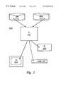
- FIG. 1is a pictorial representation depicting a telephone carrier network according to one embodiment of the present invention
- FIG. 2is a block diagram depicting a data processing system utilized in telecommunications networks in accordance with one embodiment of the present invention
- FIG. 3 ais a block diagram depicting one embodiment of the physical component of a carrier switch in accordance with the present invention.
- FIG. 3 bis a block diagram depicting another embodiment of the physical component of a carrier switch in accordance with the present invention.
- FIG. 4is a block diagram depicting the network setup in accordance with one embodiment of the present invention.
- FIG. 5is a chart depicting the logic flow when the edge switch receives the setup message from the caller in accordance with one embodiment of the invention
- FIG. 6is a chart depicting the logic flow when the edge switch receives the setup message from the H.323 gateway in accordance with one embodiment of the invention.
- FIG. 7is an illustration of a call log table in accordance with one embodiment of the invention.
- FIG. 8is a chart depicting the logic flow when the edge switch receives a particular message in accordance with one embodiment of the invention.
- FIG. 9is a chart depicting the logic flow when the edge switch receives the answer message in accordance with one embodiment of the invention.
- FIG. 10is a chart depicting the logic flow when the edge switch receives the setup message from the network in accordance with one embodiment of the invention.
- FIG. 11is a chart depicting the logic flow when the edge switch receives a warning message from the H.323 gateway in accordance with one embodiment of the invention.
- Telecommunications system 100 in FIG. 1includes a telecommunications network 102 , also called a “Telco Network”.
- Telecommunications network 102may be, for example, a Local Exchange Carrier (LEC), an Interexchange Carrier (IEC), or a hybrid network.
- LECLocal Exchange Carrier
- IECInterexchange Carrier
- hybrid networksuch a network may include landline and/or wireless telecommunications systems.
- the IECis the service provider for the call within telecommunications network 102 .
- Telecommunications network 102also includes a number of switches 104 a - 104 c , which provides establishing and routing a call between source Customer Premises Equipment (CPE) 106 and target CPE 108 .
- CPECustomer Premises Equipment
- Switches 104 a - 104 cinterconnect transmission facilities and are employed to route traffic throughout telecommunications network 102 .
- Transmission facilitiesprovide telecommunications paths 110 a - 110 c to carry a user's voice or other transmission data and network control information between switches in a network.
- transmission facilitiesinclude a medium, such as, for example, air, copper wires, coaxial cables, or fiber optic cables, along with electronic equipment employed to amplify and/or relay signals.
- CPEalso called subscriber or station equipment, is generally located at a user's premises.
- the depicted examplecontains three switches and three telecommunications paths for illustrative purposes only. Depending on the system, other numbers of switches, telecommunications paths, and configurations thereof may be employed.
- CPEThe function of CPE is to transmit and receive user information and exchange control information with telecommunications network 102 to place calls and access services from telecommunications network 102 .
- CPEmay be a telecommunications unit, such as, for example, a telephone, a computer, or a fax machine.
- the process of the present inventionmay be implemented in a data processing system within telecommunications network 102 .
- the data processing systemmay be implemented as a switch or as a computer having a connection to the switch.
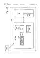
- Data processing system 200is an example of a data processing system in which a preferred embodiment of the present invention may be implemented.
- data processing system 200 in FIG. 2contains hardware that is depicted in functional units in accordance with a preferred embodiment of the present invention.
- Some of the functional units described below for data processing system 200may be configured in different physical units depending on the implementation. Examples of physical implementations are described below with reference to FIGS. 3A and 3B.
- data processing system 200contains switch intelligence (SI) 202 , which includes the logic for call processing and providing pre-call information in accordance with the preferred embodiment of the present invention.
- data processing system 200includes switch fabric (SF) 204 , which contains the telecommunications links and other switch hardware utilized to connect callers to the switch and to each other.
- Voice server (VS) 208contains multiple independent voice channels or paths for sending messages. In the depicted example, each of the voice channels are referred to as voice ports. For example, voice server 208 may contain three voice ports identified as VP 1 , VP 2 , and VP 3 .
- Data processing system 200also includes a dual tone multi frequency (DTMF) detector 210 for detecting DTMF tones that may be transmitted by a user.
- DTMFdual tone multi frequency
- Customer database (CDB) 212is a database containing information on customers utilized to determine charges for calls from a source location to various target locations. Different customers may have different rates in effect based on the particular plan subscribed to by the customer. Additionally, rates also may vary depending on factors, such as, for example, the time at which a call is placed, the geographic location of the calling party and of the called party, currently activated special features, and discounts currently in effect for a particular customer. Depending on the long distance or cellular service selected by the customer and the particular plan chosen, different customers may have different rates even though they initiate calls at the same time of the day to the same geographic location. This customer database may serve as the call log table utilized in accordance with the preferred embodiment of the present invention.
- Routing information database (RIDB) 214is a database containing routing information for call processing.
- the processes of the present inventionmay be implemented in a data processing system, such as a switch.
- the present inventionalso may be implemented in other data processing systems.
- the processes of the present inventionmay be implemented within a computer having a connection to a switch in which the computer provides the logic and commands to the switch to provide the processes utilized to provide post call charge information to a customer.
- FIG. 3Ais a block diagram of switch 300 , which is representative of the DMS family of switch products available from Northern Telecom.
- Switch 300 in FIG. 3Amay be implemented within telecommunications system 100 , in switches such as switches 104 a , 104 b , or 104 c in FIG. 1 .
- switch 300includes unit 302 connected to intelligent peripheral 304 .
- Unit 302contains a computing module (CM) 306 , which provides switch intelligent functions for switch 300 .
- Computing module 306contains processing unit 308 and memory 310 .
- Processing unit 308may contain, for example, one or more microprocessors for executing instructions to provide logic for call processing and processes for providing post call charge information in accordance with the preferred embodiment of the present invention.
- Memory 310stores instructions and data and may include random access memory (RAM) and/or read only memory (ROM).
- Unit 302also includes enhanced network (ENET) 312 , which provides a switch fabric function.
- Digital receiver 316provides DTMF functions.
- Unit 302also contains RIDB 214 .
- Voice server functionsare provided by intelligent peripheral (IP) 304 .
- intelligent peripheral 304also contains digital receiver 320 .
- Digital receivers 316 and 320may provide voice recognition functions in place of or in addition to recognizing DTMF tones.
- Switch 300has a connection to customer database (CDB) 212 , which is external to switch 300 .
- Customer database 212is in communication with unit 302 through enhanced network 312 .
- intelligent network 350is representative of an International Telecommunications Union switch defined by ITU-T Q. 1200 .
- Intelligent network 350includes a service control point (SCP) 352 , which is the switch intelligence for intelligent network 350 .
- SCPservice control point
- Within service control point 352is a processor unit 354 and a memory 310 .
- service control point 352also contains RIDB 214 .
- Intelligent network 350also contains a service switch platform (SSP) 362 , which provides switch fabric functions.
- Specialized resource functions (SRFs) 364 and 366are found within service switch platform 362 .
- Specialized resource function (SRF) 364provides DTMF functions for recognizing signals from consumer premises equipment.
- Intelligent peripheral (IP) 304also is a part of intelligent network 350 and provides voice server function.
- specialized resource function 370which also serves to provide DTMF functions.
- specialized resource function 364 and 366may be employed to provide voice recognition in place of, or in addition to, recognizing DTMF tones.
- Specialized service control point 352is in communication with CDB 212 , which is external to intelligent network 350 .
- the carrier networksis connected to the IP network as depicted in FIG. 4 .
- the carrier edge switches of the originating point and the destination pointare connected to the IP network via H.323 gateways, respectively.
- FIG. 4depicts general network setup according to the preferred embodiment of the present invention.
- Incoming calls 1102are processed by carrier edge switch 1104 a .
- Carrier edge switch 1104 ais a special switching device utilized by carriers to route calls from one point to another as illustrated in FIG. 1 .
- Carrier edge switch 1104 ain turn is connected to telephone network 1108 at the origination point.
- Telephone network 1108is then connected at the destination end to another carrier edge switch 1104 b , which processes the signals received and directs the outgoing call 1112 to its intended destination.
- carrier edge switches 1104 a and 1104 bare also connected to IP network 1110 via H.323 gateways 1106 a and 1106 b .
- H.323 gateway 1106 arepresents the entry node to IP network 1110 .
- H.323 gateway 1106 areceives messages from the source routed to IP network 1110 .
- Carrier edge switch 1104 a connected to origination H.323 gateway 1106 aroutes incoming calls 1102 through IP network 1110 . The call is then communicated to destination H.323 gateway 1106 b . Destination H.323 gateway 1106 b is connected to outgoing carrier edge switch 1104 b . Outgoing call 1112 is sent to carrier edge switch 1104 b from where outgoing call 1112 is routed to its intended destination.
- selection of IP networkis completed by first identifying a special IP area code and IP country code.
- the IP area code and country codemay either be industry wide standard or proprietary, and is selected so that it is unique. It may be any combination of characters, (for example 999, 9*) except that it may not be a valid area code/country code already in use. In this illustrative embodiment, 999 is selected as the IP area code and IP country code.
- the dialing plan for domestic long distance callis 1+(IP area code)+(called party area code+called party phone number), and the dialing plan for international long distance call is 011+(IP country code )+(country code+called party area code+called party phone number).
- Other methods of selecting the IP networkare possible.
- the call flow for setupis as shown in FIG. 5 .
- the callis identified as going through IP network by digit analysis or pretranslation or other means of determining the routing.
- the IP bound callsare delegated to the H.323 gateway, but the address translation (from the called party phone number to the H.323 gateway attached to the terminating edge switch) is done by querying either the voice network database or the registered H.323 gatekeeper.
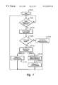
- FIG. 5depicts a logic flow diagram which shows the call setup process at the originating edge switch.
- the processbegins when a caller enters a number on origination CPE as illustrated in block 1202 .
- a setup messageis received from the caller as illustrated in block 1204 .
- the messageundergoes pretranslation or digit analysis as illustrated in block 1206 .
- This pretranslation or digit analysis from block 1206determines whether or not the user has entered digits (or a code) which will route the calls through the IP network.
- the carrier switchdetermines if the call is IP network bound as illustrated in block 1208 . If the call is to be routed through the IP network, then the carrier switch sets the call type as being IP bound as illustrated in block 1210 .
- Option onedelegates the call to the H.323 gateway as illustrated in block 1214 a .
- Option twofirst queries the switch database for address translation as illustrated in block 1216 . Then the call is delegated to the H.323 gateway as illustrated in block 1214 b . If the call is not IP network bound as illustrated in block 1208 , then normal call processing is setup as illustrated in block 1212 . The process then returns for the routing of the next call.
- FIG. 6depicts a call setup request from the destination H.323 gateway which is sent to the carrier edge switch at the terminating side of the call.
- the processstarts as illustrated in block 1302 .
- the setup messageis received from the H.323 gateway as illustrated in block 1304 .
- the terminating trunkis allocated as illustrated in block 1306 .
- An entryis then made into the call log table as illustrated in block 1308 to register the call as being routed through the IP network.
- FIG. 7shows a single row of data in the call log table. Entered into each row of data is the calling party number 402 , called party number 404 and the terminating trunk identifier (TID) 406 .
- TIDis an in-switch identifier for the outgoing trunk. This table will be utilized later for mid call features.
- the digit receiverAfter the call is answered for a voice call, the digit receiver is reattached for a minute or so in the preferred embodiment.
- the callerif the caller is not satisfied with the voice quality, he/she may dial a special key, for example “*”, to switch back to the circuit network.
- the carrier switchreceives the “*” key message, it detaches the receiver, allocates the terminating voice trunk and sends a setup request message over the terminator.
- the originating and terminating edge switchesshould behave as FIG. 8, FIG. 9 and FIG. 10, respectively, while the network switches behave as in setting up a normal call.
- the switchWhen the originating edge switch receives the answer message from the terminating edge switch, the switch will re-supervise the call for voice trunks and send a message to the H.323 gateway to terminate the IP connection for the call.
- the terminating edge switchAfter receiving a call setup request message from the network side, it will first check the in-switch call log table as illustrated in FIG. 7 . An entry in the call log table matching the calling and called party number indicates that the call was connected through the IP network. Once this is ascertained, the carrier switch sends an answer message to the originating edge switch to re-supervise the call for voice trunks, and sends a message to the attached H.322 gateway to terminate the IP connection for the call.
- FIG. 8depicts the logic flow when the edge switch receives the special message to terminate the IP connection.
- the processbegins at block 502 .
- the terminating trunkis allocated as illustrated as in block 506 , and a setup request message is sent over the terminating trunk as illustrated in block 508 .
- FIG. 9provides the actual process at the originating edge switch of terminating the IP connection, and resupervising the call over voice circuit. It begins in block 602 . If an answer message is received as illustrated in block 604 , a determination is made as to whether or not the call was an IP bound call type as illustrated in block 606 . If the call was an IP bound call type, then a message is sent to the H.323 gateway to terminate the IP connection as illustrated in block 608 . Once this is achieved, the origination and terminating trunk are supervised to establish voice path as illustrated in block 610 . Note that this occurs if the call type was an IP network routed call. If, however, the call was not IP network routed as illustrated in block 606 , then the process skips the messaging to terminate IP connection. The originating and terminating trunk are supervised and voice path is cut as illustrated in block 610 .
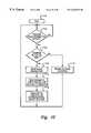
- FIG. 10depicts the process which occurs when the terminating edge switch receives the setup request message from the network.
- the processbegins in block 702 . If the setup message is received from the network as illustrated in block 704 , then a check is made to determine if a record of the call exists in the call log table as illustrated in block 706 . If there is no record of the call in the call log table, then the normal call setup processing begins as illustrated in block 710 . If however, the call log table does have data related to that call, then the answer message is sent back to the originating edge switch as illustrated in block 708 . The message is sent to the destination H.323 gateway and the IP connection is terminated for the call as illustrated in 712 . The origination and terminating trunks are supervised to establish the voice path as illustrated in block 714 .
- the gatewayif it detects too much packet loss during a voice call, it will send a warning message to the edge switch at the origination side.
- the edge switchWhen the edge switch receives the warning message, it will reattach the digit receiver for a limited time and send a beep to the calling party to give him/her a chance to switch to circuit network. If a special digit, for example “*”, is received, then the process to switch to circuit network as described in last section is activated.
- FIG. 11depicts the process which occurs when the gateway detects too much packet loss for call routed through the IP network.
- the processstarts in block 802 .
- H.323 gatewayreceives a warning message due to significant packet loss as illustrated in block 804 .
- thisprompts the reattachment of the digit receiver for a limited time as illustrated in block 806 to provide the caller with the option to terminate the IP routing and reroute via carrier network.
- a signalis transmitted to the caller as illustrated in block 808 to inform the caller he or she may terminate the IP connection and reselect the carrier network.
- the description of the preferred embodiment of the present inventionhas been presented for purposes of illustration and description, but is not intended to be exhaustive or limit the invention in the form disclosed.
- the processes of the present inventionare implemented in a switch
- the present inventionalso may be implemented in other data processing systems.
- the processes of the present inventionmay be implemented within a computer having a connection to a switch in which the computer provides the logic and commands to the switch to provide the processes utilized to determine post call charge information for a customer after termination of a call, which in the depicted examples are a long distance or cellular phone call.
- Many modifications and variationswill be apparent to those of ordinary skill in the art.
- the embodimentwas chosen and described in order to best explain the principles of the invention and the practical application to enable others of ordinary skill in the art to understand the invention for various embodiments with various as are suited to the particular use contemplated.
Landscapes
- Engineering & Computer Science (AREA)
- Computer Networks & Wireless Communication (AREA)
- Data Exchanges In Wide-Area Networks (AREA)
- Telephonic Communication Services (AREA)
- Facsimile Transmission Control (AREA)
- Facsimiles In General (AREA)
Abstract
Description
Claims (29)
Priority Applications (4)
| Application Number | Priority Date | Filing Date | Title |
|---|---|---|---|
| US09/201,997US6463053B1 (en) | 1998-12-01 | 1998-12-01 | Voice-and-fax-over IP dialing plan |
| CA002285873ACA2285873A1 (en) | 1998-12-01 | 1999-10-15 | Voice-and-fax-over ip dialing plan |
| JP11332272AJP2000174825A (en) | 1998-12-01 | 1999-11-24 | Communication control device and communication control method |
| EP99309496AEP1006738A3 (en) | 1998-12-01 | 1999-11-29 | Voice-and-fax-over-IP dialing plan |
Applications Claiming Priority (1)
| Application Number | Priority Date | Filing Date | Title |
|---|---|---|---|
| US09/201,997US6463053B1 (en) | 1998-12-01 | 1998-12-01 | Voice-and-fax-over IP dialing plan |
Publications (1)
| Publication Number | Publication Date |
|---|---|
| US6463053B1true US6463053B1 (en) | 2002-10-08 |
Family
ID=22748157
Family Applications (1)
| Application Number | Title | Priority Date | Filing Date |
|---|---|---|---|
| US09/201,997Expired - LifetimeUS6463053B1 (en) | 1998-12-01 | 1998-12-01 | Voice-and-fax-over IP dialing plan |
Country Status (4)
| Country | Link |
|---|---|
| US (1) | US6463053B1 (en) |
| EP (1) | EP1006738A3 (en) |
| JP (1) | JP2000174825A (en) |
| CA (1) | CA2285873A1 (en) |
Cited By (41)
| Publication number | Priority date | Publication date | Assignee | Title |
|---|---|---|---|---|
| US20010018656A1 (en)* | 2000-02-28 | 2001-08-30 | Hartmut Weik | Method and server for setting up a communication connection via an IP network |
| US20010053125A1 (en)* | 2000-04-04 | 2001-12-20 | Harry Staples | Fail-over circuit for voice-enabled switch |
| US20020041400A1 (en)* | 2000-09-26 | 2002-04-11 | Klaus Hunlich | Method for transporting facsimile information in IP-based networks |
| US20020071429A1 (en)* | 1999-11-08 | 2002-06-13 | Worldcom, Inc. | Internet protocol telephony voice/video message deposit and retrieval |
| US20030063729A1 (en)* | 2001-09-18 | 2003-04-03 | Mihael Oman | System and method for selecting a feature |
| US20030091024A1 (en)* | 2001-09-27 | 2003-05-15 | Siemens Information And Communications Networks, Inc. | Transparent interchangeable network (TIN) |
| US20030152210A1 (en)* | 2002-02-14 | 2003-08-14 | Mark Delaney | Call routing system |
| US20030200260A1 (en)* | 1999-11-08 | 2003-10-23 | Worldcom, Inc. | SIP-based feature control |
| US20030214940A1 (en)* | 2002-05-16 | 2003-11-20 | Takken Todd E. | Internet telephony system for enabling internet telephone access from traditional telephone interface |
| US6683868B1 (en)* | 1998-12-10 | 2004-01-27 | Alcatel | Gateway making it possible to develop new services independently from the underlying network |
| US6707827B1 (en)* | 1999-11-12 | 2004-03-16 | Siemens Information & Communication Networks, Inc. | Method and apparatus for optimizing audio response in telephony-over-LAN systems |
| US6735209B1 (en) | 1999-07-29 | 2004-05-11 | Worldcom, Inc. | Address definition for IP telephony services |
| US6735617B1 (en)* | 2000-08-10 | 2004-05-11 | Bbnt Solutions Llc | Routing T-37 E-mail over an H 323 (VOIP) network |
| US6771637B1 (en)* | 1999-02-16 | 2004-08-03 | Fujitsu Limited | Gateway apparatus |
| US6788667B1 (en)* | 2000-06-20 | 2004-09-07 | Nokia Corporation | Wireless access to wired network audio services using mobile voice call |
| US20040240638A1 (en)* | 1999-11-08 | 2004-12-02 | Donovan Steven R. | Methods for providing prepaid telephony service via an internet protocol network system |
| US20040258239A1 (en)* | 1999-11-08 | 2004-12-23 | Gallant John K. | Method and system for dynamic gateway selection in an IP telephony network |
| US6842452B1 (en)* | 2000-11-15 | 2005-01-11 | Intel Corporation | Method for switching data streams |
| US6842447B1 (en)* | 1999-06-14 | 2005-01-11 | Mci, Inc. | Internet protocol transport of PSTN-to-PSTN telephony services |
| US6879680B2 (en) | 1999-07-29 | 2005-04-12 | Mc, Inc. | Method of and system for extending internet telephony over virtual private network direct access lines |
| US20050141493A1 (en)* | 1998-12-24 | 2005-06-30 | Hardy William C. | Real time monitoring of perceived quality of packet voice transmission |
| US6937612B1 (en)* | 1998-07-03 | 2005-08-30 | Nortel Networks Limited | Communications method and apparatus |
| US20050265322A1 (en)* | 1999-10-04 | 2005-12-01 | Rex Hester | Enabling quality voice communications from web page call control |
| US20060126529A1 (en)* | 1998-12-24 | 2006-06-15 | Mci, Inc. | Determining the effects of new types of impairments on perceived quality of a voice service |
| US7065069B1 (en)* | 2000-09-12 | 2006-06-20 | Lucent Technologies Inc. | System for interconnecting circuit-based terminal devices with packet-based terminal devices in a voice communication connection |
| US20060153108A1 (en)* | 2002-03-25 | 2006-07-13 | Allied Telesis Kabushiki Kaigha | VoIP terminal capable of facsimile communication and communication method thereof |
| US7110395B1 (en)* | 2000-10-31 | 2006-09-19 | Cisco Technology, Inc. | Method and apparatus for network telephony |
| US20070127455A1 (en)* | 2005-12-07 | 2007-06-07 | Ricoh Company, Limited | Call control server |
| US20070133396A1 (en)* | 1998-08-03 | 2007-06-14 | Siemens Aktiengesellschaft | Method for re-routing data packets onto an alternative network |
| US7330460B1 (en)* | 2000-09-12 | 2008-02-12 | Lucent Technologies Inc. | Method and apparatus for providing efficient VoIP gateway-to-gateway communication |
| US7355988B1 (en)* | 2001-03-08 | 2008-04-08 | Cisco Technology, Inc. | Application server having asynchronous event manager configured for terminating messaging operations and rolling back prescribed data structures |
| US20080247386A1 (en)* | 2007-04-04 | 2008-10-09 | Cisco Technology, Inc. | Fax relay tunneling |
| US20090109495A1 (en)* | 2007-10-26 | 2009-04-30 | James Jackson | Methods and apparatus to route fax calls in an internet protocol (ip) multimedia subsystem (ims) network |
| US20100039679A1 (en)* | 2005-11-18 | 2010-02-18 | The Go Daddy Group, Inc. | Presenting Relevant Messages Associated with Incoming Fax Documents Using Previous Facsimile |
| US20100039675A1 (en)* | 2005-11-18 | 2010-02-18 | The Go Daddy Group, Inc. | Relevant Messages Associated with Outgoing Fax Documents Using Previous Facsimile |
| US20100046503A1 (en)* | 1997-07-24 | 2010-02-25 | Oki Electric Industry Co., Ltd. | Concentrator for speech telephones and method of communication over lan using same |
| US7860114B1 (en) | 1999-11-08 | 2010-12-28 | Verizon Business Global Llc | Method and system for dynamic gateway selection in an IP telephony network |
| US20130065598A1 (en)* | 2001-12-13 | 2013-03-14 | At&T Intellectual Property I, L.P. | Local Point of Presence |
| US9281996B1 (en) | 1999-11-08 | 2016-03-08 | Verizon Patent And Licensing Inc. | Method and system for dynamic gateway selection in an IP telephony network |
| US20170111263A1 (en)* | 2014-08-29 | 2017-04-20 | Ntt Docomo, Inc. | Communication system, route selection apparatus, and route selection method |
| US9661142B2 (en) | 2003-08-05 | 2017-05-23 | Ol Security Limited Liability Company | Method and system for providing conferencing services |
Families Citing this family (12)
| Publication number | Priority date | Publication date | Assignee | Title |
|---|---|---|---|---|
| US6865604B2 (en) | 1998-08-26 | 2005-03-08 | Sts Software Systems Ltd. | Method for extracting a computer network-based telephone session performed through a computer network |
| WO2002003714A1 (en)* | 2000-06-29 | 2002-01-10 | Bellsouth Intellectual Property Corporation | Voice-over-ip call forwarding |
| JP3501733B2 (en) | 2000-07-03 | 2004-03-02 | 日本電気通信システム株式会社 | Internet information communication system and Internet line connection method |
| JP3471305B2 (en) | 2000-09-18 | 2003-12-02 | エヌ・ティ・ティ・コムウェア株式会社 | A routing method integrating a telephone network and an IP network, and an exchange of the telephone network using the routing method |
| JP2002344497A (en) | 2001-05-18 | 2002-11-29 | Fujitsu Ltd | Connection route switching control method between media gateway devices and call agent device |
| JP4330297B2 (en)* | 2001-09-21 | 2009-09-16 | シャープ株式会社 | Call terminal |
| DE10158822B4 (en)* | 2001-11-30 | 2006-06-08 | Siemens Ag | A method for providing features for alternative connections of primary connections |
| US7366110B2 (en) | 2004-09-30 | 2008-04-29 | Avaya Technology Corp. | Method and apparatus for merging call components during call reconstruction |
| US7564793B2 (en) | 2005-01-04 | 2009-07-21 | Avaya Inc. | In-band call association signaling for a single number destination |
| US7613106B2 (en) | 2005-01-04 | 2009-11-03 | Avaya Inc. | Dial plan transparency for fragmented networks |
| US8462637B1 (en) | 2005-01-04 | 2013-06-11 | Sheridan Ross P.C. | Dial plan routing for fragmented networks |
| JP2010147981A (en)* | 2008-12-22 | 2010-07-01 | Nec Engineering Ltd | Ip-pbx system |
Citations (12)
| Publication number | Priority date | Publication date | Assignee | Title |
|---|---|---|---|---|
| EP0848560A2 (en) | 1996-12-13 | 1998-06-17 | Siemens Business Communication Systems, Inc. | Method and system for increasing quality of service at or below a treshold cost |
| WO1998048542A1 (en) | 1997-04-22 | 1998-10-29 | Bell Communications Research, Inc. | Apparatus and method for internet telephony routing |
| EP0907280A2 (en) | 1997-10-02 | 1999-04-07 | Siemens Business Communication Systems, Inc. | Alternative telephone call routing system |
| WO1999029123A2 (en) | 1997-12-01 | 1999-06-10 | Telefonaktiebolaget Lm Ericsson | Method for improving the setup of telephone-to-telephone calls |
| US5995607A (en)* | 1998-10-14 | 1999-11-30 | Siemens Information And Communication Networks, Inc. | Enhanced telephony trunk routing |
| US6069890A (en)* | 1996-06-26 | 2000-05-30 | Bell Atlantic Network Services, Inc. | Internet telephone service |
| US6075783A (en)* | 1997-03-06 | 2000-06-13 | Bell Atlantic Network Services, Inc. | Internet phone to PSTN cellular/PCS system |
| US6147971A (en)* | 1998-11-18 | 2000-11-14 | 3Com Corporation | Optimized routing method based on minimal hop count for use in PNNI based asynchronous transfer mode networks |
| US6253249B1 (en)* | 1998-08-31 | 2001-06-26 | Nortel Networks Limited | Method and devices for bridging data and telephone networks |
| US6292478B1 (en)* | 1996-11-21 | 2001-09-18 | Bell Atlantic Network Services, Inc. | Telecommunications system |
| US6304565B1 (en)* | 1998-05-20 | 2001-10-16 | At&T Corp. | Method of completing long distance pots calls with IP telephony endpoints |
| US6324280B2 (en)* | 1998-05-05 | 2001-11-27 | Lucent Technologies, Inc. | Optimum routing of calls over the public switched telephone network and the internet |
- 1998
- 1998-12-01USUS09/201,997patent/US6463053B1/ennot_activeExpired - Lifetime
- 1999
- 1999-10-15CACA002285873Apatent/CA2285873A1/ennot_activeAbandoned
- 1999-11-24JPJP11332272Apatent/JP2000174825A/enactivePending
- 1999-11-29EPEP99309496Apatent/EP1006738A3/ennot_activeWithdrawn
Patent Citations (12)
| Publication number | Priority date | Publication date | Assignee | Title |
|---|---|---|---|---|
| US6069890A (en)* | 1996-06-26 | 2000-05-30 | Bell Atlantic Network Services, Inc. | Internet telephone service |
| US6292478B1 (en)* | 1996-11-21 | 2001-09-18 | Bell Atlantic Network Services, Inc. | Telecommunications system |
| EP0848560A2 (en) | 1996-12-13 | 1998-06-17 | Siemens Business Communication Systems, Inc. | Method and system for increasing quality of service at or below a treshold cost |
| US6075783A (en)* | 1997-03-06 | 2000-06-13 | Bell Atlantic Network Services, Inc. | Internet phone to PSTN cellular/PCS system |
| WO1998048542A1 (en) | 1997-04-22 | 1998-10-29 | Bell Communications Research, Inc. | Apparatus and method for internet telephony routing |
| EP0907280A2 (en) | 1997-10-02 | 1999-04-07 | Siemens Business Communication Systems, Inc. | Alternative telephone call routing system |
| WO1999029123A2 (en) | 1997-12-01 | 1999-06-10 | Telefonaktiebolaget Lm Ericsson | Method for improving the setup of telephone-to-telephone calls |
| US6324280B2 (en)* | 1998-05-05 | 2001-11-27 | Lucent Technologies, Inc. | Optimum routing of calls over the public switched telephone network and the internet |
| US6304565B1 (en)* | 1998-05-20 | 2001-10-16 | At&T Corp. | Method of completing long distance pots calls with IP telephony endpoints |
| US6253249B1 (en)* | 1998-08-31 | 2001-06-26 | Nortel Networks Limited | Method and devices for bridging data and telephone networks |
| US5995607A (en)* | 1998-10-14 | 1999-11-30 | Siemens Information And Communication Networks, Inc. | Enhanced telephony trunk routing |
| US6147971A (en)* | 1998-11-18 | 2000-11-14 | 3Com Corporation | Optimized routing method based on minimal hop count for use in PNNI based asynchronous transfer mode networks |
Cited By (85)
| Publication number | Priority date | Publication date | Assignee | Title |
|---|---|---|---|---|
| US20100046503A1 (en)* | 1997-07-24 | 2010-02-25 | Oki Electric Industry Co., Ltd. | Concentrator for speech telephones and method of communication over lan using same |
| US8379633B2 (en)* | 1997-07-24 | 2013-02-19 | Oki Electric Industry Co., Ltd. | Concentrator for speech telephones and method of communication over LAN using same |
| US6937612B1 (en)* | 1998-07-03 | 2005-08-30 | Nortel Networks Limited | Communications method and apparatus |
| US7239631B1 (en)* | 1998-08-03 | 2007-07-03 | Siemens Aktiengesellschaft | Method for re-routing data packets onto an alternative network |
| US20070133396A1 (en)* | 1998-08-03 | 2007-06-14 | Siemens Aktiengesellschaft | Method for re-routing data packets onto an alternative network |
| US6683868B1 (en)* | 1998-12-10 | 2004-01-27 | Alcatel | Gateway making it possible to develop new services independently from the underlying network |
| US8689105B2 (en) | 1998-12-24 | 2014-04-01 | Tekla Pehr Llc | Real-time monitoring of perceived quality of packet voice transmission |
| US9571633B2 (en) | 1998-12-24 | 2017-02-14 | Ol Security Limited Liability Company | Determining the effects of new types of impairments on perceived quality of a voice service |
| US20090175188A1 (en)* | 1998-12-24 | 2009-07-09 | Verizon Business Global Llc | Real-time monitoring of perceived quality of packet voice transmission |
| US7653002B2 (en) | 1998-12-24 | 2010-01-26 | Verizon Business Global Llc | Real time monitoring of perceived quality of packet voice transmission |
| US8068437B2 (en)* | 1998-12-24 | 2011-11-29 | Verizon Business Global Llc | Determining the effects of new types of impairments on perceived quality of a voice service |
| US20060126529A1 (en)* | 1998-12-24 | 2006-06-15 | Mci, Inc. | Determining the effects of new types of impairments on perceived quality of a voice service |
| US20050141493A1 (en)* | 1998-12-24 | 2005-06-30 | Hardy William C. | Real time monitoring of perceived quality of packet voice transmission |
| US6771637B1 (en)* | 1999-02-16 | 2004-08-03 | Fujitsu Limited | Gateway apparatus |
| US8687625B2 (en) | 1999-06-14 | 2014-04-01 | Verizon Business Global Llc | Internet protocol transport of PSTN-to-PSTN telephony services |
| US6842447B1 (en)* | 1999-06-14 | 2005-01-11 | Mci, Inc. | Internet protocol transport of PSTN-to-PSTN telephony services |
| US7653081B2 (en) | 1999-06-14 | 2010-01-26 | Verizon Business Global Llc | Internet protocol transport of PSTN-to-PSTN telephony services |
| US20040151194A1 (en)* | 1999-07-29 | 2004-08-05 | Mciworldcom, Inc. | Address definition for IP telephony services |
| US7492775B2 (en) | 1999-07-29 | 2009-02-17 | Verizon Business Global Llc | Address definition for IP telephony services |
| US6879680B2 (en) | 1999-07-29 | 2005-04-12 | Mc, Inc. | Method of and system for extending internet telephony over virtual private network direct access lines |
| US6735209B1 (en) | 1999-07-29 | 2004-05-11 | Worldcom, Inc. | Address definition for IP telephony services |
| US6973091B1 (en)* | 1999-10-04 | 2005-12-06 | Hester Rex R | Enabling quality voice communications from web page call control |
| US8130750B2 (en) | 1999-10-04 | 2012-03-06 | Rex Hester | Enabling quality voice communications from web page call control |
| US8537812B2 (en) | 1999-10-04 | 2013-09-17 | Infinet Global Communications, Inc. | Enabling quality voice communications from web page call control |
| US20050265322A1 (en)* | 1999-10-04 | 2005-12-01 | Rex Hester | Enabling quality voice communications from web page call control |
| US9281996B1 (en) | 1999-11-08 | 2016-03-08 | Verizon Patent And Licensing Inc. | Method and system for dynamic gateway selection in an IP telephony network |
| US20020071429A1 (en)* | 1999-11-08 | 2002-06-13 | Worldcom, Inc. | Internet protocol telephony voice/video message deposit and retrieval |
| US8923276B2 (en) | 1999-11-08 | 2014-12-30 | Tekla Pehr Llc | Internet protocol telephony voice/video message deposit and retrieval |
| US8509393B2 (en) | 1999-11-08 | 2013-08-13 | Tekla Pehr Llc | Internet protocol telephony voice/video message deposit and retrieval |
| US20040258239A1 (en)* | 1999-11-08 | 2004-12-23 | Gallant John K. | Method and system for dynamic gateway selection in an IP telephony network |
| US20040240638A1 (en)* | 1999-11-08 | 2004-12-02 | Donovan Steven R. | Methods for providing prepaid telephony service via an internet protocol network system |
| US7167468B2 (en) | 1999-11-08 | 2007-01-23 | Mci, Llc | Internet protocol telephony voice/video message deposit and retrieval |
| US20090238177A1 (en)* | 1999-11-08 | 2009-09-24 | Worldcom, Inc. | Internet protocol telephony voice/video message deposit and retrieval |
| US20090219925A1 (en)* | 1999-11-08 | 2009-09-03 | Worldcom, Inc. | Internet protocol telephony voice/video message deposit and retrieval |
| US20070121591A1 (en)* | 1999-11-08 | 2007-05-31 | Worldcom, Inc. | Internet protocol telephony voice/video message deposit and retrieval |
| US7860114B1 (en) | 1999-11-08 | 2010-12-28 | Verizon Business Global Llc | Method and system for dynamic gateway selection in an IP telephony network |
| US7010103B2 (en) | 1999-11-08 | 2006-03-07 | Mci, Inc. | Methods for providing prepaid telephony service via an internet protocol network system |
| US20030200260A1 (en)* | 1999-11-08 | 2003-10-23 | Worldcom, Inc. | SIP-based feature control |
| US7844039B2 (en) | 1999-11-08 | 2010-11-30 | Verizon Business Global Llc | Methods for providing prepaid telephony service via an internet protocol network system |
| US7779072B2 (en) | 1999-11-08 | 2010-08-17 | Verizon Business Global Llc | SIP-based feature control |
| US7773585B2 (en) | 1999-11-08 | 2010-08-10 | Verizon Business Global Llc | Internet protocol telephony voice/video message deposit and retrieval |
| US8731158B2 (en) | 1999-11-08 | 2014-05-20 | Verizon Business Global Llc | Methods for providing prepaid telephony service via an internet protocol network system |
| US20090110164A1 (en)* | 1999-11-08 | 2009-04-30 | Donovan Steven R | Methods for providing prepaid telephony service via an internet protocol network system |
| US8743892B2 (en) | 1999-11-08 | 2014-06-03 | Verizon Business Global Llc | Method and system for dynamic gateway selection in an IP telephony network |
| US6707827B1 (en)* | 1999-11-12 | 2004-03-16 | Siemens Information & Communication Networks, Inc. | Method and apparatus for optimizing audio response in telephony-over-LAN systems |
| US20010018656A1 (en)* | 2000-02-28 | 2001-08-30 | Hartmut Weik | Method and server for setting up a communication connection via an IP network |
| US20010053125A1 (en)* | 2000-04-04 | 2001-12-20 | Harry Staples | Fail-over circuit for voice-enabled switch |
| US6788667B1 (en)* | 2000-06-20 | 2004-09-07 | Nokia Corporation | Wireless access to wired network audio services using mobile voice call |
| US7921161B2 (en) | 2000-08-10 | 2011-04-05 | Verizon Corporate Services Group Inc. | Routing T-37 E-mail over an H 323 (VOIP) network |
| US6735617B1 (en)* | 2000-08-10 | 2004-05-11 | Bbnt Solutions Llc | Routing T-37 E-mail over an H 323 (VOIP) network |
| US20050086312A1 (en)* | 2000-08-10 | 2005-04-21 | Goodman Lee N. | Routing T-37 E-mail over an H 323 (VOIP) network |
| US7065069B1 (en)* | 2000-09-12 | 2006-06-20 | Lucent Technologies Inc. | System for interconnecting circuit-based terminal devices with packet-based terminal devices in a voice communication connection |
| US7330460B1 (en)* | 2000-09-12 | 2008-02-12 | Lucent Technologies Inc. | Method and apparatus for providing efficient VoIP gateway-to-gateway communication |
| US20020041400A1 (en)* | 2000-09-26 | 2002-04-11 | Klaus Hunlich | Method for transporting facsimile information in IP-based networks |
| US7110395B1 (en)* | 2000-10-31 | 2006-09-19 | Cisco Technology, Inc. | Method and apparatus for network telephony |
| US6842452B1 (en)* | 2000-11-15 | 2005-01-11 | Intel Corporation | Method for switching data streams |
| US7355988B1 (en)* | 2001-03-08 | 2008-04-08 | Cisco Technology, Inc. | Application server having asynchronous event manager configured for terminating messaging operations and rolling back prescribed data structures |
| US20030063729A1 (en)* | 2001-09-18 | 2003-04-03 | Mihael Oman | System and method for selecting a feature |
| US7190776B2 (en)* | 2001-09-18 | 2007-03-13 | Siemens Aktiengesellschaft | System and method for selecting a feature |
| US20030091024A1 (en)* | 2001-09-27 | 2003-05-15 | Siemens Information And Communications Networks, Inc. | Transparent interchangeable network (TIN) |
| US7382767B2 (en)* | 2001-09-27 | 2008-06-03 | Siemens Communications, Inc. | Transparent interchangeable network (TIN) |
| US8942711B2 (en)* | 2001-12-13 | 2015-01-27 | At&T Intellectual Property I, L.P. | Local point of presence |
| US20130065598A1 (en)* | 2001-12-13 | 2013-03-14 | At&T Intellectual Property I, L.P. | Local Point of Presence |
| US7212622B2 (en)* | 2002-02-14 | 2007-05-01 | Itxc Ip Holdings Sarl | Call routing system |
| US20030152210A1 (en)* | 2002-02-14 | 2003-08-14 | Mark Delaney | Call routing system |
| US20060153108A1 (en)* | 2002-03-25 | 2006-07-13 | Allied Telesis Kabushiki Kaigha | VoIP terminal capable of facsimile communication and communication method thereof |
| US9112953B2 (en) | 2002-05-16 | 2015-08-18 | International Business Machines Corporation | Internet telephony unit and software for enabling internet telephone access from traditional telephone interface |
| US8295270B2 (en)* | 2002-05-16 | 2012-10-23 | International Business Machines Corporation | Internet telephony system for enabling internet telephone access from traditional telephone interface |
| US20030214940A1 (en)* | 2002-05-16 | 2003-11-20 | Takken Todd E. | Internet telephony system for enabling internet telephone access from traditional telephone interface |
| US9661142B2 (en) | 2003-08-05 | 2017-05-23 | Ol Security Limited Liability Company | Method and system for providing conferencing services |
| US20100039675A1 (en)* | 2005-11-18 | 2010-02-18 | The Go Daddy Group, Inc. | Relevant Messages Associated with Outgoing Fax Documents Using Previous Facsimile |
| US20100046037A1 (en)* | 2005-11-18 | 2010-02-25 | The Go Daddy Group, Inc. | Presenting Relevant Messages Associated with Incoming Fax Documents Using Multiple Facsimiles |
| US20100039678A1 (en)* | 2005-11-18 | 2010-02-18 | The Go Daddy Group, Inc. | Presenting Relevant Messages Associated with Incoming Fax Documents |
| US20100039676A1 (en)* | 2005-11-18 | 2010-02-18 | The Go Daddy Group, Inc. | Relevant Messages Associated with Incoming Fax Documents Using Multiple Facsimiles |
| US20100039674A1 (en)* | 2005-11-18 | 2010-02-18 | The Go Daddy Group, Inc. | Relevant Messages Associated with Outgoing Fax Documents Using Multiple Facsimiles |
| US20100039677A1 (en)* | 2005-11-18 | 2010-02-18 | The Go Daddy Group, Inc. | Relevant Messages Associated with Incoming Fax Documents Using Previous Facsimile |
| US20100039679A1 (en)* | 2005-11-18 | 2010-02-18 | The Go Daddy Group, Inc. | Presenting Relevant Messages Associated with Incoming Fax Documents Using Previous Facsimile |
| US9473622B2 (en)* | 2005-12-07 | 2016-10-18 | Ricoh Company, Limited | Call control server |
| US20070127455A1 (en)* | 2005-12-07 | 2007-06-07 | Ricoh Company, Limited | Call control server |
| US8582557B2 (en)* | 2007-04-04 | 2013-11-12 | Cisco Technology, Inc. | Fax relay tunneling |
| US20080247386A1 (en)* | 2007-04-04 | 2008-10-09 | Cisco Technology, Inc. | Fax relay tunneling |
| US20090109495A1 (en)* | 2007-10-26 | 2009-04-30 | James Jackson | Methods and apparatus to route fax calls in an internet protocol (ip) multimedia subsystem (ims) network |
| US8130425B2 (en) | 2007-10-26 | 2012-03-06 | At&T Intellectual Property I, Lp | Methods and apparatus to route fax calls in an internet protocol (IP) multimedia subsystem (IMS) network |
| US20170111263A1 (en)* | 2014-08-29 | 2017-04-20 | Ntt Docomo, Inc. | Communication system, route selection apparatus, and route selection method |
| US10050871B2 (en)* | 2014-08-29 | 2018-08-14 | Ntt Docomo, Inc. | Communication system, route selection apparatus, and route selection method |
Also Published As
| Publication number | Publication date |
|---|---|
| CA2285873A1 (en) | 2000-06-01 |
| JP2000174825A (en) | 2000-06-23 |
| EP1006738A2 (en) | 2000-06-07 |
| EP1006738A3 (en) | 2002-01-09 |
Similar Documents
| Publication | Publication Date | Title |
|---|---|---|
| US6463053B1 (en) | Voice-and-fax-over IP dialing plan | |
| JP3940122B2 (en) | Method for forming usable features for alternate connections of primary connections | |
| EP0873637B1 (en) | Method and apparatus for implementing a computer network/internet telephone system | |
| EP1679866B1 (en) | Method and arrangement for providing communication over a computer network | |
| US6584094B2 (en) | Techniques for providing telephonic communications over the internet | |
| US6870827B1 (en) | Voice call alternative routing through PSTN and internet networks | |
| US6253249B1 (en) | Method and devices for bridging data and telephone networks | |
| US6985494B2 (en) | System for interconnecting standard telephony communications equipment to internet protocol networks | |
| US6064653A (en) | Internetwork gateway to gateway alternative communication | |
| US5933490A (en) | Overload protection for on-demand access to the internet that redirects calls from overloaded internet service provider (ISP) to alternate internet access provider | |
| JP3357591B2 (en) | Communication device and communication path selection method | |
| US6262978B1 (en) | Call completion of video telephone/teleconference call as packet voice call | |
| US6198738B1 (en) | Communications between the public switched telephone network and packetized data networks | |
| US20040028080A1 (en) | Method of defining a SIP message body for communications between core network elements | |
| WO1997016916A9 (en) | Method and apparatus for implementing a computer network/internet telephone system | |
| US6937593B1 (en) | System and method for servicing calls originating via the internet | |
| US8995434B2 (en) | System for interconnecting standard telephony communications equipment to internet | |
| US7110395B1 (en) | Method and apparatus for network telephony | |
| KR100362975B1 (en) | Method and apparatus to enable enhanced services of an intelligent telephone network in a wireless environment | |
| US7436851B1 (en) | Destination call routing apparatus and method | |
| US20050047402A1 (en) | End user selectable routing of packet or circuit-switched calls | |
| US20030016661A1 (en) | Telephone switching system for integrating the internet with the public switched telephone network | |
| US6427007B1 (en) | System and method for completing a call while at least one call is established using analog interface to telephone network | |
| CA2246192C (en) | Method and devices for bridging data and telephone networks | |
| US6539086B2 (en) | System and method for completing two calls using analog interface to telephone network |
Legal Events
| Date | Code | Title | Description |
|---|---|---|---|
| AS | Assignment | Owner name:NORTHERN TELECOM LIMITED, CANADA Free format text:ASSIGNMENT OF ASSIGNORS INTEREST;ASSIGNOR:CHEN, XIAO L.;REEL/FRAME:009649/0546 Effective date:19981125 | |
| AS | Assignment | Owner name:NORTEL NETWORKS CORPORATION, CANADA Free format text:CHANGE OF NAME;ASSIGNOR:NORTHERN TELECOM LIMITED;REEL/FRAME:010567/0001 Effective date:19990429 | |
| AS | Assignment | Owner name:NORTEL NETWORKS LIMITED, CANADA Free format text:CHANGE OF NAME;ASSIGNOR:NORTEL NETWORKS CORPORATION;REEL/FRAME:011195/0706 Effective date:20000830 Owner name:NORTEL NETWORKS LIMITED,CANADA Free format text:CHANGE OF NAME;ASSIGNOR:NORTEL NETWORKS CORPORATION;REEL/FRAME:011195/0706 Effective date:20000830 | |
| STCF | Information on status: patent grant | Free format text:PATENTED CASE | |
| FPAY | Fee payment | Year of fee payment:4 | |
| FPAY | Fee payment | Year of fee payment:8 | |
| AS | Assignment | Owner name:ROCKSTAR BIDCO, LP, NEW YORK Free format text:ASSIGNMENT OF ASSIGNORS INTEREST;ASSIGNOR:NORTEL NETWORKS LIMITED;REEL/FRAME:027164/0356 Effective date:20110729 | |
| AS | Assignment | Owner name:ROCKSTAR CONSORTIUM US LP, TEXAS Free format text:ASSIGNMENT OF ASSIGNORS INTEREST;ASSIGNOR:ROCKSTAR BIDCO, LP;REEL/FRAME:032111/0001 Effective date:20120509 | |
| AS | Assignment | Owner name:CONSTELLATION TECHNOLOGIES LLC, TEXAS Free format text:ASSIGNMENT OF ASSIGNORS INTEREST;ASSIGNOR:ROCKSTAR CONSORTIUM US LP;REEL/FRAME:032162/0524 Effective date:20131113 | |
| FPAY | Fee payment | Year of fee payment:12 | |
| AS | Assignment | Owner name:RPX CLEARINGHOUSE LLC, CALIFORNIA Free format text:ASSIGNMENT OF ASSIGNORS INTEREST;ASSIGNORS:ROCKSTAR CONSORTIUM US LP;ROCKSTAR CONSORTIUM LLC;BOCKSTAR TECHNOLOGIES LLC;AND OTHERS;REEL/FRAME:034924/0779 Effective date:20150128 | |
| AS | Assignment | Owner name:JPMORGAN CHASE BANK, N.A., AS COLLATERAL AGENT, IL Free format text:SECURITY AGREEMENT;ASSIGNORS:RPX CORPORATION;RPX CLEARINGHOUSE LLC;REEL/FRAME:038041/0001 Effective date:20160226 | |
| AS | Assignment | Owner name:RPX CORPORATION, CALIFORNIA Free format text:RELEASE (REEL 038041 / FRAME 0001);ASSIGNOR:JPMORGAN CHASE BANK, N.A.;REEL/FRAME:044970/0030 Effective date:20171222 Owner name:RPX CLEARINGHOUSE LLC, CALIFORNIA Free format text:RELEASE (REEL 038041 / FRAME 0001);ASSIGNOR:JPMORGAN CHASE BANK, N.A.;REEL/FRAME:044970/0030 Effective date:20171222 | |
| AS | Assignment | Owner name:JEFFERIES FINANCE LLC, NEW YORK Free format text:SECURITY INTEREST;ASSIGNOR:RPX CLEARINGHOUSE LLC;REEL/FRAME:046485/0644 Effective date:20180619 | |
| AS | Assignment | Owner name:RPX CLEARINGHOUSE LLC, CALIFORNIA Free format text:RELEASE BY SECURED PARTY;ASSIGNOR:JEFFERIES FINANCE LLC;REEL/FRAME:054305/0505 Effective date:20201023 |