US6462367B2 - RuSixOy-containing adhesion layers - Google Patents
RuSixOy-containing adhesion layersDownload PDFInfo
- Publication number
- US6462367B2 US6462367B2US09/888,891US88889101AUS6462367B2US 6462367 B2US6462367 B2US 6462367B2US 88889101 AUS88889101 AUS 88889101AUS 6462367 B2US6462367 B2US 6462367B2
- Authority
- US
- United States
- Prior art keywords
- rusi
- layer
- adhesion layer
- silicon
- ruthenium
- Prior art date
- Legal status (The legal status is an assumption and is not a legal conclusion. Google has not performed a legal analysis and makes no representation as to the accuracy of the status listed.)
- Expired - Lifetime
Links
Images

Classifications
- H—ELECTRICITY
- H10—SEMICONDUCTOR DEVICES; ELECTRIC SOLID-STATE DEVICES NOT OTHERWISE PROVIDED FOR
- H10D—INORGANIC ELECTRIC SEMICONDUCTOR DEVICES
- H10D1/00—Resistors, capacitors or inductors
- H10D1/60—Capacitors
- H10D1/68—Capacitors having no potential barriers
- H10D1/692—Electrodes
- H10D1/696—Electrodes comprising multiple layers, e.g. comprising a barrier layer and a metal layer
- H—ELECTRICITY
- H01—ELECTRIC ELEMENTS
- H01L—SEMICONDUCTOR DEVICES NOT COVERED BY CLASS H10
- H01L21/00—Processes or apparatus adapted for the manufacture or treatment of semiconductor or solid state devices or of parts thereof
- H01L21/70—Manufacture or treatment of devices consisting of a plurality of solid state components formed in or on a common substrate or of parts thereof; Manufacture of integrated circuit devices or of parts thereof
- H01L21/71—Manufacture of specific parts of devices defined in group H01L21/70
- H01L21/768—Applying interconnections to be used for carrying current between separate components within a device comprising conductors and dielectrics
- H01L21/76838—Applying interconnections to be used for carrying current between separate components within a device comprising conductors and dielectrics characterised by the formation and the after-treatment of the conductors
- H01L21/76841—Barrier, adhesion or liner layers
- H01L21/76843—Barrier, adhesion or liner layers formed in openings in a dielectric
- H—ELECTRICITY
- H10—SEMICONDUCTOR DEVICES; ELECTRIC SOLID-STATE DEVICES NOT OTHERWISE PROVIDED FOR
- H10D—INORGANIC ELECTRIC SEMICONDUCTOR DEVICES
- H10D1/00—Resistors, capacitors or inductors
- H10D1/60—Capacitors
- H10D1/68—Capacitors having no potential barriers
- H10D1/682—Capacitors having no potential barriers having dielectrics comprising perovskite structures
Definitions
- the present inventionrelates to semiconductor devices and the fabrication thereof More particularly, the present invention pertains to RuSi x O y -containing adhesion layers, structures incorporating such adhesion layers, and methods of fabricating the same.
- Integrated circuitstypically include various conductive layers.
- conductive materialse.g., electrode materials such as Pt and Ru
- interconnection structurese.g., conductive layers in contact holes, vias, etc.
- adhesion layerIn integrated circuits, conductive materials may require some sort of adhesion layer in order to prevent delamination of the films. In forming such integrated circuit structures, the adhesion layer must be able to withstand the various anneals performed on the capacitor electrode and dielectric. The adhesion of grown and deposited films used in semiconductor processing must be excellent both as deposited and after subsequent processing.
- failurecan result, leading to potential reliability problems.
- failure of the adhesivecan result in fracture of the mechanical bond (e.g., die separation) or failure of the circuit by degradation (e.g., contamination or loss of thermal or electrical properties) and could preclude the use of the desired film.
- tungstenis typically used as a contact fill material, which requires the use of an underlying contact layer as well as an underlying adhesion layer.
- the contact layeris needed to provide both good ohmic contact to the silicon device, and also serves as an adhesion layer between the tungsten fill and the sides of a silicon oxide contact hole. Titanium is usually used for this purpose, providing good ohmic contact, after centering converts titanium to titanium disilicide at the bottom of the contact hole.
- titanium adhesive layeris used, the subsequent tungsten chemical vapor deposition process severely damages the exposed titanium.
- the tungsten depositionis performed via the decomposition of tungsten hexafluoride, and in addition to the deposition of tungsten, a serious reaction with titanium occurs, eroding the critical contact and adhesive layer.
- an adhesion layer of either sputtered tungsten or titanium nitride on the titanium layerhas been suggested.
- U.S. Pat. No. 5,286,675describes a process in which a titanium-titanium nitride composite is used in contact holes prior to filling with tungsten.
- that processdoes not sufficiently eliminate the attack of titanium, particularly where poor titanium nitride coverage exists.
- the lack of adequate titanium nitride coverageleads to erosion of the underlying titanium adhesive layer during the subsequent tungsten deposition process, resulting in a lack of tungsten adhesion, which is described as “tungsten peeling” or the “volcano effect.”
- Adhesion layershave also been employed for providing adhesion between a substrate and overlying seed layers in metallization areas of substrates.
- U.S. Pat. No. 5,126,016provides a chromium adhesion layer for thin-film microelectronic circuitry.
- the metallization of high aspect ratio thin-film structurescause high stress which may lead to adhesions failure, as described above.
- metals and metallic compoundse.g., metals such as platinum and conductive metal oxides such as ruthenium oxide
- electrodes or electrode stack layers with high dielectric constant materialshave been proposed for use as electrodes or as electrode stack layers with high dielectric constant materials.
- electrical connectionsmust be constructed so as to not diminish the beneficial properties of the highdielectric constant materials.
- an oxidation-resistant barrier layer and adhesive layerare typically required.
- These layersmust provide adhesion between a substrate and deposited layers and prevent oxidation of silicon located at the surface of the electrode stack during the oxygen anneal of the high dielectric constant materials (e.g., Ta 2 O 5 or BaSrTiO 3 ), which oxidation can result in a decreased series capacitance and, in turn, degradation of the storage capacity of the cell capacitor.
- the high dielectric constant materialse.g., Ta 2 O 5 or BaSrTiO 3
- O 2 diffusing through the platinum or RuO 2 to the underlying Siyields SiO 2 at the base of the electrode, thus decreasing series capacitance.
- Platinum and ruthenium oxidewhen used alone as an electrode and adhered to, are generally too permeable to oxygen and silicon to be used as a bottom electrode of a storage cell capacitor formed on a silicon substrate region.
- an adhesion layerthat prevents delamination of deposited films contacting the same, withstands the various anneals performed on the capacitor electrode and dielectric, maintains the performance of high dielectric capacitors, prevents oxidation of underlying Si contacts, and prevents Si diffusion into an electrode or dielectric. It would be of further advantage to form an adhesion layer that can survive a tape test both as deposited and after an annealing step and that reduces or eliminates the diffusion or migration of ruthenium into an elemental Si or a silicide layer, or vice versa, which typically occurs as a result of the high solubility of silicon in ruthenium.
- the present inventionprovides RuSi x O y -containing adhesion layers, along with structures incorporating such adhesion layers and methods of fabricating the same.
- a method of fabricating semiconductor devices and assembliesincludes providing a substrate assembly having a surface.
- An adhesion layeris formed over at least a portion of the surface.
- the adhesion layerincludes RuSi x O y , where x and y are in the range of about 0.01 to about 10.
- the adhesion layermay, additionally, include Ru and/or RuSi x .
- the adhesion layeris formed of RuSi x O y , where x is in the range of about 0.1 to about 3, and more preferably is about 0.4, and where y is in the range of about 0.01 to about 0.1, and more preferably is about 0.05.
- the adhesion layeris formed by depositing a mixed film of Ru—RuSi x —RuSi x O y by chemical vapor deposition (CVD).
- the adhesion layeris formed by CVD deposition of Ru—RuSi x O y in an oxidizing atmosphere, such as O 2 , N 2 O, O 3 , or any other suitable inorganic or organic oxidizer. All of the foregoing adhesion layers may also be formed by atomic layer deposition.
- This processcan result in the formation of multiple (preferably up to 300) RuSi x O y -containing diffusion adhesion monolayers and, more preferably, formation of from three to five monolayers of RuSi x O y -containing adhesion layers.
- the adhesion layeris formed by physical vapor deposition (PVD) of the adhesion layers of the present invention.
- PVDphysical vapor deposition
- mixed films of Ru—RuSi x —RuSi x O yare deposited to form an adhesion layer.
- mixed films of Ru—RuSi x O ymay be deposited to form an adhesion layer.
- a capacitoris formed by providing a silicon-containing region of a substrate assembly.
- a first electrodeis then formed on at least a portion of the silicon-containing region of the substrate assembly.
- the first electrodeincludes an adhesion layer having RuSi x O y , where x and y are in the range of about 0.01 to about 10.
- a high dielectric materialis then formed over at least a portion of the first electrode and a second electrode is provided over the high dielectric material.
- the second electrodemay also include an adhesion layer having RuSi x O y , where x and y are in the range of about 0.01 to about 10.
- one or more conductive layersare formed relative to the RuSi x O y -containing adhesion layer.
- the one or more conductive layersare formed of at least one of a metal or a conductive metal oxide, e.g., formed from materials selected from the group of RuO 2 , RhO 2 , MoO 2 , IrO 2 , SrRuO 3 , Ru, Rh, Pd, Pt, and Ir.
- a semiconductor device structureincludes a substrate assembly including a surface and an adhesion layer over at least a portion of the surface.
- the adhesion layeris formed of RuSi x O y , where x and y are in the range of about 0.01 to about 10.
- the structureincludes one or more additional conductive layers over the adhesion layer formed of at least one of a metal and a conductive metal oxide, e.g., formed from materials selected from the group of RuO 2 , RhO 2 , MoO 2 , IrO 2 , Ru, Rh, Pd, Pt, and Ir.
- One embodiment of such a structureincludes a capacitor structure having a first electrode, a high dielectric material on at least a portion of the first electrode, and a second electrode on the dielectric material. At least one of the first and second electrodes includes an adhesion layer formed of RuSi x O y , where x and y are in the range of about 0.01 to about 10.
- Another such structureis an integrated circuit including a substrate assembly including at least one active device and a silicon-containing region.
- An interconnectis formed relative to the at least one active device and the silicon-containing region.
- the interconnectincludes an adhesion layer on at least a portion of the silicon-containing region.
- the adhesion layeris formed of RuSi x O y , where x and y are in the range of about 0.01 to about 10.
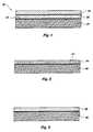
- FIG. 1shows a device structure including a RuSi x O y -containing adhesion layer according to the present invention
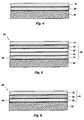
- FIGS. 2-4show one method of forming the RuSi x O y -containing adhesion layer according to the present invention
- FIG. 5shows a structure including a RuSi x O y -containing adhesion layer according to the present invention as part of a multiple conductive layer stack;
- FIG. 6is a structure showing a high dielectric capacitor including an electrode having a RuSi x O y -containing adhesion layer according to the present invention
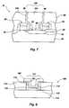
- FIG. 7illustrates the use of a RuSi x O y -containing adhesion layer in a storage cell capacitor application
- FIG. 8illustrates the use of a RuSi x O y -containing adhesion layer in a contact application.
- a structure 20includes a substrate assembly 21 and a RuSi x O y -containing adhesion layer 23 disposed on a surface 22 of the substrate assembly 21 , e.g., a silicon-containing substrate.
- the structure 20further includes a conductive layer 24 .
- substrate assemblyrefers to either a semiconductor substrate such as the base semiconductor layer (e.g., base silicon layer of a wafer), a silicon layer deposited on another material (e.g., silicon on sapphire), or a semiconductor substrate having one or more layers, structures, and/or regions formed thereon or therein. It is understood that reference to a substrate assembly herein also includes any known process steps that may have been previously used to form or define regions, junctions, various structures or features, and openings (e.g., vias, contact openings, high aspect ratio openings, etc.).
- the structure 20is representative of a RuSi x O y -containing adhesion layer that may be used for any application requiring an effective adhesion layer, for example, to adhere two adjacent layers together, prevent delamination of films in a semiconductor structure, and to prevent oxidation of an underlying Si contact.
- the RuSi x O y -containing adhesion layer 23may be used in the fabrication of semiconductor devices or assemblies where it is necessary or desirable to enhance or ensure adhesion of one material to an adjacent material. As described more fully hereinafter, the RuSi x O y -containing adhesion layer 23 may include Ru and/or RuSi x , in addition to RuSi x O y .
- the substrate assembly 21may, for example, be representative of a contact structure having an opening extending to a silicon-containing surface.
- adhesion layersare commonly used within the contact opening to prevent undesirable reactions, such as reactions between the conductive contact material and the silicon-containing surface that lead to erosion of one or both such layers and a general lack of adhesion between the contact and silicon-containing materials.
- the RuSi x O y -containing adhesion layer 23may be interposed between other layers of materials (e.g., ruthenium oxide, platinum, etc.) forming an electrode of a capacitor.
- adhesion layers of the present inventioncan be used in any semiconductor processes, structures, assemblies and devices (e.g., CMOS devices and memory devices) which utilize adhesion layers.
- the amount of elemental Si and SiO 2 incorporated into the RuSi x O y -containing adhesion layer 23is sufficient to accomplish adhesion and oxidation resistance in between one or more layers of materials in semiconductor devices.
- the RuSi x O y -containing adhesion layer 23includes an atomic composition such that x and y are in the range of about 0.01 to about 10. More preferably, x and y are in the range of about 1 to about 3, and yet more preferably, x is about 0.4 and y is about 0.05.
- the RuSi xincludes an atomic composition such that x is in the range of about 0.01 to about 10, and more preferably in the range of about 0.1 to about 0.5, and yet more preferably, x is about 0.4.
- the thickness of the RuSi x O y -containing adhesion layer 23is dependent upon the application for which it is used. Preferably, the thickness is in the range of about 10 ⁇ to 1,000 ⁇ . More preferably, the thickness of the RuSi x O y -containing adhesion layer 23 is in the range of about 50 ⁇ to about 500 ⁇ . For example, this preferred thickness range of about 50 ⁇ to about 500 ⁇ is applicable to a RuSi x O y -containing adhesion layer used for forming a bottom electrode stack of a capacitor structure.
- the conductive layer 24 shown in FIG. 1is representative of one or more layers.
- the conductive layer 24may include one or more layers formed of a metal or metal oxide, or combinations thereof. Such layers may include one of RuO 2 , MoO 2 , Rh, RhO 2 , IrO 2 , Ru, Pt, Pd and Ir, such as when the RuSi x O y -containing adhesion layer is used in an electrode stack.
- the conductive layer 24may be a contact material, such as aluminum, when the RuSi x O y -containing adhesion layer is used in a contact or interconnect application.
- Such conductive layersmay be formed by any method known to those skilled in the art.
- the RuSi x O y -containing adhesion layer 23may be formed by various processes.
- the formation of the RuSi x O y -containing adhesion layermay be sputter deposited from a deposition target of RuSi x O y , may be deposited by the sputtering from a deposition target of ruthenium onto a silicon-containing surface followed by an anneal, may be deposited by physical vapor deposition (PVD) of Ru—RuSi x —RuSi x O y mixed films, may be deposited by CVD using a ruthenium precursor and a silicon precursor in an oxidizing atmosphere, or may be deposited by CVD of Ru-RuSi x —RuSi x O y films.
- PVDphysical vapor deposition
- Suitable CVD processesinclude, for example, atmospheric pressure chemical vapor deposition (APCVD), low pressure chemical vapor deposition (LPCVD), plasma enhanced chemical vapor deposition (PECVD), or any other known chemical vapor deposition technique.
- APCVDatmospheric pressure chemical vapor deposition
- LPCVDlow pressure chemical vapor deposition
- PECVDplasma enhanced chemical vapor deposition
- the RuSi x O y -containing adhesion layermay be formed by depositing a layer of ruthenium using CVD onto a silicon-containing surface followed by an annealing process.
- the aforementioned CVD processesmay be carried out in a chemical vapor deposition reactor, such as a reaction chamber available under the trade designation of 7000 from Genus, Inc. (Sunnyvale, Calif.), a reaction chamber available under the trade designation of 5000 from Applied Materials, Inc. (Santa Clara, Calif.), or a reaction chamber available under the trade designation of Prism from Novelus, Inc. (San Jose, Calif.).
- a chemical vapor deposition reactorsuch as a reaction chamber available under the trade designation of 7000 from Genus, Inc. (Sunnyvale, Calif.), a reaction chamber available under the trade designation of 5000 from Applied Materials, Inc. (Santa Clara, Calif.), or a reaction chamber available under the trade designation of Prism from Novelus, Inc. (San Jose, Calif.).
- any reaction chamber suitable for performing CVDmay be used.
- Oxidizing agents for use in the CVD processmay be any gaseous reactant which is capable of reacting with the Ru precursor compounds at the decomposition temperatures of the latter to form Ru—RuSi x —RuSi x O y films.
- Suitable oxidizing agents for use with the present methodinclude, but are not limited to, air, oxygen, and oxygen-containing compounds, such as nitrous oxide, tetrahydrofuran, and carbon dioxide, and are preferably selected from mildly oxidizing gaseous oxygen sources.
- CVDmay be defined as the formation of a nonvolatile, solid film on a substrate by the reaction of vapor phase reactants, i.e., reactant gases, that contain desired components.
- the reactant gasesare introduced into the reaction chamber.
- the gasesdecompose and react at a heated wafer or other semiconductor substrate surface to form the desired layer.
- Chemical vapor depositionis just one process of providing thin layers on semiconductor wafers, such as films of elemental metals or compounds (e.g., platinum, ruthenium oxide, iridium, molybdenum oxide, etc). Chemical vapor deposition processes are favored in many respects because of the process capability to provide highly conformal layers even within deep contacts and other openings. Thus, as described further below with reference to FIGS.
- CVD processingis preferably used to provide highly conformal layers within deep contacts and other openings such as for lower electrodes of storage cell capacitors. It will be readily apparent to one skilled in the art that although CVD is the preferred process, that the CVD process may be enhanced by various related techniques such as plasma assistance, photo assistance, laser assistance, as well as other techniques. In addition, atomic layer deposition could be used to form conformal layers. This is a variant of CVD in which a single atomic layer is formed on the surface. The layer thickness is self limiting to ⁇ 1 atomic layer. This layer is exposed to reaction gas after pump down or purge, is fully reacted, and the reaction gas pumped away. The process is repeated to yield the desired number of layers.
- atomic layer depositioncould be used to form the layer.
- This processis a special type of CVD in which, based on the process conditions and/or chemistry used, at most, a single layer comprising a single type of organometallic precursor is deposited at one time. Accordingly, the thickness of the layer is, at most, the thickness of the relevant adsorbed species, at which point no more precursor will adsorb; hence, the layer may be referred to as a “monolayer.”
- the deposition gasis purged and a second reaction gas is introduced to react with the first monolayer to produce the desired compound and activate the surface for the next step. Additional monolayers may be provided in a similar manner, provided the gases from earlier deposition steps are purged from the chamber before each subsequent monolayer is deposited.
- One preferred method of forming the RuSi x O y -containing adhesion layer 23is by depositing RuSi x by CVD.
- the CVD) processis conducted with a ruthenium precursor being delivered to a reaction chamber along with a silicon precursor.
- Typical ruthenium precursors in useinclude liquid ruthenium metal-organic precursors.
- the ruthenium precursoris contained in a bubbler reservoir through which a carrier gas, such as helium or any other inert gas, i.e., a gas that is nonreactive with other gases of the process (e.g., nitrogen, argon, neon, and xenon), is bubbled through the reservoir containing the precursor to deliver the precursor to the reaction chamber.
- a carrier gas having a volumetric flow rate in the range of about one sccm to about 500 sccmmay be used in a bubbler having a pressure in the range of about 0.5, torr to about 50 torr and a temperature in the range of about 30° C. to about 70° C. to deliver a ruthenium precursor to the reaction chamber.
- the ruthenium precursorsare liquid ruthenium complexes of the following formula (Formula I): (diene)Ru(CO) 3 wherein: “diene” refers to linear, branched, or cyclic dienes, bicyclic dienes, tricyclic dienes, fluorinated derivatives thereof, combinations thereof, and derivatives thereof additionally containing heteroatoms such as halide, Si, S, Se, P, As, or N.
- dierefers to linear, branched, or cyclic dienes, bicyclic dienes, tricyclic dienes, fluorinated derivatives thereof, combinations thereof, and derivatives thereof additionally containing heteroatoms such as halide, Si, S, Se, P, As, or N.
- the ruthenium precursors used according to the present inventioninclude one of C 6 H 8 Ru(CO) 3 ,(C 7 H 10 )Ru(CO) 3 , bis(cyclopentadienyl) ruthenium (II), triruthenium dodecacarbonyl, and cyclopentadienyl dicarbonyl ruthenium (II) dimer.
- the silicon precursoris also provided to the reaction chamber.
- the silicon precursormay include a silicon hydride or silane such as dichlorosilane (DCS, SiH 2 Cl 2 ), silane (SiH 4 ), disilane (H 3 SiSiH 3 ), trichlorosilane (TCS, SiHCl 3 ), or any other silicon precursor as would be recognized by one skilled in the art.
- the silicon precursormay be provided to the reaction chamber at a rate in the range of about 0.1 sccm to about 500 sccm. Preferably, the rate is about 10 sccm.
- the manner in which the gases are introduced into the reaction chambermay include one of various techniques.
- the introductionmay be accomplished with the use of compounds which are gases at room temperature or by heating a volatile compound and delivering the volatile compound to the reaction chamber using a carrier gas.
- solid precursors and various methods of vaporizing such solid precursorsmay also be used for introduction of reactant compounds into the chamber.
- the present inventionis not limited to any particular technique.
- reactant gasescan be admitted at separate inlet ports.
- an optional carrier or dilution gasi.e., a gas that is nonreactive with the reactant gases
- a carrier or dilution gasmay also be introduced into the chamber such as to change the concentrations of the gases therein.
- argon gasmay be introduced into the chamber at a varied flow rate.
- Oxidizing gasescan also be introduced into the reaction chamber when an oxidizing atmosphere is desired.
- the ruthenium precursor gas, the silicon precursor gas, optionally a dilution gas, and an oxidizing gasis provided to the reaction chamber.
- the reaction chamber pressureis preferably maintained at a deposition pressure of about 0.1 torr to about 10 torr.
- the deposition temperature at the wafer surface upon which the RuSi x O y adhesion layer 23 is depositedis preferably held at a temperature in a range of about 100° C. to about 700° C., more preferably in the range of about 200° C. to about 500° C.
- FIGS. 2-4Another preferred method of forming a RuSi x O y -containing adhesion layer 29 according to the present invention is shown in FIGS. 2-4.
- This methodforms the RuSi x O y -containing adhesion layer 29 by depositing a layer of ruthenium 28 , as shown in FIG. 2, onto a silicon-containing region of substrate assembly 26 using a CVD technique.
- the methodcan be carried out by introducing a ruthenium precursor composition into a CVD chamber together with a carrier or dilution gas, as described in Applicant's Assignees' copending patent application entitled “Methods for Preparing Ruthenium Oxide Films,” having Ser. No.
- This ruthenium deposition stepis followed by an annealing process to react the silicon-containing region having silicon-containing surface 27 with the ruthenium layer 28 .
- the annealing processis carried out in an oxidizing atmosphere, such as oxygen gas, to further oxidize the deposited layer and to form the RuSi x O y -containing adhesion layer 29 shown in FIG. 3 .
- oxidizing atmospheresuch as oxygen gas
- Various combinations of carrier gases and/or reaction (oxidizing) gasescan be used in the methods of the present invention.
- the gasescan be introduced into the CVD deposition chamber in a variety of manners, such as directly into a vaporization chamber of the CVD deposition chamber or in combination with the ruthenium precursor composition.
- a conductive layer 31(e.g., the conductive layer 24 of FIG. 1) is formed on the RuSi x O y -containing adhesion layer 29 , as shown in FIG. 4 .
- the annealing processis preferably performed in situ in the reaction chamber in a nitrogen atmosphere, although any other nonreactive atmosphere may be used, e.g., argon.
- the annealing temperatureis within the range of about 400° C. to about 1000° C., more preferably about 500° C.
- the annealis preferably performed for a time period of about 0.5 minutes to about 60 minutes.
- One of ordinary skill in the artwill recognize that such temperatures and time periods may vary and that the anneal parameters should be sufficient to convert the ruthenium layer 28 , following oxidation, into RuSi x O y 29 , where x and y are in the ranges previously described herein.
- anneal techniquese.g., furnace anneals, anneal, process RTP, and rapid thermal smearing
- the ruthenium layer 28 deposited for forming the RuSi x O y -containing adhesion layer 29is preferably of a thickness in the range of about 10 ⁇ to about 1000 ⁇ . More preferably, the thickness is in the range is about 50 ⁇ to about of 500 ⁇ , and even more preferably, the thickness is about 300 ⁇ .
- a structure 30which includes a substrate assembly 32 (e.g., a silicon substrate region) and a stack 34 .
- the stack 34includes conductive layers 41 - 44 .
- One or more of the conductive layers 41 - 44may be RuSi x O y -containing adhesion layers according to the present invention.
- the one or more conductive layers, in addition to including one or more RuSi x O y -containing adhesion layers,may include conductive layers formed of various conductive materials.
- the conductive layersmay include, but are not limited to, layers formed of metals, metal oxides or combinations thereof
- the conductive layersmay include metals such as rhodium, palladium, ruthenium, platinum, and iridium or metal oxides such as ruthenium oxide, rhodium oxide, molybdenum oxide and iridium oxide.
- the stack 34may be used for various applications, such as interconnection applications and capacitor applications.
- the stack 34may be used as an electrode for a storage cell capacitor with the substrate assembly 32 including a silicon-containing surface 33 .
- the layer 41may be formed as the RuSi x O y -containing adhesion layer to adhere or enhance adhesion (prevent delamination) between layer 42 and substrate assembly 32 and to also prevent oxygen diffusion to the silicon-containing surface 33 of substrate assembly 32 .
- FIG. 6shows a structure 50 including substrate assembly 52 (e.g., a silicon substrate) and capacitor structure 54 formed relative thereto.
- Capacitor structure 54includes a first electrode 56 , a second electrode 60 , and a high dielectric constant layer 58 interposed therebetween.
- the dielectric layermay be of any suitable material having a desirable dielectric constant, such as, for example, Ba x Sr (1 ⁇ x) TiO 3 [BST], BaTiO 3 , SrTiO 3 , PbTiO 3 , Pb(Zr,Ti)O 3 [PZT], (Pb,La)(Zr,Ti)O 3 [PLZT], (Pb,La)TiO 3 [PLT], Ta 2 O 5 , KNO 3 , and/or LiNbO 3 .
- a desirable dielectric constantsuch as, for example, Ba x Sr (1 ⁇ x) TiO 3 [BST], BaTiO 3 , SrTiO 3 , PbTiO 3 , Pb(Zr,Ti)O 3 [PZT], (Pb,La)(Zr,Ti)O 3 [PLT], Ta 2 O 5 , KNO 3 , and/or LiNbO 3 .
- the electrode layer or electrode stackIn a bottom electrode of a capacitor structure, such as that shown in FIG. 6, the electrode layer or electrode stack must be sufficiently adhered to prevent delamination during various process steps (e.g., anneal process), particularly due to the high temperature processes used to form the high dielectric constant materials, and to also act as an effective oxidation barrier to the underlying silicon substrate.
- process stepse.g., anneal process
- the substrate assembly 52includes a silicon-containing surface 53 (e.g., polysilicon, silicon substrate material, N-doped silicon, P-doped silicon) upon which the capacitor is formed, due to oxidation of the diffused silicon which may result in degraded capacitance, such as that seen in memory devices.
- the electrode stackmust act as an oxygen barrier to protect the silicon-containing surface under the stack from oxidizing.
- the formation of the RuSi x O y -containing adhesion layerenhances the oxidation-resistance properties of the stack.
- the first electrode 56includes one or more RuSi x O y -containing adhesion layers and one or more additional conductive layers, as described with reference to FIG. 5 .
- the RuSi x O y -containing adhesion layers of the present inventionhave numerous and varied applications in the area of semiconductor device and semiconductor structure fabrication.
- the use of RuSi x O y -containing adhesion layers of the present inventionis described with reference to FIG. 7, wherein a contact liner requiring adhesion and oxidation barrier characteristics is described.
- device structure 70is fabricated in accordance with conventional processing techniques through the formation of contact opening 102 prior to metallization of the contact area 94 of substrate 80 .
- the device structure 70includes field oxide regions 82 and active areas (represented by regions of substrate 80 not covered by field oxide).
- Word line 92 and field effect transistors (FET) 90are formed relative to the field oxide regions 82 in the active areas.
- doped source/drain regions 84 , 86are formed by conventional methods known to one of ordinary skill in the art.
- a conformal layer of oxide material 88is formed thereover and contact opening 102 is defined therein to the contact area 94 of doped source region 84 of substrate 80 .
- one or more metallization or conductive layersare formed in the contact opening 102 for providing electrical connection to doped source/drain regions 84 , 86 .
- contact liner 100is a RuSi x O y -containing adhesion layer formed according to the present invention on bottom surface 96 and the one or more side walls 98 defining the contact opening 102 .
- the RuSi x O y -containing adhesion layeris generally deposited over the entire substrate assembly and then planarized to form the contact liner 100 .
- a conductive material 104e.g., aluminum, W, Cu
- the present inventionmay be used to fabricate a bottom electrode of a high dielectric capacitor of a storage cell that includes one or more RuSi x O y -containing adhesion layers, as shown in FIG. 8 .
- a device structure 106is fabricated in accordance with conventional processing techniques through the formation of an opening 114 prior to depositing a bottom electrode structure 118 on the surface 112 (preferably a silicon-containing surface) and surface 116 defining the opening 114 .
- a bottom electrode structure 118which includes a RuSi x O y -containing adhesion layer and one or more other conductive layers is formed in opening 114 according to the present invention, as previously described herein.
- the substrate assembly 110may include various elements, such as field oxide regions, active regions (i.e., regions of a silicon substrate not covered by field oxide), word lines, field effect transistors (FET), and source/drain regions created in the silicon substrate.
- An insulative layer of oxide material 113is formed over the substrate assembly 110 .
- the opening 114 in the insulative layer of oxide material 113is a small, high aspect ratio opening.
- small, high aspect ratio openingshave feature sizes or critical dimensions below about 1 micron (e.g., such as a diameter or width of an opening being less than about 1 micron) and aspect ratios (ratio of depth to width) greater than about 4.
- Such aspect ratiosare applicable to contact holes, vias, trenches, and any other configured openings.
- a trench having an opening of 1 micron and depth of 3 micronshas an aspect ratio of 3.
- the present inventionis particularly useful in the formation of adhesion layers in small, high aspect ratio features due to the use of CVD processes for forming conformal RuSi x O y -containing adhesion layers over step structures.
- a bottom electrode structure 118including a RuSi x O y -containing adhesion layer, is formed on the surface 112 and the one or more surfaces 116 defining opening 114 .
- the electrode stack layersare formed over the entire structure, including the surface 112 and surfaces 116 .
- the layersare then formed into bottom electrode structure 118 .
- the stack layersmay be etched or planarized to remove desired regions for forming the bottom electrode structure 118 .
- dielectric layer 120is formed relative to the bottom electrode structure 118 .
- the second electrode 192is then formed relative to the dielectric material 120 .
- Such an electrodemay, for example, be composed of any suitable conductive material, such as tungsten nitride, titanium nitride, tantalum nitride, ruthenium, rhodium, iridium, ruthenium oxide, iridium oxide, any combination thereof, or any other conductive material typically used as an electrode or electrode layer of a storage cell capacitor.
- the bottom electrodeis conformally formed of a stack of layers, including a RuSi x O y -containing adhesion layer, having uniform thickness and deposited using CVD processes to provide suitable oxidation-resistant adhesive properties.
- any capacitor formed relative to a surfacee.g., silicon-containing surface
- a surfacee.g., silicon-containing surface
- container capacitorstypically include electrodes formed on surfaces requiring conformal formation of a bottom electrode.
- Such a container capacitor storage cellis described in U.S. Pat. No. 5,270,241 to Dennison, et al., entitled “Optimized Container Stack Capacitor DRAM Cell Utilizing Sacrificial Oxide Deposition and Chemical Mechanical Polishing,” issued Dec. 14, 1993, and incorporated herein by this reference.
- the present inventionmay also be employed in the fabrication of other semiconductor processes and structures for various devices (e.g., CMOS devices, memory devices, logic devices, etc.). It should be understood that the present invention is not limited to the illustrative embodiments described herein and that the RuSi x O y -containing adhesion layer of the present invention may be used for any application requiring adhesion and oxidation barrier characteristics, particularly those for preventing diffusion of silicon and/or oxygen into adjacent layers.
- a RuSi x O y adhesion layerwas formed by a conventional CVD process.
- the reaction chamber used for fabricating the sample waferwas a CVD chamber manufactured by Plasma Quest (Dallas, Tex.) and the bubblers used are glass research bubblers from Technical Glass Service (Boise, Id.).
- the conditions used for forming the RuSi x O y -containing adhesion layerinclude:
- Reaction Chamber Conditionspressure of 0.5 torr, deposition temperature of 305° C. at wafer surface, 5 sccm SiH 4 .
- the conditions used for the forming the ruthenium oxide layerinclude:
- Reaction Chamber Conditionspressure of 3 torr, deposition temperature of 230° C. at wafer surface.
- the present inventionmay be carried out to include controlled deposition of one or more “monolayers” of RuSi x O y -y-containing adhesion layer(s).
- This processtypically referred to as atomic layer deposition, atomic layer epitaxy, sequential layer deposition, or pulsed-gas CVD, involves use of a precursor based on self-limiting surface reactions. Generally, a substrate is exposed to a first species that deposits as a monolayer and the monolayer then being exposed to a second species to form a fully reacted layer plus gaseous byproducts. The process is typically repeated until a desired thickness is achieved.
- the processhas also been described as a CVD operation performed under controlled conditions which cause the deposition to be self-limiting to yield deposition of, at most, a monolayer.
- the deposition of a monolayeris significant in many areas because it facilitates theoretically conformal films, precise control of film thickness, and improved compound material layer uniformity. In practice, however, the deposited “monolayer” is rarely a complete and true monolayer, there always being something less than complete coverage of an underlying layer or other surface due to the space consumed by the non-incorporating components of the metal organic precursor.
- Combinations of deposition processes discussed hereinmay be used to provide deposition materials (e.g., Atomic Layer Deposition (ALD) and non-ALD types of CVD).
- ALDAtomic Layer Deposition
- CVDnon-ALD types of CVD
- exemplary embodiments of the inventioninclude within their scope deposition of a monolayer under conditions designed to achieve such results, as well as conditions with a subsequent shift of conditions toward the CVD regime, such that, to the extent required, the deposition of the RuSi x O y -containing adhesion layers is effected as 3-5 “monolayers” rather than a single monolayer.
- deposition of monolayersis accomplished in a CVD chamber, as previously described with reference to the CVD deposition method, but with the addition of pulsing valves to allow the switching between the precursor and purge gas and the SiH 4 (Si 2 H 6 ) and purge gas. Bubblers, however, are not required since carrier gases may or may not be used, depending on the configuration of the vacuum system. For this example, a simple storage ampule with a single outlet and no inlet is used. As with the CVD method, C 6 H 8 Ru(CO) 3 is used as the ruthenium precursor. The deposition temperature of the wafer surface is 50-250 degrees C.
- reaction chamberis kept at a variable pressure range of about 0.5, torr to about 0.0001 torr.
- the reaction chamberis fully opened to the pumps of the vacuum system to create a vacuum in the CVD chamber and the ruthenium precursor gas is introduced at low pressure, preferably about 0.0001 torr. Introduction of the ruthenium precursor gas under these conditions will result in the deposition of, at most, a monolayer of ruthenium over the surface of the wafer.
- a purge cycleis then initiated by introducing a nonreactive gas, such as He or Ar, at a volumetric flow rate of about 50 sccm into the reaction chamber at 0.5 torr.
- a nonreactive gassuch as He or Ar
- any suitable nonreactive gasmay be used and that the nonreactive gas may be introduced at a rate of between about 0.1 sccm to about 500 sccm to optimize system conditions.
- Silane or disilaneis introduced into the reaction chamber at a rate of about 5 sccm, which results in the deposition of a silicon monolayer over the previously deposited ruthenium monolayer. This is followed by a purge cycle of nonreactive gas, as previously described.
- oxygencan be added as a separate oxygen/purge cycle as needed for every individual cycle in order to give the required oxygen content. In general, however, sufficient oxygen is available from background O 2 and H 2 O in the chamber to oxidize the underlying RuSi x layer formed in the preceding steps.
- the monolayer of adsorbed precursor from the initial precursor deposition stepwill react directly when exposed to the reaction gas in the third step of the foregoing dose precursor/purge/dose reaction gas/purge sequence, which results in controlled deposition of one or more RuSi x O y -containing adhesion monolayers.
Landscapes
- Engineering & Computer Science (AREA)
- Physics & Mathematics (AREA)
- Condensed Matter Physics & Semiconductors (AREA)
- General Physics & Mathematics (AREA)
- Manufacturing & Machinery (AREA)
- Computer Hardware Design (AREA)
- Microelectronics & Electronic Packaging (AREA)
- Power Engineering (AREA)
- Semiconductor Memories (AREA)
- Electrodes Of Semiconductors (AREA)
Abstract
Description
Claims (24)
Priority Applications (4)
| Application Number | Priority Date | Filing Date | Title |
|---|---|---|---|
| US09/888,891US6462367B2 (en) | 2000-08-30 | 2001-06-25 | RuSixOy-containing adhesion layers |
| US10/075,819US6617634B2 (en) | 2000-08-30 | 2002-02-12 | RuSixOy-containing adhesion layers and process for fabricating the same |
| US10/075,863US6800937B2 (en) | 2000-08-30 | 2002-02-12 | RuSixOy-containing adhesion layers and process for fabricating the same |
| US10/430,457US6867449B2 (en) | 2000-08-30 | 2003-05-06 | Capacitor having RuSixOy-containing adhesion layers |
Applications Claiming Priority (2)
| Application Number | Priority Date | Filing Date | Title |
|---|---|---|---|
| US09/651,859US6461909B1 (en) | 2000-08-30 | 2000-08-30 | Process for fabricating RuSixOy-containing adhesion layers |
| US09/888,891US6462367B2 (en) | 2000-08-30 | 2001-06-25 | RuSixOy-containing adhesion layers |
Related Parent Applications (1)
| Application Number | Title | Priority Date | Filing Date |
|---|---|---|---|
| US09/651,859DivisionUS6461909B1 (en) | 2000-08-30 | 2000-08-30 | Process for fabricating RuSixOy-containing adhesion layers |
Related Child Applications (2)
| Application Number | Title | Priority Date | Filing Date |
|---|---|---|---|
| US10/075,863ContinuationUS6800937B2 (en) | 2000-08-30 | 2002-02-12 | RuSixOy-containing adhesion layers and process for fabricating the same |
| US10/075,819ContinuationUS6617634B2 (en) | 2000-08-30 | 2002-02-12 | RuSixOy-containing adhesion layers and process for fabricating the same |
Publications (2)
| Publication Number | Publication Date |
|---|---|
| US20020028556A1 US20020028556A1 (en) | 2002-03-07 |
| US6462367B2true US6462367B2 (en) | 2002-10-08 |
Family
ID=24614495
Family Applications (9)
| Application Number | Title | Priority Date | Filing Date |
|---|---|---|---|
| US09/651,859Expired - LifetimeUS6461909B1 (en) | 2000-08-30 | 2000-08-30 | Process for fabricating RuSixOy-containing adhesion layers |
| US09/888,891Expired - LifetimeUS6462367B2 (en) | 2000-08-30 | 2001-06-25 | RuSixOy-containing adhesion layers |
| US09/935,490Expired - Fee RelatedUS6610568B2 (en) | 2000-08-30 | 2001-08-23 | Process for fabricating RuSixOy-containing adhesion layers |
| US10/075,863Expired - Fee RelatedUS6800937B2 (en) | 2000-08-30 | 2002-02-12 | RuSixOy-containing adhesion layers and process for fabricating the same |
| US10/075,819Expired - LifetimeUS6617634B2 (en) | 2000-08-30 | 2002-02-12 | RuSixOy-containing adhesion layers and process for fabricating the same |
| US10/075,574Expired - Fee RelatedUS6737317B2 (en) | 2000-08-30 | 2002-02-12 | Method of manufacturing a capacitor having RuSixOy-containing adhesion layers |
| US10/158,978Expired - Fee RelatedUS6764895B2 (en) | 2000-08-30 | 2002-05-30 | Process for fabricating RuSixOy-containing adhesion layers |
| US10/430,456Expired - Fee RelatedUS6867093B2 (en) | 2000-08-30 | 2003-05-06 | Process for fabricating RuSixOy-containing adhesion layers |
| US10/430,457Expired - Fee RelatedUS6867449B2 (en) | 2000-08-30 | 2003-05-06 | Capacitor having RuSixOy-containing adhesion layers |
Family Applications Before (1)
| Application Number | Title | Priority Date | Filing Date |
|---|---|---|---|
| US09/651,859Expired - LifetimeUS6461909B1 (en) | 2000-08-30 | 2000-08-30 | Process for fabricating RuSixOy-containing adhesion layers |
Family Applications After (7)
| Application Number | Title | Priority Date | Filing Date |
|---|---|---|---|
| US09/935,490Expired - Fee RelatedUS6610568B2 (en) | 2000-08-30 | 2001-08-23 | Process for fabricating RuSixOy-containing adhesion layers |
| US10/075,863Expired - Fee RelatedUS6800937B2 (en) | 2000-08-30 | 2002-02-12 | RuSixOy-containing adhesion layers and process for fabricating the same |
| US10/075,819Expired - LifetimeUS6617634B2 (en) | 2000-08-30 | 2002-02-12 | RuSixOy-containing adhesion layers and process for fabricating the same |
| US10/075,574Expired - Fee RelatedUS6737317B2 (en) | 2000-08-30 | 2002-02-12 | Method of manufacturing a capacitor having RuSixOy-containing adhesion layers |
| US10/158,978Expired - Fee RelatedUS6764895B2 (en) | 2000-08-30 | 2002-05-30 | Process for fabricating RuSixOy-containing adhesion layers |
| US10/430,456Expired - Fee RelatedUS6867093B2 (en) | 2000-08-30 | 2003-05-06 | Process for fabricating RuSixOy-containing adhesion layers |
| US10/430,457Expired - Fee RelatedUS6867449B2 (en) | 2000-08-30 | 2003-05-06 | Capacitor having RuSixOy-containing adhesion layers |
Country Status (1)
| Country | Link |
|---|---|
| US (9) | US6461909B1 (en) |
Cited By (42)
| Publication number | Priority date | Publication date | Assignee | Title |
|---|---|---|---|---|
| US20030193270A1 (en)* | 2002-04-11 | 2003-10-16 | Samsung Electro-Mechanics Co., Ltd. | Piezoelectric transformer device and housing for piezoelectric transformer and method of manufacturing them |
| US20030203617A1 (en)* | 2002-04-26 | 2003-10-30 | Michael Lane | Process of forming copper structures |
| US6680251B2 (en)* | 2001-03-22 | 2004-01-20 | Samsung Electronics Co., Ltd. | Methods of chemical vapor depositing ruthenium by varying chemical vapor deposition parameters |
| US20040041194A1 (en)* | 2002-08-29 | 2004-03-04 | Micron Technology, Inc. | Metal plating using seed film |
| US20040067660A1 (en)* | 2002-10-03 | 2004-04-08 | Agere Systems, Inc. | Process for semiconductor device fabrication in which a insulating layer is formed on a semiconductor substrate |
| US6737313B1 (en) | 2003-04-16 | 2004-05-18 | Micron Technology, Inc. | Surface treatment of an oxide layer to enhance adhesion of a ruthenium metal layer |
| US6787912B2 (en)* | 2002-04-26 | 2004-09-07 | International Business Machines Corporation | Barrier material for copper structures |
| US20040224475A1 (en)* | 2003-03-27 | 2004-11-11 | Kwang-Hee Lee | Methods of manufacturing semiconductor devices having a ruthenium layer via atomic layer deposition and associated apparatus and devices |
| US20040241321A1 (en)* | 2002-06-04 | 2004-12-02 | Applied Materials, Inc. | Ruthenium layer formation for copper film deposition |
| US20050181598A1 (en)* | 2003-01-15 | 2005-08-18 | Kailasam Sridhar K. | Methods of providing an adhesion layer for adhesion of barrier and/or seed layers to dielectric films |
| US20050220998A1 (en)* | 2002-06-04 | 2005-10-06 | Applied Materials, Inc. | Noble metal layer formation for copper film deposition |
| US20060099208A1 (en)* | 2004-11-08 | 2006-05-11 | Undurti Das N | Method of potentiating the therapeutic action of monoclonal and polyclonal antibodies |
| US20060153973A1 (en)* | 2002-06-04 | 2006-07-13 | Applied Materials, Inc. | Ruthenium layer formation for copper film deposition |
| US20060199372A1 (en)* | 2005-03-01 | 2006-09-07 | Applied Materials, Inc. | Reduction of copper dewetting by transition metal deposition |
| US7235492B2 (en) | 2005-01-31 | 2007-06-26 | Applied Materials, Inc. | Low temperature etchant for treatment of silicon-containing surfaces |
| US20070167006A1 (en)* | 2003-03-27 | 2007-07-19 | Samsung Electronics Co., Ltd. | Methods of forming metal layers using oxygen gas as a reaction source and methods of fabricating capacitors using such metal layers |
| US20070235059A1 (en)* | 2006-04-07 | 2007-10-11 | Applied Materials, Inc. | Method of recovering valuable material from exhaust gas stream of a reaction chamber |
| US7304004B2 (en) | 2002-06-14 | 2007-12-04 | Applied Materials, Inc. | System and method for forming a gate dielectric |
| US7312128B2 (en) | 2004-12-01 | 2007-12-25 | Applied Materials, Inc. | Selective epitaxy process with alternating gas supply |
| US7396565B2 (en) | 2002-04-08 | 2008-07-08 | Applied Materials, Inc. | Multiple precursor cyclical deposition system |
| US7429402B2 (en) | 2004-12-10 | 2008-09-30 | Applied Materials, Inc. | Ruthenium as an underlayer for tungsten film deposition |
| US7439191B2 (en) | 2002-04-05 | 2008-10-21 | Applied Materials, Inc. | Deposition of silicon layers for active matrix liquid crystal display (AMLCD) applications |
| US20090087982A1 (en)* | 2007-09-28 | 2009-04-02 | Applied Materials, Inc. | Selective ruthenium deposition on copper materials |
| US7517775B2 (en) | 2003-10-10 | 2009-04-14 | Applied Materials, Inc. | Methods of selective deposition of heavily doped epitaxial SiGe |
| US7547952B2 (en) | 2003-04-04 | 2009-06-16 | Applied Materials, Inc. | Method for hafnium nitride deposition |
| US7560352B2 (en) | 2004-12-01 | 2009-07-14 | Applied Materials, Inc. | Selective deposition |
| US7588980B2 (en) | 2006-07-31 | 2009-09-15 | Applied Materials, Inc. | Methods of controlling morphology during epitaxial layer formation |
| US20090257170A1 (en)* | 2008-04-10 | 2009-10-15 | Vishwanath Bhat | Method for Forming a Ruthenium Film |
| US7648927B2 (en) | 2005-06-21 | 2010-01-19 | Applied Materials, Inc. | Method for forming silicon-containing materials during a photoexcitation deposition process |
| US7651955B2 (en) | 2005-06-21 | 2010-01-26 | Applied Materials, Inc. | Method for forming silicon-containing materials during a photoexcitation deposition process |
| US7659158B2 (en) | 2008-03-31 | 2010-02-09 | Applied Materials, Inc. | Atomic layer deposition processes for non-volatile memory devices |
| US7674337B2 (en) | 2006-04-07 | 2010-03-09 | Applied Materials, Inc. | Gas manifolds for use during epitaxial film formation |
| US7682940B2 (en) | 2004-12-01 | 2010-03-23 | Applied Materials, Inc. | Use of Cl2 and/or HCl during silicon epitaxial film formation |
| US7682946B2 (en) | 2005-11-04 | 2010-03-23 | Applied Materials, Inc. | Apparatus and process for plasma-enhanced atomic layer deposition |
| US7794544B2 (en) | 2004-05-12 | 2010-09-14 | Applied Materials, Inc. | Control of gas flow and delivery to suppress the formation of particles in an MOCVD/ALD system |
| US20100255653A1 (en)* | 2009-04-07 | 2010-10-07 | Micron Technology, Inc. | Semiconductor processing |
| US8029620B2 (en) | 2006-07-31 | 2011-10-04 | Applied Materials, Inc. | Methods of forming carbon-containing silicon epitaxial layers |
| US8071167B2 (en) | 2002-06-14 | 2011-12-06 | Applied Materials, Inc. | Surface pre-treatment for enhancement of nucleation of high dielectric constant materials |
| US20120009773A1 (en)* | 2005-03-15 | 2012-01-12 | Asm International N.V. | Selective deposition of noble metal thin films |
| US8119210B2 (en) | 2004-05-21 | 2012-02-21 | Applied Materials, Inc. | Formation of a silicon oxynitride layer on a high-k dielectric material |
| US8323754B2 (en) | 2004-05-21 | 2012-12-04 | Applied Materials, Inc. | Stabilization of high-k dielectric materials |
| USRE43868E1 (en) | 2004-03-18 | 2012-12-25 | Nanosys, Inc. | Nanofiber surface based capacitors |
Families Citing this family (66)
| Publication number | Priority date | Publication date | Assignee | Title |
|---|---|---|---|---|
| US6458416B1 (en)* | 2000-07-19 | 2002-10-01 | Micron Technology, Inc. | Deposition methods |
| US7192888B1 (en)* | 2000-08-21 | 2007-03-20 | Micron Technology, Inc. | Low selectivity deposition methods |
| US6461909B1 (en)* | 2000-08-30 | 2002-10-08 | Micron Technology, Inc. | Process for fabricating RuSixOy-containing adhesion layers |
| US6903005B1 (en)* | 2000-08-30 | 2005-06-07 | Micron Technology, Inc. | Method for the formation of RuSixOy-containing barrier layers for high-k dielectrics |
| US7094690B1 (en)* | 2000-08-31 | 2006-08-22 | Micron Technology, Inc. | Deposition methods and apparatuses providing surface activation |
| US6794705B2 (en)* | 2000-12-28 | 2004-09-21 | Infineon Technologies Ag | Multi-layer Pt electrode for DRAM and FRAM with high K dielectric materials |
| JP4713752B2 (en)* | 2000-12-28 | 2011-06-29 | 財団法人国際科学振興財団 | Semiconductor device and manufacturing method thereof |
| JP2002231656A (en)* | 2001-01-31 | 2002-08-16 | Hitachi Ltd | Method for manufacturing semiconductor integrated circuit device |
| US6852167B2 (en) | 2001-03-01 | 2005-02-08 | Micron Technology, Inc. | Methods, systems, and apparatus for uniform chemical-vapor depositions |
| KR100390849B1 (en)* | 2001-06-30 | 2003-07-12 | 주식회사 하이닉스반도체 | Method for fabricating capacitor having hafnium oxide |
| US7037730B2 (en)* | 2001-07-11 | 2006-05-02 | Micron Technology, Inc. | Capacitor with high dielectric constant materials and method of making |
| US7368014B2 (en)* | 2001-08-09 | 2008-05-06 | Micron Technology, Inc. | Variable temperature deposition methods |
| KR100408726B1 (en)* | 2001-12-10 | 2003-12-11 | 주식회사 하이닉스반도체 | A method for forming a capacitor of a semiconductor device |
| US6953730B2 (en) | 2001-12-20 | 2005-10-11 | Micron Technology, Inc. | Low-temperature grown high quality ultra-thin CoTiO3 gate dielectrics |
| KR100805843B1 (en)* | 2001-12-28 | 2008-02-21 | 에이에스엠지니텍코리아 주식회사 | Copper wiring forming method, semiconductor device and copper wiring forming system manufactured accordingly |
| US6730367B2 (en)* | 2002-03-05 | 2004-05-04 | Micron Technology, Inc. | Atomic layer deposition method with point of use generated reactive gas species |
| US7589029B2 (en) | 2002-05-02 | 2009-09-15 | Micron Technology, Inc. | Atomic layer deposition and conversion |
| US7160577B2 (en) | 2002-05-02 | 2007-01-09 | Micron Technology, Inc. | Methods for atomic-layer deposition of aluminum oxides in integrated circuits |
| KR20030089066A (en)* | 2002-05-16 | 2003-11-21 | 주성엔지니어링(주) | Method of fabricating Ru film for use in semiconductor devices |
| US7135421B2 (en) | 2002-06-05 | 2006-11-14 | Micron Technology, Inc. | Atomic layer-deposited hafnium aluminum oxide |
| US7221586B2 (en) | 2002-07-08 | 2007-05-22 | Micron Technology, Inc. | Memory utilizing oxide nanolaminates |
| GB0218417D0 (en)* | 2002-08-08 | 2002-09-18 | Seagate Technology Llc | Combined atomic layer deposition and damascene processing for definition of narrow trenches |
| US6835671B2 (en)* | 2002-08-16 | 2004-12-28 | Freescale Semiconductor, Inc. | Method of making an integrated circuit using an EUV mask formed by atomic layer deposition |
| US20040036129A1 (en)* | 2002-08-22 | 2004-02-26 | Micron Technology, Inc. | Atomic layer deposition of CMOS gates with variable work functions |
| US6967154B2 (en) | 2002-08-26 | 2005-11-22 | Micron Technology, Inc. | Enhanced atomic layer deposition |
| US7037965B2 (en) | 2002-08-27 | 2006-05-02 | Acushnet Company | Golf balls comprising glass ionomers, ormocers, or other hybrid organic/inorganic compositions |
| US7192892B2 (en) | 2003-03-04 | 2007-03-20 | Micron Technology, Inc. | Atomic layer deposited dielectric layers |
| US7270884B2 (en)* | 2003-04-07 | 2007-09-18 | Infineon Technologies Ag | Adhesion layer for Pt on SiO2 |
| US7105403B2 (en)* | 2003-07-28 | 2006-09-12 | Micron Technology, Inc. | Double sided container capacitor for a semiconductor device and method for forming same |
| US20050032269A1 (en)* | 2003-08-04 | 2005-02-10 | Daniel Xu | Forming planarized semiconductor structures |
| US7169706B2 (en)* | 2003-10-16 | 2007-01-30 | Advanced Micro Devices, Inc. | Method of using an adhesion precursor layer for chemical vapor deposition (CVD) copper deposition |
| US20050109278A1 (en)* | 2003-11-26 | 2005-05-26 | Ted Liang | Method to locally protect extreme ultraviolet multilayer blanks used for lithography |
| US20050181226A1 (en)* | 2004-01-26 | 2005-08-18 | Applied Materials, Inc. | Method and apparatus for selectively changing thin film composition during electroless deposition in a single chamber |
| US7145174B2 (en)* | 2004-03-12 | 2006-12-05 | Hewlett-Packard Development Company, Lp. | Semiconductor device |
| US7419702B2 (en)* | 2004-03-31 | 2008-09-02 | Tokyo Electron Limited | Method for processing a substrate |
| US20050253268A1 (en)* | 2004-04-22 | 2005-11-17 | Shao-Ta Hsu | Method and structure for improving adhesion between intermetal dielectric layer and cap layer |
| US20060013955A1 (en)* | 2004-07-09 | 2006-01-19 | Yoshihide Senzaki | Deposition of ruthenium and/or ruthenium oxide films |
| US7081421B2 (en) | 2004-08-26 | 2006-07-25 | Micron Technology, Inc. | Lanthanide oxide dielectric layer |
| US7494939B2 (en) | 2004-08-31 | 2009-02-24 | Micron Technology, Inc. | Methods for forming a lanthanum-metal oxide dielectric layer |
| US7375027B2 (en) | 2004-10-12 | 2008-05-20 | Promos Technologies Inc. | Method of providing contact via to a surface |
| US7235501B2 (en) | 2004-12-13 | 2007-06-26 | Micron Technology, Inc. | Lanthanum hafnium oxide dielectrics |
| US20070271751A1 (en)* | 2005-01-27 | 2007-11-29 | Weidman Timothy W | Method of forming a reliable electrochemical capacitor |
| US20060162658A1 (en)* | 2005-01-27 | 2006-07-27 | Applied Materials, Inc. | Ruthenium layer deposition apparatus and method |
| US7662729B2 (en) | 2005-04-28 | 2010-02-16 | Micron Technology, Inc. | Atomic layer deposition of a ruthenium layer to a lanthanide oxide dielectric layer |
| DE102005023122A1 (en)* | 2005-05-19 | 2006-11-23 | Infineon Technologies Ag | Integrated circuit arrangement with layer stack and method |
| US7473637B2 (en)* | 2005-07-20 | 2009-01-06 | Micron Technology, Inc. | ALD formed titanium nitride films |
| US7927948B2 (en) | 2005-07-20 | 2011-04-19 | Micron Technology, Inc. | Devices with nanocrystals and methods of formation |
| US7989290B2 (en) | 2005-08-04 | 2011-08-02 | Micron Technology, Inc. | Methods for forming rhodium-based charge traps and apparatus including rhodium-based charge traps |
| US7575978B2 (en) | 2005-08-04 | 2009-08-18 | Micron Technology, Inc. | Method for making conductive nanoparticle charge storage element |
| US8106438B2 (en)* | 2005-08-22 | 2012-01-31 | Micron Technology, Inc. | Stud capacitor device and fabrication method |
| BRPI0616332A2 (en)* | 2005-09-23 | 2011-06-14 | Mecs Inc | process for the catalytic oxidation of sulfur dioxide to sulfur trioxide and process for making sulfuric acid and / or oil from a source gas comprising sulfur dioxide |
| US20070099422A1 (en)* | 2005-10-28 | 2007-05-03 | Kapila Wijekoon | Process for electroless copper deposition |
| US7709402B2 (en) | 2006-02-16 | 2010-05-04 | Micron Technology, Inc. | Conductive layers for hafnium silicon oxynitride films |
| TWI395335B (en)* | 2006-06-30 | 2013-05-01 | Applied Materials Inc | Formation of nanocrystals |
| US8299501B2 (en)* | 2007-05-30 | 2012-10-30 | Nichia Corporation | Nitride semiconductor device |
| KR100883139B1 (en)* | 2007-06-28 | 2009-02-10 | 주식회사 하이닉스반도체 | CAPACITOR WITH RUTHENIUM-BASED ELECTRODE AND METHOD FOR MANUFACTURING THE SAME |
| KR20090075058A (en)* | 2008-01-03 | 2009-07-08 | 삼성전자주식회사 | Contact terminal of semiconductor inspection device |
| US8344438B2 (en)* | 2008-01-31 | 2013-01-01 | Qimonda Ag | Electrode of an integrated circuit |
| US8574729B2 (en)* | 2008-04-23 | 2013-11-05 | Tdk Corporation | Magnetic structure including two ferromagnetically coupled magnetic layers and method of manufacturing same |
| US8753933B2 (en)* | 2008-11-19 | 2014-06-17 | Micron Technology, Inc. | Methods for forming a conductive material, methods for selectively forming a conductive material, methods for forming platinum, and methods for forming conductive structures |
| US7968406B2 (en) | 2009-01-09 | 2011-06-28 | Micron Technology, Inc. | Memory cells, methods of forming dielectric materials, and methods of forming memory cells |
| US8877367B2 (en) | 2009-01-16 | 2014-11-04 | The Board Of Trustees Of The Leland Stanford Junior University | High energy storage capacitor by embedding tunneling nano-structures |
| CA2748655A1 (en) | 2009-01-16 | 2010-07-22 | The Board Of Trustees Of The Leland Stanford Junior University | Quantum dot ultracapacitor and electron battery |
| JP2012523117A (en)* | 2009-04-01 | 2012-09-27 | ボード オブ トラスティーズ オブ ザ レランド スタンフォード ジュニア ユニバーシティ | All-electron battery with electrodes of increased area |
| US8288811B2 (en) | 2010-03-22 | 2012-10-16 | Micron Technology, Inc. | Fortification of charge-storing material in high-K dielectric environments and resulting apparatuses |
| US8772123B2 (en)* | 2010-11-09 | 2014-07-08 | Intermolecular, Inc. | Band gap improvement in DRAM capacitors |
Citations (29)
| Publication number | Priority date | Publication date | Assignee | Title |
|---|---|---|---|---|
| US4058430A (en) | 1974-11-29 | 1977-11-15 | Tuomo Suntola | Method for producing compound thin films |
| US4157943A (en) | 1978-07-14 | 1979-06-12 | The International Nickel Company, Inc. | Composite electrode for electrolytic processes |
| US4250210A (en) | 1977-12-27 | 1981-02-10 | The International Nickel Co., Inc. | Chemical vapor deposition |
| US4413022A (en) | 1979-02-28 | 1983-11-01 | Canon Kabushiki Kaisha | Method for performing growth of compound thin films |
| US4982309A (en) | 1989-07-17 | 1991-01-01 | National Semiconductor Corporation | Electrodes for electrical ceramic oxide devices |
| US5080862A (en) | 1990-04-25 | 1992-01-14 | General Electric Company | Iridium silicon alloy |
| US5122923A (en) | 1989-08-30 | 1992-06-16 | Nec Corporation | Thin-film capacitors and process for manufacturing the same |
| US5130172A (en) | 1988-10-21 | 1992-07-14 | The Regents Of The University Of California | Low temperature organometallic deposition of metals |
| US5241137A (en) | 1989-06-30 | 1993-08-31 | Sharp Kabushiki Kaisha | Flexible circuit board with an electrically insulating adhesive layer |
| US5314727A (en) | 1992-07-28 | 1994-05-24 | Minnesota Mining & Mfg. Co./Regents Of The University Of Minnesota | Chemical vapor deposition of iron, ruthenium, and osmium |
| US5335138A (en) | 1993-02-12 | 1994-08-02 | Micron Semiconductor, Inc. | High dielectric constant capacitor and method of manufacture |
| US5352488A (en) | 1993-05-14 | 1994-10-04 | Syracuse University | Chemical vapor deposition process employing metal pentadienyl complexes |
| US5525181A (en) | 1991-10-31 | 1996-06-11 | U.S. Philips Corporation | Method of manufacturing a multilayer printed circuit board having first and second conducting patterns connected through an adhesive layer and laminate for the manufacture of such a printed circuit board |
| US5529953A (en) | 1994-10-14 | 1996-06-25 | Toshiba America Electronic Components, Inc. | Method of forming studs and interconnects in a multi-layered semiconductor device |
| JPH0931042A (en) | 1995-07-19 | 1997-02-04 | Shionogi & Co Ltd | Medicinal composition containing carbamoylmethylurea derivative and intermediate for producing carbamoylmethylurea derivative |
| US5602815A (en) | 1994-08-09 | 1997-02-11 | Wea Manufacturing, Inc. | Method and apparatus for combining CD-ROM data and digital audio on a single disc |
| US5614795A (en) | 1995-03-29 | 1997-03-25 | Samsung Display Devices Co., Ltd. | Field emission device |
| US5618761A (en) | 1994-09-16 | 1997-04-08 | Kabushiki Kaisha Toshiba | Method of manufacturing a perovskite thin film dielectric |
| US5637533A (en) | 1995-05-17 | 1997-06-10 | Hyundai Electronics Industries Co., Ltd. | Method for fabricating a diffusion barrier metal layer in a semiconductor device |
| US5705442A (en) | 1995-10-27 | 1998-01-06 | Vanguard International Semiconductor Corporation | Optimized tungsten contact plug process via use of furnace annealed barrier layers |
| US5719425A (en) | 1996-01-31 | 1998-02-17 | Micron Technology, Inc. | Multiple implant lightly doped drain (MILDD) field effect transistor |
| US5742322A (en) | 1993-08-20 | 1998-04-21 | Ultra Silicon Technology(Uk) Limited | AC thin film electroluminescent device |
| US5843830A (en) | 1996-06-26 | 1998-12-01 | Micron Technology, Inc. | Capacitor, and methods for forming a capacitor |
| US5874174A (en) | 1995-08-09 | 1999-02-23 | Matsushita Electric Industrial Co., Ltd. | Conductor film and its forming method |
| US5885750A (en) | 1997-10-02 | 1999-03-23 | International Business Machines Corporation | Tantalum adhesion layer and reactive-ion-etch process for providing a thin film metallization area |
| US5994034A (en) | 1996-04-19 | 1999-11-30 | Nec Corporation | Fabrication method of printed wiring board |
| US6063705A (en) | 1998-08-27 | 2000-05-16 | Micron Technology, Inc. | Precursor chemistries for chemical vapor deposition of ruthenium and ruthenium oxide |
| US6197628B1 (en) | 1998-08-27 | 2001-03-06 | Micron Technology, Inc. | Ruthenium silicide diffusion barrier layers and methods of forming same |
| US6320213B1 (en)* | 1997-12-19 | 2001-11-20 | Advanced Technology Materials, Inc. | Diffusion barriers between noble metal electrodes and metallization layers, and integrated circuit and semiconductor devices comprising same |
Family Cites Families (22)
| Publication number | Priority date | Publication date | Assignee | Title |
|---|---|---|---|---|
| US2794663A (en)* | 1955-07-05 | 1957-06-04 | Arrowsmith Tool & Die Corp | Combination latch and dead bolt |
| US4014192A (en)* | 1975-12-12 | 1977-03-29 | Pti-Dolco | Keyed gate latch |
| US4133337A (en)* | 1977-09-14 | 1979-01-09 | The Stanley Works | Oven latch assembly with improved high temperature locking sub-assembly |
| JPH0231042A (en) | 1988-07-20 | 1990-02-01 | Kayaba Ind Co Ltd | hydraulic shock absorber |
| US5288875A (en) | 1991-08-14 | 1994-02-22 | Cha Jin K | Synthesis of (-)-swainsonine and intermediate compounds employed in such synthesis |
| US5126016A (en) | 1991-02-01 | 1992-06-30 | International Business Machines Corporation | Circuitization of polymeric circuit boards with galvanic removal of chromium adhesion layers |
| US5270241A (en) | 1992-03-13 | 1993-12-14 | Micron Technology, Inc. | Optimized container stacked capacitor DRAM cell utilizing sacrificial oxide deposition and chemical mechanical polishing |
| US5286675A (en) | 1993-04-14 | 1994-02-15 | Industrial Technology Research Institute | Blanket tungsten etchback process using disposable spin-on-glass |
| US5622893A (en) | 1994-08-01 | 1997-04-22 | Texas Instruments Incorporated | Method of forming conductive noble-metal-insulator-alloy barrier layer for high-dielectric-constant material electrodes |
| JP3057412B2 (en)* | 1995-01-31 | 2000-06-26 | 株式会社大井製作所 | Door lock device striker |
| KR100366694B1 (en) | 1995-03-28 | 2003-03-12 | 삼성에스디아이 주식회사 | manufacturing method of field emission device with multi-tips |
| US5622395A (en)* | 1995-03-31 | 1997-04-22 | Shine; Jerry P. | Releasable mounting system |
| US5529369A (en)* | 1995-05-26 | 1996-06-25 | Welborn; Robert B. | Door latches for golf carts and the like |
| US5612574A (en)* | 1995-06-06 | 1997-03-18 | Texas Instruments Incorporated | Semiconductor structures using high-dielectric-constant materials and an adhesion layer |
| KR100199095B1 (en) | 1995-12-27 | 1999-06-15 | 구본준 | Capacitor Structure of Semiconductor Memory Cell and Manufacturing Method Thereof |
| US5816630A (en)* | 1996-09-19 | 1998-10-06 | Cleveland Hardware & Forging Company | Latch and lock system |
| AU725095B2 (en)* | 1997-08-14 | 2000-10-05 | D & D Group Pty Limited | Improvements in and relating to latches for gates |
| US6133159A (en) | 1998-08-27 | 2000-10-17 | Micron Technology, Inc. | Methods for preparing ruthenium oxide films |
| US5962716A (en) | 1998-08-27 | 1999-10-05 | Micron Technology, Inc. | Methods for preparing ruthenium and osmium compounds |
| JP3211809B2 (en) | 1999-04-23 | 2001-09-25 | ソニー株式会社 | Semiconductor storage device and method of manufacturing the same |
| US6429127B1 (en) | 2000-06-08 | 2002-08-06 | Micron Technology, Inc. | Methods for forming rough ruthenium-containing layers and structures/methods using same |
| US6461909B1 (en) | 2000-08-30 | 2002-10-08 | Micron Technology, Inc. | Process for fabricating RuSixOy-containing adhesion layers |
- 2000
- 2000-08-30USUS09/651,859patent/US6461909B1/ennot_activeExpired - Lifetime
- 2001
- 2001-06-25USUS09/888,891patent/US6462367B2/ennot_activeExpired - Lifetime
- 2001-08-23USUS09/935,490patent/US6610568B2/ennot_activeExpired - Fee Related
- 2002
- 2002-02-12USUS10/075,863patent/US6800937B2/ennot_activeExpired - Fee Related
- 2002-02-12USUS10/075,819patent/US6617634B2/ennot_activeExpired - Lifetime
- 2002-02-12USUS10/075,574patent/US6737317B2/ennot_activeExpired - Fee Related
- 2002-05-30USUS10/158,978patent/US6764895B2/ennot_activeExpired - Fee Related
- 2003
- 2003-05-06USUS10/430,456patent/US6867093B2/ennot_activeExpired - Fee Related
- 2003-05-06USUS10/430,457patent/US6867449B2/ennot_activeExpired - Fee Related
Patent Citations (31)
| Publication number | Priority date | Publication date | Assignee | Title |
|---|---|---|---|---|
| US4058430A (en) | 1974-11-29 | 1977-11-15 | Tuomo Suntola | Method for producing compound thin films |
| US4250210A (en) | 1977-12-27 | 1981-02-10 | The International Nickel Co., Inc. | Chemical vapor deposition |
| US4157943A (en) | 1978-07-14 | 1979-06-12 | The International Nickel Company, Inc. | Composite electrode for electrolytic processes |
| US4413022A (en) | 1979-02-28 | 1983-11-01 | Canon Kabushiki Kaisha | Method for performing growth of compound thin films |
| US5130172A (en) | 1988-10-21 | 1992-07-14 | The Regents Of The University Of California | Low temperature organometallic deposition of metals |
| US5241137A (en) | 1989-06-30 | 1993-08-31 | Sharp Kabushiki Kaisha | Flexible circuit board with an electrically insulating adhesive layer |
| US4982309A (en) | 1989-07-17 | 1991-01-01 | National Semiconductor Corporation | Electrodes for electrical ceramic oxide devices |
| US5122923A (en) | 1989-08-30 | 1992-06-16 | Nec Corporation | Thin-film capacitors and process for manufacturing the same |
| US5080862A (en) | 1990-04-25 | 1992-01-14 | General Electric Company | Iridium silicon alloy |
| US5525181A (en) | 1991-10-31 | 1996-06-11 | U.S. Philips Corporation | Method of manufacturing a multilayer printed circuit board having first and second conducting patterns connected through an adhesive layer and laminate for the manufacture of such a printed circuit board |
| US5314727A (en) | 1992-07-28 | 1994-05-24 | Minnesota Mining & Mfg. Co./Regents Of The University Of Minnesota | Chemical vapor deposition of iron, ruthenium, and osmium |
| US5372849A (en) | 1992-07-28 | 1994-12-13 | Minnesota Mining And Manufacturing Company | Chemical vapor deposition of iron, ruthenium, and osmium |
| US5335138A (en) | 1993-02-12 | 1994-08-02 | Micron Semiconductor, Inc. | High dielectric constant capacitor and method of manufacture |
| US5352488A (en) | 1993-05-14 | 1994-10-04 | Syracuse University | Chemical vapor deposition process employing metal pentadienyl complexes |
| US5742322A (en) | 1993-08-20 | 1998-04-21 | Ultra Silicon Technology(Uk) Limited | AC thin film electroluminescent device |
| US5602815A (en) | 1994-08-09 | 1997-02-11 | Wea Manufacturing, Inc. | Method and apparatus for combining CD-ROM data and digital audio on a single disc |
| US5618761A (en) | 1994-09-16 | 1997-04-08 | Kabushiki Kaisha Toshiba | Method of manufacturing a perovskite thin film dielectric |
| US5529953A (en) | 1994-10-14 | 1996-06-25 | Toshiba America Electronic Components, Inc. | Method of forming studs and interconnects in a multi-layered semiconductor device |
| US5614795A (en) | 1995-03-29 | 1997-03-25 | Samsung Display Devices Co., Ltd. | Field emission device |
| US5637533A (en) | 1995-05-17 | 1997-06-10 | Hyundai Electronics Industries Co., Ltd. | Method for fabricating a diffusion barrier metal layer in a semiconductor device |
| JPH0931042A (en) | 1995-07-19 | 1997-02-04 | Shionogi & Co Ltd | Medicinal composition containing carbamoylmethylurea derivative and intermediate for producing carbamoylmethylurea derivative |
| US5874174A (en) | 1995-08-09 | 1999-02-23 | Matsushita Electric Industrial Co., Ltd. | Conductor film and its forming method |
| US5705442A (en) | 1995-10-27 | 1998-01-06 | Vanguard International Semiconductor Corporation | Optimized tungsten contact plug process via use of furnace annealed barrier layers |
| US5866460A (en) | 1996-01-31 | 1999-02-02 | Micron Technology, Inc. | Method of forming a multiple inplant lightly doped drain (MILDD) field effect transistor |
| US5719425A (en) | 1996-01-31 | 1998-02-17 | Micron Technology, Inc. | Multiple implant lightly doped drain (MILDD) field effect transistor |
| US5994034A (en) | 1996-04-19 | 1999-11-30 | Nec Corporation | Fabrication method of printed wiring board |
| US5843830A (en) | 1996-06-26 | 1998-12-01 | Micron Technology, Inc. | Capacitor, and methods for forming a capacitor |
| US5885750A (en) | 1997-10-02 | 1999-03-23 | International Business Machines Corporation | Tantalum adhesion layer and reactive-ion-etch process for providing a thin film metallization area |
| US6320213B1 (en)* | 1997-12-19 | 2001-11-20 | Advanced Technology Materials, Inc. | Diffusion barriers between noble metal electrodes and metallization layers, and integrated circuit and semiconductor devices comprising same |
| US6063705A (en) | 1998-08-27 | 2000-05-16 | Micron Technology, Inc. | Precursor chemistries for chemical vapor deposition of ruthenium and ruthenium oxide |
| US6197628B1 (en) | 1998-08-27 | 2001-03-06 | Micron Technology, Inc. | Ruthenium silicide diffusion barrier layers and methods of forming same |
Non-Patent Citations (14)
Cited By (93)
| Publication number | Priority date | Publication date | Assignee | Title |
|---|---|---|---|---|
| US6680251B2 (en)* | 2001-03-22 | 2004-01-20 | Samsung Electronics Co., Ltd. | Methods of chemical vapor depositing ruthenium by varying chemical vapor deposition parameters |
| US7439191B2 (en) | 2002-04-05 | 2008-10-21 | Applied Materials, Inc. | Deposition of silicon layers for active matrix liquid crystal display (AMLCD) applications |
| US7396565B2 (en) | 2002-04-08 | 2008-07-08 | Applied Materials, Inc. | Multiple precursor cyclical deposition system |
| US20030193270A1 (en)* | 2002-04-11 | 2003-10-16 | Samsung Electro-Mechanics Co., Ltd. | Piezoelectric transformer device and housing for piezoelectric transformer and method of manufacturing them |
| US6787912B2 (en)* | 2002-04-26 | 2004-09-07 | International Business Machines Corporation | Barrier material for copper structures |
| US20030203617A1 (en)* | 2002-04-26 | 2003-10-30 | Michael Lane | Process of forming copper structures |
| US7910165B2 (en) | 2002-06-04 | 2011-03-22 | Applied Materials, Inc. | Ruthenium layer formation for copper film deposition |
| US7404985B2 (en) | 2002-06-04 | 2008-07-29 | Applied Materials, Inc. | Noble metal layer formation for copper film deposition |
| US20040241321A1 (en)* | 2002-06-04 | 2004-12-02 | Applied Materials, Inc. | Ruthenium layer formation for copper film deposition |
| US20050220998A1 (en)* | 2002-06-04 | 2005-10-06 | Applied Materials, Inc. | Noble metal layer formation for copper film deposition |
| US7264846B2 (en) | 2002-06-04 | 2007-09-04 | Applied Materials, Inc. | Ruthenium layer formation for copper film deposition |
| US7658970B2 (en) | 2002-06-04 | 2010-02-09 | Mei Chang | Noble metal layer formation for copper film deposition |
| US20060153973A1 (en)* | 2002-06-04 | 2006-07-13 | Applied Materials, Inc. | Ruthenium layer formation for copper film deposition |
| US8071167B2 (en) | 2002-06-14 | 2011-12-06 | Applied Materials, Inc. | Surface pre-treatment for enhancement of nucleation of high dielectric constant materials |
| US7531468B2 (en) | 2002-06-14 | 2009-05-12 | Applied Materials, Inc. | System and method for forming a gate dielectric |
| US7304004B2 (en) | 2002-06-14 | 2007-12-04 | Applied Materials, Inc. | System and method for forming a gate dielectric |
| US8431240B2 (en) | 2002-08-29 | 2013-04-30 | Micron Technology, Inc. | Metal plating using seed film |
| US20050158991A1 (en)* | 2002-08-29 | 2005-07-21 | Micron Technology, Inc. | Metal plating using seed film |
| US7759187B2 (en) | 2002-08-29 | 2010-07-20 | Micron Technology, Inc. | Metal plating using seed film |
| US20100255342A1 (en)* | 2002-08-29 | 2010-10-07 | Micron Technology, Inc. | Metal Plating Using Seed Film |
| US8734957B2 (en) | 2002-08-29 | 2014-05-27 | Micron Technology, Inc. | Metal plating using seed film |
| US7189611B2 (en) | 2002-08-29 | 2007-03-13 | Micron Technology, Inc. | Metal plating using seed film |
| US20070063245A1 (en)* | 2002-08-29 | 2007-03-22 | Micron Technology, Inc. | Metal plating using seed film |
| US20070077441A1 (en)* | 2002-08-29 | 2007-04-05 | Micron Technology, Inc. | Metal plating using seed film |
| US20050170645A1 (en)* | 2002-08-29 | 2005-08-04 | Micron Technology, Inc. | Metal plating using seed film |
| US20040041194A1 (en)* | 2002-08-29 | 2004-03-04 | Micron Technology, Inc. | Metal plating using seed film |
| US7262132B2 (en) | 2002-08-29 | 2007-08-28 | Micron Technology, Inc. | Metal plating using seed film |
| US6861355B2 (en) | 2002-08-29 | 2005-03-01 | Micron Technology, Inc. | Metal plating using seed film |
| US6770536B2 (en)* | 2002-10-03 | 2004-08-03 | Agere Systems Inc. | Process for semiconductor device fabrication in which a insulating layer is formed on a semiconductor substrate |
| US20040241947A1 (en)* | 2002-10-03 | 2004-12-02 | Agere Systems, Inc. | Process for semiconductor device fabrication in which a insulating layer is formed on a semiconductor substrate |
| US20040067660A1 (en)* | 2002-10-03 | 2004-04-08 | Agere Systems, Inc. | Process for semiconductor device fabrication in which a insulating layer is formed on a semiconductor substrate |
| US7446032B2 (en) | 2003-01-15 | 2008-11-04 | Novellus Systems, Inc. | Methods of providing an adhesion layer for adhesion of barrier and/or seed layers to dielectric films |
| US20050181598A1 (en)* | 2003-01-15 | 2005-08-18 | Kailasam Sridhar K. | Methods of providing an adhesion layer for adhesion of barrier and/or seed layers to dielectric films |
| US7425506B1 (en) | 2003-01-15 | 2008-09-16 | Novellus Systems Inc. | Methods of providing an adhesion layer for adhesion of barrier and/or seed layers to dielectric films |
| US6974768B1 (en) | 2003-01-15 | 2005-12-13 | Novellus Systems, Inc. | Methods of providing an adhesion layer for adhesion of barrier and/or seed layers to dielectric films |
| US20070167006A1 (en)* | 2003-03-27 | 2007-07-19 | Samsung Electronics Co., Ltd. | Methods of forming metal layers using oxygen gas as a reaction source and methods of fabricating capacitors using such metal layers |
| US7842581B2 (en)* | 2003-03-27 | 2010-11-30 | Samsung Electronics Co., Ltd. | Methods of forming metal layers using oxygen gas as a reaction source and methods of fabricating capacitors using such metal layers |
| US20040224475A1 (en)* | 2003-03-27 | 2004-11-11 | Kwang-Hee Lee | Methods of manufacturing semiconductor devices having a ruthenium layer via atomic layer deposition and associated apparatus and devices |
| US7547952B2 (en) | 2003-04-04 | 2009-06-16 | Applied Materials, Inc. | Method for hafnium nitride deposition |
| US20040214354A1 (en)* | 2003-04-16 | 2004-10-28 | Marsh Eugene P. | Surface treatment of an oxide layer to enhance adhesion of a ruthenium metal layer |
| US6737313B1 (en) | 2003-04-16 | 2004-05-18 | Micron Technology, Inc. | Surface treatment of an oxide layer to enhance adhesion of a ruthenium metal layer |
| US7282408B2 (en) | 2003-04-16 | 2007-10-16 | Micron Technology, Inc. | Surface treatment of an oxide layer to enhance adhesion of a ruthenium metal layer |
| US7517775B2 (en) | 2003-10-10 | 2009-04-14 | Applied Materials, Inc. | Methods of selective deposition of heavily doped epitaxial SiGe |
| US7737007B2 (en) | 2003-10-10 | 2010-06-15 | Applied Materials, Inc. | Methods to fabricate MOSFET devices using a selective deposition process |
| USRE43868E1 (en) | 2004-03-18 | 2012-12-25 | Nanosys, Inc. | Nanofiber surface based capacitors |
| US8282992B2 (en) | 2004-05-12 | 2012-10-09 | Applied Materials, Inc. | Methods for atomic layer deposition of hafnium-containing high-K dielectric materials |
| US8343279B2 (en) | 2004-05-12 | 2013-01-01 | Applied Materials, Inc. | Apparatuses for atomic layer deposition |
| US7794544B2 (en) | 2004-05-12 | 2010-09-14 | Applied Materials, Inc. | Control of gas flow and delivery to suppress the formation of particles in an MOCVD/ALD system |
| US8119210B2 (en) | 2004-05-21 | 2012-02-21 | Applied Materials, Inc. | Formation of a silicon oxynitride layer on a high-k dielectric material |
| US8323754B2 (en) | 2004-05-21 | 2012-12-04 | Applied Materials, Inc. | Stabilization of high-k dielectric materials |
| US20060099208A1 (en)* | 2004-11-08 | 2006-05-11 | Undurti Das N | Method of potentiating the therapeutic action of monoclonal and polyclonal antibodies |
| US7572715B2 (en) | 2004-12-01 | 2009-08-11 | Applied Materials, Inc. | Selective epitaxy process with alternating gas supply |
| US7560352B2 (en) | 2004-12-01 | 2009-07-14 | Applied Materials, Inc. | Selective deposition |
| US8586456B2 (en) | 2004-12-01 | 2013-11-19 | Applied Materials, Inc. | Use of CL2 and/or HCL during silicon epitaxial film formation |
| US7682940B2 (en) | 2004-12-01 | 2010-03-23 | Applied Materials, Inc. | Use of Cl2 and/or HCl during silicon epitaxial film formation |
| US7312128B2 (en) | 2004-12-01 | 2007-12-25 | Applied Materials, Inc. | Selective epitaxy process with alternating gas supply |
| US7732305B2 (en) | 2004-12-01 | 2010-06-08 | Applied Materials, Inc. | Use of Cl2 and/or HCl during silicon epitaxial film formation |
| US7521365B2 (en) | 2004-12-01 | 2009-04-21 | Applied Materials, Inc. | Selective epitaxy process with alternating gas supply |
| US7960256B2 (en) | 2004-12-01 | 2011-06-14 | Applied Materials, Inc. | Use of CL2 and/or HCL during silicon epitaxial film formation |
| US7691442B2 (en) | 2004-12-10 | 2010-04-06 | Applied Materials, Inc. | Ruthenium or cobalt as an underlayer for tungsten film deposition |
| US7429402B2 (en) | 2004-12-10 | 2008-09-30 | Applied Materials, Inc. | Ruthenium as an underlayer for tungsten film deposition |
| US20090142474A1 (en)* | 2004-12-10 | 2009-06-04 | Srinivas Gandikota | Ruthenium as an underlayer for tungsten film deposition |
| US7235492B2 (en) | 2005-01-31 | 2007-06-26 | Applied Materials, Inc. | Low temperature etchant for treatment of silicon-containing surfaces |
| US8445389B2 (en) | 2005-01-31 | 2013-05-21 | Applied Materials, Inc. | Etchant treatment processes for substrate surfaces and chamber surfaces |
| US8492284B2 (en) | 2005-01-31 | 2013-07-23 | Applied Materials, Inc. | Low temperature etchant for treatment of silicon-containing surfaces |
| US8093154B2 (en) | 2005-01-31 | 2012-01-10 | Applied Materials, Inc. | Etchant treatment processes for substrate surfaces and chamber surfaces |
| US7265048B2 (en) | 2005-03-01 | 2007-09-04 | Applied Materials, Inc. | Reduction of copper dewetting by transition metal deposition |
| US20060199372A1 (en)* | 2005-03-01 | 2006-09-07 | Applied Materials, Inc. | Reduction of copper dewetting by transition metal deposition |
| US20120009773A1 (en)* | 2005-03-15 | 2012-01-12 | Asm International N.V. | Selective deposition of noble metal thin films |
| US9469899B2 (en) | 2005-03-15 | 2016-10-18 | Asm International N.V. | Selective deposition of noble metal thin films |
| US8927403B2 (en)* | 2005-03-15 | 2015-01-06 | Asm International N.V. | Selective deposition of noble metal thin films |
| US8387557B2 (en) | 2005-06-21 | 2013-03-05 | Applied Materials | Method for forming silicon-containing materials during a photoexcitation deposition process |
| US7648927B2 (en) | 2005-06-21 | 2010-01-19 | Applied Materials, Inc. | Method for forming silicon-containing materials during a photoexcitation deposition process |
| US7651955B2 (en) | 2005-06-21 | 2010-01-26 | Applied Materials, Inc. | Method for forming silicon-containing materials during a photoexcitation deposition process |
| US9032906B2 (en) | 2005-11-04 | 2015-05-19 | Applied Materials, Inc. | Apparatus and process for plasma-enhanced atomic layer deposition |
| US7682946B2 (en) | 2005-11-04 | 2010-03-23 | Applied Materials, Inc. | Apparatus and process for plasma-enhanced atomic layer deposition |
| US7850779B2 (en) | 2005-11-04 | 2010-12-14 | Applied Materisals, Inc. | Apparatus and process for plasma-enhanced atomic layer deposition |
| US7674337B2 (en) | 2006-04-07 | 2010-03-09 | Applied Materials, Inc. | Gas manifolds for use during epitaxial film formation |
| US20070235059A1 (en)* | 2006-04-07 | 2007-10-11 | Applied Materials, Inc. | Method of recovering valuable material from exhaust gas stream of a reaction chamber |
| US7833358B2 (en) | 2006-04-07 | 2010-11-16 | Applied Materials, Inc. | Method of recovering valuable material from exhaust gas stream of a reaction chamber |
| US8029620B2 (en) | 2006-07-31 | 2011-10-04 | Applied Materials, Inc. | Methods of forming carbon-containing silicon epitaxial layers |
| US7588980B2 (en) | 2006-07-31 | 2009-09-15 | Applied Materials, Inc. | Methods of controlling morphology during epitaxial layer formation |
| US7737028B2 (en) | 2007-09-28 | 2010-06-15 | Applied Materials, Inc. | Selective ruthenium deposition on copper materials |
| US20090087982A1 (en)* | 2007-09-28 | 2009-04-02 | Applied Materials, Inc. | Selective ruthenium deposition on copper materials |
| US7659158B2 (en) | 2008-03-31 | 2010-02-09 | Applied Materials, Inc. | Atomic layer deposition processes for non-volatile memory devices |
| US8043907B2 (en) | 2008-03-31 | 2011-10-25 | Applied Materials, Inc. | Atomic layer deposition processes for non-volatile memory devices |
| US8124528B2 (en) | 2008-04-10 | 2012-02-28 | Micron Technology, Inc. | Method for forming a ruthenium film |
| US8513807B2 (en) | 2008-04-10 | 2013-08-20 | Micron Technology, Inc. | Semiconductor devices including a ruthenium film |
| US8900992B2 (en) | 2008-04-10 | 2014-12-02 | Micron Technology, Inc. | Methods of forming a ruthenium material, methods of forming a capacitor, and related electronic systems |
| US20090257170A1 (en)* | 2008-04-10 | 2009-10-15 | Vishwanath Bhat | Method for Forming a Ruthenium Film |
| US8455296B2 (en) | 2009-04-07 | 2013-06-04 | Micron Technology, Inc. | Semiconductor processing |
| US8003521B2 (en) | 2009-04-07 | 2011-08-23 | Micron Technology, Inc. | Semiconductor processing |
| US20100255653A1 (en)* | 2009-04-07 | 2010-10-07 | Micron Technology, Inc. | Semiconductor processing |
Also Published As
| Publication number | Publication date |
|---|---|
| US6867093B2 (en) | 2005-03-15 |
| US20020142538A1 (en) | 2002-10-03 |
| US20020025627A1 (en) | 2002-02-28 |
| US6867449B2 (en) | 2005-03-15 |
| US6617634B2 (en) | 2003-09-09 |
| US20020074577A1 (en) | 2002-06-20 |
| US6800937B2 (en) | 2004-10-05 |
| US20020076881A1 (en) | 2002-06-20 |
| US20030197205A1 (en) | 2003-10-23 |
| US6610568B2 (en) | 2003-08-26 |
| US6737317B2 (en) | 2004-05-18 |
| US6764895B2 (en) | 2004-07-20 |
| US20020125516A1 (en) | 2002-09-12 |
| US6461909B1 (en) | 2002-10-08 |
| US20020028556A1 (en) | 2002-03-07 |
| US20030199134A1 (en) | 2003-10-23 |
Similar Documents
| Publication | Publication Date | Title |
|---|---|---|
| US6462367B2 (en) | RuSixOy-containing adhesion layers | |
| US6744138B2 (en) | RuSixOy-containing barrier layers for high-k dielectrics | |
| US7560815B1 (en) | Device structures including ruthenium silicide diffusion barrier layers | |
| US6323081B1 (en) | Diffusion barrier layers and methods of forming same | |
| US6445023B1 (en) | Mixed metal nitride and boride barrier layers | |
| US6690055B1 (en) | Devices containing platinum-rhodium layers and methods | |
| US7038263B2 (en) | Integrated circuits with rhodium-rich structures | |
| KR20030089757A (en) | Oxygen barrier and semiconductor devcie having the same |
Legal Events
| Date | Code | Title | Description |
|---|---|---|---|
| FEPP | Fee payment procedure | Free format text:PAYOR NUMBER ASSIGNED (ORIGINAL EVENT CODE: ASPN); ENTITY STATUS OF PATENT OWNER: LARGE ENTITY | |
| STCF | Information on status: patent grant | Free format text:PATENTED CASE | |
| CC | Certificate of correction | ||
| FPAY | Fee payment | Year of fee payment:4 | |
| AS | Assignment | Owner name:MOSAID TECHNOLOGIES INCORPORATED, CANADA Free format text:ASSIGNMENT OF ASSIGNORS INTEREST;ASSIGNOR:MICRON TECHNOLOGY, INC.;REEL/FRAME:023574/0723 Effective date:20090609 | |
| FPAY | Fee payment | Year of fee payment:8 | |
| AS | Assignment | Owner name:ROYAL BANK OF CANADA, CANADA Free format text:U.S. INTELLECTUAL PROPERTY SECURITY AGREEMENT (FOR NON-U.S. GRANTORS) - SHORT FORM;ASSIGNORS:658276 N.B. LTD.;658868 N.B. INC.;MOSAID TECHNOLOGIES INCORPORATED;REEL/FRAME:027512/0196 Effective date:20111223 | |
| FPAY | Fee payment | Year of fee payment:12 | |
| AS | Assignment | Owner name:CONVERSANT INTELLECTUAL PROPERTY MANAGEMENT INC., Free format text:CHANGE OF NAME;ASSIGNOR:MOSAID TECHNOLOGIES INCORPORATED;REEL/FRAME:032439/0638 Effective date:20140101 | |
| AS | Assignment | Owner name:CONVERSANT IP N.B. 276 INC., CANADA Free format text:RELEASE OF SECURITY INTEREST;ASSIGNOR:ROYAL BANK OF CANADA;REEL/FRAME:033484/0344 Effective date:20140611 Owner name:CONVERSANT IP N.B. 868 INC., CANADA Free format text:RELEASE OF SECURITY INTEREST;ASSIGNOR:ROYAL BANK OF CANADA;REEL/FRAME:033484/0344 Effective date:20140611 Owner name:CONVERSANT INTELLECTUAL PROPERTY MANAGEMENT INC., Free format text:RELEASE OF SECURITY INTEREST;ASSIGNOR:ROYAL BANK OF CANADA;REEL/FRAME:033484/0344 Effective date:20140611 | |
| AS | Assignment | Owner name:CONVERSANT INTELLECTUAL PROPERTY MANAGEMENT INC., CANADA Free format text:CHANGE OF ADDRESS;ASSIGNOR:CONVERSANT INTELLECTUAL PROPERTY MANAGEMENT INC.;REEL/FRAME:033678/0096 Effective date:20140820 Owner name:CONVERSANT INTELLECTUAL PROPERTY MANAGEMENT INC., Free format text:CHANGE OF ADDRESS;ASSIGNOR:CONVERSANT INTELLECTUAL PROPERTY MANAGEMENT INC.;REEL/FRAME:033678/0096 Effective date:20140820 | |
| AS | Assignment | Owner name:ROYAL BANK OF CANADA, AS LENDER, CANADA Free format text:U.S. PATENT SECURITY AGREEMENT (FOR NON-U.S. GRANTORS);ASSIGNOR:CONVERSANT INTELLECTUAL PROPERTY MANAGEMENT INC.;REEL/FRAME:033706/0367 Effective date:20140611 Owner name:CPPIB CREDIT INVESTMENTS INC., AS LENDER, CANADA Free format text:U.S. PATENT SECURITY AGREEMENT (FOR NON-U.S. GRANTORS);ASSIGNOR:CONVERSANT INTELLECTUAL PROPERTY MANAGEMENT INC.;REEL/FRAME:033706/0367 Effective date:20140611 | |
| AS | Assignment | Owner name:CPPIB CREDIT INVESTMENTS, INC., CANADA Free format text:AMENDED AND RESTATED U.S. PATENT SECURITY AGREEMENT (FOR NON-U.S. GRANTORS);ASSIGNOR:CONVERSANT INTELLECTUAL PROPERTY MANAGEMENT INC.;REEL/FRAME:046900/0136 Effective date:20180731 | |
| AS | Assignment | Owner name:CONVERSANT INTELLECTUAL PROPERTY MANAGEMENT INC., CANADA Free format text:RELEASE OF U.S. PATENT AGREEMENT (FOR NON-U.S. GRANTORS);ASSIGNOR:ROYAL BANK OF CANADA, AS LENDER;REEL/FRAME:047645/0424 Effective date:20180731 Owner name:CONVERSANT INTELLECTUAL PROPERTY MANAGEMENT INC., Free format text:RELEASE OF U.S. PATENT AGREEMENT (FOR NON-U.S. GRANTORS);ASSIGNOR:ROYAL BANK OF CANADA, AS LENDER;REEL/FRAME:047645/0424 Effective date:20180731 | |
| AS | Assignment | Owner name:CONVERSANT INTELLECTUAL PROPERTY MANAGEMENT INC., CANADA Free format text:RELEASE BY SECURED PARTY;ASSIGNOR:CPPIB CREDIT INVESTMENTS INC.;REEL/FRAME:054384/0581 Effective date:20201028 |