US6461455B1 - Method of producing a hybrid leaf spring - Google Patents
Method of producing a hybrid leaf springDownload PDFInfo
- Publication number
- US6461455B1 US6461455B1US09/490,308US49030800AUS6461455B1US 6461455 B1US6461455 B1US 6461455B1US 49030800 AUS49030800 AUS 49030800AUS 6461455 B1US6461455 B1US 6461455B1
- Authority
- US
- United States
- Prior art keywords
- layer
- composite material
- leaf spring
- making
- hybrid
- Prior art date
- Legal status (The legal status is an assumption and is not a legal conclusion. Google has not performed a legal analysis and makes no representation as to the accuracy of the status listed.)
- Expired - Lifetime
Links
Images


Classifications
- B—PERFORMING OPERATIONS; TRANSPORTING
- B60—VEHICLES IN GENERAL
- B60G—VEHICLE SUSPENSION ARRANGEMENTS
- B60G11/00—Resilient suspensions characterised by arrangement, location or kind of springs
- B60G11/02—Resilient suspensions characterised by arrangement, location or kind of springs having leaf springs only
- B—PERFORMING OPERATIONS; TRANSPORTING
- B29—WORKING OF PLASTICS; WORKING OF SUBSTANCES IN A PLASTIC STATE IN GENERAL
- B29C—SHAPING OR JOINING OF PLASTICS; SHAPING OF MATERIAL IN A PLASTIC STATE, NOT OTHERWISE PROVIDED FOR; AFTER-TREATMENT OF THE SHAPED PRODUCTS, e.g. REPAIRING
- B29C35/00—Heating, cooling or curing, e.g. crosslinking or vulcanising; Apparatus therefor
- B29C35/02—Heating or curing, e.g. crosslinking or vulcanizing during moulding, e.g. in a mould
- B29C35/0272—Heating or curing, e.g. crosslinking or vulcanizing during moulding, e.g. in a mould using lost heating elements, i.e. heating means incorporated and remaining in the formed article
- B—PERFORMING OPERATIONS; TRANSPORTING
- B32—LAYERED PRODUCTS
- B32B—LAYERED PRODUCTS, i.e. PRODUCTS BUILT-UP OF STRATA OF FLAT OR NON-FLAT, e.g. CELLULAR OR HONEYCOMB, FORM
- B32B37/00—Methods or apparatus for laminating, e.g. by curing or by ultrasonic bonding
- B32B37/06—Methods or apparatus for laminating, e.g. by curing or by ultrasonic bonding characterised by the heating method
- F—MECHANICAL ENGINEERING; LIGHTING; HEATING; WEAPONS; BLASTING
- F16—ENGINEERING ELEMENTS AND UNITS; GENERAL MEASURES FOR PRODUCING AND MAINTAINING EFFECTIVE FUNCTIONING OF MACHINES OR INSTALLATIONS; THERMAL INSULATION IN GENERAL
- F16F—SPRINGS; SHOCK-ABSORBERS; MEANS FOR DAMPING VIBRATION
- F16F1/00—Springs
- F16F1/36—Springs made of rubber or other material having high internal friction, e.g. thermoplastic elastomers
- F16F1/366—Springs made of rubber or other material having high internal friction, e.g. thermoplastic elastomers made of fibre-reinforced plastics, i.e. characterised by their special construction from such materials
- F16F1/368—Leaf springs
- B—PERFORMING OPERATIONS; TRANSPORTING
- B29—WORKING OF PLASTICS; WORKING OF SUBSTANCES IN A PLASTIC STATE IN GENERAL
- B29C—SHAPING OR JOINING OF PLASTICS; SHAPING OF MATERIAL IN A PLASTIC STATE, NOT OTHERWISE PROVIDED FOR; AFTER-TREATMENT OF THE SHAPED PRODUCTS, e.g. REPAIRING
- B29C35/00—Heating, cooling or curing, e.g. crosslinking or vulcanising; Apparatus therefor
- B29C35/02—Heating or curing, e.g. crosslinking or vulcanizing during moulding, e.g. in a mould
- B29C35/0288—Controlling heating or curing of polymers during moulding, e.g. by measuring temperatures or properties of the polymer and regulating the process
- B—PERFORMING OPERATIONS; TRANSPORTING
- B29—WORKING OF PLASTICS; WORKING OF SUBSTANCES IN A PLASTIC STATE IN GENERAL
- B29L—INDEXING SCHEME ASSOCIATED WITH SUBCLASS B29C, RELATING TO PARTICULAR ARTICLES
- B29L2009/00—Layered products
- B—PERFORMING OPERATIONS; TRANSPORTING
- B29—WORKING OF PLASTICS; WORKING OF SUBSTANCES IN A PLASTIC STATE IN GENERAL
- B29L—INDEXING SCHEME ASSOCIATED WITH SUBCLASS B29C, RELATING TO PARTICULAR ARTICLES
- B29L2031/00—Other particular articles
- B29L2031/774—Springs
- B—PERFORMING OPERATIONS; TRANSPORTING
- B32—LAYERED PRODUCTS
- B32B—LAYERED PRODUCTS, i.e. PRODUCTS BUILT-UP OF STRATA OF FLAT OR NON-FLAT, e.g. CELLULAR OR HONEYCOMB, FORM
- B32B38/00—Ancillary operations in connection with laminating processes
- B32B2038/0052—Other operations not otherwise provided for
- B32B2038/0076—Curing, vulcanising, cross-linking
- B—PERFORMING OPERATIONS; TRANSPORTING
- B32—LAYERED PRODUCTS
- B32B—LAYERED PRODUCTS, i.e. PRODUCTS BUILT-UP OF STRATA OF FLAT OR NON-FLAT, e.g. CELLULAR OR HONEYCOMB, FORM
- B32B2309/00—Parameters for the laminating or treatment process; Apparatus details
- B32B2309/02—Temperature
- B—PERFORMING OPERATIONS; TRANSPORTING
- B32—LAYERED PRODUCTS
- B32B—LAYERED PRODUCTS, i.e. PRODUCTS BUILT-UP OF STRATA OF FLAT OR NON-FLAT, e.g. CELLULAR OR HONEYCOMB, FORM
- B32B2309/00—Parameters for the laminating or treatment process; Apparatus details
- B32B2309/12—Pressure
- B—PERFORMING OPERATIONS; TRANSPORTING
- B32—LAYERED PRODUCTS
- B32B—LAYERED PRODUCTS, i.e. PRODUCTS BUILT-UP OF STRATA OF FLAT OR NON-FLAT, e.g. CELLULAR OR HONEYCOMB, FORM
- B32B2310/00—Treatment by energy or chemical effects
- B32B2310/021—Treatment by energy or chemical effects using electrical effects
- B32B2310/022—Electrical resistance
- B—PERFORMING OPERATIONS; TRANSPORTING
- B32—LAYERED PRODUCTS
- B32B—LAYERED PRODUCTS, i.e. PRODUCTS BUILT-UP OF STRATA OF FLAT OR NON-FLAT, e.g. CELLULAR OR HONEYCOMB, FORM
- B32B2310/00—Treatment by energy or chemical effects
- B32B2310/08—Treatment by energy or chemical effects by wave energy or particle radiation
- B32B2310/0806—Treatment by energy or chemical effects by wave energy or particle radiation using electromagnetic radiation
- B32B2310/0812—Treatment by energy or chemical effects by wave energy or particle radiation using electromagnetic radiation using induction
- B—PERFORMING OPERATIONS; TRANSPORTING
- B32—LAYERED PRODUCTS
- B32B—LAYERED PRODUCTS, i.e. PRODUCTS BUILT-UP OF STRATA OF FLAT OR NON-FLAT, e.g. CELLULAR OR HONEYCOMB, FORM
- B32B2311/00—Metals, their alloys or their compounds
- B—PERFORMING OPERATIONS; TRANSPORTING
- B32—LAYERED PRODUCTS
- B32B—LAYERED PRODUCTS, i.e. PRODUCTS BUILT-UP OF STRATA OF FLAT OR NON-FLAT, e.g. CELLULAR OR HONEYCOMB, FORM
- B32B2605/00—Vehicles
- B—PERFORMING OPERATIONS; TRANSPORTING
- B60—VEHICLES IN GENERAL
- B60G—VEHICLE SUSPENSION ARRANGEMENTS
- B60G2202/00—Indexing codes relating to the type of spring, damper or actuator
- B60G2202/10—Type of spring
- B60G2202/11—Leaf spring
- B—PERFORMING OPERATIONS; TRANSPORTING
- B60—VEHICLES IN GENERAL
- B60G—VEHICLE SUSPENSION ARRANGEMENTS
- B60G2206/00—Indexing codes related to the manufacturing of suspensions: constructional features, the materials used, procedures or tools
- B60G2206/01—Constructional features of suspension elements, e.g. arms, dampers, springs
- B60G2206/70—Materials used in suspensions
- B60G2206/71—Light weight materials
- B60G2206/7101—Fiber-reinforced plastics [FRP]
- B—PERFORMING OPERATIONS; TRANSPORTING
- B60—VEHICLES IN GENERAL
- B60G—VEHICLE SUSPENSION ARRANGEMENTS
- B60G2206/00—Indexing codes related to the manufacturing of suspensions: constructional features, the materials used, procedures or tools
- B60G2206/01—Constructional features of suspension elements, e.g. arms, dampers, springs
- B60G2206/70—Materials used in suspensions
- B60G2206/72—Steel
Definitions
- the present inventionrelates generally to vehicle suspension systems that employ leaf springs, and more particularly to leaf springs incorporating layers of composite material and methods for fabricating said springs.
- leaf springsare constructed from several elongated strips or leaves of metal stacked one-on-top-of-the-other and clamped together in a substantially parallel relationship.
- these springsare employed in vehicle suspension systems in one of two different load carrying configurations, cantilevered, or three-point-bending; the latter being the more common method of use.
- a cantilevered leaf springis one where the leaf spring is fixed or supported at one end to the frame of a vehicle and coupled to an axle at its other end.
- a leaf spring mounted in three-point-bendingis supported or fixed at one end to the vehicle with the other end supported in a manner that allows for relative movement of the spring.
- a loadis carried by the spring between the two ends.
- SAESociety of Automotive Engineers
- Metal leaf springs constructed in the manner described aboveare incorporated into a variety of different vehicle suspensions including, automobiles, light to heavy trucks, trailers, construction equipment, locomotives, and railroad cars. They are also employed in recreational vehicles, such as bicycles, snowmobiles, and ATV's (all terrain vehicles).
- the leaf springsimprove the quality or smoothness of the vehicle's ride by absorbing and storing energy for later release in response to bending and/or impact loads imposed on the vehicle resulting from such things as encountering obstructions in a road during the vehicle's operation.
- the mechanical properties defining a vehicle suspension systemdirectly influence the smoothness of the vehicle's ride.
- a smooth riderequires the leaf springs to have large static deflections.
- the smoothness of the rideis also influenced by the vibration damping characteristics of the leaf springs. Damping is a parameter that quantifies the ability of the leaf spring to dissipate vibratory energy. Therefore, a high degree of damping is desirable in leaf springs used in automobiles to minimize the vibratory amplitudes transferred to the passenger area.
- the shear conductivity between the leaveswhich is a measure of the amount of shear stress transferred from leaf-to-leaf, is typically low in conventional leaf springs because the individual leaves are only clamped at the ends. Therefore, the stress transfer capability along the length of the spring is dependent on the aforementioned interleaf friction.
- leaf springsare loaded not only by vertical forces but also by horizontal forces and torques in the longitudinal vertical and transverse vertical planes. These forces are typically generated when the brakes on the vehicle incorporating the leaf spring are applied.
- the aforementioned horizontal forces and torquescause the leaf spring to assume an “S” shaped configuration, a phenomena referred to as “S-ing” or wrap-up.
- S-inga phenomena referred to as “S-ing” or wrap-up.
- the stresses induced in the spring when this occurscan be quite high.
- the stiffness of the springmust be increased; however, this can detrimentally affect the smoothness of a vehicle's ride.
- the metal primary leafalso defined the means, for example, an aperture extending through each end of the leaf, to mount the spring to the vehicle.
- Composite componentsusually comprise multiple individual layers of material juxtaposed, one on top of the other with adhesive material located between successive layers of the composite, thereby forming a laminate.
- composite materialshould be construed to mean a fiber or particle reinforced polymeric material.
- the adhesivemust be cured unless a thermoplastic adhesive is used which requires only melting and fusing. Curing is usually accomplished by heating the composite layers under pressure in a mold to a known curing temperature and then maintaining that temperature for a predetermined period of time.
- a difficulty often encountered with producing laminated composite components in this manneris that the individual layers of composite material act as insulators. Therefore, to completely cure a multiple layer laminated composite part, long heating periods are required to allow the adhesive between the inner-most layers to reach curing temperature. This results in decreased productivity, increased energy consumption, wear on the mold, and higher overall cost. These problems are further exacerbated with respect to the above-described hybrid leaf spring because the metal primary leaf acts as a heat sink, drawing thermal energy away from the adhesive material.
- the present inventionis directed to a method for making a hybrid leaf spring wherein at least one layer of composite material, and at least one metal primary leaf are laminated together.
- the layer of composite material and the primary leafare positioned adjacent to one another in an interior cavity defined by a mold.
- a layer of adhesiveis located between and in engagement with the layer of composite material and the metal primary leaf.
- Heating meansare coupled to the metal primary leaf and are actuated via command signals generated by a controller having temperature profile data stored therein. During operation, the heating means imparts thermal energy to the metal primary leaf which in turn is transferred to, and cures the adhesive material.
- the heating meansis of the resistance type with the metal primary leaf forming part of the heating circuit.
- a voltage sourceis provided that includes at least two electrodes attached thereto. Each electrode is also releasably attached to an end of the metal primary leaf, thereby completing the circuit.
- the primary leafdefines an inherent resistance such that when the voltage source is actuated, the current flowing through the primary leaf, between the electrodes, causes the temperature of the primary leaf to increase. This thermal energy is then transferred from the primary leaf into the layer of adhesive material. The current is varied in response to command signals issued from the controller in order to create the appropriate temperature profile to allow the adhesive material to cure.
- the present inventionis not limited in this regard as other types of heating means, such as, but not limited to an induction heater, or a convection-type heater can be substituted without departing from the broader aspects of the present invention.
- the above-described moldis constructed of a material referred to by those skilled in the art to which the invention pertains as “tooling board”.
- This materialis typically formed from epoxy or polyurethane with fillers, such as ceramics.
- the tooling boardhas low electrical conductivity, thereby reducing the potential for arcing that could result from the resistance-type heating described above.
- a mold made from tooling boardhas been described, the present invention is not limited in this regard as other materials, such as, but not limited to metal, may be substituted without departing from the broader aspects of the present invention.
- heating meanssuch as cartridge heaters, or passages for hot oil can be incorporated into the mold to supply additional thermal energy to the hybrid leaf spring during curing of the adhesive.
- the above-described at least one layer of composite materialincludes a plurality of layers of composite material. Each layer is positioned in the mold adjacent to, and approximately aligned with, the next successive layer of composite material with at least one of the layers being adjacent to the metal primary leaf.
- a layer of adhesivecurable in the above-described manner, is positioned between successive layers of the composite material, as well as between the metal primary leaf and any adjacent layers of composite material. The adhesive is then cured via a combination of heat and pressure.
- a layer of elastomeric materialis interposed between the composite layers, as well as between the metal primary leaf and any adjacent layers of composite material.
- a layer of adhesiveis spread between the elastomeric material and the composite layers, as well as between the metal primary leaf and any adjacent layers of composite material.
- a surface preparation stepis usually required.
- surface preparationcan be accomplished via sandblasting, vapor blasting, or chemical etching, with sandblasting providing the added benefit of slag removal from the metal.
- surface preparationis usually achieved via sanding or diamond grinding.
- the elastomeric layerscan be surface treated by, inter alia, etching or embossing.
- Thermoset type elastomerscan also be sanded or ground, while thermoplastic material can be flame treated, corona discharge treated and inert plasma treated. In some instances, the above-described treatments can be combined with sanding and grinding.
- the hybrid leaf spring made in accordance with the present methodit may be necessary to coat all or part of the spring with a protective coating to increase impact resistance. Alternatively, it may be necessary to coat only those areas where an adhesive layer is exposed to the outside environment.
- precured composite layersare employed with one face of each layer being machined or ground to provide the desired contour of the finished spring.
- the machined or ground facebecomes the bonding surface and is positioned adjacent to the metal primary leaf with a layer of adhesive therebetween.
- the precured composite layers, and the metal primary leafcan be assembled inside, or outside of the mold with a pin locating the components relative to one another. The pin can also be employed to aid in positioning the uncured spring to the mold.
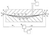
- FIG. 1is a partly schematic side elevational view of an embodiment of the hybrid leaf spring made in accordance with the method of the present invention, showing the metal primary leaf and layers of composite material positioned in a mold with a voltage source coupled to the primary leaf, thereby completing a circuit that causes the primary leaf to act as a resistance-type heater in response to an applied voltage.
- FIG. 2is a partial, cross-sectional view of the hybrid leaf spring made in accordance with the method of the present invention, showing a spring employing multiple layers of composite material.
- FIG. 3is a partly schematic, side elevational view of an embodiment of the hybrid leaf spring made in accordance with the method of the present invention showing the metal primary leaf and layers of composite material positioned in a mold and surrounded in part by an induction-type heater.
- FIG. 4is a partly schematic, side elevational view of the hybrid leaf spring made in accordance with the method of the present invention showing a mold heated via cartridge-type heaters.
- FIG. 5is a partial cross-sectional view of the hybrid leaf spring of FIG. 2 showing layers of elastomeric material between layers of composite material, and the primary leaf.
- a hybrid leaf springgenerally designated by the reference number 10 is positioned in a cavity 12 defined by a mold 14 .
- the hybrid leaf spring 10includes a primary leaf 16 with first and second layers of composite material, 18 and 20 respectively, located adjacent to a respective one of a first and second bonding surface, 22 and 24 respectively, defined by the primary leaf 16 .
- a first layer of adhesive material 26is interposed between the first layer of composite material 18 and the first bonding surface 22 and a second layer of adhesive material 28 is interposed between the second layer of composite material 20 and the second bonding surface 24 .
- the metal primary leaf 16includes opposed end sections 30 and 32 , each defining a loop or eye 34 .
- a voltage source 36is in electrical communication with the primary leaf 16 via a pair of leads 38 extending therefrom, each having an end 40 coupled to one of the eyes 34 .
- the voltage source 36is also in communication with a controller 42 , for generating command signals in accordance with temperature data stored therein.
- the voltage source 36is energized in response to commands issued from the controller 42 causing a voltage to be induced across the metal primary leaf 16 , which due to its inherent resistance, experiences an increase in temperature.
- the operation of the controller 42can be either via “open loop” control or “closed loop” control.
- open loop controla predetermined voltage input is employed to bring the spring to a known temperature.
- closed loop controla sensor (not shown) monitors the temperature of the spring and provides signals receivable by the controller 42 that in turn adjusts the voltage supplied by the voltage source 36 .
- the temperature of the primary leaf 16increases in response to commands issued from the controller to a degree sufficient to cure the first and second layers of adhesive, 26 and 28 respectively.
- the cured adhesive materialacts to bond the first and second layers of composite material, 18 and 20 respectively, to the primary leaf 16 .
- the interior cavity 12 of the mold 14can also be pressurized via pump 44 which is in gaseous communication with the mold, thereby ensuring that the layers of composite material, and the metal primary leaf are properly positioned relative to one another as the adhesive cures. While a hybrid leaf spring having a first and second layer of composite material bonded to a primary leaf has been shown and described, the present invention is not limited in this regard as a single, or multiple layers of composite material can also be employed without departing from the broader aspects of the present invention.
- a layer of adhesive material 48must be interposed between successive layers of the composite material, as well as between the primary leaf 16 and the next adjacent layer of composite material.
- the layers of adhesiveare cured in the above-described manner, however, increased curing times must be provided for in order to allow all of the adhesive material to reach curing temperature.
- an induction-type heatergenerally designated by the reference number 49 can be employed to provide thermal energy to the metal primary leaf 16 .
- the hybrid leaf spring 10positioned in the mold with the layers of adhesive material in the uncured condition, is surrounded by a coil 50 .
- An alternating current source 52is in electrical communication with the coil, providing current to the coil 50 .
- the currentin turn generates an alternating magnetic flux around the hybrid spring 10 .
- the current in the coilinduces a current in the main leaf 16 which causes an increase in thermal energy.
- the temperature of the primary leaf 16is allowed to increase to the curing temperature of the adhesive, and is held at such temperature until such time as the adhesive material is cured.
- the mold 14can be made from metal and heated via cartridge heaters 54 positioned in bores extending at least partway through the mold. Heating the mold 14 via the cartridge heaters along with simultaneously employing one of the above-described methods for heating the metal primary leaf 16 allows for attaining the adhesive cure temperature more rapidly than if only the primary leaf is heated. While cartridge heaters have been shown and described, the present invention is not limited in this regard as other methods of heating the mold known to those skilled in the pertinent art to which the invention pertains can be employed without departing from the broader aspects of the present invention. For example, hot oil can be pumped through passages defined by the mold, imparting thermal energy thereto.
- the present inventionis not limited in this regard, as the mold can be fabricated from other suitable materials known to those skilled in the art to which the invention pertains, such as, but not limited to composites, ceramics, or ceramic filled composites without departing from the broader aspects of the present invention.
- the layers of composite materialcan assume different configurations.
- the layerscan be precured and then machined to adapt to the desired contour of a finished hybrid spring, or prepreg, or wet layers can be laid up in the mold adjacent to one another, as well as to the primary leaf 16 .
- layers of adhesive positioned and cured in the above-described mannerare employed.
- layers of elastomeric material 56can be interposed between successive layers of composite material 58 , as well as between the primary leaf 16 and any adjacent layers of composite material to provide enhanced damping characteristics to the hybrid spring.
- the layers of elastomeric material 56are bonded to the layers of composite material and the metal primary leaf 16 by layers of adhesive material.
- the surfaces of the hybrid leaf spring components which contact the adhesive materialhereinafter referred to as bonding surfaces, are treated or prepared to make them more receptive to the adhesive.
- bonding surfacesPrior to assembly in the mold, the surfaces of the hybrid leaf spring components which contact the adhesive material, hereinafter referred to as bonding surfaces, are treated or prepared to make them more receptive to the adhesive.
- surface preparationcan be accomplished via sandblasting, vapor blasting, or chemical etching, with sandblasting providing the added benefit of slag removal from the metal.
- the elastomeric layerscan be surface treated by, inter alia, etching or embossing.
- Thermoset type elastomerscan also be sanded or ground, while thermoplastic material can be flame treated, corona discharge treated, inert plasma treated, and in some instances these treatments can be combined with sanding and grinding.
- the hybrid leaf spring made in accordance with the present methodit may be necessary to coat all or part of the spring with a protective coating to increase impact resistance. Alternatively, it may be necessary to coat only those areas where an adhesive layer is exposed to the outside environment.
Landscapes
- Engineering & Computer Science (AREA)
- General Engineering & Computer Science (AREA)
- Mechanical Engineering (AREA)
- Physics & Mathematics (AREA)
- Health & Medical Sciences (AREA)
- Oral & Maxillofacial Surgery (AREA)
- Thermal Sciences (AREA)
- Springs (AREA)
- Casting Or Compression Moulding Of Plastics Or The Like (AREA)
- Moulds For Moulding Plastics Or The Like (AREA)
- Laminated Bodies (AREA)
- Table Devices Or Equipment (AREA)
Abstract
Description
Claims (23)
Priority Applications (8)
| Application Number | Priority Date | Filing Date | Title |
|---|---|---|---|
| US09/490,308US6461455B1 (en) | 2000-01-24 | 2000-01-24 | Method of producing a hybrid leaf spring |
| EP01942597AEP1194292A1 (en) | 2000-01-24 | 2001-01-11 | Method for producing a hybrid leaf spring |
| PCT/US2001/000849WO2001053095A1 (en) | 2000-01-24 | 2001-01-11 | Method for producing a hybrid leaf spring |
| CA002365120ACA2365120C (en) | 2000-01-24 | 2001-01-11 | Method for producing a hybrid leaf spring |
| BR0104174-6ABR0104174A (en) | 2000-01-24 | 2001-01-11 | Method for producing a hybrid spring bundle |
| MXPA01009591AMXPA01009591A (en) | 2000-01-24 | 2001-01-11 | Method for producing a hybrid leaf spring. |
| ARP010100295AAR032302A1 (en) | 2000-01-24 | 2001-01-24 | METHOD FOR PRODUCING A BASKET OF HYBRID LEAVES |
| US10/102,100US6660114B2 (en) | 2000-01-24 | 2002-03-19 | Method for producing a hybrid leaf spring |
Applications Claiming Priority (1)
| Application Number | Priority Date | Filing Date | Title |
|---|---|---|---|
| US09/490,308US6461455B1 (en) | 2000-01-24 | 2000-01-24 | Method of producing a hybrid leaf spring |
Related Child Applications (1)
| Application Number | Title | Priority Date | Filing Date |
|---|---|---|---|
| US10/102,100Continuation-In-PartUS6660114B2 (en) | 2000-01-24 | 2002-03-19 | Method for producing a hybrid leaf spring |
Publications (1)
| Publication Number | Publication Date |
|---|---|
| US6461455B1true US6461455B1 (en) | 2002-10-08 |
Family
ID=23947499
Family Applications (1)
| Application Number | Title | Priority Date | Filing Date |
|---|---|---|---|
| US09/490,308Expired - LifetimeUS6461455B1 (en) | 2000-01-24 | 2000-01-24 | Method of producing a hybrid leaf spring |
Country Status (7)
| Country | Link |
|---|---|
| US (1) | US6461455B1 (en) |
| EP (1) | EP1194292A1 (en) |
| AR (1) | AR032302A1 (en) |
| BR (1) | BR0104174A (en) |
| CA (1) | CA2365120C (en) |
| MX (1) | MXPA01009591A (en) |
| WO (1) | WO2001053095A1 (en) |
Cited By (26)
| Publication number | Priority date | Publication date | Assignee | Title |
|---|---|---|---|---|
| US20020167121A1 (en)* | 2001-01-29 | 2002-11-14 | Visteon Global Technologies, Inc. | Composite bow mono-leaf spring |
| WO2003080338A1 (en)* | 2002-03-19 | 2003-10-02 | Pacific Coast Composites | Method for producing a hybrid leaf spring |
| US6679487B2 (en)* | 2002-03-19 | 2004-01-20 | Pacific Coast Composites | Hybrid leaf spring with reinforced bond lines |
| US20040245690A1 (en)* | 2003-02-21 | 2004-12-09 | Gerold Winkler | Hydro-mount |
| US20050051934A1 (en)* | 2003-09-05 | 2005-03-10 | Platner David K. | Attachment arrangement for a composite leaf spring which accommodates longitudinal movement through shear displacement |
| US20050051933A1 (en)* | 2003-09-05 | 2005-03-10 | Platner David K. | Composite leaf spring having an arcuate attachment arrangement for vehicle mounting |
| US20050077665A1 (en)* | 2003-09-05 | 2005-04-14 | Platner David K. | Composite leaf spring geometry with an interlocking interface |
| US20050172670A1 (en)* | 2003-02-07 | 2005-08-11 | Hoya Corporation | Method of manufacturing a glass substrate for a magnetic disk and method of manufacturing a magnetic disk |
| US20120267835A1 (en)* | 2009-12-15 | 2012-10-25 | Benteler Sgl Gmbh & Co. Kg | Leaf spring arrangement |
| US20130074341A1 (en)* | 2011-09-28 | 2013-03-28 | Hitachi Automotive Systems, Ltd. | Method of manufacturing cylinder apparatus |
| US20140373655A1 (en)* | 2012-01-31 | 2014-12-25 | Mitsubishi Steel MFG CO., LTD | Spring unit and slide mechanism |
| US20150316114A1 (en)* | 2010-02-26 | 2015-11-05 | Ifc Composite Gmbh | Leaf spring made of a fiber composite material having integrated bearing eyes and method of producing said leaf spring |
| US9597938B2 (en) | 2013-03-15 | 2017-03-21 | Polyone Corporation | High strength, light weight composite leaf spring and method of making |
| US9657799B2 (en) | 2013-03-15 | 2017-05-23 | Polyone Corporation | Suspension sub-assembly |
| US20170313149A1 (en)* | 2014-11-19 | 2017-11-02 | Nhk Spring Co., Ltd. | Leaf spring device and method for manufacturing leaf spring device |
| US10046485B2 (en) | 2012-08-27 | 2018-08-14 | Ifc Composite Gmbh | Method for simultaneous production of a plurality of leaf springs from a fiber composite material |
| US10118342B2 (en)* | 2013-04-03 | 2018-11-06 | Arianegroup Sas | Welded structural joint between a high-performance thermoplastic matrix composite material and an elastomer by powder functionalization |
| US10131093B2 (en)* | 2013-04-03 | 2018-11-20 | Arianegroup Sas | Welded structural joint between a high-performance thermoplastic matrix composite material and an elastomer |
| WO2019101470A1 (en)* | 2017-11-23 | 2019-05-31 | Zf Friedrichshafen Ag | Method of producing a chassis component, and chassis component |
| US20190309814A1 (en)* | 2018-04-06 | 2019-10-10 | Zf Friedrichshafen Ag | Leaf spring device for a vehicle and method for producing such a leaf spring device |
| US10703394B2 (en)* | 2015-09-10 | 2020-07-07 | Kawasaki Jukogyo Kabushiki Kaisha | Method of producing electrode-equipped plate spring of railcar bogie |
| US11168756B2 (en)* | 2015-04-15 | 2021-11-09 | Pumpkin Mounts, Llc | Mounting |
| US20210356010A1 (en)* | 2018-10-17 | 2021-11-18 | Automotive Insight, Llc | Composite leaf spring and method of manufacture |
| CN114131940A (en)* | 2021-11-23 | 2022-03-04 | 中国直升机设计研究所 | Method and device for gluing, pressurizing and curing fluororubber plate |
| US11453263B2 (en)* | 2020-12-07 | 2022-09-27 | Hyundai Motor Company | Composite material spring for suspension device of vehicle, and method for controlling driving of vehicle using the same |
| US11597057B2 (en) | 2019-02-01 | 2023-03-07 | Trelleborg Sealing Solutions Germany Gmbh | Impact forming of thermoplastic composites |
Families Citing this family (1)
| Publication number | Priority date | Publication date | Assignee | Title |
|---|---|---|---|---|
| CN107606014B (en)* | 2017-09-17 | 2019-11-26 | 刘守银 | A kind of leaf spring and its manufacturing process |
Citations (51)
| Publication number | Priority date | Publication date | Assignee | Title |
|---|---|---|---|---|
| US1922781A (en) | 1931-05-26 | 1933-08-15 | Joseph F Rogers | Auxiliary spring for motor cars |
| US2175231A (en)* | 1938-02-17 | 1939-10-10 | Cleveland Graphite Bronze Co | Spring liner construction |
| US2188689A (en) | 1937-05-28 | 1940-01-30 | Laher Spring & Tire Corp | Vehicle spring |
| US2667347A (en) | 1950-10-25 | 1954-01-26 | Jacobs Co F L | Combined liner and cover for leaf springs |
| US2698750A (en) | 1952-04-28 | 1955-01-04 | Nicosia Chris | Rust-proofed automobile spring |
| US2861798A (en) | 1955-03-28 | 1958-11-25 | Lenet Sidney | Vehicle spring |
| US2969230A (en) | 1959-02-04 | 1961-01-24 | Moog Industries Inc | Vehicle spring device |
| US3204944A (en) | 1963-03-26 | 1965-09-07 | Rockwell Standard Co | Tapered springs and methods of manufacturing same |
| US3586307A (en) | 1969-06-25 | 1971-06-22 | North American Rockwell | Composite spring assembly |
| US3698702A (en) | 1971-03-05 | 1972-10-17 | Lord Corp | Composite leaf spring |
| US3960069A (en)* | 1974-03-21 | 1976-06-01 | Formica Corporation | Method and apparatus for controlling a press |
| JPS53127958A (en) | 1977-04-14 | 1978-11-08 | Toray Ind Inc | Coil spring made of fiber reinforced plastics |
| US4126759A (en)* | 1975-06-30 | 1978-11-21 | Raychem Corporation | Coupling means |
| JPS5422048A (en) | 1977-07-20 | 1979-02-19 | Toray Ind Inc | Leaf spring |
| JPS5425986A (en) | 1977-07-29 | 1979-02-27 | Toray Ind Inc | Leaf spring of fiber reinforced plastic |
| JPS5474058A (en) | 1977-11-25 | 1979-06-13 | Toray Ind Inc | Compound leaf spring of metal-fiber reinforced resin |
| JPS5474057A (en) | 1977-11-24 | 1979-06-13 | Toray Ind Inc | Fiber reinforced resin leaf spring |
| JPS5479343A (en) | 1977-12-06 | 1979-06-25 | Toray Ind Inc | Flat spring in fiber reinforcing resin |
| JPS54141852A (en) | 1978-04-27 | 1979-11-05 | Nhk Spring Co Ltd | Manufacture of frp leaf spring |
| JPS54141944A (en) | 1978-04-27 | 1979-11-05 | Nhk Spring Co Ltd | Frp leaf spring |
| JPS5527522A (en) | 1978-08-16 | 1980-02-27 | Toyota Motor Corp | Construction of composite plate-spring for vehicle |
| JPS5536644A (en) | 1978-09-06 | 1980-03-14 | Nhk Spring Co Ltd | Vehicle suspending laminated spring |
| JPS5586934A (en) | 1978-12-25 | 1980-07-01 | Nhk Spring Co Ltd | Frp leaf spring |
| JPS5586935A (en) | 1978-12-25 | 1980-07-01 | Nhk Spring Co Ltd | Frp leaf spring |
| JPS5587606A (en) | 1978-12-23 | 1980-07-02 | Nhk Spring Co Ltd | Clamping device for lamellar spring |
| JPS55107138A (en) | 1979-02-09 | 1980-08-16 | Kawaju Shatai Kogyo Kk | Combined spring for supporting axle |
| JPS5694041A (en) | 1979-12-27 | 1981-07-30 | Nhk Spring Co Ltd | Spring device made of frp board |
| JPS56120835A (en) | 1980-02-27 | 1981-09-22 | Nhk Spring Co Ltd | Lap leaf spring device |
| JPS5743035A (en) | 1980-08-27 | 1982-03-10 | Nhk Spring Co Ltd | Frp spring plate |
| JPS5743036A (en) | 1980-08-27 | 1982-03-10 | Nhk Spring Co Ltd | Frp spring plate |
| JPS57101140A (en) | 1980-12-15 | 1982-06-23 | Nhk Spring Co Ltd | Frp leaf spring device |
| DE3236330A1 (en) | 1981-11-03 | 1983-05-11 | Steyr-Daimler-Puch AG, 1010 Wien | Leaf spring, particularly for vehicle axle suspension |
| US4411159A (en)* | 1980-07-12 | 1983-10-25 | Rubery Owen Group Services Limited | A fibre reinforced resin composite leaf spring for determining the magnitude of a load |
| GB2125514A (en) | 1982-08-20 | 1984-03-07 | Budd Co | Fibre reinforced plastics leaf spring |
| JPS5989843A (en) | 1982-11-12 | 1984-05-24 | Toyota Motor Corp | Compression coil spring and method of its manufacture |
| US4508325A (en) | 1982-04-21 | 1985-04-02 | Gkn Technology Limited | Composite leaf springs |
| US4507907A (en)* | 1981-09-02 | 1985-04-02 | Burr-Brown Corporation | Expendable heater sealing process |
| US4541891A (en)* | 1982-09-30 | 1985-09-17 | William C. Heller, Jr. | Method and apparatus for heat sealing plastic members |
| JPS60220233A (en) | 1984-04-17 | 1985-11-02 | Nhk Spring Co Ltd | Frp leaf spring device |
| EP0162191A1 (en) | 1984-04-30 | 1985-11-27 | Hoesch Aktiengesellschaft | Leaf spring, in particular for the spring suspension of vehicles |
| US4557500A (en) | 1981-11-18 | 1985-12-10 | Bertin & Cie | Suspension for a motor vehicle by means of an elastic blade |
| US4565356A (en) | 1983-10-13 | 1986-01-21 | A. O. Smith Corporation | Bushing construction for a fiber reinforced plastic leaf spring |
| US4575057A (en) | 1983-12-27 | 1986-03-11 | Ford Motor Company | Filament wound composite material leaf spring |
| JPS6220926A (en) | 1985-07-19 | 1987-01-29 | Nhk Spring Co Ltd | Compound laminated spring device |
| US4683016A (en)* | 1985-09-03 | 1987-07-28 | Sun Coast Plastics, Inc. | Process for forming a two part closure |
| US4688778A (en)* | 1982-10-01 | 1987-08-25 | Isosport Verbundbauteile Ges.M.B.H. | Plastic leaf spring |
| FR2601905A1 (en) | 1986-07-25 | 1988-01-29 | Renault | Suspension with elastic leaves for a motor vehicle |
| US5087503A (en) | 1989-09-14 | 1992-02-11 | Pacific Coast Composites, Inc. | Composite constant stress beam with gradient fiber distribution |
| US5225008A (en) | 1991-11-18 | 1993-07-06 | Nhk Spring Co., Ltd. | Method for manufacturing a high-strength spring |
| US5258082A (en) | 1991-11-18 | 1993-11-02 | Nhk Spring Co., Ltd. | High strength spring |
| US6012709A (en)* | 1997-08-06 | 2000-01-11 | Pacific Coast Composites | Hybrid leaf spring and suspension system for supporting an axle on a vehicle |
- 2000
- 2000-01-24USUS09/490,308patent/US6461455B1/ennot_activeExpired - Lifetime
- 2001
- 2001-01-11EPEP01942597Apatent/EP1194292A1/ennot_activeWithdrawn
- 2001-01-11MXMXPA01009591Apatent/MXPA01009591A/enunknown
- 2001-01-11BRBR0104174-6Apatent/BR0104174A/ennot_activeIP Right Cessation
- 2001-01-11CACA002365120Apatent/CA2365120C/ennot_activeExpired - Fee Related
- 2001-01-11WOPCT/US2001/000849patent/WO2001053095A1/ennot_activeApplication Discontinuation
- 2001-01-24ARARP010100295Apatent/AR032302A1/enunknown
Patent Citations (53)
| Publication number | Priority date | Publication date | Assignee | Title |
|---|---|---|---|---|
| US1922781A (en) | 1931-05-26 | 1933-08-15 | Joseph F Rogers | Auxiliary spring for motor cars |
| US2188689A (en) | 1937-05-28 | 1940-01-30 | Laher Spring & Tire Corp | Vehicle spring |
| US2175231A (en)* | 1938-02-17 | 1939-10-10 | Cleveland Graphite Bronze Co | Spring liner construction |
| US2667347A (en) | 1950-10-25 | 1954-01-26 | Jacobs Co F L | Combined liner and cover for leaf springs |
| US2698750A (en) | 1952-04-28 | 1955-01-04 | Nicosia Chris | Rust-proofed automobile spring |
| US2861798A (en) | 1955-03-28 | 1958-11-25 | Lenet Sidney | Vehicle spring |
| US2969230A (en) | 1959-02-04 | 1961-01-24 | Moog Industries Inc | Vehicle spring device |
| US3204944A (en) | 1963-03-26 | 1965-09-07 | Rockwell Standard Co | Tapered springs and methods of manufacturing same |
| US3586307A (en) | 1969-06-25 | 1971-06-22 | North American Rockwell | Composite spring assembly |
| US3698702A (en) | 1971-03-05 | 1972-10-17 | Lord Corp | Composite leaf spring |
| US3960069A (en)* | 1974-03-21 | 1976-06-01 | Formica Corporation | Method and apparatus for controlling a press |
| US4126759A (en)* | 1975-06-30 | 1978-11-21 | Raychem Corporation | Coupling means |
| JPS53127958A (en) | 1977-04-14 | 1978-11-08 | Toray Ind Inc | Coil spring made of fiber reinforced plastics |
| JPS5422048A (en) | 1977-07-20 | 1979-02-19 | Toray Ind Inc | Leaf spring |
| JPS5425986A (en) | 1977-07-29 | 1979-02-27 | Toray Ind Inc | Leaf spring of fiber reinforced plastic |
| JPS5474057A (en) | 1977-11-24 | 1979-06-13 | Toray Ind Inc | Fiber reinforced resin leaf spring |
| JPS5474058A (en) | 1977-11-25 | 1979-06-13 | Toray Ind Inc | Compound leaf spring of metal-fiber reinforced resin |
| JPS5479343A (en) | 1977-12-06 | 1979-06-25 | Toray Ind Inc | Flat spring in fiber reinforcing resin |
| JPS54141852A (en) | 1978-04-27 | 1979-11-05 | Nhk Spring Co Ltd | Manufacture of frp leaf spring |
| JPS54141944A (en) | 1978-04-27 | 1979-11-05 | Nhk Spring Co Ltd | Frp leaf spring |
| JPS5527522A (en) | 1978-08-16 | 1980-02-27 | Toyota Motor Corp | Construction of composite plate-spring for vehicle |
| JPS5536644A (en) | 1978-09-06 | 1980-03-14 | Nhk Spring Co Ltd | Vehicle suspending laminated spring |
| JPS5587606A (en) | 1978-12-23 | 1980-07-02 | Nhk Spring Co Ltd | Clamping device for lamellar spring |
| JPS5586934A (en) | 1978-12-25 | 1980-07-01 | Nhk Spring Co Ltd | Frp leaf spring |
| JPS5586935A (en) | 1978-12-25 | 1980-07-01 | Nhk Spring Co Ltd | Frp leaf spring |
| JPS55107138A (en) | 1979-02-09 | 1980-08-16 | Kawaju Shatai Kogyo Kk | Combined spring for supporting axle |
| JPS5694041A (en) | 1979-12-27 | 1981-07-30 | Nhk Spring Co Ltd | Spring device made of frp board |
| JPS56120835A (en) | 1980-02-27 | 1981-09-22 | Nhk Spring Co Ltd | Lap leaf spring device |
| US4411159A (en)* | 1980-07-12 | 1983-10-25 | Rubery Owen Group Services Limited | A fibre reinforced resin composite leaf spring for determining the magnitude of a load |
| JPS5743035A (en) | 1980-08-27 | 1982-03-10 | Nhk Spring Co Ltd | Frp spring plate |
| JPS5743036A (en) | 1980-08-27 | 1982-03-10 | Nhk Spring Co Ltd | Frp spring plate |
| JPS57101140A (en) | 1980-12-15 | 1982-06-23 | Nhk Spring Co Ltd | Frp leaf spring device |
| US4507907A (en)* | 1981-09-02 | 1985-04-02 | Burr-Brown Corporation | Expendable heater sealing process |
| DE3236330A1 (en) | 1981-11-03 | 1983-05-11 | Steyr-Daimler-Puch AG, 1010 Wien | Leaf spring, particularly for vehicle axle suspension |
| US4557500A (en) | 1981-11-18 | 1985-12-10 | Bertin & Cie | Suspension for a motor vehicle by means of an elastic blade |
| US4508325A (en) | 1982-04-21 | 1985-04-02 | Gkn Technology Limited | Composite leaf springs |
| GB2125514A (en) | 1982-08-20 | 1984-03-07 | Budd Co | Fibre reinforced plastics leaf spring |
| US4519591A (en) | 1982-08-20 | 1985-05-28 | Bush John W | Non-metallic leaf spring structure |
| US4541891A (en)* | 1982-09-30 | 1985-09-17 | William C. Heller, Jr. | Method and apparatus for heat sealing plastic members |
| US4688778A (en)* | 1982-10-01 | 1987-08-25 | Isosport Verbundbauteile Ges.M.B.H. | Plastic leaf spring |
| US4747898A (en)* | 1982-10-01 | 1988-05-31 | Isovolta Osterreichische Isolierstoffwerke Aktiengesellschaft | Method of making a plastic leaf spring |
| JPS5989843A (en) | 1982-11-12 | 1984-05-24 | Toyota Motor Corp | Compression coil spring and method of its manufacture |
| US4565356A (en) | 1983-10-13 | 1986-01-21 | A. O. Smith Corporation | Bushing construction for a fiber reinforced plastic leaf spring |
| US4575057A (en) | 1983-12-27 | 1986-03-11 | Ford Motor Company | Filament wound composite material leaf spring |
| JPS60220233A (en) | 1984-04-17 | 1985-11-02 | Nhk Spring Co Ltd | Frp leaf spring device |
| EP0162191A1 (en) | 1984-04-30 | 1985-11-27 | Hoesch Aktiengesellschaft | Leaf spring, in particular for the spring suspension of vehicles |
| JPS6220926A (en) | 1985-07-19 | 1987-01-29 | Nhk Spring Co Ltd | Compound laminated spring device |
| US4683016A (en)* | 1985-09-03 | 1987-07-28 | Sun Coast Plastics, Inc. | Process for forming a two part closure |
| FR2601905A1 (en) | 1986-07-25 | 1988-01-29 | Renault | Suspension with elastic leaves for a motor vehicle |
| US5087503A (en) | 1989-09-14 | 1992-02-11 | Pacific Coast Composites, Inc. | Composite constant stress beam with gradient fiber distribution |
| US5225008A (en) | 1991-11-18 | 1993-07-06 | Nhk Spring Co., Ltd. | Method for manufacturing a high-strength spring |
| US5258082A (en) | 1991-11-18 | 1993-11-02 | Nhk Spring Co., Ltd. | High strength spring |
| US6012709A (en)* | 1997-08-06 | 2000-01-11 | Pacific Coast Composites | Hybrid leaf spring and suspension system for supporting an axle on a vehicle |
Cited By (37)
| Publication number | Priority date | Publication date | Assignee | Title |
|---|---|---|---|---|
| US6660114B2 (en) | 2000-01-24 | 2003-12-09 | Pacific Coast Composites | Method for producing a hybrid leaf spring |
| US20020167121A1 (en)* | 2001-01-29 | 2002-11-14 | Visteon Global Technologies, Inc. | Composite bow mono-leaf spring |
| WO2003080338A1 (en)* | 2002-03-19 | 2003-10-02 | Pacific Coast Composites | Method for producing a hybrid leaf spring |
| US6679487B2 (en)* | 2002-03-19 | 2004-01-20 | Pacific Coast Composites | Hybrid leaf spring with reinforced bond lines |
| WO2003081076A3 (en)* | 2002-03-19 | 2004-03-25 | Pacific Coast Composites | Hybrid leaf spring with reinforced bond lines |
| US20050172670A1 (en)* | 2003-02-07 | 2005-08-11 | Hoya Corporation | Method of manufacturing a glass substrate for a magnetic disk and method of manufacturing a magnetic disk |
| US20040245690A1 (en)* | 2003-02-21 | 2004-12-09 | Gerold Winkler | Hydro-mount |
| US20050077665A1 (en)* | 2003-09-05 | 2005-04-14 | Platner David K. | Composite leaf spring geometry with an interlocking interface |
| US20050051933A1 (en)* | 2003-09-05 | 2005-03-10 | Platner David K. | Composite leaf spring having an arcuate attachment arrangement for vehicle mounting |
| US6991223B2 (en) | 2003-09-05 | 2006-01-31 | Arvinmeritor Technology Llc | Composite leaf spring having an arcuate attachment arrangement for vehicle mounting |
| US7017888B2 (en) | 2003-09-05 | 2006-03-28 | Arvinmeritor Technology Llc | Attachment arrangement for a composite leaf spring which accommodates longitudinal movement through shear displacement |
| US7419146B2 (en) | 2003-09-05 | 2008-09-02 | Arvinemeritor Technology, Llc | Composite leaf spring geometry with an interlocking interface |
| US20050051934A1 (en)* | 2003-09-05 | 2005-03-10 | Platner David K. | Attachment arrangement for a composite leaf spring which accommodates longitudinal movement through shear displacement |
| US20120267835A1 (en)* | 2009-12-15 | 2012-10-25 | Benteler Sgl Gmbh & Co. Kg | Leaf spring arrangement |
| US8925909B2 (en)* | 2009-12-15 | 2015-01-06 | Benteler Sgl Gmbh & Co. Kg | Leaf spring arrangement |
| US20150316114A1 (en)* | 2010-02-26 | 2015-11-05 | Ifc Composite Gmbh | Leaf spring made of a fiber composite material having integrated bearing eyes and method of producing said leaf spring |
| US9746046B2 (en)* | 2010-02-26 | 2017-08-29 | Ifc Composite Gmbh | Leaf spring made of a fiber composite material having integrated bearing eyes and method of producing said leaf spring |
| US9309947B2 (en)* | 2011-09-28 | 2016-04-12 | Hitachi Automotive Systems, Ltd. | Method of manufacturing cylinder apparatus |
| US20130074341A1 (en)* | 2011-09-28 | 2013-03-28 | Hitachi Automotive Systems, Ltd. | Method of manufacturing cylinder apparatus |
| US9316280B2 (en)* | 2012-01-31 | 2016-04-19 | Mitsubishi Steel Mfg. Co., Ltd. | Spring unit and slide mechanism |
| US20140373655A1 (en)* | 2012-01-31 | 2014-12-25 | Mitsubishi Steel MFG CO., LTD | Spring unit and slide mechanism |
| US10046485B2 (en) | 2012-08-27 | 2018-08-14 | Ifc Composite Gmbh | Method for simultaneous production of a plurality of leaf springs from a fiber composite material |
| US9597938B2 (en) | 2013-03-15 | 2017-03-21 | Polyone Corporation | High strength, light weight composite leaf spring and method of making |
| US9657799B2 (en) | 2013-03-15 | 2017-05-23 | Polyone Corporation | Suspension sub-assembly |
| US10131093B2 (en)* | 2013-04-03 | 2018-11-20 | Arianegroup Sas | Welded structural joint between a high-performance thermoplastic matrix composite material and an elastomer |
| US10118342B2 (en)* | 2013-04-03 | 2018-11-06 | Arianegroup Sas | Welded structural joint between a high-performance thermoplastic matrix composite material and an elastomer by powder functionalization |
| US20170313149A1 (en)* | 2014-11-19 | 2017-11-02 | Nhk Spring Co., Ltd. | Leaf spring device and method for manufacturing leaf spring device |
| US10549594B2 (en)* | 2014-11-19 | 2020-02-04 | Nhk Spring Co., Ltd. | Leaf spring device and method for manufacturing leaf spring device |
| US11168756B2 (en)* | 2015-04-15 | 2021-11-09 | Pumpkin Mounts, Llc | Mounting |
| US10703394B2 (en)* | 2015-09-10 | 2020-07-07 | Kawasaki Jukogyo Kabushiki Kaisha | Method of producing electrode-equipped plate spring of railcar bogie |
| WO2019101470A1 (en)* | 2017-11-23 | 2019-05-31 | Zf Friedrichshafen Ag | Method of producing a chassis component, and chassis component |
| US20190309814A1 (en)* | 2018-04-06 | 2019-10-10 | Zf Friedrichshafen Ag | Leaf spring device for a vehicle and method for producing such a leaf spring device |
| US20210356010A1 (en)* | 2018-10-17 | 2021-11-18 | Automotive Insight, Llc | Composite leaf spring and method of manufacture |
| US11933381B2 (en)* | 2018-10-17 | 2024-03-19 | Automotive Insight, Llc | Composite leaf spring and method of manufacture |
| US11597057B2 (en) | 2019-02-01 | 2023-03-07 | Trelleborg Sealing Solutions Germany Gmbh | Impact forming of thermoplastic composites |
| US11453263B2 (en)* | 2020-12-07 | 2022-09-27 | Hyundai Motor Company | Composite material spring for suspension device of vehicle, and method for controlling driving of vehicle using the same |
| CN114131940A (en)* | 2021-11-23 | 2022-03-04 | 中国直升机设计研究所 | Method and device for gluing, pressurizing and curing fluororubber plate |
Also Published As
| Publication number | Publication date |
|---|---|
| CA2365120A1 (en) | 2001-07-26 |
| CA2365120C (en) | 2005-12-27 |
| BR0104174A (en) | 2001-12-18 |
| WO2001053095A1 (en) | 2001-07-26 |
| MXPA01009591A (en) | 2003-07-21 |
| AR032302A1 (en) | 2003-11-05 |
| EP1194292A1 (en) | 2002-04-10 |
Similar Documents
| Publication | Publication Date | Title |
|---|---|---|
| US6461455B1 (en) | Method of producing a hybrid leaf spring | |
| US6660114B2 (en) | Method for producing a hybrid leaf spring | |
| CN105358860B (en) | High-strength light-weight composite material leaf spring and manufacturing method thereof | |
| US6012709A (en) | Hybrid leaf spring and suspension system for supporting an axle on a vehicle | |
| Shankar et al. | Mono composite leaf spring for light weight vehicle–design, end joint analysis and testing | |
| US20150343875A1 (en) | Suspension sub-assembly | |
| US6679487B2 (en) | Hybrid leaf spring with reinforced bond lines | |
| US20140284856A1 (en) | Light weight composite leaf spring and method of making | |
| EP1182243B1 (en) | Method for bonding non-magnetic members | |
| CN107000523A (en) | Chassis and the method for manufacturing chassis | |
| JP2002122169A (en) | Composite plate spring having improved lateral rigidity | |
| US6435485B1 (en) | Composite bow mono-leaf spring | |
| EP0391551B1 (en) | Composite weld gun and method of making same | |
| EP3180204A1 (en) | Suspension sub-assembly | |
| AU2017294152A1 (en) | A structural member | |
| CA3122901C (en) | Leaf spring, manufacturing process and mould of that leaf spring | |
| JPH03248832A (en) | Joining method of fiber-reinforced composite | |
| WOOTTON et al. | Structural Automotive Components in Fibre | |
| Babu et al. | INTERNATIONAL JOURNAL OF ENGINEERING SCIENCES & RESEARCH TECHNOLOGY Design and Analysis of Leaf Spring with Composite materials | |
| MXPA00001298A (en) | Hybrid leaf spring and suspension system for supporting an axle on a vehicle |
Legal Events
| Date | Code | Title | Description |
|---|---|---|---|
| AS | Assignment | Owner name:PACIFIC COAST COMPOSITES, COLORADO Free format text:ASSIGNMENT OF ASSIGNORS INTEREST;ASSIGNORS:MEATTO, FRANK;PILPEL, EDWARD;GORDON, D. MICHAEL;AND OTHERS;REEL/FRAME:010849/0247 Effective date:20000505 | |
| STCF | Information on status: patent grant | Free format text:PATENTED CASE | |
| AS | Assignment | Owner name:GORDON COMPOSITES, INC., COLORADO Free format text:ASSIGNMENT OF ASSIGNORS INTEREST;ASSIGNOR:PACIFIC COAST COMPOSITES;REEL/FRAME:016610/0278 Effective date:20050915 | |
| FPAY | Fee payment | Year of fee payment:4 | |
| FPAY | Fee payment | Year of fee payment:8 | |
| FPAY | Fee payment | Year of fee payment:12 | |
| AS | Assignment | Owner name:GORDON HOLDINGS, INC., COLORADO Free format text:ASSIGNMENT OF ASSIGNORS INTEREST;ASSIGNOR:GORDON COMPOSITES, INC.;REEL/FRAME:040116/0519 Effective date:20140101 | |
| AS | Assignment | Owner name:POLYONE CORPORATION, OHIO Free format text:ASSIGNMENT OF ASSIGNORS INTEREST;ASSIGNOR:GORDON HOLDINGS, INC.;REEL/FRAME:040304/0106 Effective date:20160726 | |
| FEPP | Fee payment procedure | Free format text:ENTITY STATUS SET TO UNDISCOUNTED (ORIGINAL EVENT CODE: BIG.); ENTITY STATUS OF PATENT OWNER: LARGE ENTITY |