US6461335B1 - Tube dependent anti-free-flow valve - Google Patents
Tube dependent anti-free-flow valveDownload PDFInfo
- Publication number
- US6461335B1 US6461335B1US09/514,667US51466700AUS6461335B1US 6461335 B1US6461335 B1US 6461335B1US 51466700 AUS51466700 AUS 51466700AUS 6461335 B1US6461335 B1US 6461335B1
- Authority
- US
- United States
- Prior art keywords
- tube assembly
- tube
- lumen
- slit
- fluid
- Prior art date
- Legal status (The legal status is an assumption and is not a legal conclusion. Google has not performed a legal analysis and makes no representation as to the accuracy of the status listed.)
- Expired - Lifetime
Links
- 230000001419dependent effectEffects0.000titledescription2
- 239000012530fluidSubstances0.000claimsabstractdescription110
- 230000007423decreaseEffects0.000claimsabstractdescription10
- 230000008878couplingEffects0.000claimsdescription10
- 238000010168coupling processMethods0.000claimsdescription10
- 238000005859coupling reactionMethods0.000claimsdescription10
- 238000000034methodMethods0.000claimsdescription8
- 230000003247decreasing effectEffects0.000claimsdescription6
- 239000000463materialSubstances0.000claims3
- 238000007789sealingMethods0.000claims1
- 230000002572peristaltic effectEffects0.000description7
- 238000004519manufacturing processMethods0.000description3
- 238000004891communicationMethods0.000description2
- 230000005484gravityEffects0.000description2
- 230000037361pathwayEffects0.000description2
- 210000001835visceraAnatomy0.000description2
- 230000009471actionEffects0.000description1
- 239000012190activatorSubstances0.000description1
- 230000007812deficiencyEffects0.000description1
- 239000003814drugSubstances0.000description1
- 230000002496gastric effectEffects0.000description1
- 238000001802infusionMethods0.000description1
- 230000002452interceptive effectEffects0.000description1
- 238000001990intravenous administrationMethods0.000description1
- 230000014759maintenance of locationEffects0.000description1
- 238000012986modificationMethods0.000description1
- 230000004048modificationEffects0.000description1
- 230000009279non-visceral effectEffects0.000description1
- 230000035764nutritionEffects0.000description1
- 235000016709nutritionNutrition0.000description1
- 230000000717retained effectEffects0.000description1
Images


Classifications
- A—HUMAN NECESSITIES
- A61—MEDICAL OR VETERINARY SCIENCE; HYGIENE
- A61M—DEVICES FOR INTRODUCING MEDIA INTO, OR ONTO, THE BODY; DEVICES FOR TRANSDUCING BODY MEDIA OR FOR TAKING MEDIA FROM THE BODY; DEVICES FOR PRODUCING OR ENDING SLEEP OR STUPOR
- A61M5/00—Devices for bringing media into the body in a subcutaneous, intra-vascular or intramuscular way; Accessories therefor, e.g. filling or cleaning devices, arm-rests
- A61M5/14—Infusion devices, e.g. infusing by gravity; Blood infusion; Accessories therefor
- A61M5/168—Means for controlling media flow to the body or for metering media to the body, e.g. drip meters, counters ; Monitoring media flow to the body
- A—HUMAN NECESSITIES
- A61—MEDICAL OR VETERINARY SCIENCE; HYGIENE
- A61M—DEVICES FOR INTRODUCING MEDIA INTO, OR ONTO, THE BODY; DEVICES FOR TRANSDUCING BODY MEDIA OR FOR TAKING MEDIA FROM THE BODY; DEVICES FOR PRODUCING OR ENDING SLEEP OR STUPOR
- A61M39/00—Tubes, tube connectors, tube couplings, valves, access sites or the like, specially adapted for medical use
- A61M39/22—Valves or arrangement of valves
- A61M39/24—Check- or non-return valves
- A—HUMAN NECESSITIES
- A61—MEDICAL OR VETERINARY SCIENCE; HYGIENE
- A61M—DEVICES FOR INTRODUCING MEDIA INTO, OR ONTO, THE BODY; DEVICES FOR TRANSDUCING BODY MEDIA OR FOR TAKING MEDIA FROM THE BODY; DEVICES FOR PRODUCING OR ENDING SLEEP OR STUPOR
- A61M5/00—Devices for bringing media into the body in a subcutaneous, intra-vascular or intramuscular way; Accessories therefor, e.g. filling or cleaning devices, arm-rests
- A61M5/14—Infusion devices, e.g. infusing by gravity; Blood infusion; Accessories therefor
- A—HUMAN NECESSITIES
- A61—MEDICAL OR VETERINARY SCIENCE; HYGIENE
- A61M—DEVICES FOR INTRODUCING MEDIA INTO, OR ONTO, THE BODY; DEVICES FOR TRANSDUCING BODY MEDIA OR FOR TAKING MEDIA FROM THE BODY; DEVICES FOR PRODUCING OR ENDING SLEEP OR STUPOR
- A61M39/00—Tubes, tube connectors, tube couplings, valves, access sites or the like, specially adapted for medical use
- A61M39/22—Valves or arrangement of valves
- A61M39/24—Check- or non-return valves
- A61M2039/2426—Slit valve
- A—HUMAN NECESSITIES
- A61—MEDICAL OR VETERINARY SCIENCE; HYGIENE
- A61M—DEVICES FOR INTRODUCING MEDIA INTO, OR ONTO, THE BODY; DEVICES FOR TRANSDUCING BODY MEDIA OR FOR TAKING MEDIA FROM THE BODY; DEVICES FOR PRODUCING OR ENDING SLEEP OR STUPOR
- A61M39/00—Tubes, tube connectors, tube couplings, valves, access sites or the like, specially adapted for medical use
- A61M39/22—Valves or arrangement of valves
- A61M39/26—Valves closing automatically on disconnecting the line and opening on reconnection thereof
- A—HUMAN NECESSITIES
- A61—MEDICAL OR VETERINARY SCIENCE; HYGIENE
- A61M—DEVICES FOR INTRODUCING MEDIA INTO, OR ONTO, THE BODY; DEVICES FOR TRANSDUCING BODY MEDIA OR FOR TAKING MEDIA FROM THE BODY; DEVICES FOR PRODUCING OR ENDING SLEEP OR STUPOR
- A61M5/00—Devices for bringing media into the body in a subcutaneous, intra-vascular or intramuscular way; Accessories therefor, e.g. filling or cleaning devices, arm-rests
- A61M5/14—Infusion devices, e.g. infusing by gravity; Blood infusion; Accessories therefor
- A61M5/142—Pressure infusion, e.g. using pumps
- A61M5/14212—Pumping with an aspiration and an expulsion action
- A61M5/14232—Roller pumps
Definitions
- the present inventionrelates to a device for preventing fluid free flow in a fluid administration system, and more particularly to an anti-free flow valve device disposed within a lumen of a tube assembly. More specifically, the present invention relates to a tube diameter dependent anti-free-flow valve device that prevents fluid free flow when the tube assembly is in a relaxed condition, while permitting uninhibited fluid flow when the tube assembly is in a stretched condition.
- Administering fluid containing medicine or nutrition to a patientis generally well-known in the art.
- fluidis supplied to a patient by a tube assembly which provides a fluid pathway between a fluid source and a patient.
- the fluidis supplied to the patient through the tube assembly by either an enteral connection which accesses a visceral organ (gastrointestinal feeding) of a patient or through a parenteral connection which accesses a non-visceral organ (intravenous feeding).
- Fluid flow rate through the tube assemblymay be manually controlled by a mechanical clip which is designed to progressively occlude the tube assembly and selectively impede fluid flow induced by the force of gravity.
- a mechanical clip which operates to occlude a portion of the tube assemblyis a conventional roller clamp that has a hollow body with opposed outlets and a pair of angled slots formed opposite of one another transverse to the outlets.
- the clipfurther includes a wheel having an axle which is coupled to the body through the slots. A portion of the tube assembly is then inserted through both the outlets and the wheel axially advanced along the slots to pinch a portion of the tube against the body which progressively occludes the tube assembly.
- the mechanical clipoperates to provide a cost-efficient method for controlling fluid flow rate, the clip must be manually actuated by the user. Further, the wheel of the mechanical clip can be inadvertently bumped or jostled out of position resulting in an inappropriate flow rate.
- calibrated pumpsIn order to better enhance fluid flow rate control in a fluid administration system, calibrated pumps have been utilized.
- One such calibrated pumpis a peristaltic pump connected in-line along a portion of the tube assembly between the fluid source and the patient.
- the peristaltic pumpadvances the fluid through the tube assembly by progressively occluding successive portions of the tube assembly and urging each occluded portion forward.
- mechanical clipsare typically not employed or are disengaged to prevent the clip from interfering with the operation of the pump.
- peristaltic pumpshave substantially advanced the art, further improvements are required. For example, once the tube assembly is disengaged from the pump fluid flow rate through the tube assembly becomes unrestrained as fluid is drawn through the tube assembly due to the force of gravity. This situation is known as fluid free flow and may present an undesirable, or even life-threatening situation, if left undetected because of the risk of overfeeding or overmedicating a patient.
- the clampincludes a V-shaped channel which is spring biased into a closed position where the narrow portion of the V-shaped channel is sized to substantially crimp, or occlude, a portion of the tube assembly and prevent fluid free flow therethrough.
- the clampis placed in an open position by a handle which overlays the pump and depresses the springs such that the tube assembly is positioned within the wider portion of the V-shaped channel to permit unrestricted flow through the tube assembly when the pump is operating.
- the handleis released, the V-shaped portion will automatically slide into the closed position and prevent fluid free flow by occluding a portion of the tube assembly.
- the present inventionovercomes and substantially alleviates the deficiencies present in the art by providing a valve device for preventing fluid free-flow in a fluid administration system.
- the valve device of the present inventionis disposed within the lumen of a tube assembly for preventing fluid free flow when the tube assembly is disengaged from the pump, while permitting uninhibited fluid flow when the tube assembly is engaged with the pump.
- the pump of the fluid administration system used in conjunction with the present inventionincludes a rotor for advancing fluid through the tube assembly and a pair of recesses positioned adjacent the rotor for retaining portions of the tube assembly to the housing of the pump during operation of the system.
- the tube assemblycomprises three interconnected tube segments each having a distal and proximal ends for providing a fluid pathway between the fluid source and a patient.
- the fluid sourceis connected to the distal end of the first tube segment, while the proximal end thereof is connected to the distal end of the second tube segment by a drip chamber having an abutment surface.
- the proximal end of the second tube segmentis interconnected to the distal end of the third tube segment by a coupling having an external flange.
- the proximal end of the third tube segmentis attached to a patient through either an enteral or parenteral connection.
- the tube assemblyis engaged with the pump by threading a portion of the assembly around the rotor with the abutment surface of the drip chamber and external flange of the coupling engaged within the first and second recesses, respectively, of the pump.
- the second tube segment as it is engaged around the rotorhas a length which permits the abutment surface and the external flange to be properly captured by the first and second recesses and place the second tube segment in a stretched condition.
- Each of the tube segmentshas a lumen formed therethrough to allow the passage of fluid through the tube assembly.
- the valve devicemay be used with a tube assembly not having a drip chamber or coupling.
- the valve device of the present inventionis disposed within the lumen of one of the tube segments to prevent fluid free-flow when the tube assembly is disengaged from the pump.
- the valve devicecomprises a body having a generally cylindrical portion formed adjacent a tapered portion.
- the cylindrical portion of the valve deviceincludes an outlet and both the cylindrical portion and the outlet are generally circular in configuration.
- the tapered portionincludes opposite beveled surfaces having ends with the beveled surfaces being bounded by a pair of side walls.
- the beveled surfacesare planar in shape, while the side walls have a generally rounded configuration.
- the tapered portionalso includes a slit formed between the ends of the beveled surfaces and a passage which interconnects the outlet and the slit of the valve device such that any fluid that enters through the slit can pass along the passage and exit from the outlet.
- the valve deviceis disposed within the lumen of the second tube segment adjacent the coupling with the slit or proximal end of the valve device facing the proximal end of the second tube segment and the outlet directed towards the distal end thereof.
- the cylindrical portion of the valve deviceis sized and shaped to sealingly engage against the inner circumference of the lumen and prevent fluid flow around the valve device at all times.
- the slitWhen the second tube segment is in a relaxed condition or disengaged from the pump, the slit is placed in the closed position by the ends of the beveled surfaces confronting one another and occluding the lumen of the second tube segment. However, once a tensile force is applied along the second tube segment by stretching it, the second tube segment assumes a stretched condition which urges the ends of the beveled surfaces away from one another as the inner diameter of the lumen is decreased and elongates the body of the valve device. This action places the slit in the open position, thereby allowing fluid to pass through the lumen of the second tube segment.
- the inner diameter of the lumenincreases and the body of the valve device returns to the relaxed condition.
- the expansion of the lumen when the tube assembly is in the relaxed conditionpermits the ends of the beveled surfaces to come together again and return the slit to the closed position.
- the slitmay be placed in the open position by manually pinching the body of the valve device transverse to the slit which also causes the ends of the beveled surfaces to be urged away from one another as the inner diameter of the lumen is decreased.
- the valve device of the present inventionprevents fluid free flow whenever the tube assembly is disengaged from the pump while permitting uninhibited fluid flow when the tube assembly is engaged around the rotor of the pump, or the valve device is manually actuated by the user.
- the valve deviceis placed within the lumen of the tube assembly during manufacture.
- the userfirst connects the first tube segment of the tube assembly with the fluid source and allows fluid to flow to the point where the valve device is located within the tube assembly. The user then primes the tube assembly in order to evacuate air from the remaining portions of the tube assembly and initiate fluid flow therethrough.
- the tube assemblymay be manually primed by stretching a portion of the tube assembly surrounding the valve device which urges the ends of the beveled surfaces away from one another as the body of the valve device elongates and opens the slit to fluid flow through the lumen of the tube assembly. Air is then forced out through the remaining portions of the tube assembly.
- the tube assemblyis connected to the pump. Specifically, the abutment surface of drip chamber is engaged within the first recess of the pump and the second tube segment is stretched around the rotor. The external flange is then inserted into the second recess of the pump to retain the second tube segment in a stretched condition. Due to the tensile force applied to the second tube segment, the inner diameter of the lumen is decreased such that the lumen confronts and urges the pair of side walls together which urges the ends of the beveled surfaces away from one another to place the slit in the open position. Once in the open position, fluid flow is established through the lumen of the second tube segment.
- the primary object of the present inventionis to provide a valve device which prevents fluid free-flow.
- Another object of the present inventionis to provide a valve device that prevents fluid free flow when the tube assembly is disengaged from the pump, while permitting uninhibited flow when the tube assembly is engaged to the pump.
- Still another object of the present inventionis to provide a valve device which may be automatically or manually actuated.
- Yet another object of the present inventionis to provide a valve device that is disposed within the lumen of the tube assembly.
- a further object of the present inventionis to provide a valve device which reduces manufacturing costs.
- FIG. 1is a partial fragmentary perspective view of a fluid administration system having a pump and a tubing assembly coupled thereto with a valve device disposed within the lumen of the tubing assembly according to the present invention
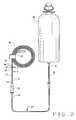
- FIG. 2is a front elevational view of the tube assembly and fluid source according to the present invention
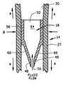
- FIG. 3is a front view of the valve device disposed within the lumen of the second tube segment with the slit in the closed position according to the present invention
- FIG. 4is a perspective view of the valve device according to the present invention.
- FIG. 5is a side elevational view of the valve device according to the present invention.
- FIG. 6is a cross-sectional view of the valve device taken along line 6 — 6 of FIG. 3 according to the present invention
- FIG. 7is a rear elevational view of the valve device according to the present invention.
- FIG. 8is a front view of the valve device disposed within the lumen of the second tube segment with the slit in the open position. according to the present invention.
- FIG. 9is a cross-sectional view of the valve device taken along line 9 — 9 of FIG. 8 according to the present invention.
- FIG. 10is a partial cross-sectional view of the valve device showing slots adapted to retain an insert according to the present invention
- FIG. 11is a perspective view of the preferred embodiment of an insert having a thin oval body according to the present invention.
- FIG. 12is a perspective view of an alternative embodiment of the insert having an elongated rectangular body according to the present invention.
- FIG. 13is a perspective view of the valve device with the alternative embodiment of the insert of FIG. 12 shown in partial phantom;
- FIG. 14is a perspective view of another alternative embodiment of the insert having an elongated oval body according to the present invention.
- valve device 16is illustrated and generally indicated as 16 in FIG. 1 .
- the valve device 16is used in a fluid administration system 10 which comprises a tube assembly 14 engaged with a pump 12 and a fluid source 40 (FIG. 2 ).
- proximalshall refer to the end of the valve device 16 or tube assembly 14 farthest from fluid source 40
- distalshall refer to the end of device 16 or assembly 14 closest to fluid source 40 .
- Pump 12is preferably a rotary peristaltic pump as shown in FIG. 1 .
- pump 12includes a rotor 18 and a control panel 20 located adjacent rotor 18 which permits a user to monitor and adjust the rotation rate of rotor 18 for controlling fluid flow rate by pump 12 .
- a first recess 22 and a second recess 24are formed above rotor 18 for engaging portions of tube assembly 14 which will be discussed in greater detail below.
- tube assembly 14includes a first tube segment 26 , a second tube segment 27 , and a third tube segment 28 which are in communication with one another.
- Each of the first, second and third tube segments 26 , 27 , and 28have respective distal and proximal ends 31 , 32 .
- fluid source 40for providing fluid to a patient while the proximal end 32 thereof is attached to a drip chamber 33 .
- drip chamber 33has an abutment surface 34 which interconnects proximal end 32 of first tube segment 26 with distal end 31 of second tube segment 27 .
- proximal end 32 of second tube segment 27is then interconnected to distal end 31 of third tube segment 28 by a coupling 36 having an external flange 38 .
- third tube segment 28terminates at a proximal end 32 which is attached to an enteral or parenteral connection (not shown) made with the patient for delivery of fluid.
- drip chamber 33 and coupling 36are sized and shaped to be captured within first recess 22 and second recess 24 , respectively.
- the length of second tube segment 22permits drip chamber 33 and coupling 36 to be properly captured within first recess 22 and second recess 24 , respectively, while also stretching second tube segment 27 as it is engaged around rotor 18 .
- the amount of tensile force A (FIG. 9) applied along second tube segment 27 as it is engaged around rotor 18may be varied by altering the length of tube segment 27 .
- each tube segment 26 , 27 and 28 of tube assembly 14includes a lumen 30 formed therethrough by which fluid may pass from fluid source 40 .
- valve device 16comprises a hollow flexible body 44 having a tapered portion 60 .
- tapered portion 60 formed at a distal end 47 of body 44includes opposing beveled surfaces 62 bounded by a pair of side walls 63 with surfaces 62 having ends 48 which define a slit 50 .
- Body 44further includes a proximal end 46 , as shown in FIG. 7, which forms an outlet 52 in communication with a passage 64 such that fluid which enters slit 50 may pass along passage 64 and out outlet 52 .
- the intersection between tapered portion 60 and cylindrical portion 56defines a shoulder 54 .
- cylindrical portion 56may simply taper gradually into tapered portion 60 without departing from the scope of the present invention.
- valve device 16is preferably disposed within lumen 30 of second tube segment 27 adjacent coupling 36 (FIG. 2) with slit 50 facing the direction of fluid flow while outlet 52 is oriented toward proximal end 32 of third tube segment 28 (FIG. 2 ).
- the cylindrical portion 56is sized and shaped to sealingly engage against the inner surface of lumen 30 and prevent fluid flow around valve device 16 .
- the ends 48 of opposing beveled surfaces 62substantially confront one another such that slit 50 is maintained in a closed position, thereby preventing fluid. flow through passage: 64 of hollow body 44 .
- fluid flowmay be established through valve device 16 by applying tensile force A along second tube segment 27 by engaging portion of tube segment 27 around rotor 18 .
- tensile force AWhen engaging second tube segment 27 around rotor 18 , tube segment 27 is placed in a stretched condition as tensile force A is applied the tealong.
- tensile force Aalso causes a transverse force B to be applied to cylindrical portion 56 which decreases the inner diameter of the lumen 30 as a result of second tube segment 27 being placed in the stretched condition.
- body 44becomes elongated which urges the ends 48 of opposing beveled surfaces 62 away from one. another and opens slit 50 to permit fluid flow therethrough. Referring to FIG.
- the decrease in the inner diameter of lumen 30is directly proportional to the tensile force applied to second tube segment 27 . Accordingly, the amount second tube segment 27 is stretched due to the tensile force applied thereto may be modified by changing the length of second tube segment 27 .
- the amount that the inner diameter of lumen 30 is decreasedmay be accomplished by pre-stressing body 44 of valve device 16 in a direction approximately transverse to slit 50 , thereby biasing body 44 into a generally oval shaped configuration.
- valve device 16may be pre-stressed by placing an oval-shaped insert 66 , as shown in FIG. 11, into passage 64 of body 44 .
- insert 66comprises a thin oval body 68 defining apertures 70 for allowing fluid flow therethrough.
- insert 66also includes tabs 72 which are sized and shaped to be received within a respective slots 65 formed along the inner surface of passage 64 , as illustrated in FIG. 10, for facilitating retention of insert 66 within valve device 16 . It is contemplated that insert 66 may have one or more tabs 72 or one or more apertures 70 .
- insert 166which is shown having a generally rectangular-shaped body 74 which biases body 44 into a generally oval shaped configuration when inserted through opening 52 and retained within passage 64 by opposing tabs 172 which securely engage slots 65 formed along the inner surface of passage 64 .
- insert 266has an elongated oval body 276 with no tabs required to retain insert 266 inside valve device 16 . Insert 266 is inserted through opening 52 and substantially fills passage 64 such that body 44 takes a generally oval shaped configuration.
- valve device 16prevents fluid free flow into third tube segment 28 .
- airis cleared from third tube segment 28 when the user primes tube assembly 14 by applying a tensile force A along the area of the tube assembly 114 adjacent valve device 16 to place second tube segment 27 in the stretched condition and open slit 50 to fluid flow. Applying tensile force A causes second tube segment 27 to stretch which in turn exerts a transverse force B against body 44 that decreases the inner diameter of lumen 30 .
- the decrease in the inner diameter of lumen 30elongates body 44 and urges the ends 48 of opposing beveled surfaces 62 away from one another, thereby placing slit 50 in the open position and allow fluid flow therethrough.
- the usercan manually prime the tube assembly 14 by pinching body 44 of valve device 16 in a direction transverse to slit 50 .
- the ends 48 of the opposed beveled surfaces 62are urged away form one another which opens slit 50 such that fluid flow may be established through lumen 30 .
- the proximal end 32 of third tube segment 28may be connected to an enteral or parenteral connection on the patient.
- a pump 12is connected in-line along tube assembly 14 .
- abutment surface 34 of drip chamber 33is engaged with first recess 22 and second tube segment 27 is stretched by the user around rotor 18 .
- the external flange 38 of coupling 36is then engaged within second recess 24 in order to retain second tube segment 27 in the stretched condition. Due to the tensile force applied along second tube segment 27 , the inner diameter of lumen 30 is decreased such that the inner surface of lumen 30 confronts and elongates body 44 .
Landscapes
- Health & Medical Sciences (AREA)
- Heart & Thoracic Surgery (AREA)
- Animal Behavior & Ethology (AREA)
- Veterinary Medicine (AREA)
- Biomedical Technology (AREA)
- Engineering & Computer Science (AREA)
- Hematology (AREA)
- Life Sciences & Earth Sciences (AREA)
- Anesthesiology (AREA)
- General Health & Medical Sciences (AREA)
- Public Health (AREA)
- Vascular Medicine (AREA)
- Pulmonology (AREA)
- Infusion, Injection, And Reservoir Apparatuses (AREA)
- Check Valves (AREA)
- Rigid Pipes And Flexible Pipes (AREA)
- Feeding And Controlling Fuel (AREA)
- Preventing Unauthorised Actuation Of Valves (AREA)
- Pipe Accessories (AREA)
Abstract
Description
Claims (28)
Priority Applications (14)
| Application Number | Priority Date | Filing Date | Title |
|---|---|---|---|
| US09/514,667US6461335B1 (en) | 2000-02-28 | 2000-02-28 | Tube dependent anti-free-flow valve |
| ES01921752TES2270994T3 (en) | 2000-02-28 | 2001-01-16 | VALVE AGAINST THE FREE FLOW DEPENDENT ON THE TUBE. |
| PCT/IB2001/000718WO2001064265A1 (en) | 2000-02-28 | 2001-01-16 | Tube dependent anti-free-flow valve |
| CZ20023042ACZ20023042A3 (en) | 2000-02-28 | 2001-01-16 | Pipe valve for preventing free flow |
| AU48716/01AAU782547B2 (en) | 2000-02-28 | 2001-01-16 | Tube dependent anti-free-flow valve |
| PL01365121APL365121A1 (en) | 2000-02-28 | 2001-01-16 | Tube dependent anti-free-flow valve |
| DK01921752TDK1259273T3 (en) | 2000-02-28 | 2001-01-16 | Hose dependent anti-free flow valve |
| EP01921752AEP1259273B1 (en) | 2000-02-28 | 2001-01-16 | Tube dependent anti-free-flow valve |
| CA002401366ACA2401366C (en) | 2000-02-28 | 2001-01-16 | Tube dependent anti-free-flow valve |
| JP2001563161AJP4450537B2 (en) | 2000-02-28 | 2001-01-16 | Tube-dependent free flow prevention valve |
| KR1020027011235AKR100749294B1 (en) | 2000-02-28 | 2001-01-16 | Tube-Dependent Free Flow Valves |
| AT01921752TATE342078T1 (en) | 2000-02-28 | 2001-01-16 | TUBE ACTUATED VALVE TO PREVENT FREE FLOW |
| PT01921752TPT1259273E (en) | 2000-02-28 | 2001-01-16 | Tube dependent anti-free-flow valve |
| DE60123757TDE60123757T2 (en) | 2000-02-28 | 2001-01-16 | PIPE-OPERATED VALVE TO PREVENT FREE FLOW |
Applications Claiming Priority (1)
| Application Number | Priority Date | Filing Date | Title |
|---|---|---|---|
| US09/514,667US6461335B1 (en) | 2000-02-28 | 2000-02-28 | Tube dependent anti-free-flow valve |
Publications (1)
| Publication Number | Publication Date |
|---|---|
| US6461335B1true US6461335B1 (en) | 2002-10-08 |
Family
ID=24048195
Family Applications (1)
| Application Number | Title | Priority Date | Filing Date |
|---|---|---|---|
| US09/514,667Expired - LifetimeUS6461335B1 (en) | 2000-02-28 | 2000-02-28 | Tube dependent anti-free-flow valve |
Country Status (14)
| Country | Link |
|---|---|
| US (1) | US6461335B1 (en) |
| EP (1) | EP1259273B1 (en) |
| JP (1) | JP4450537B2 (en) |
| KR (1) | KR100749294B1 (en) |
| AT (1) | ATE342078T1 (en) |
| AU (1) | AU782547B2 (en) |
| CA (1) | CA2401366C (en) |
| CZ (1) | CZ20023042A3 (en) |
| DE (1) | DE60123757T2 (en) |
| DK (1) | DK1259273T3 (en) |
| ES (1) | ES2270994T3 (en) |
| PL (1) | PL365121A1 (en) |
| PT (1) | PT1259273E (en) |
| WO (1) | WO2001064265A1 (en) |
Cited By (27)
| Publication number | Priority date | Publication date | Assignee | Title |
|---|---|---|---|---|
| US20020007156A1 (en)* | 2000-05-11 | 2002-01-17 | Miles Scott D. | Apparatus and method for preventing free flow in an infusion line |
| US20040082909A1 (en)* | 2002-10-28 | 2004-04-29 | Benedict Shia | Automatic valve |
| US20040220542A1 (en)* | 2000-05-11 | 2004-11-04 | David Cise | Apparatus and method for preventing free flow in an infusion line |
| US20050199446A1 (en)* | 2004-03-15 | 2005-09-15 | Nippon Thompson Co. Ltd. | Lubricating plug and stud-type traking wheel with the same |
| GB2414678A (en)* | 2002-10-15 | 2005-12-07 | Enomoto Co Ltd | Medical Valve Assembly |
| US20060058740A1 (en)* | 2000-05-11 | 2006-03-16 | David Cise | Apparatus and method for preventing free flow in an infusion line |
| US20060129092A1 (en)* | 2002-10-28 | 2006-06-15 | Sherwood Services Ag | Single lumen adapter for automatic valve |
| USD536783S1 (en) | 2002-06-28 | 2007-02-13 | Zevex, Inc. | Enteral feeding pump cassette connector |
| US20070265581A1 (en)* | 2006-05-15 | 2007-11-15 | Tyco Healthcare Group Lp | Liquid Coinjector |
| US20100082001A1 (en)* | 2008-04-01 | 2010-04-01 | Kent Beck | Anti-free flow mechanism for enteral feeding pumps |
| USD615644S1 (en) | 2008-08-15 | 2010-05-11 | Ost Medical, Inc. | Anti-free flow modulator |
| USD634005S1 (en) | 2002-09-09 | 2011-03-08 | Zevex, Inc. | In-line occluder |
| USD635664S1 (en) | 2002-09-09 | 2011-04-05 | Zevex, Inc. | In-line occluder |
| US7998121B2 (en) | 2009-02-06 | 2011-08-16 | Zevex, Inc. | Automatic safety occluder |
| USD672455S1 (en) | 2010-10-01 | 2012-12-11 | Zevex, Inc. | Fluid delivery cassette |
| US8425470B2 (en) | 2008-04-01 | 2013-04-23 | Zevex, Inc. | Anti-free-flow mechanism for enteral feeding pumps |
| US8911414B2 (en) | 2010-10-01 | 2014-12-16 | Zevex, Inc. | Anti free-flow occluder and priming actuator pad |
| US9017296B2 (en) | 2008-04-01 | 2015-04-28 | Zevex, Inc. | Safety occluder and method of use |
| US20160346168A1 (en)* | 2013-05-24 | 2016-12-01 | Qingyang SUN | Nursing bottle having air returning function |
| CN106361577A (en)* | 2016-12-15 | 2017-02-01 | 齐齐哈尔医学院附属第医院 | Split type nasal feeding tube provided with negative pressure valve |
| US20180209562A1 (en)* | 2017-01-23 | 2018-07-26 | Oculus Vr, Llc | Fluidic switching devices |
| US20190063619A1 (en)* | 2017-08-23 | 2019-02-28 | Facebook Technologies, Llc | Fluidic switching devices |
| US10422362B2 (en) | 2017-09-05 | 2019-09-24 | Facebook Technologies, Llc | Fluidic pump and latch gate |
| US10591933B1 (en) | 2017-11-10 | 2020-03-17 | Facebook Technologies, Llc | Composable PFET fluidic device |
| US11098737B1 (en) | 2019-06-27 | 2021-08-24 | Facebook Technologies, Llc | Analog fluidic devices and systems |
| US11231055B1 (en) | 2019-06-05 | 2022-01-25 | Facebook Technologies, Llc | Apparatus and methods for fluidic amplification |
| US11371619B2 (en) | 2019-07-19 | 2022-06-28 | Facebook Technologies, Llc | Membraneless fluid-controlled valve |
Families Citing this family (7)
| Publication number | Priority date | Publication date | Assignee | Title |
|---|---|---|---|---|
| IL142446A (en)* | 2001-04-04 | 2009-07-20 | Caesarea Medical Electronics Ltd | Flow set and a method to identify said flow set by a liquid pump |
| US6908459B2 (en)* | 2001-12-07 | 2005-06-21 | Becton, Dickinson And Company | Needleless luer access connector |
| DE10307722A1 (en)* | 2002-03-07 | 2003-11-13 | Enomoto Co Ltd | Medical device |
| EP1747755B1 (en)* | 2004-05-17 | 2018-07-04 | Sekisui Chemical Co., Ltd. | Backflow preventing structure of blood sampler, lure needle, blood sampling needle and blood sampling holder |
| US7462170B2 (en)* | 2004-05-25 | 2008-12-09 | Covidien Ag | Administration feeding set and valve mechanism |
| JP5998499B2 (en)* | 2011-02-14 | 2016-09-28 | 株式会社ジェイ・エム・エス | Extension tube |
| ES2449642B1 (en)* | 2014-01-03 | 2014-10-16 | Carlos ESTEVE PIÑEIRO | Air occluder for serum infusion systems and / or medication |
Citations (19)
| Publication number | Priority date | Publication date | Assignee | Title |
|---|---|---|---|---|
| US3311268A (en) | 1964-11-16 | 1967-03-28 | Roehr Products Company Inc | Intravenous feed bottle |
| US3460529A (en) | 1965-06-30 | 1969-08-12 | Gino Leucci | Sterile device for extracting urine samples and the like and package for same |
| US3547401A (en) | 1968-06-07 | 1970-12-15 | Abbott Lab | Foldable bellows valve |
| US4263932A (en) | 1977-08-31 | 1981-04-28 | Agfa-Gevaert, A.G. | Accurate dosing of regenerating fluid to processing-fluid-tank in film developing machine |
| US4337770A (en)* | 1979-06-07 | 1982-07-06 | Young James E | Flow regulating device for arterial catheter systems |
| US4395260A (en) | 1981-06-01 | 1983-07-26 | Sorenson Research Co., Inc. | Drip chamber |
| US4394862A (en)* | 1980-08-25 | 1983-07-26 | Baxter Travenol Laboratories, Inc. | Metering apparatus with downline pressure monitoring system |
| US4527588A (en)* | 1983-12-14 | 1985-07-09 | Warner-Lambert Company | Safety valve |
| US4615693A (en) | 1984-03-27 | 1986-10-07 | Nypro Inc. | Administration of fluids |
| US4850393A (en) | 1988-08-01 | 1989-07-25 | Rockland Form-A-Plastic, Inc. | All-plastic check valve |
| US5019055A (en) | 1989-12-22 | 1991-05-28 | Boyle Matthew O | Flow regulator and method |
| US5261459A (en)* | 1992-12-07 | 1993-11-16 | Vernay Laboratories, Inc. | Miniature duckbill valve having a low cracking pressure and high flow rate |
| US5267586A (en) | 1991-11-08 | 1993-12-07 | Planmeca Oy | Shutoff valve mechanism for the oral evacuator of a dental unit |
| CA2076512A1 (en)* | 1990-12-13 | 1994-02-21 | Michael Alexeus | Infusion system |
| US5396925A (en)* | 1993-12-16 | 1995-03-14 | Abbott Laboratories | Anti-free flow valve, enabling fluid flow as a function of pressure and selectively opened to enable free flow |
| US5853397A (en)* | 1993-12-13 | 1998-12-29 | Migada, Inc. | Medical infusion apparatus including safety valve |
| US5868715A (en) | 1997-11-13 | 1999-02-09 | Tung; Chen Chang | Intravenous metering device having automatic stopper |
| US5954485A (en)* | 1996-08-14 | 1999-09-21 | Sims Deltec, Inc. | Free-flow protection devices and methods |
| US6092551A (en)* | 1998-05-19 | 2000-07-25 | Chesebrough-Pond's Usa Co., Division Of Conopco, Inc. | Duckbill valve |
Family Cites Families (4)
| Publication number | Priority date | Publication date | Assignee | Title |
|---|---|---|---|---|
| US4187057A (en)* | 1978-01-11 | 1980-02-05 | Stewart-Naumann Laboratories, Inc. | Peristaltic infusion pump and disposable cassette for use therewith |
| US4689043A (en) | 1986-03-19 | 1987-08-25 | Imed Corporation | IV tube activator |
| DE4126088C1 (en)* | 1991-08-07 | 1993-01-14 | B. Braun Melsungen Ag, 3508 Melsungen, De | Peristaltic pump hose with inlet and outlet sections, and pumping middle one - has stationary, coaxial plug inside deformable part away from its wall |
| US5704582A (en) | 1996-11-13 | 1998-01-06 | Chrysler Corporation | Self-adjusting support blocks |
- 2000
- 2000-02-28USUS09/514,667patent/US6461335B1/ennot_activeExpired - Lifetime
- 2001
- 2001-01-16KRKR1020027011235Apatent/KR100749294B1/ennot_activeExpired - Lifetime
- 2001-01-16DKDK01921752Tpatent/DK1259273T3/enactive
- 2001-01-16WOPCT/IB2001/000718patent/WO2001064265A1/enactiveIP Right Grant
- 2001-01-16AUAU48716/01Apatent/AU782547B2/ennot_activeExpired
- 2001-01-16PTPT01921752Tpatent/PT1259273E/enunknown
- 2001-01-16ATAT01921752Tpatent/ATE342078T1/enactive
- 2001-01-16ESES01921752Tpatent/ES2270994T3/ennot_activeExpired - Lifetime
- 2001-01-16PLPL01365121Apatent/PL365121A1/enunknown
- 2001-01-16CACA002401366Apatent/CA2401366C/ennot_activeExpired - Lifetime
- 2001-01-16EPEP01921752Apatent/EP1259273B1/ennot_activeExpired - Lifetime
- 2001-01-16JPJP2001563161Apatent/JP4450537B2/ennot_activeExpired - Lifetime
- 2001-01-16DEDE60123757Tpatent/DE60123757T2/ennot_activeExpired - Lifetime
- 2001-01-16CZCZ20023042Apatent/CZ20023042A3/enunknown
Patent Citations (19)
| Publication number | Priority date | Publication date | Assignee | Title |
|---|---|---|---|---|
| US3311268A (en) | 1964-11-16 | 1967-03-28 | Roehr Products Company Inc | Intravenous feed bottle |
| US3460529A (en) | 1965-06-30 | 1969-08-12 | Gino Leucci | Sterile device for extracting urine samples and the like and package for same |
| US3547401A (en) | 1968-06-07 | 1970-12-15 | Abbott Lab | Foldable bellows valve |
| US4263932A (en) | 1977-08-31 | 1981-04-28 | Agfa-Gevaert, A.G. | Accurate dosing of regenerating fluid to processing-fluid-tank in film developing machine |
| US4337770A (en)* | 1979-06-07 | 1982-07-06 | Young James E | Flow regulating device for arterial catheter systems |
| US4394862A (en)* | 1980-08-25 | 1983-07-26 | Baxter Travenol Laboratories, Inc. | Metering apparatus with downline pressure monitoring system |
| US4395260A (en) | 1981-06-01 | 1983-07-26 | Sorenson Research Co., Inc. | Drip chamber |
| US4527588A (en)* | 1983-12-14 | 1985-07-09 | Warner-Lambert Company | Safety valve |
| US4615693A (en) | 1984-03-27 | 1986-10-07 | Nypro Inc. | Administration of fluids |
| US4850393A (en) | 1988-08-01 | 1989-07-25 | Rockland Form-A-Plastic, Inc. | All-plastic check valve |
| US5019055A (en) | 1989-12-22 | 1991-05-28 | Boyle Matthew O | Flow regulator and method |
| CA2076512A1 (en)* | 1990-12-13 | 1994-02-21 | Michael Alexeus | Infusion system |
| US5267586A (en) | 1991-11-08 | 1993-12-07 | Planmeca Oy | Shutoff valve mechanism for the oral evacuator of a dental unit |
| US5261459A (en)* | 1992-12-07 | 1993-11-16 | Vernay Laboratories, Inc. | Miniature duckbill valve having a low cracking pressure and high flow rate |
| US5853397A (en)* | 1993-12-13 | 1998-12-29 | Migada, Inc. | Medical infusion apparatus including safety valve |
| US5396925A (en)* | 1993-12-16 | 1995-03-14 | Abbott Laboratories | Anti-free flow valve, enabling fluid flow as a function of pressure and selectively opened to enable free flow |
| US5954485A (en)* | 1996-08-14 | 1999-09-21 | Sims Deltec, Inc. | Free-flow protection devices and methods |
| US5868715A (en) | 1997-11-13 | 1999-02-09 | Tung; Chen Chang | Intravenous metering device having automatic stopper |
| US6092551A (en)* | 1998-05-19 | 2000-07-25 | Chesebrough-Pond's Usa Co., Division Of Conopco, Inc. | Duckbill valve |
Cited By (50)
| Publication number | Priority date | Publication date | Assignee | Title |
|---|---|---|---|---|
| US6979311B2 (en) | 2000-05-11 | 2005-12-27 | Zevex, Inc. | Apparatus and method for preventing free flow in an infusion line |
| US20060058740A1 (en)* | 2000-05-11 | 2006-03-16 | David Cise | Apparatus and method for preventing free flow in an infusion line |
| US7976513B2 (en) | 2000-05-11 | 2011-07-12 | Zevex, Inc. | Apparatus and method for selectively controlling flow in an infusion line |
| US20040220542A1 (en)* | 2000-05-11 | 2004-11-04 | David Cise | Apparatus and method for preventing free flow in an infusion line |
| US20020007156A1 (en)* | 2000-05-11 | 2002-01-17 | Miles Scott D. | Apparatus and method for preventing free flow in an infusion line |
| US20050119625A1 (en)* | 2000-05-11 | 2005-06-02 | Scott Miles | Apparatus and method for preventing free flow in an infusion line |
| US20050283121A1 (en)* | 2000-05-11 | 2005-12-22 | David Cise | Apparatus and method for preventing free flow in an infusion line |
| US7815612B2 (en)* | 2000-05-11 | 2010-10-19 | Zevex, Inc. | Apparatus and method for preventing free flow in an infusion line |
| US6623447B2 (en)* | 2000-05-11 | 2003-09-23 | Zevex, Inc. | Apparatus and method for preventing free flow in an infusion line |
| US7367963B2 (en) | 2000-05-11 | 2008-05-06 | Zevex, Inc. | Apparatus and method for preventing free flow in an infusion line |
| USD536783S1 (en) | 2002-06-28 | 2007-02-13 | Zevex, Inc. | Enteral feeding pump cassette connector |
| USD634005S1 (en) | 2002-09-09 | 2011-03-08 | Zevex, Inc. | In-line occluder |
| USD635664S1 (en) | 2002-09-09 | 2011-04-05 | Zevex, Inc. | In-line occluder |
| GB2414678A (en)* | 2002-10-15 | 2005-12-07 | Enomoto Co Ltd | Medical Valve Assembly |
| US20060129092A1 (en)* | 2002-10-28 | 2006-06-15 | Sherwood Services Ag | Single lumen adapter for automatic valve |
| US7097632B2 (en) | 2002-10-28 | 2006-08-29 | Sherwood Services Ag | Automatic valve |
| CN100534545C (en)* | 2002-10-28 | 2009-09-02 | 舍伍德服务公开股份有限公司 | Automatic valve |
| US20040082909A1 (en)* | 2002-10-28 | 2004-04-29 | Benedict Shia | Automatic valve |
| US7713246B2 (en) | 2002-10-28 | 2010-05-11 | Covidien Ag | Automatic valve |
| WO2004039286A3 (en)* | 2002-10-28 | 2005-02-03 | Sherwood Serv Ag | Automatic valve |
| US20080179882A1 (en)* | 2003-10-28 | 2008-07-31 | Hanlon James G | Fluid Adapter for Valve |
| US7823697B2 (en)* | 2004-03-15 | 2010-11-02 | Nippon Thompson Co., Ltd. | Lubricating plug and stud-type tracking wheel with the same |
| US20050199446A1 (en)* | 2004-03-15 | 2005-09-15 | Nippon Thompson Co. Ltd. | Lubricating plug and stud-type traking wheel with the same |
| US7806874B2 (en) | 2006-05-15 | 2010-10-05 | Tyco Healthcare Group Lp | Liquid coinjector |
| US20070265581A1 (en)* | 2006-05-15 | 2007-11-15 | Tyco Healthcare Group Lp | Liquid Coinjector |
| US20100082001A1 (en)* | 2008-04-01 | 2010-04-01 | Kent Beck | Anti-free flow mechanism for enteral feeding pumps |
| US9017296B2 (en) | 2008-04-01 | 2015-04-28 | Zevex, Inc. | Safety occluder and method of use |
| US8876787B2 (en) | 2008-04-01 | 2014-11-04 | Zevex, Inc. | Anti-free-flow mechanism for enteral feeding pumps |
| US8343111B2 (en) | 2008-04-01 | 2013-01-01 | Zevex, Inc. | Anti-free flow mechanism for enteral feeding pumps |
| US8425470B2 (en) | 2008-04-01 | 2013-04-23 | Zevex, Inc. | Anti-free-flow mechanism for enteral feeding pumps |
| USD615644S1 (en) | 2008-08-15 | 2010-05-11 | Ost Medical, Inc. | Anti-free flow modulator |
| US8491543B2 (en) | 2009-02-06 | 2013-07-23 | Zevex, Inc. | Automatic safety occluder |
| US7998121B2 (en) | 2009-02-06 | 2011-08-16 | Zevex, Inc. | Automatic safety occluder |
| USD672455S1 (en) | 2010-10-01 | 2012-12-11 | Zevex, Inc. | Fluid delivery cassette |
| US8911414B2 (en) | 2010-10-01 | 2014-12-16 | Zevex, Inc. | Anti free-flow occluder and priming actuator pad |
| US20160346168A1 (en)* | 2013-05-24 | 2016-12-01 | Qingyang SUN | Nursing bottle having air returning function |
| CN106361577A (en)* | 2016-12-15 | 2017-02-01 | 齐齐哈尔医学院附属第医院 | Split type nasal feeding tube provided with negative pressure valve |
| CN106361577B (en)* | 2016-12-15 | 2023-01-31 | 齐齐哈尔医学院附属第一医院 | Split type negative pressure valve type nasal feeding tube |
| US10514111B2 (en)* | 2017-01-23 | 2019-12-24 | Facebook Technologies, Llc | Fluidic switching devices |
| US10989330B1 (en) | 2017-01-23 | 2021-04-27 | Facebook Technologies, Llc | Fluidic switching devices |
| US20180209562A1 (en)* | 2017-01-23 | 2018-07-26 | Oculus Vr, Llc | Fluidic switching devices |
| US20190063619A1 (en)* | 2017-08-23 | 2019-02-28 | Facebook Technologies, Llc | Fluidic switching devices |
| US10648573B2 (en)* | 2017-08-23 | 2020-05-12 | Facebook Technologies, Llc | Fluidic switching devices |
| US11193597B1 (en) | 2017-08-23 | 2021-12-07 | Facebook Technologies, Llc | Fluidic devices, haptic systems including fluidic devices, and related methods |
| US10422362B2 (en) | 2017-09-05 | 2019-09-24 | Facebook Technologies, Llc | Fluidic pump and latch gate |
| US10989233B2 (en) | 2017-09-05 | 2021-04-27 | Facebook Technologies, Llc | Fluidic pump and latch gate |
| US10591933B1 (en) | 2017-11-10 | 2020-03-17 | Facebook Technologies, Llc | Composable PFET fluidic device |
| US11231055B1 (en) | 2019-06-05 | 2022-01-25 | Facebook Technologies, Llc | Apparatus and methods for fluidic amplification |
| US11098737B1 (en) | 2019-06-27 | 2021-08-24 | Facebook Technologies, Llc | Analog fluidic devices and systems |
| US11371619B2 (en) | 2019-07-19 | 2022-06-28 | Facebook Technologies, Llc | Membraneless fluid-controlled valve |
Also Published As
| Publication number | Publication date |
|---|---|
| AU4871601A (en) | 2001-09-12 |
| CA2401366A1 (en) | 2001-09-07 |
| WO2001064265B1 (en) | 2002-03-21 |
| ES2270994T3 (en) | 2007-04-16 |
| WO2001064265A8 (en) | 2002-07-04 |
| ATE342078T1 (en) | 2006-11-15 |
| DE60123757T2 (en) | 2007-08-16 |
| EP1259273B1 (en) | 2006-10-11 |
| CZ20023042A3 (en) | 2003-02-12 |
| AU782547B2 (en) | 2005-08-11 |
| PT1259273E (en) | 2007-01-31 |
| PL365121A1 (en) | 2004-12-27 |
| KR100749294B1 (en) | 2007-08-14 |
| JP2003525085A (en) | 2003-08-26 |
| WO2001064265A1 (en) | 2001-09-07 |
| DK1259273T3 (en) | 2007-02-12 |
| KR20020092970A (en) | 2002-12-12 |
| JP4450537B2 (en) | 2010-04-14 |
| CA2401366C (en) | 2009-03-31 |
| EP1259273A1 (en) | 2002-11-27 |
| DE60123757D1 (en) | 2006-11-23 |
Similar Documents
| Publication | Publication Date | Title |
|---|---|---|
| US6461335B1 (en) | Tube dependent anti-free-flow valve | |
| AU2001253883B2 (en) | Drip chamber anti free flow device | |
| US6494864B1 (en) | Inner lumen anti-free flow device | |
| AU2001253883A1 (en) | Drip chamber anti free flow device | |
| US4684364A (en) | Safety arrangement for preventing air embolism during intravenous procedures | |
| US7815612B2 (en) | Apparatus and method for preventing free flow in an infusion line | |
| US7150727B2 (en) | Apparatus and method for preventing free flow in an infusion line | |
| US4950254A (en) | Valve means for enteral therapy administration set | |
| US4140118A (en) | Cassette chamber for intravenous delivery system | |
| EP0927061B1 (en) | Valve apparatus for use with an iv set | |
| US5226886A (en) | Ambulatory tubing set with anti-siphon valve | |
| US6454742B1 (en) | Valve cuff for a fluid administration system | |
| JP2014140771A (en) | Anti-free-flow mechanism for enteral feeding pumps | |
| ES2970446T3 (en) | Cassette for a flow control device | |
| US20030229309A1 (en) | Inner lumen anti-free flow device | |
| USH2090H1 (en) | One-piece unitary occluder | |
| US20040249350A1 (en) | Device for fluid delivery system | |
| JPS5829335Y2 (en) | flow control device | |
| WO1996017636A1 (en) | Infusion apparatus comprising a deformable tube |
Legal Events
| Date | Code | Title | Description |
|---|---|---|---|
| AS | Assignment | Owner name:SHERWOOD SERVICES, AG, MASSACHUSETTS Free format text:ASSIGNMENT OF ASSIGNORS INTEREST;ASSIGNOR:NOECKER, ANGELA M.;REEL/FRAME:010701/0573 Effective date:20000315 | |
| AS | Assignment | Owner name:SHERWOOD SERVICES, AG, SWITZERLAND Free format text:RE-RECORD TO CORRECT THE ASSIGNEE'S ADDRESS, PREVIOUSLY RECORDED AT REEL 010701, FRAME 0573.;ASSIGNOR:NOECKER, ANGELA M.;REEL/FRAME:011001/0113 Effective date:20000315 | |
| STCF | Information on status: patent grant | Free format text:PATENTED CASE | |
| FPAY | Fee payment | Year of fee payment:4 | |
| AS | Assignment | Owner name:COVIDIEN AG, SWITZERLAND Free format text:CHANGE OF NAME;ASSIGNOR:SHERWOOD SERVICES AG;REEL/FRAME:021371/0142 Effective date:20070309 | |
| FPAY | Fee payment | Year of fee payment:8 | |
| FPAY | Fee payment | Year of fee payment:12 | |
| AS | Assignment | Owner name:CARDINAL HEALTH IRELAND UNLIMITED COMPANY, IRELAND Free format text:ASSIGNMENT OF ASSIGNORS INTEREST;ASSIGNORS:COVIDIEN AG;COVIDIEN FINANCE INTERNATIONAL GMBH;REEL/FRAME:044763/0234 Effective date:20170729 |