US6461290B1 - Collapsible isolation apparatus - Google Patents
Collapsible isolation apparatusDownload PDFInfo
- Publication number
- US6461290B1 US6461290B1US09/660,432US66043200AUS6461290B1US 6461290 B1US6461290 B1US 6461290B1US 66043200 AUS66043200 AUS 66043200AUS 6461290 B1US6461290 B1US 6461290B1
- Authority
- US
- United States
- Prior art keywords
- patient
- containment
- air
- wall
- interior region
- Prior art date
- Legal status (The legal status is an assumption and is not a legal conclusion. Google has not performed a legal analysis and makes no representation as to the accuracy of the status listed.)
- Expired - Fee Related
Links
- 238000002955isolationMethods0.000titleabstractdescription61
- 238000001914filtrationMethods0.000claimsabstractdescription46
- 239000012298atmosphereSubstances0.000claimsabstractdescription24
- 238000009423ventilationMethods0.000claimsabstractdescription17
- CURLTUGMZLYLDI-UHFFFAOYSA-NCarbon dioxideChemical compoundO=C=OCURLTUGMZLYLDI-UHFFFAOYSA-N0.000claimsabstractdescription12
- 239000000126substanceSubstances0.000claimsabstractdescription8
- 229910002092carbon dioxideInorganic materials0.000claimsabstractdescription6
- 239000001569carbon dioxideSubstances0.000claimsabstractdescription6
- 229920003023plasticPolymers0.000claimsdescription43
- 239000004033plasticSubstances0.000claimsdescription41
- 230000004888barrier functionEffects0.000claimsdescription37
- 230000001681protective effectEffects0.000claimsdescription37
- 239000000463materialSubstances0.000claimsdescription26
- 239000012530fluidSubstances0.000claimsdescription9
- 208000035473Communicable diseaseDiseases0.000claimsdescription7
- 239000012790adhesive layerSubstances0.000claimsdescription7
- 238000005202decontaminationMethods0.000claimsdescription5
- 230000003588decontaminative effectEffects0.000claimsdescription5
- 208000015181infectious diseaseDiseases0.000claimsdescription5
- 239000002985plastic filmSubstances0.000claimsdescription5
- 238000003780insertionMethods0.000claimsdescription4
- 230000037431insertionEffects0.000claimsdescription4
- XLYOFNOQVPJJNP-UHFFFAOYSA-NwaterSubstancesOXLYOFNOQVPJJNP-UHFFFAOYSA-N0.000claimsdescription4
- 230000005540biological transmissionEffects0.000claimsdescription3
- 239000003814drugSubstances0.000claimsdescription3
- 230000002829reductive effectEffects0.000claimsdescription3
- 230000002441reversible effectEffects0.000claimsdescription3
- 238000011109contaminationMethods0.000claimsdescription2
- 238000011049fillingMethods0.000claimsdescription2
- 210000003127kneeAnatomy0.000claimsdescription2
- 238000009825accumulationMethods0.000claims1
- 238000007664blowingMethods0.000claims1
- 230000002787reinforcementEffects0.000claims1
- 210000001562sternumAnatomy0.000claims1
- 238000001802infusionMethods0.000abstractdescription4
- 230000000747cardiac effectEffects0.000abstract1
- 239000003570airSubstances0.000description95
- 210000003128headAnatomy0.000description19
- 210000001624hipAnatomy0.000description14
- 239000000356contaminantSubstances0.000description10
- 210000000038chestAnatomy0.000description8
- 238000001990intravenous administrationMethods0.000description8
- 229920000915polyvinyl chloridePolymers0.000description7
- 239000004800polyvinyl chlorideSubstances0.000description7
- 210000002683footAnatomy0.000description6
- 239000010410layerSubstances0.000description6
- 239000002390adhesive tapeSubstances0.000description5
- 238000004140cleaningMethods0.000description5
- 208000030507AIDSDiseases0.000description4
- 206010052428WoundDiseases0.000description4
- 208000027418Wounds and injuryDiseases0.000description4
- 230000007123defenseEffects0.000description4
- 241000239290AraneaeSpecies0.000description3
- 201000011001Ebola Hemorrhagic FeverDiseases0.000description3
- 241001115402EbolavirusSpecies0.000description3
- 241001115401MarburgvirusSpecies0.000description3
- QVGXLLKOCUKJST-UHFFFAOYSA-Natomic oxygenChemical compound[O]QVGXLLKOCUKJST-UHFFFAOYSA-N0.000description3
- 229920002457flexible plasticPolymers0.000description3
- 230000002452interceptive effectEffects0.000description3
- 210000002445nippleAnatomy0.000description3
- 229910052760oxygenInorganic materials0.000description3
- 239000001301oxygenSubstances0.000description3
- 230000003014reinforcing effectEffects0.000description3
- 238000007789sealingMethods0.000description3
- 206010061192Haemorrhagic feverDiseases0.000description2
- 208000032843HemorrhageDiseases0.000description2
- 239000000853adhesiveSubstances0.000description2
- 230000001070adhesive effectEffects0.000description2
- 230000002411adverseEffects0.000description2
- 239000012080ambient airSubstances0.000description2
- 210000003423ankleAnatomy0.000description2
- 238000005452bendingMethods0.000description2
- 230000000740bleeding effectEffects0.000description2
- 239000002131composite materialSubstances0.000description2
- 201000010099diseaseDiseases0.000description2
- 208000037265diseases, disorders, signs and symptomsDiseases0.000description2
- 230000005484gravityEffects0.000description2
- 210000004247handAnatomy0.000description2
- 239000007788liquidSubstances0.000description2
- 238000012986modificationMethods0.000description2
- 230000004048modificationEffects0.000description2
- 230000003068static effectEffects0.000description2
- 239000000758substrateSubstances0.000description2
- 206010001497AgitationDiseases0.000description1
- 241000193738Bacillus anthracisSpecies0.000description1
- 241000894006BacteriaSpecies0.000description1
- OKTJSMMVPCPJKN-UHFFFAOYSA-NCarbonChemical compound[C]OKTJSMMVPCPJKN-UHFFFAOYSA-N0.000description1
- 208000037319Hepatitis infectiousDiseases0.000description1
- 239000004677NylonSubstances0.000description1
- 210000001015abdomenAnatomy0.000description1
- 239000003124biologic agentSubstances0.000description1
- 230000036772blood pressureEffects0.000description1
- 244000309466calfSpecies0.000description1
- 229910052799carbonInorganic materials0.000description1
- 239000013043chemical agentSubstances0.000description1
- 238000006243chemical reactionMethods0.000description1
- 230000008878couplingEffects0.000description1
- 238000010168coupling processMethods0.000description1
- 238000005859coupling reactionMethods0.000description1
- 229940079593drugDrugs0.000description1
- 230000005611electricityEffects0.000description1
- 230000035876healingEffects0.000description1
- 230000036541healthEffects0.000description1
- 208000006454hepatitisDiseases0.000description1
- 231100000283hepatitisToxicity0.000description1
- 208000005252hepatitis ADiseases0.000description1
- 230000002458infectious effectEffects0.000description1
- 239000002648laminated materialSubstances0.000description1
- 238000011068loading methodMethods0.000description1
- 210000003141lower extremityAnatomy0.000description1
- 229920001778nylonPolymers0.000description1
- 230000035699permeabilityEffects0.000description1
- 238000000746purificationMethods0.000description1
- 230000000241respiratory effectEffects0.000description1
- 230000029058respiratory gaseous exchangeEffects0.000description1
- 230000000284resting effectEffects0.000description1
- 210000002784stomachAnatomy0.000description1
- 210000003437tracheaAnatomy0.000description1
- 210000000707wristAnatomy0.000description1
Images


Classifications
- A—HUMAN NECESSITIES
- A62—LIFE-SAVING; FIRE-FIGHTING
- A62B—DEVICES, APPARATUS OR METHODS FOR LIFE-SAVING
- A62B31/00—Containers or portable cabins for affording breathing protection with devices for reconditioning the breathing air or for ventilating, in particular those that are suitable for invalids or small children
- A—HUMAN NECESSITIES
- A61—MEDICAL OR VETERINARY SCIENCE; HYGIENE
- A61G—TRANSPORT, PERSONAL CONVEYANCES, OR ACCOMMODATION SPECIALLY ADAPTED FOR PATIENTS OR DISABLED PERSONS; OPERATING TABLES OR CHAIRS; CHAIRS FOR DENTISTRY; FUNERAL DEVICES
- A61G10/00—Treatment rooms or enclosures for medical purposes
- A61G10/005—Isolators, i.e. enclosures generally comprising flexible walls for maintaining a germ-free environment
- A—HUMAN NECESSITIES
- A61—MEDICAL OR VETERINARY SCIENCE; HYGIENE
- A61B—DIAGNOSIS; SURGERY; IDENTIFICATION
- A61B90/00—Instruments, implements or accessories specially adapted for surgery or diagnosis and not covered by any of the groups A61B1/00 - A61B50/00, e.g. for luxation treatment or for protecting wound edges
- A61B90/40—Apparatus fixed or close to patients specially adapted for providing an aseptic surgical environment
- A—HUMAN NECESSITIES
- A61—MEDICAL OR VETERINARY SCIENCE; HYGIENE
- A61G—TRANSPORT, PERSONAL CONVEYANCES, OR ACCOMMODATION SPECIALLY ADAPTED FOR PATIENTS OR DISABLED PERSONS; OPERATING TABLES OR CHAIRS; CHAIRS FOR DENTISTRY; FUNERAL DEVICES
- A61G1/00—Stretchers
- A—HUMAN NECESSITIES
- A61—MEDICAL OR VETERINARY SCIENCE; HYGIENE
- A61G—TRANSPORT, PERSONAL CONVEYANCES, OR ACCOMMODATION SPECIALLY ADAPTED FOR PATIENTS OR DISABLED PERSONS; OPERATING TABLES OR CHAIRS; CHAIRS FOR DENTISTRY; FUNERAL DEVICES
- A61G2210/00—Devices for specific treatment or diagnosis
- A61G2210/30—Devices for specific treatment or diagnosis for intensive care
Definitions
- This inventionrelates to isolation pods or protective containment devices used to isolate patients and for their transport.
- This transportable containment deviceprovides an impermeable barrier against chemical and biological agents by isolating the injured person within a plastic pressure-type filtered environment, and protects the persons doing the transporting as well as the patient.
- the isolation deviceis capable of being compactly stored and/or easily transported to a site for use in emergencies
- large containers or packsmay store a large number of such containment devices for use by military people in the field against biological or other type of chemical hazards.
- individual isolation devicesmay be conveniently carried or stored on a paramedic emergency vehicle for use in emergencies when transporting one or more infectious patients or person that has AIDS or unknown infectious diseases that need to be controlled against transmission to the people doing the transporting.
- the illustrated and preferred isolation and protective deviceis for use with a litter or stretcher, or other device, which allows the protective barrier to primarily be made of a thin plastic material which is collapsed for compact storage and expanded to receive a patient thereby providing a low-cost, disposable, containment device.
- a drag bottomfor use with the isolation device so that the patient can be carried or dragged by a corpsman or a paramedic across a battlefield to a vehicle for later transport to a hospital, or the like.
- isolation deviceAnother important consideration in the use of such a isolation device is that it be simple to use in times of extreme emergency or excitability, such that personnel opening the device and placing people into the containment device, may not be thinking as clearly as they would normally be thinking and such that untrained personnel may be pressed into service for placing patients in these isolation devices when there is a wide-spread, mass chemical or biological attack. Also, in the case of some diseases, such as hemorrhagic fevers, like Ebola or Marburg viruses, the patients may resist handling and there is a risk in contaminating the handlers unless the device is capable of being opened to a position in which it is very easy to place the patient inside.
- the patientwhen the patient is inside, it is important that the patient not be feeling claustrophobic and, therefore, it is desirable to provide the patient with a clear field of view, as well as to have air flowing the patient's face so that the patient understands that he has plenty of air to breathe while being surrounded by the barrier housing.
- the air being supplied into the containment deviceshould be purified or filtered before flowing across the patient in the protective containment device.
- the surrounding ambient atmosphereis contaminated, then it is desired than the patient be placed within the containment device, and that the air being supplied to the patient be purified and filtered before it is forced into the containment device.
- the air filtered or purified before it is discharged from the interior of the protective device into the ambient atmospherethere are a number of other considerations with respect to air flow that should be met to provide a viable air flow dynamics and an air-tight environment about the patient.
- a Vickers box devicewhich typically cost $20,000 to $30,000 and is heavy, in that it weighs about 200 pounds unloaded.
- Such a deviceis very difficult to store in that it is bulky and not adapted for storage in large number or for use in the event of a biological emergency.
- the Vickers boxis intended for use for transporting victims of natural biological hazards, such victims may include persons who have been infected with Ebola or Marburg virus, anthrax or the like.
- the Vickers boxcomprises a relatively self-contained unit having an external frame with a biological hazard barrier comprising sheet polyvinyl chloride sheet suspended therefrom.
- the framehas a foot rest or step.
- a lower substantially oval loading portprovides access to the interior through which a patient may be carried to rest on a stretcher-like structure.
- the barrierhas a ventilation tube entering its foot end.
- Glove portsare formed on the sides of the frame thereof.
- a pass-through portextends through the barrier approximately near the center of the pod or about waist-high on the patient. There are pairs of glove ports on each side of the unit.
- Intravenous bags and the likemay be suspended from the frame of the unit.
- An intravenous linemay extend through a port in the side of the unit.
- isolation devicewhich can be held in inventory by military or civilian defense organizations at various locations for quick access.
- inexpensive and compact isolation devicesfor inventory by fire departments or other evacuation municipal units where they may be transporting people with airborne infectious diseases or fluid transmitted diseases such as AIDS or hepatitis and where there is bleeding.
- a large amount of moneyis spent cleaning emergency vehicles after the transporting of people who are bleeding and who could possibly have AIDS, infectious hepatitis, etc.
- the amount of time consumed in cleaning such vehicles; and the resultant hazards involved with any improper cleaning to the paramedics and to subsequent patientsis a problem. It would be better if the patient could be placed in the isolation containment device and transported without contaminating the evacuation vehicle such that the isolation device, or pod, itself could be disposed of by burning or by cleaning in some manner for reuse.
- the present inventionis directed to providing the need for such a isolation or containment pod device for an ambulatory or non-ambulatory patient.
- This inventionrelates to a new and improved collapsible, transportable personnel isolation apparatus which minimizes the biological or chemical hazards to or from a patient within the protective containment apparatus.
- the collapsible, transportable containment apparatusmay be used with ambulatory patients in one embodiment or used with non-ambulatory patients in another embodiment.
- the containment deviceis preferably inexpensive in the sense that it can be purchased and stored by the military and/or by fire or civil defense departments in large quantities for use in terrorist attacks and, after use, may be disposed of by burning or the like.
- the collapsible, compact nature of the protective containment deviceallows it to be stored in large numbers on pallets or to require such a small storage space that it can be stored on a civilian or miliary evacuation vehicle and be ready for use when needed.
- the protective containment deviceis provided with various ports, for example glove ports, pass-through ports, access ports for electrocardiac leads, a stethoscope, or a suction pump line, or infusion line ports for infusion lines that are connected to an external intravenous infusion device.
- Other portsmay be provided for extending a ventilation tube to an airway made into the patient's trachea to intubate the patient.
- sufficient glove portsare provided to allow medical personnel access to the patient's head, chest, abdomen and lower extremities.
- the isolation devicemay be used with or as a litter or stretcher with the patient being prone within a thin, plastic housing which is reinforced by strategically-placed straps that will carry the weight of the patient without tearing the plastic housing which, by itself, lacks sufficient strength to support the weight of the patient.
- a detachable drag bottom or basemay be attached to the bottom of the flexible housing to allow dragging of the containment device along the ground for use in situations that necessitate such a the drag bottom was an integral base sheet that is thicker than the flexible housing wall; and the base sheet contained a plurality of handholds therein for carrying the isolation device with the patient therein.
- the protective isolation deviceis easily used by trained medical personnel, as well as untrained or unskilled people, because the device is preferably in the shape of a sleeping bag or clam shell having two halves that are easily opened by operation of a closure device, preferably an airtight zipper.
- the halvesare readily laid open and apart to allow the medical personnel to lower the patient onto the lower half in the proper position.
- a patient's silhouetteis provided on the bottom half showing the location of the patient's head and upper body so that medical personnel, which may be operating under extreme duress or very adverse conditions, can quickly place the patient in the desired orientation.
- restraintsare provided to restrain the patient at the desired position with the protective containment housing for use, if they are needed.
- Another important aspect of the inventionis to alleviate the patient's apprehension or claustrophobic feeling while within the isolation device.
- the patienthas a clear view through the transparent, plastic housing and a noticeable flow of air passes across the patient's head. Also, the patient will not feel so encapsulated because this flowing pressurized air, as well as stays or supports, will keep the plastic housing spaced upwardly from contacting with the patient's skin and wounds so that the wounds can be more easily treated.
- the preferred airflow rate across the patientis 4-6 cfm at a pressure of 4 inches of water, which is needed to prevent buildup of carbon dioxide about the patient's head and to remove moisture that would fog the interior of the plastic housing and thereby interfere with the patient's view of the exterior, as well as the view of the medical personnel into the interior of the containment device.
- the dynamics of the airflow and the tightness of the housing against air leakageis such that upon stopping the airflow into the housing, the air pressure within the housing will not decrease by more than twenty percent over a five minute period.
- Unidirectional airflow valves at the air inlet and exhaust portsprevent air outflow through the inlet and/or the wrong direction through the exhaust ports; and the use of an airtight zipper allows meeting of this air leakage standard.
- the airis preferably purified prior to being flowed into the containment device and prior to being exhausted into the ambient atmosphere.
- the medical personnelmay be unsure as to whether it is the ambient atmosphere that is contaminated or it is the atmosphere within the containment device that is contaminated.
- the blower and filter unitcould be connected to one end of the containment device housing to blow purified air into the patient within protective housing if the medical personnel thought the ambient air was contaminated.
- blower and filter unitwas connected to the other end of the protective housing and negative pressure was provided by the blower unit to suck air from the housing. While such arrangement may be used, it is preferred to provide one-way flow devices and blower/purifier units at both ends of the protective housing to provide a unidirectional flow of purified air into and from the protective housing.
- contaminant apparatus of the present inventioncould be used to receive the hyper oxygenated air and to isolate the patient, particularly during transport from the burn site to a burn treatment center.
- the medical manifoldwould be equipped with a grounding strap that would prevent static electricity buildup between the patient and the static plastic enclosure.
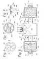
- FIG. 1is a perspective view of an isolation apparatus for a pod constructed in accordance with the preferred embodiment of the invention
- FIG. 2is a perspective view looking at the head end of the isolation apparatus of FIG. 1;
- FIG. 3is a view with the isolation apparatus of FIG. 1 open to expose the glove ports and the pass-through tubes and the interior of the isolation pod;
- FIG. 3Ais a fragmentary, cross-sectional view showing reinforcing straps at the bottom of the pad
- FIG. 4is a perspective view of the air purifier device used at the exhaust end for exhausting air from the isolation pod;
- FIG. 5is an enlarged, cross-sectional view taken along the line 5 — 5 of FIG. 4;
- FIG. 6is a plan view of a one way valve
- FIG. 7is a cross-sectional view of the one way valve of FIG. 6;
- FIG. 8is a cross-sectional view taken along the line 8 — 8 of FIG. 6;
- FIG. 9is an isometric view of the air purifier device for connection to the inlet port of the isolation pod
- FIG. 10is a plan view of the air purifier device of FIG. 9;
- FIG. 11is a cross-sectional view taken substantially along the line 11 — 11 of FIG. 10;
- FIG. 12is a cross-sectional view taken substantially along the line 12 — 12 of FIG. 10;
- FIG. 13is a cross-sectional view which illustrates restraint straps within the isolation pod
- FIG. 14illustrates a glove port and glove sleeve constructed in accordance with one embodiment of the invention
- FIG. 15is a cross-sectional view taken substantially along the line 15 — 15 of FIG. 14;
- FIG. 16is an elevational view of the pass-through sleeves on the interior and exterior of the isolation pod wall
- FIG. 17is a cross-sectional view taken substantially along the line 17 — 17 of FIG. 16;
- FIG. 18is a cross-sectional view taken along the line 18 — 18 of FIG. 16;
- FIG. 19is an elevational view which illustrates the severing of an exterior end of the pass-through tube
- FIG. 20is an elevational view which shows the sealing of the exterior end of the exterior sleeve of the pass-through and the severing of the interior end of the interior sleeve;
- FIG. 21is an elevational view which illustrates the sealing of the interior sleeve after the article has been passed through into the interior of the isolation pod;
- FIG. 22is a cross-sectional view of a sleeve used for catheters or the like.
- FIG. 23is a cross-sectional view which illustrates a catheter tube inserted through the sleeve of FIG. 22 with the sleeve sealed about the catheter tube;
- FIG. 24is a perspective view which illustrates a cover for the pass-through port
- FIG. 25is a perspective view showing covers being opened to allow access to the glove port
- FIG. 26is a perspective view which illustrates the collapsing of the isolation pod of FIGS. 1 and 2 and the insertion thereof into a carrier;
- FIG. 27is a perspective view which shows a threaded hose connection for an air hose used with the isolation apparatus jacket for ambulatory patients, shown in FIG. 28 .
- FIG. 28is a perspective view of a protective isolation apparatus used with a patient who is ambulatory.
- FIG. 29is a rear view of the ambulatory isolation device of FIG. 28 .
- FIG. 30is a cross-sectional view illustrating an adhesive tape connection at the waist of the jacket isolation device of FIGS. 28 and 29.
- FIG. 31is a cross-sectional view showing a layer of an adhesive type to the patient's waist and the use of a drawstring to seal the lower end of the jacket isolation to the patient's waist.
- FIG. 1an isolation pod or apparatus 10 without having a flexible cover or housing wall 14 and in FIG. 2 is another embodiment of the invention having a transparent housing wall 14 and a flexible base 12 or drag bottom attached to the bottom of the housing wall 14 .
- the housing wall 14 or 14 ais an airtight barrier wall to the passage of contaminants into or from the hollow interior of this isolation pod in which the patient is located.
- the drag bottom 12was integrally attached to and was part of the housing wall 14 .
- the base 12When used as a drag bottom, the base 12 is reinforced or made of a heavier material than the material of the housing wall; and a reinforced base is only or principally used as a drag bottom for dragging the pod 10 with a person in it in the field by the military. For many civilian uses and to reduce cost it is possible to provide an isolation apparatus 10 without the base attached thereto or to have a detachable drag bottom base 12 .
- the isolation apparatusis in the form of a jacket or housing having a housing or barrier wall 14 a which covers the upper torso and head and arms of an ambulatory patient.
- the transparent housing wall 14which is shown in FIG. 1, and the housing wall 14 a , which is shown in FIG.
- the barrier wall 14could be made of opaque and of composite materials other than the plastic sheet material described herein. If the barrier wall is opaque, then transparent windows will be provided therein to view the patient.
- a torso silhouette 13at least at the head end to show a visible reminder to whomever is placing patients into the isolation pod the proper orientation of the patient within the pod. It should be remembered that the placing of patients into such isolation pods may be done under extreme duress, such as in battlefield conditions or terrorist attacks, and may not always be done by trained medical personnel but by others who are untrained and are pressed into duty because of an emergency.
- the illustrated silhouette 13is merely a printed or painted silhouette of a patent's head and arms and torso at the top portion of the isolation pod on the lower clam shell half 30 .
- the illustrated halves of the isolation podopen like a sleeping bag with three sides having a zipper 20 and the fourth long side without a zipper.
- the zippercould be extended around the fourth side to allow the halves to separate from one another; and later be joined by the zipper 20 at time of usage of the pod.
- a restraintsuch as an upper belt 40 including a first half 44 and a second half 46 as well as a second lower belt 42 having a first half 48 and a second half 50 , as shown in FIG. 3 .
- These belts 40 and 42are attached to reinforcing webs 31 , 31 a and 31 b , which are described hereinafter.
- the basebe provided with a cap drain 54 at one or both lower corners from which fluids may be drained from the interior of the pod when it is raised.
- fluidsmay be decontamination fluids put into the housing pod by the medical personnel or may be contaminated fluids generated by the patients themselves.
- the housing wall 14 material of thin PVCis generally not sufficient in strength to support the patient without the base drag sheet.
- a patientstill may be transported by the use of selectively positioned reinforcing webs or straps (FIG. 3A) which are spaced along the pod and which are secured to the bottom layer of the bottom portion or half 30 of the clam shell. More specifically, at least three such webs, one web 31 at the shoulders, another web 31 a at the hips and a third web 31 b at the calves or feet, are supplied.
- the webshave particular handholds therein, as best seen in FIG.
- the drag sheetmay be made of various materials and may be attached to the housing as by being integrally attached as in the aforesaid copending application or detachably attached thereto, as illustrated and described herein.
- the preferred attachmentis made by simple pressure attachment devices such as a simple snap or clip 82 to provide a rapid connection which is readily understood by most people and which allows easy detachment of the base from the housing wall.
- the detachable drag bottom baseis formed of a thicker material and can be of a different material, such as a nylon or a heavy, thicker PVC plastic material, if desired.
- the baseand particularly when it is a drag bottom, may have a plurality of rectangular hand holds or openings 56 into which a person's hands may be inserted and used to pick up the pod without having any supporting structure underneath it.
- the basemay be provided as disclosed in the aforesaid application with grommets and tension members for engaging the grommets to allow overlapping of the base edges to be wrapped around a stretcher or litter to attach the pod securely to the stretcher for transport, as described in the aforesaid application.
- the isolation podmay have its own poles 83 (FIGS. 1 and 2) for attachment thereto. The isolation and treatment pod 10 can be used with various litter systems.
- collapsible pod 10have bendable, semi-rigid, arcuate stays or ribs 79 which act as support to keep the upper clam shell half of the housing wall 14 in a generally open expanded position about the patient prior to pressurization of the pod.
- the stays 79are preferably plastic ribs which are heat sealed to the plastic wall 14 or can be inserted into a sleeve 80 in the form of a hollow strip or channel of plastic secured to the housing wall 14 .
- the strips and staysmay be formed, such as shown in the aforesaid copending application, where the sleeve forms a channel to receive the stay along the outside of the pod with an entryway formed in the bottom thereof to receive the stay.
- the upper clam shell halfmay have the stays inserted into these sleeves to erect the upper clam shell half in the field at the time of usage of the pod.
- a plurality of small ports 87such as those shown in FIGS. 1, 2 and shown in enlarged detail in FIGS. 22 and 23.
- the ports 87are formed in the housing wall 14 and are normally provided with a tubular wall 88 having a closed end 89 and a hollow interior 88 a with the closed end 89 either being clipped off or perforated as at 88 b (FIG. 23) to allow a tube or line 91 to be inserted into the hollow interior and across the housing wall 14 in which the port opening is formed.
- the ports 87are spaced along the barrier housing wall 14 and are used for EKG apparatus lines, oxygen lines, intravenous lines, defibrillator lines, suction lines or the like.
- these small ports 87are positioned in the lower half 30 of the pod so that the lines or leads may stay connected to the patient whether the pod is in the open or closed position.
- the small portsmay be closed with various port clips or such as the O-ring 90 shown in FIG. 23 encircling the sleeve as well as the intravenous tube 91 . It is preferred that the port tubular wall 88 be encircled and closed against the tube or lead either by clips or other devices both prior to insertion of a intravenous tube or a lead and after the line or lead is therein, as shown in FIG. 23 .
- These small ports 87are usually positioned about the head area in the pod to allow suction lines or oxygen lines to be delivered to the head and about the chest area in the pod for intravenous lines and EKG lines. Other small ports may be provided where needed
- the pass-through 110includes a pair of hollow sleeves 115 and 116 with the outer exterior sleeve 115 having a hollow interior 115 b connected to and aligned with a hollow interior 116 b in the lower interior sleeve 116 shown in FIGS. 16 .
- An article 113may be passed through severed end 115 a of the exterior sleeve 115 after it has been cut by a severing device 117 or the like which opens the hollow interior of the sleeve 115 to allow the insertion of the article therein which is then passed by the barrier wall 14 to the interior of the interior sleeve 116 .
- the opened upper end of the sleeve 115is closed by a sealing unit 118 which could be a heat seal or could be a mechanical clip or tie.
- the outer sleeve 115is sealed so that there is no ingress or egress of air and air borne contamination through the previously opened end 115 a.
- Pass-through ports 110may be used to pass plastic bags containing objects through one at a time without breaching the containment of the pod.
- one of the pass-through ports 110near the head or the chest of the person where typically the medical personnel will be examining the head or chest of the patient, the patient's mouth and throat as well as the eyes of the patient and be using various instruments such as a stethoscope on the chest of the patient.
- the illustrated and preferred embodiment of the invention shown in FIG. 3is provided with four sets of glove ports, generally designated as 150 .
- the number and location of the glove ports 150may be varied from that illustrated in FIG. 3 where four pairs of glove ports are illustrated about the head, chest, waist and ankle locations of the patient.
- each pair of glove portsWhen looking down on a patient within the pod, each pair of glove ports will have one glove of the pair on the right side of the patient and the other of the glove pair on the left side of the patient.
- the respective right and left gloves 160 of each pairare aligned laterally opposite one another, as best seen in FIG. 3 .
- glove ports 150 a and 150 bthere are a pair of head area, glove ports 150 a and 150 b , a pair of chest area, glove ports 150 c and 150 d , a pair of waist or stomach area, glove ports 150 e and 150 f , and a pair of ankle or feet area, glove ports 150 g and 150 h .
- the glove ports positioncan be changed from that illustrated and described herein.
- Each of the glove ports 150includes a glove 160 , as best seen in FIG. 14, which may be a substantially ambidextrous, impermeable, chemical-resistance glove.
- Glove 160is connected to a glove port sleeve 162 which extends to a glove port opening 164 (FIG. 14) formed in the barrier wall 14 .
- the sleeve 162is hollow and long to receive the wrist and lower portion of an arm of a medical person treating the patient.
- the glove 60is detachably connected to the sleeve 162 by a connection device 166 which includes a hollow, stiff, plastic sleeve portion 168 which is attached as by adhesive or otherwise to the distal end of sleeve 162 .
- the glovehas an upper end 160 a which encircles and covers the lower end of the sleeve and is secured by a pair of O-rings 163 and 165 .
- the O-ringsclamp the upper end 160 a of the glove to a lower end of the sleeve 168 in an airtight manner.
- the rigid hollow sleeve 168 and the O-rings 165 and 163serve to provide a detachable interconnection between the gloves and the sleeve 162 .
- a suitable glove cover or closure 166is provided to close the opening 164 in the barrier wall 14 leading to the hollow interior in the sleeve 162 and the glove 160 until it is desired to have the caregiver insert his hand or arm into the glove port 150 .
- the illustrated glove port cover 166may take various forms and was described in the aforesaid copending application as including an airtight zipper type closure.
- the glove port cover 166is preferably, as best seen in FIGS. 24 and 25, provided with three cover flaps including a pair of slide flaps 171 and 172 formed of the same plastic material and attached at their upper ends to the sidewall 14 .
- An overhead and outer central flap 170overlies the other two flaps 171 and 172 and is secured to the barrier sidewall 14 .
- the flapsdrape downwardly by gravity to cover one another and to form a seal or cover, such as shown in FIG.
- the overlying central flap 170is seen overlying the abutted, inner edges 174 of the respective flaps 171 and 172 to cover and seal the glove port opening 164 against filling with decontamination fluids, which will typically be a decontamination liquid being used to wash down the exterior wall 14 of the pod 10 .
- the glove port coverprevents material from falling into the open glove port arm during transportation or the like of the patient or storage of the pod.
- the glove portmay be used to manipulate the patient within the pod without breaking the airtight barrier and releasing contaminants from the pod 10 into the environment or allowing contaminants from the environment to reach into the interior of the pod and to the patient.
- drain ports 94are provided at the lower outer foot end of the pod 10 through which liquids may be drained via gravity when tilting the pod with the patient inside the pod to cause the flow to the lower outer ends of the pod.
- the drain portsmay be normally closed by threaded gaps which may be unscrewed threaded nipples in the barrier wall which are desired to allow drainage. After drainage the drain ports 94 and 94 a may be closed by the threaded caps.
- the patientis provided with an air flow of a predetermined rate such as 4-6 cm cfm at a pressure of 4 inches of water to prevent a buildup of carbon dioxide about the patient's head and to remove moisture that would fog the interior of the plastic housing wall 14 , thereby interfering with the patient's view and also interfering with the view of the medical personnel observing the patient within the pod.
- a predetermined ratesuch as 4-6 cm cfm at a pressure of 4 inches of water
- the tightness of the housing wall 14 and the dynamics of the air floware such that the air leakage is kept within a predetermined range.
- the podwill meet the desired air tightness standard that not more than 20% of the air leaking from the housing pod over a five-minute period after the stopping of the air flow into the housing pod.
- the pressurized air flowalso expands the plastic housing wall in addition to the ribs 79 which are expanding the housing wall to keep it from touching the patient and particularly from touching any wounds the patient may have.
- the apparatusincludes an airtight closure or zipper device, such as that made by YKK of Japan. Unidirectional air flow valves at the air inlet and exhaust ports prevent air outflow through either of these ports.
- the airbe purified or filtered prior to flow into the containment pod 10 and also prior to being exhausted from the pod into the ambient atmosphere.
- the medical personnelmay be unsure or make a mistake as to which air is to be purified, that is, whether the ambient air is contaminated and needs to be purified or the atmosphere within the containment device is contaminated and needs to be purified.
- an air purifier device 200FIGGS. 1 and 2 which blows air which has been filtered by passing through a Class 1 type of filter and this filtered air is delivered through a hose 201 into the interior of the housing through a ventilation port 203 (FIG.
- the air entering the pod 10generally at or adjacent the head of the patient to sweep across the patient's head so that the patient feels less claustrophobic.
- a good air sweepis provided to assist the patient in breathing.
- airis extracted through a ventilation port 205 connected to a hose 207 leading to an exhaust purification or filtering device 210 which purifies and filters the air leaving the isolation pod 10 .
- the exhaust purifying device 210it is illustrated in greater detail in FIGS. 4-8 and comprises a filter housing 220 of rigid plastic which provides a hollow interior, large chamber 222 of a large volume relative to the hose 207 and the air passages within a one way air valve 224 at the inlet to the large chamber 222 .
- the large chamberis used because it does not restrict the flow of air or constrain the air so that the desired throughput and low back pressure is maintained despite a restricted flow of air across the one way air valve 224 and the filters 235 and 236 which are located in a hollow bore in a cylindrical wall 226 of the filter housing 220 .
- the outer end of the hose 207is attached to the cylindrical housing wall 207 .
- each of the filter devices 235 and 236has an interior filter material 240 which may include carbon and other materials needed to purify the air by filtering out contaminants or by a chemical reaction.
- the filtered airexits from the exhaust port screens 241 at smaller diameter, outlet ends 242 of the respective filter devices 235 and 236 .
- the illustrated filter devicesare commercially available filter devices made by several safety product companies and they are shown being used in the reverse manner because they are usually used with the inlet air flowing through the small diameter ends 242 and with the air exiting the large diameter housing end 232 .
- the pair of exhaust air filters 235 and 236are each connected to the filter housing 220 by a soft, flexible member or connector 239 that has a large diameter sleeve 241 which is telescoped over the respective rigid cylindrical walls 235 a and 236 a of the respective filters 235 and 236 .
- the intimate contact between the sleeve 241 and these cylindrical walls 235 a and 236 aprevents air leakage or any contaminant leakage and physically joins the filters to these outer, large diameter sleeves 241 of the respective connectors 239 .
- the flexible sleeve 241fits over the filter cannister and it has integrally molded small diameter ends 250 which fit over the exit ports 227 and 228 on the exit filter box housing 220 .
- each of the connectorshas a small diameter sleeve 250 that telescopes over the small diameter, cylindrical outlets 227 and 228 of the rigid plastic, filter housing 220 .
- These soft, small diameter sleeves 250are telescoped over the outlets 227 and 228 .
- Suitable hose clamps 254encircle the soft pliable plastic sleeves 250 and force them tightly against the respective rigid housing outlets 227 and 228 to prevent air or contaminant leakage.
- the illustrated one way valveis formed of plastic and comprises a hard rigid plastic housing portion or body with a central cone 262 and six spider or arms 264 which extend outwardly from an inner ring 262 a at the base of the pin 262 .
- a ring 267 of hard plasticjoining the ends of the spider arms 264 .
- Secured to the plastic ring 267are six diaphragm leaves or flaps 266 of soft, bendable plastic.
- Each of the leaves 266has its radially outer end 266 a secured to the outer rigid ring 267 with the interior small portions 266 b of the leaves 266 being flexible and pliable to be flexed outwardly by the air flow and the pressure of the outflowing air flowing in the direction of the arrows through an opening 268 , as best seen in FIG. 8 .
- the leaves and ends 266 b thereofare pushed downwardly with their inner ends 266 b resting against the ring 262 a and there is no bending past the ring in the opposite direction thereby closing off any air flow past the leaves 266 .
- the valve described and illustrated hereinis one embodiment of the invention and other checked valves or other valves may be used from that illustrated and described herein.
- the same one way air valve 224is also used with the air inlet purifier device 200 which is shown in FIGS. 9-12.
- the valve 224has its pin 262 within the interior hollow chamber 280 of a rigid filter housing 282 with the air flow bending the valve leaves 266 to allow air flow in the direction of the arrows shown in FIG. 12 . Reverse flow is not permitted by the valve 224 .
- the illustrated inlet air purifier and blower device 200includes a blower motor 290 which has a shaft 291 for rotating fan blades 292 to drive the air in the direction of the arrows past the one way valve and into the hose 201 which is connected to the ventilation port at the head end of the pod 10 .
- the air purifier device 200has a pair of filter devices 232 (FIG. 10) which are identical to the air filter devices 235 and 236 used at the exhaust end and previously described. The only difference is that the direction of the air is opposite with the air flow coming through the small diameter portions 241 and then flowing into the filter material 240 and through this filter material to exit the large diameter end of the filter into the interior hollow chamber 280 in which is housed the blower for driving the air.
- the preferred housing 280is generally triangular in shape with the pair of filter units 232 being upright cylinders at one end and with the hose 201 being connected by a threaded hose coupling 295 (FIG. 10) to the housing adjacent a narrow outlet end 296 .
- the isolation apparatuscomprises a jacket type of barrier wall 14 a that has a hood or head covering 300 that encloses the head of the patient and also has attached airtight gloves 302 .
- an airtight closure 304 in the form of an airtight zipper 306is provided in the back of jacket wall 14 a with the zipper extending from the top of the hood down to the lower end of the jacket which is at the waist of the patient. It is preferred to provide the zipper at the back so that the patient is not able to open the zipper by himself.
- the jacket wall 14 ais made of the same thin, flexible plastic such as a polyvinyl chloride in the range of less than 0.020 inch thick or less.
- a polyvinyl chloridein the range of less than 0.020 inch thick or less.
- the jacket wallexpands to keep most of the jacket off of the patient's body and any wounds the patient may have.
- the expansion of the hood 300 by the air pressure of the confined airallows the patient to see more clearly with the plastic wall 14 a being spaced from the patient's face.
- the inlet purified airis provided by the inlet air blower unit 200 of FIGS. 9-12 and the exhaust air leaving through hose 318 is directed into the air purifier unit 210 (FIGS.
- the preferred air flowis 4-6 cfm at a pressure of about 4 inches of water, as described above, to prevent carbon dioxide build-up to excessive levels and to keep the plastic housing from fogging and interfering with the patient's view.
- a jacket end closure 325is used at the patient's waist to prevent ingress or egress of contaminants.
- the jacket end closure 325comprises an adhesive tape 327 that adheres to the skin 329 of the patient at the patient's waist.
- the adhesive tape closure 325encircle the patient's waist and be adhered in airtight contact with the skin at the patient's waist.
- the adhesive tape closure 325is attached to a lower end 330 of the jacket isolation pod along an interior edge thereof.
- the attachmentis by means of adhesive layer 332 (FIGS. 30 and 31) which is on one side of a carrier layer or substrate 334 .
- the adhesive layer 327which adheres to the patient's skin, is on the other side of the carrier substrate 334 .
- a protective, peelable inner strip or layer 336is adhered to the patient adhesive layer 327 until the time of usage when the peelable strip 336 is removed exposing the adhesive layer 327 for attachment to the patient's skin.
- the adhesive tape 327comprises a series of thin, flexible, pliable layers 336 , 327 , 334 and 332 .
- the jacket closure 327preferably includes a drawstring 340 encircling the patient's waist to draw the lower end 330 of the jacket plastic wall 14 a against the patient's waist and to hold the jacket wall physically against the patient's waist and to resist forces that would tend to pull free the adhesive layer 327 from the patient's skin during the patient's treatment or ambulation.
- the adhesive layershould adhere sufficiently that it does not come loose during usage of the jacket isolation pod; but yet, can be stripped from the patient's skin without tearing the patient's skin and causing a high degree of pain.
- the jacket isolation pod 10 amay be collapsed and it is preferred that the air inlet and air exhaust purifier units 200 and 210 are separated from jacket wall 14 a when the jacket barrier wall 14 a is collapsed. It is preferred to have a pair of threaded nipples or connectors 350 (FIGS. 27 and 28) mounted on the jacket barrier wall 14 a at the patient's shoulder or chest area for connection to the respective air inlet hose 314 and air outlet hose 316 . Each of these hoses has a rotatable male, threaded connector 352 on the ends of the hoses for threading onto the threaded nipples 350 when the isolation pod 10 a is to be used.
- an inexpensive isolation podthat is readily transportable such as on a litter in FIGS. 1 and 2 or by ambulatory patient in FIGS. 28 and 29.
- the isolation podis useable for evacuation of battlefield casualties from a biological or chemical attack in that it is readily used with litters and litter poles.
- the barrier wall 14 or 14 amay be provided with glove ports, pass-through ports and other small ports for IV tubes, instrument leads, etc.
- the isolation pods 10 and 10 arequire attached purifier or filtering units that are portable and are relatively small and light in weight.
- isolation podsare inexpensive in that they are made with thin, flexible materials and provide soft walls that are collapsible to be stored in a relatively small volume. While the barrier walls 14 and 14 a have been described as being made of plastic in the illustrated embodiments of the invention, the soft barrier walls 14 or 14 a may be made of composite or laminated materials having layers of different materials and permeabilities. It will be appreciated that barrier wall 14 or 14 a could be made of opaque material with transparent plastic windows therein rather than being entirely transparent plastic, as in the illustrated embodiments described herein. While the stays used herein are preassembled to keep the upper covering portion spaced from the patient, the stay system for this upper covering portion could be assembled in the field at the time of usage of the isolation pod. A full length zipper allows easy entry and exit for the patient.
- the present inventionmay also be incorporated into wraps for civilian use in scenarios involving a limited number of pods for contaminated patients such as might be present in a chemical incident or for persons who would need to have medical attention administered through the wrap.
- suitsmay be provided including a power respirator hood that creates negative pressure within the hood and including rib or other supports for supporting the suit in particular the hood away from the person when the suit is being run in a negative pressure mode to prevent the suit from collapsing around the person.
Landscapes
- Health & Medical Sciences (AREA)
- Pulmonology (AREA)
- General Health & Medical Sciences (AREA)
- Business, Economics & Management (AREA)
- Emergency Management (AREA)
- Life Sciences & Earth Sciences (AREA)
- Animal Behavior & Ethology (AREA)
- Public Health (AREA)
- Veterinary Medicine (AREA)
- Accommodation For Nursing Or Treatment Tables (AREA)
Abstract
Description
Claims (50)
Priority Applications (4)
| Application Number | Priority Date | Filing Date | Title |
|---|---|---|---|
| US09/660,432US6461290B1 (en) | 1998-12-21 | 2000-09-12 | Collapsible isolation apparatus |
| PCT/US2001/041843WO2002022069A1 (en) | 2000-09-12 | 2001-08-23 | Collapsible isolation apparatus |
| AU2001293213AAU2001293213A1 (en) | 2000-09-12 | 2001-08-23 | Collapsible isolation apparatus |
| TW090121143ATW514522B (en) | 2000-09-12 | 2001-08-28 | Collapsible isolation apparatus |
Applications Claiming Priority (3)
| Application Number | Priority Date | Filing Date | Title |
|---|---|---|---|
| US11350398P | 1998-12-21 | 1998-12-21 | |
| US09/379,962US6321764B1 (en) | 1998-12-21 | 1999-08-24 | Collapsible isolation apparatus |
| US09/660,432US6461290B1 (en) | 1998-12-21 | 2000-09-12 | Collapsible isolation apparatus |
Related Parent Applications (1)
| Application Number | Title | Priority Date | Filing Date |
|---|---|---|---|
| US09/379,962Continuation-In-PartUS6321764B1 (en) | 1998-12-21 | 1999-08-24 | Collapsible isolation apparatus |
Publications (1)
| Publication Number | Publication Date |
|---|---|
| US6461290B1true US6461290B1 (en) | 2002-10-08 |
Family
ID=24649509
Family Applications (1)
| Application Number | Title | Priority Date | Filing Date |
|---|---|---|---|
| US09/660,432Expired - Fee RelatedUS6461290B1 (en) | 1998-12-21 | 2000-09-12 | Collapsible isolation apparatus |
Country Status (4)
| Country | Link |
|---|---|
| US (1) | US6461290B1 (en) |
| AU (1) | AU2001293213A1 (en) |
| TW (1) | TW514522B (en) |
| WO (1) | WO2002022069A1 (en) |
Cited By (70)
| Publication number | Priority date | Publication date | Assignee | Title |
|---|---|---|---|---|
| US20020112754A1 (en)* | 1998-12-21 | 2002-08-22 | Iit Research Institute | Collapsible isolation apparatus |
| US20020129563A1 (en)* | 2001-01-18 | 2002-09-19 | Martyn Ryder | Containment assembly |
| US20040111008A1 (en)* | 2002-12-09 | 2004-06-10 | Deano Perlatti | Isolation chamber |
| US20040111007A1 (en)* | 2002-12-09 | 2004-06-10 | Deano Perlatti | Isolation chamber |
| WO2004050001A2 (en) | 2002-11-27 | 2004-06-17 | Kappler Inc | Transportable contaminated remains pouch |
| EP1488772A2 (en) | 2003-06-20 | 2004-12-22 | Alion Science and Technology | Collapsible, protective containment device |
| US20050011006A1 (en)* | 2001-11-14 | 2005-01-20 | Ellen Thomas D. | Restraining enclosure for a bed and related method |
| EP1523973A2 (en) | 2003-10-17 | 2005-04-20 | Chi Yee Michael Yuen | Protective means and apparatus |
| US20060041994A1 (en)* | 2004-08-27 | 2006-03-02 | University Service Corporation Llc | Inflatable protective enclosure |
| US20060247487A1 (en)* | 2005-04-12 | 2006-11-02 | Arts Theodore A | Apparatus and method for providing continuous access to an isolation space while maintaining isolation |
| US20070056593A1 (en)* | 2005-06-13 | 2007-03-15 | Tvi Corporation | Collapsible patient isolation pod |
| US20070102005A1 (en)* | 2001-08-28 | 2007-05-10 | Bonutti Peter M | Surgical draping system |
| US7235066B1 (en)* | 2003-01-02 | 2007-06-26 | Newmedical Technology, Inc. | Fluid containment device |
| US20070199143A1 (en)* | 2006-02-27 | 2007-08-30 | Cunningham Angeline M | Shower curtain |
| US20080142060A1 (en)* | 2006-08-30 | 2008-06-19 | The North Face Apparel Corp. | Outdoor gear performance and trip management system |
| US20080219642A1 (en)* | 2007-03-09 | 2008-09-11 | Haitham Matloub | Collapsible Fluid Containment Device With Semi-Rigid Support Members |
| US20090093671A1 (en)* | 2007-10-04 | 2009-04-09 | Maloney Raymond C | Contamination detainment unit |
| WO2009109055A1 (en)* | 2008-03-04 | 2009-09-11 | Medaxis Ag | Protective tent |
| US20100138999A1 (en)* | 2008-12-10 | 2010-06-10 | Westmoreland Ii Ted Carson | Collapsible litter apparatus, system and method |
| US8007351B1 (en)* | 2005-05-16 | 2011-08-30 | Maloney Raymond C | Mobile personnel bio isolation device and method for protecting the interior of an ambulance from contamination |
| US20120117730A1 (en)* | 2006-06-28 | 2012-05-17 | Stryker Corporation | Patient support with wireless data and/or energy transfer |
| US8276223B1 (en) | 2009-09-10 | 2012-10-02 | Medibotics | Sleeping enclosure with assured ventilation |
| US20120298114A1 (en)* | 2011-05-26 | 2012-11-29 | Carefusion 2200, Inc. | Wound dressing system |
| US8407835B1 (en) | 2009-09-10 | 2013-04-02 | Medibotics Llc | Configuration-changing sleeping enclosure |
| US20140023469A1 (en)* | 2009-10-02 | 2014-01-23 | Stryker Corporation | Ambulance cot and loading and unloading system |
| WO2016012792A1 (en)* | 2014-07-24 | 2016-01-28 | Howorth Air Technology Limited | A modular enclosure |
| WO2016073375A1 (en)* | 2014-11-03 | 2016-05-12 | Magbee David Scott | A protective covering for a patient |
| US20180160819A1 (en)* | 2016-12-12 | 2018-06-14 | Helene F. RUTLEDGE | Sleep pod with controlled environment |
| KR101902488B1 (en) | 2017-04-17 | 2018-10-01 | (주)에어박스 | an isolation apparatus for patient |
| USD829884S1 (en)* | 2015-11-16 | 2018-10-02 | Epiguard As | Patient isolator |
| CN111195181A (en)* | 2020-02-25 | 2020-05-26 | 吉林大学 | Novel device for preventing coronaviruses from splashing and reducing virus aerosol diffusion |
| KR102160896B1 (en)* | 2020-04-21 | 2020-09-28 | 이명식 | Sound pressure bag for patient transportation |
| KR102160895B1 (en)* | 2020-04-21 | 2020-09-28 | 이명식 | Mobile sound pressure bag fixing device |
| US10806656B2 (en) | 2015-11-13 | 2020-10-20 | Oslo Universitetssykehus Hf | Patient isolator |
| US10888479B1 (en)* | 2020-06-05 | 2021-01-12 | Alan Gershon | Biosafety enclosure for occupants of vehicles |
| CN113081463A (en)* | 2021-04-15 | 2021-07-09 | 军事科学院系统工程研究院卫勤保障技术研究所 | Box-type physical cooling device |
| USD926994S1 (en)* | 2019-05-18 | 2021-08-03 | Surgibox Inc. | Enclosure system for isolation of surgical sites |
| US20210236366A1 (en)* | 2020-02-05 | 2021-08-05 | David Serrano | Personal micro-climate system for bedridden patients |
| WO2021189526A1 (en)* | 2020-03-27 | 2021-09-30 | 同济大学 | Pneumatic membrane structure virus test laboratory and earth-sheltered structure virus test laboratory |
| WO2021215586A1 (en)* | 2020-04-24 | 2021-10-28 | Industry-Academic Cooperation Foundation, Yonsei University | Patient tailored-installable negative pressure isolator |
| US20210338361A1 (en)* | 2020-05-01 | 2021-11-04 | Ibrahim Majzoub | Pathogen containment device |
| US11179285B2 (en)* | 2020-04-11 | 2021-11-23 | Ikonx Incorporated | Patient airway dome and methods of making and using same |
| WO2021236438A1 (en)* | 2020-05-21 | 2021-11-25 | Aerosol Containment Container, LLC | Aerosol containment enclosure |
| US20210369397A1 (en)* | 2020-05-27 | 2021-12-02 | Robbie Slim | Device and method to protect medical professionals from pathogen-containing droplets while attending to patients |
| WO2021257321A1 (en)* | 2020-06-15 | 2021-12-23 | Numotech, Inc. | Isolation system |
| IT202000015724A1 (en)* | 2020-06-30 | 2021-12-30 | Olmedo Special Vehicles S P A | AMBULANCE AND SYSTEM FOR THE TRANSPORT OF A PATIENT |
| US20220000581A1 (en)* | 2020-07-06 | 2022-01-06 | Jonathan Nover | Anti-aerosolizing tent |
| WO2022016017A1 (en)* | 2020-07-15 | 2022-01-20 | S.W.O.R.D. International Inc. | Intubation infection control tent |
| US20220015860A1 (en)* | 2020-07-16 | 2022-01-20 | Buddhist Tzu Chi Medical Foundation | Method and article for protecting airway management procedures |
| US20220117817A1 (en)* | 2020-10-19 | 2022-04-21 | Junzo UCHIYAMA | Simplified examination room and simplified examination room assembly set |
| US11357686B2 (en)* | 2013-05-20 | 2022-06-14 | Breegi Scientific, Inc. | Deployable compact surgical and biological apparatus and methods of use |
| WO2022125605A1 (en)* | 2020-12-10 | 2022-06-16 | Flexsys Inc. | Respiratory pump arrangement for personal respiratory isolation and method of use |
| WO2022139197A1 (en)* | 2020-12-22 | 2022-06-30 | 한국과학기술원 | Patient transport device |
| US11400321B2 (en)* | 2020-07-02 | 2022-08-02 | SCONE Medical Solutions Inc. | Self-contained negative pressure environment device and system |
| US11406550B1 (en) | 2021-12-30 | 2022-08-09 | Aerosol Containment Container, LLC | Aerosol containment enclosure |
| US11439554B2 (en) | 2017-02-03 | 2022-09-13 | Breegi Scientific, Inc. | Disposable infant incubator and disposable contained microenvironment for stationary or transport cases |
| US20230015948A1 (en)* | 2020-05-12 | 2023-01-19 | Michael Bardo | Portable collapsible air isolation apparatus |
| US11564852B2 (en) | 2016-11-14 | 2023-01-31 | Christian DELISE | Mobile hyperbaric unit |
| US11564853B1 (en) | 2019-01-11 | 2023-01-31 | Christian DELISE | Hyperbaric vehicle and transfer under pressure (TUP) unit |
| US11571348B2 (en)* | 2015-11-05 | 2023-02-07 | Air Shelters USA, LLC | Medical isolation transport system—MITS |
| CN115887143A (en)* | 2022-12-09 | 2023-04-04 | 中国人民解放军海军特色医学中心 | Soft negative pressure cabin isolation system and rapid deployment method thereof |
| US20230248600A1 (en)* | 2020-09-16 | 2023-08-10 | The Regents Of The University Of Colorado, A Body Corporate | Ems-protect: patient-based reduction of transmitting emerging contagions tent |
| US20230329945A1 (en)* | 2022-04-15 | 2023-10-19 | Isovac Products Llc | Isolation apparatus |
| US20240115348A1 (en)* | 2022-10-11 | 2024-04-11 | Donald Robert Wallace | Device for Performing Sterile Invasive Medical Procedures That Facilitates Ultrasound Guidance During Procedures |
| USD1025494S1 (en)* | 2021-03-31 | 2024-04-30 | Aerosolshield Limited | Isolation apparatus |
| EP4135857A4 (en)* | 2020-04-17 | 2024-05-08 | General Electric Company | Patient isolation unit for pathogen containment during medical imaging procedures |
| US12115106B1 (en) | 2023-03-09 | 2024-10-15 | King Saud University | Aerosol box for protection during aerosol-generating procedures |
| US12156835B1 (en)* | 2023-07-07 | 2024-12-03 | Typhoon Water Wares Llc | Portable pressurized hyperbaric chamber |
| US12310897B2 (en) | 2020-04-03 | 2025-05-27 | The University Of Kansas | Negative pressure aerosolization mitigation devices and methods |
| US12414889B2 (en) | 2020-07-06 | 2025-09-16 | Lgi, Llc | Patient intubating partition sphere |
Families Citing this family (12)
| Publication number | Priority date | Publication date | Assignee | Title |
|---|---|---|---|---|
| DE10314890B3 (en)* | 2003-04-01 | 2004-08-19 | Autoflug Gmbh | Aircraft passenger isolation device using gas-tight sleeve sealed against aircraft cabin walls for providing sealed cell isolating at least one seated passenger from surrounding atmosphere |
| WO2005009316A1 (en)* | 2003-07-26 | 2005-02-03 | International Sos Pte Ltd | A collapsable portable isolator |
| WO2018170287A1 (en)* | 2017-03-15 | 2018-09-20 | Isovac Products Llc | Marine rescue patient isolation apparatus |
| RU183680U1 (en)* | 2017-11-21 | 2018-10-01 | федеральное государственное бюджетное образовательное учреждение высшего образования "Нижегородский государственный технический университет им. Р.Е. Алексеева" (НГТУ) | A device for treating burns in a controlled wet environment |
| CN110064143B (en)* | 2019-06-14 | 2024-02-20 | 广州市增城区林业和园林科学研究所(广州市增城区林业和园林技术推广中心) | Fire-fighting rescue capsule |
| CN111281710B (en)* | 2020-03-27 | 2024-08-06 | 珠海市优氧健康产业有限公司 | Portable negative pressure holographic disinfection isolation cabin |
| AU2021246544A1 (en)* | 2020-04-01 | 2022-12-01 | Creative Hinge Pty Ltd | Device for limiting infection |
| TWM599336U (en)* | 2020-05-13 | 2020-08-01 | 高昌生醫股份有限公司 | Negative pressure protection system |
| US11519168B2 (en)* | 2020-06-15 | 2022-12-06 | Teresa Nadolski | Vaccination guard system |
| TWI785704B (en)* | 2021-07-29 | 2022-12-01 | 長庚學校財團法人長庚科技大學 | glove machine |
| USD995792S1 (en) | 2021-11-27 | 2023-08-15 | Sphaira Medical Gmbh | Trolley for medical care |
| USD995793S1 (en) | 2021-11-27 | 2023-08-15 | Sphaira Medical Gmbh | Trolley for medical care |
Citations (25)
| Publication number | Priority date | Publication date | Assignee | Title |
|---|---|---|---|---|
| US2683262A (en) | 1951-02-19 | 1954-07-13 | Foss Bjorn | Protective cover |
| US2985129A (en) | 1957-01-28 | 1961-05-23 | Brooks & Perkins | Apparatus for performing operations in controlled atmosphere |
| US3118401A (en) | 1964-01-21 | Radiation protector | ||
| US3119358A (en) | 1961-11-06 | 1964-01-28 | Robert T Colson | Shelter |
| US3265059A (en) | 1962-02-21 | 1966-08-09 | Matthews Res Inc | Isolator assembly |
| US3272199A (en) | 1965-01-28 | 1966-09-13 | Matthews Res Inc | Process and assembly for enclosing a volume |
| US3695507A (en) | 1970-01-26 | 1972-10-03 | Ronald G Sams | Survival bag |
| US3766844A (en) | 1971-12-21 | 1973-10-23 | Us Army | Protective system for contaminated atmosphere |
| US3877427A (en)* | 1972-05-25 | 1975-04-15 | Semen Mikhailovich Alexeev | Oxygen compressive chamber |
| US4000749A (en) | 1975-05-30 | 1977-01-04 | Float | Isolation module |
| US4352991A (en) | 1981-05-04 | 1982-10-05 | Arthur Kaufman | Portable life support system |
| US4389066A (en) | 1980-11-07 | 1983-06-21 | Roy Weir | Rescue unit |
| US4584989A (en) | 1984-12-20 | 1986-04-29 | Rosemarie Stith | Life support stretcher bed |
| US4736762A (en) | 1985-12-16 | 1988-04-12 | Wayman Joseph R | Anti-contamination means |
| US5061235A (en)* | 1987-01-09 | 1991-10-29 | Beth Israel Hospital Association | Portable superabsorbant personnel stretcher and erectable on-demand isolation tent |
| US5255673A (en)* | 1989-01-27 | 1993-10-26 | Courtaulds Plc & Sos Limited | Pressure vessels |
| US5314377A (en) | 1992-10-05 | 1994-05-24 | Airo Clean Inc. | Clean air isolation enclosure |
| US5331991A (en) | 1991-11-15 | 1994-07-26 | Ab Ventilatorverken | Ventilation method and means for the same |
| US5582574A (en)* | 1995-03-24 | 1996-12-10 | Cramer; Frederick S. | Hyperbaric incubation method |
| US5626151A (en) | 1996-03-07 | 1997-05-06 | The United States Of America As Represented By The Secretary Of The Army | Transportable life support system |
| US5630296A (en) | 1994-08-25 | 1997-05-20 | Kendall, Jr.; Robert T. | Inflatable emergency shelter |
| US5725426A (en) | 1995-12-26 | 1998-03-10 | Alvarez; Henry | Portable and disposable sterilized operating environment |
| US5865722A (en)* | 1997-04-04 | 1999-02-02 | Numotech, Incorporated | Shape-adaptable topical hyperbaric oxygen chamber |
| US5950625A (en)* | 1997-12-09 | 1999-09-14 | Northrop Grumman Corporation | Isolation bag |
| US6241653B1 (en)* | 1999-07-16 | 2001-06-05 | Isovac Products Llc | Isolation apparatus |
- 2000
- 2000-09-12USUS09/660,432patent/US6461290B1/ennot_activeExpired - Fee Related
- 2001
- 2001-08-23WOPCT/US2001/041843patent/WO2002022069A1/enactiveApplication Filing
- 2001-08-23AUAU2001293213Apatent/AU2001293213A1/ennot_activeAbandoned
- 2001-08-28TWTW090121143Apatent/TW514522B/ennot_activeIP Right Cessation
Patent Citations (25)
| Publication number | Priority date | Publication date | Assignee | Title |
|---|---|---|---|---|
| US3118401A (en) | 1964-01-21 | Radiation protector | ||
| US2683262A (en) | 1951-02-19 | 1954-07-13 | Foss Bjorn | Protective cover |
| US2985129A (en) | 1957-01-28 | 1961-05-23 | Brooks & Perkins | Apparatus for performing operations in controlled atmosphere |
| US3119358A (en) | 1961-11-06 | 1964-01-28 | Robert T Colson | Shelter |
| US3265059A (en) | 1962-02-21 | 1966-08-09 | Matthews Res Inc | Isolator assembly |
| US3272199A (en) | 1965-01-28 | 1966-09-13 | Matthews Res Inc | Process and assembly for enclosing a volume |
| US3695507A (en) | 1970-01-26 | 1972-10-03 | Ronald G Sams | Survival bag |
| US3766844A (en) | 1971-12-21 | 1973-10-23 | Us Army | Protective system for contaminated atmosphere |
| US3877427A (en)* | 1972-05-25 | 1975-04-15 | Semen Mikhailovich Alexeev | Oxygen compressive chamber |
| US4000749A (en) | 1975-05-30 | 1977-01-04 | Float | Isolation module |
| US4389066A (en) | 1980-11-07 | 1983-06-21 | Roy Weir | Rescue unit |
| US4352991A (en) | 1981-05-04 | 1982-10-05 | Arthur Kaufman | Portable life support system |
| US4584989A (en) | 1984-12-20 | 1986-04-29 | Rosemarie Stith | Life support stretcher bed |
| US4736762A (en) | 1985-12-16 | 1988-04-12 | Wayman Joseph R | Anti-contamination means |
| US5061235A (en)* | 1987-01-09 | 1991-10-29 | Beth Israel Hospital Association | Portable superabsorbant personnel stretcher and erectable on-demand isolation tent |
| US5255673A (en)* | 1989-01-27 | 1993-10-26 | Courtaulds Plc & Sos Limited | Pressure vessels |
| US5331991A (en) | 1991-11-15 | 1994-07-26 | Ab Ventilatorverken | Ventilation method and means for the same |
| US5314377A (en) | 1992-10-05 | 1994-05-24 | Airo Clean Inc. | Clean air isolation enclosure |
| US5630296A (en) | 1994-08-25 | 1997-05-20 | Kendall, Jr.; Robert T. | Inflatable emergency shelter |
| US5582574A (en)* | 1995-03-24 | 1996-12-10 | Cramer; Frederick S. | Hyperbaric incubation method |
| US5725426A (en) | 1995-12-26 | 1998-03-10 | Alvarez; Henry | Portable and disposable sterilized operating environment |
| US5626151A (en) | 1996-03-07 | 1997-05-06 | The United States Of America As Represented By The Secretary Of The Army | Transportable life support system |
| US5865722A (en)* | 1997-04-04 | 1999-02-02 | Numotech, Incorporated | Shape-adaptable topical hyperbaric oxygen chamber |
| US5950625A (en)* | 1997-12-09 | 1999-09-14 | Northrop Grumman Corporation | Isolation bag |
| US6241653B1 (en)* | 1999-07-16 | 2001-06-05 | Isovac Products Llc | Isolation apparatus |
Cited By (111)
| Publication number | Priority date | Publication date | Assignee | Title |
|---|---|---|---|---|
| US20020112754A1 (en)* | 1998-12-21 | 2002-08-22 | Iit Research Institute | Collapsible isolation apparatus |
| US20020129563A1 (en)* | 2001-01-18 | 2002-09-19 | Martyn Ryder | Containment assembly |
| US7017306B2 (en)* | 2001-01-18 | 2006-03-28 | Carlisle Process Systems Limited | Containment assembly |
| US20070102005A1 (en)* | 2001-08-28 | 2007-05-10 | Bonutti Peter M | Surgical draping system |
| US20080047567A1 (en)* | 2001-08-28 | 2008-02-28 | Bonutti Peter M | Surgical draping system |
| US8739797B2 (en) | 2001-08-28 | 2014-06-03 | Bonutti Skeletal Innovations Llc | Surgical draping system |
| US7380296B2 (en) | 2001-11-14 | 2008-06-03 | Vival Medical Corporation | Restraining enclosure for a bed and related method |
| US20050011006A1 (en)* | 2001-11-14 | 2005-01-20 | Ellen Thomas D. | Restraining enclosure for a bed and related method |
| AU2010200068B2 (en)* | 2001-11-14 | 2011-12-22 | Vivax Medical Corporation | Portable isolation enclosure |
| US7479103B2 (en) | 2001-11-14 | 2009-01-20 | Vivax Medical Corporation | Portable isolation enclosure |
| WO2004050001A2 (en) | 2002-11-27 | 2004-06-17 | Kappler Inc | Transportable contaminated remains pouch |
| US7484275B2 (en) | 2002-11-27 | 2009-02-03 | Kappler, Inc. | Transportable contaminated remains pouch |
| US20090007402A1 (en)* | 2002-11-27 | 2009-01-08 | Carroll Todd R | Transportable contaminated remains pouch |
| US20040215051A1 (en)* | 2002-12-09 | 2004-10-28 | Deano Perlatti | Isolation chamber |
| US6971985B2 (en)* | 2002-12-09 | 2005-12-06 | Seattle Tarp Company | Isolation chamber |
| US6969346B2 (en) | 2002-12-09 | 2005-11-29 | Seattle Tarp Company | Isolation chamber |
| US20040111007A1 (en)* | 2002-12-09 | 2004-06-10 | Deano Perlatti | Isolation chamber |
| US20040111008A1 (en)* | 2002-12-09 | 2004-06-10 | Deano Perlatti | Isolation chamber |
| US7235066B1 (en)* | 2003-01-02 | 2007-06-26 | Newmedical Technology, Inc. | Fluid containment device |
| EP1488772A2 (en) | 2003-06-20 | 2004-12-22 | Alion Science and Technology | Collapsible, protective containment device |
| EP1523973A2 (en) | 2003-10-17 | 2005-04-20 | Chi Yee Michael Yuen | Protective means and apparatus |
| US20050085686A1 (en)* | 2003-10-17 | 2005-04-21 | Yuen Chi Yee M. | Protective means and apparatus |
| US20060041994A1 (en)* | 2004-08-27 | 2006-03-02 | University Service Corporation Llc | Inflatable protective enclosure |
| US7712151B2 (en) | 2004-08-27 | 2010-05-11 | Campus Housing Company LLC | Inflatable protective enclosure |
| EP1868554A4 (en)* | 2005-04-12 | 2008-12-17 | Theodore A M Arts | Apparatus and method for providing continuous access to an isolation space while maintaining isolation |
| US20060247487A1 (en)* | 2005-04-12 | 2006-11-02 | Arts Theodore A | Apparatus and method for providing continuous access to an isolation space while maintaining isolation |
| WO2006110797A3 (en)* | 2005-04-12 | 2007-07-12 | Theodore A M Arts | Apparatus and method for providing continuous access to an isolation space while maintaining isolation |
| US20100305393A1 (en)* | 2005-04-12 | 2010-12-02 | Charles K. Akers | Apparatus and method for providing continuous access to an isolation space while maintaining isolation |
| US7789820B2 (en)* | 2005-04-12 | 2010-09-07 | Charles K. Akers | Apparatus and method for providing continuous access to an isolation space while maintaining isolation |
| US8007351B1 (en)* | 2005-05-16 | 2011-08-30 | Maloney Raymond C | Mobile personnel bio isolation device and method for protecting the interior of an ambulance from contamination |
| US20070056593A1 (en)* | 2005-06-13 | 2007-03-15 | Tvi Corporation | Collapsible patient isolation pod |
| US7503890B2 (en)* | 2005-06-13 | 2009-03-17 | Tvi Corporation | Collapsible patient isolation pod |
| WO2006138232A3 (en)* | 2005-06-13 | 2009-05-07 | Tvi Corp | Collapsible patient isolation pod |
| US20070199143A1 (en)* | 2006-02-27 | 2007-08-30 | Cunningham Angeline M | Shower curtain |
| US8864205B2 (en)* | 2006-06-28 | 2014-10-21 | Stryker Corporation | Patient support with wireless data and/or energy transfer |
| US11793699B2 (en) | 2006-06-28 | 2023-10-24 | Stryker Corporation | Patient support with energy transfer |
| US12383450B2 (en) | 2006-06-28 | 2025-08-12 | Stryker Corporation | Patient support with energy transfer |
| US10561551B2 (en) | 2006-06-28 | 2020-02-18 | Stryker Corporation | Patient support with energy transfer |
| US20120117730A1 (en)* | 2006-06-28 | 2012-05-17 | Stryker Corporation | Patient support with wireless data and/or energy transfer |
| US20080142060A1 (en)* | 2006-08-30 | 2008-06-19 | The North Face Apparel Corp. | Outdoor gear performance and trip management system |
| US7716013B2 (en) | 2006-08-30 | 2010-05-11 | The North Face Apparel Corp. | Outdoor gear performance and trip management system |
| US20080219642A1 (en)* | 2007-03-09 | 2008-09-11 | Haitham Matloub | Collapsible Fluid Containment Device With Semi-Rigid Support Members |
| US7678092B2 (en)* | 2007-03-09 | 2010-03-16 | Haitham Matloub | Collapsible fluid containment device with semi-rigid support members |
| US20090093671A1 (en)* | 2007-10-04 | 2009-04-09 | Maloney Raymond C | Contamination detainment unit |
| US8298130B2 (en)* | 2007-10-04 | 2012-10-30 | Maloney Raymond C | Contamination detainment unit |
| WO2009109055A1 (en)* | 2008-03-04 | 2009-09-11 | Medaxis Ag | Protective tent |
| US8127381B2 (en) | 2008-12-10 | 2012-03-06 | Speer Operational Technologies, LLC | Collapsible litter apparatus, system and method |
| US20100138999A1 (en)* | 2008-12-10 | 2010-06-10 | Westmoreland Ii Ted Carson | Collapsible litter apparatus, system and method |
| US8276223B1 (en) | 2009-09-10 | 2012-10-02 | Medibotics | Sleeping enclosure with assured ventilation |
| US8407835B1 (en) | 2009-09-10 | 2013-04-02 | Medibotics Llc | Configuration-changing sleeping enclosure |
| US12357518B2 (en) | 2009-10-02 | 2025-07-15 | Stryker Corporation | Ambulance cot and loading and unloading system |
| US10806647B2 (en)* | 2009-10-02 | 2020-10-20 | Stryker Corporation | Ambulance cot and loading and unloading system |
| US9456939B2 (en) | 2009-10-02 | 2016-10-04 | Stryker Corporation | Ambulance cot and loading and unloading system |
| US20140023469A1 (en)* | 2009-10-02 | 2014-01-23 | Stryker Corporation | Ambulance cot and loading and unloading system |
| US8973963B2 (en)* | 2009-10-02 | 2015-03-10 | Stryker Corporation | Ambulance cot and loading and unloading system |
| US10149791B2 (en)* | 2009-10-02 | 2018-12-11 | Stryker Corporation | Ambulance cot and loading and unloading system |
| US20120298114A1 (en)* | 2011-05-26 | 2012-11-29 | Carefusion 2200, Inc. | Wound dressing system |
| US11357686B2 (en)* | 2013-05-20 | 2022-06-14 | Breegi Scientific, Inc. | Deployable compact surgical and biological apparatus and methods of use |
| WO2016012792A1 (en)* | 2014-07-24 | 2016-01-28 | Howorth Air Technology Limited | A modular enclosure |
| WO2016073375A1 (en)* | 2014-11-03 | 2016-05-12 | Magbee David Scott | A protective covering for a patient |
| US11571348B2 (en)* | 2015-11-05 | 2023-02-07 | Air Shelters USA, LLC | Medical isolation transport system—MITS |
| CN113057832B (en)* | 2015-11-13 | 2022-05-03 | 奥斯陆大学医院Hf | Patient isolator |
| US10806656B2 (en) | 2015-11-13 | 2020-10-20 | Oslo Universitetssykehus Hf | Patient isolator |
| CN113057832A (en)* | 2015-11-13 | 2021-07-02 | 奥斯陆大学医院Hf | patient isolator |
| USD829884S1 (en)* | 2015-11-16 | 2018-10-02 | Epiguard As | Patient isolator |
| USD884875S1 (en) | 2015-11-16 | 2020-05-19 | Epiguard As | Patient isolator |
| US11564852B2 (en) | 2016-11-14 | 2023-01-31 | Christian DELISE | Mobile hyperbaric unit |
| US20180160819A1 (en)* | 2016-12-12 | 2018-06-14 | Helene F. RUTLEDGE | Sleep pod with controlled environment |
| US11439554B2 (en) | 2017-02-03 | 2022-09-13 | Breegi Scientific, Inc. | Disposable infant incubator and disposable contained microenvironment for stationary or transport cases |
| KR101902488B1 (en) | 2017-04-17 | 2018-10-01 | (주)에어박스 | an isolation apparatus for patient |
| US11564853B1 (en) | 2019-01-11 | 2023-01-31 | Christian DELISE | Hyperbaric vehicle and transfer under pressure (TUP) unit |
| USD926994S1 (en)* | 2019-05-18 | 2021-08-03 | Surgibox Inc. | Enclosure system for isolation of surgical sites |
| US20210236366A1 (en)* | 2020-02-05 | 2021-08-05 | David Serrano | Personal micro-climate system for bedridden patients |
| CN111195181A (en)* | 2020-02-25 | 2020-05-26 | 吉林大学 | Novel device for preventing coronaviruses from splashing and reducing virus aerosol diffusion |
| WO2021189526A1 (en)* | 2020-03-27 | 2021-09-30 | 同济大学 | Pneumatic membrane structure virus test laboratory and earth-sheltered structure virus test laboratory |
| US12310897B2 (en) | 2020-04-03 | 2025-05-27 | The University Of Kansas | Negative pressure aerosolization mitigation devices and methods |
| US11179285B2 (en)* | 2020-04-11 | 2021-11-23 | Ikonx Incorporated | Patient airway dome and methods of making and using same |
| EP4135857A4 (en)* | 2020-04-17 | 2024-05-08 | General Electric Company | Patient isolation unit for pathogen containment during medical imaging procedures |
| KR102160896B1 (en)* | 2020-04-21 | 2020-09-28 | 이명식 | Sound pressure bag for patient transportation |
| KR102160895B1 (en)* | 2020-04-21 | 2020-09-28 | 이명식 | Mobile sound pressure bag fixing device |
| KR20210131774A (en)* | 2020-04-24 | 2021-11-03 | 연세대학교 산학협력단 | Patient tailored-installable negative pressure isolator |
| WO2021215586A1 (en)* | 2020-04-24 | 2021-10-28 | Industry-Academic Cooperation Foundation, Yonsei University | Patient tailored-installable negative pressure isolator |
| US20210338361A1 (en)* | 2020-05-01 | 2021-11-04 | Ibrahim Majzoub | Pathogen containment device |
| US11857465B2 (en)* | 2020-05-12 | 2024-01-02 | Michael Bardo | Portable collapsible air isolation apparatus |
| US20230015948A1 (en)* | 2020-05-12 | 2023-01-19 | Michael Bardo | Portable collapsible air isolation apparatus |
| US20240082090A1 (en)* | 2020-05-12 | 2024-03-14 | Michael Bardo | Portable collapsible air isolation apparatus |
| WO2021236438A1 (en)* | 2020-05-21 | 2021-11-25 | Aerosol Containment Container, LLC | Aerosol containment enclosure |
| US20210369397A1 (en)* | 2020-05-27 | 2021-12-02 | Robbie Slim | Device and method to protect medical professionals from pathogen-containing droplets while attending to patients |
| US10888479B1 (en)* | 2020-06-05 | 2021-01-12 | Alan Gershon | Biosafety enclosure for occupants of vehicles |
| US12186265B2 (en) | 2020-06-15 | 2025-01-07 | Numotech, Inc. | Isolation system |
| WO2021257321A1 (en)* | 2020-06-15 | 2021-12-23 | Numotech, Inc. | Isolation system |
| IT202000015724A1 (en)* | 2020-06-30 | 2021-12-30 | Olmedo Special Vehicles S P A | AMBULANCE AND SYSTEM FOR THE TRANSPORT OF A PATIENT |
| US11400321B2 (en)* | 2020-07-02 | 2022-08-02 | SCONE Medical Solutions Inc. | Self-contained negative pressure environment device and system |
| US12414889B2 (en) | 2020-07-06 | 2025-09-16 | Lgi, Llc | Patient intubating partition sphere |
| US20220000581A1 (en)* | 2020-07-06 | 2022-01-06 | Jonathan Nover | Anti-aerosolizing tent |
| WO2022016017A1 (en)* | 2020-07-15 | 2022-01-20 | S.W.O.R.D. International Inc. | Intubation infection control tent |
| US20220015860A1 (en)* | 2020-07-16 | 2022-01-20 | Buddhist Tzu Chi Medical Foundation | Method and article for protecting airway management procedures |
| US20230248600A1 (en)* | 2020-09-16 | 2023-08-10 | The Regents Of The University Of Colorado, A Body Corporate | Ems-protect: patient-based reduction of transmitting emerging contagions tent |
| US20220117817A1 (en)* | 2020-10-19 | 2022-04-21 | Junzo UCHIYAMA | Simplified examination room and simplified examination room assembly set |
| WO2022125605A1 (en)* | 2020-12-10 | 2022-06-16 | Flexsys Inc. | Respiratory pump arrangement for personal respiratory isolation and method of use |
| WO2022139197A1 (en)* | 2020-12-22 | 2022-06-30 | 한국과학기술원 | Patient transport device |
| USD1025494S1 (en)* | 2021-03-31 | 2024-04-30 | Aerosolshield Limited | Isolation apparatus |
| CN113081463B (en)* | 2021-04-15 | 2023-07-25 | 军事科学院系统工程研究院卫勤保障技术研究所 | Box-type physical cooling device |
| CN113081463A (en)* | 2021-04-15 | 2021-07-09 | 军事科学院系统工程研究院卫勤保障技术研究所 | Box-type physical cooling device |
| US11406550B1 (en) | 2021-12-30 | 2022-08-09 | Aerosol Containment Container, LLC | Aerosol containment enclosure |
| US11896532B2 (en)* | 2022-04-15 | 2024-02-13 | Isovac Products Llc | Isolation apparatus |
| US20230329945A1 (en)* | 2022-04-15 | 2023-10-19 | Isovac Products Llc | Isolation apparatus |
| US20240115348A1 (en)* | 2022-10-11 | 2024-04-11 | Donald Robert Wallace | Device for Performing Sterile Invasive Medical Procedures That Facilitates Ultrasound Guidance During Procedures |
| CN115887143A (en)* | 2022-12-09 | 2023-04-04 | 中国人民解放军海军特色医学中心 | Soft negative pressure cabin isolation system and rapid deployment method thereof |
| US12115106B1 (en) | 2023-03-09 | 2024-10-15 | King Saud University | Aerosol box for protection during aerosol-generating procedures |
| US12156835B1 (en)* | 2023-07-07 | 2024-12-03 | Typhoon Water Wares Llc | Portable pressurized hyperbaric chamber |
Also Published As
| Publication number | Publication date |
|---|---|
| WO2002022069A1 (en) | 2002-03-21 |
| TW514522B (en) | 2002-12-21 |
| AU2001293213A1 (en) | 2002-03-26 |
Similar Documents
| Publication | Publication Date | Title |
|---|---|---|
| US6461290B1 (en) | Collapsible isolation apparatus | |
| US6321764B1 (en) | Collapsible isolation apparatus | |
| US7503890B2 (en) | Collapsible patient isolation pod | |
| JP4494627B2 (en) | Isolation bag | |
| US12310897B2 (en) | Negative pressure aerosolization mitigation devices and methods | |
| US8245713B2 (en) | Convertible patient isolation pod | |
| US6241653B1 (en) | Isolation apparatus | |
| US7789820B2 (en) | Apparatus and method for providing continuous access to an isolation space while maintaining isolation | |
| EP0417051B1 (en) | Protective device, individual portable, with total insulation and controlled atmosphere | |
| US20040200002A1 (en) | Enveloping patient carrier and method for facilitating the transport and treament of patients | |
| JP2005027841A (en) | Infectious disease patient transport bag | |
| US12414889B2 (en) | Patient intubating partition sphere | |
| AU2004200719A1 (en) | Collapsible Isolation Apparatus | |
| US20230248600A1 (en) | Ems-protect: patient-based reduction of transmitting emerging contagions tent |
Legal Events
| Date | Code | Title | Description |
|---|---|---|---|
| AS | Assignment | Owner name:IIT RESEARCH INSTITUTE, ILLINOIS Free format text:ASSIGNMENT OF ASSIGNORS INTEREST;ASSIGNORS:REICHMAN, DAVID A.;YAFFE, LYN J.;MULLINS, ROBERT L. JR.;REEL/FRAME:011096/0676 Effective date:20000823 | |
| AS | Assignment | Owner name:ALION SCIENCE AND TECHNOLOGY CORP., VIRGINIA Free format text:ASSIGNMENT OF ASSIGNORS INTEREST;ASSIGNOR:ILLINOIS INSTITUTE OF TECHNOLOGY RESEARCH INSTITUTE;REEL/FRAME:013828/0254 Effective date:20020704 Owner name:ALION SCIENCE AND TECHNOLOGY CORP.,VIRGINIA Free format text:ASSIGNMENT OF ASSIGNORS INTEREST;ASSIGNOR:ILLINOIS INSTITUTE OF TECHNOLOGY RESEARCH INSTITUTE;REEL/FRAME:013828/0254 Effective date:20020704 | |
| AS | Assignment | Owner name:ALION SCIENCE AND TECHNOLOGY CORP., VIRGINIA Free format text:ASSIGNMENT OF ASSIGNORS INTEREST;ASSIGNOR:ILLINOIS INSTITUTE OF TECHNOLOGY RESEARCH INSTITUTE;REEL/FRAME:014523/0245 Effective date:20020704 Owner name:ALION SCIENCE AND TECHNOLOGY CORP.,VIRGINIA Free format text:ASSIGNMENT OF ASSIGNORS INTEREST;ASSIGNOR:ILLINOIS INSTITUTE OF TECHNOLOGY RESEARCH INSTITUTE;REEL/FRAME:014523/0245 Effective date:20020704 | |
| AS | Assignment | Owner name:CREDIT SUISSE FIRST BOSTON, AS COLLATERAL AGENT, N Free format text:SECURITY INTEREST;ASSIGNOR:ALION SCIENCE AND TECHNOLOGY CORPORATION;REEL/FRAME:015829/0437 Effective date:20040802 Owner name:CREDIT SUISSE FIRST BOSTON, AS COLLATERAL AGENT,NE Free format text:SECURITY INTEREST;ASSIGNOR:ALION SCIENCE AND TECHNOLOGY CORPORATION;REEL/FRAME:015829/0437 Effective date:20040802 | |
| REMI | Maintenance fee reminder mailed | ||
| FPAY | Fee payment | Year of fee payment:4 | |
| SULP | Surcharge for late payment | ||
| AS | Assignment | Owner name:ALION SCIENCE AND TECHNOLOGY CORPORATION,VIRGINIA Free format text:RELEASE OF SECURITY INTERESTS;ASSIGNOR:CREDIT SUISSE AG, CAYMAN ISLANDS BRANCH (FORMERLY KNOWN AS CREDIT SUISSE FIRST BOSTON);REEL/FRAME:024244/0982 Effective date:20100322 Owner name:ALION-BMH CORPORATION (FORMERLY KNOWN AS BMH ASSOC Free format text:RELEASE OF SECURITY INTERESTS;ASSIGNOR:CREDIT SUISSE AG, CAYMAN ISLANDS BRANCH (FORMERLY KNOWN AS CREDIT SUISSE FIRST BOSTON);REEL/FRAME:024244/0982 Effective date:20100322 Owner name:ALION-MA&D CORPORATION,VIRGINIA Free format text:RELEASE OF SECURITY INTERESTS;ASSIGNOR:CREDIT SUISSE AG, CAYMAN ISLANDS BRANCH (FORMERLY KNOWN AS CREDIT SUISSE FIRST BOSTON);REEL/FRAME:024244/0982 Effective date:20100322 | |
| AS | Assignment | Owner name:WILMINGTON TRUST COMPANY, AS COLLATERAL AGENT,DELA Free format text:SECURITY AGREEMENT;ASSIGNOR:ALION SCIENCE AND TECHNOLOGY CORPORATION;REEL/FRAME:024252/0327 Effective date:20100322 Owner name:WILMINGTON TRUST COMPANY, AS COLLATERAL AGENT, DEL Free format text:SECURITY AGREEMENT;ASSIGNOR:ALION SCIENCE AND TECHNOLOGY CORPORATION;REEL/FRAME:024252/0327 Effective date:20100322 | |
| REMI | Maintenance fee reminder mailed | ||
| LAPS | Lapse for failure to pay maintenance fees | ||
| STCH | Information on status: patent discontinuation | Free format text:PATENT EXPIRED DUE TO NONPAYMENT OF MAINTENANCE FEES UNDER 37 CFR 1.362 | |
| FP | Lapsed due to failure to pay maintenance fee | Effective date:20101008 | |
| AS | Assignment | Owner name:WILMINGTON TRUST COMPANY, AS COLLATERAL AGENT, DEL Free format text:SECURITY INTEREST;ASSIGNOR:ALION SCIENCE AND TECHNOLOGY CORPORATION;REEL/FRAME:032836/0300 Effective date:20140502 | |
| AS | Assignment | Owner name:ALION SCIENCE AND TECHNOLOGY CORPORATION, VIRGINIA Free format text:RELEASE OF SECURITY INTEREST;ASSIGNOR:WILMINGTON TRUST COMPANY, AS COLLATERAL AGENT;REEL/FRAME:033647/0327 Effective date:20140818 |